1
YQ50
'97
SERVICE
MANUAL
5BS-AE2
YQ50
SERVICE MANUAL
© 1997 by MBK INDUSTRIE
2st Edition, November 1997
All rights reserved. Any
reprinting or unauthorized use
without the written
permission of MBK INDUSTRIE
is expressly prohibited.
NOTICE
This manual was written by the MBK INDUSTRIE primarily for use by YAMAHA and MBK dealers
and their qualified mechanics. It is not possible to put an entire mechanic’s education into one manual,
so it is assumed that persons using this book to perform maintenance and repairs on YAMAHA and
MBK scooters have a basic understanding of the mechanical concepts and procedures inherent in
scooter repair technology. Without such knowledge, attempted repairs or service to this model may
render it unfit to use and/or unsafe.
MBK INDUSTRIE is continually striving to improve all models manufactured. Modifications and
significant changes in specifications or procedures will be forwarded to all Authorized YAMAHA and
MBK dealers and will, where applicable, appear in future editions of this manual.
DOCUMENTATION TECHNIQUE
MBK INDUSTRIE
PARTICULARY IMPORTANT INFORMATION
This material is distinguished by the following notation :
The safety Alert Symbol means ATTENTION! BECOME ALERT! YOUR
SAFETY IS INVOLVED!
WARNING
CAUTION:
NOTE:
Failure to follow WARNING instructions could result in severe injury or
death to the scooter operator, a bystander, or a person inspecting or
repairing the scooter.
A CAUTION indicates special precautions that must be taken to avoid
damage to the scooter.
A NOTE provides key information to make procedures easier or clearer.
HOW TO USE THIS MANUAL
CONSTRUCTION OF THIS MANUAL
This manual consists of chapters for the main categories of subjects. (See «illustrated symbols).
1st title 1
This is a chapter with its symbol on the upper right of each page.
2nd title 2
This title appears on the upper of each page on the left of the chapter symbol. (For
the chapter «Periodic inspection and adjustment» the 3rd title appears.)
3rd title 3
This is a final title.
MANUAL FORMAT
All of the procedures in this manual are organized in a sequential, step-by-step format. The information has been compiled to provide the mechanic with an easy to read, handy reference that contains
comprehensive explanations of all disassembly, repair, assembly, and inspections.
A set of particulary important procedure 4 is placed between a line of asterisks " * " with each step
preceded by " • ".
IMPORTANT FEATURES
• Data and a special tools are framed in a box preceded by a relevant symbol 5.
• An encircled numeral 6 indicates a part name, and an encircled alphabetical letter data for an
alignement mark 7, the others being indicated by an alphabetical letter in a box 8.
• A condition of a faulty component will precede an arrow symbol and the course of action required
the symbol 9.
EXPLODED DIAGRAM
Each chapter provides exploded diagrams are before each disassembly section for ease in identifying
correct disassembly and assembly procedures.
W
Q
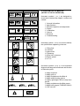
ILLUSTRATED SYMBOLS
GEN
INFO
(REFER TO THE ILLUSTRATION)
SPEC
E
Illustrated symbols Q to W are designed as
thumb tabs to indicate the chapter’s number and
content.
R
INSP
ADJ
ENG
T
Q General information
W Specifications
E Periodic inspection and adjustment
R Engine
T Carburetion
Y Chassis
U Electrical
I Troubleshooting
Y
CARB
CHAS
U
I
TRBL
SHTG
ELEC
O
P
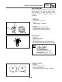
Illustrated symbols O to e are used to identify
the specifications appearing in the text.
}
{
T.
R
q
w
e
Illustrated symbols r to [ in the exploded
diagram indicate grade of lubricant and location
of lubrication point.
r
u
p
O Filling fluid
P Lubricant
{ Special tool
} Tightening
q Wear limit, clearance
w Engine speed
e Ω, V, A
y
t
i
o
[
r Apply engine oil
t Apply gear oil
y Apply molybdenum disulfide oil
u Apply wheel bearing grease
i Apply lightweight lithium-soap base
grease
o Apply molybdenum disulfide grease
p Apply locking agent (THREADLOCK ®)
[ Use new one
INDEX
GENERAL INFORMATION
GEN
INFO
1
SPECIFICATIONS
SPEC
2
PERIODIC INSPECTION
AND ADJUSTMENT
INSP
ADJ
3
ENGINE OVERHAUL
ENG
4
COOLING SYSTEM
ENG
5
CARBURETION
CARB
6
CHASSIS
CHAS
7
ELECTRICAL
ELEC
8
TRBL
SHTG
9
TROUBLESHOOTING
GEN
INFO
1
GEN
INFO
CHAPTER 1.
GENERAL INFORMATION
SCOOTER IDENTIFICATION ........................................................................ 1-1
VEHICLE IDENTIFICATION NUMBER .................................................... 1-1
ENGINE SERIAL NUMBER ..................................................................... 1-1
IMPORTANT INFORMATION ....................................................................... 1-2
ALL REPLACEMENT PARTS ................................................................. 1-2
GASKETS, OIL SEALS, AND O-RINGS .................................................. 1-2
LOCK WASHERS/PLATES AND COTTER PINS .................................... 1-2
BEARINGS AND OIL SEALS ................................................................... 1-2
CIRCLIPS ................................................................................................. 1-3
SPECIAL TOOLS ........................................................................................... 1-4
SCOOTER IDENTIFICATION
GEN
INFO
GENERAL INFORMATION
SCOOTER IDENTIFICATION
햲
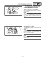
VEHICLE IDENTIFICATION NUMBER
The vehicle identification number Q is stamped
into the frame.
NOTE:
The vehicle identification number is used to
identify your scooter and may be used to register
your scooter with the licensing authority in your
state.
ENGINE SERIAL NUMBER
The engine serial number Q is stamped into the
crankcase.
햲
NOTE:
The first three digits of these numbers are for
model identifications; the remaining digits are
the unit production number.
NOTE:
Designs and specifications are subject to change
without notice.
1-1
IMPORTANT INFORMATION
GEN
INFO
IMPORTANT INFORMATION
ALL REPLACEMENT PARTS
1.Use only genuine parts for all replacements.
Use oil and/or grease recommended by MBK/
YAMAHA for assembly and adjustment. Other
brands may be similar in function and
appearance, but inferior in quality.
GASKETS, OIL SEALS, AND O-RINGS
1.All gaskets, seals and O-rings should be
replaced when an engine is overhauled. All
gaskets surfaces, oil seal lips and O-rings
must be cleaned.
2.Properly oil all mating parts and bearing during
reassembly. Apply grease to the oil seal lips.
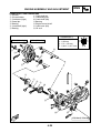
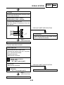
LOCK WASHERS/PLATES AND COTTER
PINS
1.All lock washers/plates Q and cotter pins
must be replaced when they are removed.
Lock tab(s) should be bent along the bolt or nut
flat(s) after the bolt or nut has been properly
tightened.
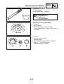
BEARINGS AND OIL SEALS
1.Install the bearing(s) Q and oil seal(s) W with
their manufacturer’s marks or numbers facing
outward. (In other words, the stamped letters
must be on the side exposed to view.) When
installing oil seal(s), apply a light coating of
lightweight lithium base grease to the seal
lip(s). Oil the bearings liberally when installing.
CAUTION :
Do not use compressed air to spin the
bearings dry. This causes damage to the
bearing surfaces.
1-2
IMPORTANT INFORMATION
GEN
INFO
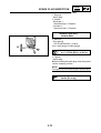
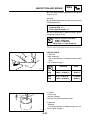
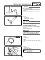
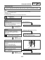
CIRCLIPS
1.All circlips should be inspected carefully before
reassembly. Always replace piston pin clips
once they have been removed. Replace bent
circlips. When installing a circlip Q make sure
that the sharp edge W is positioned opposite
to the thrust E it receives. See the sectional
view.
R Shaft
1-3
SPECIAL TOOLS
GEN
INFO
EB102000
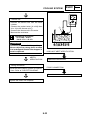
SPECIAL TOOLS
The following special tools are necessary for complete and accurate tune-up and assembly.
Use only the appropriate special tools; this will help prevent damage caused by the use of inappropriate
tools or improvised techniques.
When placing an order, refer to the list provided below to avoid any mistakes.
Tool N°
90890-01135
Tool name/usage
Crankcase separating tool
This tool is used to separate the crankcase and remove the crankshaft.
90890-01189
Flywheel puller
This tool is used to remove the flywheel
magneto.
90890-01235
Rotor holding tool
This tool is used to remove the flywheel
magneto.
90890-01274
90890-01275
90890-01277
90890-01411
Crankshaft installer set.
These tools are used to install the crankshaft.
90890-01348
Locknut wrench
This tool is used when removing or installing the secondary sheave nut.
90890-01701
Sheave holder
This tool is used to hold the secondary
sheave when removing or installing the
nut.
90890-01337
Clutch spring holder.
This tool is used for compressing the
spring of the secondary sheave when removing the nut.
1-4
Illustration
SPECIAL TOOLS
Tool N°
9079Q-02218
Tool name/usage
Ring nut wrench.
This tool is used to loosen and tighten the
steering ring nut.
90890-01326
90890-1294
T-handle
Damper rod holder
These tools are used for holding the
damper rod holder when removing or installing the damper rod holder.
90890-01184
90890-01186
Fork seal driver weight.
Fork seal driver attachment (ø27)
These tools are used wheninstalling the
fork seals.
90890-03112
Pocket Tester
This instrument is invaluable for checking the electrical system.
90890-03113
Engine tachometer.
This tool is needed for detecting the engine rpm.
90890-06754
Ignition checker.
This instrument is necessary for checking the ignition system components.
1-5
GEN
INFO
Illustration
SPEC
2
SPEC
CHAPTER 2.
SPECIFICATIONS
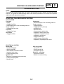
GENERAL SPECIFICATIONS ....................................................................... 2-1
MAINTENANCE SPECIFICATIONS .............................................................. 2-4
ENGINE ................................................................................................... 2-4
CHASSIS ................................................................................................. 2-6
ELECTRICAL ........................................................................................... 2-7
CABLE ROUTING .......................................................................................... 2-8
GENERAL SPECIFICATIONS
SPEC
SPECIFICATIONS
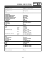
GENERAL SPECIFICATIONS
Model
YQ50
Dimensions:
Overall length
Overall width
Overall height
Seat height
Wheelbase
Minimum ground clearance
1.743 mm
690 mm
1.170mm
828 mm
1.256 mm
185 mm
Basic weight:
With oil and full fuel tank
97 kg
Minimum turning radius :
1.800 mm
Engine:
Type
Cylinder arrangement
Displacement
Bore x stroke
Compression ratio
Starting system
Lubrication system:
Oil type or grade:
Engine oil:
Transmission oil
Liquid-cooled 2-stroke, gasoline torque induction.
Single cylinder, horizontal
49 cm3
40 x 39.2 mm
7.9 : 1 (F)(B)(P)(E)(I)
8 : 1 (D)(NL)(CHE)
Electric and kick starter
Separate lubrication (Yamaha Autolube )
Semi-synthetic, in accordance with the
API TC TSC 3 Standard.
SAE 10W30 type SE motor oil
Oil capacity:
Transmission oil:
Periodic oil change
Total amount
0.11 L
0.13 L
Radiator capacity
Total amount (Including all routes)
1.2 L
Air filter:
Wet type element
Fuel:
Type
Tank capacity
Regular unleaded gasoline with a research octane
number of 91 or higher.
7.0 L
2-1
GENERAL SPECIFICATIONS
Model
YQ50
Carburetor:
Type/Manufacturer
PHBN12HS / DELL'ORTO
Spark plug:
Type/Manufacturer
Gap
BR8HS/NGK
0.5 ~ 0.7 mm
Clutch type:
Dry, centrifugal automatic
Transmission:
Primary reduction system
Primary reduction ratio
Secondary reduction system
Secondary reduction ratio
Transmission
Operation
Helical gear
52/13 (4.000)
Spur gear
43/14 (3.071)
V-belt
Automatic
Chassis:
Frame type
Caster angle
Trail
Steel tube underbone
27°
90 mm
Tire:
Type
Size
Manufacturer/type
Front
Rear
Front
Rear
Tire pressure (cold tire)
Front
Rear
Tubeless
130/60-13
140/60-13
PIRELLI / SL36
MICHELIN / BOPPER
PIRELLI / SL36
MICHELIN / BOPPER
150 kPa (1.50 kg/cm2)
150 kPa (1.50 kg/cm2)
Brake:
Front brake type
Operation
Rear brake type
Operation
Disc brake
Right hand operation
Disk brake
Left hand operation
Suspension:
Front
Rear
Telescopic fork
Unit swing
Shock absorber:
Front
Rear
Coil spring/Oil damper
Coil spring/Oil damper
Wheel travel:
Front wheel travel
Rear wheel travel
80 mm
72 mm
2-2
SPEC
GENERAL SPECIFICATIONS
Model
YQ50
Electrical:
Ignition system
Charging system
Battery type/model
Battery capacity
CDI
Flywheel magneto
GM4-3B, YB4L-B, FB4L-B
12V 4AH
Headlight type:
Bulb
Bulb wattage / quantity:
Headlight
Auxiliary light
Taillight/brake light
Flasher light
Front
Rear
Meter light
Warning lights wattage / quantity:
“OIL”
“HIGH BEAM”
“TURN”
“Cooling warning light“
12V 35W/35W x 1
12V 5W x 1
12V 5W/21W x 1
12V 21W x 2
12V 10W x 2
12V 1.2W x 3
12V 1.2W x 1
12V 1.2W x 1
12V 1.2W x 1
12V 1.2W x 1
2-3
SPEC
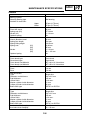
MAINTENANCE SPECIFICATIONS
SPEC
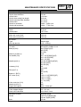
MAINTENANCE SPECIFICATIONS
ENGINE
Model
YQ50
Cylinder head:
Warp limit
0.02 mm
Lines indicate straight edge measurements.
*
Cylinder:
Bore size
<Limit>
Taper limit
39.993 ~ 40.012 mm
<40.1 mm>
0.05 mm
Piston:
Piston size
Measuring point
39.957 ~ 39.977 mm
5 mm
*
Piston clearance
<Limit>
Piston pin bore size
0.029 ~ 0.042 mm
<0.1 mm>
10.004 ~ 10.019 mm
Piston pin:
Outside diameter
9.996 ~ 10.000 mm
Piston ring:
Sectional sketch (BxT)/Type:
Top ring
2nd ring
End gap (installed):
Top ring
2nd ring
Side clearance (installed):
Top ring
2nd ring
1.5 ~ 1.8 mm
1.5 ~ 1.8 mm
B
0.15 ~ 0.35 mm
0.15 ~ 0.35 mm
T
0.03 ~ 0.05 mm
0.03 ~ 0.05 mm
Crankshaft:
C
C
E
D
Crank width “A”
A
Runout limit “C”
Connecting rod big end side clearance “D”
Big end radial clearance “E“
37.90 ~ 37.95 mm
0.03 mm
0.2 ~ 0.5 mm
0.004 ~ 0.017 mm
2-4
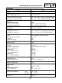
MAINTENANCE SPECIFICATIONS
Model
YQ50
Automatic centrifugal clutch:
Clutch shoe thickness
<Wear limit>
Clutch shoe spring free length
Clutch housing inside diameter
<Wear limit>
Clutch-in revolution
Clutch-stall revolution
2.0 mm
<1.0 mm>
29.9 mm
107.0 mm
107.4 mm
3.950 ~ 4.450 r.p.m.
6.900 ~ 7.700 r.p.m.
V-belt:
Width
<Wear limit>
16.5 mm
<15.7 mm>
Transmission:
Main axle runout limit
Drive axle runout limit
0.08 mm
0.08 mm
Kick starter:
Type
Kick clip tension
Ratchet type
0.15 ~ 0.25 kg
Carburetor:
I.D mark
Main jet (M.J)
Main air jet (M.A.J)
Jet needle (J.N)
Needle jet (N.J)
Cutaway (C.A)
Pilot jet (P.J)
Bypass 1 (B.P.1)
Air screw (A.S)
Valve seat size (V.S)
Starter jet (G.S.1)
Engine idle speed
Reed valve:
Valve stopper height
Reed valve clearance
Lubrication system:
Stroke
Bore
DELLORTO PHBN 12 HS
#86 (F)(B)(P)(I)(E)
#85 (CHE)
#74 (NL)
ø1.5
A21 - 2/5 (F)(B)(P)(I)(E)
A12 - 3/5 (D)(CHE)
A20 - 3/5 (NL)
210 GA (F)(B)(P)(I)(E)(D)
209 GA (CHE)
208 GA (NL)
3.0
4.0 (CHE)
#36
#34 (CHE)
0.8
1 3/8 ± 1/8 (F)(B)(P)(I)(E)
1 3/4 ± 1/8 (D)
1 5/8 ± 1/8 (NL)
2 ± 1/8 (CHE)
1.2
#45
1600 ~ 2000 rpm
6.0 ~ 6.4 mm
Less than 0.2 mm
Autolube pump
2.62 mm (F)(B)(P)(I)(E)
2.5 mm (D)(NL)(CHE)
0.5 mm
2-5
SPEC
MAINTENANCE SPECIFICATIONS
CHASSIS
Model
YQ50
Steering system:
Steering bearing type
No/Size of steel balls:
Ball bearing
Upper
Lower
Front suspension:
Front fork travel
Spring rate (K1)
Stroke (K1)
Optional spring
Rear suspension:
Shock absorber travel
Spring free length
Spring fitting length
Spring rate
Stroke
15 pcs (4.75 mm)
15 pcs (4.75 mm)
80 mm
5.7 N/mm
0 ~ 80 mm
No
(K1)
(K2)
(K1)
(K2)
Optional spring
60 mm
234 mm
199.5 mm
28 N/mm
35 mm
0 ~ 92 mm
92 ~ 115 mm
No
Wheels:
Front wheel type
Rear wheel type
Front wheel size/Material
Front wheel size/Material
Cast wheel
Cast wheel
MT 3.00 x13 / Aluminium
MT 3.50 x13 / Aluminium
Rim runout limit:
Front
Rear
1.0 mm
1.0 mm
Front disc brake:
Type
Diameter and thickness
Pad thickness
<Wear limit>
Master cylinder inside diameter
Caliper cylinder inside diameter
Brake fluid type
Single disc
190 x 3.5 mm
4.5 mm
<2.0 mm>
11 mm
30 mm
DOT# 3 or DOT#4
Rear disk brake:
Type
Diameter and thickness
Pad thickness
<Wear limit>
Master cylinder inside diameter
Caliper cylinder inside diameter
Brake fluid type
Single disc
190 x 3.5 mm
4.5 mm
<2.0 mm>
11 mm
30 mm
DOT# 3 or DOT#4
Front brake lever freeplay:
Rear brake lever freeplay:
10 ~ 20 mm
10 ~ 20 mm
2-6
SPEC
MAINTENANCE SPECIFICATIONS
SPEC
ELECTRICAL
Model
YQ50
Voltage:
12 V
Ignition system:
Ignition timing (B.T.D.C.)
14° at 5.000 r/min
CDI:
Pickup coil resistance (color)
Source coil resistance (color)
400 ~ 600 Ω at 20°C (68°F) (White/Red-Black)
640 ~ 960 Ω at 20°C (68°F) (Black/Red-Black)
Ignition coil:
Minimum spark length
Primary coil resistance
Secondary coil resistance
6 mm
0.56 ~ 0.84 Ω at 20°C (68°F)
5.68 ~ 8.52 Ωk at 20°C (68°F)
Spark plug cap:
Resistance
5 kΩ at 20°C (68°F)
CDI Magneto:
Lighting coil resistance
Lighting coil resistance
0.32 ~ 0.48 Ω at 20°C (68°F)(Yellow/Red-Black)
0.48 ~ 0.72 Ω at 20°C (68°F)(White-Black)
Voltage regulator/Rectifier:
Type
No load regulated voltage
Capacity
Withstand voltage
Semi-conductor, short-circuit type
13 ~ 14 V
8A
600 V
Battery:
Specific gravity
1.280
Starter motor:
Out put
Armature coil resistance
Brush overall lenght
<Wear limit>
Brush spring pressure
Commutator diameter
<Wear limit>
Mica undercut (depth)
0.14 kW
0.06 ~ 0.08 Ω at 20°C (68°F)
3.9 mm
0.9 mm
563 ~ 844 g
15.8 mm
14.8 mm
1.15 mm
Starter relay:
Amperage rating
Coil winding resistance
20 A
54 ~ 66 Ω at 20°C (68°F)
Horn:
Maximum amperage
2.5 A
Flasher relay:
Type
Self canceling device
Flasher frequency
Condenser type
No
80 ~ 160 cycle/min
Fuel gauge:
Sender unit resistance
Contact braker:
Main fuse
(full)
(empty)
1.5 ~ 7.5 Ω
90 ~ 100 Ω
7,5 A x 1
2-7
SPEC
CABLE ROUTING
A
B
C
D
E
F
G
H
I
J
K
L
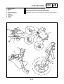
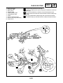
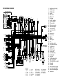
CABLE ROUTING
Q
W
E
R
T
Y
U
I
O
P
{
}
q
w
Handlebar end grip
Right handlebar switch
Left handlebar switch
Handlebar
Flasher harness
Right handlebar grip
Wireharness
Wireharness cord
Starter (choke) cable
Front handlebar cover
Speedometer case
Speedometer cable
Front brake hose
Rear brake hose
A
햲
C
햷
햳
Push the end grip againt the handlebar and tighten to 0.6 ~ 0.8 m.kg.
Tighten the front screw first.
Apply the left switch handle against the handlebar.
Hole for the front flasher harness.
Install the right handlebar grip in regard to the right handlebar switch.
Group the connexions here.
Attach the wiring harness cord on the handlebar bracket.
Pass the starter (choke) through the handle cover.
Glue the left handlebar grip.
Cut the band at 5 mm of his end.
Clip the front handlebar cover on the speedometer case.
Front steering assembly:
• Tighten the ring nut in order to eliminate all play.
• Take care of installing the special washer on the steering ball race:
teeth against teeth.
D
햴
B
햵
C
BB
I
E
A
햲
A
GG
C
DD
B
A
D
CC
B
D
HH
AA
H
햽
햶
H
햶
F
10°
G
햸
햹
1.0 ~ 3.0 mm
햺
K
H
햻
J
E
G
EE
L
햾 햸
G
J
B
헀
햿
J
E
햺 햳
2-8
SPEC
CABLE ROUTING
A
B
C
D
E
CABLE ROUTING
Q
W
E
R
T
Y
U
I
O
P
{
Fuel sender
Fuel tank
Fuel overflow pipe
Fuel cock
Pipe bracket
Frame
Trunk
Carburetor drain hose
Fuel pipe
Suction pipe
Bands
F
G
H
I
J
Insert the fuel sender completly.
Turn the fuel sender so that the cable points toward.
Pass the fuel lines above the rear brake hose.
Pass the fuel overflow pipe in the trunk slot.
Push the fuel cock (without turning it) completly in the tank and screw
the collar.
Install the hoses facing to the inside of the frame.
Pass the fuel tank pipe overflow and carburetor drain pipes in the
bracket.
Attach the fuel and suction pipes in the bands.
Pass the fuel overflow pipe inside the frame.
Install the fuel pipes without lubricating them.
햲
A
햲
B
햳
햳
햳
햸
C
D
햽
햷
햺
I
햸
햴
햻
햳
HJ
햵
E
X
5~
햶
m
0m
MA
1
G
F
햹
2-9
SPEC
CABLE ROUTING
Q
W
E
R
T
Y
U
I
O
P
{
}
q
w
e
r
A Set the seat lock adjuster so that there is a gap betwween 8 ~ 9 mm
at the seat lock aperture.
B Install the starter relay on the footrest board.
C Group the connections here.
D Turn the connectors towards.
E Puch the wiring inside.
F Pass the wiring harness through the footrest board.
G Turn the ground lead one turn around the starter motor leads.
H The water temperature sender lead must go straight to the wiring
harness.
I Put one drop of Loctite 542 on the tread before installing the water
temperature sender.
J Install the head light protector correctly.
K Pass the main switch lead between the rectifier/regulator and the
steering head pipe.
Seat lock
Starter motor
Ignition coil
Battery
Starter relay
Fuse housing
Rear brake hose
Fuel sender
CDI unit
Oil lever gauge
Main switch
Rectifier/regulator
Head light
Water hose
Water temperature sender
Seat lock cable adjuster
햲
햳
A
햵
햹
햷
햴
D
햶B
햸
E
F
햺
햽
햿
햾
헂
햻
C
K
G
헀
LT
H
I
2-10
헁
J
CABLE ROUTING
Q
W
E
R
T
Y
U
I
P
Wiring harness
Resistor
Horn
Front brake hose
Speedometer cable
Radiator
Water tank
Clamps
Frame
A
B
C
D
Install the wiring harness in the middle of the frame.
Set the resistor at 45°0/+30’ on the frame bracket.
Clip the front brake hose on the front fork bracket.
Install the 8 clamps just beside the marks at the end side of the hoses.
햸
햸
햷
햷
햸
E
SPEC
햷
햹
햲
햺
햷
햴
햳
햶
햵
2-11
CABLE ROUTING
Q
W
E
R
T
Y
U
I
O
P
Rear brake hose
Seat lock cable
Wire harness
Throttle cable
Starter (choke) cable
Speedometer cable
Frame
Oil hose (tank/oil pump)
Oil hose (oil pump/carburetor)
Water hoses
SPEC
A Install the rear brake hose in the clip.
B Install the oil delivery hose (from oil pump to carburator) under the
water hose.
C Pass the rear brake hose under the frame reinforcement tube.
D Align the mark on the water hose in front of the mark in the water pump
housing.
E Pass the speedometer cable through the slot of the front fender.
F Install the 8 clamps just beside the marks at the end side of the hoses.
A
햸
햲
27°±10°
햳
햲
햴
햲
햸
햲
F
햵
햶
햸
햺B
C
D
햻
햹
햸
E
햷
햻
2-12
CHK
ADJ
3
CHK
ADJ
CHAPTER 3.
PERIODIC INSPECTION AND ADJUSTMENT
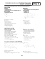
INTRODUCTION ............................................................................................ 3-1
PERIODIC MAINTENANCE/LUBRICATION INTERVALS ............................ 3-1
COVERS ........................................................................................................ 3-3
REMOVAL ................................................................................................ 3-3
HANDLEBAR COVERS ................................................................................. 3-7
REMOVAL ................................................................................................ 3-7
ENGINE ....................................................................................................... 3-11
ENGINE IDLE SPEED ADJUSTMENT .................................................. 3-11
THROTTLE CABLE FREE PLAY ADJUSTMENT ................................. 3-12
SPARK PLUG INSPECTION ................................................................. 3-13
AUTOLUBE PUMP AIR BLEEDING ...................................................... 3-14
ENGINE OIL LEVEL INSPECTION ....................................................... 3-15
TRANSMISSION OIL REPLACEMENT ................................................. 3-16
COOLANT LEVEL INSPECTION ........................................................... 3-17
COOLANT REPLACEMENT .................................................................. 3-17
AIR CLEANER ELEMENT CLEANING .................................................. 3-19
EXHAUST PIPE ASSEMBLY AND ADJUSTMENT ............................... 3-20
CHASSIS ..................................................................................................... 3-21
FRONT BRAKE LEVER FREE PLAY ADJUSTMENT ........................... 3-21
REAR BRAKE LEVER FREE PLAY ADJUSTMENT ............................. 3-21
BRAKE PAD INSPECTION .................................................................... 3-21
BRAKE FLUID LEVEL INSPECTION .................................................... 3-22
AIR BLEEDING (HYDRAULIC BRAKE SYSTEM) ................................. 3-23
STEERING HEAD ADJUSTMENT ......................................................... 3-23
TIRE INSPECTION ................................................................................ 3-24
WHEEL INSPECTION ........................................................................... 3-25
CABLE INSPECTION AND LUBRICATION ........................................... 3-25
LEVER LUBRICATION .......................................................................... 3-26
CENTERSTAND LUBRICATION ........................................................... 3-26
FRONT FORK INSPECTION ................................................................. 3-26
REAR SHOCK ABSORBER .................................................................. 3-26
ELECTRICAL ............................................................................................... 3-27
BATTERY INSPECTION ........................................................................ 3-27
FUSE INSPECTION ............................................................................... 3-28
HEADLIGHT BEAM ADJUSTMENT ...................................................... 3-29
HEADLIGHT LENS REPLACEMENT .................................................... 3-29
HEADLIGHT BULB REPLACEMENT .................................................... 3-29
INTRODUCTION/PERIODIC MAINTENANCE/
LUBRICATION INTERVALS
INSP
ADJ
PERIODIC INSPECTION AND ADJUSTMENT
INTRODUCTION
This chapter includes all information necessary to perform recommended inspections and adjustments.
These preventive maintenance procedures, if followed, will ensure more reliable vehicle operation and
a longer service life. The need for costly overhaul work will be greatly reduced. This information applies
to vehicles already in service as well as new vehicles that are being prepared for sale. All service
technicians should be familiar with this entire chapter.
PERIODIC MAINTENANCE/LUBRICATION INTERVALS
Unit : Km(miles)
EVERY
ROUTINE
ITEM
1
Spark plug
2
Air filter
3
*
Carburetor
4
*
Fuel line
5
*
Transmission oil
6
*
Autolube pump
7
*
Brakes (front and rear)
8
*
Cooling system
9
*
Wheels
10 *
Wheel bearings
11 *
Steering bearing
12 *
Rear shock absorber
13 *
V-belt
14 *
Fitting/Fasteners
15 *
Centerstand
16 *
Battery
•
•
•
•
•
•
•
•
•
•
•
•
•
•
•
•
•
•
•
•
•
•
•
•
•
•
•
•
•
•
•
•
•
•
•
•
•
Check condition.
Clean or replace if necessary.
Clean.
Replace if necessary.
Check idle speed/choke operation.
Adjust if necessary.
Check fuel hose and vacuum pipe for cracks or
damage.
Replace if necessary.
Check for oil leakage.
Correct if necessary.
Replace every 12,000 (8,000) or 24 months.
(Warm engine before draining.)
Check operation.
Correct if necessary.
Bleed the air.
Check operation/fluid leakage/See NOTE.
Correct if necessary.
Check hoose condition.
Replace if necessary.
Replace coolant every 12.000 (8,000) or 24 months.
Check damage/runout/Tightening torque.
Replace/tighten if necessary.
Check bearing assembly for looseness/damage.
Replace if damaged.
Check bearing assembly for looseness.
Correct if necessary.
Moderately repack every 12,000 (8,000) or 24 months.**
Check operation/oil leakage.
Replace if necessary.
Check damage and wear.
Replace if necessary.
Check all chassis fittings and fasteners.
Tighten if necessary.
Check operation.
Repair if necessary.
Check specific gravity.
Check breather pipe for proper operation.
Correct if necessary.
Items marked with an asterisk (*) require special tools, data and technical skills for servicing.
Take the scooter to a Yamaha or MBK Dealer when servicing these items.
** : Medium weight wheel bearing grease.
3-1
BREAK-IN
1,000(600)
REPLACE
3,000
(2,000)or
6 months
6,000
(4,000)or
12 months
PERIODIC MAINTENANCE/LUBRICATION INTERVALS
INSP
ADJ
NOTE:
Brake fluid replacement:
1.When disassembling the master cylinder or caliper cylinder, replace the brake fluid. Normally check
the brake fluid level and add fluid as required.
2.On the inner parts of the master cylinder and caliper cylinder, replace the oil seals every two years.
3.Replace the brake hoses every four years, or when cracked or damaged.
3-2
INSP
ADJ
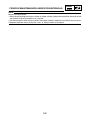
COVERS
REMOVAL
T.R
8 Nm (0,8 m.kg)
T.R
2
3 Nm (0,3 m.kg)
1
5
3
4
4
T.R
8 Nm (0,8 m.kg)
T.R
Mark
1
2
3
4
5
Name of the intervention/
of the part
Qty
Seat
Fuel tank cap
Rear seat screws and strap
Side cover (left and right)
Rear seat
2 Nm (0,2 m.kg)
Observation
1
1
2
2
1
CAUTION:
When removing the cover, be careful
not to damage the mounting clips.
For installation,reverse the
“REMOVAL” procedure
3-3
INSP
ADJ
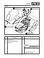
COVERS
REMOVAL
T.R
T.R
3 Nm (0,3 m.kg)
8 Nm (0,8 m.kg)
4
3
5
T.R
2,5 Nm (0,25 m.kg)
2
3
1
T.R
Mark
1
2
3
4
5
Name of the intervention/
of the part
Qty
Glove compartment cover
Oil cover
Side cover (left and right)
Box
Rear mudguard
6 Nm (0,6 m.kg)
Observation
1
1
2
1
1
CAUTION:
When removing the cover, be careful
not to damage the mounting clips.
For installation,reverse the
“REMOVAL” procedure
3-4
INSP
ADJ
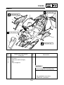
COVERS
REMOVAL
6,5 Nm (0,65 m.kg)
T.R
13 Nm (1,3 m.kg)
T.R
1
4
2
T.R
T.R
3 Nm (0,3 m.kg)
6,5 Nm (0,65 m.kg)
3
2 Nm (0,2 m.kg)
T.R
Mark
1
2
3
4
Name of the intervention/
of the part
Qty
Frame reinforcement
Fuel tank
Rear lower cover
Rear light
Observation
1
1
1
1
CAUTION:
When removing the cover, be careful
not to damage the mounting clips.
For installation,reverse the
“REMOVAL” procedure
3-5
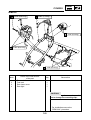
COVERS
INSP
ADJ
REMOVAL
T.R
3 Nm (0,3 m.kg)
T.R
3 Nm (0,3 m.kg)
1
2
T.R
2
2 Nm (0,2 m.kg)
4
T.R
3 Nm (0,3 m.kg)
3
T.R
Mark
1
2
3
4
3 Nm (0,3 m.kg)
Name of the intervention/
of the part
Qty
Front cover and headlight
Front inner cover
Front fender
Front inner panel
Observation
1
1
1
1
CAUTION:
When removing the cover, be careful
not to damage the mounting clips.
For installation,reverse the
“REMOVAL” procedure
3-6
INSP
ADJ
COVERS
HANDLEBAR COVERS
T.R
3 Nm (0,3 m.kg)
T.R
3 Nm (0,3m.kg)
3
2
1
4
Mark
1
2
3
4
T.R
3 Nm (0,3 m.kg)
Name of the intervention/
of the part
Qty
Handlebar cover (front)
Handlebar cover (rear)
Meter
Flasher light
Observation
1
1
1
1
CAUTION:
When removing the cover, be careful
not to damage the mounting clips.
For installation,reverse the
“REMOVAL” procedure
3-7
INSP
ADJ
COVERS
REMOVAL
T.R
3 Nm (0,3 m.kg)
1
T.R
3 Nm (0,3 m.kg)
2
Mark
1
2
Name of the intervention/
of the part
Qty
Battery cover
Lower cover
Observation
1
1
CAUTION:
When removing the cover, be careful
not to damage the mounting clips.
For installation,reverse the
“REMOVAL” procedure
3-8
INSP
ADJ
COVERS
REMOVAL
T.R
4 Nm (0,4 m.kg)
1
T.R
4 Nm (0,4 m.kg)
2
Mark
Name of the intervention/
of the part
Qty
1
Inner panel
1
2
Footrest board
1
Observation
Main switch ring. Turn the ring
anticlockwise to remove it
CAUTION:
When removing the cover, be careful
not to damage the mounting clips.
For installation,reverse the
“REMOVAL” procedure
3-9
COVERS
INSP
ADJ
NOTE:
Correct routing of cables and wires is essential for a safe operation of this scooter. Refer to the section
“CABLE ROUTING” in Chapter 2.
NOTE:
Be careful not to pinch any wires with the covers.
NOTE:
When installing the covers, be careful not to damage the mounting clips.
3-10
ENGINE IDLE SPEED ADJUSTMENT
INSP
ADJ
ENGINE
ENGINE IDLE SPEED ADJUSTMENT
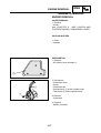
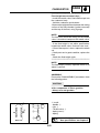
1. Tighten :
• Pilot air screw
Turn the pilot air screw in until lightly seated.
2. Loosen :
• Pilot air screw
Back out from the lightly seated position.
Pilot air screw position :
DELL'ORTO
1-3/8 turns out ± 1/8 (F)(B)(P)(I)(E)
1-3/4 turns out ± 1/8 (D)
1-5/8 turns out ± 1/8 (NL)
2 ± 1/8 turns out (CHE)
3. Start the engine and let it warm up for several
minutes.
WARNING
For safety reasons, place the scooter on the
center stand before starting the engine.
4. Attach :
• Inductive tachometer
(to the spark plug lead)
Inductive tachometer:
Ref: 90890-03113
5. Check :
• Engine idle speed
Out of specification ➔ Adjust.
Engine idle speed :
1800 ± 200 r/min
3-11
ENGINE IDLE SPEED ADJUSTMENT/
THROTTLE CABLE FREE PLAY ADJUSTEMENT
INSP
ADJ
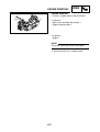
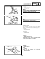
6. Adjust :
• Engine idle speed
********************************************************
Adjustment steps :
• Turn the throttle stop screw in or out until
specified idling speed is obtained.
Turning left
Idling speed increased.
Turning right
Idling speed decreased.
*******************************************************
THROTTLE
CABLE
FREE
PLAY
ADJUSTMENT
1 Check :
• Throttle cable free play
Out of specification ➞ Adjust.
Free play :
1,0 ~ 3,0 mm (0.04 ~ 0.19 in)
*******************************************************
Throttle cable free play adjustment steps :
NOTE:
Before adjusting the throttle cable free play, the
engine idle speed should be adjusted.
First step :
• Loosen the locknut on the throttle cable.
• Turn the adjuster in or out until the specified
free play is obtained.
Turning left
Free play increased.
Turning right
Free play decreased.
• Tighten the locknuts.
WARNING
After adjusting, turn the handlebar to the
right and left, making sure that the engine
idling speed does not change.
*******************************************************
3-12
SPARK PLUG INSPECTION
INSP
ADJ
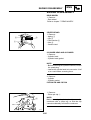
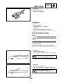
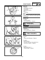
SPARK PLUG INSPECTION
1. Remove :
• Spark plug
2. Inspect :
• Electrode Q
Wear/Damage ➞ Replace.
• Insulator W
Abnormal color ➞ Replace.
Standard spark plug :
BR8HS (NGK)
3. Measure :
• Plug gap @
Out of specification ➞ Adjust.
Use a wire gauge or feeler gauge.
@
Spark plug gap @ :
0,5 ~ 0,7 mm (0.019 ~ 0.027 in)
4. Tighten :
• Spark plug
Before installing the spark plug, clean the gasket
surface and plug surface.
NOTE:
First tighten by hand, then torque to specification.
Spark plug :
20 Nm (2.0 m.kg)
3-13
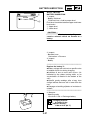
AUTOLUBE PUMP AIR BLEEDING
INSP
ADJ
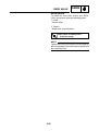
AUTOLUBE PUMP AIR BLEEDING
1. Bleed :
• Pump housing and oil hose
*******************************************************
Pump bleeding steps :
● Place a rag under the pump.
● Remove the bleed screw .
● Let oil run until there are no more air bubbles
in it.
● When there are no more bubbles, tighten the
bleed screw.
NOTE:
Check the condition of the bleed screw gasket.
If it is damaged, replace it with a new one.
● Start
the engine.
● Let the engine run two or three minutes at 2000
rpm. This will force out any air in the hose.
*******************************************************
3-14
ENGINE OIL LEVEL INSPECTION
INSP
ADJ
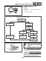
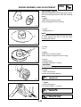
ENGINE OIL LEVEL INSPECTION
1. Inspect :
• Oil level
Oil level low ➞ Add oil to proper level as
follows.
Q “OIL” indicator light
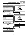
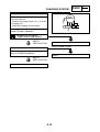
OIL LEVEL AND GAUGE CHECK
Turn main switch
to " "
*
"OIL" indicator
doesn't light.
"OIL" indicator
light.
Turn main switch
to "ON".
"OIL" indicator goes
Inspect Faulty
electrical circuit,
Light bulb etc.
Engine oil level
and electric circuit
are OK.
"OIL" indicator
stays on.
Add oil.
"OIL" indicator
stays on.
Recommended oil :
Semi-synthetic oil in accordance
with APITC TSC3 STANDARD.
Capacity :
Total:
1.3 L (1.14 Imp qt, 1.37 US qt)
NOTE:
Install the oil tank filler cap Q and push it fully
into the filler.
CAUTION:
Always use the same type of engine oil;
mixing oils may result in a harmful chemical
reaction and lead to poor performance.
3-15
TRANSMISSION OIL REPLACEMENT
INSP
ADJ
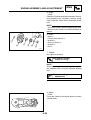
TRANSMISSION OIL REPLACEMENT
1. Remove :
• Drain plug Q
• Oil filler plug W
Drain the transmission oil.
2. Check :
• Gasket (drain plug)
• O-ring (oil filler plug)
Damaged ➞ Replace.
3. Install :
• Gasket • Drain plug
T.
R
Drain plug :
18 Nm (1.8 m.kg)
4. Fill :
• Transmission case
Transmission oil :
SAE 10W30 type SE motor oil.
Capacity :
Periodic replacement
0.11 L (0.10 Imp qt ; 0.12 US qt)
Total amount
0.13 L (0.11 Imp qt ; 0.13 US qt)
NOTE:
Wipe off any oil spilt on the crankcase, tire or
wheel.
5 Install :
• Oil filler plug
3-16
COOLANT LEVEL INSPECTION/
COOLANT REPLACEMENT
INSP
ADJ
COOLANT LEVEL INSPECTION
NOTE:
Install the scooter straight up when inspecting
the coolant level.
1.Place the scooter on a level surface.
NOTE:
Place the scooter on its centerstand.
2.Remove:
• Front cover
Refer to the section "COVER"
3.Inspect:
• Coolant level
Coolant level should be between maximum and minimum marks.
Coolant level low → Add recommanded coolant
to proper level.
CAUTION:
Hard water or salt water is harmful to the
engine parts; use boiled or distilled water if
you can't get soft water.
4.Install:
• Front cover
Refer to the section "COVER"
COOLANT REPLACEMENT
1.Remove:
• Front cover
Refer to the section "COVER"
• Radiator cap WARNING
Do not remove the radiator cap when the
engine and radiator are hot. Scalping hot
fluid and steam may be blown out under
pressure, which could cause serious injury.
When the engine has cooled, open the
radiator cap by followingthis procedure:
Place a thick rag or a towel over the radiator
cap. Slowly rotate the cap counterclockwise
3-17
COOLANT REPLACEMENT
INSP
ADJ
toward the detent. This allows any residual
pressure to escape. When the hissing soound
has stopped, press down on the cap while
turning counterclockwise and remove it.
NOTE:
Position the scooter straight up when replacing
the coolant.
2.Place the scooter on a level surface.
NOTE:
Place the scooter on its centerstand if.
3.Remove:
• Water pump fixing bold
Drain the radiator and engine of its coolant.
4.Install:
• Gasket
• Water pump fixing bold.
T.
R
Water pump fixing bold:
7 Nm (0.7 m.kg)
5.Fill:
• Cooling system (radiator, engine and hoses)
(to specified level)
Recommended coolant:
High quality ethylene glycol
antifreeze containing corrosion
inhibitors for aluminum engines.
Radiator capacity
(including all routes):
1.2 L (1.05 Imp qt, 1.27 US qt)
From lower to upper level:
0.15 L (0.13 Imp qt, 0.16 US qt)
3-18
AIR CLEANER ELEMENT CLEANING
INSP
ADJ
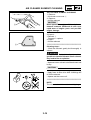
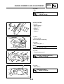
AIR CLEANER ELEMENT CLEANING
1. Remove :
• Air cleaner case cover Q
2. Remove :
• Air filter element
CAUTION:
Never operate the engine with the air cleaner
element removed. Unfiltered air will cause
rapid wear of engine parts and possible
engine damage.
3.Inspect :
• Element Q
Damage ➞ replace.
4.Clean :
• Air filter element
*******************************************************
Cleaning steps :
• Wash the element gently but thoroughly in
solvent.
WARNING
Never use low flashpoint solvents such as
gasoline to clean the element. Such solvents
may lead to fire or explosion.
• Squeeze excess solvent out of the element and
let dry.
CAUTION:
Do not twist the element.
• Apply foam air filter oil or SAE 10W30 typ SE
oil on the element.
• Sqeeze out the excess oil.
*******************************************************
NOTE:
The element should be wet but not dripping.
3-19
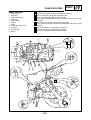
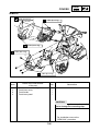
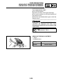
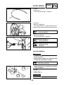
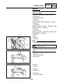
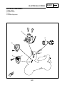
EXHAUST PIPE ASSEMBLY AND ADJUSTMENT
INSP
ADJ
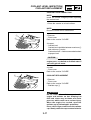
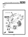
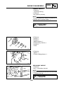
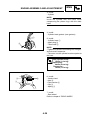
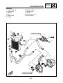
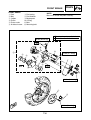
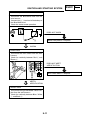
MUFFLER
Q Exhaust pipe
W Cylinder
E Crankcase
R Bolt
T Bolt
Y Gasket
4.5 Nm (0.45 m.kg)
29 Nm (2.9 m.kg)
7 Nm (0.7 m.kg)
3-20
FRONT BRAKE LEVER FREE PLAY ADJUSTEMENT/
REAR BRAKE LEVER FREE PLAY ADJUSTEMENT/
BRAKE PAD INSPECTION
INSP
ADJ
CHASSIS
@
FRONT BRAKE LEVER FREE PLAY
ADJUSTMENT
1. Check :
• Front brake lever free play @
Out of specification ➞ Adjust.
Free play :
10 ~ 20 mm (0.40 ~ 0.80 in)
WARNING
A soft or spongy feeling in the brake lever can
indicate the presence of air in the brake
system. This air must be removed by bleeding
the brake system before the scooter is
operated. Air in the system will reduce brake
performance and can result in loss of control
and an accident. Inspect and bleed the system
if necessary.
REAR BRAKE LEVER FREE PLAY
ADJUSTMENT
1. Check :
• Rear brake lever free play @
Out of specification ➞ Adjust.
@
Free play :
10 ~ 20 mm (0.40 ~ 0.80 in)
BRAKE PADS INSPECTION
1.Measure :
• Brake pads
Out of specification ➞ Replace.
NOTE:
Replace the brake pad and spring as a set when
replacing the brake pads.
Wear limit :
2,0 mm (0.08 in)
3-21
BRAKE FLUID LEVEL INSPECTION
INSP
ADJ
BRAKE FLUID LEVEL INSPECTION
NOTE:
Position the scooter straight up when inspecting
the fluid level, and make sure be turning the
handlebar that the top of the master cylinder is
horizontal.
1. Inspect :
• Brake fluid level
Brake fluid level is under “LOWER” level line
Q ➞ Fill to proper level.
Recommended brake fluid :
DOT # 3 or DOT # 4
CAUTION:
The brake fluid may corrode painted surfaces
or plastic parts. Always clean up spilled fluid
immediately.
WARNING
• Use only the designated quality fluid.
Otherwise, the rubber seals may deteriorate
causing leakage and poor brake
performance.
• Refill with the same type of fluid. Mixing
fluids may result in a harmful chemical
reaction leading to poor brake performance.
• Be careful that water does no enter the
master cylinder when refilling. Water will
significantly lower the boiling point of the
fluid and may result in vapor lock.
3-22
AIR BLEEDING (HYDRAULIC BRAKE SYSTEM)/
STEERING HEAD ADJUSTEMENT
INSP
ADJ
AIR BLEEDING
(HYDRAULIC BRAKE SYSTEM)
346002
1. Bleed :
• Brake fluid.
*******************************************************
Air bleeding steps :
a. Add proper brake fluid into the reservoir.
b. Install the diaphragm. Be careful not to spill
any fluid or allow the reservoir to overflow.
c. Connect a clear plastic tube Q tightly to the
caliper bleed screw.
d. Place the other end of the tube into a container.
e. Slowly apply the brake lever several times.
f. Pull the lever as far as possible and hold it
there.
g. Loosen the bleed screw and pull the lever all
the way.
h. When the lever is completely pulled, tighten
the bleed screw, then release the lever.
i. Repeat steps (e) to (h) until all air bubbles have
been removed from the system.
j. Add brake fluid to proper level.
*****************************************************
WARNING
Check the operation of the brake after
bleeding the brake system.
STEERING HEAD ADJUSTMENT
1 Check :
• Steering assembly bearings
Grasp the bottom of the forks and gently rock the
fork assembly back and forth.
Looseness ➞ Adjust steering head.
*******************************************************
Steering head adjustment steps :
● Remove the front fender and the front panels.
Refer to “COVERS REMOVAL” .
● Unscrew the securing nut Q
● Tighten the nut W
Stearing head wrench :
9079Q - 02218
354002
3-23
AIR BLEEDING (HYDRAULIC BRAKE SYSTEM/
STEERING HEAD ADJUSTEMENT
INSP
ADJ
Securing nut :
23 Nm (2.3 m.kg)
NOTE :
Install the torque wrench on the ring nut wrench
so that it makes a 90° angle with it.
●
354001
Move the handlebar up and down and from
front to rear. If steering play is too important,
tighten the nut to the specified torque.
Stearing head nut :
60 Nm (6.0 m.kg)
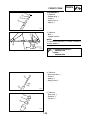
TIRE INSPECTION
1. Measure :
• Air pressure
Out of specification ➞ Adjust.
Tire pressure (cold)
Up to 90 kg
90 kg ~ maximum
load *
Maximum load :
WARNING
Front
Rear
150 kPa
150 kPa
(1.50 kgf/cm2) (1.50 kgf/cm2)
150 kPa
150 kPa
2
(1.50 kgf/cm ) (1.50 kgf/cm2)
180 kg (396.9 lb)
* Maximum load is the total weight of rider, passenger,
accessories and luggage.
3-24
Proper loading of your scooter is important
for the handling, braking, and other performance and safety characteristics of your
scooter. Do not carry loosely packed items
that can shift.
Securely pack your heaviest items close to
the center of the scooter, and distribute the
weight evenly from side to side. And check
the condition and pressure of your tires.
NEVER OVERLOAD YOUR SCOOTER.
Make sure the total weight of the cargo, rider,
passenger, and accessories (fairing,
saddlebags, etc. if approved for this model)
does not exceed the maximum load of the
scooter. Operation of an overloaded scooter
could cause tire damage, an accident, or
even injury.
TIRE INSPECTION/WHEEL INSPECTION/
CABLE INSPECTION AND LUBRICATION
INSP
ADJ
2 Inspect :
• Tire surface
Wear/Damage/Cracks/Road hazards ➞
Replace.
• Aluminum wheels
Damage/Bends ➞ Replace.
Never attempt even small repairs to the wheel.
WARNING
Ride conservatively after installing a tire to
allow it to seat itself properly on the rim.
• If the tire is removed with a tire lever, use a
suitable protection to prevent damaging the rim.
• When installing the tire, make sure the arrow
points to the front.
3.Measure :
• Tire tread depth
Out of specification ➞ Replace.
Minimum tire tread depth
(front and rear) :
0,8 mm (0.03 in)
Q Tread depth
W Side wall
E Wear indicator
WHEEL INSPECTION
1.Inspect :
• Wheels
Damage/Bends ➞ Replace.
WARNING
Never attempt even small repairs to the wheel.
CABLE INSPECTION AND LUBRICATION
WARNING
A damaged cable sheath will rapidly corrode.
As a result, the cable cannot move smoothly
inside the sheath. Since this situation is
dangerous, replace a damaged cable
immediately.
1. Check :
• Cable sheath
• Cable end
Damage ➞ Replace.
3-25
CABLE INSPECTION AND LUBRICATION/
FRONT FORK INSPECTION/
REAR SHOCK ABSORBER
INSP
ADJ
2. Check :
• Cable movement
Stickiness ➞ Lubricate.
Recommended lubricant :
Engine oil SAE 10W30
NOTE:
Hold the cable end up and pour a few drops of oil
into the sheath.
3. Lubricate the throttle cable end and the cable
guide notch on the throttle grip with grease Q.
Recommanded lubricant :
Lithium soap based grease
LEVER LUBRICATION
1. Lubricate rotating parts of the levers
Recommended lubricant :
Engine oil SAE 10W30
CENTERSTAND LUBRICATION
1. Lubricate rotating parts
Recommended lubricant :
Engine oil SAE 10W30
FRONT FORK INSPECTION
1.Check :
• Front fork
Bend/Damage ➞ Replace fork assembly as a
set.
Excessive oil leakage ➞ Replace fork assembly
as a set.
Unsmooth operation ➞ Replace fork assembly.
REAR SHOCK ABSORBER
1.Check :
• Rear shock absorber Oil leaks/Damage ➞ Replace.
2.Check :
• Tightening torque
T.
R
3-26
Upper bolt :
31 Nm (3.1 m.kg)
Lower bolt :
18 Nm (1.8 m.kg)
BATTERY INSPECTION
INSP
ADJ
ELECTRICAL
UPPER
LOWER
+
BATTERY INSPECTION
1. Inspect :
• Battery fluid level
Fluid level low ➞ Add to proper level.
Fluid level should be between upper and lower
level marks.
Q Upper level
W Lower level
CAUTION:
Refill with distilled water only. Tap water
contains minerals which are harmful to a
battery.
2. Inspect :
• Breather hose
Obstruction ➞ Remove.
3. Inspect :
• Battery
*******************************************************
Replace the battery if :
● Battery voltage will not rise to a specific value
or bubbles fail to rise during charging.
● Sulfation of one or more cells occurs. (As
indicated by the plates turning white, or an
accumulation of material in the bottom of the
sell.)
● Specific gravity readings after a long, slow
charge indicate that one cell is lower than the
rest.
● Warpage or buckling of plates or insulators is
evident.
*********************************************************
4. Measure :
• Specific gravity
Less than 1.280 ➞ Recharge battery.
Charging Current :
0.4 amps/10 hrs
Specific Gravity :
1.280 at 20°C (68° F)
3-27
BATTERY INSPECTION/
FUSE INSPECTION
INSP
ADJ
CAUTION:
Always charge a new battery before using
it to ensure maximum performance.
WARNING
Battery electrolyte is dangerous. It contains
sulfuric acid which is poisonous and highly
caustic.
Always follow these preventive measures :
• Avoid bodily contact with electrolyte as it
can cause severe burns and permanent
eye injury.
• Wear protective eye gear when handling or
working near batteries.
Antidote (EXTERNAL) :
• SKIN – Flush with water.
• EYES – Flush with water for 15 minutes and
get immediate medical attention.
Antidote (INTERNAL) :
• Drink large quantities of water or milk.
Follow with milk of magnesia, beaten egg,
or vegetable oil. Get immediate medical
attention.
Batteries generate explosive hydrogen gas.
Always follow these preventive measures:
• Charge batteries in a well-ventilated area.
• Keep batteries away from fire, sparks, or
open flames (e.g., welding equipment,
lighted cigarettes, etc.)
• DO NOT SMOKE when charging or handling
batteries.
KEEP BATTERIES AND ELECTROLYTE OUT
OF REACH OF CHILDREN.
FUSE INSPECTION
1. Remove the battery cover.
2. Inspect :
• Fuse Blown ➞ Replace.
3-28
FUSE INSPECTION/
HEADLIGHT BEAM ADJUSTEMENT
HEADLIGHT LENS REPLACEMENT
INSP
ADJ
******************************************************
Fuse replacement steps :
● Turn off the ignition.
● Install a new fuse of the right amperage.
● Turn on the switches to verify the operation of
the electric circuit.
● If the fuse immediately blows again, check the
electric circuit.
*******************************************************
WARNING
Never use a fuse with a rating higher than
specified. An improper fuse may cause
damage to the electrical circuit, and possibly
cause a fire.
Fuse :
Main circuit : 7,5 A
HEADLIGHT BEAM ADJUSTMENT
1. Adjust :
• Headlight beam
3-29
Higher
Turn out screw Q
Lower
Turn in screw W
HEADLIGHT LENS REPLACEMENT
HEADLIGHT BULB REPLACEMENT
INSP
ADJ
HEADLIGHT LENS REPLACEMENT
1. Remove :
• Front cover Q
2. Remove :
• Headlight lens
(Pull out the pins)
3. Remove :
• Gasket
4. Install :
Reverse the “REMOVAL” procedure.
HEADLIGHT BULB REPLACEMENT
1. Remove :
• Front cover
2. Remove :
• Headlight bulb socket Q
(Turn one quart of a turn).
3. Remove :
• Headlight bulb
4. Install :
Reverse the “REMOVAL” procedure.
3-30
ENG
4
ENG
CHAPTER 4.
ENGINE OVERHAUL
ENGINE REMOVAL ....................................................................................... 4-1
COVER REMOVAL .................................................................................. 4-1
COOLING SYSTEM ................................................................................. 4-1
CARBURETOR ........................................................................................ 4-1
CABLES, LEADS AND HOSES ............................................................... 4-2
ENGINE REMOVAL ................................................................................. 4-3
ENGINE DISASSEMBLY ............................................................................... 4-4
REAR WHEEL ......................................................................................... 4-4
CENTER STAND ..................................................................................... 4-4
CYLINDER HEAD AND CYLINDER ........................................................ 4-4
PISTON PIN AND PISTON ...................................................................... 4-4
KICK STARTER ....................................................................................... 4-5
PRIMARY SHEAVE ................................................................................. 4-6
SECONDARY SHEAVE ........................................................................... 4-6
STARTER SYSTEM ................................................................................. 4-7
TRANSMISSION ...................................................................................... 4-8
CDI MAGNETO ........................................................................................ 4-8
AUTOLUBE OIL PUMP ............................................................................ 4-9
CRANKCASE AND CRANKSHAFT ......................................................... 4-9
INSPECTION AND REPAIR ........................................................................ 4-11
CYLINDER HEAD .................................................................................. 4-11
CYLINDER AND PISTON ...................................................................... 4-11
PISTON RINGS ..................................................................................... 4-13
PISTON PIN AND PISTON PIN BEARING ............................................ 4-14
KICK STARTER ..................................................................................... 4-15
TRANSMISSION .................................................................................... 4-15
AUTOLUBE PUMP ................................................................................ 4-16
CRANKSHAFT ....................................................................................... 4-16
PRIMARY SHEAVE ............................................................................... 4-16
SECONDARY SHEAVE ......................................................................... 4-17
V-BELT ................................................................................................... 4-18
STARTER CLUTCH AND GEARS ......................................................... 4-19
ENGINE ASSEMBLY AND ADJUSTMENT ................................................. 4-20
CRANKSHAFT AND CRANKCASE ....................................................... 4-21
AUTOLUBE PUMP ................................................................................ 4-23
CDI MAGNETO ...................................................................................... 4-24
TRANSMISSION .................................................................................... 4-26
STARTER SYSTEM ............................................................................... 4-27
PRIMARY SHEAVE ............................................................................... 4-30
SECONDARY SHEAVE ......................................................................... 4-30
KICK STARTER ..................................................................................... 4-31
PISTON PIN AND PISTON .................................................................... 4-36
CYLINDER AND CYLINDER HEAD ...................................................... 4-37
ENGINE REMOUNTING ........................................................................ 4-39
COOLING SYSYEM ............................................................................... 4-40
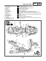
ENGINE REMOVAL
ENG
ENGINE OVERHAUL
ENGINE REMOVAL
COVER REMOVAL
1. Remove :
• Covers
See “CHAPTER 3 - SIDE COVERS AND
FOOTREST BOARD - HANDLEBAR COVER”.
COOLING SYSTEM
1. Drain:
• Coolant
CARBURETOR
1. Remove :
• Air cleaner case assembly Q
2. Disconnect :
• Carburetor cover
• Hoses
• Carburetor top
• Coolant hose on the cylinder head
• Thermostat on the cylinder head
3.Remove :
• Carburetor
4. Remove :
• Muffler assembly
4-1
ENGINE REMOVAL
ENG
5. Loosen :
• Rear wheel fixing bolts
6. Remove:
• Rear wheel
7.Loosen:
• Rear wheel axle nut
8.Remove:
• Rear caliper • Rear wheel collar assembly
CABLES, LEADS AND HOSES
1. Remove :
• Oil hose on the oil pump side
NOTE:
Plug the hose to prevent oil spillage.
2. Disconnect :
• CDI unit lead pump side
• Spark plug cap
• Starter motor lead
• Temperature sender lead on the cylinder head
4-2
ENGINE REMOVAL
ENG
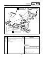
ENGINE REMOVAL
1. Place a suitable stand under the frame.
2. Remove :
• Rear shock absorber bolt (lower) Q
• Engine mounting bolt W
3. Remove :
• Engine
NOTE:
Lift up the frame and remove the engine.
4. Place the frame on a suitable stand.
4-3
ENGINE DISASSEMBLY
ENG
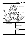
ENGINE DISASSEMBLY
REAR WHEEL
1. Remove :
• Rear wheel
Refer to chapter 7 "REAR WHEEL"
CENTERSTAND
1. Remove :
• Spring • Clip • Plate washer • Axle • Center stand
CYLINDER HEAD AND CYLINDER
1. Remove :
• Cylinder head
• Cylinder head gasket
NOTE:
• Before loosening the cylinder head nuts, loosen
the spark plug.
• Loosen the cylinder head nuts crosswise 1/4 of
a turn each before removing them.
2. Remove :
• Cylinder
• Cylinder gasket
PISTON PIN AND PISTON
1. Remove :
• Piston pin clip Q
NOTE:
Before removing the piston pin clip, cover the
crankcase with a clean rag, so that the clip
cannot accidentally fall into the crankcase.
307001
4-4
ENGINE DISASSEMBLY
ENG
2. Remove :
• Piston pin Q
• Piston W
• Piston pin bearing E
CAUTION:
Do not use a hammer to drive out the
piston pin.
307002
KICKSTARTER
1. Remove :
• Kick crank
• Transmission cover Q (left)
313001
2. Remove :
• Kick pinion gear Q
NOTE:
To remove the kick pinion gear, push down the
kick crank.
3 Unhook :
• Kick return spring W
317001
4. Remove :
• Circlips Q
• Plate washer W
• Kick shaft E
317002
4-5
ENGINE DISASSEMBLY
ENG
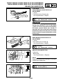
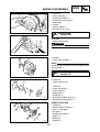
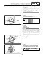
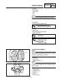
PRIMARY SHEAVE
1. Remove :
• Oil pump housing
2. Remove :
• Nut (primary sheave)
NOTE:
To loosen the primary sheave nut hold the CDI
magneto with a flywheel holder W.
Flywheel holder :
90890-01235
3. Remove :
• Washer Q
• Ratchet W
• Special washer E
• Fixed primary sheave R
• Washer T
• V-belt
319001
4. Remove :
• Spacer Q
• Primary sliding sheave W
319002
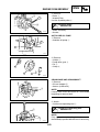
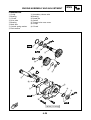
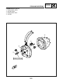
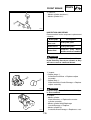
SECONDARY SHEAVE
1. Remove :
• Nut Q (secondary sheave)
NOTE:
Hold the secondary sheave with a sheave holder
W to loosen the nut.
Sheave holder :
90890-01701
319003
4-6
ENGINE DISASSEMBLY
ENG
2. Remove :
• Clutch housing Q
• Secondary sheave W
• Crankcase cover gasket
• Dowel pins
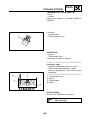
3. Attach :
• Sheave holder Q
• Nut wrench (41 mm)
319004
Sheave holder :
90890-01701
4. Loosen :
• Clutch securing nut
WARNING
Loosen the nut but do not remove it yet.
319031
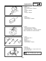
5. Attach :
• Clutch spring holder Q
NOTE:
Compress the secondary sheave using the clutch
spring holder Q.
Clutch spring holder :
90890-01337
311001
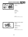
6. Remove :
• Clutch securing nut
7. Remove :
• Clutch assembly Q
• Clutch spring W
• Spring seat E
• Guide pin R
• Secondary sliding sheave T
• Secondary fixed sheave Y
311002
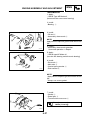
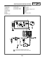
STARTER SYSTEM
1. Remove :
• Starter clutch assembly Q
• Plate W (idle gear)
• Idle gear E
• Starter wheel gear R
• Spacer T
• Bearing Y
• Washer U
317003
4-7
ENGINE DISASSEMBLY
ENG
2. Remove :
• Spacer Q
• Bearing W
• Washer E
• Starter motor
317004
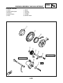
TRANSMISSION
1. Remove :
• Transmission case Q
• Gasket
• Dowel pins
319036
2. Remove :
• Main shaft Q
• Drive shaft W
• Plate washer E
• Conical spring washer R
319037
3. Remove :
• Oil seal Q
• Secondary sheave axle W
319032
CDI MAGNETO
1. Remove :
• Nut Q (rotor)
• Plate washer
NOTE:
Hold the rotor using a flywheel holder W to
loosen the nut.
Flywheel holder :
90890-01235
321004
4-8
ENGINE DISASSEMBLY
ENG
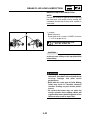
2. Remove :
• Rotor Q
• Woodruff key
Use the flywheel puller W
Flywheel puller :
90890-01189
• Stator assembly
• Gasket
321005
AUTOLUBE OIL PUMP
1. Remove :
• Autolube oil pump Q
314001
2. Remove :
• Circlips Q
• Pump drive gear W
• Pin E
• Circlip R
314002
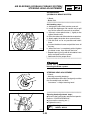
CRANKCASE AND CRANKSHAFT
1. Remove :
• Oil seal stopper • Screws (crankcase)
NOTE:
Loosen each screw one quart of a turn before
beginning to remove them.
2. Attach :
• Crankcase separating tool Q
Crankcase separating tool :
90890-01135
NOTE:
Fully tighten the tool holding bolts. Insure that
the tool body is parallel with the case. If necessary,
313002
4-9
ENGINE DISASSEMBLY
ENG
loosen one screw as much as required to level
the tool body.
3. Remove :
• Crankcase (right)
As pressure is applied, keep tapping carefully on
the engine mounting bosses.
CAUTION:
Use a soft hammer to tap on the case. Tap
only on reinforced spots of the case. Never
tap on the gasket mating surfaces. Work
slowly and carefully. Make sure the cases
separate evenly. If one end “hangs up” take
the pressure off the push screw, realign the
cases and the tool and start again. If the
cases do not separate at all, check for a
remaining case screw or fitting. Do not force.
4. Attach :
• Crankcase separating tool Q
Crankcase separating tool :
90890-01135
5. Remove :
• Crankshaft W
313004
4-10
INSPECTION AND REPAIR
ENG
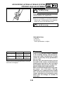
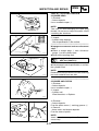
INSPECTION AND REPAIR
CYLINDER HEAD
1. Eliminate :
• Carbon deposits
Use a rounded scraper Q
NOTE:
Take care to avoid damaging the spark plug
threads. Do not use a sharp instrument. Avoid
scratching the aluminum.
301002
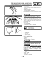
2. Inspect :
• Cylinder head warpage
Out of specification ➞ Re-surface.
*******************************************************
Warpage measurement and re-surfacement
steps :
● Attach a straight edge Q and a thickness
gauge W to the cylinder head.
● Measure the warpage limit.
Warpage limit :
0.02 mm (0.0078 in)
●
If the warpage is out of specification, re-surface
the cylinder head.
301003
NOTE:
Rotate the head several times to avoid removing
too much material from one side.
*******************************************************
CYLINDER AND PISTON
1. Eliminate :
• Carbon deposits
Use a rounded scraper Q
2. Inspect :
• Cylinder wall
Wear/Scratches ➞ Replace.
304001
3. Eliminate :
• Carbon deposits
From the piston crown Q and ring grooves W.
4. Remove :
• Score marks and lacquer deposits
From the sides of piston.
307003
NOTE:
Sand in a crisscross pattern. Do not sand
excessively.
4-11
ENG
INSPECTION AND REPAIR
5. Inspect :
• Piston wall
Wear/Scratches/Damage ➞ Replace.
307004
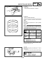
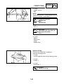
6. Measure :
• Piston to cylinder clearance
********************************************************
Piston to cylinder clearance measurement
steps :
First step :
● Measure the cylinder bore “C” with a cylinder
bore gauge.
D1
D2
D3
D5
NOTE:
Measure the cylinder bore “C” in parallel to and
at right angles to the crankshaft. Then, calculate
the average of the measurements.
D4
D6
Standard
Cylinder
Bore “C”
307005
Taper
"T"
Wear limit
39.99 ~ 40.01mm 40.10 mm
(1.574 ~ 1.575 in) (1.579 in)
_
0,05mm
(0.0019 in)
C = Maximum D
T = (Maximum D1,D3 or D5) (Maximum D2,D4 or D6 )
●
If out of specification, replace cylinder, piston
and piston rings as a set.
2nd step :
● Measure the piston skirt diameter “P” with a
micrometer.
@ 5 mm (0.20 in) from the piston bottom edge.
Piston Size :
Standard :
39.957 ~ 39.977 mm
(1.5731 ~ 1.5738 in)
307006
4-12
INSPECTION AND REPAIR
ENG
●
If out of specification, replace piston and piston
rings as a set.
3rd step :
● Calculate the piston-to-cylinder clearance with
following formula:
Piston-to cylinder clearance =
Cylinder Bore “C” –
Piston Skirt Diameter “P”
● If out of specification, replace cylinder, piston
and piston rings as a set.
Piston-to-cylinder clearance :
0.029 ~ 0.042 mm
(0.0011 ~ 0.0016 in)
Wear limit : 0.1 mm (0.004 in)
*******************************************************
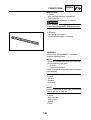
PISTON RINGS
1. Measure :
• Side clearance
Out of specification ➞ Replace piston and/or
rings.
Use a Feeler Gauge Q
Standard
Limit
307007
a
Top
ring
0.03 ~ 0.05 mm
(0.0012 ~ 0.0020 in)
0.10 mm
(0.004 in)
2nd
ring
0.03 ~ 0.05 mm
(0.0012 ~ 0.0020 in)
0.10 mm
(0.004 in)
2. Install :
• Piston ring
• Into the cylinder
Push the ring with the piston crown.
307008
3. Measure :
• End gap
Out of specification ➞ Replace rings as a set.
Use a Feeler Gauge Q
4-13
INSPECTION AND REPAIR
ENG
Standard
Limit
Top
ring
0.15 ~ 0.30 mm
(0.005 ~ 0.011 in)
0.70 mm
(0.028 in)
2nd
ring
0.15 ~ 0.30 mm
(0.005 ~ 0.011 in)
0.70 mm
(0.028 in)
@ Measuring Point 20 mm (0.8 in)
PISTON PIN AND PISTON PIN BEARING
1. Inspect :
• Piston pin
Blue discoloration/Groove ➞ Replace, then
inspect lubrication system.
2. Measure :
• Outside diameter (piston pin)
Out of specification ➞ Replace.
a
Outside diameter (piston pin) :
9.996 ~ 10.000 mm
(0.3935 ~ 0.3937 in)
307009
3. Measure :
• Piston pin-to-piston clearance
Out of specification ➞ Replace piston.
b
Piston pin-to-piston clearance =
Bore (piston pin) b Outside diameter (piston pin) a
307010
Piston pin-to-piston clearance :
0.004 ~ 0.019 mm
(0.0002 ~ 0.0008 in)
<Limit : 0.07 mm (0.028 in)>
4. Inspect :
• Bearing (piston pin)
Pitting/Damage ➞ Replace
307011
4-14
INSPECTION AND REPAIR
ENG
KICK STARTER
1. Inspect :
• Kick gear teeth Q
• Kick pinion gear teeth W
Burrs/Chips/Roughness/Wear ➞ Replace.
317005
2. Inspect :
• Mating dogs (kick pinion gear and one-way
clutch)
Rounded edges/Damage ➞ Replace.
317006
3. Measure :
• Clip tension (kick pinion gear) Q
Out of specification ➞ Replace.
Use a spring balance W.
Standard tension :
150 ~ 250 g (5.3 ~ 8.8 oz.)
317007
TRANSMISSION
1. Inspect :
• Drive axle Q
• Main axle W
• Secondary sheave axle E
Burrs/Chips/Roughness/Wear ➞ Replace.
319005
2. Inspect :
• Secondary sheave axle bearing Q
• Main axle bearing W
• Drive axle bearing E
Spin the bearing inner race.
Excessive play/Roughness ➞ Replace.
Pitting/Damage ➞ Replace.
319038
4-15
INSPECTION AND REPAIR
ENG
AUTOLUBE PUMP
Wear or an internal malfunction may cause the
pump output to vary from the factory setting.
This situation is, however, extremely rare. If
improper output is suspected, inspect the
following:
1. Inspect :
• Delivery line
Obstructions ➞ Blow out.
• O-ring
Wear/Damage ➞ Replace.
2. Inspect :
• Autolube pump drive gear teeth Q
• Autolube pump driven gear teeth W
Pitting/Wear/Damage ➞ Replace.
314003
CRANKSHAFT
1. Measure :
• Crankshaft width "A"
• Runout limit “C”
• Connecting rod big end side clearance “D”
Use V-blocks, dial gauge and thickness gauge.
Crankshaft width "A" :
37.90 ~ 37.95 mm
(1.492 ~ 1.494 in)
Runout limit “C” :
0.03 mm (0.0012 in)
Connecting rod big end side
clearance “D” :
0.2 ~ 0.5 mm (0.008 ~ 0.02 in)
308001
PRIMARY SHEAVE
1. Inspect :
• Primary sliding sheave Q
• Primary fixed sheave W
Wear/Cracks/Scratch/Damage ➞ Replace.
319006
4-16
INSPECTION AND REPAIR
ENG
2. Check :
• Free movement
Insert the collar W into the primary sliding sheave
Q, and check for free movement.
Stick or excessive play ➞ Replace the sheave
and/or collar.
319007
3. Measure :
• Outside diameter Q (weight)
Out of specification ➞ Replace.
Outside diameter (weight) :
15.0 mm (0.59 in)
<Limit>:
14.5 mm (0.57 in)>
319008
SECONDARY SHEAVE
1. Inspect :
• Secondary fixed sheave Q
• Secondary sliding sheave W
Scratch/Crack/Damage ➞ Replace as a set.
• Oil seal E
Damage ➞ Replace.
319009
2. Inspect :
• Torque cam groove Q
• Guide pin W
Wear/Damage ➞ Replace as a set.
• O-rings E
Damage ➞ Replace.
319010
3. Measure :
• Clutch spring free length
Out of specification ➞ Replace.
Clutch spring free length :
121.7 mm (4.79 in)
<Limit> :
106.7 mm (4.20 in)
319011
4-17
INSPECTION AND REPAIR
ENG
4. Inspect :
• Clutch housing inner surface
Oil/Scratches ➞ Remove.
Oil
Use a rag soaked in lacquer
thinner or solvent.
Scratches
Use an emery cloth (lightly
and evenly polishing).
319030
5. Measure :
• Clutch housing inside diameter @
Out of specification ➞ Replace.
Clutch housing inside diameter :
107.0 mm (4.21 in)
<Wear Limit> :
107.4 mm (4.22 in)
319012
6. Inspect :
• Clutch shoes
Glazed parts ➞ Sand with coarse sandpaper.
NOTE:
After using the sand paper, clean off the polished
particles with a cloth.
7. Measure :
• Clutch shoe thickness @
Out of specification ➞ Replace.
Clutch shoe thickness :
2.0 mm (0.07 in)
<Wear Limit> :
1 mm (0.03 in)
319013
V-BELT
1. Inspect :
• V-belt
Crack/Wear ➞ Replace.
NOTE:
Replace the V-belt if it is greasy or oily.
4-18
INSPECTION AND REPAIR
ENG
2. Measure :
• V-belt width @
Out of specification ➞ Replace.
V-Belt width :
16,5 mm (0.65 in)
<Wear Limit> :
15,7 mm (0.62 in)
312001
STARTER CLUTCH AND GEARS
1. Inspect :
• Starter clutch
Push the dowel pin in arrow direction.
Unsmooth operation ➞ Replace starter clutch
assembly.
317008
2. Inspect :
• Starter wheel gear teeth Q
• Idle gear teeth W
Burrs/Chips/Roughness/Wear ➞ Replace.
• Bearing E (starter wheel gear)
Pitting/Damage ➞ Replace.
317009
4-19
ENG
ENGINE ASSEMBLY AND ADJUSTMENT
CRANKSHAFT AND CRANKCASE
Q Oil seal
I Crankshaft pin
W Oil seal holder
O Connecting rod
E Crankcase (right)
P Crankshaft (left)
R Dowel pin
{ Bearing
T Bearing
} Engine mount shaft
Y Crankshaft (right)
q Crankcase (left)
U Bearing
w Oil seal
A CRANKSHAFT:
C
8 Nm (0.8 m.kg)
A:
C:
D:
E:
13 Nm (1.3 m.kg)
37,90 ~ 37,95 mm
0,03 mm
0,2 ~ 0,5 mm
0,004 ~ 0,017 mm
C
E
D
A
LS
E
E
E
LS
17,5 Nm (1.75 m.kg)
4-20
ENGINE ASSEMBLY AND ADJUSTMENT
ENG
CRANKSHAFT AND CRANKCASE
CAUTION:
To protect the crankshaft against scratches
and to facilitate the engine assembly and
installation, apply grease to oil seal lips,
and engine oil to bearings.
1. Attach :
• Crankshaft installation tool Q, W, E, R
Crankshaft installation tool :
Q : 90890-01274
W : 90890-01275
E : 90890-01277
R : 90890-01411
308002
2. Install :
• Crankshaft
(to left crankcase)
NOTE:
Hold the connecting rod at top dead center with
one hand while tightening the nut of the
installation tool with the other. Tighten the
installation tool until the crankshaft bottoms
against the bearing.
3. Install :
• Dowel pins • Spacer 313005
4. Apply :
• HEATPROOF or Yamaha Bond No.1215
To the mating surfaces of both case halves.
HEATPROOF or Yamaha Bond
No.1215
313006
4-21
ENGINE ASSEMBLY AND ADJUSTMENT
ENG
5. Attach :
• Crankshaft installation tool Q, W, E, R
Crankshaft installation tool :
Q : 90890-01274
W : 90890-01275
E : 90890-01277
R : 90890-01411
313007
NOTE:
Hold the connecting rod at top dead center with
one hand while tightening the nut of the
installation tool with the other. Tighten the
installation tool until the crankcase halves close
with one another.
6. Install :
• Right crankcase
7. Tighten :
• Crankcase holding screws
NOTE:
Tighten the crankcase holding screws in stages,
using a crisscross pattern.
T.
R
Crankcase holding screw :
15 Nm (1,5 m.kg)
313009
8. Check :
• Crankshaft operation
Unsmooth operation ➞ Repair.
CAUTION:
Never hit on the crankshaft.
308003
9. Install :
• Oil seal stopper plate
T.
R
313009
4-22
Screw (oil seal stopper plate) :
8 Nm (0.8 m.kg)
ENG
ENGINE ASSEMBLY AND ADJUSTMENT
AUTOLUBE PUMP AND CDI MAGNETO
O Gasket
Q Nut
P Oil hose
W Plain washer
{ Oil delivery hose
E Rotor assembly
} Clip
R Lighting coil
q Autolube pump
T Charge coil
w O-ring
Y Pick up coil
e Circlip
U Stator assembly
r Oil pump drive gear
I Oil seal
37.5 Nm (3.75 m.kg)
LS
8.5 Nm (0.85 m.kg)
LS
4 Nm (0.4 m.kg)
4-23
ENGINE ASSEMBLY AND ADJUSTMENT
ENG
AUTOLUBE PUMP
1. Install :
• Circlip Q
• Pin W
• Pump drive gear E
• Circlip R
314004
2. Apply :
• Lithium soap base grease
(to O-ring )
3. Install :
• Autolube pump
T.
R
314005
Screw (autolube pump) :
4 Nm (0.4 m.kg)
4. Apply :
• Lithium soap base grease
(to autolube pump gear)
Lithium soap base grease :
15 cc (0.92 cu.in)
314006
CDI MAGNETO
1. Install :
• Gasket
2. Apply :
• Lithium soap base grease
(to oil seal Q)
321001
3.Pass the CDI magneto lead through the
crankcase hole.
4. Install :
• Stator assembly
T.
R
4-24
Screw (stator assembly) :
8,5 Nm (0.85 m.kg)
ENGINE ASSEMBLY AND ADJUSTMENT
5. Install :
• Woodruff key Q
• Magneto rotor W
• Plain washer E
• Nut R
321002
ENG
NOTE:
When installing the magneto rotor, make sure
the woodruff key is properly seated in the key
way of the crankshaft. Apply a light coating of
lithium soap base grease to the tapered portion
of the crankshaft end.
6. Tighten :
• Nut Q (magneto rotor)
Use the flywheel holding tool W.
Flywheel holding tool :
90890-01235
T.
R
321004
4-25
Nut (Flywheel magneto) :
37,5 Nm (3.75 m.kg)
ENG
ENGINE ASSEMBLY AND ADJUSTMENT
TRANSMISSION
Q Circlip
W Bearing
E Oil seal
R Drive axle
T Bearing
Y Main axle
U Conical spring washer
I Plain washer
O Secondary sheave axle
P Bearing
{ Dowel pin
} Gasket
q Transmission case cover
w Circlips
e Oil seal
E
LS
E
G
G
LT
LS
10 Nm (1.0 m.kg)
4-26
ENGINE ASSEMBLY AND ADJUSTMENT
ENG
TRANSMISSION
1. Apply :
• 10W30 Type SE Motor oil
(to transmission case cover bearing)
2. Install :
• Bearing Q
3. Install :
• Oil seal W
• Secondary sheave axle E
NOTE:
Apply lithium soap base grease onto the oil seal
lips.
319014
4. Check :
• Secondary sheave axle operation
Unsmooth operation ➞ Repair.
5. Apply :
• 10W30 type SE Motor oil
(to main axle bearing and drive axle bearing)
6. Install :
• Drive axle Q
• Main axle W
• Conical spring washer E
• Plain washer R
319016
NOTE:
• Apply lithium soap base grease onto the oil seal
lips.
• Always use a new gasket.
7. Install :
• Gasket Q
• Dowel pins W
• Transmission case cover E
T.
R
319017
4-27
Screw (case cover):
10 Nm (1.0 m.kg)
ENGINE ASSEMBLY AND ADJUSTMENT
STARTER SYSTEM
Q Collar
W Starter wheel gear
E Bearing
R Starter clutch
T Plate
ENG
Y Shaft
U Washer
I Idle gear
O O-Ring
P Starter motor
LS
M
8 Nm (0.8 m.kg)
E
13 Nm (1.3 m.kg)
LS
4-28
ENGINE ASSEMBLY AND ADJUSTEMENT
ENG
STARTER SYSTEM
1. Install :
• Collar Q
• Washer W
• Bearing E
• Starter wheel gear R
• Starter clutch T
317010
NOTE:
• Apply lithium soap base grease to the bearing.
• Apply molybdenum disulfide oil to the shaft
(starter clutch).
317011
2. Install :
• Plain washer Q
• Idle gear W
• Plain washer E
• Plate R (idle gear)
T.
R
Screw (idle gear plate) :
8 Nm (0.8 m.kg)
317012
NOTE:
Apply engine oil to the idle gear W.
3. Install :
• Starter motor Q
T.
R
317013
Screw (starter motor) :
13 Nm (1.3 m.kg)
NOTE:
Apply lithium soap base grease to the O-ring of
the starter motor.
4-29
ENG
ENGINE ASSEMBLY AND ADJUSTMENT
PRIMARY AND SECONDARY SHEAVE
Q Nut
} Secondary fixed sheave
W Clutch housing
q Conical washer
E Clutch
w One-way clutch
R Clutch spring
e Special washer
T Spring
r Primary fixed sheave
Y Spring seat
t Washer
U Oil seal
y Spacer
I O-Ring
u Primary sliding sheave
O Secondary sliding sheave i Clutch weights
P V-Belt
o Slider
{ Guide pin
p Came
*Apply BEL-RAY Assembly Lube ©
50 Nm (5.0 m.kg)
LS
30 Nm (3.0 m.kg)
A
B
C
D
E
Clutch shoe spring free lenght: 29.9 mm
Clutch housing wear limit: 107.4 mm
Clutch shoes wear limit: 1.0 mm
V-belt wear limit: 15.7 mm
Weight outside diameter wear limit: 14.5 mm
22
21
*
33 Nm (3.3 m.kg)
4-30
ENG
ENGINE ASSEMBLY AND ADJUSTMENT
KICK STARTER
Q Kick shaft
W Return spring
E Collar
R Gasket
T Transmission case
Y Washer
U Circlips
I Kick crank
O Kick clip
P Rachet
G
12 Nm (1.2 m.kg)
LS
150 ~ 250 g
10 Nm (1.0 m.kg)
4-31
ENGINE ASSEMBLY AND ADJUSTEMENT
ENG
SECONDARY SHEAVE
When assembling the secondary sheave, reverse
the disassembly procedure. Note the following
points.
1. Apply :
• BEL-RAY Assembly Lube ®
(to the sliding parts of the sheave)
319018
2. Install :
• Sliding sheave Q
NOTE:
Wind adhesive tape around the end of the sheave
to avoid turning over the oil seal lips when
installing the sheave.
319019
3. Install :
• Pin Q
4. Apply :
• BEL-RAY Assembly Lube ®
(to the torque cam grooves and O-rings)
319020
5. Check :
• Sliding sheave
Unsmooth operation ➞ Repair.
CAUTION:
Remove excessive grease.
6. Install :
• Clutch securing nut
Use the clutch spring holder Q
Clutch spring holder :
90890-01337
319021
7. Tighten :
• Clutch securing nut
Use sheave holder Q (41mm).
Sheave holder :
90890-01701
T.
R
319031
4-32
Clutch securing nut :
50 Nm (5.0 m.kg)
ENGINE ASSEMBLY AND ADJUSTEMENT
ENG
8. Install :
• Dowel pin
• Gasket
• Secondary sheave assembly Q
• Clutch housing W
319022
9. Tighten :
• Nut Q (secondary sheave)
Use sheave holder W
Sheave holder :
P/N. 90890-01701
R
Nut (secondary sheave) :
30 Nm (3.0 m.kg)
PRIMARY SHEAVE
1. Clean :
• Primary sliding sheave face Q
• Primary fixed sheave face W
• Collar E
• Weight R
• Primary sliding sheave cam surface T
T.
319023
319024
319025
2. Install :
• Weight Q
• Cam W
• Slider E
• Collar R
3.Check :
• Cam operation
Unsmooth operation ➞ Repair.
4. Install :
• Primary sheave assembly Q
• Collar W
319026
4-33
ENGINE ASSEMBLY AND ADJUSTEMENT
ENG
5. Install :
• V-belt
Place the V-belt around the secondary sheave,
and compress the secondary sheave spring
hard so that the V-belt moves toward the clutch
hub.
NOTE:
• The arrow on the V-belt must point to the front.
• Make sure the V-belt is not stained with oil or
grease.
6. Install :
• Shim Q
• Primary fixed sheave W
• Washer E
• One-way clutch R
• Washer T
• Nut Y
319027
7. Tighten :
Nut (primary sheave)
T.
R
Nut (primary sheave) :
33 Nm (3.3 m.kg)
NOTE:
When tightening the nut (primary sheave), hold
the magneto rotor using the flywheel holding
tool.
Flywheel holding tool :
90890-01235
8. Adjust :
• V-belt
Tense the V-belt by turning the primary sheave
several times.
4-34
ENGINE ASSEMBLY AND ADJUSTEMENT
ENG
9. Install :
• Fan
T.
R
Screw (fan) :
7 Nm (0.7 m.kg)
KICK STARTER
1. Install :
• Return spring Q
• Kick shaft W
• Collar E
• Washer R
• Circlip T
317014
2. Hook :
• Return spring
(to the kick gear and boss)
3. Install :
• Kick pinion gear Q
NOTE:
Install the clamp as shown.
317015
4. Install :
• Transmission case Q
T.
R
Screw (Transmission case) :
12 Nm (1.2 m.kg)
319029
5. Install :
• Kick crank Q
T.
R
317016
4-35
Bolt (kick crank) :
10 Nm (1.0 m.kg)
ENG
ENGINE ASSEMBLY AND ADJUSTMENT
PISTON, CYLINDER AND CYLINDER HEAD
Q Carburetor joint
U Cylinder gasket
W Reed valve
I Piston ring
E Gasket
O Piston
R Cylinder head
P Piston pin
T Cylinder head gasket
{ Piston pin clip
Y Cylinder
} Bearing
A Piston clearance:
0.029 ~ 0.042 mm
B Piston rings end gap:
0.15 ~ 0.35 mm
C Piston rings side clearance:
0.03 ~ 0.05 mm
D Spark plug:
Type: BR8HS
Manufacturer: NGK
11 Nm (1.1 m.kg)
4 Nm (0.4 m.kg)
16 Nm (1.6 m.kg)
LT
20 Nm (2.0 m.kg)
14 Nm (1.4 m.kg)
4-36
ENGINE ASSEMBLY AND ADJUSTEMENT
ENG
PISTON PIN AND PISTON
1. Apply :
• Engine oil
(to crankshaft bearing, connecting rod big end
bearing, small end bearing, piston pin, piston
ring grooves and piston skirt .)
2. Install :
• Small end bearing
• Piston Q
• Piston pin E
• Piston pin clip R
307012
NOTE:
• The arrow W on the piston must point to the
exhaust side.
• Before installing the piston pin clip, cover the
crankcase with a clean towel or rag so you will
not accidentally drop the pin clip and material
into the crankcase.
CAUTION:
• The ends of the piston pin clip must not
come together at the slot in the piston
groove.
• Always use new piston pin clip.
CYLINDER AND CYLINDER HEAD
1. Install :
• Cylinder gasket (new gasket)
2. Check :
• Piston rings
307013
NOTE:
• Make sure the ring ends Q are properly fitted
around the ring locating pins in the piston grooves.
• Be sure to check the manufacturer’s marks or
numbers stamped on the rings are on the top
side of the rings.
4-37
ENGINE ASSEMBLY AND ADJUSTEMENT
ENG
3. Install :
• Cylinder
NOTE:
Install the cylinder with one hand, while
compressing the piston rings with the other
hand.
4. Install :
• Cylinder head gaskets (new gaskets)
5. Install :
• Cylinder head • Spark plug • Thermostat NOTE:
• Tighten the cylinder head holding nuts in stages,
and crisscross sequence.
• The arrow on the cylinder head must point to
the front.
T.
R
Nut (cylinder head) :
14 Nm (1.4 m.kg)
Spark plug :
20 Nm (2.0 m.kg)
Thermostat :
16 Nm (1.6 m.kg)
6. Install :
• Center stand
• Axle • Plate washer • Clip • Spring 7. Install :
• Rear wheel
Refer to chapter 8 "REAR WHEEL"
4-38
ENGINE ASSEMBLY AND ADJUSTEMENT
ENG
8. Install :
• Oil hose
• Oil delivery hose
ENGINE REMOUNTING
Reverse the removal procedure.
Note the following points.
1. Install :
• Engine mounting bolt 2
• Rear shock absorber bolt 1 (lower)
These bolts should be temporarily secured.
2. Tighten :
• Engine mounting bolt
• Rear shock absorber bolt (lower)
T.
R
Engine mounting bolt :
50 Nm (5.0 m.kg)
Rear shock absorber bolt (lower) :
16 Nm (1.6 m.kg)
3. Install :
• Carburetor top together with throttle valve Q
• Fuel hose W/Vacuum hose E
• Brake cable/plug cap
4. Connect:
• Water hoses
322032
NOTE:
When installing the throttle valve into the
carburetor, align the groove of the throttle valve
with the projection of the carburetor.
5. Connect :
• Starter motor
• CDI magneto lead
• Earth
6. Install:
• Rear wheel collar assembly
NOTE:
Make sure the splines on the wheel hub fit onto
the rear drive axle.
7. Tighten :
• Rear wheel axle nut Q
NOTE:
When tightening the rear wheel axle nut, apply
the rear brake.
4-39
ENGINE ASSEMBLY AND ADJUSTEMENT
T.
R
ENG
Rear wheel axle nut :
120 Nm (12 m.kg)
8.Install:
• Rear wheel
9.Tighten:
• Rear wheel fixing bolt
T.
R
Rear wheel fixing bolt:
47 Nm (4.7 m.kg)
10. Install :
• Muffler assembly
T.
R
Bolt (muffler) :
26 Nm (2.6 m.kg)
Bolt (exhaust pipe) :
9 Nm (0.9 m.kg)
11. Fill :
• Transmission oil
Refer to “CHAPTER 3 – TRANSMISSION OIL
REPLACEMENT” section.
12. Fill:
• Radiator
Refer to “CHAPTER 5– "COOLING SYSTEM”
section.
13. Adjust :
• Brake lever free play
Refer to “CHAPTER 3 – FRONT/REAR BRAKE
LEVER FREE PLAY ADJUSTMENT” section.
• Engine idle speed
• Throttle cable free play
Refer to “THROTTLE CABLE FREE PLAY
ADJUSTMENT” and “ENGINE IDLE SPEED
ADJUSTMENT”.
COOLING SYSTEM
1.Install :
• Coolant hose.
CAUTION :
Align the mark onthe coolant hose with the
mark on the water pump housing
4-40
COOL
5
COOL
CHAPTER 5.
COOLING SYSTEM
RADIATOR ..................................................................................................... 5-1
REMOVAL ................................................................................................ 5-2
INSPECTION ........................................................................................... 5-2
INSTALLATION ........................................................................................ 5-2
WATER PUMP ............................................................................................... 5-3
REMOVAL ................................................................................................ 5-4
INSPECTION ........................................................................................... 5-4
INSTALLATION ........................................................................................ 5-4
THERMOSTATIC VALVE .............................................................................. 5-5
REMOVAL ................................................................................................ 5-6
INSPECTION ........................................................................................... 5-6
INSTALLATION ........................................................................................ 5-6
COOL
COOLING SYSTEM
RADIATOR
Q Coolant tank cap
W Coolant tank
E Radiator
R Hose
T Water pump
Y O-Ring
햲
U Impeller O-Ring
I Cylinder Head
O Cylinder
P Thermostatic valve
{ Thermo switch
햳
7 Nm (0.7 m.kg)
햶
햷
햵
햸
햴
햺
햻
햵
햹
LT
LT
햽
16 Nm (1.6 m.kg)
5-1
COOLING SYSTEM
COOL
COOLING SYSTEM
RADIATOR REMOVAL
1.Remove:
• Air filter
• Carburetor assembly
Refer to chepter 6 "CABURETOR"
2.Drain:
• Radiator
Refer to chapter 3 "COOLANT REPLACEMENT"
3.Remove:
• Hose
• Radiator assembly.
INSPECTION
1.Inspect:
• Radiator core
Obstruction → Blow out with compressed air
through rear of the radiator.
Flattened fin → Repair/Remplace.
2.Inspect:
• Radiator hoses
Cracks/Damage → Replace
3.Inspect:
• Coolant tank
Cracks/Damage → Replace
INSTALLATION
Reverse the "REMOVAL" procedure.
Refer to the chapter 2 " CABLE ROUTING"
5-2
COOLING SYSTEM
WATER PUMP
Q Water pump housing
W O-Ring
E Impeller
R Seal
T Cover
Y Bearing
U Spacer
COOL
I Bearing
O Rotor
P Circlips
{ Rubber
} Driving plug
q Washer
햲
햳
햴
7 Nm (0.7 m.kg)
햵
햶
햷
햸
햹
햺
LS
6.5 Nm (0.65 m.kg)
6.5 Nm (0.65 m.kg)
5-3
햻
햽
햾
햿
COOLING SYSTEM
COOL
WATER PUMP REMOVAL
1.Remove:
• Side cover
Refer to chapter 3 "COVER"
2.Drain:
• Radiator
• Hoses
Refer to chapter 3 "COOLANT REPLACEMENT"
3.Remove:
• Water pump fixing bolds
• Water pump
• Hoses
INSPECTION
1.Inspect:
• Impeller 햲
Used/Damaged → Replace
Scale deposit → Clean
햲
2.Inspect:
• Rotor
Used/Damaged → Replace
INSTALLATION
Reverse the "REMOVAL" procedure.
Note the following points.
NOTE:
• It is no necessary to remove and inspect the
water pump if the coolant is not unsually low
or if it has no engine oil mixed in it.
• Always replace the entire water pump as a set.
1.Apply:
• Lithium soap base grease (to the seal)
2.Install:
• Water pump assembly
• Side cover
CAUTION :
Align the mark on the hoses with the mark on
the water pump housing.
5-4
COOL
COOLING SYSTEM
THERMOSTATIC VALVE
Q Thermostatic switch
W Cylinder head
E Thermostatic valve
R Cylinder
햵
햴
햳
LT
LT
햲
16 Nm (1.6 m.kg)
5-5
COOLING SYSTEM
COOL
THERMOSTATIC VALVE REMOVAL
1.Drain:
• Coolant
Refer to the chapter 3 "COOLANT REMPLACEMENT"
2.Remove:
• Cylinder head
• Thermostatic valve 햲
햲
INSPECTION
1.Inspect:
• Thermostatic valve
Valve does not open → Replace
햴
*******************************************************
Inspection steps:
• Suspend thermostatic valve in a vessel.
• Place reliable thermometer in a water.
• Observe thermometer, while stirring water
continually.
********************************************************
햲 Thermostatic valve
햳 Vessel
햴 Thermometer
햵 Water
햲
햵
햳
INSTALLATION
Reverse the "REMOVAL" procedure.
Thermostat valve screws:
5Nm (0.5 m.kg)
5-6
CARB
6
CARB
CHAPTER 6.
CARBURETION
CARBURETOR .............................................................................................. 6-1
DELL'ORTO CARBURETOR ................................................................... 6-1
REMOVAL ................................................................................................ 6-2
DISASSEMBLY ........................................................................................ 6-2
INSPECTION ........................................................................................... 6-3
ASSEMBLY .............................................................................................. 6-5
INSTALLATION ........................................................................................ 6-6
FUEL COCK ................................................................................................... 6-7
INSPECTION ........................................................................................... 6-7
REED VALVE ................................................................................................. 6-7
REMOVAL ................................................................................................ 6-7
INSPECTION ........................................................................................... 6-8
INSTALLATION ........................................................................................ 6-9
CARBURETOR
DELL'ORTO CARBURETOR
Q Carburetor top
W Gasket
E Throttle valve spring
R Needle set
T Throttle valve
Y Starter plunger spring
U Starter plunger
I Air screw
O Throttle stop screw
CARB
P Pilot jet
{ Needle jet
} Needle valve
q Main jet
w Float pin
e Float
r Float chamber gasket
t Float chamber
y Drain screw
햲
햳
햴
햷
햶
햸
햵
햺
햹
햽
햿
햻
헁
햾
헀
헂
헃
헄
322034
6-1
CARBURETOR
CARB
REMOVAL
1. Remove :
• Side covers and footrest board
Refer to the section “SIDE COVERS AND
FOOTREST BOARD” in Chapter 3.
• Air filter case assembly
2.Drain:
• Coolant
Refer to chapter 3 "COOLANT REPLACEMENT"
3. Disconnect :
• Fuel hose
• Oil hose
• Coolant hoses
4. Remove :
• Carburetor top
• Throttle valve
• Starter plunger top
• Starter plunger
• Carburetor
DISASSEMBLY
1. Remove :
• Float chamber Q
햲
322007
햳
2. Remove :
• Float pin Q
• Float W
• Needle valve E
햴
햲
322026
6-2
CARBURETOR
3. Remove :
• Pilot jet Q
• Main jet W
• Main nozzle E
• Starter jet R
햳
햲
CARB
햴
햵
322027
햲
4. Remove :
• Throttle stop screw Q
• Spring (throttle stop screw)
• Air screw W
• Spring (air screw)
햳
322028
5. Remove :
• Needle clip Q
• Jet needle W
• Throttle valve E
햲
햳
햴
322029
INSPECTION
1. Check :
• Carburetor body Q
Dirt ➞ Clean.
햲
NOTE:
Use a petroleum based solvent for cleaning.
Blow out all passages and jets with compressed
air.
322006
2. Inspect :
• Main jet Q
• Main nozzle W
• Pilot jet E
• Starter jet
Contamination ➞ Clean.
햳
햲
햴
322012
6-3
CARBURETOR
3. Check :
• Needle valve Q
Wear/Contamination ➞ Replace.
• Float W
Damage ➞ Replace.
• Gasket
Damage ➞ Replace.
햳
햲
CARB
322013
4. Check :
• Throttle valve Q
Wear/Damage ➞ Replace.
햲
322014
햲
5. Check :
• Throttle valve free movement
Unsmooth/stickiness ➞ Replace.
Insert the throttle valve Q into the carburetor
body W and check for smooth movement.
햳
322015
햲
6. Check :
• Throttle stop screw Q
• Air screw W
• Needle E
• Starter plunger R
Wear/Damage ➞ Replace.
햳
햴
햵
322016
7. Measure :
• Float height @
Out of specification ➞ Inspect needle valve,
float, and valve seat.
a
Float height @ :
15.0 ~ 17.0 mm (0.59 ~ 0.67 in)
322017
6-4
CARBURETOR
CARB
******************************************************
Float height measurement steps :
• Install the needle valve, float and float pin into
the carburetor body.
• Hold the carburetor upside down.
• Measure the height distance between the mating
surface of the float chamber (gasket removed)
and the top of the float, using a gauge.
NOTE:
The float arm should be resting on the needle
valve. It should not compress the needle valve.
• If the float height is not within specification,
inspect the needle valve, float and valve seat.
• If one of these parts is worn, replace the whole
set.
• If both parts are in good condition, replace the
float.
• Check the float height again.
********************************************************
NOTE:
The float height is factory-adjusted. Never try to
adjust it yourself.
ASSEMBLY
Reverse the “DISASSEMBLY” procedures. Note
the following points.
CAUTION:
• Before reassembling the carburetor wash
all its components in clean gasoline.
• Always use new gaskets.
햳
햴
1. Install :
• Needle W
• Clip E
• Throttle valve Q
• Spring seat R
• Spring
햵
햴
햳
햲
Jet needle clip position :
See specifications on Chapter 2
322018
6-5
CARBURETOR
햲
햳
CARB
2. Install :
• Throttle valve Q
• Starter plunger
NOTE:
Align the groove W of the throttle valve with the
projection E of the carburetor body.
햴
322019
3. Install :
• Carburetor
햲
NOTE:
Align projection Q with projection W.
햳
322020
INSTALLATION
To install the carburetor reverse the “REMOVAL” procedures. Note the following points.
1. Install :
• Carburetor cover
2.Connect:
• Coolant hose.
3. Adjust :
• Throttle cable free play
Refer to the section “THROTTLE CABLE FREE
PLAY ADJUSTMENT” in Chapter 3.
4. Install :
• Air filter case 햲
5.Fill:
• Coolant.
Refer to the chapter
REPLACEMENT"
햲
6-6
3
"COOLANT
FUEL COCK/
FUEL FILTER CLEANING/
REED VALVE
CARB
FUEL COCK
INSPECTION
1. Stop the engine.
2. Remove :
• Side covers
Refer to the section “SIDE COVERS AND
FOOTREST BOARD” in Chapter 3.
3. Check :
• Fuel cock
********************************************************
Fuel cock inspection steps :
● Disconnect the fuel hose.
● Place a receptacle under the fuel hose end.
● If fuel stops flowing within a few seconds, the
fuel cock is in good condition. If not clean or
replace the fuel cock.
● Disconnect the vacuum hose and breathe in
through the hose to create a vacuum in the fuel
cock.
If fuel flows out of the fuel hose when vacuum is
applied and stops flowing when vacuum stops,
the fuel cock is in good condition.
If not, clean or replace the vacuum hose, the fuel
hose and the fuel cock.
********************************************************
FUEL FILTER CLEANING
The fuel filter is fitted inside the fuel tank. It is
accessible when the fuel hose (between the fuel
tank and the fuel cock) is disconnected.
Refer to the chapter 2 "CABLE ROUTING" for
proprer installation.
REED VALVE
REMOVAL
1. Remove :
• Side covers
Refer to the section “SIDE COVERS AND
FOOTREST BOARD” in Chapter 3.
2. Remove :
• Carburetor
Refer to section “CARBURETOR REMOVAL”.
6-7
REED VALVE
CARB
3. Remove :
• Carburetor joint
• Reed valve assembly
INSPECTION
1. Check :
• Carburetor joint
Damage/Cracks ➞ Replace.
• Reed valve
Wear/Cracks/Damage ➞ Replace.
*********************************************************
Reed valve inspection steps :
● Visually inspect the reed valve.
NOTE:
A reed valve in good condition should be
completely or at least nearly flush with the valve
seat.
● If in doubt, apply suction to the carburetor side
of the assembly.
● Leakage should be minimal to moderate.
*********************************************************
2. Measure :
• Valve stopper height Q
Out of specification ➞ Replace valve stopper.
햲
Valve stopper height :
6,0 ~ 6,4 mm (0.23 ~ 0.25 in)
322023
3. Measure :
• Reed valve clearance Q
Out of specification ➞ Replace reed valve.
햲
Reed valve clearance :
Less than 0.2 mm (0.008 in)
322024
6-8
REED VALVE
CARB
INSTALLATION
To install the reed valve reverse the “REMOVAL” procedure. Note the following points.
1. Install :
• Gasket (new)
2. Tighten :
• Reed valve assembly bolts
T.
R
Reed valve assembly bolts :
9 Nm (0.9 m.kg)
NOTE:
Tighten the screws crosswise in several steps to
prevent warpage of the read valve assembly and
the carburetor joint.
6-9
CHAS
7
CHAS
CHAPTER 7.
CHASSIS
FRONT WHEEL ............................................................................................. 7-1
REMOVAL ................................................................................................ 7-2
INSPECTION ........................................................................................... 7-2
INSTALLATION ........................................................................................ 7-3
FRONT BRAKE .............................................................................................. 7-4
BRAKE PAD REPLACEMENT ................................................................. 7-6
CALIPER DISASSEMBLY ....................................................................... 7-7
MASTER CYLINDER DISASSEMBLY ..................................................... 7-8
INSPECTION AND REPAIR .................................................................... 7-9
CALIPER ASSEMBLY ........................................................................... 7-10
MASTER CYLINDER ASSEMBLY ......................................................... 7-11
REAR WHEEL ............................................................................................. 7-13
REAR MASTER CYLINDER .................................................................. 7-14
REMOVAL .............................................................................................. 7-15
INSPECTION .........................................................................................7-15
ASSEMBLY ............................................................................................ 7-16
INSTALLATION ...................................................................................... 7-16
FRONT FORK .............................................................................................. 7-17
REMOVAL .............................................................................................. 7-18
DISASSEMBLY ...................................................................................... 7-19
INSPECTION .........................................................................................7-20
ASSEMBLY ............................................................................................ 7-20
INSTALLATION ...................................................................................... 7-21
STEERING HEAD AND HANDLEBAR ........................................................ 7-22
REMOVAL .............................................................................................. 7-23
INSPECTION .........................................................................................7-24
ASSEMBLY AND INSTALLATION ......................................................... 7-25
CHAS
FRONT WHEEL
CHASSIS
FRONT WHEEL
Q Axle
W Speedometer gear
E Bearing
R Collar
T Front rim
Y Tire
U Valve
I Collar
O Spacer
P Nut
A
TIRE SIZE:
130/60 - 13
B
RIM RUNOUT LIMIT:
VERTICAL:
1,0 mm
LATERAL:
1,0 mm
햲
햳
햷
햴
햵
햶
햸
B
LS
햴
햹
B
LS
35 Nm (3.5 m.kg)
7-1
햺
햻
FRONT WHEEL
햲
CHAS
REMOVAL
1. Remove :
• Front caliper fixing bolts
• Front caliper
• Speedometer cable Q
• Axle W
• Front wheel
햳
NOTE:
Never depress the brake lever when the wheel
is off the scooter. Otherwise the brake pads will
be forced out.
340003
INSPECTION
1. Inspect :
• Front axle runout
Out of specification ➞ Replace.
Axle runout limit:
0.25 mm (0.01 in)
340006
WARNING
Do not attempt to straighten a bent axle.
2. Measure :
• Wheel runout
Out of specification ➞ Replace.
Rim runout limit:
Radial: 1.0 mm (0.04 in)
Lateral: 1.0 mm (0.01 in)
340007
3. Inspect :
• Tire
Wear/Cracks/Warpage ➞ Replace.
4. Inspect :
• Wheel bearings
Bearings allow play in the wheel hub or
wheel turns roughly ➞ Replace.
340008
5. Check :
• Speedometer gear Q
Wear/Damage ➞ Replace.
햲
340004
7-2
FRONT WHEEL
CHAS
INSTALLATION
Reverse the “Removal” procedure.
Note the following points.
1.Lubricate :
• Front wheel axle
• Bearings
• Oil seal (lips)
• Drive/driven gear (speedometer)
Recommended lubricant :
Lithium soap base grease
햲
2. Install :
• Speedometer gear unit Q
NOTE:
Be sure that the two projections at the gear unit
mesh with the two slots on the wheel hub.
340004
3. Install :
• Front wheel Q
• Front caliper W
햲
NOTE:
Be sure that the slot (torque stopper) of the gear
unit housing is positioned correctly.
햳
346005
4.Tighten :
• Front wheel axle
• Front caliper mounting bolts
Apply Loctite
LOCTITE®
T.
R
Front wheel axle :
35 Nm (3.5 m.kg)
Front caliper mounting bolts :
23 Nm (2.3 m.kg)
WARNING
Make sure that the brake hoses are routed
properly.
7-3
FRONT BRAKE
FRONT BRAKE
Q Disk
W Bolt
E Caliper
R Piston
T Piston seals
Y Air bleed screw
U
I
O
P
{
}
CHAS
NOTE:
Be sure to install the pads correctly.
Pad spring
Pad retainer
Brake pads
O-Ring
Bolt
Mounting bolt
6 Nm (0.6 m.kg)
A Front brake pad wear limit: 2mm
B Front disk wear limit: 3.2 mm
햷
햻
햾
햴
햶
햵
햸
햵
21 Nm (2.1 m.kg)
햹
햶
햾
LT
햺
햽
LT
23 Nm (2.3 m.kg)
햲
햳
LT
23 Nm (2.3 m.kg)
7-4
FRONT BRAKE
FRONT MASTER CYLINDER
Q Master cylinder
W Master cylinder piston ass'y
E Diaphragm
R Master cylinder cap
T Master cylinder bracket
Y Copper washer
U Union bolt
I Brake hose
O Union bolt
P Front brake switch
{ Front brake lever
CHAS
NOTE:
Drain completely before removing
the master cylinder.
1.5 Nm (0.15 m.kg)
햵
햲
햴
11 Nm (1.1 m.kg)
14 Nm (1.4 m.kg)
햳
햶
23 Nm (2.3 m.kg)
햽
햷
햸
햻
햹
햷
23 Nm (2.3 m.kg)
햺
7-5
FRONT BRAKE
CHAS
WARNING
• Disc brake components rarely require
disassembly. Do not disassemble
components unless absolutely necessary.
If any hydraulic connection is
disconnected, the entire system must be
disassembled, drained, cleaned, and then
properly filled and bleed after reassembly.
Do not use solvents on internal brake
component.
• Solvents will cause seals to swell and
distort. Use only clean brake fluid for
cleaning. Use care with brake fluid. Never
allow brake fluid to come in contact with
the eyes. Brake fluid can damage painted
surfaces and plastic parts.
BRAKE PAD REPLACEMENT
It is not necessary to disassemble the brake
caliper and brake hose to replace the brake
pads.
1. Remove :
• Pin Q
• Axle W
햲
햴
햵
햳
346005
2. Remove :
• Pad spring E
• Brake pads R
NOTE:
Replace the brake pads as a set when either one
is worn to the limit.
3.Measure :
• Brake pads
Out of specification ➞ Replace.
NOTE:
Replace the brake pad and spring as a set when
replacing the brake pads.
햲
Wear limit 햲 :
2 mm (0.078 in)
7-6
FRONT BRAKE
CHAS
4. Install :
• Brake pads
• Pad spring
• Axle
• Pin
NOTE :
Be careful to install the brake pads correctly.
5.Lubricate :
• Mounting bolt (caliper body)
Recommended lubricant :
Lithium soap base grease
6.Install :
• Wheel axle
• Mounting bolt (front caliper)
Apply LOCTITE
LOCTITE ®
T.
R
Wheel axle :
35 Nm (3.5 m.kg)
Mounting bolt :
21 Nm (2.1 m.kg)
CALIPER DISASSEMBLY
NOTE:
Before disassembling the front brake caliper,
drain all brake fluid from the brake hose, master
cylinder, brake caliper and tank.
햲
1.Remove:
• Union bolt Q
• Copper washers W
햳
346005
NOTE:
Place the open end of the drain hose into a
container and pump out the remaining brake
fluid carefully.
햲
2.Remove:
• Caliper body
• Caliper bracket
3. Remove :
• Piston
• Piston seals Q
347004
7-7
FRONT BRAKE
CHAS
*******************************************************
Removal steps :
● Blow compressed air into the hose joint opening
to force out the piston from the caliper body.
WARNING
• Never try to pry out the piston.
• Cover the piston with a rag. Use care so
that the piston does not cause injury as it is
expelled from the cylinder.
346004
●
Remove the piston seals.
********************************************************
MASTER CYLINDER DISASSEMBLY
NOTE:
Before disassembling the front brake master
cylinder, drain all brake fluid from the brake
hose, master cylinder, brake caliper and tank.
1. Remove:
• Upper handlebar cover
2. Remove:
• Brake switch
• Brake lever
• Union bolt
• Copper washer
3. Remove:
• Master cylinder holder
• Master cylinder
7-8
FRONT BRAKE
CHAS
4. Remove :
• Master cylinder dust boot Q
• Master cylinder kit W
햲
햳
347008
INSPECTION AND REPAIR
Recommended brake component replacement
schedule :
Brake pads
As required
Piston seal,
Dust seal
Every two years
Brake hoses
Every four years
Brake fluid
Replace only when
brakes are disassembled
WARNING
All internal parts should be cleaned in new
brake fluid only. Do not use solvents as they
will cause seals to swell and distort.
햳
1. Inspect :
• Caliper piston Q
Scratches/Rust/Wear ➞ Replace caliper
assembly.
• Caliper body W
Wear/Scratches/Cracks/Damage ➞ Replace
caliper assembly.
햲
WARNING
Replace the piston seals whenever the caliper
is disassembled.
347005
2. Inspect :
• Master cylinder
Wear/Scratches ➞ Replace the master
cylinder assembly.
• Master cylinder body/Diaphragm
Cracks/Damage ➞ Replace.
• Master cylinder kit
Scratches/Wear/Damage ➞ Replace as a set.
347006
7-9
FRONT BRAKE
CHAS
3. Check :
• Brake hose Q
Cracks/Wear/Damage ➞ Replace.
햲
346014
4. Measure :
• Brake disc deflection
Out of specification ➞ Inspect wheel runout.
If wheel runout is good, replace the brake disc(s).
Maximum deflection :
0.25 mm (0.01 in)
347001
• Brake disc thickness
Out of specification ➞ Replace.
Minimum thickness :
3,2 mm (0.125 in)
T.
R
Bolt (brake disc) :
23 Nm (2.3 m.kg)
LOCTITE®
347002
CALIPER ASSEMBLY
WARNING
• All internal parts should be cleaned in new
brake fluid only.
• Internal parts should be lubricated with
clean brake fluid when installed.
Recommended brake fluid :
DOT #3 or DOT #4
햳
햲
• Replace the piston seals whenever a caliper
is disassembled.
1. Install :
• Piston seals Q
• Caliper piston W
WARNING
Always use new piston seals.
346015
7-10
FRONT BRAKE
CHAS
2. Install :
• Brake caliper
Apply LOCTITE
LOCTITE ®
T.
R
햲
Bolt (brake caliper) :
23 Nm (2.3 m.kg)
3. Install :
• Caliper body Q
햳
햵
햴
4. Install :
• Brake hose W
• Copper washers E
• Union bolt R
346005
T.
R
Union bolt :
23 Nm (2.3 m.kg)
CAUTION:
When installing the brake hose to the caliper,
turn the brake pipe against the projection on
the caliper.
WARNING
• Proper hose routing is essential to insure
safe operation. Refer to “CABLE
ROUTING”.
• Always use new copper washers.
MASTER CYLINDER ASSEMBLY
WARNING
• All internal parts should be cleaned in new
brake fluid only.
• Internal parts should be lubricated with
clean brake fluid when installed.
Recommended brake fluid :
DOT #3 or DOT #4
7-11
FRONT BRAKE
CHAS
1. Install :
• Master cylinder Q
햲
CAUTION:
• Install the master cylinder holder with the
arrow mark pointing upwards.
• Tighten the upper bolt first, then the lower
bolt.
347010
T.
R
Bolt (master cylinder holder) :
1.1 Nm (0.11 m.kg)
2. Install :
• Brake lever
NOTE:
Apply lithium soap base grease to the brake
lever pivot.
3. Install :
• Brake hose
• Copper washers
• Union bolts
• Brake switch
T.
R
Union bolt :
23 Nm (2.3 m.kg)
WARNING
• Proper hose routing is essential to insure
safe operation. Refer to “CABLE ROUTING”
in CHAPTER 2.
• Always use new copper washers.
4. Check that the brake hose does not touch
other parts (throttle cable, wire harness, etc.)
when the handlebar is turned to the left or right.
Repair if necessary.
7-12
REAR WHEEL
CHAS
REAR WHEEL
Q
W
E
R
T
Cover plug
Nut
Washer
Bolt
Rear wheel tire
Y
U
I
O
Valve
Rear rim
Distance collar
Rear brake disk
A
TIRE SIZE:
140/60 - 13
B
RIM RUNOUT LIMIT:
VERTICAL:
1,0 mm
LATERAL:
1,0 mm
120 Nm (12.0 m.kg)
햶
햲
햳
햷
햴
햸
햵
햹
47 Nm (4.7 m.kg)
햺
LT
23 Nm (2.3 m.kg)
7-13
CHAS
REAR WHEEL
REAR MASTER CYLINDER
Q Master cylinder
W Master cylinder piston ass'y
E Diaphragm
R Master cylinder cap
T Master cylinder bracket
Y Copper washer
NOTE:
Drain completely before removing
the master cylinder.
U Union bolt
I Brake hose
O Union bolt
P Rear brake switch
{ Rear brake lever
1.5 Nm (0.15 m.kg)
햲
햸
햵
햴
14 Nm (1.4 m.kg)
11 Nm (1.1 m.kg)
햶
23 Nm (2.3 m.kg)
햷
햳
햻
햹
햽
햷
23 Nm (2.3 m.kg)
햺
7-14
REAR WHEEL
CHAS
WARNING
• Disc brake components rarely require
disassembly. Do not disassemble
components unless absolutely necessary. If
any hydraulic connection is disconnected,
the entire system must be disassembled,
drained, cleaned, and then properly filled
and bled after reassembly. Do not use
solvents on internal brake component.
• Solvents will cause seals to swell and
distort. Use only clean brake fluid for
cleaning. Use care with brake fluid. Never
allow brake fluid to come in contact with the
eyes. Brake fluid can damage painted surfaces and plastic parts.
REMOVAL
1. Remove:
• Muffler assembly
• Rear wheel fixing bolts
• Rear wheel
INSPECTION
1. Check :
• Rear wheel
Refer to the section “FRONT WHEEL ”.
2.Measure :
• Wheel runout
Refer to the section “FRONT WHEEL ”.
Rim runout limits :
Radial : 1.0 mm (0.039in)
Lateral : 1.0 mm (0.039 in)
7-15
REAR WHEEL
햲
CHAS
3. Check :
• Wheel bearings
Refer to the section “FRONT WHEEL
INSPECTION”.
REAR BRAKE
For removal, inspection and assembly refer to
the section "FRONT BRAKE"
INSTALLATION
Reverse the REMOVAL procedure.
Note the following points.
1.Install
• Rear wheel
2. Tighten :
• Rear wheel fixing bolts
T.
R
Rear wheel fixing bolt :
47 Nm (4.7 m.kg)
3. Install :
• Muffler
T.
R
Bolt (exhaust pipe) :
7 Nm (0.7 m.kg)
Bolt (muffler) :
29 Nm (2.9 m.kg)
4. Adjust :
• Rear brake lever free play.
Refer to the section “REAR BRAKE LEVER
FREE PLAY ADJUSTMENT” in CHAPTER 3.
7-16
FRONT FORK
FRONT FORK
Q Steering bracket
W Bolt
E Circlip
R Rubber cap
T Circlip
Y Spring seat
U O-Ring
I Spring
O Piston
CHAS
P Spring
{ Spacer
} Plunger
q Dust boot
w Retainer
e Oil seal
r Outer fork tube
t Washer
y Screw
A Oil capacity of each fork leg: 75 cc
B Oil grade: ISO 6743/4 - LHV 46 or SAE10
22.5 Nm (22.5 m.kg)
햲
햴
햳
햹
햵
햶
햺
햷
햸
햻
햿
햽
헀
헁
햾
헂
헃
헄
23 Nm (2.3 m.kg)
7-17
30 Nm (3.0 m.kg)
FRONT FORK
CHAS
REMOVAL
WARNING
Securely support the scooter with a stand
under the engine.
1. Place the scooter on an even surface.
2. Disconnect :
• Speedometer cable
3. Remove :
• Front wheel
Refer to section “FRONT WHEEL” in Chapter 7.
4. Remove :
• Front fender
Refer to section “COVERS - REMOVAL AND
INSTALLATION” in Chapter 3.
5. Remove :
• Steering head
Refer to section “STEERING HEAD AND
HANDLEBAR” in Chapter 7.
6. Remove :
• Nut Q
• Washer W
• Ring nut E
햲
햳
NOTE:
• Loosen the ring nut with the ring nut wrench R.
햴
햵
T.
R
Ring nut wrench :
9079Q-02218
354003
• Support the steering shaft to prevent it from
falling.
7. Remove :
• Front fork assembly
• Bearing balls
342001
8. Remove :
• Circlip Q
햲
9. Loosen :
• Pinch bolt W
10. Remove :
• Fork leg (complete)
햳
342001
7-18
FRONT FORK
CHAS
DISASSEMBLY
1. Remove :
• Rubber plug Q
• Circlip W
• Spring seat E
• Spring R
햲
햳
햴
햵
342014
2. Remove :
• Bolt Q
• Copper washer
햴
NOTE:
To remove the drain bolt Q, use the T-handle W
and the holder E.
햲
햳
T-handle for front fork :
90890-01326
Holder :
90890-01294
342010
3. Remove :
• Inner fork tube Q
• Piston W
• Spring E
• Spring seat R
햳
햴
햵
햲
342015
4. Remove :
• Dust boot Q
• Retainer W
• Oil seal E
햲
햳
햴
342016
7-19
FRONT FORK
CHAS
INSPECTION
1. Check :
• Inner fork tube and fork components
• Outer fork tube
Wear/Scratches/Damage ➞ Replace.
WARNING
Never attempt to straighten a bent fork tube
as this may dangerously weaken the tube.
2. Measure :
• Fork spring free length Q
Used/bends/Damage ➞ Replace.
ASSEMBLY
Reverse the “DISASSEMBLY” procedure.
Note the following points.
NOTE:
• When reassembling the front fork, make sure
you use following new parts:
• Oil seals
• Circlips and retainers
• Make sure that all components are clean before
reassembling.
1. Install :
• Oil seal
• Retainer
• Dust boot
NOTE:
Before installing the oil seal, apply lithium soap
grease onto the oil seal lips.
2. Install :
• Inner fork tube
• Spring seat
• Spring
• Piston
7-20
FRONT FORK
3. Install :
• Copper washer
• Bolt
햴
NOTE:
Tighten the drain bolt Q while holding the piston
with the T-handle W and holder E.
햲
햳
CHAS
T-handle for front fork :
90890-01326
Holder :
90890-01294
342010
4. Fill :
• Fork oil
Fork oil type :
ISO 6743/4-LHV 46 or SAE 10
Amount (per fork tube):
75 cc
5. Install :
• Spring
• Spring seat
• Circlip
• Rubber plug
INSTALLATION
Reverse the “REMOVAL” procedure.
Note the following points.
1. Install :
• Left and right fork tube into the steering crown.
햲
2. Install :
• Circlips Q
햳
342001
3. Install :
• Pinch bolts W
T.
R
7-21
Pinch bolt :
30 Nm (3.0 m.kg)
STEERING HEAD AND HANDLEBAR
STEERING HEAD AND HANDLEBAR
Q Handlebar
W Nut
E Bolt
R Trottle grip
T Throttle cable
Y Starter cable (Choke)
E
햲
햵
60 Nm (6.0 m.kg)
햳
햴
햶
햷
7-22
CHAS
STEERING HEAD AND HANDLEBAR
CHAS
STEERING HEAD AND
HANDLEBAR
REMOVAL
WARNING
Securely support the scooter so there is no
danger of it falling over.
햲
354001
1. Place the scooter on an even surface.
2. Remove :
• Front fender
• Inner panels
• Upper handlebar cover
Refer to section “REMOVAL AND INSTALLATION OF COVERS” in Chapter 3.
3. Drain :
• Front and rear brakes system
Refer to section “FRONT BRAKE” in Chapter 6.
4. Remove :
• Front and rear brakes master cylinder
Refer to section “FRONT BRAKE” in Chapter 6.
5. Remove :
• Front and rear brakes calipers mounting bolts
6. Remove :
• Front wheel
Refer to section “FRONT BRAKE” in Chapter 6.
7. Remove :
• Throttle grip
8. Disconnect :
• Ground wire
• All couplers
• Wire harness band
• Clamp
9. Remove :
• Nut Q
• Bolt
• Handlebar
10. Remove :
• Ring nut
• Washer
7-23
STEERING HEAD AND HANDLEBAR
CHAS
11. Remove :
• Upper bearing race Q
Ring nut wrench :
9079Q-02218
햲
354005
• Steering shaft
• Bearing balls
INSPECTION
1. Check :
• Handlebar Q
Bends/Cracks/Damage ➞ Replace.
2. Wash the bearing balls in solvent.
햲
3. Check :
• Bearing races Q
Pitting/Damage ➞ Replace.
• Bearing balls
Pitting/Damage ➞ Replace.
354006
NOTE:
Always replace the bearing balls and the upper
and lower bearing races as a set.
*******************************************************
Bearing race replacement steps :
● Drive out the bearing race from the steering
tube by hitting on it in several places.
● Remove the bearing race on the steering shaft
with a hammer and a chisel Q as shown.
● Drive in the new bearing races evenly by
hitting on them in several places.
햲
354007
7-24
STEERING HEAD AND HANDLEBAR
CHAS
CAUTION:
• Unless installed correctly, the bearing races
will damage the frame.
• Never hit the bearing races on the ball race
surface.
*********************************************************
354008
4. Check :
• Steering shaft
Bend/Damage ➞ Replace.
WARNING
Never attempt to straighten a bent steering
shaft.
354009
ASSEMBLY AND INSTALLATION
Reverse the “REMOVAL” and “DISASSEMBLY”
procedure.
Note the following points.
WARNING
Proper cable and hose routing is essential
to insure safe scooter operation. Refer to
section “CABLE ROUTING” in Chapter 3.
1. Install :
• Bearing balls
2. Apply :
• Bearing grease (onto upper and lower bearing
balls)
354010
3. Install :
• Steering shaft
• Bearing race (upper) Q
Ring nut wrench :
9079Q-02218
햲
354003
7-25
STEERING HEAD AND HANDLEBAR
CHAS
CAUTION:
Hold the steering shaft until it is securely
attached.
햳
4. Install :
• Washer Q
• Steering shaft lock nut W
햲
354002
NOTE:
Tighten the steering shaft lock nut with the ring
nut wrench. Set the torque wrench to the ring nut
wrench so that they form a right angle.
Ring nut wrench :
9079Q-02218
T.
R
Steering shaft ring nut :
22.5 Nm (2.25 m.kg)
5. Install :
• Handlebar Q
• Bolt W (new)
• Nut E (new)
NOTE:
• Install the handlebar onto the steering shaft
notch.
• Install the wire harness, the throttle cable, the
speedometer cable and the rear brake cable.
햳
햴
햲
354011
6. Install :
• Throttle grip (complete)
• Master cylinder
• Brake hose (into the clip)
CAUTION:
• Before installing the handlebar, wipe off
any trace of oil from the inserted section of
the shaft with solvent.
• Insert the bolt from the left as shown.
T.
R
7-26
Bolt (handlebar) :
60 Nm (6.0 m.kg)
ELEC
8
ELEC
CHAPTER 8.
ELECTRICAL COMPONENTS
ELECTRICAL COMPONENTS ...................................................................... 8-1
CIRCUIT DIAGRAM ....................................................................................... 8-3
IGNITION AND STARTING SYSTEM ............................................................ 8-5
CIRCUIT DIAGRAM ................................................................................. 8-5
IGNITION AND STARTING SYSTEM CIRCUIT DIAGRAM .................... 8-6
TROUBLESHOOTING ............................................................................. 8-7
CHARGING SYSTEM .................................................................................. 8-13
CIRCUIT DIAGRAM ............................................................................... 8-13
TROUBLESHOOTING ........................................................................... 8-14
LIGHTING SYSTEM .................................................................................... 8-16
CIRCUIT DIAGRAM ............................................................................... 8-16
TROUBLESHOOTING ........................................................................... 8-17
SIGNAL SYSTEM ........................................................................................ 8-21
WIRING DIAGRAM ................................................................................ 8-21
TROUBLESHOOTING ........................................................................... 8-22
COOLING SYSTEM ..................................................................................... 8-30
CIRCUIT DIAGRAM ............................................................................... 8-30
TROUBLESHOOTING ........................................................................... 8-31
ELECTRICAL SYSTEM
ELEC
ELECTRICAL SYSTEM
ELECTRICAL COMPONENTS
Q Wire harness
W Fuel sender
E Starter relay
R Ignition coil
T CDI unit
Y Oil sender
U Battery
I Resistance
햲
햳
햴
햵
햹
햶
햸
햷
;;
;;
;;
8-1
ELECTRICAL SYSTEM
ELEC
ELECTRICAL COMPONENTS
Q Main switch
W Flasher relay
E Horn
R Rectifier/Regulator
햲
햳
;;;;;;;
;;;
;;;;;;;
;;;;
;;;;
;;;
;;;;
;;;
;;;;
햴
햵
8-2
ELEC
CIRCUIT DIAGRAM
CIRCUIT DIAGRAM
W
}
O
BW B
Q
R
Br Gy
LOCK
O
B
OFF
CHECK
ON
R
W/R
B/R
B
B/W
Br Gy
B
E
W
Y/R
R
R
T
Y/R
B
O
I
R
R
R
B
Y/R
L/W
U M
s
Y/B
q
B
P
B
B
YR YB LR L
G/Y
OFF
P0
:
ON
B
{
L
LR
R/Y
LR
LR
LR
LR
B
G/Y
LR
t
a
40
L B LB
70
Br Br B r
B
110
Br
H
C
Br
Br
Br
Br
J
B
i
F
E
K
P
L
HI
N
LOW
R
Y
GB
Ch
B
Dg
]
[
B
B
F
Dg
Ch
w
e
B
Gy Gy
G/Y
Ch Br/W Dg
G
Y
H
Br/W
o
GB L
Br
y u
D
B
Y
Br
A S
p
B
8-3
G
B
B
B
B
CIRCUIT DIAGRAM
ELEC
Q Spark plug
W Ignition coil
E CDI magneto
R CDI unit
T Rectifier/regulator
Y Dimmer switch
U Starter motor
I Starter relay
O Fuse
P Battery
{ Starter switch
} Main switch
q Lighting switch
w “HIGH BEAM indicator”
e Head light
r Meter light
t Tail/Stop light
y Front stop switch
u Rear stop switch
i Flasher relay
o Flasher switch
p Flasher indicator
[ Rear flasher light (Left)
] Front flasher light (Left)
A Front flasher light (Right)
S Rear flasher light (Right)
D Horn
F Horn switch
G Oil lever indicator
H Oil lever gauge
J Fuel meter
K Sender
L Position light
: Resistor
a Water temperature indicator
s Water sender
COLOR CODE
R
Red
B
Black
W
White
Y
Yellow
Br
Brown
Gy
Gray
O
Orange
Ch
Chocolate
Dg
Dark green
G
Green
P
Pink
L
Y/R
L/W
G/Y
B/W
B/R
W/R
Br/W
Y/B
G/W
8-4
Blue
Yellow/Red
Blue/White
Green/Yellow
Black/White
Black/Red
White/Red
Brown/White
Yellow/Black
Green/White
ELEC
IGNITION AND STARTING SYSTEM
IGNITION AND STARTING SYSTEM
W
}
O
BW B
Q
R
Br Gy
LOCK
O
B
OFF
CHECK
ON
R
W/R
B/R
B
B/W
Br Gy
B
E
W
Y/R
R
R
T
Y/R
B
O
I
R
R
R
B
Y/R
L/W
U M
q
B
s
P
Y/B
B
B
YR YB LR L
G/Y
OFF
P0
:
ON
B
{
L
LR
R/Y
LR
LR
LR
LR
B
G/Y
LR
t
a
40
L B LB
70
Br Br B r
B
110
Br
H
C
Br
Br
Br
Br
J
B
i
F
E
K
P
L
HI
N
LOW
R
Y
GB
Q
W
E
R
U
I
Ch
B
Dg
]
[
B
B
F
Dg
Ch
w
e
B
Gy Gy
G/Y
Ch Br/W Dg
G
Y
H
Br/W
o
GB L
Br
y u
D
B
Y
Br
A S
p
B
B
O
P
{
}
y
u
Spark plug
Ignition coil
CDI magneto
CDI unit
Starter motor
Starter relay
8-5
G
B
B
Fuse
Battery
Starter switch
Main switch
Front stop switch
Rear stop switch
B
ELEC
IGNITION AND STARTING SYSTEM
IGNITION AND STARTING SYSTEM CIRCUIT DIAGRAM
} Main switch
Q Spark plug
a Source coil
t Front brake switch
W Ignition coil
b Pickup coil
y Rear brake switch
R CDI unit
c Wave-shape shaping circuit
U Starter Motor
d Condenser
I Starter relay
e Diode
O Fuse
f SCR
P Battery
g To oil level switch
{ Starter switch
햵
B/R
O
햳
a
e
d
e
f
e
W/R
c
b
e
d
햲
B
B
B
햾
B/W
BW B
R
Br Gy
LOCK
OFF
CHECK
ON
햹
햺
B
g
R
햸
R
햻
M
B
B
L/W
헃
Br
햽
G/Y
헄
B
: Current flow in ignition control circuit
: Current flow in starter motor control circuit
8-6
ELEC
IGNITION AND STARTING SYSTEM
TROUBLESHOOTING
THE STARTING SYSTEM DOES NOT WORK
(NO SPARK OR IRREGULAR SPARKS).
NOTE :
• Remove the following parts before proceeding with the troubleshooting :
1) Side covers (left and right)
• For accurate troubleshooting use the following special tools :
Ignition checker :
90890-06754
Pocket tester :
90890-03112
1.Spark plug
• Check the spark plug type.
• Check the condition of the spark plug.
• Check the spark plug gap.
Refer to “SPARK PLUG INSPECTION” in
Chapter 3.
INCORRECT
Standard spark plug :
BR8HS (NGK)
The spark plug is defective. Replace it or
adjust the spark plug gap.
Spark plug gap :
0.5 ~ 0.7 mm (0.019 ~ 0.028 in)
CORRECT
2.Spark check
• Remove the spark plug cap.
• Connect the ignition checker Q.
W Spark plug cap
E Spark
• Check the length of the spark gap.
• Start the engine and increase the spark
length until the engine begins to misfire.
햴
햳
Minimum spark gap :
6.0 mm (0.24 in)
MEETS SPECIFICATION
OUT OF
SPECIFICATION
OR NO SPARK
Ignition system in good condition.
8-7
햲
IGNITION AND STARTING SYSTEM
ELEC
3.Spark plug cap resistance
• Disconnect the spark plug cap.
• Connect the pocket tester (Ω x 1 k) to the
spark plug cap.
• Check the resistance of the spark plug cap.
Spark plug cap resistance :
5kΩ at 20°C (68°F)
DOES NOT MEET
SPECIFICATION
Replace the spark plug cap
MEETS
SPECIFICATION
4.Ignition coil resistance
• Disconnect the ignition coil leads.
• Connect the pocket tester (Ω x 1) to the
ignition coil.
Ignition coil :
Pocket tester (+) lead ➞ Orange
Pocket tester (-) lead ➞ Ground
• Check the primary coil resistance.
Primary coil resistance :
0.32 ~ 0.48 Ω at 20°C (68°F)
• Connect the pocket tester (Ω x 1k) to the
ignition coil.
Pocket tester (+) lead ➞ Ground
Pocket tester (-) lead ➞ Spark plug lead
• Check the secondary coil resistance.
Secondary coil resistance :
5.68 ~ 8.52kΩ at 20°C (68°F)
DOES NOT MEET
SPECIFICATION
MEETS
SPECIFICATION
Defect. Replace the ignition coil.
8-8
ELEC
IGNITION AND STARTING SYSTEM
5.Pickup coil resistance
CDI
MAGNETO
• Disconnect the pickup coil coupler.
• Connect the pocket tester (Ω x 100) to the
pickup coil.
햳
Pocket tester (+) lead Q ➞ White / Red
Pocket tester (-) lead W ➞ Ground
-
Y/R
w
W/R B/R
햲
• Check the pickup coil resistance.
DOES NOT MEET
SPECIFICATION
Pickup coil resistance :
400 ~ 600 Ω at 20°C (68°F)
MEETS
SPECIFICATION
Pickup coil defect ➞ Replace.
6.Source coil resistance
• Disconnect the source coil coupler from the
wire harness.
• Connect the pocket tester (Ω x 100) to the
source coil.
CDI
MAGNETO
햳
Pocket tester (+) lead Q ➞ Black / Red
Pocket tester (-) lead W ➞ Ground
-
Y/R
w
W/R B/R
햲
• Check the source coil resistance.
DOES NOT MEET
SPECIFICATION
Source coil resistance :
640 ~ 960 Ω at 20°C (68°F)
MEETS
SPECIFICATION
Source coil defect ➞ Replace.
POOR CONNECTIONS
7.Connections
• Check all connections in the ignition system.
Refer to “WIRING DIAGRAM”.
Repair.
GOOD
CONNECTIONS
Replace the CDI unit.
8-9
IGNITION AND STARTING SYSTEM
ELEC
TROUBLESHOOTING
STARTER MOTOR DOES NOT WORK
NOTE :
• Remove the following parts before proceeding with the troubleshooting:
1) Side covers (left and right)
2) Footrest boards
3) Front panel
4) Handlebar cover
• For accurate troubleshooting use the following special tools:
Pocket tester :
90890-03112
1.Fuse
NO CONTINUITY
• Remove the fuse.
• Connect the pocket tester (Ω x 1) to the fuse.
• Check the fuse for continuity.
Defect ➞ Replace fuse.
CONTINUITY
2.Battery
• Check the condition of the battery.
Refer to “BATTERY INSPECTION” in CHAPTER 3.
DOES NOT MEET
SPECIFICATION
Open circuit voltage :
12.8 V or more at à 20°C (68°F)
MEETS
SPECIFICATION
3.Starter motor
• Use a jumper lead E * to connect the (+) Q
terminal of the battery to the starter motor
terminal W.
햴
*CAUTION:
• If the gauge of the jumper lead is smaller
than that of the battery leads, the jumper
lead might melt or burn.
• This test could cause sparks. Never perform
it near a gas source or near flammable
products.
햲
햳
M
• Clean battery terminals.
• Charge or replace the battery.
DOES NOT WORK
+
-
Starter defect ➞ Repair or replace.
• Check the starter motor operation.
WORKS
8-10
IGNITION AND STARTING SYSTEM
ELEC
4. Starter relay
• Disconnect the Blue/White lead from the
wire harness.
• Connect the (-) Q terminal of the battery to
the Blue/White lead.
• Check the starter motor operation.
M
+
-
DOES NOT WORK
햲
L/W
Starter relay defect ➞ Replace.
WORKS
5. Main switch
• Disconnect the main switch from the wire
harness.
• Check for continuity between Red Q and
Brown W.
BW B
R
Br Gy
R
B
LOCK
OFF
DOES NOT MEET
SPECIFICATION
CHECK
ON
BW
햲
Main switch defect ➞ Replace.
Gy Br
햳
MEETS
SPECIFICATION
6.Starter switch
• Disconnect the right handlebar switch coupler from the wire harness.
• Check for continuity between Blue / White
Q and Black W.
8-11
IGNITION AND STARTING SYSTEM
ELEC
LW B
OFF
DOES NOT MEET
SPECIFICATION
ON
햳
햲
B
YB L
Starter switch defect ➞ Replace right handlebar switch.
LW YR LR
MEETS
SPECIFICATION
POOR CONNECTIONS
7.Connections
Check all connections in the starter system.
Refer to “WIRING DIAGRAM”.
Repair.
8-12
ELEC
CHARGING SYSTEM
CHARGING SYSTEM
WIRING DIAGRAM
W
}
O
BW B
Q
R
Br Gy
LOCK
O
B
OFF
CHECK
ON
R
W/R
B/R
B
B/W
Br Gy
B
E
W
Y/R
R
R
T
Y/R
B
O
I
R
R
R
B
Y/R
L/W
U M
Y/B
q
B
s
P
B
B
YR YB LR L
G/Y
OFF
P0
:
ON
B
{
L
LR
R/Y
LR
LR
LR
LR
B
G/Y
LR
t
a
40
L B LB
70
Br Br B r
B
110
Br
H
C
Br
Br
Br
Br
J
B
i
F
E
Y
GB L
K
P
L
N
LOW
R
Y
GB
E
T
O
P
Ch
B
Dg
]
[
B
B
F
Dg
Ch
w
e
B
Gy Gy
G/Y
Ch Br/W Dg
HI
H
Br/W
o
G
Br
y u
D
B
Y
Br
A S
p
B
CDI magneto
Rectifier/regulator
Fuse
Battery
8-13
G
B
B
B
B
CHARGING SYSTEM
ELEC
TROUBLESHOOTING
THE BATTERY IS NOT CHARGED
NOTE :
• Remove the following parts before proceeding with the troubleshooting :
1) Side covers (left and right) and foot rest board.
• For accurate troubleshooting use the following special tools :
Inductive tachometer :
90890-03113
Pocket tester :
90890-03112
1.Fuse (Main)
• Remove the fuse.
• Connect the pocket tester (Ω x 1) to the fuse.
• Check the fuse for continuity.
NO CONTINUITY
CONTINUITY
2.Battery
Fuse defect ➞ Replace.
• Check the condition of the battery.
Refer to “BATTERY INSPECTION” in
CHAPTER 3.
Open circuit voltage :
12.8 V or more at 20°C (68°F)
DOES NOT MEET
SPECIFICATION
• Clean battery terminals.
• Charge or replace the battery.
3.Charging voltage
• Connect the engine tachometer to the spark
plug lead.
• Connect the pocket tester (DC20V) to the
battery terminals.
Pocket tester (+) lead ➞ Battery (+) terminal
Pocket tester (-) lead ➞ Battery (-) terminal
• Start the engine and accelerate to about
5000 rpm.
• Check the charging voltage.
-
Charging voltage :
14 ~ 15 V at 5.000 tr/mn
MEETS SPECIFICATION
NOTE:
Use a fully charged battery.
OUT OF
SPECIFICATION
Charging circuit is OK.
8-14
+
CHARGING SYSTEM
ELEC
4.Charging coil resistance
CDI
MAGNETO
• Disconnect the CDI magneto coupler from
the wire harness.
• Connect the pocket tester (Ω x 1) to the
charging coil.
• Check the charging coil resistance
햳
-
Tester (+) lead ➞ White Q
Tester (–) lead ➞ Ground W
Charging coil resistance :
0.48 ~ 0.72 Ω at 20°C (68°F)
Y/R
w
W/R B/R
햲
OUT OF SPECIFICATION
MEETS
SPECIFICATION
Charging coil defect ➞ Replace.
POOR CONNECTIONS
5.Connections
Check all connections in the charging system.
Refer to “WIRING DIAGRAM”.
Repair.
MEETS
SPECIFICATION
Replace the rectifier/regulator.
8-15
ELEC
LIGHTING SYSTEM
LIGHTING SYSTEM
CIRCUIT DIAGRAM
W
}
O
BW B
Q
R
Br Gy
LOCK
O
B
OFF
CHECK
ON
R
W/R
B/R
B
B/W
Br Gy
B
E
W
Y/R
R
R
T
Y/R
B
O
I
R
R
R
B
Y/R
L/W
U M
Y/B
q
B
s
P
B
B
YR YB LR L
G/Y
OFF
P0
:
ON
B
{
L
LR
R/Y
LR
LR
LR
LR
B
G/Y
LR
t
a
40
L B LB
70
Br Br B r
B
110
Br
H
C
Br
Br
Br
Br
J
B
i
F
E
K
P
L
HI
N
LOW
R
Y
GB
E
Y
q
w
e
Ch
B
Dg
]
[
B
B
F
Dg
Ch
w
e
B
Gy Gy
G/Y
Ch Br/W Dg
G
Y
H
Br/W
o
GB L
Br
y u
D
B
Y
Br
A S
p
B
B
r
t
L
:
CDI magneto
Dimmer switch
Lighting switch
“HIGH BEAM indicator”
Head light
8-16
G
B
B
Meter light
Tail/Stop light
Position light
Resistor
B
ELEC
LIGHTING SYSTEM
TROUBLESHOOTING
THE AUXILIARY LIGHT, HEADLIGHT, HEADLIGHT INDICATOR, TAIL LIGHT OR METER
LIGHT DO NOT WORK
NOTE :
Remove the following parts before proceeding with the troubleshooting :
• Side covers and footrest board
• Handlebar covers
For accurate troubleshooting use the following special tools :
Pocket tester :
90890-03112
1. “LIGHTS” switch
• Disconnect the right handlebar switch coupler from the wire harness.
• Set the switch to “PO” (auxiliary light).
• Check for continuity between
YR YB LR L
OFF
P0
ON
LW YR LR
• Set the switch to “ON”.
• Check for continuity between:
Yellow / Red Q and Blue / Red W
Yellow / Red Q and Blue E
햴
B YB L
Yellow / Red Q and Blue / Red W
햳
햲
NO CONTINUITY
CONTINUITY
Right handlebar switch defect ➞ Replace.
2. “HI/LO” switch
GB L Y
• Disconnect the “HI/LO” switch coupler (left)
from the wire harness.
• Set the switch to “LO”.
• Check for continuity between :
HI
LOW
햳
GB B Y
Ch
Blue Q and Green/Black W
-
P BrW L
• Set the switch to “HI”.
• Check for continuity between :
햴
Dg
햲
NO CONTINUITY
Blue Q and Yellow E
CONTINUITY
“HI/LO” switch defect ➞ Replace.
8-17
LIGHTING SYSTEM
ELEC
3. Lighting coil resistance
CDI
MAGNETO
• Disconnect the lighting coil coupler from the
wire harness.
• Connect the pocket tester (Ω x 1) to the
lighting coil.
• Check the lighting coil resistance
햳
-
Tester (+) lead ➞ Yellow / Red Q
Tester (-) lead ➞ Ground W
Lighting coil resistance :
0.4 ~ 0.6 Ω ( at 20°C (68°F)
Y/R
w
햲
OUT OF SPECIFICATION
MEETS
SPECIFICATION
Lighting coil defect ➞ Replace.
4. Connections
• Check all connections in the lighting system.
Refer to “WIRING DIAGRAM”.
W/R B/R
POOR CONNECTIONS
MEETS
SPECIFICATION
Repair.
Circuit is in good condition.
8-18
LIGHTING SYSTEM
ELEC
LIGHTING SYSTEM INSPECTION
1. Headlight and headlight indicator do not work.
1. Bulb and socket
NO CONTINUITY
• Check the bulb and socket for continuity.
Replace bulb or socket.
CONTINUITY
2. Voltage
• Connect the pocket tester (AC20V) to the
headlight coupler.
Headlight :
• “LO”:
Pocket tester (+) lead ➞ Green/Noir Q
Pocket tester (-) lead ➞ Black E
• “HI”:
Pocket tester (+) lead ➞ Yellow W
Pocket tester (-) lead ➞ Black E
• Headlight indicator :
Pocket tester (+) lead ➞ Yellow R
Pocket tester (-) lead ➞ Black T
B
햵
B
Y
B
Y
GB
B
• Set the main switch to “ON”.
• Start the engine.
• Switch from “HI” to “LO” and back.
• Check the voltage (12V) between the headlight coupler leads.
햴
LR
LR
LR B
B LR
GB Y
Y GB
Y
Dg
Ch
햳
Gy
햲
Br
YR
OUT OF SPECIFICATION
MEETS
SPECIFICATION
There is a defect in the wire harness between
the main switch and the headlight coupler
➞ Repair.
Circuit is in good condition.
2. The meter light does not work.
NO CONTINUITY
1. Bulb and socket
• Check the bulb and socket for continuity.
CONTINUITY
Replace bulb or socket.
8-19
LIGHTING SYSTEM
ELEC
2. Voltage
햳
• Connect the pocket tester (AC20V) to the
meter light coupler.
B
B
Pocket tester (+) lead ➞ Blue / Red Q
Pocket tester (-) lead ➞ Black W
• Set the main switch to “ON”.
• Start the engine.
• Check the voltage (12V) between the headlight coupler leads “Blue / Red” and “Black”.
G
RY
LR
B
G
RY
LR
LR
햲
OUT OF SPECIFICATION
MEETS
SPECIFICATION
There is a defect in the wire harness between
the main switch and the meter light coupler
➞ Repair.
Circuit is in good condition.
3. The tail light does not work.
NO CONTINUITY
1. Bulb and socket
• Check the bulb and socket for continuity.
Replace bulb or socket.
CONTINUITY
2. Voltage
햲
• Connect the pocket tester (AC20V) to the
taillight coupler.
Pocket tester (+) lead ➞ Blue / Black Q
Pocket tester (-) lead ➞ Black W
• Set the main switch to “ON”.
• Start the engine.
• Check the voltage (12V) between the headlight coupler leads “Blue / Red” and “Black”.
LR
LR
GY
GY
B
B
햳
OUT OF SPECIFICATION
MEETS
SPECIFICATION
There is a defect in the wire harness between
the main switch and the taillight coupler ➞
Repair.
Circuit is in good condition.
8-20
ELEC
SIGNAL SYSTEM
SIGNAL SYSTEM
WIRING DIAGRAM
W
}
O
BW B
Q
R
Br Gy
LOCK
O
B
OFF
CHECK
ON
R
W/R
B/R
B
B/W
Br Gy
B
E
W
R
R
Y/R
T
Y/R
B
O
I
R
R
R
B
Y/R
L/W
U M
Y/B
q
B
s
P
B
B
YR YB LR L
G/Y
OFF
P0
:
ON
B
{
L
LR
R/Y
LR
a
40
LR
LR
L B LB
70
LR
B
G/Y
LR
t
Br Br B r
B
110
Br
H
C
Br
Br
Br
Br
J
B
i
F
E
Y
GB L
P
L
HI
N
LOW
R
Y
GB
O
P
}
t
i
o
p
[
]
A
Ch
B
Dg
]
[
B
B
F
Dg
Ch
w
e
B
Gy Gy
G/Y
Ch Br/W Dg
K
H
Br/W
o
G
Br
y u
D
B
Y
Br
A S
p
B
B
S
D
F
G
H
J
K
a
s
Fuse
Battery
Main switch
Tail/Stop light
Flasher relay
Flasher switch
Flasher indicator
Rear flasher light (Left)
Front flasher light (Left)
Front flasher light (Right)
8-21
G
B
B
B
Rear flasher light (Right)
Horn
Horn switch
Oil lever indicator
Oil lever gauge
Fuel meter
Sender
Water temperature indicator
Water sender
ELEC
SIGNAL SYSTEM
TROUBLESHOOTING
FLASHER LIGHTS, TAIL/BRAKE LIGHT, “OIL” WARNING LIGHT DOES NOT WORK
HORN DOES NOT SOUND, FUEL METER DOES NOT WORK
NOTE :
Remove the following parts before proceeding with the troubleshooting:
• Side covers and footrest board
• Handlebar cover
For accurate troubleshooting use the following special tools :
Pocket tester :
90890-03112
1. Fuse
• Remove the fuse.
• Connect the pocket tester (Ω x 1) to the fuse.
• Check the fuse for continuity.
Refer to “FUSE INSPECTION” in Chapter 3.
NO CONTINUITY
Fuse defect ➞ Replace.
CONTINUITY
2. Battery
DOES NOT MEET SPECIFICATION
• Check the condition of the battery.
Refer to “BATTERY INSPECTION” in
CHAPTER 3.
• Clean battery terminals.
• Charge or replace the battery.
Battery voltage :
12.8 V or more at 20°C (68°F)
MEETS
SPECIFICATION
3. Main switch
BW B
R Br Gy
LOCK
• Disconnect the main switch from the wire
harness.
• Turn the main switch to “✱”.
• Check for continuity between :
OFF
CHECK
ON
햲
R
BW
B
Gy Br
Red Q and Gray E
• Turn the main switch to “ON”.
• Check for continuity between :
Red Q and Brown W
햴
햳
DOES NOT MEET SPECIFICATION
MEETS
SPECIFICATION
Main switch defect ➞ Replace.
8-22
SIGNAL SYSTEM
4. Connections
ELEC
POOR CONNECTIONS
• Check all connections in the signal system.
Refer to “WIRING DIAGRAM”.
GOOD
CONNECTIONS
Repair.
Check the condition of each circuit of the
signal system.
Refer to the section “SIGNAL SYSTEM
CHECK”.
SIGNAL SYSTEM CHECK
1. Horn does not sound
1. “HORN” switch
• Disconnect the handlebar switch (left) from
the wire harness.
• Check for continuity between:
Black Q and Pink W.
B
P
OFF
ON
햲
NO CONTINUITY
GB B Y
Ch
햳
-
Dg
P BrW L
Horn switch is defect ➞ Replace.
CONTINUITY
2. Voltage
• Connect the pocket tester (DC20V) to the
horn lead.
Pocket tester (+) lead ➞ Brown Q
Pocket tester (-) lead ➞ Ground W
• Turn the main switch to ON.
• Check for voltage (12V) between “Brown”
and the ground.
8-23
SIGNAL SYSTEM
햲
Br
ELEC
P
DOES NOT MEET SPECIFICATION
Defect in the wire harness between the main
switch and the horn ➞ Repair.
MEETS
SPECIFICATION
3. Horn
• Disconnect the “Pink” lead at the horn terminal.
• Ground the horn terminal Q with a jumper
lead.
• Set the main switch to ON.
Br
햲
HORN SOUNDS
Horn in good condition.
HORN DOES
NOT SOUND
4. Voltage
Br
• Connect the pocket tester (DC20V) to the
“Pink” lead.
P
햲
Pocket tester (+) lead ➞ Pink Q
Pocket tester (-) lead ➞ Ground
• Turn the main switch to ON.
• Press the “HORN” switch.
• Check the voltage (12V) between “Pink” and
ground.
DOES NOT MEET SPECIFICATION
MEETS
SPECIFICATION
Horn is defect ➞ Replace.
Adjust the horn.
8-24
SIGNAL SYSTEM
ELEC
2. The tail light does not work.
1. Bulb and socket
NO CONTINUITY
• Check the bulb and socket for continuity.
CONTINUITY
Replace bulb or socket.
2. Brake switch
• Disconnect the brake switch leads from the
wire harness.
• Check for continuity between:
Brown Q and Green / Yellow W
Br GY
ON (Pull in)
OFF (Free)
NO CONTINUITY
Br GY
햲
햳
Brake switch is defect ➞ Replace.
CONTINUITY
3. Voltage
• Connect the pocket tester (DC20V) to the
socket.
Pocket tester (+) lead ➞ Green / Yellow Q
Pocket tester (-) lead ➞ Black W
• Turn the main switch to “ON”.
• Pull the brake lever.
• Check the voltage (12V) between “ Green /
Yellow” Q and “Black” W.
OUT OF SPECIFICATION
햲
LR
LR
GY
GY
B
B
There is a defect in the wire harness between
the main switch and the tail light socket
➞ Repair.
햳
MEETS
SPECIFICATION
Circuit is in good condition.
8-25
SIGNAL SYSTEM
ELEC
3. Flasher does not work
NO CONTINUITY
1. Bulb and socket
• Check the bulb and socket for continuity.
Replace bulb or socket.
CONTINUITY
2. “TURN” switch
• Disconnect the handlebar switch (left) from
the wire harness.
• Check for continuity between :
Left side : Brown / White Q and Chocolate W
Right side : Brown / White Q and Dark green E
Ch BrW Dg
L
NO CONTINUITY
N
R
햳
G B Y
Ch
-
Dg
햴
Left handlebar switch is defect ➞ Replace.
P BrW L
햲
CONTINUITY
3. Voltage
• Connect the pocket tester (DC20V) to the
flasher relay.
Pocket tester (+) lead ➞ Brown Q
Pocket tester (-) lead ➞ Ground
• Turn the main switch to ON.
• Check the voltage (12V) between the “Brown”
lead and the ground.
DOES NOT MEET SPECIFICATION
-
Br/W
-
Br
Defect in the wire harness between the main
switch and the flasher relay ➞ Repair.
햲
MEETS
SPECIFICATION
8-26
SIGNAL SYSTEM
ELEC
4. Voltage
• Connect the pocket tester (DC20V) to the
flasher relay.
Pocket tester (+) lead ➞ Brown / White Q
Pocket tester (-) lead ➞ Ground
• Turn the main switch to “ON”.
• Check the voltage (12V) between Brown /
White and the ground.
햲
-
Br/W
-
Br
DOES NOT MEET SPECIFICATION
Flasher relay defect ➞ Replace.
MEETS
SPECIFICATION
5. Voltage
• Connect the pocket tester (DC20V) to the
flasher connector.
Left flasher bulb :
Pocket tester (+) lead ➞ Chocolate Q
Pocket tester (-) lead ➞ Ground
Right flasher bulb :
Pocket tester (+) lead ➞ Dark green W
Pocket tester (-) lead ➞ Ground
• Turn the main switch to “ON”.
• Set the “TURN” switch to “L”, then to “R”.
• Check the voltage (12V) between “Chocolate” and the ground, then “Dark green “ and
the ground.
Dg
DOES NOT MEET SPECIFICATION
B
Dg B
햳
Dg B
Dg
B
LR
GY
LR
LR
GY
GY
B
B
B
Ch
B
B Ch
Defect in the wire harness between the main
switch and the flasher bulb socket ➞ Repair.
햲
B Ch
B
Ch
MEETS
SPECIFICATION 8-27
SIGNAL SYSTEM
ELEC
This circuit is in good condition.
4. The “OIL” indicator light does not work.
1. Bulb and socket
NO CONTINUITY
• Check the bulb and socket for continuity.
CONTINUITY
Replace bulb or socket.
2. Oil level switch
• Disconnect the oil level switch from the oil
tank.
• Connect the pocket tester (Ω x 1) to the oil
level switch.
Pocket tester (+) lead ➞ Terminal Q
Pocket tester (-) lead ➞ Terminal Q
• Check the switch for continuity.
Float
position
Good
condition
Bad
condition
HIGH
X
O
X
O
LOW
O
X
X
O
O : Continuity X : No continuity
햲
햳
DOES NOT MEET SPECIFICATION
A
Replace oil level switch is defect.
B
MEETS
SPECIFICATION
8-28
SIGNAL SYSTEM
ELEC
3. Voltage
• Connect the pocket tester (DC20V) to the
bulb socket connector.
Pocket tester (+) lead ➞ Grey Q
Pocket tester (-) lead ➞ Ground
• Turn the main switch to ON.
• Check the voltage (12V) between “Grey” and
the ground.
DOES NOT MEET SPECIFICATION
Y
Y
Gy
Dg
Ch
Dg
Ch
Gy
햲
4. Connections
Br
YR
• Check all connections in the signal system.
Refer to “WIRING DIAGRAM”.
MEET
SPECIFICATION
This circuit is in good condition.
5.The fuel meter does not work.
1.Fuel sender unit
• Disconnect the fuel sender leads.
• Connect the pocket tester (Ω x 100) then
(Ω x 10) to the fuel sender.
• Drain the fuel tank.
• Measure the resistance.
Sender unit resistance
(empty tank):
90 ~ 100 Ω at 20°C (68°F)
• Fill the tank.
• Measure the resistance.
DOES NOT MEET SPECIFICATION
Sender unit resistance
(full tank):
1.5 ~ 7.5 Ω at 20°C (68°F)
Replace the fuel sender.
MEET
SPECIFICATION
This circuit is in good condition.
8-29
ELEC
COOLING SYSTEM
COOLING SYSTEM
WIRING DIAGRAM
W
}
O
BW B
Q
R
Br Gy
LOCK
O
B
OFF
CHECK
ON
R
W/R
B/R
B
B/W
Br Gy
B
E
W
Y/R
R
R
T
Y/R
B
O
I
R
R
R
B
Y/R
L/W
U M
Y/B
q
B
s
P
B
B
YR YB LR L
G/Y
OFF
P0
:
ON
B
{
L
LR
R/Y
LR
LR
LR
LR
B
G/Y
LR
t
a
40
L B LB
70
Br Br B r
B
110
Br
H
C
Br
Br
Br
Br
J
B
i
F
E
K
P
L
HI
N
LOW
R
Y
GB
O
P
}
a
s
Ch
B
Dg
]
[
B
B
F
Dg
Ch
w
e
B
Gy Gy
G/Y
Ch Br/W Dg
G
Y
H
Br/W
o
GB L
Br
y u
D
B
Y
Br
A S
p
B
Fuse
Battery
Main switch
Water temperature indicator
Water sender
8-30
G
B
B
B
B
ELEC
COOLING SYSTEM
TROUBLESHOOTING
WATER TEMPERATURE METER DOES NOT MOVE, WHEN THE ENGINE IS WARM.
NOTE :
Remove the following parts before proceeding with the troubleshooting:
• Side covers and footrest board
• Handlebar cover
For accurate troubleshooting use the following special tools :
Pocket tester :
90890-03112
1. Fuse
NO CONTINUITY
• Remove the fuse.
• Connect the pocket tester (Ω x 1) to the fuse.
• Check the fuse for continuity.
Refer to “FUSE INSPECTION” in Chapter 3.
Fuse defect ➞ Replace.
CONTINUITY
2. Battery
DOES NOT MEET SPECIFICATION
• Check the condition of the battery.
Refer to “BATTERY INSPECTION” in
CHAPTER 3.
• Clean battery terminals.
• Charge or replace the battery.
Battery voltage :
12.8 V or more at 20°C (68°F)
MEETS
SPECIFICATION
3. Main switch
BW B
R Br Gy
LOCK
• Disconnect the main switch from the wire
harness.
• Turn the main switch to “✱”.
• Check for continuity between :
OFF
CHECK
ON
햲
R
BW
B
Gy Br
Red Q and Gray E
햴
• Turn the main switch to “ON”.
• Check for continuity between :
햳
DOES NOT MEET SPECIFICATION
Red Q and Brown W
MEETS
SPECIFICATION
8-31
Main switch defect ➞ Replace.
COOLING SYSTEM
ELEC
4. Thermo unit
• Remove the thermo unit from the head
cylinder.
• Connect the pocket tester (Ω x100) then
(Ω x 10) to the thermo unit 햲.
• Immerse the thermo unit in the water.
• Measure the resistance.
햲
Thermo unit resistance:
25°C: 504 ~ 614 Ω
100°C: 37.8 ~ 41.6 Ω
WARNING
• Handle the thermo unit with special care.
• Never subject it to strong shock or allow
it to be dropped. Should it be dropped, it
must be replaced.
DOES NOT MEET SPECIFICATION
MEETS
SPECIFICATION
Replace the thermo unit.
7. Wiring connection
Check the entire cooling system for connections. Refer to "CIRCUIT DIAGRAM".
POOR CONNECTION
Correct.
Replace the meter unit complete.
8-32
TRBL
SHTG
9
TRBL
SHTG
CHAPTER 9.
TROUBLESHOOTING
STARTING FAILURE/ HARD STARTING ..................................................... 9-1
FUEL SYSTEM ........................................................................................ 9-1
ELECTRICAL SYSTEM ........................................................................... 9-1
COMPRESSION SYSTEM ...................................................................... 9-2
POOR IDLE SPEED PERFORMANCE ......................................................... 9-2
POOR IDLE SPEED PERFORMANCE ................................................... 9-2
POOR MEDIUM AND HIGH SPEED PERFORMANCE ................................ 9-3
FUEL SYSTEM ........................................................................................ 9-3
ELECTRICAL SYSTEM ........................................................................... 9-3
COMPRESSION SYSTEM ...................................................................... 9-3
FAULTY AUTOMATIC (V-BELT TYPE) ......................................................... 9-3
SCOOTER DOES NOT MOVE WHILE ENGINE IS OPERATING .......... 9-3
CLUTCH -OUT FAILURE ......................................................................... 9-3
POOR STANDING START (LOW CLIMBING ABILITY) .......................... 9-4
POOR ACCELERATION (POOR HIGH SPEED) .................................... 9-4
OVER HEATING OR OVER COOLING ......................................................... 9-4
OVER HEATING ...................................................................................... 9-4
OVER COOLING ..................................................................................... 9-4
IMPROPER KICKING .................................................................................... 9-5
SLIPPING ................................................................................................. 9-5
HARD KICKING ....................................................................................... 9-5
KICK CRANK NOT RETURNING ............................................................ 9-5
FAULTY BRAKE ............................................................................................ 9-5
POOR BRAKING EFFECT ...................................................................... 9-5
INSTABLE HANDLING .................................................................................. 9-6
INSTABLE HANDLING ............................................................................ 9-6
FAULTY SIGNAL AND LIGHTING SYSTEM ................................................. 9-7
WIRING DIAGRAM
STARTING FAILURE/HARD STARTING
TRBL
SHTG
TROUBLESHOOTING
NOTE:
The following troubleshooting does not cover all the possible causes of trouble. It should be helpful,
however, as a guide to troubleshooting. Refer to the relative procedure in this manual for inspection,
adjustment and replacement of parts.
STARTING FAILURE/HARD STARTING
FUEL SYSTEM
Fuel tank
• Empty
• Clogged fuel filter
• Deteriorated fuel or fuel containing water or
foreign material
• Clogged fuel tank cap
Fuel cock
• Clogged fuel hose
Air cleaner
• Clogged air filter
Carburetor
• Deteriorated fuel, fuel containing water or
foreign material
• Clogged pilot jet
• Clogged pilot air passage
• Sucked-in air
• Deformed float
• Groove-worm needle valve
• Improperly sealed valve seat
• Improperly adjusted fuel level
• Improperly set pilot jet
• Clogged starter jet
• Starter plunger malfunction
• Improperly adjusted pilot air screw
ELECTRICAL SYSTEM
Spark plug
• Improper plug gap
• Worm electrodes
• Wire between terminals broken
• Improper heat range
• Faulty spark plug cap
Ignition coil
• Broken or shorted primary/secondary
• Faulty spark plug lead
• Broken body
CDI unit system
• Faulty CDI unit
• Faulty source coil
• Faulty pick-up coil
Switches and wiring
• Faulty main switch
• Broken or shorted wiring
9-1
STARTING FAILURE/HARD STARTING/
POOR IDLE SPEED PERFORMANCE
COMPRESSION SYSTEM
Cylinder and cylinder head
• Loose spark plug
• Loose cylinder head or cylinder
• Broken cylinder head gasket
• Broken cylinder gasket
• Worn, damaged or seized cylinder
Piston and piston rings
• Improperly installed piston ring
• Worn, fatigued or broken piston ring
• Seized piston ring
• Seized or damaged piston
TRBL
SHTG
Crankcase and crankshaft
• Improperly seated crankcase
• Improperly sealed crankcase
(damaged oil seal)
• Seized crankshaft
Reed valve
• Deformed reed valve stopper
• Improperly seated reed valve
• Loose intake manifold
• Broken gasket
• Broken reed valve
POOR IDLE SPEED PERFORMANCE
POOR IDLE SPEED PERFORMANCE
Carburetor
• Improperly returned starter plunger
• Clogged or loose pilot jet
• Clogged pilot air jet
• Improperly adjusted idle speed ( throttle stop screw)
• Improper throttle cable play
• Flooded carburetor
9-2
POOR MEDIUM AND HIGH SPEED PERFORMANCE/
FAULTY AUTOMATIC
TRBL
SHTG
POOR MEDIUM AND HIGH SPEED PERFORMANCE
FUEL SYSTEM
Fuel tank
• Clogged fuel filter
• Deteriorated fuel or fuel containing water or
foreign material
• Clogged fuel tank cap
Fuel cock
• Clogged fuel hose
Air cleaner
• Clogged air cleaner
Carburetor
• Deteriorated fuel, fuel containing water or
foreign material
• Sucked-in air
• Deformed float
• Groove-worm needle valve
• Improperly sealed valve seat
• Improperly set clip position of jet needle
• Improperly adjusted fuel level
• Clogged or loose main jet
• Clogged or loose main nozzle
ELECTRICAL SYSTEM
Spark plug
• Improper plug gap
• Worm electrodes
• Wire between terminals broken
• Improper heat range
• Faulty spark plug cap
CDI unit system
• Faulty CDI unit
• Faulty source coil
• Faulty pick-up coil
COMPRESSION SYSTEM
Cylinder and cylinder head
• Loose spark plug
• Loose cylinder head or cylinder
• Broken cylinder head gasket
• Broken cylinder gasket
• Worn, damaged or seized cylinder
Piston and piston rings
• Improperly installed piston ring
• Worn, fatigued or broken piston ring
• Seized piston ring
• Seized or damaged piston
Crankcase and crankshaft
• Improperly seated crankcase
• Improperly sealed crankcase
(damaged oil seal)
• Seized crankshaft
Reed valve
• Deformed reed valve stopper
• Improperly seated reed valve
• Loose intake manifold
• Broken gasket
• Broken reed valve
FAULTY AUTOMATIC (V-BELT TYPE)
SCOOTER DOES NOT MOVE WHILE ENGINE IS OPERATING.
V-belt
Secondary sheave
• Worn, damaged or slipped v-belt
• Broken compression spring
Primary sheave
• Pealed lining from clutch shoe
• Worn or damaged cam plate
• Worn spline of clutch housing
• Worn or damaged slider bushing
CLUTCH-OUT FAILURE
Primary sheave
• Seized primary sliding sheave and collar
Secondary sheave
• Broken or fatigued clutch shoe spring
9-3
FAULTY AUTOMATIC/
OVER HEATING OR OVER-COOLING
TRBL
SHTG
POOR STANDING START (LOW CLIMBING ABILITY)
V-belt
Secondary sheave
• Worn, damaged or slipped v-belt
• Fatigued compression spring
Primary sheave
• Improper operation of secondary sliding sheave
• Worn or improper operation of weight
POOR ACCELERATION (POOR HIGH SPEED)
V-belt
• Worn or greasy V-belt
Secondary sheave
• Worn or greasy clutch shoe
• Improper operation of secondary sliding sheave
OVER HEATING OR OVER-COOLING
OVER HEATING
Ignition system
• Improper spark plug gap
• Improper spark plug head range
• Faulty ignitor unit
OVER-COOLING
Cooling system
• Faulty thermostat
• Faulty thermo switch
Fuel system
• Improper carburetor setting
• Improper fuel level adjustment
• Clogged air cleaner element
Compression system
• Heavy carbon deposit build-up
Engine oil
• Improper engine oil quality (high viscosity)
• Low engine oil quality
Brakes
• Dragging brake
Cooling system
• Faulty thermostat
• Faulty thermo switch
• Incorrect coolant level (low coolant level)
• Faulty radiator (Clogged, Damage)
• Impeller shaft gear malfunction (bent dowel pin,gear)
• Damaged impeller shaft
9-4
IMPROPER KICKING/
FAULTY BRAKE
TRBL
SHTG
IMPROPER KICKING
SLIPPING
Kick axle assembly
• Low tension of kick clip
• Worn kick axle
• Worn or damaged kick gear
• Damaged kick clip
• Kick clip coming off
• Damaged kick clip stopper
Transmission oil
• Improper quality (low viscosity)
• Deterioration
HARD KICKING
Kick axle assembly
• High tension of kick clip
• Seized kick gear
Crankcase and crankshaft
• Improperly seated crankcase
• Improperly seated crankshaft
• Damaged or seized crankshaft
• Damaged or seized crankshaft bearing
Cylinder, piston and piston ring
• Damaged or seized cylinder
• Damaged or seized piston
• Damaged or seized piston ring
KICK CRANK NOT RETURNING
Kick axle assembly
• Damaged kick return spring
• Kick return spring coming off
• Kick clip coming off
• Damaged kick return spring stopper
FAULTY BRAKE
POOR BRAKING EFFECT
Disc brake
• Worn brake pads
• Worn disc
• Air in brake fluid
• Leaking brake fluid
• Faulty cylinder cup kit
• Faulty caliper seal kit
• Loose union bolt
• Broken brake hose
• Oily or greasy disc/brake pads
• Improper brake fluid level
9-5
FRONT FORK OIL LEAKAGE AND FRONT FORK
MALFUNCTION/
INSTABLE HANDLING
TRBL
SHTG
FRONT FORK OIL LEAKAGE AND FRONT FORK MALFUNCTION
OIL LEAKAGE
• Bent, damaged or rusty inner tube
• Damaged or cracked outer tube
• Damaged oil seal lip
• Improper installed oil seal
• Improper oil level (too much)
• Loose damper rod holding bolt
• Broken cap bolt O-ring
MALFUNCTION
• Bent, deformed or damaged inner tube
• Bent or deformed outer tube
• Damaged fork spring
• Worn or damaged slide metal
• Bent or damaged damper rod
• Improper oil viscosity
• Improper oil level
INSTABLE HANDLING
INSTABLE HANDLING
Handlebar
• Improperly installed or bent
Wheels
• Damaged bearing
• Bent or loose wheel axle
• Excessive wheel run-out
Steering
• Improperly installed steering column
(Improperly tightened ring nut)
• Bent steering column
• Damaged ball bearing or bearing race
Frame
• Twisted
• Damaged head pipe
• Improperly installed bearing race
Front forks
• Broken spring
• Bended front forks
Engine bracket
• Bent or damaged
Tires
• Uneven tire pressures on both sides
• Incorrect tire pressure
• Unevenly worn tires
Rear shock absorber
• Fatigued spring
• Oil leakage
9-6
FAULTY SIGNAL AND LIGHTING SYSTEM
TRBL
SHTG
FAULTY SIGNAL AND LIGHTING SYSTEM
Headlight dark
• Improper bulb
• Too many electric accessories
• Hard charging (broken charging coil)
• Incorrect connection
• Improperly grounded
• Poor contacts (main or light switch)
• Bulb life expires
Flasher does not light
• Improperly grounded
• Discharged battery
• Faulty flasher switch
• Faulty flasher relay
• Broken wireharness
• Loosely connected coupler
• Bulb burnt out
• Faulty fuse
Bulb burnt out
• Improper bulb
• Improperly grounded
• Faulty main and/or light switch
• Bulb life expires
• Bulb burnt out
Flasher keeps on
• Faulty flasher relay
• Insufficient battery capacity
(nearly discharged)
Flasher winks slower
• Faulty flasher relay
• Insufficient battery capacity (nearly discharged)
• Improper bulb
• Faulty main and/or flasher switch
Horn is inoperative
• Faulty battery
• Faulty fuse
• Faulty main and/or horn switch
• Improperly adjusted horn
• Faulty horn
• Broken wireharness
Flasher winks quicker
• Improper bulb
• Faulty flasher relay
9-7
YQ50 WIRING DIAGRAM
Meter with tachometer
s
Q
B
F
T
YR
B
E
Br
B
B
B
RY
B
a
OFF
OFF
OFF
P0
CHECK
LR
ON
ON
ON
LW B
I
Y
R Br Gy
LOCK
RY
LR
B
R
BW B
YR YB LR L
G
G
h
E
W
G
O
U
P
{
- - - B
g
:
L
K
LR
Br
B
Dg
RY
Ch
Y
Gy
Gy
Br
Dg
BW
B
R
Y
Y
Br
YR B W R
Gy Br
Dg
B
YB L
YB
YR B W R
B
Ch
Gy Br
LW YR LR
Gy
Br
LW YR LR
YR
B
-
R
Or
G
B
G
B
G
L
Br B
YR
RY
B
Gy R
BW
Dg
B
B
B
Ch
Br
YR LR B
Gy
L LW YB
Dg B
Dg B
Dg
B
f
Dg
B
B
Dg
B
B
Dg Dg
LR
GY
d
s
40
C
70
RY
110
H
Br
B
E
F
G
RY
B
Br
G
RY
a
B
B
B
B Ch
B Ch
G
G
RY
RY
LR
Ch
B
B
B
LR
GY
B
Br
G
LR
GY
B
LR
GY
LR
Br
B
Ch
Y
Y
:
L
K
Y
Gy
Gy
Dg
Br
Ch
GB Y BrW L Ch Dg B P
Ch
Ch
Gy
e
Dg
Dg
P
BrW
YR
Ch
-
YR
L
Dg
GB B
Y
GB B
Y
LR
Ch
Dg
B
P
WR
GY
B
J
LR
Y
GB
LR B
B LR
GB Y
Y GB
GB L
Y
-
B
F
B
B
Ch Ch
-
Br/W
Br
-
Br
BrW
B
Ch
Or B
BW
BR WR
B
B
R
Or B
Br
W YR
-
W YR
-
LW R
Or B
GY
P Ch BrW Dg
Y
WR
BR
Or B
BW
BR WR
R
B
R
B
R
R
+
-
B
R
R
R
B
B
R
GB
GB L
B
BR
Br
P
[
Ch
GY
BrW L
LR
G
Br
W YR
B
H
GY
LW
Br
B
Y
P
Ch BrW Dg
HI
OFF
L
LOW
ON
N
D
S
p
u
o
y
r
i
R
B
t
A
]
COLOR CODE
B
L
G
Y
R
P
Black
Blue
Green
Yellow
Red
Pink
O
Br
Gy
Ch
Dg
W
Orange
Brown
Grey
Chocolate
Dark green
White
B/R
B/W
L/W
G/Y
Y/B
Y/R
Black/Red
Black/White
Blue/White
Green/Yellow
Yellow/Black
Yellow/Red
Br/Y
Br/W
W/R
R/Y
Brown/Yellow
Brown/White
White/Red
Red/Yellow
Q
W
E
R
T
Y
U
I
O
P
{
}
}
q
w
e
r
t
qy
u
i
o
p
[
w
A
S
D
F
G
H
J
K
L
:
a
s
d
f
g
h
Handlebar switch (right)
”START“ switch
”LIGHT“ switch
Resistor
Main switch
Ignition coil
Spark plug
Rectifier / regulator
Fuel lever sender
Oil lever switch
Water temp. sender
Rear flasher (right)
Tail / brake light
Rear flasher (left)
Fuse
Starter motor
Starter relay
Battery
CDI unit
CDI magneto
Horn
Rear brake switch
Front brake switch (left)
”TURN“ switch
”HORN“ switch
” HI / LO“ switch
Flasher relay
Front flasher (left)
Auxiliary light
Head light
”TURN“ indicator light
”OIL“ warning light
”HIGH BEAM“indicator light
Meter light
Fuel meter
Water temperature gauge
Front flasher light (right)
Water temp. warning light
Tachometer