1
User Manual
DR-9050C/DR-7550C
DR-6050C
Please read this manual before using the scanner.
After you finish reading this manual, keep it in a safe place for future reference.
FCC REGULATIONS (For 120 V model)
Document Scanner:
– DR-6050C: Model M11070
– DR-7550C: Model M11069
– DR-9050C: Model M11068
This device complies with Part 15 of the FCC Rules.
Operation is subject to the following two conditions: (1) This
device may not cause harmful interference, and (2) this device
must accept any interference received, including interference
that may cause undesired operation.
Note: This equipment has been tested and found to comply
with the limits for a Class B digital device, pursuant to Part 15
of the FCC Rules. These limits are designed to provide
reasonable protection against harmful interference in a
residential installation. This equipment generates, uses, and
can radiate radio frequency energy and, if not installed and
used in accordance with the instructions, may cause harmful
interference to radio communications. However, there is no
guarantee that interference will not occur in a particular
installation. If this equipment does cause harmful interference
to radio or television reception, which can be determined by
turning the equipment off and on, the user is encouraged to try
to correct the interference by one or more of the following
measures:
– Reorient or relocate the receiving antenna.
– Increase the separation between the equipment and
receiver.
– Connect the equipment into an outlet on a circuit different
from that to which the receiver is connected.
– Consult the dealer or an experienced radio/TV technician
for help.
Use of shielded cable is required to comply with class B limits
in Subpart B of Part 15 of FCC Rules.
Do not make any changes or modifications to the equipment
unless otherwise specified in the manual. If such changes or
modifications should be made, you could be required to stop
operation of the equipment.
Canon U.S.A. Inc.
One Canon Plaza, Lake Success NY 11042, U.S.A.
Tel. No. (516)328-5000
RADIO INTERFERENCE REGULATIONS (For 120 V
models)
This digital apparatus does not exceed the Class B limits for
radio noise emissions from digital apparatus as set out in the
Interference-causing equipment standard entitled “Digital
Apparatus”, ICES-003 of the Industry Canada.
RÈGLEMENT SUR LE BROUILLAGE
RADIOÉLECTRIQUE (For 120 V models)
Cet appareil numérique respecte les limites de bruits
radioélectriques applicables aux appareils numériques de
Classe B prescrites dans la norme sur le matériel brouilleur:
“Appareils Numériques”, NMB-003 édictée par l’Industrie
Canada.
International ENERGY STAR® Office Equipment
Program
As an ENERGY STAR® Partner, Canon
Electronics Inc. has determined that this
machine meets the ENERGY STAR®
Program guidelines for energy efficiency.
The International ENERGY STAR® Office
Equipment Program is an international program that promotes
energy saving through the use of computers and other office
equipment. The program backs the development and
dissemination of products with functions that effectively
reduce energy consumption. It is an open system in which
business proprietors can participate voluntarily. The targeted
products are office equipment, such as computers, displays,
printers, facsimiles, copiers, and scanners. The standards and
logos are uniform among participating nations.
i
European Union (and EEA) only.
This symbol indicates that this product is not to be
disposed of with your household waste, according
to the WEEE Directive (2002/96/EC) and your
national law. This product should be handed over
to a designated collection point, e.g., on an
authorized one-for-one basis when you buy a new similar
product or to an authorized collection site for recycling waste
electrical and electronic equipment (EEE). Improper handling
of this type of waste could have a possible negative impact on
the environment and human health due to potentially
hazardous substances that are generally associated with EEE.
At the same time, your cooperation in the correct disposal of
this product will contribute to the effective usage of natural
resources. For more information about where you can drop off
your waste equipment for recycling, please contact your local
city office, waste authority, approved WEEE scheme or your
household waste disposal service. For more information
regarding return and recycling of WEEE products, please visit
www.canon-europe.com/environment.
(EEA: Norway, Iceland and Liechtenstein)
Trademarks
• Canon and the Canon logo are registered trademarks of
Canon Inc. in the United States and may also be trademarks
or registered trademarks in other countries.
• imageFORMULA is a trademark of Canon Electronics Inc.
• Microsoft and Windows are either registered trademarks or
trademarks of Microsoft Corporation in the United States
and other countries.
• Adobe, Acrobat, and Adobe Reader are registered
trademarks or trademarks of Adobe Systems Incorporated in
the United States and other countries.
• ISISTM is a trademark of EMC Corporation in the United
States.
• Other product and company names herein are, or may be,
the trademarks of their respective owners.
Copyright
Copyright 2009 by Canon Electronics Inc. All rights reserved.
No part of this publication may be reproduced or transmitted
in any form or by any means, electronic or mechanical,
including photocopying and recording, or by any information
storage or retrieval system without the prior written
permission of Canon Electronics Inc.
Für EMVG
Dieses Produkt ist zum Gebrauch im Wohnbereich,
Geschäfts-und Gewerbebereich sowie in Kleinbetrieben
vorgesehen.
Disclaimers
The information in this document is subject to change without
notice.
Für 3. GPSGV
“Maschinenlärminformations-Verordnung 3. GPSGV: Der
höchste Schalldruckpegel beträgt 70 dB(A) oder weniger
gemäß EN ISO 7779”
CANON ELECTRONICS INC. MAKES NO WARRANTY
OF ANY KIND WITH REGARD TO THIS MATERIAL,
EITHER EXPRESS OR IMPLIED, EXPECT AS
PROVIDED HERE IN, INCLUDING WITHOUT
LIMITATION, THEREOF, WARRANTIES AS TO
MARKETABILITY, MERCHANTABILITY, FITNESS
FOR A PARTICULAR PURPOSE OF USE OR NONINFRINGEMENT. CANON ELECTRONICS INC. SHALL
NOT BE LIABLE FOR ANY DIRECT, INCIDENTAL, OR
CONSEQUENTIAL DAMAGES OF ANY NATURE, OR
LOSSES OR EXPENSES RESULTING FROM THE USE
OF THIS MATERIAL.
Model Names
The following names may be provided for the safety
regulations in each sales region of the Document Scanner.
DR-6050C: Model M11070
DR-7550C: Model M11069
DR-9050C: Model M11068
ii
Preface
Thank you for purchasing the Canon imageFORMULA DR-6050C/DR-7550C/DR-9050C Document Scanner. Please read this and the
following manuals thoroughly before using the scanner to become acquainted with its capabilities and make the most of its many
functions.
After reading the manuals, store them in a safe place for future reference.
Hint
Manuals for the Scanner
• The User Manual and the CapturePerfect 3.0 document files
are installed in the following locations during software
installation.
The documentation for the scanner consists of the Easy Start
Guide and the Reference Guide (supplied with the scanner),
the User Manual (this manual), and the CapturePerfect3.0
Operation Guide, which are provided in electronic form and
registered in the menu during software installation.
User Manual
Easy Start Guide
This manual describes the procedures for setting up the
scanner for use. Please follow the procedures in the Easy
Start Guide to set up the scanner.
CapturePerfect 3.0 Operation Guide
Reference Guide
This manual consists of the basic scanner operating
instructions extracted from the User Manual.
User Manual (This Manual)
This manual consists of two sections: Hardware and
Software.
The Hardware section provides general information about
the scanner operational settings, maintenance, and
troubleshooting.
The Software section describes how to use the ISIS/
TWAIN driver with the scanner, and how to set up job
registration tools.
• Electronic versions of all manuals are available for viewing
from the Setup CD. (See p. 2-5.)
CapturePerfect 3.0 Operation Guide
(Electronic Manual)
This is the operation guide for CapturePerfect 3.0, the
Canon document scanner application program.
iii
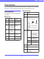
Symbols Used in This Manual
How This Manual is Organized
The following symbols are used in this manual to explain
procedures, restrictions, handling precautions, and
instructions that should be observed for safety.
This manual consists of the following chapters.
■ Hardware
Chapter 1 Before You Start Using the Scanner
Provides an overview of the scanner
Chapter 2 Setup
Describes the operating environment and how to connect
to a PC
Chapter 3 Basic Operation
Describes the basic uses of the scanner
Chapter 4 Other Functions
Describes the User Mode and other functions
Chapter 5 Maintenance
Describes routine cleaning and roller replacement
Chapter 6 Practical Examples
Describes displayed messages and troubleshooting
solutions
Chapter 7 Appendix
Provides a list of specifications and support information
WARNING
Indicates a warning concerning operations that may lead to
death or injury to persons if not performed correctly. To
use the scanner safely, always pay attention to these
warnings.
CAUTION
Indicates a caution concerning operations that may lead to
injury to persons, or damage to property if not performed
correctly. To use the scanner safely, always pay attention
to these cautions.
IMPORTANT
Indicates operational requirements and restrictions. Make
sure that you read these items carefully to operate the
scanner correctly, and avoid damage to the scanner.
■ Software
Chapter 8 ISIS/TWAIN Driver Settings
Describes the settings for the ISIS/TWAIN driver
Chapter 9 Job Registration Tool Settings
Describes the settings for the Job Registration Tool
Chapter 10 Practical Examples
Provides information for reference when making software
settings
Hint
Indicates a clarification of an operation, or contains
additional explanations for a procedure. Reading these
notes is highly recommended.
iv
User Manual
Hardware
Please read this manual before using the scanner.
After you finish reading this manual, keep it in a safe place
for future reference.
Hardware
3. Document Feed and Eject Trays...................... 3-6
Table of Contents
Preparing the Document Feed Tray ..................... 3-6
Adjusting the Document Guides ........................... 3-8
Preparing the Document Eject Tray ................... 3-10
Preface ....................................................................iii
Manuals for the Scanner ......................................... iii
Symbols Used in This Manual ................................. iv
How This Manual is Organized................................iv
4. Document Feeding Methods .......................... 3-11
Selecting the Document Feeding Method .......... 3-11
5. Scanning ........................................................ 3-14
Chapter 1 Before You Start Using the Scanner
About the Job Function....................................... 3-14
CapturePerfect 3.0 ............................................. 3-15
1. Important Safety Instructions............................1-2
Installation Location.............................................. 1-2
Power ................................................................... 1-2
Moving the Scanner.............................................. 1-3
Handling ............................................................... 1-3
Disposal................................................................ 1-5
6. Using Patchcode Sheets (Option).................. 3-20
2. Features ...........................................................1-6
3. Names and Functions of Parts .......................1-10
Paper Jam Handling ........................................... 3-23
Handling a Double Feed..................................... 3-24
About Patchcode Sheets .................................... 3-20
How to Use Patchcode Sheets........................... 3-21
7. Clearing a Paper Jam or Double Feed
Error ............................................................... 3-23
Front View, Feeder Inlet, and Eject Outlet.......... 1-10
Rear View ........................................................... 1-11
Control Panel...................................................... 1-12
Chapter 4 Other Functions
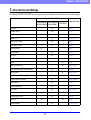
1. Other Functions and Settings........................... 4-2
2. Function Description ........................................ 4-4
3. User Mode........................................................ 4-8
Chapter 2 Setup
1. Setup Procedures.............................................2-2
2. Installation Requirements.................................2-3
3. Software Installation .........................................2-4
User Mode Operating Procedure.......................... 4-8
4. User Mode Functions ..................................... 4-10
Chapter 5 Maintenance
About the Setup Menu.......................................... 2-4
4. Connecting the Scanner to the Computer ........2-6
1. Regular Maintenance ....................................... 5-2
Interface Connector Locations.............................. 2-6
Connecting the Scanner to the Computer ............ 2-6
Cleaning the Scanner ........................................... 5-2
Cleaning the Sensors ........................................... 5-2
Cleaning the Scanning Glass and Rollers ............ 5-3
Power Outlet......................................................... 5-4
5. Turning the Power ON
(Scanner Recognition)......................................2-9
2. Replacing the Transport Rollers....................... 5-5
About the Power Switch ....................................... 2-9
Scanner Recognition ............................................ 2-9
Roller Replacement Cycle .................................... 5-5
Checking and Resetting the Page Counter .......... 5-5
Removing and Reinstalling the Rollers................. 5-7
Chapter 3 Basic Operation
1. Turning the Power ON and OFF ......................3-2
About the Power Switch ....................................... 3-2
2. Documents .......................................................3-3
Acceptable Documents......................................... 3-3
ii
Hardware
3. Imprinter Ink Cartridge Replacement and
Cleaning .........................................................5-13
About the Imprinter ............................................. 5-13
Replacing Ink Cartridges .................................... 5-13
Specifying the Printing Position .......................... 5-15
Cleaning the Imprinter ........................................ 5-16
Imprinter Testing................................................. 5-17
Chapter 6 Practical Examples
1. Messages .........................................................6-2
Status Display....................................................... 6-2
Error Messages .................................................... 6-3
2. Troubleshooting................................................6-5
Trouble Categories ............................................... 6-5
Problem and Solution ........................................... 6-5
3. Uninstalling the Software..................................6-9
Uninstalling the ISIS/TWAIN Driver ...................... 6-9
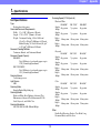
Chapter 7 Appendix
1. Specifications ...................................................7-2
Unit Specifications ................................................ 7-2
Options ................................................................. 7-3
Consumables........................................................ 7-3
External Dimensions............................................. 7-4
2. Option Specifications........................................7-5
Barcode Specifications ......................................... 7-5
Imprinter Specifications ........................................ 7-6
3. Index.................................................................7-7
iii
Chapter 1 Before You Start Using the Scanner
1. Important Safety Instructions ........................... 1-2
Installation Location ..............................................1-2
Power ....................................................................1-2
Moving the Scanner ..............................................1-3
Handling ................................................................1-3
Disposal ................................................................1-5
2. Features........................................................... 1-6
3. Names and Functions of Parts ...................... 1-10
Front View, Feeder Inlet, and Eject Outlet ..........1-10
Rear View............................................................1-11
Control Panel ......................................................1-12
Chapter 1 Before You Start Using the Scanner
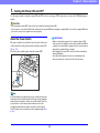
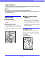
1. Important Safety Instructions
To ensure the safe operation of this scanner, be sure to read the safety warnings and precautions described below.
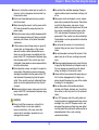
● Avoid locations that are subject to vibration.
● Avoid exposing the scanner to rapid changes in
temperature. If the room in which the scanner is
installed is cold but rapidly heated, water droplets
(condensation) may form inside the scanner. This
may result in a noticeable degradation in scanning
quality.
The following conditions are recommended for
optimal scanning quality:
Room temperature: 10 °C to 32.5 °C (50 °F to
90.5 °F)
Humidity: 20% to 80% RH
● Avoid installing the scanner near equipment that
generates a magnetic field (e.g. speakers,
televisions, or radios).
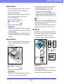
Installation Location
The performance of this scanner is affected by the
environment in which it is installed. Make sure that the
location where the scanner is installed meets the following
environmental requirements.
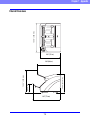
● Provide adequate space around the scanner for
operation, maintenance, and ventilation.
32.20" (818 mm) or more
24.84" (631 mm) or more
3.9" (100 mm) or more
Power
● Connect only to a power outlet of the rated voltage
and power supply frequency (either 120 V, 60 Hz
or 220-240 V, 50/60 Hz, depending on your
region).
● Do not use the scanner with a power supply that is
not rated for the specified voltage. Doing so might
cause fire or electric shock.
● Do not connect other electrical equipment to the
same power outlet to which the scanner is
connected. Also, when using an extension cord,
make sure that the extension cord is rated for the
current requirements of the scanner.
● The power cord may become damaged if it is often
stepped on or if heavy objects are placed on it.
Continued use of a damaged power cord can lead
to an accident, such as a fire or electrical shock.
● Avoid installing the machine in direct sunlight. If
this is unavoidable, use curtains to shade the
scanner.
● Avoid locations where a considerable amount of
dust accumulates.
● Avoid warm or humid locations, such as in the
vicinity of a water faucet, water heater, or
humidifier, and avoid locations where the fumes
from ammonia, paint thinner, or other volatile
chemicals may be present.
1-2
Chapter 1 Before You Start Using the Scanner
● Do not use the power cord while it is coiled.
● Do not pull directly on the power cord. When
disconnecting the power cord, grasp the plug and
remove it from the outlet.
● Keep the area around the power plug clear of
objects so that the power cord can be
disconnected easily in an emergency.
● If you have any questions regarding the power
supply, contact your local authorized Canon dealer
or service representative for further information.
● Make sure to disconnect the interface cable and
power cord when moving the scanner. If the
scanner is carried with these items connected, the
plugs and connectors may be damaged or cause
the scanner to fall and result in personal injury or
damage to the scanner.
Handling
WARNING
Note the following precautions whenever using the
scanner. Failure to do so may result in a fire or
electric shock.
■ Never use alcohol, benzene, paint thinner, aerosol
sprays, or any other highly flammable substance
near the scanner.
■ Do not cut, damage, or modify the power cord. Do
not place heavy objects on the power cord, and do
not pull or excessively bend the power cord.
■ Never connect the power cord when your hands
are wet.
■ Do not connect the scanner to a multiplug power
strip.
■ Do not knot or coil the power cord, as this may
result in a fire or electric shock. When connecting
the power cord, make sure that the power plug is
securely and completely inserted into the power
outlet.
■ To use a reel-type extension cord, unwind all of the
cord from the reel. Long-term operation with the
cord wound on the reel may cause the cord to
overheat and could cause a fire.
■ Do not use power cords other than the power cord
provided with this scanner.
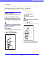
Moving the Scanner
● The scanner weights about 50 lbs (22.5 kg).
To lift or move the scanner, always use two
people, one on each side. Never attempt to lift the
scanner by yourself. You could drop the scanner or
pinch your fingers, resulting in personal injury or
damage to the scanner. Remember to be extra
careful when moving it.
1-3
Chapter 1 Before You Start Using the Scanner
■ Do not block the ventilation openings. Doing so
could case the scanner to overheat, creating a risk
of fire.
■ Never place small metal objects such as staples,
paper clips, or jewelry on the scanner. These items
may fall into the scanner, and cause a fire or
electric shock. Should such objects ever fall inside
the scanner, immediately turn the power switch
OFF, and disconnect the power plug from the
power outlet. Then, contact your local authorized
Canon dealer or service representative to have the
unit serviced.
■ Do not locate the scanner in a humid or dusty
location. Doing so may cause a fire or electric
shock.
■ Do not place objects on top of the scanner. Such
objects may tip or fall over, resulting in personal
injury.
■ When unplugging the power cord, grasp it firmly by
its plug. Do not pull directly on the power cord, as
this may damage or expose the cord’s internal
wiring, resulting in a fire or electric shock.
■ Leave sufficient space around the power plug so
that it can be unplugged easily. If objects are
placed around the power plug, you will be unable
to unplug it in an emergency.
■ Do not allow water or flammable substances
(alcohol, paint thinner, benzene, etc.) to spill into
the scanner, as this may result in a fire or electric
shock.
■ Turn OFF the power switch for safety when not
using the scanner for a long period of time, such as
overnight. Also, turn OFF the power switch, and
disconnect the power cord from the power outlet
for safety when the machine will not be used for an
extended period of time, such as during
consecutive holidays.
■ Never try to take the scanner apart or modify it in
any way, as this is dangerous and may lead to a
fire or electric shock.
■ Do not use flammable aerosol sprays products
near the scanner.
■ When cleaning the scanner, turn the power switch
OFF and disconnect the power plug from the
power supply.
■ Clean the scanner using a slightly dampened cloth
which has been well wrung out. Never use alcohol,
benzene, paint thinner, or any other flammable
substances.
■ If the scanner makes strange noises, or gives off
smoke, heat, or strange odors, or the scanner
does not function or other abnormalities occur
when you use the scanner, immediately turn the
power switch OFF, and disconnect the power plug
from the power outlet. Then, contact your local
authorized Canon dealer or service representative
for further information.
■ Do not drop the scanner, or subject it to impact or
strong shock. Should the scanner ever become
damaged, immediately turn the power switch OFF,
and disconnect the power plug from the power
outlet. Then, contact your local authorized Canon
dealer or service representative to have the unit
serviced.
■ Before moving the scanner, make sure to turn the
power switch OFF, and disconnect the power plug
from the power outlet.
CAUTION
■ Do not install the scanner on a surface that is
unstable or tilted, or in an area subject to
excessive vibrations, as this may cause the
scanner to fall, resulting in personal injury or
damage to the scanner.
1-4
Chapter 1 Before You Start Using the Scanner
■ Do not wear loose clothing or jewelry that may get
caught in the scanner while you are using it. This
may result in personal injury. Be extra careful of
neckties and long hair. If anything becomes caught
in the scanner, immediately disconnect the power
cord to stop the scanner.
■ Be careful when placing paper in the scanner and
when removing jammed paper. It is possible to cut
your hand on the edge of a sheet of paper.
Disposal
● When disposing of this scanner, make sure to
follow all local ordinances and laws or consult with
the retailer who sold you the scanner.
1-5
Chapter 1 Before You Start Using the Scanner
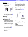
2. Features
The main features of the DR-6050C/7550C/9050C are described below.
● Long Document Mode
Document sheets up to three meters (118.1 inches) long
can be scanned. (See “Long Document Mode Setting”
on p. 3-4.)
● Job Function
Scanning conditions and the saving destination for
image files are registered with the job, so you can scan
using only control panel key operations. (See “About
the Job Function” on p. 3-14.)
● Freely Adjustable Document Guides
The left and right document guides can be adjusted so
that documents can be positioned to scan either the left
or right side. (See “Adjusting the Document Guides” on
p. 3-8.)
● User Mode
The User Mode functions can be employed to set the
scanner for practically any condition. (See “User Mode
Functions” on p. 4-10.)
Scanner Features
● Variety of Scanning Modes
The scanner is equipped with six scanning modes:
Black and White, Error Diffusion, Advanced Text
Enhancement, Advanced Text Enhancement II, 256Color Grayscale, and 24-Bit Color.
* Advanced Text Enhancement can clarify scanned text by
processing background or foreground colors.
● Fast Document Feeding
The scanner can scan up to 90 document sheets per
minute of LTR/A4-size paper in black and white,
grayscale, and color scanning modes. (For the DR9050C)
* Scanning conditions: LTR/A4 portrait, duplex, 200 dpi
● Large Capacity Feeder
Up to 500 plain paper document sheets can be loaded in
the document feed tray. (Maximum of 300 sheets for the
DR-6050C)
● Count-Only Mode
When operating the scanner as a stand-alone device,
this mode counts the number of loaded document
sheets. (See “Count-Only Mode” on p. 4-4.)
● Adjustable Document Feed Tray
The position of the document feed tray can be adjusted
up or down according to the number of document sheets
to be loaded. (See “Preparing the Document Feed Tray”
on p. 3-6.)
1-6
Chapter 1 Before You Start Using the Scanner
● Prescan
At the start of scanning, this function prescans the first
page of a document and pauses so that you can use the
first image to adjust the brightness and contrast before
resuming scanning.
● Verify Scan
While scanning, the count of document pages scanned
is verified against a pre-specified count or the count
obtained from Count-Only Mode. (See “Verify Scan”
on p. 4-4.)
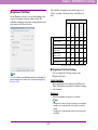
● Text Orientation Detection
The text orientation on each page is detected, and the
scanned image is rotated in 90-degree increments as
necessary for normalization.
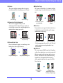
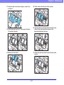
Detection Functions
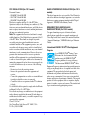
● Auto Image Type Detection
The scanner automatically detects whether documents
are in black and white or color.
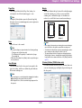
● Auto Paper Size Detection
The document page size is detected before scanning.
Fixed-Size Scanning
Auto-Size Detection
Scanning
● Skew Detection
The scanner stops feeding when a skewed document is
detected as it touches the edge of the feeder inlet. (See
“Skew Detection” on p. 4-6.)
● Staple Detection
The scanner stops feeding when it detects the presence
of stapled documents. (See “Staple Detection” on
p. 4-6.)
● Ultrasonic Double-Feed Detection
The scanner stops feeding when the ultrasonic sensor
detects that two or more document pages are feeding at
the same time. (See “Double-Feed Detection” on
p. 4-5.)
Feeding Direction
The text orientation is
detected and the image is
rotated
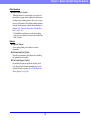
Image Processing
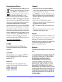
● Prevent Bleed Through/Remove Background
Prevents the background or original image on the
reverse side of thin originals from appearing in scanned
images.
● Image Rotation
The scanner can rotate scanned images in 90°
increments, or detect the text orientation and rotate the
image in 90° increments to correct its orientation.
* A non-detection zone can be specified to avoid doublefeed detection in areas such as those containing adhesive
labels.
● Double-Feed Detection by Document Length
The scanner stops feeding when a double feed is
detected by comparing document lengths. (See
“Double-Feed Detection” on p. 4-5.)
* Using the length of the first document page as a reference,
the scanner detects a double feed when a page of a
different length is fed.
1-7
Chapter 1 Before You Start Using the Scanner
● Deskew
The scanner straightens an image when it recognizes
from the image that the document page was fed askew.
Skewed Image
● Skip Blank Page
The scanner scans both sides of a document and skips
saving the image of any side it determines to be a blank
page.
Deskewed Image
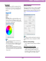
● Dropout and Color Enhancement
The scanner is equipped with drop-out and
enhancement functions that enable you to specify one
color (red, blue, or green) to be omitted (dropped out) or
enhanced when scanning, respectively.
Color Document
Two-Sided Documents
with a Blank Side
● Folio Scan
Documents that are too large to fit in the feeder inlet can
be folded and scanned on both sides, and the images
combined into a single image.
Image with Red Drop-Out
set (red filtered)
Front and Back Images
● Remove Binder Holes
Erases the shadows that appear on scanned images form
binding holes on the original document.
Image with Binding Holes
Images with Blank Page
Skipped
Reconstructed Image
* Folio Scan supports up to A1-size (23.4" × 33.1" (594 × 841
mm)) documents when used together with the Long
Document Mode.
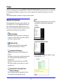
● MultiStream
The scanner supports MultiStream, which, depending
on the software application, can create two images with
different scanning conditions from a single scan pass.
However, this function is only available when using
CapturePerfect 3.0 (supplied with the scanner) or
another application program that supports the MultiStream function.
Image without Binding Holes
Document to be
Scanned
1-8
(150 dpi, Color)
(300 dpi, Black & White)
Two Types of Output Image
Chapter 1 Before You Start Using the Scanner
Other Functions
● Rapid Recovery System
When this function is activated and a sensor detects a
misfeed due to a paper jam or double feed, which causes
feeding to stop, scanning pauses to allow you to correct
the cause of the misfeed, after which scanning continues
from the document page on which the abnormality was
detected. (See “Clearing a Paper Jam or Double Feed
Error” on p. 3-23.)
* The Rapid Recovery System is effective when feeding
stops as a result of detection of a Paper Jam, Double Feed,
Skew, or Staple.
Options
● Imprinter (Option)
As an option, printing can be made on scanned
documents.
● Barcode Detection (Option)
Barcodes on documents can be detected by installing
the optional barcode module.
● Patchcode Support (Option)
By installing the optional patchcode decoder, patch
code sheets inserted between document pages can be
detected for batch separation. (See “Using Patchcode
Sheets (Option)” on p. 3-20.)
1-9
Chapter 1 Before You Start Using the Scanner
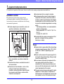
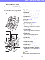
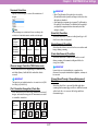
3. Names and Functions of Parts
The names and functions of the DR-6050C/7550C/9050C parts are shown below.
a Upper Unit
Open when cleaning the rollers or paper jams. (See p. 3-23.)
b Imprinter Cover
Open when replacing the ink cartridge in the optional
imprinter or when cleaning the imprinter. (See p. 5-13.)
c Document Eject Tray
Scanned documents are output here. (See p. 3-10.)
d Control Panel (See p. 1-12.)
e Power Switch
Turns the scanner ON and OFF. (See p. 3-2.)
f Document Eject Tray Extension
Open the Document Eject Tray Extension when
documents look like they are going to fall off of the eject
tray. (See p. 3-10.)
g Eject Paper Stoppers
Adjust to fit the length of documents, to avoid document
spillage. (See p. 3-10.)
h Document Guides
Adjust to fit the width of documents, so that ejected
documents stack neatly. (See p. 3-10.)
i Document Guides
Adjust to fit the width of documents. (See p. 3-8 and
p. 3-9.)
+ Document Guide Lock Lever
Locks the Document Guides. (See p. 3-9.)
, Document Feed Tray
Load documents to be scanned here. (See p. 3-6.)
- Document Feeder Tray Extension / Extension Wire
Extend as needed to fit the length of the documents. (See
p. 3-7.)
Front View, Feeder Inlet, and Eject Outlet
CAUTION
Do not open the imprinter cover if the optional imprinter is not installed.
1-10
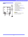
Chapter 1 Before You Start Using the Scanner
a Ventilation Holes (Exhaust Fan)
Exhausts heat from inside the scanner.
b Power Connector
Connect the supplied power cord here. (See p. 2-7.)
c USB Connector (Type B)
Connect the supplied USB cable here. (See p. 2-6.)
d SCSI Connector (50-pin half-pitch D-sub receptacle)
Connect the SCSI cable here. (See p. 2-7.)
e DIP Switches (SCSI ID)
Selects the scanner’s SCSI ID. (See p. 2-8.)
Rear View
CAUTION
Do not block the ventilation holes. Doing so could cause the
scanner to overheat, creating a fire hazard.
1-11
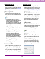
Chapter 1 Before You Start Using the Scanner
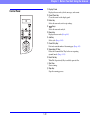
a Display Panel
Displays the user mode, job info, messages, and counter.
b Count Clear Key
Clears the counter on the display panel.
c Enter Key
Selects the user mode, and accepts settings.
d
Keys
Selects the user mode and job.
e Menu Key
Displays the user mode. (See p. 4-8.)
f Job Key
Selects jobs. (See p. 3-14.)
g Count Only Key
Feeds and counts the number of document pages. (See p. 4-4.)
h Separation Off Key
Raises the Document Feed Tray for the non-separating
(manual) mode. (See p. 3-11.)
i New File Key
When File Separation by Key is enabled, separates files.
+ Start Key
Starts scanning.
, Stop Key
Stops the scanning process.
Control Panel
1-12
Chapter 2 Setup
1. Setup Procedures ............................................ 2-2
2. Installation Requirements ................................ 2-3
3. Software Installation ........................................ 2-4
About the Setup Menu ..........................................2-4
4. Connecting the Scanner to the Computer ....... 2-6
Interface Connector Locations ..............................2-6
Connecting the Scanner to the Computer.............2-6
5. Turning the Power ON
(Scanner Recognition) ..................................... 2-9
About the Power Switch ........................................2-9
Scanner Recognition.............................................2-9
Chapter 2 Setup
1. Setup Procedures
Perform the following setup procedures to prepare the scanner for use.
Step 1: Confirm the installation requirements. (See p. 2-3)
Step 2: Install the Software. (See p. 2-4)
Step 3: Connect the scanner to the computer. (See p. 2-6)
Step 4: Turn the power ON (Scanner recognition). (See p. 2-9)
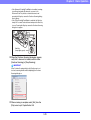
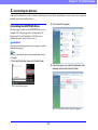
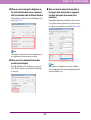
• Windows XP
IMPORTANT
• Make sure that you install the software before connecting the
scanner to the computer.
• If you connect the scanner to the computer before installing
the software, a wizard screen such as the one shown below
will appear when you turn the scanner ON. In this case, click
[Cancel] to close the wizard screen, and then turn the scanner
OFF.
• Windows 2000
• Windows Vista
2-2
Chapter 2 Setup
2. Installation Requirements
To use the scanner, your computer must satisfy the following system requirements.
■ Operating System:
IMPORTANT
• Microsoft Windows 2000 Professional SP4 or later
• Microsoft Windows XP Professional SP3 or later
• Microsoft Windows XP Home Edition SP3 or later
• Microsoft Windows XP Professional x64 Edition SP2 or
later
• Microsoft Windows Vista Home Basic, Home Premium,
Business, Ultimate or Enterprise SP1 or later
• If you do not know the requirements for your computer system,
contact the store where you purchased the computer or the
manufacturer of the computer for more information.
• Do not connect both a USB interface and a SCSI card at the
same time.
• Note the following points when using the USB interface that
was provided with your computer.
– The USB connection should be a Hi-Speed USB 2.0
interface.
– Scanning speeds are lower if your computer’s standard
USB interface is USB Full-Speed (equal to USB 1.1).
– Use the most recently available USB 2.0 driver provided by
Microsoft. Contact your local authorized Canon dealer for
more detailed information.
– Not all USB interfaces provided as standard with personal
computers are guaranteed. Contact your local authorized
Canon dealer for more detailed information.
– Use the USB cable that was originally bundled with the
scanner or a Hi-Speed USB 2.0 compatible cable.
• Note the following when using a SCSI card.
– Make sure to follow the procedure in the manual for the
SCSI card and the computer that you are using when
installing a SCSI card in your computer.
– The overall length of the SCSI cable you can use is
determined by the SCSI standards. Refer to the manual for
the SCSI card you are using for more information.
• If the CPU, memory, interface card, and other specifications
do not satisfy the installation requirements, the scanning
speed may be greatly reduced and transmission may take a
longer time.
• Even if the computer satisfies the recommended
specifications, the scanning speed may vary, depending on
the scan settings.
• The ISIS/TWAIN Drivers provided with the scanner do not
necessarily operate on all ISIS- or TWAIN-compatible
applications. For details, contact your application software
retailer.
Hint
Microsoft Windows Vista has 32- and 64-bit versions.
■ Computer Specifications:
• CPU: Celeron, 1.6GHz or faster
• Memory: 512MB or more
• Hard disk: 1 GB or more available space
• CD-ROM drive
• Interface: One standard Hi-Speed USB 2.0 port on the
PC, or a SCSI expansion card
• Monitor: Resolution of 1024 × 768 (XGA) or better
recommended
■ Recommended SCSI Cards:
SCSI cards made by Adaptec (for PCI bus)
• AVA-2915LP
• AVA-2930LP
SCSI card made by RATOC Systems (for Card bus)
• REX-CB31
■ An ISIS-compatible application or a TWAINcompatible application that is compatible with
the above operating systems.
2-3
Chapter 2 Setup
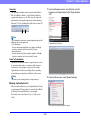
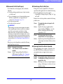
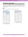
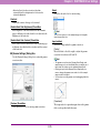
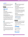
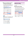
3. Software Installation
This section describes how to install the software.
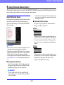
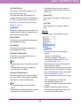
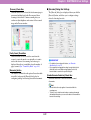
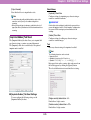
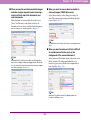
■ The Typical Installation Screen
About the Setup Menu
This screen appears when you click “Typical Installation”
on the Menu screen. Click [Install] to install all of the
listed software.
When you insert the included Setup disc into the computer’s
CD drive, the menu shown below should appear. If the menu
does not appear, use Explorer to access the CD drive and
execute the file “SETUP.EXE”.
Hint
See the Easy Start Guide for instructions on using the typical
installation procedure.
IMPORTANT
• As always when installing software, log in using an account with
Administrator privileges.
• When using Windows Vista, the “User Account Control” dialog
box may appear. In this case, enter your login user password for
Administrator privileges, and click [OK].
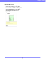
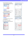
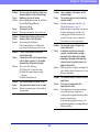
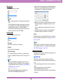
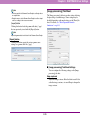
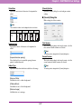
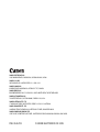
■ The Custom Installation Screen
This screen appears when you click “Custom Installation”
on the Menu screen. Select the check boxes next to the
software that you want to install.
Click [Install] to install the selected software.
2-4
Chapter 2 Setup
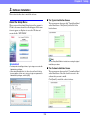
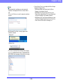
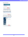
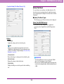
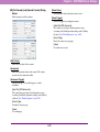
■ The Read Manual Screen
From this screen you can select one of the supplied
electronic manuals to read: the Easy Start Guide (a printed
copy is also supplied), the Reference Guide, the User
Manual (this manual), or the CapturePerfect 3.0
Operation Guide.
2-5
Chapter 2 Setup
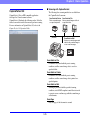
4. Connecting the Scanner to the Computer
There are two methods for connecting the scanner to a computer: a USB connection to a standard USB port built in to the computer,
or SCSI connection to a SCSI card installed in an expansion slot of the computer. Select the method that is best suited to your
computer environment.
Interface Connector Locations
Connecting the Scanner to the Computer
The USB port and SCSI connector are located on the scanner
as shown below.
To connect to the computer, follow the procedure for the
intended connection method.
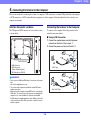
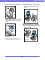
■ Using a USB Connection
1. Connect the supplied power cord into the power
connector on the back of the scanner. a
2. Connect the power cord into an AC outlet. b
Power Connector
a USB Connector
b SCSI Connector
c
120 V Type
(D-sub, 50-pin half-pitch)
DIP Switches for SCSI ID
IMPORTANT
• Do not connect a USB and SCSI cable to the scanner at the same
time.
• Use only the supplied power cord.
• The scanner and computer should both be turned OFF when
making connections.
• Make sure that the computer is turned OFF before connecting the
SCSI cable. The scanner may not be properly recognized by the
computer if it is connected while the computer is turned ON.
• A SCSI cable is not supplied with the scanner. Obtain a cable with
connectors that match the SCSI connectors on both the scanner
and the computer.
220 - 240 V Type
2-6
Chapter 2 Setup
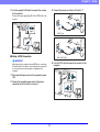
3. Connect the power cord into an AC outlet. b
3. Use the supplied USB cable to connect the scanner
to the computer.
Connect the square plug (Type B) of the USB cable to the
scanner.
Type B
120 V Type
Type A
■ Using a SCSI Connection
220 - 240 V Type
IMPORTANT
4. Use the SCSI cable to connect the scanner to the
Make sure that the computer is turned OFF before connecting
the SCSI cable. If the cable is connected while the computer is
on, the scanner may not be properly recognized by the
computer.
computer.
1. Shut down Windows and turn the computer’s power
OFF.
2. Connect the supplied power cord into the power
connector on the back of the scanner. a
2-7
Chapter 2 Setup
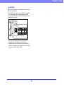
IMPORTANT
Observe the following when connecting the scanner with other
devices in a “daisy chain”.
• The SCSI ID of the scanner is set to “SCSI ID = 2” by default.
When using a daisy-chain configuration with other SCSI
devices, set the DIP switches so that SCSI ID numbers are not
duplicated in the system.
DIP Switches
Default Position (SCSI ID=2)
• The scanner incorporates a SCSI terminator which is
permanently set to ON. When using a daisy-chain
configuration with other SCSI devices, make sure that the
scanner is connected as the last device in the chain. Set the
terminators of all other devices to OFF.
2-8
Chapter 2 Setup
5. Turning the Power ON (Scanner Recognition)
When you turn ON the computer and the scanner, the Windows Plug and Play function recognizes the scanner and automatically
installs the required device driver.
About the Power Switch
Scanner Recognition
The power switch is located at the lower left side of the front
of the scanner. Press the power switch to turn the scanner ON.
(See p. 3-6.)
Press the power switch again to turn the scanner OFF.
The scanner will be recognized the first time it is connected to
the computer.
1. Make sure that the scanner and computer are
connected properly.
2. Turn ON the scanner.
3. Turn ON the computer.
4. Log onto Windows as an Administrator.
5. Windows automatically recognizes the scanner and
performs the device driver installation.
• Windows 2000
Power Switch
• Windows XP
IMPORTANT
• When connecting the scanner to the computer using a SCSI
cable, be sure to turn ON the scanner first, and then turn ON the
computer. If you turn ON the computer first, the scanner may not
be properly recognized by the computer.
• After turning the scanner OFF, wait at least 10 seconds before
turning it ON again.
• If you will not be using the scanner for an extended period,
disconnect the power cord from the AC outlet for safety.
• Windows Vista
2-9
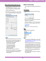
Chapter 2 Setup
• From the Control Panel, you can display the Device Manager
using the following procedure:
– With Windows 2000, open [System] and click [Device
Manager] on the Hardware tab sheet.
– With Windows XP, first switch the Control Panel to the
Classic View to display [System]. Then open [System] and
click [Device Manager] on the Hardware tab sheet.
– With Windows Vista, open [System and Maintenance] and
click [Device Manager]. Or, switch the Control Panel to the
Classic View and click the [Device Manager] icon.
Hint
• With Windows Vista, installation proceeds automatically
regardless of the displayed “Click here for status” balloon
help.
You can click “Click here for status” to display the installation
progress.
• With Windows XP and Vista, a message appears when
installation is finished.
• Windows XP
• Windows Vista
• The scanner is installed in Device Manager under [Imaging
devices] as [CANON DR-XXXX USB] or [CANON DR-XXXX
SCSI]. (XXXX varies depending on the model you are using)
2-10
Chapter 3 Basic Operation
1. Turning the Power ON and OFF...................... 3-2
About the Power Switch ........................................3-2
2. Documents....................................................... 3-3
Acceptable Documents .........................................3-3
3. Document Feed and Eject Trays ..................... 3-6
Preparing the Document Feed Tray......................3-6
Adjusting the Document Guides............................3-8
Preparing the Document Eject Tray ....................3-10
4. Document Feeding Methods.......................... 3-11
Selecting the Document Feeding Method ...........3-11
5. Scanning........................................................ 3-14
About the Job Function .......................................3-14
CapturePerfect 3.0 ..............................................3-15
6. Using Patchcode Sheets (Option) ................. 3-20
About Patchcode Sheets.....................................3-20
How to Use Patchcode Sheets ...........................3-21
7. Clearing a Paper Jam or Double Feed
Error............................................................... 3-23
Paper Jam Handling............................................3-23
Handling a Double Feed .....................................3-24
Chapter 3 Basic Operation
1. Turning the Power ON and OFF
Use the power switch to turn the scanner ON and OFF, or if you are using a USB connection, you can set the USB-linked power
switch.
CAUTION
• After turning the scanner OFF, wait at least ten seconds before turning it back ON.
• If the scanner is connected via SCSI cable, always turn the scanner ON before turning the computer ON. If you turn the computer ON before
the scanner, it may not recognize the scanner properly.
IMPORTANT
About the Power Switch
• When connecting the scanner to the computer using a SCSI
cable, be sure to turn ON the scanner first, and then turn ON the
computer. If you turn ON the computer first, the scanner may not
be properly recognized by the computer.
• After turning the scanner OFF, wait at least 10 seconds before
turning it ON again.
• If you will not be using the scanner for an extended period,
disconnect the power cord from the AC outlet for safety.
The power switch is located at the lower left side of the front
of the scanner. Press the power switch to turn the scanner ON.
(See p. 3-6.)
Press the power switch again to turn the scanner OFF.
Power Switch
Hint
In the User Mode, if the tray position is set to a height other than the
lowest position, then the Document Feed Tray moves up and down
when the power is turned on. In this case, the Document Feed Tray
is lowered once to the lowest position and then moves to the
configured height. When the power is turned off, the Document
Feed Tray does not move and stays at the configured height. (See
p. 3-6.)
3-2
Chapter 3 Basic Operation
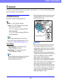
2. Documents
The scanner can scan documents ranging in size from business cards and checks to 11" × 17"/A3 size. The size and type of paper
that can be fed depends on the feeding method.
• Manual feeding requires feeding one document at a time while
the [Separation Off] key on the control panel is lit and the
Document Feed Tray is raised.
Acceptable Documents
The scanner can feed the following document sizes.
Size
Width: 2" to 12.01" (50.8 mm to 305 mm)
Length: 2.76" to 17.01" (70 mm to 432 mm) (without
using the Long Document Mode)
2.76" to 39.37" (70 mm to 1m) (using [ON1] in the
Long Document Mode)
2.76" to 118.11" (70 mm to 3m) (using [ON2] in the
Long Document Mode)
Separation Off Key
Hint
When the Long Document Mode is selected, Paper Size
Detection can be used for scanning documents up to 118.11"
(3 m) long. (See “Long Document Mode Setting” on p. 3-4.)
IMPORTANT
Paper Thickness
Continuous Feeding: 14 to 56 lb bond (52 g/m2 to
209 g/m2) (0.06 mm to 0.25 mm)
Manual Feeding: 11 lb to 64 lb bond (42 g/m2 to
255 g/m2) (0.05 mm to 0.30 mm)
A document must meet the following criteria to be scannable:
• When scanning a multipage document, pages must be
grouped together so that they have the same size, thickness,
and weight. Scanning different types of paper at one time can
cause the scanner to jam.
• Always make sure that the ink on a document is dry before
scanning it. Scanning documents with the ink still wet may soil
the rollers or scanning glass, cause lines or smudges to
appear on images, or dirty other documents.
• Always clean the rollers or scanning glass after scanning a
document written in pencil. Scanning documents with pencil
written on them may soil the rollers or scanning glass, cause
stripes to appear in images, or dirty other documents.
• When scanning a two-sided document that is printed on thin
paper, the image on the opposite side of each page may show
through. Adjust the scanning brightness from the application
program, or enable the [Prevent Bleed Through/Remove
Background] setting before scanning.
Hint
• Continuous feeding feeds document pages one after another
by the feed and retard rollers after placing a batch of
documents in the Document Feed Tray.
3-3
Chapter 3 Basic Operation
Small Size Limitation Mark:
When placing documents that are smaller than LTR/A4 size.
Large Size Limitation Mark:
When placing documents that are larger than LTR/A4 size.
• Note that scanning the following types of documents can
cause a paper jam or malfunction. To scan such a document,
make a photocopy of the document and then scan the
photocopy.
Wrinkled or creased
documents
Carbon paper
Curled documents
Coated paper
Torn documents
Extremely thin,
translucent paper
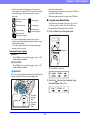
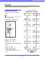
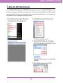
■ Long Document Mode Setting
Using the Long Document mode, pages up to 118.11"
(3 m) long can be scanned. You can set the Long
Document Mode setting from the User Mode.
1. Press the Menu key on the control panel.
Documents with
paper clips or staples
• To scan bound multi-page documents such as invoice
booklets, place the bound edge against the feeder inlet and
scan by manual feeding.
• To use the Long Document Mode, feed document pages
manually, one after another.
Menu Key
Document Feeder Capacity
DR-6050C:
Up to 300 sheets of good quality paper or up to 1.10"
(28 mm) high (maximum)
DR-7550C/9050C:
Up to 500 sheets of good quality paper or up to 1.89"
(48 mm) high (maximum)
The User Mode is activated.
IMPORTANT
Do not exceed the load limitation mark when placing documents
in the Document Feed Tray. It may cause paper jams.
2. Press the [
] key four times to display Long
Document Mode. (See p. 4-8.)
Small Size
Limitation
Mark
Large Size
Limitation
Mark
3-4
Chapter 3 Basic Operation
3. Confirm your settings.
• When scanning with the Long Document Mode set to [ON2], if
the scan is performed at 400/600 dpi or the scan is performed
with the scanning mode set to color and the scanning side set
to [Duplex], the image may be lost. If this occurs, scan by
reducing the resolution, using black and white, or setting the
scanning side to [Simplex].
• When scanning using Long Document Mode, [High-Quality
Moire Reduction], [Deskew], or document orientation of [90
degrees] or [270 degrees] cannot be used.
• If a sheet is loaded at a skewed angle when scanning long
documents, it may be damaged by contacting both sides of the
transport path. So be careful to avoid loading documents at
skewed angles.
• Paper jam detection may react slowly when scanning long
documents, which could result in jammed documents being
damaged. Be especially careful to avoid paper jams.
• To feed each document page manually when scanning long
documents, press the [Separation Off] key on the control
panel.
[ON2]: When the [Auto Detection] or [Scanner’s
Maximum] page size setting is selected, document page
lengths up to 118.11" (3 m) can be detected.
[ON1]: When the [Auto Detection] or [Scanner’s
Maximum] page size setting is selected, document page
lengths up to 39.37" (1 m) can be detected.
[OFF]: When the [Auto Detection] page size setting is
selected, document page lengths up to 17.01" (432 mm)
can be detected.
4. Press [Enter].
Enter Key
Separation
Off Key
The current setting is indicated by blinking square brackets
[ ].
5. Press the [
] or [ ] key to select [ON] or [OFF], and
press [Enter] to accept the selection.
6. Press the Stop key to exit the User Mode.
IMPORTANT
• Processing may be slowed when scanning in the Long
Document Mode.
• When scanning with the Long Document Mode set to [ON1], if
the scan is performed with the scanning mode set to color and
the image quality set to [Image quality priority], the image may
be lost. If this occurs, scan by using black and white or
reducing the image quality.
3-5
Chapter 3 Basic Operation
3. Document Feed and Eject Trays
Before scanning, prepare the Document Feed and Eject Trays for the desired paper size.
1. Press the Menu key on the control panel.
Preparing the Document Feed Tray
■ Document Feed Tray
The height of the Document Feed Tray can be adjusted
according to the number of document pages to be loaded
(the default setting is the lowest position).
Menu Key
The User Mode is activated.
Tray Position Setting
The height of the Document Feed Tray is set by the Tray
Position in the User Mode setting, which minimizes the
time required to start feeding by specifying in advance the
proper position for the documents to be loaded.
2. Press the [
] key five times to display Tray Position.
(See p. 4-8.)
3. Confirm your settings.
For the DR-6050C
[0]: To load up to 300 sheets
[1]: To load up to 100 sheets
For the DR-7550C/9050C
[0]: To load up to 500 sheets
[1]: To load up to 300 sheets
[2]: To load up to 100 sheets
3-6
Chapter 3 Basic Operation
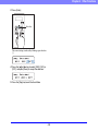
■ Document Guides
4. Press [Enter].
Slide the document guides to fit the width of your
document.
Enter Key
Hint
The positions of the left and right document guides can also be
locked independently for off-center loading. For details, see
“Adjusting the Document Guides” (p. 3-8).
The current setting is indicated by blinking square brackets
[ ].
5. Press the [
] or [
] key to select [0], [1] or [2].
■ Document Feeder Tray Extension / Extension
Wire
6. Press [Enter] to accept the selection.
The Document Feed Tray moves to the selected height.
Pull out the tray extension as needed for the length of your
document.
7. Press the Stop key to exit the User Mode.
3-7
Chapter 3 Basic Operation
■ Loading Documents at the Left Side
Gently open the extension wire.
This example shows the procedure for loading documents
at the left side of the feeder.
1. Spread the document guides all the way to the left
and right.
Hint
Use the extension wire if the document extends beyond the
edge of the document tray.
2. Load your documents against the left feed guide.
Adjusting the Document Guides
The document guides normally extend at equal distances from
the left and right of the center of feeding so that your
documents are centered in the feed inlet.
However, each document guide has its own lock lever, so you
can load documents to the left or right of center by locking the
document guides at the appropriate positions.
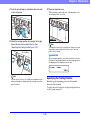
3. Lock the left document guide (a) by pulling out the
lock lever, then slide the right document guide to the
right edge of your documents (b).
3-8
Chapter 3 Basic Operation
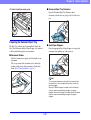
■ Resetting the Document Guides
4. Lock the right document guide (a), and unlock the
left document guide (b).
To reset the guides so that they are equidistant from the
center, perform the following procedure to spread the
guides to the left and right as far as they will go.
1. Confirm that the right document guide is locked (a),
and slide the left guide all the way to the left (b).
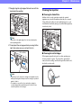
5. Slide the left document guide to the left edge of your
documents.
2. Lock the left document guide (a), and unlock the
right document guide (b).
3. Slide the right document guide all the way to the right.
3-9
Chapter 3 Basic Operation
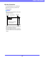
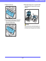
■ Document Eject Tray Extension
4. Unlock the left document guide.
Open the Document Eject Tray Extension when
documents look like they are going to fall off of the eject
tray.
Preparing the Document Eject Tray
■ Eject Paper Stoppers
The Eject Tray includes two Document Eject Guides, the
Eject Tray Extension and Eject Paper Stopper, to be adjusted
to fit the width and length of your documents.
Raise the appropriate Eject Paper Stoppers to stop ejected
documents from spilling out of the eject tray.
■ Document Guides
Slide the document eject guides to fit the width of your
documents.
The eject position of the document can be checked by
feeding a single sheet of the document in Count-Only
Mode. (See “Count-Only Mode” on p. 4-4.)
Hint
The eject paper stoppers are attached to the document eject
tray extension, so you can adjust their positions to suit your
document length.
When an LTR/A4-size paper is loaded, close the document
eject tray extension and stand up the upper eject paper
stoppers. When an A3-size paper is loaded, open the document
eject tray extension and stand up the upper eject paper
stoppers.
3-10
Chapter 3 Basic Operation
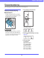
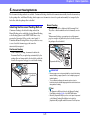
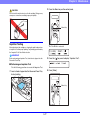
4. Document Feeding Methods
Two document feeding methods are available: Continuous Feeding, which feeds documents automatically from the document tray
by the pickup roller; and Manual Feeding, which requires one document at a time to be positioned manually for transport by the
feed roller, while the pickup roller is disabled.
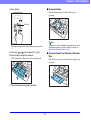
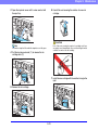
Manual Feeding
The Separation Off key lights and the Document Feed
Tray rises so that documents can be fed manually one at a
time.
When manual feeding, you must insert each document
page far enough to be pulled in by the feed roller (because
the pickup roller is disabled).
Selecting the Document Feeding Method
Continuous Feeding is the default feeding method, but
Manual Feeding can be enabled by selecting Manual Feeding
as the Feeding Option for the ISIS/TWAIN driver, or by
pressing the Separation Off key on the control panel. A
Continuous Manual Feeding Mode is also provided as a way
to scan a batch of document pages that cannot be
automatically transported.
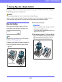
Continuous Feeding
With Continuous Feeding, documents loaded in the
Document Feed Tray are picked up automatically by the
pickup roller and transported by the feed roller, while the
retard roller separates each page to avoid double feeding.
Separation Off Key
IMPORTANT
Pickup Roller
• Because pages are not separated by the retard roller during
manual feeding, a paper jam will occur if multiple pages are
loaded together.
• To scan bound multi-page documents such as invoice
booklets, place the bound edge against the feed inlet and scan
using manual feeding.
Feed Roller
Retard Roller
Hint
• The [Separation Off] key is linked to the [Manual Feeding]
Feed Option setting (p. 8-20) of the ISIS/TWAIN driver.
• When the [Separation Off] key on the control panel is pressed
or the [Manual Feeding] Feed Option is selected, the
[Separation Off] key lights and the Document Feed Tray rises.
3-11
Chapter 3 Basic Operation
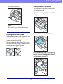
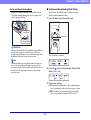
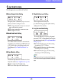
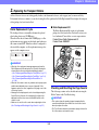
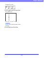
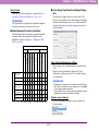
■ Continuous Manual Feeding Mode Setting
Continuous Manual Feeding Mode
Enable the Continuous Manual Feeding Mode from the
User Mode when document pages do not separate well
using Continuous Feeding.
Select Manual Feed Mode in the User Mode settings to
enable continuous manual feeding.
1. Press the Menu key on the control panel.
Feed Roller
Menu Key
Retard Roller
IMPORTANT
When the Continuous Manual Feeding Mode is set to ON from
the User Mode, make sure to disable it (set to OFF) when
finished scanning. Otherwise, normal continuous feeding will be
disabled the next time someone uses the scanner.
The User Mode is activated.
Hint
For Manual Feeding, you must feed document one page at a
time. For Continuous Manual Feeding, you must place the
documents on the Document Feed Tray and insert them into the
Document Feed Tray opening one page at a time, making
operation easier.
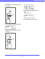
2. Press the [
] key five times to display “Manual Feed
Mode”. (See p. 4-8.)
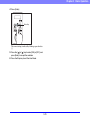
3. Confirm your settings.
[ON]: Disables the pickup roller so that loaded documents
have to be hand fed to the feed roller one page at a time.
[OFF]: Documents are fed continuously by the pickup
roller, except when the Separation Off key is lit.
3-12
Chapter 3 Basic Operation
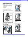
4. Press [Enter].
Enter Key
The current setting is indicated by blinking square brackets
[ ].
5. Press the [
] or [ ] key to select [ON] or [OFF], and
press [Enter] to accept the selection.
6. Press the Stop key to exit the User Mode.
3-13
Chapter 3 Basic Operation
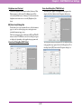
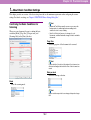
5. Scanning
Scanning operations can be controlled by a scanning application program such as the CapturePerfect 3.0 software included with the
scanner, or directly from the control panel of the DR-6050C/7550C/9050C, using the Job Function.
This section describes the Job Function and provides an overview of CapturePerfect 3.0.
Registered jobs are displayed.
About the Job Function
The Job Function enables you to use the Job Registration Tool
to register different jobs which can then be selected for
scanning by pressing the [Job] key on the control panel.
Job registration stores scanning condition settings, image file
format selection, save destination, and image data processing
settings for each job to be used with the Job Function.
Hint
If no job is displayed, you must register a job using the Job
Registration Tool.
2. Press the [
Hint
] or [
] key to select a job.
3. Execute the displayed job by pressing the Start key.
The Job Registration Tool is a TWAIN-compliant application that is
installed along with the ISIS/TWAIN driver. See Chapter 9 “Job
Registration Tool Settings” for details.
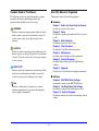
■ Executing Jobs
Use the following procedure to execute jobs that have been
registered by the Job Registration Tool.
1. Press the Job key on the control panel.
Start Key
Job Key
4. Open the folder specified during job registration to
confirm that the image files have been created.
3-14
Chapter 3 Basic Operation
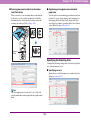
■ Scanning with CapturePerfect
CapturePerfect 3.0
The following three scanning methods are available from
the CapturePerfect Scan menu.
CapturePerfect 3.0 is an ISIS-compatible application
developed for Canon document scanners.
CapturePerfect 3.0 includes the following modes. Select the
desired scan mode from the Scan menu to perform scanning.
For more information on CapturePerfect 3.0, refer to the
CapturePerfect 3.0 Operation Guide.
Scan Batch to Printer
Prints scanned images
on a specified printer
(Network)
Scan Batch to File
Saves scanned images as files in
a specified folder
Scan Batch to Mail
Starts your e-mail program and
attaches the scanned image to
a new e-mail message
Scan Batch to File
Documents are scanned with the preset scanning
conditions, and the scanned image data is saved to a
specified folder.
Scan Batch to Printer
Documents are scanned with the preset scanning
conditions, and the scanned image data is printed on a
specified printer.
Scan Batch to Mail
Scanning is performed with the specified scanning
conditions, and a MAPI-compliant e-mail client is started
to generate a new e-mail message with the scanned images
as attachments.
Scan Page
Only one page of the document is scanned.
3-15
Chapter 3 Basic Operation
1. From the Windows task bar, click [Start] ➔ click [All
Scan Job
The scanning conditions and scan mode (Scan Batch to
File, Scan Batch to Printer, or Scan Batch to Mail) are
registered in advance as a job. The scan job can then be
performed by selecting the registered job from the dropdown list (a) or by clicking (Scan Job) on the toolbar (b).
b
Programs] ➔ [CapturePerfect 3.0] ➔ [CapturePerfect
3.0].
a
Hint
The following two scan jobs are already registered and up to 99
additional jobs can be registered.
• Color Document
Scan the document using 24-bit color, simplex, at 300 dpi
resolution, and save the file in the folder [Pictures].
• Binary Document
Scan the document in black-and-white, simplex, at 200 dpi
resolution, and save the file in the folder [Pictures].
CapturePerfect 3.0 starts.
Scan To Presentation
This mode is convenient when a compact scanner is used
in an environment such as a conference hall, where it is
connected to a large display or projector. By setting
CapturePerfect for full-screen display before scanning,
scanned images are displayed at full size on the screen.
Hint
2. From the [Scan] menu, select [Select Scanner].
This function is not usually practical for large scanners.
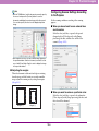
■ Using CapturePerfect 3.0
This section describes how to start CapturePerfect 3.0 and
scan documents. The procedure for using the Scan Batch
to File function is described here as an example.
For details, refer to the CapturePerfect 3.0 Operation
Guide.
The [Select Scanner] dialog box opens.
3-16
Chapter 3 Basic Operation
3. Select [CANON DR-XXXX] and click [Settings].
The [Scan Batch to File Setting] dialog box opens.
(XXXX varies depending on the model you are using)
IMPORTANT
If [CANON DR-XXXX] is not displayed in the list of scanners,
you must re-install the ISIS/TWAIN driver.
4. Select the default page size and click [OK].
7. Click the [Scanner Setting] button.
IMPORTANT
If you select [Default] in the ISIS driver properties dialog box,
that setting is applied here.
5. Click [OK] to finish scanner selection.
6. From the [Scan] menu, select [Scan Batch to File].
3-17
Chapter 3 Basic Operation
The Properties dialog box for the ISIS driver opens.
IMPORTANT
You must load your documents as described below, depending
on the specified Feed Option setting.
• If the [Standard Feeding] Feed Option is enabled, load your
documents before scanning. When all of the documents have
been scanned, the Continue Scanning dialog box appears.
• If the [Manual Feeding] Feed Option is enabled, the
Separation Off key is lit and the Document Feed Tray is
raised. You must insert one page at a time to be scanned, and
press the Stop key to display the Continue Scanning dialog
box.
8. Set the scan settings.
Hint
For more information on specifying the scan settings, see “ISIS/
TWAIN Driver Settings Dialog Box” on p. 8-4.
9. Click the [OK] button to exit the scanner settings.
10. Specify the file name and the file type for saving the
image data.
For details on the available settings in the [Scan Batch to
File Setting] dialog box, refer to the CapturePerfect 3.0
Operation Guide.
Separation Off Key
11. Place your document and click [Save] to start
scanning.
• If a Feed Option other than [Standard Feeding] or [Manual
Feeding] is selected, once you have started scanning, each
document placed in the Document Feed Tray is scanned, and
when no document is loaded, the scanner enters the standby
state.
3-18
Chapter 3 Basic Operation
• If the [Automatic Feeding] Feed Option is enabled, scanning
is performed automatically whenever a sensor in the
Document Feed Tray detects a loaded document, and
pressing the Stop key causes the Continue Scanning dialog
box to appear.
• If the [Panel-Feeding] Feed Option is enabled, the Start key
lamp is lit. You must load a document and press the Start key
to scan. Pressing the Stop key causes the Continue Scanning
dialog box to appear.
Start Key
(Lamp lights green)
12. When the [Continue Scanning] dialog box appears,
verify that a document is loaded, and click either
[Continue Scanning] or [Stop Scanning].
IMPORTANT
If Use Continue Scanning dialog in the [Scan] menu is not
checked, scanning finishes without displaying the Continue
Scanning dialog box.
13. When scanning is complete, select [Exit] from the
[File] menu to quit CapturePerfect 3.0.
3-19
Chapter 3 Basic Operation
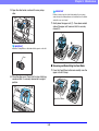
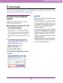
6. Using Patchcode Sheets (Option)
When the optional patchcode decoder is installed, the DR-6050C/7550C/9050C supports Automatic File Separation by detecting
patchcode sheets inserted within a document, and performs batch separation.
• Patchcode sheets must be printed in their original size. The
scanner may not recognize them as patchcode sheets if they
are enlarged or reduced.
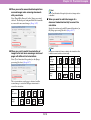
About Patchcode Sheets
Patchcode patterns are printed on the patchcode sheets used to
automatically separate files. Patchcode pattern icons are
registered in the following location when the ISIS/TWAIN
driver is installed.
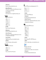
■ Patchcode Pattern Function
There are two types of patchcodes, and their function
changes according to their pattern.
PATCH T
When the scanner recognizes this patchcode printed on a
patchcode sheet, it creates a separate file for the document
that comes after the patchcode sheet. The image of this
sheet can be saved or not, depending on the application’s
settings.
IMPORTANT
PATCH II
• Patchcode sheets can be used only when the application you are
using supports separating files by patchcode patterns.
• Patchcode sheets are data in PDF format. There are four types;
[PATCH II (A4)], [PATCH II (LTR)], [PATCH T (A4)], [PATCH T
(LTR)], organized according to the paper size and pattern.
• Patchcode sheets cannot be used when the MultiStream function
(See “MultiStream” on p. 1-8.) is being used by CapturePerfect
3.0.
When the scanner recognizes this patchcode printed on a
patchcode sheet, it creates a separate file starting from the
patchcode sheet. The image of this sheet is saved,
regardless of the application’s settings.
■ Printing Patchcode Sheets
Open the desired patchcode sheet file with an application
that supports CapturePerfect 3.0 or the PDF file format,
and print the page image only at its original size.
IMPORTANT
• Print (at original size) PATCH T (A4) and PATCH II (A4)
sheets on A4-size paper, or PATCH T (LTR) and PATCH II
(LTR) on LTR paper.
3-20
Chapter 3 Basic Operation
3. On the [Other] tab of the ISIS driver properties, select
How to Use Patchcode Sheets
[Patchcode] from the Batch Separation drop-down
list.
This section describes how to use patchcode sheets with
CapturePerfect 3.0.
1. Print the patchcode sheets on a printer.
IMPORTANT
• Print (at original size) PATCH T (A4) and PATCH II (A4)
sheets on A4 paper, or PATCH T (LTR) and PATCH II (LTR)
on LTR paper.
• The scanner may not recognize the patchcodes if they are
enlarged or reduced.
2. Insert the patchcode sheet in front of the document
that you want to save as a separate file before
placing the documents on the scanner.
Insert patchcode sheets in front of
the documents you want to save as
separate files.
IMPORTANT
If the patchcode decoder is not installed, the [Patchcode] batch
separation setting is not displayed. (See “Batch Separation” on
p. 8-20.)
4. Perform scanning with batch separation enabled.
5. Set the [Type of batch separation] setting to [Scan,
Continue Scanning] or [Skip, Continue Scanning].
Hint
• If [Scan, Continue Scanning] is selected or if the patchcode is
PATCH ll type, the patchcode sheet image is also saved and
scanning continues.
• If [Skip, Continue Scanning] is selected and the PATCH T
pattern is detected, the patchcode sheet image is not saved
and scanning continues.
3-21
Chapter 3 Basic Operation
■ Creating a Patchcode Sheet
To copy a patchcode pattern to create a different size
patchcode sheet, make sure to pay attention to the
following precautions:
IMPORTANT
• Adjust the patchcode so that it fits into the effective area for
detecting patchcode patterns.
(Effective area for detecting
patchcode patterns.)
0.2" (5 mm)
0.2" (5 mm)
Patchcode Patterns
3.9" (100 mm)
0.2" (5 mm)
• When copying a patchcode pattern, the copy should be the
same size as the pattern on the original.
• Be careful to keep patchcode sheets clean. If a patchcode
sheet has been folded or becomes creased, reprint or replace
the sheet.
3-22
Chapter 3 Basic Operation
7. Clearing a Paper Jam or Double Feed Error
If a paper jam or double feed occurs during scanning, a paper jam message appears on the PC and on the scanner’s display panel.
Use the following procedure to clear the paper jam.
CAUTION
• When removing jammed paper, take care not to cut your hands on the edges of the paper.
• Make sure to remove all of the jammed paper. Torn paper remaining in the scanner may cause future jams or damage to the scanner.
• When opening and closing the upper unit, be careful not to get your fingers caught, as this may result in personal injury.
3. Remove the jammed paper.
Paper Jam Handling
IMPORTANT
When a paper jam occurs during scanning, the following
message appears on the display panel, and transport stops.
• If paper has stopped in the midst of ejecting to the eject tray,
raise the upper unit slightly to remove it.
• To remove paper that has stopped inside the scanner, open
the upper unit as far as it will go.
4. Close the upper unit slowly (a). Make sure that the
upper unit is completely closed by pushing on both
edges with both hands until you hear a click (b).
Hint
The displayed error code indicates the location of the paper jam.
For details, see “Error Messages” on p. 6-3.
1. Remove any documents that remain in the eject tray.
2. Press the Open/Close button and gently raise the
upper unit.
Open/Close Button
3-23
Chapter 3 Basic Operation
5. Check to verify the last saved image, and resume
Return the jammed document page to the top of the
document stack yet to be scanned, and press the Start key
to resume scanning.
scanning.
■ When “Press Start Key” Appears
When the Rapid Recovery System is enabled in the ISIS/
TWAIN driver settings, the following message appears on
the display panel after you remove the jammed paper.
IMPORTANT
The Rapid Recovery System setting in the ISIS/TWAIN driver
causes the following process to occur after a paper jam. (See
“[Rapid Recovery System] Check Box” on p. 8-18.)
Start Key
IMPORTANT
• When you press the Start key, the image of the document
page that caused the paper jam is deleted before scanning
resumes.
• If you press the Stop key, the images of pages prior to the
paper jam being detected are saved and the scan ends. In this
case, restart scanning from the document page where the
paper jam occurred, or from the beginning.
• When the Rapid Recovery System is disabled, images
scanned before the paper jam occurs are saved as files,
scanning finishes, finished and an error message is displayed.
In this case, restart scanning from the document page where
the paper jam occurred, or from the beginning.
• When the Rapid Recovery System is enabled, scanning
pauses when a paper jam is detected, and an error message
is displayed.
Handling a Double Feed
When a double feed is detected while scanning, an error
message appears on the PC and on the display panel, and
transport stops.
3-24
Chapter 3 Basic Operation
■ When the Rapid Recovery System is Enabled
IMPORTANT
1. Check the double-fed document page(s).
When a double feed is detected, the following process occurs, and
messages appear according to the Rapid Recovery System setting
in the ISIS/TWAIN driver. (See “[Rapid Recovery System] Check
Box” on p. 8-18.)
Hint
• If attached paper, such as a label on the document page,
appears to be the cause of the double-feed detection, ignore
the detection.
• If two document pages were fed together, rescan the doublefed pages.
2. Press [
] or [ ] to select [IGNORE] or [RETRY]
and press the [Enter] key.
• When the Rapid Recovery System is disabled, images scanned
before the double feed are saved as files, scanning finishes, and
the following error message is displayed.
[IGNORE]:
Saves the image of the page that was detected as a double
feed, and resumes scanning.
[RETRY]:
The display panel appears as below. Return the double-fed
document pages to the tray and press the Start key.
When detecting double feeds by document length
When detecting double feeds ultrasonically
• When the Rapid Recovery System is enabled, scanning pauses
when a double feed is detected, and the following error message
is displayed.
IMPORTANT
• Press the Start key the erase the image that was being
scanned when double feeding was detected, and resume
scanning.
• If you press the Stop key, the images of pages prior to the
double feed being detected are saved and the scan ends. In
this case, restart scanning from the document page where the
double feed is detected, or from the beginning.
■ When the Rapid Recovery System is Disabled
Return the double-fed document pages to the top of the
document stack yet to be scanned, and resume scanning.
3-25
Chapter 4 Other Functions
1. Other Functions and Settings .......................... 4-2
2. Function Description ........................................ 4-4
3. User Mode ....................................................... 4-8
User Mode Operating Procedure ..........................4-8
4. User Mode Functions..................................... 4-10
Chapter 4 Other Functions
1. Other Functions and Settings
The following DR-6050C/7550C/9050C functions are grouped together as Other Functions. For details, refer to the indicated pages.
Operation/Setting Method
Panel Operation Panel Operation
(Not in User Mode) (In User Mode)
ISIS/TWAIN
Applicable Page
SCSI Speed
–
✔
–
p. 4-11
USB Short Packet
–
✔
–
p. 4-11
Imprinter (Optional)
–
–
✔
p. 4-7, p. 8-25
Imprinter Test
–
✔
–
p. 4-12, p. 5-17
Counter (Total Counter)
–
✔
–
p. 4-12
Count (Roller Counter)
–
✔
–
p. 4-12
Count-Only Mode
✔
–
–
p. 4-4
Display Contrast
–
✔
–
p. 4-11
Key Repeat
–
✔
–
p. 4-12
Skew-Detection (Always On)
–
–
–
p. 4-6
Deskew
–
–
✔
p. 8-9
Double-Feed Detection
–
–
✔
p. 4-5, p. 8-19
Double-Feed Detection (Count-Only Mode)
–
✔
–
p. 4-10
Staple Detection
–
–
✔
p. 4-6, p. 8-19
Staple Detection (Count-Only Mode)
–
✔
–
p. 4-10
Staple Detection Level Setting
–
✔
–
p. 4-6, p. 4-10
Stand-by Mode
–
✔
–
p. 4-11
Long-Document Mode
–
✔
–
p. 3-4
Tray Position
–
✔
–
p. 3-6, p. 4-11
Folio Scan
–
–
✔
p. 4-6, p. 8-9
Buzzer (Beeper) Control
–
✔
–
p. 4-10
Verify Scan
✔
–
✔
p. 4-4
Manual Feed Mode
–
✔
–
p. 3-11, p. 4-11
4-2
Chapter 4 Other Functions
Hint
• The Operation/Setting Methods are as follows:
Panel Operation: The operation or setting is performed using the control panel keys.
User Mode: The scanner function setting is made as a User Mode selection.
ISIS/TWAIN: The function is an ISIS/TWAIN driver scanning setting.
• The page count for the Verify Scan operation is entered using the control panel keys, and the operation is then executed by selecting Verify
Count from the ISIS/TWAIN driver.
4-3
Chapter 4 Other Functions
2. Function Description
The Other Functions are described below. See “User Mode” on p. 4-8, for descriptions of the functions set from the User Mode.
■ Count-Only Mode
IMPORTANT
Counts the number of loaded document sheets by simply
feeding them through the scanner.
To reset the page counter, press the Count Clear key for
approximately two seconds while the Count Only key is
lit.
Hint
The Count-Only mode is executed by the Count Only key on the
control panel, and can be used to count document sheets even
when no computer is connected.
1. Place the documents into the tray.
Count Clear
Key
2. Press the Count Only key on the control panel.
Count Only
Key
■ Verify Scan
The scanner compares the document page count obtained
from the Count-Only mode (or entered manually) with the
actual count of document pages scanned, and an error
message is displayed if the counts do not match.
The Count Only key lights green when the Count-Only
mode is enabled.
1. Setting the Count.
Hint
3. Press the Start key to start scanning and count the
The document page count can be specified by using the count
obtained from the Count-Only mode or by pressing the [ ] and
[ ] keys to enter a number.
loaded document sheets.
2. Select Verify Count in the ISIS/TWAIN driver
settings. (See “[Verify Count] Check Box” on p. 8-22.)
4-4
Chapter 4 Other Functions
3. Press the Start Key to start scanning.
IMPORTANT
“Verifying…” is displayed.
• The message that appears when a double feed is detected
depends on the Rapid Recovery System setting specified in
the ISIS/TWAIN driver. See “When the Rapid Recovery
System is Enabled” on p. 3-25 for details.
Hint
If the specified count is exceeded while scanning, or if the
scanned count does not reach the specified count when
scanning is finished, an error is displayed.
• Double feed detection in the Count-Only mode is set in the
User Mode, and double feeds are detected ultrasonically.
(See “Double-Feed Control Setting” on p. 4-10.)
The specified count is exceeded while scanning
Detecting Double Feeds by Document Length
This detection method is effective when scanning
documents with pages of the same size. The length of the
first page scanned serves as a standard for comparing
subsequent pages, and when a page is detected to be
approximately 1.4 inches (35 mm) longer or shorter than
the standard, a double feed is detected and document
transport is stopped.
Scanning finishes without reaching the specified count
■ Double-Feed Detection
Ultrasonic Double-Feed Detection
This detection method is effective when scanning
documents with pages of different sizes. The space
between overlapping pages is detected ultrasonically, and
document transport stops when a double feed is detected.
The scanner can detect double feeds. Two detection
methods are used: comparison of document lengths, and
ultrasonic detection of spacing between documents, which
is set in the ISIS/TWAIN driver.
IMPORTANT
• Ultrasonic double-feed detection works only when the
document pages overlap by at least two inches (50 mm).
• If documents stick together due to static electricity, Ultrasonic
Double-Feed Detection may not function correctly.
• If the presence of adhesive notes or labels on pages is
detected as a double feed and you do not want to remove
them for scanning, a non-detection zone can be specified in
the ISIS/TWAIN driver settings. (See “Double Feed Detection”
on p. 8-19.)
4-5
Chapter 4 Other Functions
■ Skew Detection
• Staple detection may not operate properly in the following
cases where bending does not occur in documents.
– The document is stapled at two or more corners.
– The document is size smaller than STMT/A5.
– The position of the left or right document guide has been
changed, and the document has been shifted to the left or
right side. (See “Adjusting the Document Guides” on p. 3-8.)
If a long document page becomes skewed as it is fed, the
page may press against the edge of the feed inlet or
transport path and be damaged.
When the scanner detects that a skewed page is contacting
the edge of the transport path, an error message is
displayed and transport stops.
Hint
• Staple detection is controlled in the ISIS/TWAIN driver, and
the detection level can be set in the User Mode. (See “Staple
Detection Level Setting” on p. 4-10.)
• Staple detection for the Count-Only mode can be set in the
User Mode. (See “Staple Detection Setting” on p. 4-10.)
IMPORTANT
• A page that becomes skewed while it is fed is only detected by
the sensors as skewed if it contacts the edge of the transport
path during scanning.
• Note that the ISIS/TWAIN driver has a Deskew function that
can detect a skewed document from the scanned image, and
straighten it.
■ Folio Scan
Use Folio Scan to scan very large documents (up to 22" ×
34"/A1 size) by folding each document sheet and scanning
the front and back. The resulting images are then
recombined to reconstruct an image of the entire page.
■ Staple Detection
When sensors at both sides of the feed inlet detect the bent
corner of a stapled document, an error message appears
and feeding stops.
Front
(when
folded)
Back
(when
folded)
Separation
Off Key
Reconstructed Image
IMPORTANT
• Folio scanning requires that you feed each page manually
(The Separation Off key is lit).
• Fold each page with a sharp, straight crease. Otherwise, the
paper may jam or the image may be misaligned.
IMPORTANT
• Staple detection detects the bent corner that occurs when one
of the four corners of a document has been stapled.
4-6
Chapter 4 Other Functions
• Seam artifacts may appear in the reconstructed image
because of the crease line or differences in the loading
position of each side.
• Load the document with the crease line on the right side.
• The scan image of the front side becomes the left half of the
reconstructed image.
• The maximum document size for Folio Scan is 22" × 34"/A1.
• 22" × 34"/A1 document pages should be folded lengthwise
and scanned with the following settings:
Scanner: Long Document Mode [ON1]
Page Size: Auto-Detection
• If scanning is performed when Long Document Mode is
enabled, the image may be lost. Set Long Document Mode to
[OFF] except when scanning 22" × 34"/A1 document pages.
• If scanning is performed with the scanning mode set to color,
image quality set to [Image quality priority], and scanning side
set to [Duplex], the image may be lost. If this occurs, scan by
using black and white, reducing the image quality, or setting
the scanning side to [Simplex].
Hint
Folio Scan is performed by setting the scanning side to [Folio]
in the ISIS/TWAIN driver. (See p. 8-9.)
■ Imprinter (Optional)
An imprinter that prints on scanned documents is available
as an option. For details, contact your dealer or service
representative.
Hint
• The text to print and the printing position can be specified in
the ISIS/TWAIN driver. (See p. 8-25.)
• Even if the imprinter is not installed, you can add a specified
text string onto scanned images.
4-7
Chapter 4 Other Functions
3. User Mode
The User Mode provides the user with the capability to change certain scanner functions.
User Mode Operating Procedure
User Mode operations are controlled by the following
procedure.
Hint
Operating procedures differ according to User Mode function. For
details, refer to the indicated pages.
1. Press the Menu key on the control panel.
Menu Key
The User Mode is activated.
2. Press the [
] and [
] keys to select the User Mode
function.
The User Mode functions are displayed in the following
sequence.
4-8
Chapter 4 Other Functions
3. Press [Enter].
Enter Key
The current setting is indicated by blinking square brackets
[ ].
4. Press the [
] or [ ] key to select [ON2], [ON1] or
[OFF], and press [Enter] to accept the selection.
5. Press the [Stop] key to exit the User Mode.
4-9
Chapter 4 Other Functions
4. User Mode Functions
The following functions are available in the User Mode.
■ Buzzer (Beeper) Control Setting
■ Staple Detection Level Setting
The beeper (“buzzer”) sounds when you press the control
panel keys and when a scanning error occurs.
ON2: The beeper sounds when a scanner error occurs, and
when a control panel key is pressed.
ON1: The beeper sounds when a scanner error occurs.
OFF: The beeper never sounds.
Sets the staple detection sensitivity level.
[1] is the default setting, [2] provides higher sensitivity,
and [0] provides lower sensitivity.
■ Long Document Mode Setting
■ Double-Feed Control Setting
You can enable this mode to detect and scan document
pages up to 118.11" (3 m) long when the Auto Detection
page size setting is selected. (See “Long Document Mode
Setting” on p. 3-4.)
ON2: Automatically detects page sizes when scanning
documents up to 118.11" (3 m) long.
ON1: Automatically detects page sizes when scanning
documents up to 39.37" (1 m) long.
OFF: Automatically detects page sizes when scanning
documents up to 17.01" (432 mm) long.
Select whether double-feed detection is enabled when the
Count-Only mode is enabled. If you set DBL Feed Control
to [ON], double feeds are detected during feeding in the
Count-Only mode. (See “Double-Feed Detection” on
p. 4-5.)
■ Staple Detection Setting
Hint
Feeding a document longer the maximum detectable page size
for Auto Detection causes a paper jam indication, and transport
stops.
Select whether staple detection is enabled when the CountOnly mode is enabled. (See “Staple Detection” on p. 4-6.)
ON: Detects staples in the Count-Only mode.
OFF: Does not detect staples in the Count-Only mode.
4-10
Chapter 4 Other Functions
■ Continuous Manual Feeding Mode Setting
■ SCSI Speed Setting
This mode disables automatic feeding by the pickup roller,
so that the loaded document stack must be fed by hand one
sheet at a time by the operator. (See “Continuous Manual
Feeding Mode” on p. 3-12.)
ON: The pickup roller is disabled.
OFF: Documents are fed by the pickup roller.
Selects the scanner’s SCSI transfer speed.
If the scanner does not operate normally with the default
[20] (20 MBytes/s) speed, change this setting to reduce the
speed to [10] (10 MBytes/s) or [5] (5 MBytes/s).
■ USB Short Packet Setting
■ Stand-by Mode Setting
If the scanner does not operate normally when using the
USB interface, change this setting to [OFF].
Selects the amount of time (240, 60 or 10 minutes) from
when the scanner is last used to when the Stand-by mode
is activated.
■ Tray Position Setting
■ Display Language Setting
The document feed tray should be set to fit the number of
document sheets to be loaded. (See “Preparing the
Document Feed Tray” on p. 3-6.)
For the DR-6050C
0: Up to 300 sheets
1: Up to 100 sheets
For the DR-7550C/9050C
0: Up to 500 sheets
1: Up to 300 sheets
2: Up to 100 sheets
Selects English, Japanese or French for the language to
display on the control panel.
EN: English display panel
JP: Japanese display panel
FR: French display panel
■ Display Contrast Adjustment
Use to adjust display panel contrast.
4-11
Chapter 4 Other Functions
■ Key Repeat Setting
Selects the panel display method.
ON: The panel display scrolls when a key is pressed
continuously.
OFF: The panel display scrolls each time a key is pressed.
Hint
Key repeat is valid in the following situations.
• When using the Job Function
• When selecting each of the functions in the User Mode
■ Total Counter
Displays the lifetime total number of document pages fed
by the scanner.
■ Roller Counter
Displays the number of document pages fed since roller
installation or replacement (pickup, feed, and retard
rollers). Make sure to reset this counter when replacing the
rollers. (See “Checking and Resetting the Page Counter”
on p. 5-5.)
■ Imprinter Test
When the optional imprinter is installed, this function
executes a test printing of the imprinter. (See “Performing
an Imprinter Test” on p. 5-17.)
4-12
Chapter 5 Maintenance
1. Regular Maintenance....................................... 5-2
Cleaning the Scanner............................................5-2
Cleaning the Sensors............................................5-2
Cleaning the Scanning Glass and Rollers.............5-3
Power Outlet .........................................................5-4
2. Replacing the Transport Rollers ...................... 5-5
Roller Replacement Cycle.....................................5-5
Checking and Resetting the Page Counter...........5-5
Removing and Reinstalling the Rollers .................5-7
3. Imprinter Ink Cartridge Replacement and
Cleaning......................................................... 5-13
About the Imprinter..............................................5-13
Replacing Ink Cartridges.....................................5-13
Specifying the Printing Position...........................5-15
Cleaning the Imprinter.........................................5-16
Imprinter Testing .................................................5-17
Chapter 5 Maintenance
1. Regular Maintenance
To maintain scanning quality, routinely clean the scanner as described below.
CAUTION
• Do not use spray cleaners to clean the scanner. Precision mechanisms may get wet and malfunction.
• Never use paint thinner, alcohol, or other organic solvents to clean the scanner. Such solvents may deform or discolor the exterior of the
scanner, and cause other damage.
• When opening and closing the upper unit, be careful not to get you fingers caught, as this may result in personal injury.
■ Cleaning the Document Feed Inlet and
Transport Path
Cleaning the Scanner
■ About the Cleaning Cloth
Dust or paper particles in the document feed inlet or inside
the scanner can cause spots to appear in scanned images.
Use compressed air to periodically clean dust and paper
particles from the inlet and the inside of the scanner. After
completing large scanning jobs, turn OFF the scanner and
clean out any paper particles.
Use the cleaning cloth supplied with the scanner to clean
its interior.
■ Cleaning the Scanner Exterior
To clean the outside of the scanner, use a cloth moistened
with water or mild detergent solution. Wring out the cloth
thoroughly, and use a clean dry cloth to wipe the scanner
dry.
Cleaning the Sensors
Dust and debris that collects on the sensors may cause
documents to be recognized incorrectly. Clean the sensors
periodically using a blower, etc. so that dust and debris do not
collect on them.
Main unit inner lower side
Sensors
Sensors
5-2
Chapter 5 Maintenance
3. Press the Open/Close button and carefully raise the
Main unit inner upper side (Upper Unit)
upper unit until it stops.
Sensors
Open/Close Button
Cleaning the Scanning Glass and Rollers
4. Wipe any dust off the scanning glass with a cleaning
If scanned images contain spots or documents become dirty
after scanning, the scanning glass or transport rollers inside
the scanner may be dirty. Please clean periodically.
cloth or a clean, dry cloth.
Make sure that you clean both scanning glasses, the one
below and one above.
IMPORTANT
CAUTION
Scratches on the scanning glass may cause spots or streaks on
scanned images, as well as feeding errors. If you find a scratch on
the scanning glass, contact your local authorized Canon dealer or
service representative to have the glass replaced.
Never spray mild detergent or water directly on the scanning
glasses. The spray could penetrate below the glass, and
contaminate the internal light source and lenses.
1. Turn the power switch off, and disconnect the power
plug from the power outlet.
2. Close the document eject tray extension if it is open.
Scanning
Glass
5-3
Chapter 5 Maintenance
5. Wipe the rollers using a moistened and firmly wrung-
9. Gently lower the upper unit (a). Press down on both
out cloth while rotating the rollers.
The rollers are located at the positions indicated in the
figure below.
sides of the upper unit to ensure that it is securely
closed (b).
Pickup Roller
Feed Roller
Transport
Roller
Platen
Roller
Retard Roller
IMPORTANT
If paper jams or double feeds occur frequently even after
cleaning the rollers, the probable cause is the roller friction. If
this happens, replace the rollers. Contact your service
representative.
6. Remove the Pickup Roller, Feed Roller, and Retard
Roller. (See “Removing and Reinstalling the Rollers”
on p. 5-7.)
IMPORTANT
Wipe the Pickup Roller, Feed Roller, and Retard Roller after
removing them.
Power Outlet
If you leave the power plug connected to the power outlet for
a long period of time, dust may accumulate at the power
outlet, and cause a fire or electrical shock. Clean the power
plug and power outlet regularly.
7. Wipe the rollers that you removed using a moistened
and firmly wrung-out cloth.
8. Replace the rollers that you removed. (See
“Removing and Reinstalling the Rollers” on p. 5-7.)
5-4
Chapter 5 Maintenance
2. Replacing the Transport Rollers
As the rollers start to wear out, feeding quality declines, and document feed errors, such as paper jams, become more likely.
If document feed errors continue to occur after cleaning the rollers, purchase the Roller Replacement Kit and replace the transport
rollers (pickup, feed, and retard rollers).
■ Roller Replacement Kit
Roller Replacement Cycle
The Roller Replacement Kit consists of replacement
pickup, feed, and retard rollers. For details, contact your
local authorized Canon dealer or service representative.
Product Name: Roller Replacement Kit
Product Code: 4009B001
The feeding rollers are consumables that must be replaced
after feeding about every 250,000 pages.
When the rollers have fed more than 250,000 pages, a roller
replacement message appears on the display panel whenever
the scanner is turned ON. When the scanner is configured to
reboot with the computer, a roller replacement message also
appears on the computer screen.
Pickup Roller
Feed Roller
IMPORTANT
• When the roller replacement message appears, purchase the
Roller Replacement Kit and replace the rollers by following the
relevant steps in the removing and reinstalling procedures.
– (See “Removing and Reinstalling the Pickup Roller” on p. 5-7.)
– (See “Removing and Reinstalling the Feed Roller” on p. 5-8.)
– (See “Removing and Reinstalling the Retard Roller” on
p. 5-10.)
• When the rollers start to wear out, problems such as paper jams
and document misfeeds may occur more frequently. If this
happens, replace the rollers, regardless of the page count of the
roller usage counter.
• Messages on the display panel can be cleared by pressing the
Count Clear key. However, the messages will continue to be
displayed each time the scanner is turned ON until the roller
counter is reset.
• Make sure to reset the roller counter when replacing the rollers.
(See “Checking and Resetting the Page Counter” on p. 5-5.)
Retard Roller
Checking and Resetting the Page Counter
The roller usage counter can be checked and reset using the
Roller Counter in the User Mode setting.
IMPORTANT
• This counter shows the number of pages transported by the
currently installed feed rollers. Make sure to reset the counter
when you replace the rollers.
• The Total Counter shows the total number of pages fed over the
life of the scanner, and cannot be reset.
5-5
Chapter 5 Maintenance
1. Press the Menu key on the control panel to activate
The counter reset mode is activated.
the User Mode.
4. Press the [
] key to select [RESET], and press
[Enter].
The counter is reset to zero.
Menu Key
5. Press the [Stop] key to exit the User Mode.
2. Press the [
] key twice to display [Roller Counter].
3. Check the number of pages fed by the rollers, and
press [Enter].
Enter Key
5-6
Chapter 5 Maintenance
2. Open the roller cover.
Removing and Reinstalling the Rollers
Follow the procedure shown below to remove and reinstall
the rollers when you need to clean or replace the Pickup,
Feed, or Retard Rollers.
CAUTION
• Turn OFF the power switch, and disconnect the power plug from
the power outlet when you remove or reinstall the rollers. Leaving
the power turned ON may result in an electric shock.
• Do not place excessive force on the rollers when removing or
reinstalling the rollers. Deformation of the rollers may cause feed
errors.
3. Open the roller holder.
Pickup Roller
Feed Roller
Retard Roller
Hint
The roller holder returns to its original position when released.
■ Removing and Reinstalling the Pickup Roller
4. Remove the pickup roller.
1. Press the Open/Close button and carefully raise the
upper unit until it stops.
Open/Close Button
5-7
Chapter 5 Maintenance
5. Open the roller holder, and insert the new pickup
IMPORTANT
roller.
Failure to firmly close the roller holder and roller cover may
cause a feed error. Always be sure to check that the roller holder
and roller cover are closed.
7. Gently lower the upper unit (a). Press down on both
sides of the upper unit to ensure that it is securely
closed (b).
IMPORTANT
Install the Pickup Roller so that side with the gear is on the left.
Gear
■ Removing and Reinstalling the Feed Roller
1. Press the Open/Close button and carefully raise the
upper unit until it stops.
6. Close the roller cover. Check that it makes a latching
sound and that it is securely returned to its original
position.
Open/Close Button
5-8
Chapter 5 Maintenance
2. Open the roller cover.
5. Remove the feed roller.
3. Pull the roller lock lever down.
6. Place the new feed roller on the pin.
4. Slide the feed roller to the right, and then pull them
7. Put the feed roller in place (a), and align the notch in
towards you.
the roller’s axle with the shaft on the scanner (b).
5-9
Chapter 5 Maintenance
10. Gently lower the upper unit (a). Press down on both
8. Push the roller lock lever up to lock the feed roller.
sides of the upper unit to ensure that it is securely
closed (b).
9. Close the roller cover. Check that it makes a latching
sound and that it is securely returned to its original
position.
■ Removing and Reinstalling the Retard Roller
1. Press the Open/Close button and carefully raise the
upper unit until it stops.
IMPORTANT
Failure to firmly close the roller cover may cause a feed error.
Always be sure to check that the roller cover is closed.
Open/Close Button
5-10
Chapter 5 Maintenance
2. Grasp the roller cover with your fingers, and pull it up
5. Set the retard roller into place in the scanner.
to remove it.
6. Align the notches in the roller with the shaft pins in the
3. Push the roller lock lever up (a) and move it to the left
scanner, then slide the roller lock lever in the
direction indicated by the arrow.
(b) to unlock the roller.
4. Remove the retard roller.
7. Pull the roller lock lever down to lock the retard roller
in place.
5-11
Chapter 5 Maintenance
10. Gently lower the upper unit (a). Press down on both
8. Replace the roller cover.
sides of the upper unit to ensure that it is securely
closed (b).
9. Push the front of the roller cover in. Check that it
makes a latching sound and that it is securely
returned to its original position.
CAUTION
Make sure that the hook is completely latched and the roller
cover is not loose. If the roller cover is loose, the Document
Feed Tray will catch on it causing the scanner to malfunction.
5-12
Chapter 5 Maintenance
3. Imprinter Ink Cartridge Replacement and Cleaning
When the optional imprinter is used, printing will become faint or nonexistent when the ink is depleted. It is recommended to keep
a spare ink cartridge on hand.
About the Imprinter
Replacing Ink Cartridges
The ink cartridge for the imprinter that prints on scanned
documents is installed in the following location.
Replace the ink cartridge using the following procedure.
IMPORTANT
After replacing an ink cartridge, run a test print to confirm proper
printing. (See “Imprinter Testing” on p. 5-17.)
1. Spread the document guides all the way to the left
and right.
2. With your finger, push in the area of the imprinter
cover shown by the arrow to release it.
The imprinter cover unlocks and opens to the front.
■ Preparing an Ink Cartridge
Use one of the following red, blue or green HP ink
cartridges. For details, contact your local authorized
Canon dealer or service representative.
Product Name: Ink Cartridge (Blue)
Product Code: 3693A002
Product Name: Ink Cartridge (Red)
Product Code: 3693A003
Product Name: Ink Cartridge (Green)
Product Code: 3693A004
5-13
Chapter 5 Maintenance
3. Open the imprinter cover until it makes contact with
6. Peel off the seal covering the nozzles of a new ink
the eject tray.
cartridge.
CAUTION
Hint
Peel off the seal covering the nozzles of a cartridge only if you
are going to use it immediately. Also, avoid touching the metal
contacts or nozzles of the ink cartridge.
Perform the steps that follow with the imprinter cover fully open.
4. Pull the lock lever outward (a) to release the ink
cartridge lock (b).
7. Install the new cartridge with the nozzles facing to the
right.
5. Remove the ink cartridge.
5-14
Chapter 5 Maintenance
10. Close the imprinter cover.
8. Push the ink cartridge as indicated by the arrow until
it clicks into place.
With your finger, push in the area of the imprinter cover
shown by the arrow to lock it.
9. Adjust the carriage position by moving it left or right,
then make sure you can feel it click in. (See
“Specifying the Printing Position” on p. 5-15.)
Hint
The imprinter cover will not close unless the carriage is correctly
aligned with a positioning hole. If it will not close, check the
position of the carriage.
Positioning Holes
(15 Locations)
IMPORTANT
When closing the imprinter cover, make sure that it is locked so
that it will not open unexpectedly. An error message appears on
the display panel if the imprinter cover is open.
Hint
Specifying the Printing Position
If you do not feel it click in, the carriage is not aligned correctly
with a positioning hole. Always move the carriage to a position
where it clicks in.
Manually specify the printing position in the horizontal
direction of the document.
To do this, move the carriage left or right and align it with one
of the 15 positioning holes.
5-15
Chapter 5 Maintenance
1. Roughly align the right edge of the lock lever with the
Cleaning the Imprinter
desired printing position.
■ Cleaning the Guide Plate
Ink that collects on the guide plate inside the optional
imprinter may stain the documents when they are scanned.
Clean off the ink with water and a mild detergent on a soft
cloth that has been firmly wrung-out, and then thoroughly dry
it with a dry cloth.
Guide Plate
Hint
The position of the right edge of the lock lever indicates the
current printing position.
2. Finely adjust the carriage position by moving it left or
right, then make sure you can feel it click in.
Positioning Holes
(15 Locations)
■ Cleaning the Ink Cartridges
If the imprinter print head nozzles are dirty, printing may
become streaked or spotty. To prevent this, periodically
remove the ink cartridge and clean the print head with a soft,
dry cloth or cotton swab.
Hint
• If you do not feel it click in, the carriage is not aligned correctly
with a positioning hole. Always move the carriage to a position
where it clicks in.
• The imprinter cover will not close unless the carriage is
correctly aligned with a positioning hole. If it will not close,
check the position of the carriage.
5-16
Chapter 5 Maintenance
2. Press the Menu key on the control panel.
CAUTION
Do not touch the metal contacts on the ink cartridge. Doing so may
cause poor connections, resulting in poor print quality.
Menu Key
Imprinter Testing
The User Mode is activated.
After replacing an ink cartridge or cleaning the print head, perform
a test print to confirm proper printing. Test printing is performed by
the “Imprinter Test” User Mode selection.
IMPORTANT
3. Press the [
Before performing an Imprinter Test, load a sheet of paper into the
Document Feed Tray.
] key once to display “Imprinter Test”.
■ Performing an Imprinter Test
Use the following procedure to execute the Imprinter Test.
4. Press [Enter].
1. Load a sheet of paper into the Document Feed Tray
for test printing.
Enter Key
5-17
Chapter 5 Maintenance
The Imprinter Test is enabled.
5. Press the [
] key to select [OK], and press [Enter].
The test print is executed.
IMPORTANT
If no paper is loaded for test printing, the imprinter test finishes
without printing.
6. Press the [Stop] key to exit the User Mode.
5-18
Chapter 6 Practical Examples
1. Messages ........................................................ 6-2
Status Display .......................................................6-2
Error Messages.....................................................6-3
2. Troubleshooting ............................................... 6-5
Trouble Categories................................................6-5
Problem and Solution............................................6-5
3. Uninstalling the Software ................................. 6-9
Uninstalling the ISIS/TWAIN Driver.......................6-9
Chapter 6 Practical Examples
1. Messages
There are two types of display panel messages: “status indicator messages” and “error messages” that appear when the scanner
encounters a problem.
■ Sleeping...
Status Display
The following messages appear on the display panel to
indicate the scanner’s operating state:
■ Counting...
Status: The scanner is entering the Sleep mode. Press any
key to recover.
■ Please wait...
Status: Operating in Count-Only mode.
■ Press Start Key
Status: The scanner is busy processing. Wait until the
display changes.
■ Verifying…
Status: Waiting. Load a document and press the Start key.
■ Ready
Status: The scanner is verifying a scan.
■ Replace Roller
Status: The scanner is ready to use.
■ Scanning...
Status: It is time to replace the rollers (the number of fed
pages has exceeded 250,000). (See “Roller Replacement
Cycle” on p. 5-5.)
Status: Scanning is in progress.
6-2
Chapter 6 Practical Examples
Hint
Error Messages
The displayed error code indicates the location of the paper jam.
• P001, P002: The document is jammed near the feed inlet.
• P004: The document is jammed inside the scanner.
• P006, P007: The document is jammed near the eject outlet.
* P001, P006 can be considered to be due to the document feed
speed being too fast or the leading edge of the document not
feeding correctly.
When one of the following messages appears on the display
panel, an error has occurred in the scanner. Follow the
indicated procedure to resolve the error.
■ Check Imprinter
■ Call for Service
Error Code: H001
Problem: No ink cartridge is installed in the imprinter.
Solution: Install an ink cartridge.
Error Code: Exxx
Problem: Internal scanner error.
Solution: Turn the power OFF, and restart the scanner. If
this does not solve the problem, make a note of the error
code, and contact your Canon service representative.
■ Cover Open
■ Skew Detected
Error Code: C001
Problem: The scanner’s upper unit is open.
Solution: Close (lower) the upper unit. (See p. 5-4.)
Error Code: C009
Problem: The imprinter cover is open.
Solution: Close the imprinter cover. (See p. 5-15.)
Error Code: C010
Problem: The pickup roller cover is open.
Solution: Close the pickup roller cover. (See p. 5-8.)
Error Code: J018
Problem: A skewed document page contacted the wall of
the transport path.
Solution: Remove and reposition the document page.
■ Jam
Error Code: Pxxx
Problem: Paper has jammed.
Solution: Open the upper unit and remove the jammed
paper. (See p. 3-23.)
6-3
Chapter 6 Practical Examples
■ Double Feed
■ Tray Error
Error Code: D002
Problem: A double feed was detected by the document
length.
Solution: Remove the double fed document page(s),
return them to the Document Feed Tray, and scan again.
(See p. 3-24.)
Error Code: D004
Problem: A double feed was detected ultrasonically.
Solution: Remove the double fed document page(s),
return them to the Document Feed Tray, and scan again.
(See p. 3-24.)
Error Code: E021
Problem: An error has occurred with the Document Feed
Tray.
Solution: Turn the power OFF, and restart the scanner.
■ Count Mismatch
Error Code: U001
Problem: The specified count has not yet been reached.
Solution: Check the document count, and scan again.
Error Code: U002
Problem: Scanning finished without reaching the
specified count.
Solution: Check the document count, and scan again.
■ Double Feed (Rapid Recovery System)
Problem: Double feeding of document pages has been
detected while scanning with the Rapid Recovery System
enabled.
Solution: Remove the double fed document page(s),
return them to the Document Feed Tray, and scan again.
(See p. 3-24.)
■ Staple Detected
Error Code: J001
Problem: A stapled document has been detected.
Solution: Remove the staple(s), and rescan the document.
6-4
Chapter 6 Practical Examples
2. Troubleshooting
This section describes the problems that may occur during use of the scanner and how to solve them.
If this does not solve the problem, consider the following
possible causes:
Trouble Categories
The following trouble categories are addressed:
• The Scanner Does Not Turn ON (See p. 6-5)
• The Scanner Is Not Recognized (Connecting via USB)
(See p. 6-5)
• The Scanner Is Not Recognized (Connecting via
SCSI) (See p. 6-5)
• Scanning Is Not Performed (See p. 6-6)
• Slow Scanning Speed (See p. 6-6)
• Documents Do Not Feed Properly (See p. 6-7)
• Saved Image Files Do Not Open (See p. 6-7)
• Scanning Results Are Not as Expected (See p. 6-7)
It you cannot resolve a problem, contact your local authorized
Canon dealer or your service representative.
Cause
Solution
Cause
Solution
Cause
Solution
The scanner does not support your USB
interface.
This product is not guaranteed to operate with
all types of USB interfaces. Contact your local
authorized Canon dealer or service
representative for more information.
The scanner does not support the USB
cable.
Use the USB cable provided with the scanner.
The USB hub is not compatible with the
scanner.
Remove the USB hub.
■ The Scanner Is Not Recognized (Connecting
via SCSI)
Problem and Solution
■ The Scanner Does Not Turn ON
If the scanner’s SCSI connection is not recognized, first
confirm the following:
✔ Are the scanner and PC connected correctly using the
proper cable?
✔ Is the scanner’s power switch turned ON?
✔ Is the SCSI card in the PC operating properly?
✔ Was the PC turned ON before the scanner?
If the scanner does not turn ON, first confirm the
following:
✔ Is the power cord connected correctly?
✔ Is the power cord inserted into the power outlet?
■ The Scanner Is Not Recognized (Connecting
via USB)
IMPORTANT
If the scanner’s USB connection is not recognized, first
confirm the following:
✔ Are the scanner and PC connected correctly using the
proper cable?
✔ Is the scanner’s power switch turned ON?
When using the SCSI connection, if the scanner is turned ON
after the PC, it may not be properly recognized by the PC.
6-5
Chapter 6 Practical Examples
If this does not solve the problem, consider the following
possible causes:
Cause
Solution
Cause
Solution
The SCSI card is not compatible with the
scanner.
Use a recommended SCSI card. (See p. 2-3.)
The scanner’s SCSI ID is identical to the
SCSI ID of another device.
Check the SCSI IDs of all SCSI devices
connected to the system and set a unique SCSI
ID for the scanner.
Cause
Solution
The terminator is not set correctly.
When another SCSI device is connected
between the scanner and the PC, that device’s
terminator must be disabled (set to OFF).
Cause
There is a problem with another SCSI
device that is connected in the daisy
chain.
Do not use the daisy chain connection
configuration.
Solution
IMPORTANT
• If the scanner does not operate because of a system error,
turn the scanner OFF and wait at least 10 seconds before
turning it back ON. If errors continue to occur, reboot the
scanner and computer.
• When scanning with configurations that use a large amount of
the computer’s memory, scanning will be performed properly
for the first scan. However, if a second scan is performed with
the same configurations, an error may occur due to insufficient
memory and scanning may not be possible. In such cases,
restart the application you are using and change the
configurations before scanning again.
■ Slow Scanning Speed
If the scanning speed is slow, first confirm the following:
Scanning may be slow if the USB interface does not
support Hi-Speed USB 2.0.
✔ Does the PC’s USB interface support only Full-Speed
USB 1.1?
✔ Is the USB cable you are using the one that was
supplied with the scanner (Hi-Speed USB 2.0
compliant)?
✔ Is a USB 1.1-compliant device connected to the USB
hub at the same time?
■ Scanning Is Not Performed
If this does not solve the problem, consider the following
possible causes:
If scanning does not start when it should, first confirm the
following:
✔ Are the scanner and PC correctly connected with the
proper cable?
✔ Is the scanner’s power switch turned ON?
Cause
Solution
If this does not solve the problem, consider the following
possible causes:
Cause
Cause
Solution
Solution
The ISIS/TWAIN driver and Job
Registration Tool are not installed
correctly.
Uninstall and then reinstall the ISIS/TWAIN
driver and Job Registration Tool.
Cause
Solution
6-6
Other applications are running in the
background on your PC.
Quit all other applications that are running.
Resident applications, such as anti-virus
software, are draining memory resources.
Quit all resident applications.
Temporary files cannot be created in the
TEMP folder, as there is not enough free
space on the hard disk.
Delete unnecessary files on the hard disk to
increase free space.
Chapter 6 Practical Examples
■ Documents Do Not Feed Properly
■ Saved Image Files Do Not Open
If a document does not feed properly, first confirm the
following:
✔ Are pages sticking together because of static electricity
or another cause?
✔ Are you attempting to scan a document with size, paper
thickness or quality that is not supported by the
scanner? (See “Documents” on p. 3-3.)
✔ Are the feed rollers dirty?
✔ Are the feed rollers worn out?
If image files saved by CapturePerfect 3.0 cannot be
opened by another application, first confirm the following:
✔ Does the application you are using support
CapturePerfect 3.0 image file types (*.bmp, *.tif, *.jpg
and *.pdf)?
If this does not solve the problem, consider the following
possible causes:
Cause
IMPORTANT
Solution
• Double feeding occurs when document pages stick together,
and incompatible paper thickness or quality can cause paper
jams. Check your documents carefully before loading.
• Replacement rollers can be purchased as consumables. If
performance is not improved after cleaning the rollers, contact
your local Canon dealer or service representative to purchase
a Roller Replacement Kit, and replace the rollers (pickup, feed
and retard rollers). (See “Replacing the Transport Rollers” on
p. 5-5.)
Cause
Solution
If this does not solve the problem, consider the following
possible problems and causes:
Problem
Cause
Solution
The application does not support multipage TIFF files.
Open the files using an application that
supports multi-page TIFF files, or save the
images as single-page TIFF files using
CapturePerfect 3.0.
The compression format used by
CapturePerfect 3.0 is not supported.
Open the image file with CapturePerfect 3.0,
set the compression format to [None], and save
it again.
■ Scanning Results Are Not as Expected
Documents do not feed.
The Continuous Manual Feed Mode is
enabled.
Set the Continuous Manual Feed Mode to
[OFF] from the User Mode. (See “Continuous
Manual Feeding Mode Setting” on p. 3-12.)
If the scanned images do not appear as expected, one or
more ISIS/TWAIN driver settings may be incorrect, or
your application may not support certain scanner
functions.
Problem
Cause
Solution
6-7
The scanned image is too dark (or faint).
The [Brightness] setting is not set to an
appropriate value.
If the image is too dark, set a higher brightness
setting, or if the image is too faint, set a lower
brightness setting.
Chapter 6 Practical Examples
Problem
Cause
Solution
Cause
Solution
Problem
Cause
Solution
Problem
Cause
Solution
Problem
Cause
Solution
Text or images from the back side of your
document appear in the scanned image.
Brightness may be set too low.
Increase the Brightness setting. Or, enable the
[Prevent Bleed Through/Remove
Background] setting.
The paper is too thin.
Photocopy the document, and scan the copy.
Problem
Cause
Solution
Double-sided scanning is not possible.
Scanning Side is set to [Simplex].
Set Scanning Side to [Duplex].
If the Scanning Side is set to [Skip blank
page], images of blank pages are not saved.
Problem
Cause
A black margin appears around the
scanned document.
A document smaller than the preset paper
size has been scanned. Or, the loaded
document has shifted out of position.
Choose one of the following:
(1) Set [Page size] to [Auto-detection].
(2) Adjust the margin setting in a single
direction.
(3) Enable Border Removal.
Solution
Problem
The scanned image is skewed. (skew)
The document has been fed at an angle.
Slide the document guides to fit the width of
your document.
Cause
Solution
6-8
Lines, smudges, or dirt appear on the
scanned image.
The scanning glass or rollers inside the
scanner are dirty.
Clean the scanning glass and rollers. (See
“Regular Maintenance” on p. 5-2.)
If lines still appear on the image even after you
clean the scanning glass and rollers, the
scanning glass inside the scanner may be
scratched. Contact your local authorized
Canon dealer or service representative.
The scanned image is abnormal for
certain documents.
A detection function such as border
removal is enabled when scanning a
document that includes text or photos
extending to the edge of the page (the
scanner cannot accurately process the
edges of documents).
When a page has text or photos extending to its
edges, turn the detection functions off or scan
that page individually.
The scanned image is abnormal in some
applications.
A function not supported by the
application was used.
Some applications do not support functions
such as auto-detection of page size, so
scanning with such applications will produce
abnormal scanned images.
If abnormal image appearance seems to be
application-dependent, try scanning with autodetection disabled.
Chapter 6 Practical Examples
3. Uninstalling the Software
Some scanner malfunctions can be resolved by reinstalling the software. Before reinstalling the software, make sure to completely
uninstall any previous installation first.
2. Click [Uninstall a program].
Uninstalling the ISIS/TWAIN Driver
The following procedure uses the ISIS/TWAIN driver as an
example. Follow the same procedure to uninstall the Job
Registration Tool and CapturePerfect 3.0. Make sure to
substitute the name of the software in step 3.
IMPORTANT
As always when uninstalling software, log on using an account with
Administrator privileges.
Hint
This section describes the operations by using Windows Vista as
an example.
1. Click the [Start] button, then click [Control Panel].
3. From the program list, select the application to be
removed and click the [Uninstall] button.
The Control Panel appears.
The “User Account Control” dialog box appears.
6-9
Chapter 6 Practical Examples
4. Click the [Continue] button.
The file-deletion confirmation screen appears.
5. Click [Yes] to proceed with uninstallation.
6. When uninstallation is finished, click [Finish].
6-10
Chapter 7 Appendix
1. Specifications................................................... 7-2
Unit Specifications.................................................7-2
Options..................................................................7-3
Consumables ........................................................7-3
External Dimensions .............................................7-4
2. Option Specifications ....................................... 7-5
Barcode Specifications..........................................7-5
Imprinter Specifications.........................................7-6
3. Index ................................................................ 7-7
Chapter 7 Appendix
1. Specifications
Scanning Speed (LTR/A4 portrait)
Unit Specifications
Black and White
DR-6050C
Type
Desktop sheet-fed scanner
Scannable Document Requirements
Width: 2" to 12.01" (50.8 mm to 305 mm)
Length: 2.76" to 17.01" (70 mm to 432 mm)
Weight: Continuous Feeding: 14 lb to 56 lb bond
(52 g/m2 to 209 g/m2) (0.06 mm to 0.25 mm)
Manual Feeding: 11 lb to 64 lb bond (42 g/m2
to 255 g/m2) (0.05 mm to 0.30 mm)
Document Feeding Methods
Continuous, Manual, and Continuous Manual
Document Feeder Capacity
DR-6050C:
Up to 300 sheets of good quality paper or up to
1.10" (28 mm) high (maximum)
DR-7550C/9050C:
Up to 500 sheets of good quality paper or up to
1.89" (48 mm) high (maximum)
Scanning Sensor
Contact image sensor
Light Source
LED
Scanning Sides
Simplex/Duplex/Skip blank page
Scanning Modes
Black and White, Error Diffusion, Advanced Text
Enhancement, Advanced Text Enhancement II, 256Level Grayscale, and 24-Bit Color
Scanning Resolution
100, 150, 200, 240, 300, 400 and 600 dpi
Simplex
200 dpi
Simplex
300 dpi
Duplex
200 dpi
Duplex
300 dpi
DR-7550C
DR-9050C
60 pages/min.
75 pages/min.
90 pages/min.
60 pages/min.
75 pages/min.
90 pages/min.
120 images/min. 150 images/min. 180 images/min.
120 images/min. 150 images/min. 180 images/min.
Grayscale
Simplex
200 dpi
Simplex
300 dpi
Duplex
200 dpi
Duplex
300 dpi
DR-6050C
DR-7550C
DR-9050C
60 pages/min.
75 pages/min.
90 pages/min.
60 pages/min.
75 pages/min.
90 pages/min.
120 images/min. 150 images/min. 180 images/min.
120 images/min. 150 images/min. 180 images/min.
Color
Simplex
200 dpi
Simplex
300 dpi
Duplex
200 dpi
Duplex
300 dpi
DR-6050C
DR-7550C
DR-9050C
60 pages/min.
75 pages/min.
90 pages/min.
60 pages/min.
75 pages/min.
90 pages/min.
120 images/min. 150 images/min. 180 images/min.
120 images/min. 150 images/min. 170 images/min.
Other
Double-Feed Detection, Deskew, User Mode, Long
Document Mode, and Folio Scan
7-2
Chapter 7 Appendix
External Dimensions
18.90" (W) × 20.91" (D) × 12.24" (H)
480 mm (W) × 531 mm (D) × 311 mm (H)
Maximum External Dimensions (with Document Feeder
Tray Extension / Extension Wire, and Document Eject
Tray Extension / Eject Paper Stoppers open)
18.90" (W) × 28.27" (D) × 15.35" (H)
480 mm (W) × 718 mm (D) × 390 mm (H)
Weight
Approx. 50 lbs (22.5 kg)
Power Supply
120 V model
AC 120 V (60 Hz), 1.4 A
220-240 V model
AC 220-240 V (50/60 Hz), 0.8 A
Power Consumption
120 V model
Scanning: 83 W
Stand-by Mode (Sleep Mode): 3.2 W
220-240 V model
Scanning: 84 W
Stand-by Mode (Sleep Mode): 3.9 W
Noise
Not more than 72 dB
Operating Environment
Temperature: 10 to 32.5°C (50 to 90.5°F)
Humidity: 20 to 80% RH
Barcode Module (Product Code: 8927A003)
Add-on software that enables barcode recognition by the
ISIS/TWAIN driver. (See “[Barcode] Dialog Box Settings”
on p. 8-22.)
Patchcode Decoder (Product Code: 4009B002)
This unit detects patchcode sheets within documents. (See
“Using Patchcode Sheets (Option)” on p. 3-20.)
Consumables
Roller Replacement Kit (Product Code: 4009B001)
Replacement kit for transport rollers (pick-up roller, feed
rollers, and retard roller). (See “Replacing the Transport
Rollers” on p. 5-5.)
IMPORTANT
• Rollers are consumable parts. When the rollers start to wear out,
problems, such as paper jams and misfeeds, are more likely to
occur. If this happens, replace the rollers, regardless of the page
count.
• For information about the roller replacement kit, contact your local
authorized Canon dealer or service representative.
Ink Cartridge: Blue (Product Code: 3693A002)
This blue ink cartridge is used by the imprinter. (See
“Replacing Ink Cartridges” on p. 5-13.)
* Specifications are subject to change without notice.
Ink Cartridge: Red (Product Code: 3693A003)
This red ink cartridge is used by the imprinter.
Options
Ink Cartridge: Green (Product Code: 3693A004)
This green ink cartridge is used by the imprinter.
Imprinter Unit (Product Code: 4009B003)
This imprinter unit prints a text string on document pages
after scanning them. (See “Imprinter (Optional)” on p. 4-7.)
7-3
Chapter 7 Appendix
18.90" (480 mm)
External Dimensions
20.91" (531 mm)
12.24" (311 mm)
6.38"
(162 mm)
15.35" (390 mm)
23.62" (600 mm)
28.27" (718 mm)
7-4
Chapter 7 Appendix
2. Option Specifications
This section contains the specifications for the separately sold Barcode Module (p. 7-3) and imprinters. Refer to “Using Patchcode
Sheets (Option)” (p. 3-20) for the specifications of the patchcodes that can be detected by the patchcode decoder.
■ Detection Conditions
Barcode Specifications
The following barcodes can be read by installing the optional
barcode module.
■ Barcode Types
Code
No. of Digits
Checksum
EAN
8 or 13
Modulus 10, Weight 3
Codabar
3 to 32 (including
Modulus 16, 7 DR
Start/Stop characters)
Code 39
Item
Condition
Printed
Side
Front or back (or both, but at reduced speed)
Orientation Perpendicular (0 degrees) or parallel (90
degrees) to the feeding direction
Feeding
Direction
3 to 32 (including
Modulus 43
Start/Stop characters)
(Standard ASCII or
Full ASCII)
ITF
2 to 32 (Even
number. of digits
only)
Modulus 10, Weight 3
Code 128
1 to 32 (Valid data
only)
Modulus 103
UPC-A
13
Modulus 10, Weight 3
UPC-E
8
Modulus 10, Weight 3
0 degrees
90 degrees
Reading direction should be specified
beforehand
Note: Speed is slow when both directions are
specified.
Size
Note: EAN, UPC-A and UPC-E add-ons supported
7-5
Line Width
0.012" to 0.039" (0.3 to 1
mm)
When module width exceeds
0.021" (0.508 mm), Code
128, UPC-A, UPC-E and
EAN detect incorrectly
Code Width
4.134" (105 mm) or less
(including quiet zone)
Bar Height
At least 0.393" (10 mm)
Margins
At least one character at each
end
Slew
Within ±3º
Element
Ratio
2.2 to 3.0
PCS Value
At least 0.60 (with a white point of at least
75% reflectance)
Chapter 7 Appendix
Item
Condition
Position
Feeding
Direction
At least 0.079" (2 mm) from
the edge of the page
Perpendicular At least 0.197" (5 mm) from
to Feeding
the edge of the page
Direction
Quantity
Up to four per page
Spacing
At least 0.197" (5 mm)
Conditions
No background or overlapping barcodes
Imprinter Specifications
Printing Side
Front
Position
Set in the ISIS/TWAIN driver (See p. 8-26)
One of 15 positions
Printing Content
Set in the ISIS/TWAIN driver
Imprinter Font Sizes (Dots)
12 × 12 (with no added space between characters)
12 × 8 (with no added space between characters)
12 × 12 (with added space between characters)
12 × 8 (with added space between characters)
Number of Printable Characters
Up to 32 characters
Printable Paper
Plain paper without water-resist coating
Compatible Ink Cartridges
HP Ink Cartridges
Color: Blue, Red, Green (see p. 5-13)
Image Density
12 nozzles/oblique line (96 dpi)
Ink Type
Water-based
7-6
Chapter 7 Appendix
3. Index
C
F
CapturePerfect 3.0 ...................................................... 3-15
Cleaning
glass ........................................................................ 5-3
power outlet ............................................................ 5-4
print heads ............................................................ 5-16
rollers ...................................................................... 5-3
scanner .................................................................... 5-2
sensors .................................................................... 5-2
Cleaning Cloth .............................................................. 5-2
Connecting to a Computer ............................................ 2-6
Control Panel .............................................................. 1-12
Counter ......................................................................... 5-5
Count-Only Mode ......................................................... 4-4
Folio Scanning ...............................................................4-6
H
Handling ........................................................................1-3
I
Imprinter .............................................................. 4-7, 5-13
Imprinter Testing .........................................................5-17
Ink Cartridges ..............................................................5-13
Installation Location ......................................................1-2
J
Job Function ................................................................3-14
L
Long Document Mode ..................................................3-4
M
D
Maintenance ..................................................................5-2
Manuals ...........................................................................iii
Messages .......................................................................6-2
Moving the Scanner ......................................................1-3
Daisy-Chain Configuration ........................................... 2-8
Device Manager .......................................................... 2-10
Disposal ........................................................................ 1-5
Document Eject Tray .................................................. 3-10
extension ............................................................... 3-10
Document Feed Tray .................................................... 3-6
extension ................................................................. 3-7
tray position ............................................................ 3-6
Document Feeding Methods ....................................... 3-11
continuous feeding ............................................... 3-11
continuous manual feeding ................................... 3-12
manual feeding ..................................................... 3-11
Document Guides ................................................ 3-7, 3-10
adjusting ............................................................... 3-10
Documents .................................................................... 3-3
Double-Feed Detection ................................................. 4-5
Double-Feed Errors .................................................... 3-24
O
Other Functions .............................................................4-2
P
Paper Jams ...................................................................3-23
Part Names and Functions ...........................................1-10
Patchcode Patterns .......................................................3-20
Patchcode Sheets .........................................................3-20
Power .............................................................................1-2
turning ON/OFF ......................................................3-2
Power Switch ......................................................... 2-9, 3-2
Preface .............................................................................iii
Problems and Solutions .................................................6-5
R
Rapid Recovery System ..............................................3-25
Replacing Ink Cartridges .............................................5-13
Replacing the Transport Rollers ....................................5-5
replacement cycle ....................................................5-5
Roller Replacement Kit .................................................5-5
E
Eject Paper Stoppers ................................................... 3-10
Error Messages ............................................................. 6-3
7-7
Chapter 7 Appendix
S
Safety Instructions ........................................................ 1-2
Scanner Recognition ..................................................... 2-9
Scanning ..................................................................... 3-14
SCSI Connection .......................................................... 2-7
SCSI Connector ............................................................ 2-6
Setup ............................................................................. 2-2
Setup Menu ................................................................... 2-4
custom installation .................................................. 2-4
read manuals ........................................................... 2-5
typical installation .................................................. 2-4
Skew Detection ............................................................. 4-6
Software
installing ................................................................. 2-4
uninstalling ............................................................. 6-9
Staple Detection ............................................................ 4-6
Status Display ............................................................... 6-2
System Requirements ................................................... 2-3
T
Terminator .................................................................... 2-8
Troubleshooting ............................................................ 6-5
trouble categories ................................................... 6-5
U
Ultrasonic Double-Feed Detection ............................... 4-5
USB Connection ........................................................... 2-6
USB Connector ............................................................. 2-6
User Mode .................................................................... 4-8
functions ............................................................... 4-10
operating procedure ................................................ 4-8
V
Verify Count ................................................................. 4-4
Verify Scan ................................................................... 4-4
7-8
User Manual
Software
Please read this manual before using the scanner.
After you finish reading this manual, keep it in a safe place
for future reference.
Software
Table of Contents
Chapter 8 ISIS/TWAIN Driver Settings
1. Before You Start Using the Scanner ................8-2
2. ISIS/TWAIN Driver Settings Dialog Box ...........8-4
[Basic] Tab Sheet ................................................. 8-6
[Brightness] Tab Sheet ....................................... 8-14
[Image processing] Tab Sheet............................ 8-16
[Others] Tab Sheet ............................................. 8-18
[Imprinter/Addon] Tab Sheet .............................. 8-25
Chapter 9 Job Registration Tool Settings
1. Before Use .......................................................9-2
Job Function ......................................................... 9-2
Starting the Job Registration Tool ........................ 9-2
2. Job Registration Tool .......................................9-3
3. Settings Dialog Boxes ......................................9-5
[New/Editing] Dialog Box ...................................... 9-5
[Admin] Dialog Box ............................................... 9-8
Chapter 10 Practical Examples
1. About Basic Condition Settings ......................10-2
Confirming the Basic Conditions for Scanning ... 10-2
2. Practical Examples.........................................10-4
Scanning Documents of Unregistered
Page Sizes ......................................................... 10-4
Specifying the Scanning Area ............................ 10-5
Configuring Scanner Settings According to the
Purpose .............................................................. 10-6
Registering Your Settings................................. 10-11
ii
Chapter 8 ISIS/TWAIN Driver Settings
1. Before You Start Using the Scanner................ 8-2
2. ISIS/TWAIN Driver Settings Dialog Box .......... 8-4
[Basic] Tab Sheet..................................................8-6
[Brightness] Tab Sheet........................................8-14
[Image processing] Tab Sheet ............................8-16
[Others] Tab Sheet..............................................8-18
[Imprinter/Addon] Tab Sheet ...............................8-25
Chapter 8 ISIS/TWAIN Driver Settings
1. Before You Start Using the Scanner
To use the DR-6050C/7550C/9050C with an ISIS/TWAIN-compliant application program, the DR-6050C/7550C/9050C must first
be selected as the scanner to be used. This section describes how to select the scanner using CapturePerfect 3.0 (an ISIS-compatible
application program). As the scanner selection procedure depends on the application program being used, refer to your application’s
user’s manual if necessary for instructions on selecting the scanner.
1. Click the [Start] button, then select [All Programs] -
2. Select [Select Scanner] from the [Scan] menu.
[CapturePerfect 3.0] - [CapturePerfect 3.0].
The [Select Scanner] dialog box opens.
CapturePerfect 3.0 starts.
3. Select [CANON DR-XXXX], and click [Settings].
(XXXX varies depending on the model you are using)
IMPORTANT
If [CANON DR-XXXX] does not appear, try reinstalling the ISIS/
TWAIN driver.
4. Select the default page size and click [OK].
8-2
Chapter 8 ISIS/TWAIN Driver Settings
IMPORTANT
• Clicking the [Default] in the ISIS Driver Properties dialog box,
the setting is applied here.
• For the TWAIN driver, the default paper size is LTR/A4 and
cannot be changed.
5. Click [OK] to finish scanner selection.
8-3
Chapter 8 ISIS/TWAIN Driver Settings
2. ISIS/TWAIN Driver Settings Dialog Box
If menus or buttons are selected to configure the scanner settings from an application tool such as CapturePerfect 3.0 or the Job
Registration Tool, the following ISIS/TWAIN Driver Settings dialog box is displayed. The ISIS/TWAIN Driver Settings dialog box
consists of the standard tab sheets [Basic], [Brightness], [Image processing], [Others], and [Imprinter/Addon]. See the description
of each tab sheet for details.
Hint
See “CapturePerfect 3.0” on p. 3-15 for the procedure for executing scans from the scanning application.
ISIS Driver Settings Dialog Box
TWAIN Driver Settings Dialog Box
8-4
Chapter 8 ISIS/TWAIN Driver Settings
• [Basic] Tab Sheet (See p. 8-6)
• [Image processing] Tab Sheet (See p. 8-16)
• [Others] Tab Sheet (See p. 8-18)
• [Brightness] Tab Sheet (See p. 8-14)
8-5
Chapter 8 ISIS/TWAIN Driver Settings
• [Imprinter/Addon] Tab Sheet (See p. 8-25)
[Basic] Tab Sheet
You can set basic scan conditions on the [Basic] tab sheet. The
items that can be set vary depending on the application program
you are using. Specify the settings as necessary for the screen that
is displayed.
■ [Basic] Tab Sheet Types
The following types of Basic tab sheets can be displayed.
[Basic] Tab (ISIS/TWAIN driver)
This [Basic] tab sheet is displayed for application
programs such as CapturePerfect and Job Registration
Tool.
Buttons
[OK] button
Applies the settings and closes the dialog box.
Hint
When you use an application program that scans from the
TWAIN Driver Settings dialog box, [Scan] is displayed instead
of [OK] to scan with the configured settings. (See “[Scan Area]
Dialog Box” on p. 8-12.)
[Cancel] button
Rejects the changes to settings and closes the dialog box.
IMPORTANT
[Default] button
Returns the settings to their default state.
• The [Scanning Option] is a function for setting the TWAIN
driver, so it does not appear for the ISIS driver.
• When you use a TWAIN-compatible application program that
scans from the settings dialog box, [Scan] is displayed instead
of [OK].
[Help] button
Displays the Help screen for the open tab sheet and dialog
box.
8-6
Chapter 8 ISIS/TWAIN Driver Settings
■ [Basic] Tab Sheet Settings
[Basic] Tab Advanced Version (ISIS driver only)
This [Basic] tab sheet is displayed when the DR-6050C/
7550C/9050C ISIS Driver is utilized from a scanner
setting or scanning dialog box belonging to an ISIScompatible application program.
This tab sheet contains settings for the scanner functions
that are not supported in the dialog box belonging to the
application program.
You can configure the following settings on the [Basic] tab
sheet.
User Preference
Click [Save] to open the [Save User Preference] dialog
box.
The [Save User Preference] dialog box saves the current
settings under an assigned name.
You can select the name of a saved set of user preferences
in the list box to load those settings into each tab sheet.
IMPORTANT
Assigned names can consist of up to 32 characters.
Mode
Select the mode for scanned images.
Hint
Hint
• For details about [Skip Blank Page], [Auto Color Detection],
[Detect Page Size], [Text Enhanced Mode], [Margin], and
[Folio], see the descriptions for the following settings.
– [Skip Blank Page] ➔ [Scanning Side]
– [Auto Color Detection] ➔ [Mode]
– [Detect Page Size] ➔ [Page Size]
– [Text Enhanced Mode] ➔ [Mode]
– [Margin] ➔ [Scan Area] dialog box
– [Folio] ➔ [Scanning Side]
• The [Auto Color Detection] setting in the [Basic] tab
(Advanced) is enabled only when the color scanning mode is
selected in the settings dialog box belonging to the ISIScompliant application.
• Some functionality is limited depending on the mode setting.
(See “Mode-Dependent Function Limitations” on p. 8-11 and
“[Brightness] Tab Sheet” on p. 8-14.)
• Advanced text enhancement modes are useful if you want to
scan documents with a background color or design behind the
text as black-and-white images, and remove or process the
surrounding background to enhance the text for easy reading.
• Two advanced text enhancement modes are provided to suit
different background types. Select the mode that best suits
your document. We recommend confirming the image by
prescanning the first page.
• When saving an image file in JPEG format, select [256-level
Gray] or [24-bit Color].
8-7
Chapter 8 ISIS/TWAIN Driver Settings
[Auto Color Detection]
The document is detected as black-and-white or color
before the scanned image is saved.
Selecting this mode enables the [Setting] button for
opening the [Auto Image Type Detection Settings] dialog
box, where you can make settings for auto image type
detection. (See “[Auto Image Type Detection Settings]
Dialog Box” on p. 8-11.)
• If the background is non-uniform, such as a pattern, the
background remains visible in the image, and text may be
difficult to read.
[256-level Gray]
Scans documents, such as photos, as 256-level grayscale
images.
[24-bit Color]
Scans documents, such as color photos, as full-color
images.
IMPORTANT
Depending on the application program, operation may become
unstable when [Auto Color Detection] is enabled. In that case,
[Auto Color Detection] should be disabled.
Page Size
Select the page size of the document to be scanned.
[Black and White]
Use this mode to scan text and line drawing documents as
black-and-while (binary) images.
[Error Diffusion]
Use this mode to scan documents containing photos as
black-and-white (binary) images.
IMPORTANT
• Select [Auto-detection] to scan the following kinds of
documents.
– Documents of a non-standard size
– Documents containing pages of different sizes
– When using the Long Document mode (See “Long
Document Mode Setting” on p. 3-4.)
• When [Auto-detection] is selected, the area settings in the
Scan Area dialog box are disabled.
• The [Auto-detection] process may malfunction in the following
situations. If this occurs, select a standard size such as [A4] or
[Letter], or click the [Area] button to create a custom page size.
(See “[Scan Area] Dialog Box” on p. 8-12.)
– When scanning a page with a dark area at the left or right
edge
– When scanning a glossy or reflective document
– When the brightness setting is incorrect
– When the Custom setting is selected in the Gamma Settings
dialog box
• Depending on the application program, operation may
become unstable when [Auto-detection] is enabled. In that
case, [Auto-detection] should be disabled.
[Advanced Text Enhancement]
Use this mode to scan documents with a dark or nonuniform (pattern) background.
Hint
• If the background is uniform, it is removed where it surrounds
the text.
• If the background is non-uniform, such as a pattern, it is
processed to enhance text readability.
[Advanced Text Enhancement II]
This mode is displayed when the resolution is 300 dpi or
lower, and is good for scanning documents with uniform
background colors or light text and backgrounds.
Hint
• The background in tight spaces around text may not be
removed.
• Documents with low-contrast text can be made more readable
by adjusting Contrast on the [Brightness] tab sheet.
8-8
Chapter 8 ISIS/TWAIN Driver Settings
Dots per inch
Select the scanning resolution.
• Adjust the [Content density] setting in the [BlankSkip Setting]
dialog box if you specify [Skip blank page], but blank pages
are not skipped, or if non-blank pages are skipped.
Hint
• Higher resolutions provide clearer images, but produce larger
files.
• The [Moire Reduction] setting is enabled when the resolution
is set to 300 dpi or lower, and the [Image Quality] setting is
enabled when the resolution is set to 400 or 600 dpi.
• The [Advanced Text Enhancement II] mode cannot be used
when the resolution is set to 400 or 600 dpi.
• Adjust the content density according to the document content.
– When blank pages are not skipped, increase the content
density.
– When non-blank pages are skipped, reduce the content
density.
• If the application program provides its own simplex/duplex
scanning side setting, select Simplex for this setting.
Scanning Side
Select which page side(s) to scan.
[Folio]
Documents that are normally folded in half are scanned on
both sides and then composed into one image. (See “Folio
Scan” on p. 4-6.)
Hint
[Simplex]
Scans the front side (top) of documents.
When [Folio] is not displayed, the batch separation setting
on the [Others] tab sheet is set to [Patchcode] (Optional).
(See “Batch Separation” on p. 8-20.)
[Duplex]
Scans both sides of documents.
[Deskew] Check Box
The Deskew function detects slanted document pages and
straightens the scanned images.
[Skip blank page]
As each document page is scanned, its scanned image is
judged as to whether it is blank, and if so, the image is not
saved.
IMPORTANT
The Deskew function does not work properly in the
following situations. Disable the Deskew function in these
cases.
Hint
• When the [Scan Options] on the [Basic] tab sheet is set to
[Scan Single Page] for the TWAIN driver, the scanning side is
set to [Simplex] and cannot be changed. (See “[Scan Options]
(TWAIN driver only)” on p. 8-10.)
• When scanning a page with a dark area near the edge of the
page
• When scanning a glossy or reflective document
• When the brightness setting is incorrect
• When the Custom setting is selected in the Gamma Settings
dialog box
• Selecting [Skip blank page] enables the [Setting] button,
which opens the [BlankSkip Setting] dialog box.
8-9
Chapter 8 ISIS/TWAIN Driver Settings
Moire Reduction
This setting is enabled when the resolution is set to 300 dpi
or lower. Use Moire reduction if the Moire (a shimmering,
wavy pattern) effect appear in scanned images.
[Speed priority]
This mode gives priority to scanning speed, and generates
images of 400 or 600 dpi from images scanned at 300 dpi.
[Image quality priority]
This mode gives priority to image quality, and scans at
600 dpi.
When the resolution is set to 400 dpi, images of 400 dpi are
generated from images scanned at 600 dpi.
Hint
[High-Speed Moire Reduction] is displayed when the resolution
is set to 240 dpi or lower.
IMPORTANT
• Selecting [Speed priority] increases the scanning speed, but
the image quality is reduced slightly.
• If [Image quality priority] is selected, [Auto-detection] is
selected for the document size, the color mode is set to [24-bit
Color], and the scanning side is [Duplex], the scanner may run
out of memory and unable to scan the entire document. If this
occurs, enable [Speed priority] and scan images of lower
quality, or set the scanning side to [Simplex].
[None]
No moire processing is performed.
[High-Speed Moire Reduction]
This mode gives priority to scanning speed, and generates
images with the specified resolution from images scanned
at 300 dpi.
[High-Quality Moire Reduction]
This mode gives priority to image quality, and generates
images with the specified resolution from images scanned
at 600 dpi.
[Scan Options] (TWAIN driver only)
Specify the operation when scanning continuously with a
TWAIN-compatible application program.
IMPORTANT
• Selecting [High-Quality Moire Reduction] produces highquality images, but the scanning speed is slower.
• If [High-Quality Moire Reduction] is selected, [Auto-detection]
is selected for the document size, the color mode is set to [24bit Color], and the scanning side is [Duplex], the scanner may
run out of memory and be unable to scan the entire document.
If this occurs, enable [Speed Priority] and scan images of
lower quality, or set the scanning side to [Simplex].
[Standard]
Outputs each scanned page before scanning the next page.
[Scan Ahead]
Scan pages continuously. Scanning speed is faster than
[Standard].
[Scan Single Page]
The [Scanning Side] setting on the [Basic] tab sheet is
changed to [Simplex], and one page is scanned.
Image Quality
When the scanning resolution is set to 400 or 600 dpi, you
can enable this setting and select either [Speed Priority] or
[Image Quality Priority].
8-10
Chapter 8 ISIS/TWAIN Driver Settings
■ [Auto Image Type Detection Settings] Dialog
Box
[Area] button
Open the [Scan Area] dialog box to specify the area to
scan. (See “[Scan Area] Dialog Box” on p. 8-12.)
This dialog box appears when you select [Auto Color
Detection], and enables you to make settings for detecting
whether scanned images are in color or black-and-white,
and select the mode to use when an image is detected as
black-and-white.
IMPORTANT
The [Area] button is not displayed if the application program
provides its own function to specify the scan area.
■ Mode-Dependent Function Limitations
The following tab sheet functions are partially disabled
according to the selected mode. For details on the
[Brightness] tab sheet settings, see “[Brightness] Tab
Sheet” on p. 8-14.
Settings Tab Sheet
Basic
Image processing
Others
Prevent Bleed Through /
Remove Background
Color drop-out
JPEG Transfer
Batch Separation
(ISIS driver)
Prescan
✔ ✔ ✔ ✔ ✔
✔
–
✔
–
–
Black and White
✔ ✔ ✔ ✔ ✔
✔
✔
–
✔
✔
Error Diffusion
✔ ✔ ✔
✔
✔
–
✔
✔
–
Border Removal
Erase Dot
Edge emphasis
Moire Reduction
Deskew
Scanning Modes
Auto Color
Detection
✔
Advanced Text
Enhancement
✔ ✔ ✔ ✔ ✔
–
✔
–
✔
✔
Advanced Text
Enhancement II
✔ ✔
✔ ✔
–
✔
–
✔
✔
256-level Gray
✔ ✔ ✔
–
✔
✔
✔ ✔
✔
✔
24-bit Color
✔ ✔ ✔
–
✔
✔
–
✔
✔
✔
–
Color Saturation/Proportion of Color
These settings are for judging whether a document is in
color.
Depth of color in documents is detected by [Color
Saturation], and [Proportion of Color] is used to judge a
color document.
IMPORTANT
• Changing these settings is not normally necessary. Change
them only if you want a document of light colors to be judged
to be a black-and-white document.
• Select [24-bit Color] if color documents are judged to be blackand-white documents with the default settings.
[Mode in case of binary]
Select the scanning mode when a page is judged to be
black-and-white.
✔ : available for setting, – : not available for setting, or auto
8-11
Chapter 8 ISIS/TWAIN Driver Settings
Brightness and Contrast
Adjust the brightness and contrast when [Advanced Text
Enhancement] or [Advanced Text Enhancement II] is
selected for [Mode in case of binary]. For other modes, the
brightness and contrast are set on the [Brightness] tab
sheet.
Scan Area Dialog Box (TWAIN Driver)
This dialog box appears with application programs that
display the [Scan] button in the Properties dialog box.
■ [Scan Area] Dialog Box
In this dialog box you can define the area of the document
page to scan on a selected page size, and register nonstandard document page sizes.
The Scan Area dialog box is different for ISIS and TWAIN
drivers: for the TWAIN driver, one of two dialog box types
is displayed, depending on the application program used.
(Area Window)
The Area panel and [Preview] button are not displayed when
using application programs, like the Job Registration Tool,
that display the [OK] button in the Properties dialog box.
Scan Area Dialog Box (ISIS Driver)
(Area Window)
8-12
Chapter 8 ISIS/TWAIN Driver Settings
Page Size
This setting is linked to the [Page Size] setting, for
selecting the size of the document pages to scan.
Margin
This control adjusts the top, bottom, left, and right margins
around the scanning area so that you can expand the
scanning area to include the edges of a document, or
reduce it to avoid black frames around scanned images.
Hint
Clicking the [Custom] button opens the [Custom Page Size]
dialog box, where non-standard page sizes can be registered as
custom page sizes.
Margin (+)
Area
Select the area to be scanned.
Margin (–)
Hint
• If the edges of documents are missing from scanned images,
move the slider to the right to expand the scanning area.
• To eliminate the black frame around scanned images, reduce
the scanning area by moving the slider to the left.
• The measurement units for margins are determined by the
[Unit] setting. However, changing the margin [Unit] setting is
not possible on the advanced version of the [Basic] tab sheet
(p. 8-7).
Hint
• The region settings are ignored under the following settings.
– The paper size is [Auto-detection]
– [Text Orientation Recognition] is enabled in the [Image
Processing] tab
• If [Deskew] is enabled in the [Basic] tab, the specified region
is scanned offset.
[Preview] Button (TWAIN driver only)
Load the document and then click the [Preview] button to
scan one document page and display its preview image in
the Area panel.
Area Window
The size indicated for the Area panel corresponds to the
page size setting, and the area within the panel indicates
the current scanning area.
Hint
• The scanning area can be adjusted by dragging the handles
(■) bordering the Area panel with your mouse.
• With CapturePerfect, the last scanned image appears in the
Area panel.
8-13
Chapter 8 ISIS/TWAIN Driver Settings
The availability of brightness and contrast settings are as
follows, according to the mode setting on the [Basic] tab
sheet.
[Brightness] Tab Sheet
On the [Brightness] tab sheet you can adjust brightness and
contrast for scanning, and access gamma settings. The
availability of brightness and contrast settings depends on the
mode setting of the [Basic] tab sheet.
Setting
Auto
Brightness
Contrast
Enable Back Side
Brightness
Enable Back Side
Contrast
Scanning Modes
Auto Color Detection
–
✔
✔
✔
✔
Black and White
✔
✔
✔
✔
✔
Error Diffusion
–
✔
✔
✔
✔
Advanced Text
Enhancement
–
✔
–
–
–
Advanced Text
Enhancement II
–
✔
✔
–
–
256-level Gray
–
✔
✔
✔
✔
24-bit Color
–
✔
✔
✔
✔
✔ : available for setting, – : not available for setting, or auto
■ [Brightness] Tab Sheet Settings
You can configure the following settings on the
[Brightness] tab sheet.
Hint
If all of the settings on the [Brightness] tab sheet are disabled, the
gamma setting is set to Custom. (See “[Gamma Settings] Dialog
Box” on p. 8-15.)
[Auto] Check Box
This is enabled when the scanning mode is [Black and
White]. The brightness and contrast are adjusted according
to the document.
Brightness
Adjusts the brightness of images to be scanned.
Hint
• If images are too dark or if text on the back of a sheet bleeds
through, you can drag the slider to the right to increase the
setting.
• If images are too light, drag the slider to the left to decrease
the setting.
8-14
Chapter 8 ISIS/TWAIN Driver Settings
Select
Select the side and color for custom setting.
• When the [Auto] check box is selected, the slider
automatically selects a brightness level to be used for
automatic adjustment.
Contrast
Adjusts the contrast of images to be scanned.
[Enable Back Side Brightness] Check Box
If the brightness of the front and back of the document
pages is different, select this check box to adjust only the
brightness of the back side.
Hint
The color bar and color of the sample image are changed to
show the specified color.
[Enable Back Side Contrast] Check Box
If the contrast of the front and back of the document pages
is different, select this check box to adjust only the contrast
of the back side.
Input method
Select the setting method for gamma correction.
[Factor]
Move the slider to the left or right to adjust the gamma
correction factor between 0.2 and 5.0.
■ [Gamma Settings] Dialog Box
Use the [Gamma Settings] dialog box to adjust the gamma
correction value.
Hint
• The gamma correction value, Gamma Curve Graph, and
sample image color are interlinked. When you adjust one of
these items, the others are also adjusted automatically.
• Clicking at a point in the Gamma Curve Graph with your
mouse changes the gamma curve and color of the sample
image to match that point.
• You can also move the gamma curve by dragging it with the
mouse.
[Free hand]
The output value for a particular input value in the gamma
table can be specified with the mouse.
[Custom] Check Box
Select this check box to set custom gamma correction.
8-15
Chapter 8 ISIS/TWAIN Driver Settings
Hint
[Image processing] Tab Sheet
• Click any point in the Gamma Curve Graph to set that point as
an output value.
• Drag the mouse on the Gamma Curve Graph to set the output
value according to the mouse movement.
The [Image processing] tab sheet provides settings affecting
the processing of scanned images. Some settings may be
disabled, depending on the mode settings on the [Basic] tab
sheet. For details, see “Mode-Dependent Function
Limitations” on p. 8-11.
[Import] button
Clicking this button loads the gamma table data (*.pxg)
that was previously stored with the [Export] button.
Hint
Imported gamma data is reflected in the Gamma Curve Graph.
[Export] button
Clicking this button exports the custom gamma curve
settings as a gamma table file (*.pxg).
■ [Image processing] Tab Sheet Settings
You can configure the following settings on the [Image
processing] tab sheet.
Edge emphasis
Adjusts the image contours. Move the slider toward Soft to
soften the image contours, or toward Sharp to sharpen the
image contours.
8-16
Chapter 8 ISIS/TWAIN Driver Settings
Document Orientation
Specify a rotation angle to correct the orientation of
images.
IMPORTANT
• When [Text Orientation Recognition] is selected, the
[Document Orientation] and area settings set in the Scan Area
dialog box are disabled.
• Some application programs do not support [Text Orientation
Recognition]. Please disable [Text Orientation Recognition] if
your application program behaves abnormally when this
setting is enabled.
Hint
Scanned images are rotated as follows, according to the
orientation of loaded documents and the selected angle.
[Erase Dot] Check Box
Select this check box to remove isolated pixels (up to 3x3
dots) from a white background.
Feeder
Document:
Face Up
Document
Orientation
(Clockwise)
0 degrees
90 degrees
180 degrees
[Border Removal] Check Box
Select this check box to remove black areas created around
images during scanning.
270 degrees
[Punch Hole Removal] Check Box
Select this check box to remove black circles created
during scanning of documents with punch holes for
storage in a binder.
Output
Image
[Reverse Image] Check Box (TWAIN driver only)
Select this check box to output images scanned in blackand-white (binary) with the black-and-white shades
reversed.
IMPORTANT
If punch holes are located within text or graphics in the
document, they may be misidentified as graphics, and may not
be removed.
[Prevent Bleed-Through / Remove Background]
Check Box
Select this check box to prevent bleed-through when
scanning thin document pages and those with dark content
on the back side, or to remove the background from
document images.
IMPORTANT
This function is not available when the color mode is set to [256level Gray] or [24-bit Color].
[Text Orientation Recognition] Check Box
Select this check box to detect text orientation in scanned
images, and rotate the images in 90º increments as needed
to normalize orientation.
Text
Orientation
Output
Image
8-17
Chapter 8 ISIS/TWAIN Driver Settings
Color drop-out
These selections are enabled for scanning modes other
than 24-bit Color, so that you can select a primary color
(red, green, blue) or gray to be ignored (dropped out) or
enhanced.
[Others] Tab Sheet
The settings on the [Others] tab sheet are different for the ISIS
and TWAIN drivers. Also, some settings may be disabled,
depending on the mode settings on the [Basic] tab sheet. For
details, see “Mode-Dependent Function Limitations” on
p. 8-11.
The [Setting] buttons are enabled when [Drop-out color
Custom] or [Custom Color Enhance] is selected, so that
you can specify a color range in the [Color Settings] dialog
box for drop-out or enhancement.
Hint
[Batch Separation] and [Patchcode Orientation] are functions for
setting the ISIS driver, so they are not displayed for the TWAIN
driver.
Hint
• The color range within the shaded (cross-hatched) area is
dropped out or enhanced.
• You can move the shaded area by dragging with the mouse.
• You can change the specified color range by dragging the
edges of the shaded area.
• Because your operating environment affects the colors you
specify on screen, they may not match those actually dropped
out or enhanced: that is, the colors you specify may not match
those processed.
■ [Others] Tab Sheet Settings
You can configure the following settings on the [Others]
tab sheet.
[Rapid Recovery System] Check Box
If a paper jam causes paper transport to stop while
scanning, scanning stops without sending an error
notification to the application program. After fixing the
cause of the stoppage, you can continue scanning.
8-18
Chapter 8 ISIS/TWAIN Driver Settings
[Staple Detection] Check Box
Select this check box to stop feeding when the sensor
detects a folded corner on a document, which occurs when
an attempt is made to feed stapled documents. (See “Staple
Detection” on p. 4-6.)
Double Feed Detection
This function stops document transport when double
feeding of document pages is detected, and enables you to
select the detection method to suit the type of documents
to be scanned. (See “Double-Feed Detection” on p. 4-5.)
[Detect by Length]
This method of double feed detection is useful for batch
scanning of same-size documents. The length of the first
document page fed is measured as a standard, and if a
subsequent document is detected to be 1.38" (35 mm)
longer (or shorter) than the standard, a double feed is
judged to have occurred, and document transport is
stopped.
[JPEG Transfer] Check Box
When this check box is selected, scanned image data is
always compressed to JPEG format within the scanner for
output to the computer.
Hint
• Scanned image data is output from the scanner as an
uncompressed or JPEG transfer, depending on instructions
from the ISIS/TWAIN driver or application program.
– With uncompressed transfer, scanned image data is output
without being compressed. Therefore, if the image data is
large, transfer of the data from the scanner to the computer
may take a long time.
– JPEG transfer is useful for color and grayscale images, as
scanned image data is JPEG-compressed within the
scanner before it is output.
This reduces the size of the image data for output, so
transfer time from the scanner to the computer is shortened.
• When JPEG Transfer is selected, image data from the
scanner is always output as JPEG-compressed data.
– When the uncompressed saving format is selected in the
application program, JPEG-compressed image data is
reconverted to uncompressed data before it is transferred to
the application. Image quality deteriorates as a result.
– This check box setting is ignored if the application program
requests a JPEG transfer.
– Application program requests depend on the specifications
of the particular program.
[Detect by Ultrasonic]
This method of double feed detection is useful for batch
scanning of different-size documents. When the ultrasonic
sensor detects overlapping documents and spacing
between documents, a double feed is judged to have
occurred, and document transport is stopped.
Hint
Both detection methods can be used together.
[Setting] Button
This button is enabled when [Detect by Ultrasonic] is
selected, and displays the [Detect Double Feed Setting]
dialog box.
In the [Detect Double Feed Setting] dialog box, you can
select the sensor position for detection and set a nondetection area so that the area where a stamp or label is
affixed to the document page is not detected as a double
feed.
Image Compression Ratio
Adjusts the compression ratio of the scanned image data.
Moving the slider towards [High Quality] reduces the
compression ratio and increases the image quality. Moving
towards [High Compression] increases the compression
ratio. Although this reduces the file size, the image quality
is also reduced.
8-19
Chapter 8 ISIS/TWAIN Driver Settings
IMPORTANT
Hint
If the documents overlap by less than 1.97" (50 mm), or if the
documents cling (such as from static electricity), ultrasonic
detection of double feeds may not word correctly.
When using the panel feeding mode to scan documents with
different-size pages, you can adjust the document guide
position after loading a document.
[Automatic Feeding]
Execute scanning with an application. The scanner starts
scanning when it detects a document loaded in the
Document Feed Tray.
The scanner enters a waiting state when the document has
been scanned, and then continues scanning when it detects
the next document. When all of the documents have been
scanned, press the stop key to stop scanning.
Feeding Option
You can select the feeding method for document scanning.
[Standard Feeding]
Load a document and then start scanning with an
application program. Scanning stops when the loaded
document has been scanned.
[Setting] Button
This button is enabled when [Automatic Feeding] is
selected, and allows you to set the delay time from when a
loaded document is detected until scanning starts.
[Manual Feeding] (Separation Off)
This is linked to the [Separation Off] key on the control
panel. When [Manual Feeding] is selected, the [Separation
Off] key is lit and the Document Feed Tray is raised up.
Start scanning with an application program and feed
documents manually one at a time. The scanner detects a
document and then scans it. Press the stop key to stop
scanning.
Batch Separation
Items available for selection depend on the Feeding Option
setting: select batch separation timing (for when to start
scanning) according to the batch separation capabilities
provided by the application program.
Hint
If you press the [Separation Off] key on the control panel, the
feeding option changes to [Manual Feeding].
[Panel-Feeding]
Start scanning with an application program, load a
document, and then press the start key to start the scan
operation.
The scanner enters a waiting state when the document has
been scanned, and then continues scanning when you load
the next document and press the start key. When all of the
documents have been scanned, press the stop key to stop
scanning.
[Standard Feeding] feeding option, batch separation is not
available
[Manual Feeding] Feeding Option
8-20
Chapter 8 ISIS/TWAIN Driver Settings
[Panel-Feeding] or [Automatic Feeding] Feeding Option
IMPORTANT
• When [Patchcode] is selected, the [Folio] Scanning Side
setting on the [Basic] tab sheet is not available.
• When Multi-Stream is enabled in the application program,
[Patchcode] is not displayed.
Patchcode Orientation (ISIS driver only)
This function is enabled when the optional patchcode
decoder is installed and batch separation is set to
[Patchcode]. Set the orientation to match that of the
patchcode of the patchcode sheet.
[Auto]
Each batch of documents is saved with different file
names.
[Panel]
A batch is separated when you press the [New File] key on
the control panel to start or continue scanning.
Batch Separation (when a patchcode decoder is
installed)
When the optional patchcode decoder is installed, batch
separation by patchcode is enabled for all feeding option
settings.
Hint
Settings for various patchcode types and orientations on
document pages are as follows.
[Standard Feeding] Feeding Option
Patch T
(File A)
Patch II
(File B)
[Manual Feeding] Feeding Option
Patchcode
Orientation
[Panel-Feeding] or [Automatic Feeding] Feeding Option
[Patchcode]
Batches are separated whenever a patchcode sheet is
detected between documents. (See “Using Patchcode
Sheets (Option)” on p. 3-20.)
8-21
0 degrees
90 degrees
180 degrees
270 degrees
Chapter 8 ISIS/TWAIN Driver Settings
■ [Barcode] Dialog Box Settings
[Prescan] Check Box
When this check box is selected, the first document page is
prescanned and displayed in the Prescan panel when
scanning is first started. Continue scanning after you
confirm or adjust brightness and contrast of the scanned
image in the Prescan window.
The [Barcode] dialog box is displayed when you click the
[Barcode] button, and allows you to configure settings
related to detecting barcodes.
[Verify Count] Check Box
When this check box is selected, the count from the
scanner’s count-only mode or an optionally set count is
used as the reference for scanning, and a message is
displayed when the set count differs from the number of
pages scanned. (See “Count-Only Mode” on p. 4-4.)
IMPORTANT
• For details on barcode specifications, see “Barcode
Specifications” on p. 7-5.
• If your application supports barcodes, barcode data that is
detected can be read. When using CapturePerfect 3.0,
barcode data is saved to the specified log file.
[Barcodes] button
This button is enabled when the optional barcode module
is installed, and opens the [Barcode] dialog box for
configuring settings for detecting barcodes in documents.
[Enable Barcode Detection] Check Box
Select this check box to detect barcodes in scanned
documents.
Hint
• Barcode detection only applies to barcodes within the
scanning area.
• To detect only certain barcodes when scanning documents
with multiple barcodes, you can set the detection area with the
barcode area setting.
8-22
Chapter 8 ISIS/TWAIN Driver Settings
[Search Side]
Select the side(s) of the document on which to detect
barcodes.
Hint
• When specifying an area on the front side of documents, the
x-offset is the distance from the left side of the feeder inlet
(viewed from the feeding direction).
• When specifying an area on the back side of documents, the
x-offset is the distance from the right side of the feeder inlet
(viewed from the feeding direction).
• The y-offset is the distance from the top of the page.
[Search Front]
Detect barcodes on the front side of documents.
[Search Back]
Detect barcodes on the back side of documents.
EAN
Detect EAN barcodes.
[Barcodes per Page]
Sets the number of barcodes (1 to 4) to detect per page.
[Orientation]
Set the orientation of the barcodes to detect.
[Enable]
Detect and read EAN barcodes.
[Addon]
Set how to handle addon codes included in barcodes.
Hint
Barcodes that scan perpendicular to the feeding direction have
0-degree orientation, and those that scan parallel to the feeding
direction have 90-degree orientation, and detection is possible
regardless of which end is the starting point.
Off: Ignore addon codes.
On: Read addon codes.
Auto: Detect and read addon codes automatically.
Feeding
Direction
0 degrees
Code 39
Detect Code 39 barcodes.
90 degrees
Search Area
[Enable] check box
Select this check box to limit barcode detection to within a
specified area of the document, and then enter the start
positions and end positions for the horizontal direction and
vertical direction.
[Enable]
Detect and read Code 39 barcodes.
[Full Ascii]
Read barcodes in Full ASCII Code.
8-23
Chapter 8 ISIS/TWAIN Driver Settings
ITF
Detect ITF barcodes (including industrial 2 of 5).
[Checksum]
Read the checksum included in barcodes.
[Output Checksum]
This check box is enabled when [Checksum] is selected,
and outputs the read checksum.
[Output ST/SP]
Select this check box to output Start and Stop codes.
[Enable]
Detect and read ITF barcodes.
Codabar
Detect Codabar barcodes.
[Checksum]
Read the checksum included in barcodes.
[Output Checksum]
This check box is enabled when [Checksum] is selected,
and outputs the read checksum.
UPC
Detect UPC-A/UPC-E barcodes.
[Enable]
Detect and read Codabar barcodes.
[Checksum]
Read the checksum included in barcodes.
[Output Checksum]
This check box is enabled when [Checksum] is selected,
and outputs the read checksum.
[Output ST/SP]
Output Start and Stop codes included in barcodes.
[Enable]
Detect and read UPC-A/UPC-E barcodes.
[Method]
Select the checksum calculation method.
[Addon]
Set how to handle addon codes included in barcodes.
Code 128
Detect Code 128 barcodes.
Off: Ignore addon codes.
On: Read addon codes.
Auto: Detect and read addon codes automatically.
[Enable]
Detect and read Code 128 barcodes.
[Checksum]
Read the checksum included in barcodes.
8-24
Chapter 8 ISIS/TWAIN Driver Settings
Check Boxes
[Output Header]
Select this check box to output header codes.
[Imprinter] Check Box
Configure settings for imprinting any character string or
counter on scanned documents.
Hint
• To detect barcodes with and without add-on codes at the
same time, select [Auto] for the addon setting before
scanning.
• When the barcode type is unknown, enable detection of all
types (Auto Detect), and deselect the Checksum boxes before
scanning.
IMPORTANT
Confirm that an ink cartridge is installed in the scanner before
you use the imprinter function. “Check Imprinter” is displayed on
the scanner LCD if scanning is performed without the ink
cartridge.
[Addon] Check Box
Configure settings for adding any character string or
counter on scanned images.
[Imprinter/Addon] Tab Sheet
The [Imprinter/Addon] tab sheet allows you to imprint/add
any character string or counter on scanned documents.
The [Imprinter] check box is enabled only if the optional
imprinter unit is installed.
Text
Enter any character string to be imprinted or added.
Hint
The following characters can be entered.
• Numerals: 0 to 9
• Alphabetic characters: A to Z and a to z
• Symbols: !" '# $ % &'( ) * + - . , / : ; < > =?@[ ] { } ~ ` \
Enter special text such as counters, dates and arrows from
the list that appears by clicking the [Special] button.
The selected abbreviation is inserted into the text string.
■ [Imprinter/Addon] Tab Sheet Settings
You can configure the following settings on the
[Imprinter/Addon] tab sheet.
[Single counter] abbreviation: <C>
Print/add one 9-digit counter.
[Double counter] abbreviation: <CC>
Print/add two 9-digit counters.
8-25
Chapter 8 ISIS/TWAIN Driver Settings
[Single counter with number of characters]
abbreviation: <Cx>
A dialog box appears in which to specify the number of
characters of the single counter. A counter of the specified
number of characters will be imprinted or added on
scanned images.
IMPORTANT
• Special text can only be entered for one type of counter. If you
enter two types of counter and click [OK], an error message is
displayed.
[Double counter with number of characters]
abbreviation: <CxCx>
A dialog box appears in which to specify the number of
characters of the double counter. A counter of the specified
number of characters will be imprinted or added on
scanned images.
• A maximum of 32 characters can be imprinted or added, but
the number of characters you can enter may be limited by the
font size.
If the number of characters entered exceeds the limit, an error
message is displayed when you click [OK].
[Current time] abbreviation: <TIME>
Imprint/add the time of scanning using 8 digits in 24-hour
format.
[Date (Month/Day/Year)] abbreviation: <MDY>
Imprint/add the date of scanning using 10 digits in Month/
Day/Year format.
[Date (Day/Month/Year)] abbreviation: <DMY>
Imprint/add the date of scanning using 10 digits in Day/
Month/Year format.
Horizontal Offset
Enter the distance from the left of the feeder inlet.
Vertical Offset
Enter the distance from the top edge of the page. (0" to
19.69") (0 to 500 mm)
[Date (Year/Month/Day)] abbreviation: <YMD>
Imprint/add the date of scanning using 10 digits in Year/
Month/Day/format.
Hint
[Up arrow] abbreviation: <U>
Imprint/add an up arrow ( ).
The input range changes if Long Document Mode is enabled.
The input range is (0" to 39.37") (0 to 1000 mm) when Long
Document Mode is set to [ON1], and (0" to 118.11") (0 to
3000 mm) when it is set to [ON2].
[Down arrow] abbreviation: <D>
Imprint/add a down arrow ( ).
[Left arrow] abbreviation: <L>
Imprint/add a left arrow ().
[Right arrow] abbreviation: <R>
Imprint/add a right arrow ( ).
8-26
Chapter 8 ISIS/TWAIN Driver Settings
[Counter] button
Open the [Counter] dialog box, and configure counter
settings.
Orientation
Specify the orientation of characters to be imprinted or
added.
■ [Counter] Dialog Box
Make settings for add-on counters.
Hint
Text orientation relative to the feeding direction is as follows.
Orientation
0 degrees
90 degrees
180 degrees
270 degrees
Print
First Counter
This is the current setting for the single counter, or for the
first counter if double counters are selected.
Imprinter Font
Specify the font size of characters to be imprinted or
added.
Hint
The setting can be changed in the [Counter] dialog box.
Second Counter
This is the current setting for the single counter, or for the
second counter if double counters are selected.
[Expand character spacing]
Select this check box to expand the spacing between
printed or added characters.
Addon Type
Specify the method in which text is added on to the image.
Hint
The setting can be changed in the [Counter] dialog box.
[Black on White]
Add black text on to a white background.
[White on Black]
Add white text on to a black background.
[Black on Image]
Add black text on to an image.
8-27
Chapter 8 ISIS/TWAIN Driver Settings
■ [First Counter] and [Second Counter] Dialog
Boxes
[Reset Value]
Select the initial value when the counter is reset.
Make settings for add-on counters.
[Reset Trigger]
Select the trigger for resetting the counter.
[New File] (ISIS driver only)
The counter is reset when a batch separation occurs
according to the Batch Separation settings on the [Others]
tab sheet. (See “Batch Separation” on p. 8-20.)
[Every Page]
Resets the counter once per page.
[None]
No counter reset occurs.
[Start Value]
Enter the start value for the counter.
[Increment]
Enter the increment value for the counter. The counter
increases by the value entered here.
[Increment Trigger]
Specifies the type of event that triggers a counter
increment.
[New File] (ISIS driver only)
The counter increases when a batch separation occurs
according to the Batch Separation settings on the [Others]
tab sheet. (See “Batch Separation” on p. 8-20.)
[Every Page]
Increments once per page.
[None]
No counting up.
8-28
Chapter 9 Job Registration Tool Settings
1. Before Use....................................................... 9-2
Job Function..........................................................9-2
Starting the Job Registration Tool.........................9-2
2. Job Registration Tool....................................... 9-3
3. Settings Dialog Boxes...................................... 9-5
[New/Editing] Dialog Box.......................................9-5
[Admin] Dialog Box................................................9-8
Chapter 9 Job Registration Tool Settings
1. Before Use
The Job Registration Tool is an application for registering jobs that can be executed from the [Job] key on the control panel. This
chapter describes the settings for the Job Registration Tool. For details on the Job Function, see “About the Job Function” on p. 3-14.
The Job Registration Tool starts.
Job Function
The job function is for using the [Job] key on the control panel
to select and execute jobs registered by Job Registration Tool,
and allows you to execute scanning without using a scanning
application.
Hint
• Job registration stores scanning condition settings, image file
format selection, save destination and image data processing
settings for each job to be used with the Job Function.
• Up to 99 jobs can be registered with the Job Registration Tool.
Starting the Job Registration Tool
Follow the procedure below to start the Job Registration Tool.
1. Click the [Start] button, and then click [All Programs]
- [Canon DR-XXXX] - [Job Registration Tool]. (XXXX
varies depending on the model you are using)
9-2
Chapter 9 Job Registration Tool Settings
2. Job Registration Tool
The Job Registration Tool consists of the main window below and the [New/Editing] and [Admin] dialog boxes. For details on the
dialog boxes, see the description of each dialog box.
Hint
• If you select a registered job, [Copy] and [Delete] are enabled.
Selecting [Copy] displays the following dialog box. Specify the
job number to copy to and job title, and click the [OK] button to
copy the job to the specified job number.
• Selecting [Delete] displays a confirmation message.
• The items of the [Editing] menu are also displayed in a
submenu when you right-click a job.
Menu Bar
[Editing] Menu
[Admin] Menu
Select a job from the job list, and register a new job or edit,
copy, or delete the job. (See “[New/Editing] Dialog Box”
on p. 9-5.)
Open the [Admin] dialog box to configure settings for
monitoring the storage folder for images and backing up
job data. (See “[Admin] Dialog Box” on p. 9-8.)
[Help] Menu
Display the help and version of the Job Registration Tool.
9-3
Chapter 9 Job Registration Tool Settings
Job List
Displays the job numbers (01 to 99) and job titles.
Job Information
Displays the information for the job selected in the job list.
[Close] Button
Ends the Job Registration Tool.
9-4
Chapter 9 Job Registration Tool Settings
3. Settings Dialog Boxes
The settings dialog boxes of the Job Registration Tool include the [New/Editing] dialog box and [Admin] dialog box. For details,
see the description of each dialog box.
Hint
See “About the Job Function” on p. 3-14 for the procedure for executing jobs registered by the Job Registration Tool.
• Select the job number you want to register and click [New/
Editing] in the [Editing] menu.
[New/Editing] Dialog Box
In the [New/Editing] dialog box, you can register new jobs
and edit registered jobs.
■ [New/Editing] Dialog Box Settings
You can configure the following settings in the [New/
Editing] dialog box.
No.
Displays the selected job number.
Job title
Enter the job title to display on the display panel of the
control panel.
■ Opening the [New/Editing] Dialog Box
Hint
Double-click a job number displayed in the job list to open
the [New/Editing] dialog box.
• A maximum of 29 alphanumeric single-byte characters can be
entered for a job title.
• If special characters with accent marks as used in European
languages are used in the job title, the accent marks are not
displayed on the display panel.
Hint
The [New/Editing] dialog box can also be opened in the
following ways.
• Right-click the job number you want to register and click [New/
Editing] in the submenu.
9-5
Chapter 9 Job Registration Tool Settings
Scanner Settings
Press the [Setting] button to configure scanner settings.
File type
Enter the file format for saved files.
When scanning multi-page documents, image files are
created as follows according to the selected file format:
PDF: All pages are saved in a single image file.
BMP: Each page is saved in a separate image file.
TIFF: You can select the method for saving multiple
pages in the [TIFF Setting] dialog box displayed by
clicking the [Setting] button.
JPEG: Each page is saved in a separate image file.
Hint
• Selecting [TIFF] or [PDF] enables the [Setting] button.
• When a mode other than [256-level Gray] or [24-bit Color] is
selected, an error is displayed if [JPEG] is selected when you
click the [OK] button. If the error appears, change the file
format or scanner mode.
[Save to Pictures folder] Check Box
Select this check box to save image files to the Pictures
folder of the user logged in to Windows.
Hint
• The name displayed for Pictures differs depending on the
name of the folder in the Windows you are using.
Example: My Pictures, Pictures
• When this check box is not selected, the [Save in folder] and
[Access setting] buttons are enabled.
[Setting] Button
This button is enabled to display the corresponding setting
dialog box when the [TIFF] or [PDF] file format is
selected.
Save in folder
When the [Save to Pictures folder] check box is not
selected, this is enabled for you to specify any name for the
folder in which to save scanned images.
File name
Enter a name for the files to save.
Hint
• File names may consist of up to 32 alphanumeric characters.
• A time stamp is appended to the file name indicating the time
of scanning.
9-6
Chapter 9 Job Registration Tool Settings
[Access setting] Button
This button is enabled when the [Save to Pictures folder]
check box is not selected, and allows you to enter the user
name and password required to access the shared network
folder specified for [Save in folder].
IMPORTANT
The Compression rate setting is enabled when the scanner is
set to [256-level Gray] or [24-bit Color] mode. When [Black and
White] or [Error Diffusion] binary image scanning mode is
selected, file size depends on the content of the scanned
document.
Language for OCR
When the [Apply OCR] check box is selected, the target
language for OCR can be selected in the list box.
IMPORTANT
Access to shared network folders may be restricted to users
with certain access permission. In this case, users cannot
access the shared folder without entering the correct user name
and password. Confirm the access rights for the shared network
folder with the network administrator, then enter the user name
and password.
Hint
Characters within document images are recognized as text and
saved as appended text data in PDF (*pdf) files.
■ [PDF setting] Dialog Box Settings
■ [TIFF setting] Dialog Box Settings
You can configure the following settings in the [PDF
setting] dialog box.
You can configure the following settings in the [TIFF
setting] dialog box.
Multi-tiff setting
Select the method for saving image files when scanning
multi-page documents.
Compression rate
Select the compression rate for PDF files from [Normal]
and [High Compression].
Hint
Hint
• Select [Single page] to save each page as one image file.
• Select [Multi-pages] to save all pages as one image file.
• Select [Normal] to save files with normal compression.
• Select [High Compression] to save files with high
compression. Although file size is reduced, image quality may
be slightly degraded.
9-7
Chapter 9 Job Registration Tool Settings
■ Capacity Warning Settings
[Compression] Check Box
Select this check box to compress images saved to files.
Black and white (binary) images are compressed in CCITT
Group 4 format, and grayscale and color images in JPEG
format. When this check box is not selected, the saved files
are much larger.
The Capacity Warning Settings allow you to specify in
advance the folder for saving image files, and the space to
be available for saving files. If the space required to save a
file would exceed the specified Warning Size when
starting to scan or while scanning, a warning message
appears.
Hint
• CCITT Group 4 is a compression format designed for data
communications (such as with fax devices) of black and white
(binary) images.
• JPEG is a compression format for saving grayscale and color
images. When the [Compression] check box is selected, a
standard level of JPEG compression is applied.
Register Folder
A warning size (capacity) can be specified for up to five
folders, with the number (1 to 5) of the folder to be selected
registered by [Register Folder].
IMPORTANT
If your application program does not support the above
compression formats, you may be unable to open scanned
image files. In this case disable [Compression] when scanning.
[Admin] Dialog Box
The [Admin] dialog box allows you to configure settings for
monitoring the storage folder for images and backing up job data.
[Display Warning Dialog] Check Box
Select this check box when you want to limit space
available in a destination folder, by registering the folder
number and specifying a warning size.
[Capacity Observed Folder]
Specify a folder for which to limit space available.
■ Opening the [Admin] Dialog Box
Click [Admin setting] in the [Admin] menu to open the
[Admin] dialog box.
9-8
Chapter 9 Job Registration Tool Settings
[Warning Size]
Enter the maximum total size for all files saved to the
specified folder.
IMPORTANT
• When saving to removable storage media such as CD-R,
specify the maximum capacity of the media.
• When folder monitoring ([Display Warning Dialog]) is enabled,
a warning message appears when starting to scan if the total
size of the files in the specified folder exceeds the specified
limit.
• If a warning message appears, follow the instructions in the
message to either continue scanning or change the save
destination first.
■ Job Back Up Function
You can use this function to back up the registered jobs
when the same job is to be executed in a different
environment, such as occurs when multiple users log on to
Windows or when multiple scanners are used.
[Back Up] Button
Writes a backup file (*.reg) of registered job data to the
specified folder.
[Restore] Button
Restores the job data from a stored backup file (*.reg).
Hint
If the currently registered job number is the same as that of an
existing backup file, the existing backup file is overwritten by the
registered job.
9-9
Chapter 10 Practical Examples
1. About Basic Condition Settings ..................... 10-2
Confirming the Basic Conditions for Scanning....10-2
2. Practical Examples ........................................ 10-4
Scanning Documents of Unregistered
Page Sizes ..........................................................10-4
Specifying the Scanning Area .............................10-5
Configuring Scanner Settings According to the
Purpose...............................................................10-6
Registering Your Settings .................................10-11
Chapter 10 Practical Examples
1. About Basic Condition Settings
This chapter provides an overview of the basic setting items that are the minimum requirements when configuring the scanner
settings. For details on settings, see Chapter 8 “ISIS/TWAIN Driver Settings Dialog Box”.
Hint
Confirming the Basic Conditions for
Scanning
• [Advanced Text Enhancement] removes or processes the
background color and background surrounding text to
enhance the text for easy reading.
• [Auto Color Detection] saves color images for color
documents, and black and white images for black and white
documents.
When you scan a document, be sure to confirm the basic
conditions [Mode], [Page Size], [Dots per inch], and
[Scanning Side] on the [Basic] tab sheet.
Page Size
Select the page size of the document to be scanned.
Hint
If [Auto-detection] is selected, the edges of the document are
detected and images that match the size of the document are
saved.
Dots per inch
Select the scanning resolution.
Mode
Select the scanning mode.
Hint
Higher resolutions provide clearer images, but produce larger
files.
10-2
Chapter 10 Practical Examples
Scanning Side
Select which page side(s) to scan.
Hint
• If the scanning side is set to [Skip blank page], the images of
blank pages are deleted when the images are saved.
• [Folio] recombines the front and back images scanned from
both sides of the document into a single image.
10-3
Chapter 10 Practical Examples
2. Practical Examples
This section provides an overview of which items to set according to the purpose when configuring the scanning settings. For details
on settings, see Chapter 8 “ISIS/TWAIN Driver Settings Dialog Box”.
IMPORTANT
Scanning Documents of Unregistered
Page Sizes
• When scanning a long document, load and scan the pages of
the document one at time.
• When scanning with the Long Document Mode set to [ON1], if
the scan is performed with the scanning mode set to color and
the image quality set to [Image quality priority], the image may
be lost. If this occurs, scan by using black and white or
reducing the image quality.
• When scanning with the Long Document Mode set to [ON2], if
the scan is performed at 400/600 dpi or the scan is performed
with the scanning mode set to color and the scanning side set
to [Duplex], the image may be lost. If this occurs, scan by
reducing the resolution, using black and white, or setting the
scanning side to [Simplex].
• When scanning using Long Document Mode, [High-Quality
Moire Reduction], [Deskew], or document orientation of [90
degrees] or [270 degrees] cannot be used.
Configuring the following settings allows you to scan a
document of an unregistered page size.
■ Scanning documents longer than 17.01" (432
mm) (Long Document Mode)
When you want to scan a document that is longer than
17.01" (432 mm), you can enable [Long Document] in the
scanner settings and set the page size setting to [Autodetection] in order to scan documents up to 118.11" (3 m)
long.
1. In the User Mode, set [Long Document] of the
scanner settings to [ON1] or [ON2]. (See “Long
Document Mode Setting” on p. 3-4.)
2. Set the page size to [Auto-detection] and scan the
document.
10-4
Chapter 10 Practical Examples
■ Scanning documents wider than the feeder
inlet (Folio Scan)
■ Registering of unregistered non-standard
page sizes
When you want to scan a document that is wider than the
feeder inlet, you can scan the document if you fold the
document into two, load it into the feed tray, and set the
scanning side setting to [Folio]. (See p. 4-6.)
Front
You can register a non-standard page size that has not been
registered as a page size by naming and registering it as a
custom page size in the [Page Size] setting of the Scan
Area dialog box, which is opened from the [Area] button
on the [Basic] tab sheet. (See p. 8-13.)
Back
Separation
Off Key
Reconstructed Image
Specifying the Scanning Area
Configure the following settings when you want to specify the
area of the document to scan.
■ Specifying an area
Specify the area of the document to scan in the Scan Area
dialog box. (See p. 8-12.)
Hint
Folio Scan supports up to A1-size (23.4" × 33.1" (594 × 841
mm)) documents when used together with the Long Document
Mode.
10-5
Chapter 10 Practical Examples
Hint
Configuring Scanner Settings According
to the Purpose
• With the TWAIN driver, load the document you want to specify
the area of and press the [Preview] button to scan the
document and display the preview image in the Area panel.
You can then specify the area from the displayed preview
image.
Set the scanning conditions according to the scanning
purpose.
■ When you do not want to scan colored lines
and characters
Select the color (red, blue, or green) to be ignored
(dropped out) in [Color drop-out] on the [Image
processing] tab sheet, and that color will be not be
scanned. (See p. 8-18.)
• With CapturePerfect 3.0, the last scanned image appears in
the preview window. Scan the document you want to set the
area of with [Scan Single Page] in order to display the image
in the preview window.
■ Adjusting the margins
When the document is deskewed and edges are missing
from the image or black borders are created around the
image, adjust the scanning area by setting the margins.
(See p. 8-13.)
■ When you want to enhance a particular color
Select the color (red, blue, or green) to be enhanced in
[Color drop-out] on the [Image processing] tab sheet, and
that color will be enhanced.
Margin (+)
Margin (–)
10-6
Chapter 10 Practical Examples
■ When you want to skip or enhance
intermediate colors
■ When you want to prevent the bleed-through
of text and other items from the back side of
thin pages, or remove the background from
scanned images
Select an intermediate color in [Color drop-out] on the
[Image processing] tab sheet.
Select [Prevent Bleed-Through / Remove Background] on
the [Image processing] tab sheet. The bleed-through on
thin pages and background are removed from scanned
images. (See p. 8-17.)
Click the [Setting] button to display the Color Settings
dialog box, and then you can specify the color range of the
intermediate colors to ignore (drop out) or enhance.
■ When you want to enhance contours in images
Adjust the [Edge Emphasis] setting on the [Image
processing] tab sheet. (See p. 8-16.)
10-7
Chapter 10 Practical Examples
■ When you want to change the brightness on
the front and back sides to scan a document
with front and back sides of different densities
■ When you want to reduce the moire patterns
that appear when color photos in magazines
and other documents are scanned at low
resolutions
Set the brightness of the back side on the [Brightness] tab
sheet. (See p. 8-15.)
Setting [Moire Reduction] on the [Basic] tab sheet allows
you to reduce the moire patterns that are generated when
color photos are scanned at low resolutions. (See p. 8-10.)
Hint
The brightness of the back side cannot be changed when you
are using advanced text enhancement for scanning.
■ When you want to eliminate black borders
around scanned images
Hint
Select [Border Removal] on the [Image processing] tab
sheet. The black borders created around scanned images
are removed.
Moire reduction is enabled when the resolution is 300 dpi or
less, and [High-Quality Moire Reduction] is displayed when the
resolution is 240 dpi or less.
10-8
Chapter 10 Practical Examples
■ When you want to save black and white images
and color images separately when scanning a
mixture of black and white documents and
color documents
■ When you want to reverse black and white in
scanned images (TWAIN driver only)
Select [Reverse Image] on the [Image processing] tab
sheet. This outputs scanned images with black and white
reversed. (See p. 8-17.)
When documents are scanned while the mode is set to
[Auto Color Detection] on the [Basic] tab sheet, the
document colors are detected and black and white images
and color images are saved separately. (See p. 8-7.)
Hint
The ISIS driver does not have a function for reversing black and
white.
■ When you want to enhance text that is difficult
to read because of factors such as the
background of the scanned document
Hint
Select [Advanced Text Enhancement] as the mode on the
[Basic] tab sheet. The background behind the text is
removed or processed so that the text is emphasized for
better legibility. (See p. 8-8.)
Selecting [Auto Color Detection] enables the [Setting] button,
and you can configure settings for judging whether documents
are color, and select the mode for when documents are judged
to be black and white. (See p. 8-11.)
Hint
[Advanced Text Enhancement II] is displayed when the
resolution is 300 dpi or less.
10-9
Chapter 10 Practical Examples
■ When you want to remove the black spots from
scanned images when scanning documents
with punch holes
Hint
When [Text Orientation Recognition] is selected, image rotation
is disabled.
Select [Punch Hole Removal] on the [Image processing]
tab sheet. The black spots from punch holes in documents
are removed from scanned images. (See p. 8-17.)
■ When you want to rotate the images of a
document loaded horizontally to correct the
orientation
Specify the rotation angle with [Document Orientation] on
the [Image processing] tab sheet. (See p. 8-17.)
Hint
■ When you want to match the orientation of
images to the text when scanning a mixture of
pages with different text orientations
Images are rotated as follows according to the orientation of the
loaded document and the selected angle.
Feeder
Document:
Face Up
Select [Text Orientation Recognition] on the [Image
processing] tab sheet. (See p. 8-17.)
Document
Orientation
(Clockwise)
Output
Image
The text orientation on each page is detected, and the
scanned image is rotated in 90-degree increments to
correct the orientation.
Text
Orientation
Output
Image
10-10
0 degrees
90 degrees
180 degrees
270 degrees
Chapter 10 Practical Examples
■ When you want to delete the images of the
blank pages in two-sided documents
Registering Your Settings
You can register the scanning conditions so that you can use
them next time.
If you set the scanning side setting to [Skip blank page] on
the [Basic] tab sheet, the images of blank pages in the
document are deleted. (See p. 8-9.)
■ Registering scanning conditions
Name and register the scanning conditions in [User
Preference] on the [Basic] tab sheet. When you want to use
the registered scanning conditions, select the registered
name to apply the registered scanning conditions.
Hint
If [Skip blank page] is selected, the [Setting] button is enabled,
and you can adjust the level for judging whether pages are
blank.
10-11
CANON ELECTRONICS INC.
1248, SHIMOKAGEMORI, CHICHIBU-SHI, SAITAMA 369-1892, JAPAN
CANON U.S.A. INC.
ONE CANON PLAZA, LAKE SUCCESS, N.Y. 11042, U.S.A.
CANON CANADA INC.
6390 DIXIE ROAD, MISSISSAUGA, ONTARIO L5T 1P7, CANADA
CANON EUROPA N.V.
BOVENKERKERWEG 59-61, P.O.BOX 2262, 1180 EG AMSTELVEEN, THE NETHERLANDS
CANON LATIN AMERICA, INC.
703 WATERFORD WAY, SUITE 400 MIAMI, FLORIDA 33126, U.S.A.
CANON AUSTRALIA PTY. LTD.
1 THOMAS HOLT DRIVE, NORTH RYDE, SYDNEY. N.S.W, 2113. AUSTRALIA
CANON SINGAPORE PTE. LTD.
1 HARBOUR FRONT AVENUE #04-01, KEPPEL BAY TOWER, SINGAPORE 098632
CANON HONGKONG COMPANY LTD.
19TH FLOOR, THE METROPOLIS TOWER, 10 METROPOLIS DRIVE, HUNGHOM, KOWLOON, HONG KONG.
PUB. CE-IE-708
© CANON ELECTRONICS INC. 2009