1
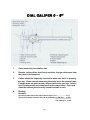
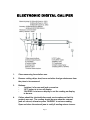
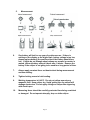
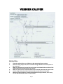
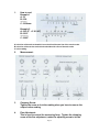
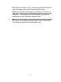
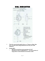
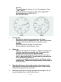
OPERATION INSTRUCTIONS
ALTRACO, INC. OPERATION INSTRUCTIONS
TABLE OF CONTENTS
PAGES 1 – 2
DIAL CALIPER 0-6”
PAGES 3 – 4
ELECTRONIC DIGITAL CALIPER
PAGES 5 – 7
VERNIER CALIPER
PAGES 8 – 9
ELECTRONIC DISC BRAKE CALIPER
PAGES 10 – 11
ELECTRONIC DIGITAL MICROMETER
PAGES 12 – 14
OUTSIDE MICROMETER
PAGES 15 – 16
DIAL INDICATOR
PAGES 17 – 18
6 PC TELESCOPING GAGE SET
PAGES 19 – 20
MAGNETIC BASE
Table of Contents
DIAL CALIPER 0 – 6”
1.
Clean measuring faces before use.
2.
Remove cutting chips, dust, burrs and other foreign substances from
the piece to be measured.
3.
Caliper should be frequently checked to make sure that it is properly
zero set. Clean external measuring faces and close the external jaws.
If needle does not point at zero, caliper needs to be zero set. Loosen
bezel locking screw and rotate bezel at the new position. Open and
close the external jaws to verify if needle returns to zero.
4.
Reading.
Example:
The line on beam and on the left of vernier edge is ‘1.2’…………..……=1.2”
The point of needle is close to line ‘18’ of graduation on dial face…..=0.018”
------------------------------The reading is…1.128”
Page 1
6.
Always apply constant force on thumb wheel during measurement
and zero setting.
7.
Tighten locking screw to hold reading.
8.
Measuring faces should be carefully protected from being scratched
or damaged. Do not operate abruptly, drop or strike caliper.
Page 2
ELECTRONIC DIGITAL CALIPER
1.
Clean measuring faces before use.
2.
Remove cutting chips, dust, burrs and other foreign substances from
the piece to be measured.
3.
Buttons:
‘inch/mm’ is for mm and inch conversion.
‘OFF’ button is to turn off display.
‘ON-ZERO’ is to turn on display or set the reading on display
to be zero.
4.
Caliper should be checked before each use to make sure that it is
properly zero set. The reading should be zero when the external
jaws are closed, otherwise press ‘ON-ZERO’ to set zero reading.
Open and close the external jaws to verify if reading returns to zero.
Page 3
5.
Measurement:
6.
One battery will last for one year of continuous use. If there is
nothing on the display or the digits flash, battery voltage is too low,
please replace battery (the positive side of the battery should face
out). If digits do not change when buttons are pressed or vernier is
moved, take out battery and put it back after 1 minute. Remove the
battery if the caliper is not going to be used for a long period of time.
7.
Always apply constant force on thumb wheel during measurement
and zero setting.
8.
Tighten locking screw to hold reading.
9.
Working temperature is 0-40ºC. Do not put caliper near strong
magnetic field. Keep caliper dry, liquid getting into the caliper will
damage electronics. Do not apply voltage on caliper like engraving
with electric pen.
10.
Measuring faces should be carefully protected from being scratched
or damaged. Do not operate abruptly, drop or strike caliper.
Page 4
VERNIER CALIPER
PRECAUTION:
1.
2.
3.
4.
5.
6.
Clean the caliper before use. Make sure the measuring faces are clean.
Remove cutting chips, dust, burrs and other foreign substances from the piece to
be measured.
Make sure that the zero lines of the vernier scale coincide with the zero lines of the
main scale when the external jaws are closed.
Make sure that no slit is observed between two external jaws when they are closed.
Vernier caliper body should be lubricated with a small amount of clock oil.
Measuring faces should be carefully protected from being scratched, hit or rusty.
Do not operate abruptly, drop or shake caliper.
Page 5
1.
How to read
Example 1
A: 32
B: 0.54
---------C: 32.54mm
Example 2
A: 2.05 (2” + 2 X 1/40”)
B: 0.012
-----------C: 2.062”
A is the line of the main scale which is on the left of the zero line of the vernier scale.
B is the line of the vernier scale which coincides with a line of the main scale.
C is the reading
2.
Measurement:
3.
Clamping Screw:
Tighten the screw to lock the reading when you have to remove the
caliper before reading.
4.
Fine Adjustment:
This is used to control the measuring force. Tighten the clamping
screw of the fine adjustment, rotate the adjusting screw to let the
Page 6
measuring faces be in good contact with the workpiece, meanwhile
the clamping screw must be loose.
5.
Precaution for measurement:
It is important to apply suitable measuring force on the caliper to get
accurate reading. Always use knob of 2310 or the fine adjustment of
2311.
Take care to avoid parallax error when reading the vernier scale.
Parallax error is caused when viewing from A direction. Please view
from B direction.
In order to get smooth sliding, rotate the adjusting screw of the fine
adjustment to make the fine adjustment close to the vernier before sliding.
Page 7
ELECTRONIC DISC BRAKE CALIPER
repair part number:
DRG6059-2
RS232 computer interface cable (optional)
DRG6059-3
fitted case
1.
Clean measuring tip and face before use. Remove cutting chips,
dust, burrs and other foreign substances from the rotor to be
measured.
2.
Buttons:
‘mm/inch’ is for metric and inch reading conversion.
‘ABS’ button is for absolute and relative measuring mode
conversion. The normal mode is absolute measuring mode.
Press ‘ABS’ to enter into relative measuring mode, ‘INC’
appear on display. Press ‘ON ZERO’ button at any point (this
point is called ‘relative zero point’), the reading is zero. In this
mode, the reading at a point is the difference between the
actual value of this point and the value of relative zero point.
Press ‘ABS’ to exit from relative measuring mode and enter
into absolute measuring mode, the reading is absolute value.
Press ‘ABS’ button to enter into relative measuring mode
Page 8
-
again if necessary, the relative zero point is not changed until
‘ON-ZERO’ is pressed to set a new relative zero point.
‘ON ZERO’ is to turn on/off display and set the reading on
display to be zero. Press it to set zero reading. Keep pressing
it for three seconds to turn off display. Display is
automatically turned off in about 5 minutes if gauge is not
used. Press ‘ON-ZERO’ or move vernier to turn display on.
3.
Gage should be checked to make sure that it is properly calibrated
before each use. The reading should be zero when measuring tip
and face are in contact, otherwise press ‘ON-ZERO’ to set zero
reading. Separate and return them to be in contact again to verify if
reading returns to zero.
4.
Take care that gage is perpendicular to the rotor to prevent
measurement error. To assure this, keep the flat measuring face in
full contact.
5.
To measure a rotor in a position where the display cannot be viewed,
press ‘ON-ZERO’ button and remove gage. Move the measuring tip
and face to be in contact and the reading is the actual rotor
thickness with a ‘-‘ in front.
6.
One battery will last for one year of continuous use. If there is
nothing on the display or the digits flash, battery voltage is too,
please replace battery (the positive side of the battery should face
out). If digits do not change when buttons are pressed or vernier is
moved, take out battery and put it back after 1 minute. Remove the
battery if the caliper is not going to be used for a long period of time.
7.
Always apply constant force on thumb wheel during calibration and
measurement.
8.
Tighten locking screw to hold reading.
9.
Working temperature is 32-72ºF. Do not put gage near strong
magnetic field. Keep gage dry, liquid getting into the caliper will
damage electronics. Do not apply voltage on gage like engraving
with electric pen.
10.
Measuring tip and face should be carefully protected from being
scratched or damaged. Do not operate abruptly, drop or strike gage.
Page 9
ELECTRONIC DIGITAL MICROMETER
1.
Keys
Page 10
2.
Specification:
Resolution: 0.001mm / 0.00005”
Accuracy: 0.003mm / 0.00012”
Repeatability: 0.001mm / 0.00005”
Measuring force: 5 – 10n
Power consumption: ≤ 10 µ A
Max. measuring speed: 80mm/s
Operation temperature: 0-40ºC
Date Output: RS232C
3.
Power:
One silver oxide cell SR44W or SR44 for continuous use of
one year.
Display flashes when battery voltage is lower than 1.4V.
Please replace battery.
Power will be automatically turn off in five minutes if
micrometer is not used.
Press mm/in or move spindle to turn on power.
4.
Maintenance:
Calibrate micrometer frequently.
Clean measuring surfaces with soft cloth. Acetone, alcohol
and other volatilization cannot be use.
Do not dissemble or drop the micrometer.
Do not put the micrometer near strong magnetic field.
Keep micrometer clean and dry, liquid getting into the caliper
will damage electronics.
Remove battery if micrometer is not used for a long time.
Page 11
OUTSIDE MICROMETER
1.
Clean the micrometer gently before use. Make sure the measuring
faces are clean.
2.
Remove cutting chips, dust, burrs and other foreign substances from
the piece to be measured.
3.
Standard rod and adjusting wrench:
They are used to calibrate micrometers. Micrometers should be
calibrated frequently. The length of the standard rod is 25mm for
5607 (25-50mm), 50mm for 5608 (50-75mm) and 75mm for 5609 (75100mm). 5606 (0-25mm) doesn’t have standard rod and it can be
regarded as having a standard rod of zero length. The reading must
Page 12
be the same as the length of standard rod when the micrometer
‘measures’ the rod. For example, when 5607 (25-50mm) ‘measures’
its standard rod 25mm, the reading must be 25mm exactly.
Otherwise you should adjust the micrometer. Put the small point of
the adjusting wrench into the small hole on the sleeve which is near
the locking lever, rotate the sleeve to make the zero line of the
thimble align with the horizontal line of the sleeve. Another end of
the adjusting wrench is used to fix or unfix the ratchet stop.
4.
How to measure:
Let the anvil contact with the workpeice first. Rotate the thimble or
the ratchet stop till the spindle is close to (but not in contact with)
the workpeice. Rotate the ratchet stop until you hear a click from the
ratchet stop.
5.
Locking lever:
Tighten this lever to lock the reading when you have to remove the
micrometer before reading.
6.
How to read
Example 1
A: 35
B: 0.12
---------C: 35.12mm
Example 2
A: 42.5
B: 0.148 (8 is estimated)
-----------C: 42.648mm
A is the line of the sleeve which is on the left of the thimble.
B is the point on the thimble which aligns with the horizontal line on sleeve.
C is the reading
The graduation on the sleeve is 0.5mm. One rotation of the thimble makes
0.5mm (1 graduation) step on the sleeve.
7.
Precaution for measurement:
Page 13
Never rotate the thimble to let the spindle contact with the workpeice,
which may damage the precision thread inside the sleeve.
Please grip the heat isolation plate if you hold the micrometer for a
long time, in order to prevent heat transferring from your hand to the
micrometer. If the workpeice and the micrometer are a different
temperature, an error of accuracy may be caused.
8.
Measuring faces should be carefully prevented from being scratched,
hit or rusty. Do not operate abruptly, drop or strike the micrometer.
The spindle should be oiled to avoid getting rusty.
Page 14
DIAL INDICATOR
1.
Clean the measuring tip gently before use. Remove cutting chips,
dust, burrs and other foreign substances from the piece to be
measured.
2.
Reading 5603:
Dial face has dual directional graduation of 0.001”.
Revolution counter is graduated in 0.1”. One full revolution of
large pointer is one increment of revolution counter.
Page 15
Example:
The small pointer is between ‘.1’ and ‘.2’ or between ‘.6’ and
‘.7’=0.1” or 0.6”
The large pointer is close to line ‘21’ of black digit=0.021”
So the reading is 0.1”+0.021”=0.121”
Or 0.6”+0.021”=0.621”
3.
Reading 5604:
Dial face has dual directional graduation of 0.01mm.
Revolution counter is graduated in 1mm. Once full revolution
of large pointer is one increment of revolution counter.
Example:
The small pointer is between ‘1’ and ‘2’=1mm
So the reading is 1mm+0.14mm=1.14mm
4.
Setting up:
5603 has 3/8” diameter shank and ¼” diameter mounting hole,
5604 has 8mm diameter mounting hole. The shank or the
mounting hole can be fixed on magnetic bases.
Position measuring tip against the piece to be measured so
that it is depressed slightly. Plunger should be perpendicular
to the surface being measured.
Loosen bezel locking screw and rotate bezel till large pointer
points at zero. Tighten bezel locking screw to lock the bezel at
its new position.
5.
Move the left tolerance index to the position of lower limit and the
right tolerance index to the position of upper limit, It can be found
easily if the large pointer is our of limit.
6.
Measuring tip should be carefully prevented from being hit. Do not
operate abruptly, drop or strike dial indicators
Page 16
6 PC TELESCOPING GAGE SET
1.
The measuring range of each piece is:
A:
8 - 12.7mm (5/16” – 1/2")
B.
12.7 – 19mm (1/2” – 3/4")
C.
19 – 32mm (3/4” – 1 1/4”)
D.
32 – 54mm (1 1/4” – 2 1/8”)
E.
54 – 90mm (2 1/8” – 3 1/2")
F.
90 – 150mm (3 1/2" – 6”)
2.
This gage measure diameter of a hole or other inside dimensions.
Choose a suitable piece of gage according to the size of dimension
to be measured. Loosen locking screw and let the two plungers
expand inside the dimension. Lock the plungers by tightening the
locking screw and then remove the plungers. Measure the distance
between two contacts with micrometers or calipers to obtain the size
of the dimension.
3.
Clean contact tips before use. Remove cutting chips, burrs and
other foreign substances from the piece to be measured.
Page 17
4.
Measurement:
Page 18
MAGNETIC BASE
1.
Fix all dial indicators with 8mm diameter shank and lug back with
6.3mm or 1/4" diameter mounting hole
Page 19
2.
Attach on flat surface horizontally or vertically, as well as on
cylindrical surface.
3.
Permanent pulling magnet is 60 KGS. Switch is used to turn on or
turn off magnet. Turn off magnet when magnetic bases are not in
use.
4.
Use find adjustment to adjust the position of dial indicator slightly.
5.
Keep all setups as short as possible. Unnecessary length from dial
indicator to the base increase the undesirable possibility of dial
indicator movement.
Page 20