1
OWNER'S MANUAL
Professional Mixing Amplifier
DX-333
Operating Instructions
MIC1
VOL
INPUT
BAL
ECHO
LOW
MID
MIC MASTER VOL
HI
-20dB
8
GAIN
PEAK 0
MIC2
10
10
VOL
INPUT
L5
BAL
R5
0
10
ECHO
-15
LOW
+15 -12
+12 -15
MID
+15
HI
VOL
INPUT
BAL
R5
0
10
ECHO
-15
LOW
+15 -12
+12 -15
MID
9
10
11
13
15
5
15
16
4
16
17
1
+15
0
20
19
3
18
17
2
1
0
20
19
18
R
PEAK 0
10
VOL
L5
R5
LOW
0
HI
10
-15
RPT
+15 -12
+12 -15
DLY
16 BIT DIGITAL KEY CONTROLLER
+15
KEY CONTROL
REMOTE
ST MO
b4
SELECTOR
0
MUSIC
OFF
HI
GAIN
Extra Echo
ON
14
-20dB
ECHO
POWER
12
7
6
14
4
2
L5
8
13
3
10
MUSIC MASTER VOL
12
5
-20dB
PEAK 0
Extra Echo Effect
11
6
GAIN
MIC3
9
7
10
VOL
L5
BAL
R5
0
10
LOW
-15
MID
+15 -12
b3
+12
B
HI
10
L5
R5
0
10
-15
+15 -12
b1
#1
b
#2
#
B
B INPUT
0
b2
+12
DX-333
Thank you for purchasing this unit.
To make full and effective use of this
unit, please read this Owner's
Manual carefully before operating it.
After reading this manual, retain this
booklet together with the Warranty
Card for future use in case of
maintenance or troubleshooting.
EVOLUTION OF KARAOKE
www.bmbkaraoke.com
#3
#4
A
A
LOW
NORMAL
HIGH
A INPUT
walked upon or pinched by items placed upon or
against them. Please pay particular attention to cords
at plugs, convenience receptacles, and the point
where they exit this BMB product.
RISK OF ELECTRIC SHOCK
DO NOT OPEN
CAUTION: TO REDUCE THE RISK OF ELECTRIC SHOCK
DO NOT REMOVE COVER (OR BACK) NO
USER-SERVICEABLE PARTS INSIDE REFER SERVICING
TO QUALIFIED PERSONNEL
11. Object and Liquid Entry: Care should be taken so
that objects do not fall on, or liquids are not spilled
into this BMB product.
12. Damage Requiring Service: This BMB product
should be serviced only by qualified service personnel
when:
A. The power-supply cord or the plug has been
damaged; or
B. Objects have fallen, or liquid has spilled into
this BMB product; or
C. This BMB product has been exposed to rain; or
D. This BMB product does not appear to
operate normally or exhibits a marked change in
performance; or
E. This BMB product has been dropped, or its
chassis damaged.
SAFETY INSTRUCTIONS
1. Read Instructions: All the safety and operation
instructions should be read before this BMB product is
operated.
2. Retain Instructions: The safety and operating
instructions should be kept for future reference.
3. Warnings: All warnings on this BMB product in
these operating instructions should be followed.
4. Follow Instructions: All operating and other
instructions should be followed carefully.
13. Servicing: The user should not attempt to service
this BMB product beyond those means described in
this operating manual. All other servicing should be
referred to the BMB Service Department.
5. Water and Moisture: This BMB product should not
be used near water, for example, near a bathtub,
washbowl, kitchen sink, laundry tub, in a wet
basement, near a swimming pool, swamp or salivating
St. Bernard dog, etc.
14. To prevent electric shock, do not use this
polarized plug with an extension cord, receptacle or
other outlet unless the blades can be fully inserted to
prevent blade exposure.
6. Cleaning: Clean only with a dry cloth.
7. Ventilation: This BMB product should be situated so
that its location or position does not interfere with its
proper ventilation. For example, the Component
should not be situated on a bed, sofa, rug, or similar
surface that may block any ventilation openings, or
placed in a built-in installation such as a bookcase or
cabinet that may impede the flow of air through
ventilation openings.
15. Grounding or Polarization: Precautions should be
taken so that the grounding or polarization means of
this BMB product is not defeated.
16. Power Precaution: Unplug this BMB product
during lightning storms or when unused for long
periods of time. Note that this BMB product is not
completely disconnected from the AC mains service
when the power switch is in the OFF position.
8. Heat: This BMB product should be stay away from
heat sources such as radiators, or other devices
producing heat.
17. This apparatus does not exceed the Class
A/Class B (whichever is applicable) limits for radio
noise emissions from digital apparatus as set out in the
radio interference regulations of the Canadian
Department of Communications.
9. Power Sources: This BMB product should be
connected to a power supply only of the type
described in these operation instructions or as marked
on this BMB product.
18. Exposure to extremely high noise levels may cause
permanent hearing loss. Individuals vary considerably
in susceptibility to noise-induced hearing loss, but
nearly everyone will loss some
hearing if exposed to sufficiently intense noise for a
10. Power Cord Protection: Power supply cords
should be routed so that they are not likely to be
2
period of time. The U.S. Government's Occupational
Safety and Health Administration (OSHA) have
specified the permissible noise level exposures shown
in the following chart.
According to OSHA, any exposure in excess of
these permissible limits could result in some hearing
loss. To ensure against potentially dangerous exposure
to high sound pressure levels, it is recommended that
all persons exposed to equipment capable of
producing high sound pressure levels use hearing
protectors while the equipment is in operation. Ear
plugs or protectors in the ear canals or over the ears
must be worn when operating the equipment in order
to prevent a permanent hearing loss if exposure is in
excess of the limits set forth here.
Accessories
Do not place the set on an unstable cart, stand, tripod,
bracket, or table. The set may fall, causing serious
injury to a child or an adult, and serious damage to
the set. Use only a cart stand tripod, bracket, or table
recommended by the manufacturer.
For the set with a three-wire grounding type ac plug:
This plug will only fit into a grounding-type power
outlet. This is a safety feature. If you are unable to
insert the plug into the outlet, contact your electrician to
have a suitable outlet installed. Do not defeat the
safety purpose of the grounding plug.
AC-Power Sources
This set should be operated only from the type of
power source indicated on the marking label. If you
are not sure of the type of electrical power supplied to
your home, consult your dealer or local power
company. For those sets designed to operate from
battery power, or other sources, refer to the operating
instructions.
110V AC-POWER
Duration Per Day Sound Level dBA,
In Hours
Slow Response
8
90
6
92
4
95
3
97
2
100
1.5
102
1
105
0.5
110
0.25 or less
115
AC-POWER CORD INCLUDED
Typical
Example
Duo in small club
Subway Train
Very loud classical music
Patrice screaming at Ron about deadlines
Loudest parts at a rock concert
WARNING- To reduce the risk of fire or electric shock, do not expose
this appliance to rain or moisture.
Overloading
Do not overload wall outlets, extension cords or
convenience receptacles beyond their capacity, since
this can result in fire or electric shock.
CONTENTS
Introduction................................................. 4~6
Package accessories........................................ 7
Specifications................................................. 7
Speaker connection......................................... 7
Name and functions of remote controller.............. 8
Features and functions of the amplifier............ 9~11
110V AC-POWER
Connector information..................................... 12
Physical........................................................ 12
How to connect speaker..................................13
An appliance and cart combination
should be move with care. Quick
stops, excessive force and uneven
surfaces may cause the appliance
and cart combination to overturn.
How to connect music A.V. source.................... 13
How to connect record................................... 13
How to connect home theater and karaoke......... 14
How to connect microphone............................ 15
3
INTRODUCTION
Thank you for choosing the BMB DX-333 Stereo
Mixing and Digital Key Control Amplifier (also called
BMB DX-333). We appreciate your vote of
confidence in this innovative product. BMB DX-333 is
indeed a hybrid of power amplifier and mixer that can
help you save more space and achieve convenience.
It can produce the lowest level of feedback. It is
designed to fulfil the amplification needs of almost any
type of application. It also boasts some special
features you would expect to pay for - like adjustable
built-in equalizer at different levels (i.e. Hi-EQ,
Mid-EQ, and Low-EQ) enabling the microphone to
adjust music key while you are singing Karaoke,
subwoofer filtering, speaker-protecting limiter, etc.
Perhaps the most important feature of the BMB DX-333
Power Amplifier is the attention to detail in every
aspect of designs.
BMB DX-333 is based on real and proven design
principles. The result of using proven design principles
is a production of a power amplifier that can perform
better than conventional designs when presented with
adverse conditions. The design can also satisfy
multi-uses for home Karaoke, Professional D.J., KTV
rooms and equipment rental.
One of the most difficult things for a power
amplifier to handle is clipping. Conventional designs
use lots of negative feedback to provide stability and
lower distortion. When clipping occurs, this "feedback"
causes high-frequency sticking, keeping the amplifier
"latched" in the clipping state longer than necessary.
This results in painfully audible distortion. The design of
BMB DX-333 can eliminate this high-frequency sticking
and allow the amplifier to remain stable when
powering high reactive loads high volume level.
To operate the BMB DX-333 Stereo Mixing and
Digital Key Control Amplifier properly, please read this
manual carefully and follow the instructions.
SPECIAL FEATURE DESCRIPTIONS
Gain
There are two viewpoints regarding the gain
structure of power amplifiers - constant gain and
constant sensitivity. Constant gain means that
regardless of the output power of the amplifier, the
gain from input to output remains the same. (By the
way, this refers to the full gain of the amplifier, with the
gain or level controls all the way up.) Within a product
line of constant gain power amplifiers, as the output
power rating of an amplifier increases, the level of the
input voltage must also increases. For example, if an
amplifier is rated at 100W into an 8-ohm load, and it
has 26 dB of gain, it requires an input signal of 1.4V
rms to drive it to full power. This is about +5 dBu, a
reasonable operating point for professional gear.
Now take an amplifier rated at 200W into an
8-ohm load. If it also has a gain of 26 dB, it requires
an input signal of 2.0V rms to drive it into full power,
or +8 dBu. This can become problematic as the
power of the amplifier increases. What if you have a
power amp rated at 800W into 8 ohms? This will
require an input signal of 4.0V rms to drive it to full
power. This equates to a whopping +14.3 dBu!
You've just robbed your mixer of 10 dB of headroom.
You'll either have to have a good limiter to keep the
transient peaks down, or turn down the level from the
mixer and not use all the power available from the
amplifier.
Constantly sensitivity means that regardless of the
output power of the amplifier (the input voltage
required to attain full output power) remains the same.
As the output power of an amplifier increases, the gain
of the amplifier must also increase. Referring back to
the previous example, an amplifier rated at 100W
into 8 ohms with a gain of 26 dB requires an input
signal of 1.4V rms to drive it to full power. It has an
input sensitivity of 1.4V rms. In order for the 200W
amplifier to reach full power into 8 ohms with a 1.4V
rms input signal, it must have a gain of 29dB. And the
800W amplifier will require a gain of 35 dB to reach
full power with a 1.4V input signal.
So what are the pros and cons of these two
approaches? The reason some amplifier manufacturers
use the constant gain approach is because the noise
specification looks better It's a fact of physics that as
the gain of the amplifier increases, the circuit noise is
amplified and increases too. By maintaining a
constant gain, the noise spec for an 800W amplifier
can look as good as the noise spec for a 100W
amplifier. The downside to this is that you have to
crank up your mixer level feeding the input of the
amplifier, losing headroom and possibly increasing the
4 noise level from the mixer.
Conversely, constant sensitivity demands that as
the power increases, so must the gain. Yes, the output
noise of the amplifier will increase, but you maintain in
the critical headroom available from your mixer. The
additional noise is generally not a problem in live
sound reinforcement situations. If it is, you can turn
down the GAIN control a few clicks to find a happy
compromise between noise floor and headroom
available. As an added benefit, you can drive multiple
amplifiers with the same signal and get the maximum
power available from all of them.
The BMB DX-333 Stereo Mixing and Digital Key
Control Amplifier has low, mid peaking, and high
built-in equalizer.
The gain structure of the BMB DX-333 Stereo
Mixing and Digital Key Control Amplifier is designed
so that a 4 dBu (1.23V rms) input signal drives the
amplifier to 425 watts into 4 ohms. This is how the
sensitivity of an amplifier is defined. In this case, it
equates to a voltage gain of about 20 dB.
MID-EQ
HI-EQ
This control provides from -15 dB to + 15 dB of
boost of cut, and it is also flat at the detent. Use it to
add sizzle to cymbals or an overall sense of
transparency or edge to keyboards, vocals, guitar,
and bacon frying.
Short for "midrang," it provides from -12 dB to +12
dB of boost or cut, also flat at the center detent.
Midrange EQ is often considered the most dynamic
because the frequencies that define any particular
sound are almost always found in this range.
You can set the GAIN controls as low as you like.
However, reducing GAIN controls requires an
increased input level to reach full power at the
amplifier's output. Like all amplifier controls, you'll
typically determine the optimal settings during
installation or sound check, then leave them alone,
using your signal source to control listening level as
you work.
LOW-EQ
This control provides from -15 dB to + 15 dB of
boost. The circuit is flat (no boost or cut) at the center
detent position. This frequency represents the punch in
bass drums, bass guitar, fat synth patches, and
high-testosterone male singers.
Automatic Zero Volume Adjustment
Smart Fan
The special function of the automatic volume
adjustment automatically sets both of the MIC MASTER
VOL and MUSIC MASTER VOL to zero volume level
when the power is turned on. This would avoid sudden
painfully loud sound to damage hearing power for
ear. You can switch it to for manual operation.
However, we recommend you to use this function to
protect your hearing power.
The fan at the back of the BMB DX-333 Stereo
Mixing and Digital Key Control Amplifier automatically
turns on to cool down the heat when the temperature
reaches 60 degree Fahrenheit.
Music Key Control
Adjustable Built- In Equalizer
You can adjust the music key for Karaoke singing.
Increase the music keys from #1 to #4 and decrease
the music keys from b1 to b4.
5
Echo Effect
Input Wiring
Use a high-quality 3-conductor shielded cable to
connect the signal between the signal source and the
balanced inputs to the amplifier. If you're using the
unbalanced inputs, use a high-quality 2-conductor
shielded cable.
Output Wiring
You can increase the echo effect by adjusting the
volume with Low (Lo) and High (HI) and mixing with
the Time Delay (DLY) and Repeat (RPT).
Use heavy gauge, stranded wire for connecting
speakers to the MA-930 terminals. As the distance
between the amplifier and the speakers increase, the
thickness of the wire should also increase. Speaker
wire has resistance, and when electricity passes
through a resistor, power is lost. The thicker the wire,
the less resistance it offers, and the more power
actually gets to the speakers.
GENERAL CONSIDERATIONS
AC Power Distribution
The majority of AC outlets encountered in homes
and clubs are served by a 240VAC center- tapped
service entrance transformer. This provides two phases
of AC power on either side of the center tap at 120V
each. In order to minimize ground loops, the safety
grounds for all the outlets should be connected to a
common ("star") grounding point, and the distance
between the outlets and the common grounding point
should be as short as possible.
The thickness of wire is rated in gauges. Use the
chart below to determine the correct gauge of wire to
use according to the distance between the speakers
and the amplifier, and the impedance of the load the
amplifier is driving. This ensures that the power lost
across the speaker wire is less than 0.5dB.
If lighting is used in a show, it is preferable to
power the lights from one leg of the service, and
power the audio equipment from the other leg. This
will help minimize noise from the lights coupling into
the audio.
W hen setting up for a show, oftentimes you are
plugging into an AC power distribution system you
know nothing about. You may even be faced with
2-wire AC outlet tester in your toolbox so you can
check the outlets yourself to make sure they are wired
correctly. These testers will tell you if the polarity of the
hot and neutral wires is reversed and if the safety
ground is disconnected. Don't use an outlet if it is
wired improperly! This is to protect yourself as well as
your equipment.
If you find that you must plug into a two-wire outlet,
you will need to use a two-wire to three-wire adapter
(cheater plug). These come with a metal tab that you
put underneath the center screw that holds the AC
outlet faceplate in place. This center screw must be
grounded. You can check it by connecting the adapter
to the outlet and then plugging in your AC outlet tester.
6
WIRE
LENGTH
LOAD
IMPEDANCE
GAUGE OF WIRE
Up to 25 ft
2
4
8
14 gauge
16 gauge
18 gauge
Up to 40 ft
2
4
8
12 gauge
14 gauge
18 gauge
Up to 60 ft
2
4
8
10 gauge
12 gauge
16 gauge
Up to 100 ft
2
4
8
8 gauge
10 gauge
14 gauge
Up to 150 ft
2
4
8
6 gauge
8 gauge
12 gauge
Up to 250 ft
2
4
8
4 gauge
6 gauge
10 gauge
SAFETY PRECAUTIONS
PACKAGE ACCESSORIES
Selecting fine audio equipment such as the unit
you've just purchased is only the first step to your
musical enjoyment. Now it's time to consider how you
can maximize the fun and the safety of your new
equipment. We want you to get the most out of your
equipment by playing it at a safe level without
affecting your hearing. Sound can be very harmful.
Over time your hearing "comfort level" adapts to higher
volumes of sound. What sounds "normal" can actually
be loud and harmful to your hearing. Therefore,
please guard against this by setting your equipment at
a safe level before your hearing adapts. To establish a
safe level, you can start your volume control at a low
setting, then slowly increase the sound until you can
hear it comfortably and clearly. If used wisely, your
new sound equipment will provide you more new
experience in music. Since hearing damage from loud
noise is often undetectable until it is too late, we
recommend you avoid prolonged exposure to
excessive noise. The following noises can be
dangerous under constant exposure. Therefore, please
be cautious with the dB level when playing your new
equipment.
Decible Level
120 dB
140 dB
180 dB
AA
ALKA
L
BATT INE
ERY
AA
ALKA
L
BATT INE
ERY
Battery size: AA (R6 1.5 V)
AC power cable
United States (M) to IEC (F)
Remote control one unit
SPEAKER CONNECTION
TO STEREO SPEAKER
Banana Plug Type
Example
Rock band concert in front of
speakers, thunderclap
Gunshot blast, jet plane
Rocket launching pad
Insert Type
TWO PAIR SPEAKER SYSTEM
SPECIFICATIONS
A Speaker
Left
Audio Output................................. 300W+300W
MIC Input Sensitivity........................ 0<15mV
External Devices Sensitivity............... 250mV
Signal/Noise Ratio (with IHF A Filter)..80dB
T.H.D (1kHz.AUX 150mV INPUT)......2%
Frequency Band............................. 25Hz~20kHz
MIC. Tone Adjustment..................... 80Hz+15dB
3.5kHz+15dB
12kHz+15dB
ECHO Tone Adjustment................... 80Hz+15dB
12kHz+15dB
Power Source................................ AC110V/60Hz
Electricity Consumption.................... 550W
Weight.........................................33LBs
Dimension (inch)............................. 15 (W)x7(H)x17(L)
B Speaker
Left
7
Amplifier
A Speaker
Right
B Speaker
Right
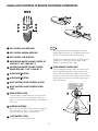
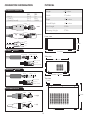
NAMES AND FUNCTIONS OF REMOTE CONTROLLER COMPONENTS
3
2
1
10
R
LOW
NORMAL
b
5
7
9
HIGH
#
A
INPUT
11
4
MIC
MASTER
VOLUME
B
MUSIC VOLUME
ALKA
LI
BATT NE
ERY
AA
6
AA
ALKA
LI
BATT NE
ERY
8
remote controller
12
DX-333
1
NOTE
KEY CONTROL HIGH RESPONSE
2
KEY CONTROL NATURAL RESPONSE
3
KEY CONTROL LOW RESPONSE
4
MICROPHONE MASTER VOLUME CONTROL UP
LEVEL (MIC.1, MIC. 2 AND MIC. 3)
5
MICROPHONE MASTER VOLUME CONTROL
DOWN LEVEL (MIC.1, MIC. 2 AND MIC. 3)
6
AUDIO INPUT B BUTTON
7
AUDIO INPUT A BUTTON
8
MUSIC MASTER VOLUME CONTROL UP LEVEL
Remove the batteries to avoid damage from possible
battery leakage whenever you anticipate that the remote
control will not be used for an extended period.
Handle the remote control with care. Avoid dropping it,
getting it wet, or placing it in direct sunlight, near a
heater, or where the humidity is high.
13
USING REMOTE CONTROL UNIT
When operating the remote control unit, point the unit's
infrared signal transmitter at the remote control remote
sensor on the front panel of the amplifier. The remote
control unit can be used within a range of about 18 feet
(6m) from the remote sensor, and within angles of up to
about 30 degrees.
MIC1
INPUT
MIC2
INPUT
MIC3
INPUT
VOL
BAL
ECHO
LOW
MID
MIC MASTER VOL
HI
-20dB
PEAK 0
10
VOL
L5
BAL
R5
0
10
ECHO
-15
LOW
+15 -12
+12 -15
MID
10
11
8
13
R5
0
10
ECHO
-15
LOW
+15 -12
+12 -15
MID
15
5
16
4
17
10
11
POWER
12
13
15
16
17
2
18
1
20
ON
14
3
19
0
+15
9
7
6
14
18
1
L5
BAL
MUSIC MASTER VOL
12
4
2
10
VOL
OFF
19
0
20
HI
R
-20dB
GAIN
PEAK 0
L5
R5
LOW
0
HI
10
-15
RPT
+15 -12
+12 -15
16 BIT DIGITAL KEY CONTROLLER
+15
DLY
KEY CONTROL
REMOTE
EMO
ST MO
Extra Echo
Extra Echo Effect
10
VOL
ECHO
b4
SELECTOR
MUSIC
0
10
0
10
VOL
L5
BAL
R5
0
10
LOW
-15
MID
+15 -12
b3
R5
0
10
-15
+15 -12
b2
b1
#1
#2
#3
#4
+12
B
HI
b
#
B
A
A
B INPUT
L5
LOW
NORMAL
HIGH
A INPUT
+12
DX-333
OPEN BATTERY COVER
Open the battery compartment cover on the back of the
remote control unit. The cover should open easily if you
press on in with your thumb while sliding it in the direction
of the arrow.
REMOTE
13
18 feet
(6 m)
INSERTING BATTERIES
Insert two size AA (R6) alkaline batteries (supplied)
by matching the + and _ on the batteries to the
diagram inside the battery compartment.
o
30
30 o
R
LOW
NORMAL
b
12
11
5
3
PEAK 0
MUSIC MASTER VOLUME CONTROL DOWN
LEVEL
10
6
+15
HI
-20dB
GAIN
9
9
8
7
GAIN
HIGH
#
MIC
MASTER
VOLUME
CLOSE BATTERY COVER
Close the cover of the battery case.
A
INPUT
B
MUSIC VOLUME
remote controller
DX-333
8
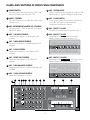
NAMES AND FUNCTIONS OF FRONT PANEL COMPONENTS
1
POWER SWITCH
Press this switch up to turn the power ON. Press
the switch down to turn the power OFF.
10
MIC. 1 SIGNAL LIGHT
When it receives an audio signal at or above 0 dB
automatically on. Signal will appear on the meters.
2
MUSIC. CONTROL
This control allows you to adjust the volume of the
musical source.
11
3
MIC. (MICROPHONE) MASTER VOL. CONTROL
This control MIC.1, MIC.2 and MIC.3 to adjust
the master volume.
MIC. 1 GAIN SWITCH
Turn it on to increase the microphone signal level
to -20 dB. Turn it down to decrease the
microphone signal level to normal.
12
MIC. 1 INPUT 1/4 JACK
This jack is for connecting microphones input 1.
13
MIC. 2 INPUT 1/4 JACK
Same features as MIC.1 with same control
buttons. Please view details from 4 to 12.
4
MIC. 1 (HI) HIGH CONTROL
Adjusts the microphone 1 high frequency EQ
response.
5
MIC. 1 (MID) MIDDLE CONTROL
Adjusts the microphone 1 middle frequency EQ
response.
MIC1
VOL
INPUT
BAL
ECHO
LOW
MID
HI
-20dB
GAIN
PEAK 0
MIC2
10
VOL
INPUT
L5
R5
BAL
0
10
ECHO
-15
+15 -12
LOW
MID
+12 -15
+15
HI
-20dB
GAIN
PEAK 0
6
MIC. 1 LOW CONTROL
Adjusts the microphone 1 low frequency EQ
response.
MIC3
10
VOL
INPUT
L5
R5
BAL
0
10
ECHO
-15
+15 -12
LOW
MID
+12 -15
+15
HI
-20dB
GAIN
PEAK 0
7
MIC. 1 ECHO VOL CONTROL
Adjusts the microphone 1 echo effect EQ
response.
8
MIC. 1 (BAL) BALANCE CONTROL
Adjusts the microphone 1 signal for left and right
speakers.
14
10
L5
R5
0
10
-15
+15 -12
+12 -15
+15
MIC. 3 INPUT 1/4 JACKS
Same features as MIC.1 and 2 with same control
buttons. Please view details from 4 to 12.
MIC1
VOL
INPUT
BAL
ECHO
LOW
MID
HI
-20dB
GAIN
PEAK 0
MIC2
10
VOL
INPUT
L5
R5
BAL
0
10
ECHO
-15
+15 -12
LOW
MID
+12 -15
+15
HI
-20dB
GAIN
9
PEAK 0
MIC. 1 (VOL) VOLUME CONTROL
Adjusts the microphone 1 volume.
14
13
12
MIC1
11 10 9
8
VOL
INPUT
BAL
MIC3
PEAK 0
7
6
ECHO
LOW
5
4
MID
MIC2
VOL
INPUT
BAL
0
MIC3
9
10
11
10
ECHO
-15
LOW
+15 -12
+12 -15
MID
+15
HI
8
13
VOL
INPUT
BAL
10
ECHO
-15
LOW
+15 -12
+12 -15
MID
0
10
+15 -12
MID
9
10
11
13
ON
14
5
15
4
16
17
3
18
+15
+15 -12
POWER
12
7
16
17
2
19
0
-15
1
15
1
0
R5
4
2
R5
L5
6
14
3
L5
-15
LOW
5
-20dB
10
10
MUSIC MASTER VOL
12
6
GAIN
PEAK 0
0
ECHO
2
MIC MASTER VOL
HI
GAIN
R5
10
3
8
L5
R5
18
1
20
OFF
19
0
20
HI
R
-20dB
GAIN
PEAK 0
L5
R5
LOW
0
HI
10
-15
RPT
+15 -12
+12 -15
16 BIT DIGITAL KEY CONTROLLER
+15
DLY
KEY CONTROL
REMOTE
ST MO
Extra Echo
Extra Echo Effect
10
VOL
ECHO
b4
SELECTOR
0
MUSIC
10
VOL
L5
BAL
R5
0
10
LOW
-15
MID
+15 -12
b3
10
L5
R5
0
10
-15
B
HI
+15 -12
b2
b1
#1
#2
#3
#4
+12
b
#
B
B INPUT
0
+12 -15
+15
HI
-20dB
7
10
L5
BAL
GAIN
-20dB
PEAK 0
10
VOL
INPUT
+12
DX-333
9
A
A
LOW
NORMAL
HIGH
A INPUT
+12 -15
+15
NAMES AND FUNCTIONS OF FRONT PANEL COMPONENTS
MIC1
VOL
INPUT
BAL
ECHO
LOW
MID
MIC MASTER VOL
HI
-20dB
8
GAIN
PEAK 0
MIC2
10
VOL
INPUT
L5
BAL
R5
0
10
ECHO
-15
LOW
+15 -12
+12 -15
10
MID
HI
VOL
INPUT
BAL
R5
0
10
ECHO
-15
LOW
+15 -12
+12 -15
MID
9
10
11
13
15
5
15
16
4
16
17
1
+15
0
20
19
3
18
17
2
1
0
20
19
18
R
PEAK 0
10
VOL
L5
R5
LOW
0
HI
10
-15
RPT
+15 -12
+12 -15
16 BIT DIGITAL KEY CONTROLLER
+15
DLY
KEY CONTROL
REMOTE
ST MO
b4
SELECTOR
0
10
VOL
MUSIC
OFF
HI
GAIN
Extra Echo
ON
14
-20dB
ECHO
POWER
12
7
6
14
4
2
L5
8
13
3
10
MUSIC MASTER VOL
12
5
-20dB
PEAK 0
Extra Echo Effect
11
6
+15
GAIN
MIC3
9
7
L5
BAL
R5
0
10
LOW
-15
MID
+15 -12
b3
+12
B
HI
10
L5
R5
0
10
-15
+15 -12
b1
#1
b
#2
#
#3
#4
A
B
A
B INPUT
0
b2
LOW
NORMAL
HIGH
A INPUT
+12
DX-333
29
28 27 26 25 24 23 22 21 20 19
18
INPUT SELECTION
This button is input A selector for input audio signal.
15 A
16
KEY CONTROL
Set the desired key by the 16 bit digital key
controller buttons that have nine steps with signal
light display on top.
17
16
15
23
ECHO (HI) HIGH BUTTON
Adjusts the microphone vocal high frequency EQ
response.
24
MUSIC LOW BUTTON
Adjusts the music low frequency EQ response.
25
ECHO LOW BUTTON
Adjusts the microphone vocal low frequency EQ
response.
INPUT SELECTION
This button is input B selector for input audio signal.
17 B
18
REMOTE SENSOR
The remote control unit can be used within a range
of about 18 feet.
26
MUSIC (BAL) BALANCE BUTTON
Adjusts the music balance signal for left and right
speakers.
19
ECHO (DLY) DELAY BUTTON
Adjusts the delay time with this EQ control. Delay
time is for microphone vocal.
27
ECHO VOLUME BUTTON
Adjusts the echo volume level.
28
MUSIC VOLUME BUTTON
Adjusts the music volume level.
29
ECHO SELECTOR
Adjusts the echo stereo or mono.
20
MUSIC (HI) HIGH BUTTON
Adjusts the music high frequency EQ response.
21
ECHO (RPT) REPEAT BUTTON
Adjusts the interval of repetitions with this EQ
control.
22
MUSIC (MID) MIDDLE BUTTON
Adjusts the music middle frequency EQ response.
10
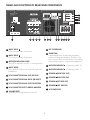
NAMES AND FUNCTIONS OF REAR PANEL COMPONENTS
REAR MIC INPUT
MODEL NO. DX-333
DIGITAL STEREO MIXING
PROFESSIONAL AMPLIFIER
AC-POWER: 110V 60Hz
VOLUME
CONTROLLER
REST
R
BMB
CALIFORNIA, UNITED STATES OF AMERICA
BETTER MUSIC BUILDER TRADEMARK ALL RIGHTS RESERVED
ENGINEERED AND DESIGN IN U.S.A.
KEY ON OFF
Fan turns on automatically when
O
the temperature reaches 60 F
3
2838-83458-3
0
MARK
020898-11
A
14
B
B
15
LOW
16
HIGH
SAFETY
ITEM NO. D030906
MUSIC INPUT
A
SIGNAL SEND
SPEAKER OUT TERMINAL
MUSIC MODE
USA 020898-11
DISCO
HALL
17
AC POWER
OUTPUT
110V 60Hz
L
PRE
R
LINE REC INPUT OUT
31
14
30
29
28
27
MUSIC INPUT A
RCA connector audio source input.
15
MUSIC INPUT B
RCA connector audio source input.
16
MICROPHONE SIGNAL SEND
This is RCA connector out to PC or scoring function.
17
18
26
MUSIC MODE
Disco position for disco use, and Hi-Fi position for
Karaoke use.
25
RCA CONNECTOR SIGNAL INPUT (PRE INPUT)
20
RCA CONNECTOR SIGNAL OUT FOR RECORD
21
RCA CONNECTOR OUT TO BRIDGE AMPLIFIER
22
VOLUME RESET
Automatic volume adjustment to zero level.
11
23 22
21 20 19 18
23
KEY CONTROLLER
24
SMART FAN
It automatically turns on when the temperature
reaches 60 degrees Fahrenheit. Therefore, if the
fan is not on, it does not mean that it is not working.
It has a built-in sensor to measure the temperature.
25
MICROPHONE INPUT
B
(Connecting to MIC. 2)
26
MICROPHONE INPUT
A
(Connecting to MIC. 1)
27
A (RIGHT SIDE OUT)
SPEAKER A
28
SPEAKER BB (RIGHT SIDE OUT)
29
A (LEFT SIDE OUT)
SPEAKER A
30
SPEAKER BB (LEFT SIDE OUT)
31
AC-POWER PLUG
RCA CONNECTOR SIGNAL OUT (PRE OUT)
19
24
CONNECTOR INFORMATION
PHYSICAL
BALANCE XLR CONNECTORS
XLR
Pin 2
Pin 3
Pin 1
Hot (+)
Cold (-)
Shield (Ground)
TRS
Tip
Ring
Shield
2
SHIELD
HOT
MALE
COLD
3
1
3
Height
6 4 inches
Width
17 inches
Depth
13 4 inches
Overall Depth
15 2 inches
Net Weight
33 LBs
Shipping Weight
37 LBs
1
1
SHIELD 1
FEMALE
COLD 3
HOT
SHID
1
3
1
4
H. 7 inches
COLD
2
BALANCE
Front view
2
HOT
TRS PLUG
L. 17 inches
RING SLEEVE
SLEEVE RING TIP
Side view
1
D. 13 4 inches
TIP
RING (COLD)
TIP (HOT)
SLEEVE (SHIELD)
UNBALANCE
1
4
TRS PLUG
SLEEVE
SLEEVE
TIP
1
Overall D. 15 2 inches
TIP
Top view
RING (COLD)
1 1 inches
TIP (HOT)
4
SLEEVE (SHIELD)
RCA UNBALANCE JACK
SLEEVE
SLEEVE
1
15 2 inches
R (right)
TIP
TIP
SLEEVE
SLEEVE
L (left)
TIP
TIP
1 inches
12
HOW TO CONNECT SPEAKER
DIAGRAM 1
A SPEAKER LEFT
A SPEAKER RIGHT
SPEAKER OUT TERMINAL
REAR MIC INPUT
MODEL NO. DX-333
R
DIGITAL STEREO MIXING
PROFESSIONAL AMPLIFIER
AC-POWER: 110V 60Hz
BMB
CALIFORNIA, UNITED STATES OF AMERICA
BETTER MUSIC BUILDER TRADEMARK ALL RIGHTS RESERVED
ENGINEERED AND DESIGN IN U.S.A.
Fan turns on automatically when
O
the temperature reaches 60 F
3
2838-83458-3
VOLUME
REST
KEY ON OFF
F
MUSIC INPUT
A
A
B
B
HIGH
HIGH
0
LOW
L
OW
OW
SIGNAL SEND
SPEAKER OUT TERMINAL
SAFETY
MARK
ITEM NO. D030906
020898-11
USA 020898-11
MUSIC MODE
DISCO
HALL
AC POWER
OUTPUT
110V 60Hz
L
PRE
R
LINE REC INPUT OUT
L
R
B SPEAKER LEFT
B SPEAKER RIGHT
HOW TO CONNECT MUSIC A.V. SOURCE
DIAGRAM 2
stereo audio to music input A
video out to input 1
POWER
MUSIC INPUT
to PC or scoring effect
A
A
B
B
HIGH
LD PLAYER
VIDEO MONITOR
TV
LOW
SIGNAL SEND
REAR MIC INPUT
MODEL NO. DX-333
R
DIGITAL STEREO MIXING
PROFESSIONAL AMPLIFIER
AC-POWER: 110V 60Hz
BMB
CALIFORNIA, UNITED STATES OF AMERICA
BETTER MUSIC BUILDER TRADEMARK ALL RIGHTS RESERVED
ENGINEERED AND DESIGN IN U.S.A.
Fan turns on automatically when
O
the temperature reaches 60 F
3
2838-83458-3
VOLUME
E
REST
KEY ON OFF
F
MUSIC INPUT
A
B
B
HIGH
HIGH
0
MUSIC MODE
CONTROLLER
A
DISCO
HALL
LOW
L
OW
OW
SIGNAL SEND
SPEAKER OUT TERMINAL
SAFETY
MARK
ITEM NO. D030906
020898-11
DISCO
MUSIC MODE
USA 020898-11
HALL
AC POWER
OUTPUT
110V 60Hz
L
PRE
POWER
R
LINE REC INPUT OUT
DVD PLAYER
video out to input 2
stereo audio to music input B
HOW TO CONNECT RECORDER
DIAGRAM 3
REAR MIC INPUT
MODEL NO. DX-333
DIGITAL STEREO MIXING
PROFESSIONAL AMPLIFIER
AC-POWER: 110V 60Hz
R
BMB
CALIFORNIA, UNITED STATES OF AMERICA
BETTER MUSIC BUILDER TRADEMARK ALL RIGHTS RESERVED
ENGINEERED AND DESIGN IN U.S.A.
Fan turns on automatically when
O
the temperature reaches 60 F
3
2838-83458-3
VOLUME
E
REST
KEY ON OFF
F
MUSIC INPUT
A
B
HIGH
HIGH
0
CONTROLLER
A
B
OUTPUT
EQ
PRE
LOW
L
OW
OW
SIGNAL SEND
SAFETY
MARK
ITEM NO. D030906
020898-11
SPEAKER OUT TERMINAL
USA 020898-11
MUSIC MODE
DISCO
HALL
AC POWER
OUTPUT
110V 60Hz
L
PRE
TYPE RECORDER
R
LINE REC INPUT OUT
LINE REC INPUT OUT
POWER AMPLIFIER
13
POWER
HOW TO CONNECT HOME THEATER AND KARAOKE
VIDEO MONITOR
TV
FRONT CHANNEL SPEAKERS
video out to monitor TV
FRONT
LEFT
FRONT
RIGHT
CENTER CHANNEL
POWER
DVD PLAYER
digital audio out
MAIN OUT
SUBWOOFER
SUB
L
FRONT
LEFT
CENTER
CHANNEL
FRONT
RIGHT
SUPR.
LEFT
SUPR.
RIGHT
R
L
R
DTS. THX. RECEIVER
SURROUND
LEFT
SURROUND
RIGHT
SURROUND SPEAKERS
SUBWOOFER
MUSIC INPUT
REAR MIC INPUT
MODEL NO. DX-333
DIGITAL STEREO MIXING
PROFESSIONAL AMPLIFIER
AC-POWER: 110V 60Hz
R
BMB
CALIFORNIA, UNITED STATES OF AMERICA
BETTER MUSIC BUILDER TRADEMARK ALL RIGHTS RESERVED
ENGINEERED AND DESIGN IN U.S.A.
Fan turns on automatically when
the temperature reaches 60 F
VOLUME
E
REST
KEY ON OFF
F
MUSIC INPUT
A
CONTROLLE
A
B
A
A
B
B
B
O
3
2838-83458-3
H IG H
HIGH
0
LOW
L
OW
OW
SIGNAL SEND
SAFETY
MARK
ITEM NO. D030906
020898-11
SPEAKER OUT TERMINAL
USA 020898-11
MUSIC MODE
DISCO
HALL
AC POWER
OUTPUT
110V 60Hz
L
HIGH
HIGH
PRE
R
LOW
LOW
OW
LINE REC INPUT OUT
SIGNAL SEND
MUSIC MODE
DISCO
HALL
NOTE
1. When you play the home theater, you must turn off
power of karaoke amplifier.
2. When you play karaoke from your DVD player, you must
turn down the A.V. (DTS, or THX) receiver's volume to zero.
14
HOW TO CONNECT MICROPHONE
DIAGRAM 4
REAR MIC INPUT
WIRELESS RECEIVER
connect to wireless microphone receiver (MIC. 2)
connect to wireless microphone receiver (MIC. 1)
REAR MIC INPUT
MODEL NO. DX-333
DIGITAL STEREO MIXING
PROFESSIONAL AMPLIFIER
AC-POWER: 110V 60Hz
R
BMB
CALIFORNIA, UNITED STATES OF AMERICA
BETTER MUSIC BUILDER TRADEMARK ALL RIGHTS RESERVED
ENGINEERED AND DESIGN IN U.S.A.
Fan turns on automatically when
the temperature reaches 60 F
VOLUME
REST
KEY ON OFF
F
MUSIC INPUT
A
A
B
B
O
3
2838-83458-3
H IG H
HIGH
0
LOW
L
OW
OW
SIGNAL SEND
SAFETY
MARK
ITEM NO. D030906
020898-11
SPEAKER OUT TERMINAL
USA 020898-11
MUSIC MODE
DISCO
HALL
AC POWER
OUTPUT
110V 60Hz
L
PRE
R
LINE REC INPUT OUT
AMPLIFIER REAR VIEW
AMPLIFIER FRONT VIEW
MIC1
INPUT
MIC2
INPUT
MIC3
INPUT
VOL
BAL
ECHO
LOW
MID
MIC MASTER VOL
HI
-20dB
8
9
10
11
PEAK 0
10
VOL
L5
BAL
R5
0
10
ECHO
-15
LOW
+15 -12
+12 -15
MID
+15
HI
8
13
6
R5
0
10
ECHO
-15
LOW
+15 -12
+12 -15
MID
5
16
4
10
11
POWER
12
13
15
16
17
18
1
20
ON
14
2
19
0
+15
9
3
18
1
L5
BAL
15
17
2
10
VOL
7
4
3
PEAK 0
6
14
5
-20dB
GAIN
MUSIC MASTER VOL
12
7
GAIN
OFF
19
0
20
HI
R
-20dB
GAIN
PEAK 0
ECHO
L5
R5
LOW
0
HI
10
-15
RPT
+15 -12
+12 -15
16 BIT DIGITAL KEY CONTROLLER
+15
DLY
KEY CONTROL
REMOTE
EMOT
ST MO
Extra
E
xtra Echo
Extra Echo Effect
10
VOL
b4
SELECTOR
MUSIC
0
10
0
10
VOL
L5
BAL
R5
0
10
LOW
-15
MID
+15 -12
b3
R5
0
10
-15
+15 -12
b2
b1
#1
#2
#3
#4
+12
B
HI
b
#
B
B INPUT
L5
A
A
LOW
W
NORMAL
RM
HIGH
A INPUT
+12
DX-333
MIC. 1
MIC1
VOL
INPUT
BAL
ECHO
LOW
MID
HI
-20dB
GAIN
PEAK 0
MIC2
10
VOL
INPUT
L5
BAL
R5
0
10
ECHO
-15
LOW
+15 -12
MID
+12 -15
+15
HI
-20dB
GAIN
PEAK 0
MIC3
MIC. 2
10
VOL
INPUT
L5
BAL
R5
0
10
ECHO
-15
LOW
+15 -12
MID
+12 -15
+15
HI
-20dB
GAIN
PEAK 0
10
L5
R5
0
10
-15
AMPLIFIER FRONT PANEL
MIC. 3
15
+15 -12
+12 -15
+15
Printed on 100% Recycled Paper
©2005 Better Music Builder
Comments E-mail to [email protected]
USA All Right Reserved.