1
VISTA
5V40XM
COMMERCIAL FIRE AND
BURGURY AWRM SYSTEM
INSTALWTION
INSTRUCTIONS
NW19V1W3
CONGMTUMTIONS!
On Your Purchase Of The Ademco 5140XM
The purpose of these Installation Instructions is to give you a comple~e
overview of the system, and provide instructions for installing a basic
system.
CONTACTING
TECHNICAL SUPPORT
PLEASE,
Before you can Technical Support, be sure yew.
READ THE INSTRUCTIONS!
● Check au wiring connections.
● Determine
that the power supply anWor backup battery are
supplying proper voltages.
● Veri@
your programming information where applicable.
● Note
the proper model number of this product, and the
version level (if known) along with any documentation that
came with the product.
● Note
your ADEMCO customer number andor company
name.
Having this information handy win make it easier for us to seti
you quictiy and effectively.
●
You may contact Technical Support ti,a Toll Free Fax. Please include your
return fax number. You will receive a reply within 24 hours. You may also
contact Technical Support via modem to ATLIS-BBS, Tech Support’s
Electronic Bulletin Board System. Replies are posted within 24 hours.
East Coast Technical Support: 1-800-645-7492 (8 a.m.-6 p.m. E. S. T.)
West Coast Technical Support: 1-800-458-9469 (8 a.m.-5 p.m. p.S.T.)
Technical Support Fax Number: 1-800-447-5086
ATLIS-BBS Electronic Bulletin Board System: 1-516-496-3980
(1200 -9600 Baud, 8 Data Bik, 1 StatiStop Bit, No Parity)
-2-
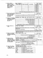
TABLE
GENERAL
INFORMATION . . . . . . . . . . . . . . . . ...5
The 5140XM Control .........................................5
Easy Prqrammim ......... ........ ..... .. .............. ....5
Merno~;f Aarm.~ .......... ....... ...... .. .............. ....5
Buift-in User’s Manual& Dexriptor Review.,.. .... ...5
Il.
ZONE CONFIGURATIONS
. . . . . . . . . . . . . . . . ...6
ZONE WPEDEFINlm~S
...... ....... ............... ....6
BAsfc8HARD-wlRED zoNEs .. ..... .. .............. ...8
Zones 1 a 2: 2-W!re Smoke Detedors ............... 8
fine 6: Alternate Tampar Funtiion ................... 9
Zrme7Alternate
Keyswitch Fundhn ...............9
Zone 8: 2-Wire Glaaa Bre* Detedors .... ... .... ... 9
2-WIRE POLLING LOOP EXPANSION ................1O
Advimries .. ..... ........ .. ..... .. ....... ............... ...l O
Polfing LW Smoke Dettiom ....... .. ........... ...l O
Msc. Polling Loop Devices ............................ll
SYSTEM ZONES ......... .. ....... ........ .............. ...12
Ill.
Iv.
v.
.,-
OF CONTENTS
1.
PERIPHERAL
DEVICES . . . .. . .. .. .. . .. . .. ...13
REmmmNmLEs
...... ....... ......... ............ ...l3
Two Console p0~5 .......................................l3
PowetiW Ati Wring ..... ....... ....... .............. ...l4
Addressable ~nsole DIP Switches .... .. ..........14
BELL CIRCUIT OUTPUTS .................................16
Ganerd lnfomation ........ ..... ......... ............ ...l6
Power and Wiring.., ......... .............................l6
AUXILIARY RELAY .........................................l7
DIALER OUTPUTS ..........................................l8
~&ERO~WS
....... .... .. ..... .. ............... ....l9
General lnformatbn .... .. ..... ....... ............... ....l9
Remtie &nsole Sunder Opration ................2O
Remote Keyswfich @ratbnNiring.
... ........ ...21
5140LED indeator Mule ... ....... .. ............. ...22
Auxitia~ Alarm S@nafing Equipment .....23
. ........23
Event L~ging Ptinter ~nn~ions
.. ........... ....24
Dir@Wrre Downbti~
.... .. ....... .............. ....25
MOUNTING & POWERING . . . . . . . . . . . . . . . ...26
tiuming the Cti!net ........ ....... .............. ......26
Mounting the CaMnet &k . ....... .......... .... ......26
Mounting thetinmles
.... .. ....... ......... ...........27
AdjuSi~the LCD Viewi~ Awle.., ...... .. .. .......28
POWERING THE SYSTEM, . ..... .. ....... ............ ...29
AC Power .. .................................................29
Eatih Ground @nnedbns ..... ....... ............. ...29
Batte~ Supervisbn ...... ..... .. ..... ................ ...3O
Back-Up Pwer Calculations ..........................so
Power-Up Pmdure ... ....... ...... ............... .....3O
Polhng Lwp Cument Draw Worksheet .......... ....31
Total Standby/Alarm bad Worksheets ........ ....31
Battmy Capacity Calculation Worksheet ... .... ...32
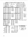
Battery Seltibn
Table ..... ....... .. .............. ....32
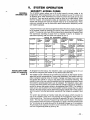
SYSTEM
OPERATION . . . . . . . . . . . . . . . . . . . . ...33
SECURIWACCESS CODES . ....... ................ ....33
Installer Code . ....... ....... ....... .. ........... .... ......33
MasterManager Qdes ... ....... ....... ..... .. .. ... ...35
Opera!or tides . .. ....... ........ ........ ............. ...35
Duress We . .... ......... ....... ...... .. .............. ...35
KEYPAD Functions
.... .. ..... .. ..... .. .............. ...36
Arming Funtiions ....... ......... ..... .............. .....36
Wew Capabi~iies OfaUser ... ........ ............. ....37
WeWing Dow”loaded Messages ......................37
Using the Buift-in User,s Guide...,,,37 ........... ....37
Displaying Descriptors ...... .. ..... .. .............. ....37
Panic Keys ..... ....... ........ ......... .............. .....37
v:
SYSTEM-OPERATION
(cent.)............,,38
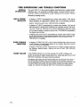
FIRE SUPERVISORY .&TROUBLE CONDITDNS..38
Supewiw~ & ‘Che&” Message ..,., .... ........ ...38
Power F*lure ... ..... ... .... .... ..... .... ... .. ......... ...38
~her Troubie &ndfiions . .... ..... ... ...... ........ ...38
S~lNGTHE
REAL-TiME CLOCK ..... ...... .. .......39
EVENT L~lNG
PROCEDURES . .... ....... ....... ..4O
Pr~rammirrg .... .... ... .... ..... .... .... .... ... ....... ...40
Display& Ptint M&es . .... ... ...... ... ....... ....... ...4O
Clear Event Log . .... .... ... ..... .... .... ..... .. .. ..... ...4l
V1.
SVSTEM
COMMUNICATION
. . . . . . . . . . . . . ...42
Splk/Dual Repoming .....................................42
Adem Low Spe4 . ... .... ... ..... .... .. ......... ......42
SESCOA/Radionics ... .. .. .... ..........................42
4+2 Rap fiing .............................. ...............42
*2 Expre= . .... .... .... ... ..... .... .... ......... ..... ...42
Ademm High Speed Repoting .......................43
tinw
ID Re~tiiW ... ... ..... .... ... ....... ..... .. ...43
Table of Contact ID Event tides ....................44
timmunimtbn
Pr~ramming Guide ................44
V1l.
PROGRAMMING
THE SYSTEM . . . . . . . . . ...45
GENERAL PR~RAMMING
P-EDURES
.... ....45
~mmunhfon
Defauk Pr~ramming..,, ..... .....45
Zone, Devtia
Afpha Prqrmming
... .....45. .....45
P~ramming Steps . . .... .. ..... ... ...... ......... ......45
QMMUNCATfON PROGRAMMING .... ........ ......47
Loading Defaults . ..... .... ...............................47
E=y-to-Pr~rm
Communkation fields ... .. .....47
Summary of Defaufr tins~uences
... ...... .. .....48
PRffiWMING
DATA FIELDS . .... ..... ...... .. ......49
*MmuwE
...... ... .. .... ... .. .. ..... ......... .......5o
ZOne P~ramming ... .... ... ...... . .. .... ........ .......50
Device Programming ....................................5o
Al~a PqrammiW
. .. ... ... ..... .... .... .. ........ .....5l
Enteting Zone Dexriptors . .... ..... ..... .. ....... ....5l
Adding Custom Words . .................................52
Creating a Custom Message ..........................52
Vocabulary of Wordsln MemoV .....................53
Vlll.
lx.
x.
——
——
——
xl.
——
DOWNLOADING
PRIMER . . . . . . . . . . . . . . ...54
TESTING THE SYSTEM . . . . . . . . . . . . . . . . . ...56
Batte~ Test . .............. ...................... ..........56
Daler Test ... ... .... ... .... .... .... ..... ..... ....... .......56
Ere Drill T& ... .... ... .... .... ... .... ..... ......... .......56
One Man Fire Walk Test ................................56
Burglary Wafk Tast .. ... ... .... .. ... .... ....... ....... ...57
Arm.WBugla~ Tea ... ... .... .... ..... ..... .. ....... ...57
Turning the System Over to the User,, ........57...57
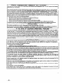
REGULATORY
AGENCY REQUlREMENT!j58
Wsc. ULR~uirments . ... .... ..... ... .... ......... ..... ...58
New York C~R~uirements
.... .... .... ........ ..... ...58
4190WH
OPERATION
& WIRING .... ......59
DIP SWITCH
SETTING
TABLEs .... .... ...6o
COMMUNICATION
DEFAULTS .. . ... .. .. ...62
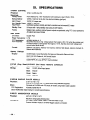
SPECIFICATION
S . . . . . . . . . . . . . . . . . . . . . . . . . . . 66
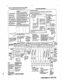
SUMMARY OF CONNECTIONS . . . . . . . . . ...67
PROGRAMMING
FORM . . . . . . . . . .. Centerfold
--3-
LIST OF FIGURES
LIST OF FIGURES
1,
5140XM FIRE CONTROL SYSTEM .....................................................................................5
2.
ALARM SAF POWER SUPPLY CONNECTION DIAGRAM ...................................................l4
3.
ADDRESSABLE CONSOLE .............................................................................................l5
4.
BELL clRculT wlRING .....................................................................................................l6
5.
AUXILIARY REMY wlRING ...............................................................................................l7
6.
J2 PIN ASSIGNMENTS AND Functions
7.
REMOTE CONSOLE SOUNDER WIRING ..........................................................................2O
_
..........................................................................l9
8.
KEYswlTcH wlRING ........................................................................................................2l
9,
5140LED INDICATOR MODULE WIRING ...........................................................................22
10.
7620ULF’& 7920SE WIRING DIAGRAM .............................................................................23
11.
346 POLARITY REVERSING RELAY WIRING .....................................................................23
12.
W HIGH LINE SECURITY DIRECT WIRE TRANSMl~ER WIRING ......................................23
13.
EVENT LOGGING PRINTER Connections
14.
DIRECT WIRE DOWNLOADING Connections
15.
CABINET ATTACK RESISTANCE CONSIDERATIONS .......................................................26
16.
SURFACE MOUNTING CONSOLES ..................................................................................27
17.
FLUSH MOUNTING CONSOLES .......................................................................................28
18.
ADJUSTING THE VIEW ANGLE .........................................................................................28
19.
BATTERY CONNECTION DIAGRAM ..................................................................................29
20.
4190WH WIRING DIAGRAM ..............................................................................................59
21.
SUMMARY OF CONNECTIONS DIAGRAM .........................................................................67
.....................................................................24
................................................................25
-
-4-
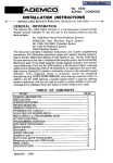
GENERAL
INFORMATION
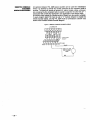
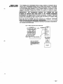
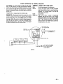
THE 5140XM
CONTROL
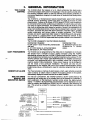
The 5140XM offers the features of a UL listed commercial fire alarm alnd a
commercial h~ia~
ala~ pSnel in one package. It may be used to provide either
fire warni~ protection alone or both fire warning and burglay protection in
commercial ~~mbns
ranging from small stores to ~erate
sized facfory/clffice
complexes.
The 5140XM is a microprocessor based programmable panel which features
EEROM memory technobgy (power loss does not result in the loss of panel
programming). R albws up to s’~een 5137AD (gray)/5137ADR (red) consoles to
be mnnecfed whwh provkfe audible~sual indications of system status and :illow
user errf~ of system @mmaMs. The5140XM provties 8 class B (style B) zones
ati a buih-in polhng bop w~ch albWS the number of zones to ~ expanded to 64
using 2-wire Plfing loop devbs.
Zones maybe programmed to provide mainual
fire alarm, automati fire alarm wth alarm verification, waferfbw alarm, sprinkler
system supervisory and various types of burgla~ protection. The 5140XM
provides one hiff-in auparviaed dialer output for transmitting alarm and sytiem
status reprts to a Mnfral station via the swtichad telephone nefwok. It also
allows an optional5140DLM supervised back-up dialer module to be conneded i
required.
The 5140XM is designed to meet the foltiing
standards:
Commercial
Burglary:
Commercial
Fire:
UL6W Grade A bcal mercantile premise~safe
UL 884/NPFA 72A local and
ati vauk
UL864/NFPA
71 central
UL 611/1610 Grades A, AA Central Statin
afatirr
UL 3* Grades A, AA Po~ie tinnaof
EASY PROGRAMMING
The 5140XM can be programm~ at the office prior to installation or on the job
site directly from a console or from a laptop wmputer using the 4130PC
downbading software and the4100SM PC/panel serial interface module. It can
alw be programmed remtely over the swtichsd telephone wires using a PC, the
4130PC software and a Hayes 1200 SMARTMODEM. For installer mnvenience,
the panel is pre-programmed with a set of standard values that is designf!d to
meet the needs of many installations. These values, however, can be changed to
sun the needs of any patiicular installation. The panel can also be preprogrammed by the installer with one of four standard communication defauk
programming values, etiminafing the need for extensive programming time and
effort.
-
IMEMORY-OF-ALARM
The Panel provides a memo~-of-alarm feature, whch, upon entering a securtiy
wde to ‘silence an alarm andor to dbarm the burglary potion of the system,
aufomatilly diaphya an zones that were in an alarm corrdiinn.
BUILT-!N USER’S
MMUAL
AND
DESCRIPTOR REWW
For end-user Wnveniewe, the 5140XM wntains a built-in Users Manual. By
depressing and froting any of the furrcfbn keys on the console for 5 semnds, a
brief exDlanafion of that Darficular function Wrolls across the aloha-numeric
di~lay.’ In atifon,
all p~rammad
zone descriptors can be displa~ed (one at a
time) by pressing and holding the READY key for 5 seconds, then releasing the
key. This serves as a check for installers to be sure all descriptors are entered
properly.
I
8-
5,,,-,,m.
m.=,
(2wPPom2.W(RE
SMOKE
.mc,o.s)
I
I
N,Ofi,c.
BURGMY
b BEu, m
PRmwwE
Plw)
q. P“L
fl&w~~
, .R , ~ ,,
FOR
cwB@m*
:gl:::
D~CES
9P, —Nmw
mm-,
I
B,mmB)ZONE*
:&~
b
SEE
➤
A“X REUY
PR%WWE
2 Om
}
y.’;o~z:ms,o.
WNC.ON,
-5-
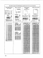
Il.
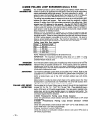
ZONE WPE
ZONE CONFIGURATIONS
DEFINITIONS
The 5140XM System albws up to M zones of hard-wire and polfing tip protection. Each zone must be assi~d
to a zone type, whkh defines the way in whiih the system respnds to fauhs in that zone. In addition, there are
several “system zones” for keypad panics, pelting ~p fauks, etc. whch must be assigned a zone type. Seethe
“SyQem Zone” section for a fist of these zones.
TW
00
Zone Hot Uaad
TW
01
Burglary
This zone type provides entry delay whenever the zone is faulted if the wntrol is
armed in the Away or Stay modes. When the panel is armed in the Instant or
Maximum modes, no entry delay is provided. Exit delay begins whenever the
mntrol is armed, regardless of the arming mode selected. These delays are
programmable. This zone type is usually assigned to sensors or mntacts on
doors through which primary entry and exit will take place.
Tyw
This zone type provides a secondary entry delay whenever the zone is faulted if
the panel is armed in the Away and Stay males. When the panel is armed in the
Instant or Maximum modes, no entry delay is provided. Secondary exit delay
begins whenever the mntrol is armed, regardless of the arming mode selected.
These delays are programmable. This zone type is usually assigned to sensors or
contacts on doors through which seconda~ entry and exit will take place, and
where more time might be needed to get to and from the ~nsole. Delay time must
be greater than Zone type 1. (Ex.: a garage, bading dock, or basement door)
Entry/Exit
#l
Entry~xlt
#2 Burglary
Perimeter
Interior,
Trouble
TyPS 03
Burglary
This zone type gives an instant alarm if the zone is fauked when the panel is
armed in the Away, Stay, Instant or Maximum modes. This zone type is usually
assigned to all sensors or contacts on efierior doors and wintiws.
TW
04
Follower
This zone type gives a delayed alarm (using the programmed Entry/exit time) f
the Entry/Exit zone is faulted first. Otherwise this zone type gives an instant
alarm. This zone type is active when the panel is armed in the Away or mmi’ m
modes. Maximum mode eliminates the delay though. This zone ty~~”s
bypassed
automatically
when the panel Is armed in the Stay or
Instant modes. This zone type is usually assigned to a zone covering an area
such as a foyer, bbby, or halhay through which one must pass upon entry (After
fauting the entry/exif zone to reach the console to disarm the system.) Since this
zone type is designed to provide an instant alarm if the ent~/exif zone is not
violated first, if will protect an area in the event an intruder hides on the premises
prior to the system being armed, or gains access to the premises through an
unprotected area.
rye
This zone type will give an instant alarm if faulted when armed in the Away, Stay,
Instant or Maximum (night) modes, During the disarmed state (day), the system
will provide a latched trouble sounding from the console (and a central station
report, if desired). This zone type is usually assigned to a zone which contains a
foil-protected door or window (such as in a store), or to a zone covering a
“sensitive” area such as a stock room, drug supply room, etc. This zone type can
also be used on a sensor or contact in an area where immediate notification of an
entry is desired.
TYW
24-hour
05
06
Silent Alarm
This zone type sends a report to the Central Station but provides no console
dsplay or sounding. This zone type ie usually assigned to a zone containing an
Emergency button.
TYW 07
Audible Alarm
This zone type sends a report to the Central Station, and provides an alarm sound
at the console, and an audible external alarm. This zone type is usually assigned
to a zone that has an Emergency button.
TYPS 08
Auxlliaq
Alarm
This zone type sends a report to Central Station and provides an alarm souti at
the console, (No bell output is provided). This zone type is usually
assigned to a zone containing a button for use in personal emergencies, or to a
zone containing non-fire related monitoring devices such as water se:=,s,
temperature sensors, etc.
24-hour
-6-
02
by Day/Alarm
by Night
24.hOur
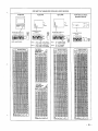
Program a zone wkh this zone type if the zone is not used.
Type 09
Supewiaed Fire (No
Verification)
Used for zones containing smke detectors (when smoke alarm verification is not
desired), or containing heat detectors, pull stations, etc. An open in this zonf? will
intiate a trouble sig~l. A s~ti in this zone will mtiate afire alarm.
Type 10
w/Delay
This zone type gives entry delay (usiW the programmed entry time), if tri[]ped
when the panel is amed in the Away rode. This zone type is also active dlJfing
maximum mode, but no delay is provided (alarms occur immediately if zone is
tripped). This zone type Is bypassed when the panel Is srmed in the
Stay or fnstant modes. Delay begins whenever sensors in this zone are
violated, regardless of whether or not an entry/exif delay zone was tripped first.
Type 16
Verification
Used when smke alarm verification Is desired on hardwire and polling loop zones
mnfaining only 2-wire or 4-wire smoke detedors. An open will initiate a trc,uble
response and a short initiates a fire alarm res~nse, Initial short detection causes
6 second smoke detector power reset. Subsequent short detection wit~n 90
smnds of reset causes fire alarm.
Type 17
Fire Waterflow
An open in this zone causes a trouble response. Shorts which remain present for
bnger than the programmable time delay cause a fire alarm response,
Ty~
18
Fire Supewiaory
This type is assigned to a zone haviW sensors which monitor fire sprinkler
systems ~.e. PIV switches, etc.). An own in this zone causes a trouble. Shofls
which remain present longer than the programmable time delay cause a
supervisory res~nse. Supervisory response will not activate a bell output,
Type 19
24 Hour Trouble
An open or shoti in this zone causes a trouble response. No external alarm
sounders are actuated.
,-.
itierlor
Fire Mth
,-
-.7-
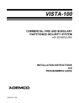
BASIC 8 HARD-WIRED
GENERAL
INFORMATION
ZONES (Zones 1-8)
All zones have a 350 milh-second resWnse and can be assigned any zone t~.
All zones provide class B (style B) supervision using a 2K EOL resistor (m
‘
610-7, supphed). The panel also supewises the zone wiring for eatih gro~
fauns.
When programmed for fire warning usage, all zones can monitor 4-wire smke
detectors (zone ty~s 9, 16), N.O. fire alarm initiating devices (zone types 9, 17)
or N.O. sprinkler system superviwry devices (zone type 18). When programmed
for burglary usage, all zones can mcnitor N.O. or N.C. alarm initiating devices. Use
any UL fisted N.O. or N.C. device not requiring power from the panel. Use only
those 4-wire smoke detectom Mstedbelow.
Note that power for 4-wire smoke detectors is supptied by the pane~s auxitiary
power #1 output and thb power mst be switched using the ~n~n auxi[ary relay
to allow the detectors to be reset via the second entry of an OFF sequenm ~.e.:
semrity code + OFF key) at a mnsole folbwing an slam. Also mte that a System
Sensor A77-71 6-01 EOL relay module must be used to supewise the power
mnne~lons to 4-wire smoke detectors. See the AUXILIARY RELAY section for
programming and wiring information. Zones which are programmed for fire with
alarm verification respnse (zone type 16) should only be used to monitor smoke
detectors.
Connect N.C. devices In series with the zone wires and connect N.O. devices
across (In parallel with) the zone wires. Obsewe polarity when wiring smoke
detectors. Connect the 2K EOL resistor across the zone wires at the last device.
The maximum zone resistance is 100 ohms for zones 1, 2 and 6 and 300 ohms
for all other zones (excluding the 2K EOL resistor).
Compstlble
4-Wire Smoke Detectors
You may use as many 4-tire smoke detectom as can be powered from the paners
auxitiary power 1 output without exceeding this outpu~s rating (see the
POWERING THE SYSTEM section for auxiiary POwer ratings)
I System Sensor 2412 w
Photoelectric, direct wire
! System Sensor 2412TH
Photoelectric w/heat sensor, dhect wire
I System Sensor 1412
Ionization, direct wire
ZONES 1 & Z 2-~RE
DETECTORS
SMO=
These zones have the added cspabihty of suppoting 2-wire smke detectors.
Each zone provides enough sta~by current (2 MA) to pwer up to sixteen of the
smoke detectors fisted bebw. Each zone provides only enough alarm current (20
mA) to power one smoke detedor in the alarmed state. When assigned zone
type 9 or 16, the second entry of an OFF sequewe at a console will interrupt
power to these zones to albw detectors to be reset folbwing an alanw.
Compstlble
2-Wire Smoke Detectors
You may use up to sixteen 2-wire smke detectors on zone 1 and on zone 2 as
found in the table below.
DETECTOR TYPE
Photoelectric w/heat sensor, direct wire
Photoelectric, dir~ wire
Photoelectric w/heat sensor, direct wire
Photoelectric w/B401 B base
Photoelestnc w/heat sensor and B401B base
Ionization, direct wire
Ionization w/B401 B base
Photoelectric duct detect. w/DH400 base
Ionization duct detector w/DH400 base
DEVICE MODEL #
System Sensor 2300T
System Sensor 2400
System Sensor 2400TH
System Sensor 2451
System Sensor 2451TH
System Sensor 1400
System Sensor 1451
System Sensor 2451
System Sensor 1451 DH
NOTE These smoke detedors are Listed for use wth the 5140XM and are the only 2-wire
smoke detedors that may be ussd.
w
-8-
ALTERNATE
ZONE 6:
TAMPER
FUNCTION
,-
ZONE 7:
ALTERNATE
KEYSWITCH
FUNCTION
ZONE 8
TWO WfRE GLASS
BREAK DETECTORS
Ths zone maybe programmed to sewe as a tamper loop for the C-COM c;ibinet
and for the Ademco AB12 grade A burglary bell box. For Grade A Burglary
installations, field Y17 must be programmed to “l” to enab[e this function and
zone 6 should be assigned a day/night burglary res~nse (zone type 05). The
panel will initiate a day trouble/night alarm when an open or short circuit is
detected in this zone or when an earth ground fauk caused by tampering with the
AB12 burglary bell box is detected. See the BELL CIRCUIT OUTPUTS setion for
AB12 bell wiring information.
This zone may be programmed
KEYSWITCH
information.
section
for
to sewe as a keyswitch
keyswitch
programming,
input. See the REMOTE
wiring and operating
This zone has the added capatifify of supporting 2-wire latching type glass break
detectors. Use detedors which are wmpafible with the ratings fisted below. The
second ent~ of an OFF sequewe wilf interrupt zone power to allow detedors to
reset followiW an alarm.
Compatible
Z-wire Glass Break Detectors
Standby Voftage: 5VDC - 14VDC
Standby Resistance:
Greater than 20k ohms (equivalent resistance ~ofall
detectors in parallel)
Alarm Resistance: Less than 1.lk ohms (see note below)
Alarm Current
2 MA -10 MA
Reset Tree:
Less than 6 semnds
The IEl 735L series detectors have been tested and found to be compatible?with
these ratings. Up to 50 IEI 735L deteaors, mnnected in parallel, maybe used
(the alarm current provided by this zone is sufficient to support operation 0[ only
one detector in alarmed state). Follow the manufacturers recommendatiot~s on
proper detector installation.
NOTES:
. Detectors which exceed 1.1k ohms in alarm, but maintain a voltage drop in
alarm of less than 3.8 votfs can also W used.
. Use of N.O. or N.C. contatis on the same zone may prevent proper glass
break detector operation.
-9-
2-WIRE
GENERAL
INFORMATION
POLLING LOOP EXPANSION (Zones 9-64)
The 5140XM provides a built-in 2-wire polling loop interface which allows the
number of zones to be expanded from the basic 8 zones to UPto ~ zones u.sin9
various addressable polfing loop sensors. The panel supewises the ~lhn~
\p
wiring for open, short and earth ground faufts. See below for a fist of comptile
sensors and for comments regarding reefritions on burglary and fire usage.
The potting loop provides power to sensors and serves as a mmmunication path
between fhe panel and sensors. Each sensor must be assigned a unique
address ID number (from 9-64) before being connected to the polfing loop. Most
sensors have DIP switches for this purpose. See the DIP SWITCH SETTING
TABLE FOR POLLING LOOP DEVICES for information on how to assign ID
numbers using DIP switches. Care must be taken to assign unique ID numbers to
each sensor in order to allow the panel to supervise and provide unique wnsole
sfatus indications for individual sensors.
Sensors can be connected to a single run, or groups of sensors may be
connected fo separate wire runs without affefing the pane~s atifity to supervise
individual senmrs. Follow the wiring instmcfions provided with individual sensors
(4190WH wiring diagram is provided at the end of this manual). Be sure to
observe sensor polarify when wiring. The maximum allowable wire run length
between the panel and the last sen~r on a given wire wn is as follows:
Pollin
Loo
Wire Run Lengths
=
NOTE: Twisted pair remmmetied for all normal wire runs.
IMPORTANT: The maximum comtined polfing loop run is 400V. If using
shielded wire, the maximum is 2000. If longer wire runs are needed, a 4197 Loop
Extender Module must be used.
INTERCOM
INTERFERENCE
ADVISORIES
POLLING LOOP SMOKE
DETECTORS
-1o-
If an intercom system is being used, the ~lhng loop wires must be as far frorn%he
intercom wiring as possible (minimum 6). If this spacing cannot be achieved,
shielded wire must be used. If this is not done, interference on the intercom
system might occur. Also note that the maximum total wire length sup~rted is cut
in hati when shielded wire is used.
The maximum allowable current draw on the polhng loop is 84mA. Refer to the
POLLING LOOP CURRENT DRAW WORKSHEET (found in the POWERING THE
SYSTEM section) for current draws of various Wlfing loop devices. If more than
64mA is being drawn, use of the 4197 provides another loop with 64mA
avdlable.
Make certain to include the total current drawn on the pelting loop in the Total
Standby/Alarm Load Worksheet (see POWERING THE SYSTEM section) when
figuring the total auxihary load on the pane~s power supply.
Can be added to the 2-wire Poling Loop on zones 9 through 84 (as programmed
in fields ’03, ’04, ’05, 1’01, 1’02, 1.03, 1’04 and 1.05). These detectors have a
buiti-in RPM which is DIP switch programmable. They are wired in parallel to the
pelting loop, and do not need auxikay power or a separate reset switch. The
polfing loop provides power and reset signals to the detectors, as well as alarm
and frouble signals from the detectors.
4192SD Photoelectric
Polling Loop Smoke Detector
Direct wire photoelectric smoke detector wifh built-in RPM which is DIP switch
programmable.
4192SDT
Photoelectric
Polling
Loop
Smoke
Detector
w/Heat
Detector
Direct wire photoelectric smoke’ detector with f 35°F (57°C) heat detector, and
buiti-in RPM which is DIP switch programmable.
w
4192CP Ionization
Smoke Detector
DireCl wire products of combustion ionization detector with buik.in RPM which is
DIP switch programmable.
PASSIVE
MOTION
INFRARED
DETECTORS
,.-
MISCELLANEOUS
POLLING LOOP
DEVICES
Refer to the PIR Installation Instructions for installation hints” as to the best
mounting Iocation forthese devices.
4278 Quad Element Polling Loop PIR
Quad element PIR with built-in RPM which is DIP switch programmabh? and
mnnecfe drectlyto the polhng hop. Includes mirrors for both wide angl~?and
cudain/long range applications. NOTE: The built-in auxihary aensorloop ia not
supewieed and should Mt be used.
4275 Dual Elament Polling Loop PIR
Dual element PIRwith built-in RPMwMch is DIP switch programmable. Includes
mirrors for both wide angle andcutiaitilong
range apphcafions andcan use the
1875PA Pet Alley mirror. Built-in selectable pulse count capabitify.
4194 Surface Mounted Reed Contact (Wide Gap)
Wide gap surface mounted reed confacf with buik-in RPM, which is DIP switch
programmable.
4190WH Two Zone Remote Point Module
Used to supewise conventional N.O./N.C. devices via the polling loop, and has a
tamper supervised cover.
Provides one class B (style B) supervised (Ieft)loop for monitoring fire alarm,
sprinkler superviso~ and burglary senmrs. NOTE: N.O. fire/sprinkler devfces met
be (style B) supervised using a 4.7k EOLR (model 610;11; purchased sepiirately
as pati of 41OOEOLR Resistor ~t~. N.O. and N.C. burglary devices may be
supewised using either a4.7kor30k
EOLR. Note that the second unsupewised
(right) loop should not be used. DIP switch programmable zone nutier.
4208 Eight Zone Polling Loop Expansion Module
Used to supervise conventional N.O./N.C. devices via the polhng loop. Provides 8
class B(style B) supervised Ioopsfor monitoring fire alarm, sprinkler supe!visov
and burgla~ sensors.
NOTE: The fhst six krops are (style B) supervised using a4.7k EOLR arid can
monitor either N.O. fire alartisprinkler
supervisory devices or N. O./N.C. b~jrglary
devices. The last two loops are supervised using a 30k EOLR and can only be
used to monitor N.O.W.C. burglary devices.
Note that the 4208 must either be mounted inside the 5140XM cabinet <Irin a
separate enclosure which hasatamper
supervised cover when used to monitor
burglary devices.
DIP switch programmable zone numbers. The first two loops can be selected for
either normal or fast response (DIP switch selectable).
4197 Polling Loop Extender
Module
At present, the4197 is UL Listed for burgla~ appticafions only. Can be used if the
2-wire polhng loop must be greater than the recommended length (4000 mm). By
instalhng a 4197 at the end of the first loop, the polfing loop can be continued. If
more than 64mA needs to be drawn from the pelting loop to power RPMs, use of
the 4197 p,~vides a~fher loop with 64mA available. Connects to the polhrlg loop
and must be Wwered from auxifiay power #l output.
-11–
SYSTEM ZONES (Zones 70GENERAL
INFORMATION
99)
Aside from the 64 hardwire and polfing loop sensor zones, the 5140XM provides
a number of additional zones which are dedicated to monitoring various aspects
of system behavior. These system zones are listed below. The “system zor “
number appears in the console display window when a fault contition associati
with this zone is detected. The zone types programmed in field 3’10 (for zones
70-75) and field ’05 (for zones 95-99) determine the panel’s response to “system
zone” faults.
Zone #70: Bell Output 1: Monitors bell 1 outpu~s supewision status (if enabled
at installation time). See the BELL CIRCUIT OUTPUTS section for
more information.
Zone #71: Bell Output 2: Monitors bell 2 outpu~s supervision status ct enabled
at installation time). See the BELL CIRCUIT OUTPUTS section for
more information.
Zone #72: Earth Ground: Monitors the panel’s field wiring to determine if an
eatih ground fault exists. Ttis zone’s default type is set to [19] (24
hour trouble) to provide a trouble response to earth ground faults.
When the panel detects an earth ground fault caused by tampering
with (i.e.: drilling through) the Ademco AB12 grade A burglary bell
box, it overrides the zone 72 fault response and instead ttiggers a
zone 6 alarm (if enabled in field 3’1 7).
Zone #73: J2 Input: Monitors the status of Input 1 on the main PCB J2 header.
Input 1 can be used to monitor the “Xmit Okay” signal from the
7620ULF LORRA. See the TRIGGER OUTPUTS section for more
information.
Zone #74
Dialer Line 1: Monitors the supervision status of the main dialer
output (K enabled at installation time). See the DIALER OUTPUTS
section for more information.
Zone #75: Dialer Line 2: Monitors the supe~ision status of the optional
5140DLM back-up dialer module’s output (if installed/enabled
installation time). See the DIALER OUTPUTS section for rob_,
information.
Zone #76: Auxiliary Relay: Assigned to the built-in auxiliary relay for the
purposes of allowing the operation of this relay to be bypassed.
Wnce the auxilia~ relay is not supervised, this zone does not monitor
anytting and cannot be assigned a zone type.
Zone #77
LORRA Triggers: Assigned to the LORRA triggers on the main PCB
J2 header for the purposes of allowing the operation of these
triggers to be bypassed. Since the LORRA triggers are not
supervised, this zone does not monitor an~hing and cannot be
assigned a zone type.
Zone #95: Keypad Panic: Activated by simultaneous depression of the console
~] and [1] keys. See the KEYPAD FUNCTIONS section for more
information.
Zone #96: Keypad Panic: Activated by simultaneous depression of the console
[#] and [3] keys. See the KEYPAD FUNCTIONS section for more
information,
Zone #97: Polling Loop Short: Monitors the polbng loop wiring for short circuit
faults, See the POLLING LOOP section for more information.
Zone #99: Keypad Panic: Activated by simultaneous depression of the console
~] and [#] keys. See the KEYPAD FUNCTIONS section for more
information.
-12-
III. PERIPHEWL
REMOTE
F.,
GENERAL
INFORMATION
TWO CONSOLE
PORTS
DEVICES
CONSOLES
The 5140XM panel interfaces to 5137AD (gray bezel) and 5137ADR (red bezel)
alpha custom LCD consoles. These consoles provide visual and audible
indication of system status and allow the user to enter system operating
commands. These consoles provide the following features:
. 2-fine, 32 character(16 characters per hne) alpha numeric LCD display wtich
provides a programmable “Enghsh Language” description for each zone.
. 12 key telephone style keypad. The keys are back-~i.
. Built-in sounder which provides audible indications of alarm, fire supervisory
and trouble conditions.
. Choice of gray or red front bezel.
NOTE: Many municipa~ties require that fire system annunciators be red in color,
Check wlh the authodfy having jurisdiction before choosing a console color for
your installation.
. 90 mA current draw.
The 5140XM provides 2 console interface Pfls. Port 1 uses terminals 11.14 on
the main PCB terminal block and port 2 usee pins 1,4,5,, 7 on the main PCB J4
connector as indicated below. The wrt 2 ~wer/data wires are elecfricallv isolated
from (i.e. not affected by open, short or earth ground faults on) wrt 1 ~wer/data
wires. Note that the 4142TR nine wire cable (1 cable suppfied) is used to m:ike
connections to the J4 connector.
Port 1
terminal 11: aux power#l output (to mnaole red wire)
terminal 12: ground (to mnsole black wire)
terminal 13: data in 1 (to console green wire)
terminal 14: data out 1 (to console yellow wire)
Port 2
J4/pin 1: ground (to console black wire)
J4/pin 4: data in 2 (to mnsole green wire)
J4/pin 5: aux power W output (to console red wire)
J4/pin 7: data out 2 (to console yellow wire)
When only 1 console will be used in the installation, this console must be
mounted on or near the cahnet (see the MOUNTING THE CONSOLES section)
and may be wired to either wrt. When more than 1 console will b installed, the
“main” console must be mounted on or near the caMnet and must be wired to
Pod 2. The “suppleme~ary” consoles can be mounted where desired and must
be wired to Port 1. The “main” console will continue to function even when wiring
faults prevent the “supplemental”
consolee from operating properly, Note that
the panel can detect earth ground faults on Port 1 and 2 wiring but does not
supewise this wiring for open and short circuit faults.
-
1:3-
POWRING
AND
WIRING
The 5140XM suppods, independent of auxiliary power considerations, up to
sixteen 5137AD/51 37ADR mnsoles. The 5140XM can supply up to 1 amp of
euxitiaw standby power for consoles, pelting loop devices, motion detectors, 4wire smke detecfom, etc. (the maximum auxiliary standby bad that mn be drawn
t
is hinted by the capaciy of the backup battery used. A 1 amp load requires a
AH battery. See the POWERING THE SYSTEM section for more informat~).
Provided that the maximum permissible standby load is not exceeded, up to 11
consoles (at 90mA per wnsole) can be powered from the pane~s auxifiary power
1 and auxihary power 2 outputs. Keep this in mind when adding consoles so that
the pane~s power supply is not overloaded resulting in a battery which does not
properly charge.
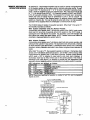
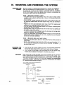
If the pane~s maximum permissible standby load is exceeded, then additional
mnsoles an~or other auxilia~ devices can be powered from a separate UL
Commercial Listed Wwer supply. The Alarm-Saf model AS/PS5-BFS-l 2-UL
Commercial Fire Listed supply can be used to power additional consoles and/or
other auxiliaw fire davices. The dia~ram below shows how to make connections
to the Alarm -Saf power supply.
R,ure
2. MM
-SW
POWER
SUPPLY
CONNE~ON
DIAGWM
Supplementary consoles may be wired to a single wire run or individual consoles
may be mnnacfed to separate wire rims. The maximum wire run length from the
panel to a mnsole whwh is homrun back to the panel must not exceed:
. ------ .“
CONSOLE WIRE RUN LtNU I nZ
If more than one console is wired to a single
run, then the a~ve maximum lengths must
be divided by the number of consoles on
F
the
run (i.e. the maximum length would be
,#,6*1
gaugewn)
225 feet if two consoles are wired on a #22
NOTE: The length of all wire runs mmbined must not exceed 2000 feet when
unshielded quad mnducfor cable is used (1000 feet ff shielded cable is used.)
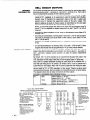
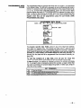
ADDRESSABLE
CONSOLE DIP SWITCH
SETTINGS
-14–
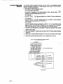
The 5137AD
and 5137ADR mnwles
are addressable
devices.
They have a built-
in DIP switch which is used to select their operating address. Each console used
must be assigned a unique address for proper system operation. Refer 10 the
figure and table below to set this DIP swtch. The panel can be programmed to tell
it what sounding options should be used for each console (refer to DEVICE
PROGRAMMING in the PROGRAMMING THE SYSTEM section for more
information). The pane~s standard factory default enables all console addresses
and sets each console for no sounder suppression. You only need to use the
Device Programming Mode at initial installation if you desire to change ‘he
sounder options for one or more consoles.
-,,
NOTE: Some versions of the 5137AD/5137ADR mnsoles have a sixth DIP
swich. Make sure that fhe sixth swtch is in the DOWN psifion.
CONSOL,E DIP SEmNGS
~
NOTE: &me versions of tie
5137AD15137ADRmnsole may
hw a 6 psition DIPstiti. Tk
sixth swimh should b put In
tk ~WN ~itti.
ADDRESS “31 “
b
not use address
31.
~ss
31 muses h cmd
m owm@ in non-&dres~Ue
mode
(i.e.
works like a
~.
nmdesmtie
5137
I
–15-
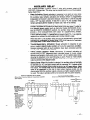
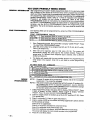
BELL CIRCUIT OUTPUTS
GENERAL
INFORMATION
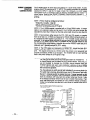
The 5140XM provides two ball circuit outputs for operating fire and burglary alarm
indicating devices (belll -terminals 3,4andbe112
-terminals 5,6). Each oulouf
may be independently selected for the following features:
.,
. class B (style Y) supervision (used for fire bell circuits) using a 2K EOL resi~-or
(model 610-7, supphed) or m supervision (used for burglary bell circuts).
System zone 70 monitors the supewision
status of the bell 1 output and
system zone 71 monitors the supewision
status of the bell 2 output. The
pane~s response to fauks on these outputs is determined by the zone type
programmed in field 3’10 for the wrrespanding
system zone.
NOTE: Cutthewhite~mper
(zone 71) for no res~nse
required.
POWR
AND
WRING
Wl (W4)onthe
main PCBandprogram
zone70
to disable supervision for bell 1 (bell 2). No EOLR
.
activation by alarm candtions
through 3’61)
.
short ding for canfirmtion
of arming (field’16 for bell 1, 3“57 for ball 2) and for
entry/exif or perimeter zone fauks while CHIME mode is active (field 1.47 for
bell 1,3’59 for bell 2)
.
activation
3’1 5)
.
2 to 30 minute timeout or no timeout (field’ 13 for bell 1,3’60 for bell 2). Note:
burglary bell circuits must be programmed for 16 (or more) minute timeout.
on one, some or all protection zones (fieWs 3’70
in a steady or pulsing manner
in response
to alarm candfiion
(field
Each bell outpuf is rated as follows: 10VDC
14VDC, 2.3 amps max., pwer
Umited. Note that the total alarm mrrent drawn from the aux power 1, aux power 2,
bell 1 and bell 2 outputs cannot exceed 2.3 amps for battery independent
operation.
By default, bell 1 is set to operate as an unsupewised
burglary ball output. You
may use any UL hsted, non-palafized burg laW indicating device rated for 10-14
VDC operation on this output. Note that a local burglary grade A tisting reqt
:
that a bell in a tamper protected housing be used (such as the Adem
A=)
and that bell wiring be run in conduit. By defauk, bell 2 is set to operate as a
supervised fire bell output. Note that the panel supervises this wiring for open,
shod and earth ground fauks. You may use any UL fisted, polarized fire indiiati~
device rated for 10-14 VDC operation on this output. Observe polarity when
wiring polarized devices. Some examples of mmpafible devices are given babw.
The diaaram shows how to make connections to these outputs.
Exampl;s
Burglary
Fire
of Compatible Alarm indicating Devices
Bells
AdemwAB12
(9rade A bel~housing)
Bells
AdemmWFP8-12
(W bell)
Ademm WFP1O-12
(10” bell)
System Sensor PA400R
(red piezo horn)
Horns
System Sensor MA-1224
(red horn)
System Sensor MAfSS-12 (horn and strobe)
System Sensor SS-12
Strobes
~g”re 4. BELL CIRCUIT WIRING
(Shows wiring for bell o.tp.t*
configured using fadow
default programming
selections)
BELL 1 FACTORY DEFAULTS
~: ;i~~flg.red
.S a b“’gtav
. use non-polarized Gmde A
indcating devices leg Ademco
N.. AB12 see below)
. Wiring is not s“pewlsed ...!
whhte jumper, W?, on mat. PCB
. Activates for ,.”,s 3.8 .[am.
. Steady al.m .utPut
. 16 minute timmut
BELL z FACTORY DEFAUL=
Bell 2 is con fig”,ed as a fir. bet!
.,,.,,,,
.m
”...
.Us. Wlatized Indicat,”g
devices
. C!ass B oDen/shofl supewisio”
.24 h, trouble cesPo”* tO f~UltS
. Activates for .0”, 1, 2 .l.ms
. Pulsed alarm outPut
. No timeout
“,.
–16–
3
4
AS32 BELWBOX WIRING
5
hBt 2 WIRING NO=S
. D,sco””mt the ml 2S
fati.v wires .o”.mNo”
“al #4 to K
6
. ...
+
BELL;
+BELL 2
12~::LRl
(M:=~
. Zone 6 should be
Programmti f.r a day
tw.blelnight slam (qpe
or 24 hour slam (WPe07
response
. w,,, Pa”el, s door tamw
switch in series with z..
. AII wiring from AB12 to
~o;yt
be W. in
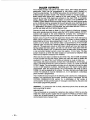
AUXILIARY
RELAY
The 5140XM provides a built-in “Form C“ relay with contacts rated at 28
VACNDC, 2.8 amps max. This relay maybe programmed for one of the funcfbns
betow (field 3’61):
,-
.
Alarm Activation:
Steady acfivatin
in response to an alarm on one, some
or all zones as selected in fie~s 3’70 through 3’81. If field 361 is set to”1”,
the auxiliay
relay remains asfivated until timeout (which is programmed
independent of the bell 1 and bell 2 timeouts; tieti 3’60) or until the 5eCurify
code + OFF has been entered. If field 3’61 is set to ‘4, the auxihary relay
remains activated until the installer or master mde + [#] +67 is entered.
When this functiin is used, the auxiha~ relay Hn be used for elevator recall or
ventilator shutdown on fire alarms or when wired to the aux power 1 output or
to a separate power supply (such as Alarm-Saf model AS/PS5-BFS-l
2-UL
see the REMOTE CONSOLES section), the auxiliary relay can be used to
provide a third (unsupewised)
bell output for supplementa~
strobes,
sounders, etc. as irrdiiatad in the diagram, below. By defauk, the auxilia~f relay
is sef to acfiiafe on zone 1-8 alarms with no timeout (field 3“61 =1 ) as m“~hf W
required for a common fire and burglaV alarm strobe itilmtor
usage.
When fieM 3’61=1, the auxiliary relay can also be programmed to give a brief
ativafion
for confirmation of arming (field 757) or for errfry/exit or perimeter
zone fauks while CHIME me
is active (fieti 759).
Rgure
(Shows
slam
.
Trouble/Supervisory
Activation:
Steady activation in response to any
zone or system related trouble co~tion
or to any fire supervisory condiiin.
Remains activated until all fault conditions have been corrected and the
security de
+ OFF has been entered.
.
4-Wire
Smoke
Detector
Reset:
Momentary
(6 second)
activation
at
second entry of OFF sequence wtich interrupts power to 4-wire smoke
detectors connected to hard-wired zones (zones 1-8) or to polfing tip
zones,
allowing the detectors to be reset following an alarm. Power to 4-wire smoke
detectors should be wired to the auxitia~ relay and to the auxilia~ power 1
output as shown in the diagram bebw.
.
Batte~ Savefi When ttis function is selected, the auxiha~ relay will normally
be activated ~.e. N.O. and pole contacts will be connected, N.C. confa~ will be
open) and will de-advate
4 hours after the stafi of an AC power failure. Using
this feature, noncritical toads (such as supplementary mnsoles) which do no
need to be supported for the full 24 hour baffeV backup period can be
disconnected from the auxitiary outputs, allowing a smaller capacity battery to
be used. The relay re-acfivates within a few seconds after AC power restores.
5a. AUXILIARY
how to wire A..
REMY
WIRING
Relay for .nsupewisd,
figure 5b. AUXIL1~Y REWY WIRING
(Show how to ware.“, relay for 4-wire moke deltior
poweti
wwer 1=.1)
output.)
-
ALARM
r/7
11et2
78910
AUX REMY
FACTORY DEFAULTS
. Activates for zones 1-8
alms
(steady alm
output)
. No t,meo”t
NOTES
. u.. no.-polatiz~
i“ticati”g
devices
. wring is not
..pemised
. Do not exceed !he
raflngs of the SUPPIY
u=O. 17au. pwr 1
output used, then
c.mtined slam
c.ment drawn from
,“. pwr 1, a.x pwr 2,
bell 7 and bell 2
.a..ot
,xce&
2.3A mm.
)
.
~
:
:
:
n
/“
:
x
2
;
cAN DWW pOWERFROMWE AUX WR 1
OUTPUTOR FROMSEPAWTE SUPPLY
+-
0
z
;
I
I
&J
EOLR
.- 17 –
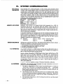
DIALER OUTPUTS
The 5140XM provides one Wik-in main dialer output, with vokage and current
supervision,
wtich can be programmed
to use either rotary (default)
or
TouchTone dal formats. The 5140XM also allows for mnneti~n
of an optk - ~
5140DLM back-up dialer module. This module provides a semnd superv~~
dialer output which sewes as a back-up to the main output. The 5140DLM
mounts to the main PCB shield and connects to the main PCB J3 connector
using a ribbon cable (supplied with module) as shown in the SUMMARY OF
CONNECTIONS dagram at the e~ of this manual. Note: the earth ground screw
on the 5140DLM must be mnnecfed to the earth ground screw (terminal 30) on
the main PCB using 16 AWG wire. For Listed Rre Central Station (UL864~FPA
71) apphcatins,
use either a LORRA abne, the main dialer with the LORRA, or
use the main dialer with the 5140DLM Backup Dialer.
Connect the main and back-up dialer of used) outputs to telephone mmpany
hnes which provkfe bp start sewice using the RJ31 X cables supplied. DO NOT
connect both outputs to the same telephone
company
line. Connection
to
telephone co~any
fines w~ch prov@e ground start sewice is not permtied.
System zones 74 and 75 monitor the supervision statua of the main and back-p
dialer outputs respectively. The pane~s response to fauks on these outputs is
determined by the zone type programmed in field 3’10
for the corresponding
system zone. By defauh, zone 74/main tialer is programmed for 24 hour trouble
response (type 19) and zone 75back-up dialer is programmed
for no res~nse
(type 00). The supewision circuits on both dialer outputs will trip a fauti when the
tip/ring vo~age falls bebw approx. 25 volts (13 voffs for the main tialer when the
main PCB blue jumper is cut; 13 VORSfor the back-up dialer when ~s blue jumper
is cut) and when handset current is less than approx. 10 mA. Note: The blue
jumper should be cut when the dialer outputs are connected to telephone fines
which have a telephone company MTU installed.
When only the main daler is enabled ([1,0] in field 3.30), the 5140XM will attempt
to route all calls over the main output. When both main and back-up dialers are
enabled ([1,1 ] in fie~ 3+30), the 5140XM will attempt to route all calls over
~
main output until a faui is detected, at which time if will attempt to use the ba%~
output. Line fauhs will resuh in a zone 74-DIALER 1 FAULT or a zone 75-DIALER
2 FAULT display. The mmmunicator will makeup to 8 attempts to transmt a repoti
to one or both telephone numbers, dependrrg
upon the repon routing option
programmed, After the eighfh attempt, the communicator
will hang up and a
COMM FAIL will be displayed at the conwle. The dialer attempts are programmed
in field 3’21 (default=8; must be restricted to 3, 4 or 5 attempts if a semndary
phone number is programmed).
The 5140XM will transmit reports in the following order alarms (fire, medice~pank,
burgla~), fire supervisories and troubles, remaining types of messages. See the
SYSTEM
COMMUNICATION
section for a description
of the variety of
mmmunicafion
formats and the types of messages transmitted by the panel and
for the dialer programming defauks.
WARNING:
To prevent the risk of shock, disconnect
before servicing the panel.
phone
lines at telm
jack
IMPORTANT
If the mmmunicator
is connected to a telephone line inside a PABX, be sure the
PABX has a back-up power supply that can supwrf the PABX for 24 hours. Many
PABXS are not Mwer backed uo and connection to such a PABX will resuk in a
mmmunicafion iailure if Wwer is lost.
-18-
,n
The J2 connedor,
located in the upper right hand mrner of the main PCB,
provides 1 input (labeled INPUT 1) and seven tr~ger outputs (labeled OIJT 1OUT 7) that can ~ used to interface to the following:
GENERAL
INFORMATION
.
.
.
.
Remote mnsole sounder
UL Listed keyewitch
5140LED Indcator Module
Auxitiary alarm signahW quipment
such as the Ademm 7620ULF Subscriber
Radio
. Event logging serial printer (via4100SM Module)
. PC computer used to dired wire download the pane~s operating parameters
(via 4100SM Module)
The pin assignments for the J2 mnnedor are shown in the diagram bebw. Use a
4142TR 9-wire trgger oable (1 supphad) to m~e Connations
to this mnnmor,
The panel does mt supewiae fie~ wiring mnne~ed
to this mnnedor.
The trigger output ratings are listed
outputs
1, 5, 7:
LOW:
HGH:
Remsining
Outputs:
LOW:
HGH
bebw.
2K to
10-14
IK to
10-14
Note: all outputs are power limited.
ground
V~ @ 20 MA max
ground
VDC through 5K
Program fields 3.19 & 3’20 are used to Seled the funtions
1-7 as indicated in the dagram below.
Kg”,,
6. J2 PIN ASSIGNM
ENS
mo
of INPUT 1 an[~ OUT
F“NCmONS
,2 CON
-
[
04(
L
E
::
#
-19-
*MOTE
CONSOLE
SOUNDER
OPEWTIONNIRING
An optional Amseco PAL328N
piezo sounder can be used for installations
where it is desired to remote the sounds produced by the console’s built-in
sounder. The panel will remote all sounds (i.e. alarm, trouble, chime, entry/exi,
etc.) produced by the console’s Wilt-in sounder except for the short key cl;,’ :
associated with console key depressbn. One app~cation of this feature migh~
to produce chime sounds in a tiafion
whwh is distant from the pane~s wrrsoles.
If used, program fiekf3”20
must be set to “W (facfory default) to enable the
remote sounder option, and the PAL328N must bewnnecfed
to JZOUT5
aa
shown in the Remote Console %under diagram.
J2 CONNECTOR
-.
-20–
IWMOTE
=YSWITCH
OPE-TIONMIRING
,-
An optional UL Listed remote keyswitch ~n be used for remote armin@disarmiW
of the burglary portion of the system and for remotely silencing alarms. If used,
program fieti “15 mu~ be set to “1- or “2” to select a keyswifch operating mode.
Zone 7 must be assigned a non-zero response type. Also, fie~ 3’20 must b set
to ‘1” t it is desired to use J20UT 1,5 to o~rate keyswifch ARMED a~ RFADY
LEDs (if keyswitch provides LEDs). The keyswitc~s normally open momentary
switch ad LEDs (it used) must be connected to zone 7 and to J20UT
1,5
respectively as shown in the diagram bbw.
An optional cbsed circuit tamper
switch (ex. Adem
~. 112) can be wired in series wth zone 7 so that keyswifch
operation will be dbsblad when the swfichplate is remved from the wall.
The 5140XM allows 2 modes of keyswitch operation. When field ’15 is set to ‘1-,
the keyswtich operates as follows:
With System
Disarmed
and No Alarms
Present:
A momentary short across zone 7 will arm the system in the AWAY mode, and a
short held for more than 3 seconds will arm the system in the STAY rode. A
subsequent short will disarm the system. The keyswitch LEDs will indicate that
the system has armed (see table below). NOTE: FauRed zones must ei~r
be
comecfed or bypassed before the system will arm.
With Alarms
Present:
A momenta~ skrt across zone 7 will silence alarm bell and mnsole sounds, ati
will disarm the system if t was armed. The keyswfich LEDs will provtie a memory
of alarm indication (see table bebw). A subsequent short across zone 7 will clear
the alarm memory indkkation and reset 2-wire smoke am glass break detectors (f
used).
When field ’15 is set to “2”, the keyswitch operates as follows A mmenfary
short
across zone 7 will silence slam ball sounds ~.e. turn off Bell 1, Bell 2 and aux relay
t programmed for alarms) only ti a fire alarm is present. Outputs remain siltmcad
until a code + OFF is entered to reset alarms and clear alarm displays. A
momentary short has no effect if there are no fire alarms present. Thb mode is
intended to be used where it is desired to provide the fire deparfmenu with
keyswitch silence capsbi~iy wtihout compromising the burglary system’s semrify.
LED indications
are defined as follows:
MWING
GREEN RED
DBARMED & NOT R~DY
OFF
OFF
m
OFF
DISARMED & R~DY
ON STEADY
ARMED AWAY
OFF
ARMED STAY
OFF
SLOW FLASH
OFF
RAPID FLASH
MM
MENRY
NOTE: Open/close reporting for keyswitch is enabled in field ’40, and the keyswfich
reptis as user O
If “w
figure 8. KWSW~CH WIRING
W5.16 .75,. .1. or .2. for dad
kwstich retie
m, field 3.20 to ,,t. to .“*I.
ED d“w (KLED“~)
J2 CONNECTOR
.,-
–21-
5140LED
INDICATOR
MODULE
An optional 5140 LED Indicator Module can be used in municipahties
which
require deticated
indicators for communicator
fault status. The 5140 LED
provides the folbwing indicators:
. AC POWER: ON if AC pwer is present.
OFF if AC pwer is mt present.
b’
. COMM FAILURE: ON if maximum number of attempts were made (fieti 3.21)
to transmit a message to the central station. Enter security mde + OFF
following a successful transmission to turn off.
OFF t normal.
. DIALER 1 FAULT
ON if the main dialer fine is fauked. Correct problem and
then enter secui~ tie
+ OFF to turn off.
OFF if normal.
. DIALER 2 FAULT
ON if the ba~up dialer tine is faulted. Correct problem
and then enter security de+
OFF to turn off.
OFF if norml.
If used, program fieM 3“20 must be set to “2 to enable tMs option, and the
5140 LED module must be connected to J20UT
1, 3, 4, 5 as shown in the
diaaram below. The 5140LED is desianed to be mounted into a standard
Sindle aana elacfrbl
box. Follow the st~Ds below to install tMs module.
1. Pull fires from the pane~s J2 mnnector
through an opening in the siWle
gang box and splice these wires to the module’s flying leads. Solderless
sphces maybe used.
2. Mount the module’s PC board onto one side of the PC bard retainer bratiet
(supplied),
3. Slide the pC board retainer bra~et
into the box and fasten with screws
(supplied).
4. Mount the stainless steel decorative cover (supphed) onto the box.
figure
9.5140
LED INDICATOR MODULE
Ii “%d, St field 3.20 TO ‘2”
WIRING
J2 CDNNECTOR
414~
CABLE WIRES COLORS
5140KD
“
1111
AC POWER
8R0wN
AC POWER
o
COMMFAILURE
YELLOW
o
DIALER I FAULT
BLUE
o
D,,,,,,,,”,,
o
FUmRE USE
GREEN
COMM
OwNGE
DIALER 1 FAULT
VO ERM
11)
~
o
DIALER 2 FAULT
FAILURE
I
RED
+
TO :fi:”~R
1
0mRM12)
RED
BMGK
BMCK
%
t
5140LEQ MODULE
WIRES COLORS
–22–
MODULE
-,
AIWXILl,hRY
ALARM
SIGNALING
EQUIPMENT
The J2 connector provides triggers for fire alarm, burgla~/audble
pank alarm,
silent panic/duress
alarm, fire supervisory,
trouble and open/close
triggers.
These triggers may be used to trip auxiha~ alarm signating equipment such as
Ademco’s
7620ULF,
7720 and 7920SE Long Range Radios, 346 polarity
reversiW re[ayand 445 high hnesecurity transmitter. Note that not all of these
triggers
are available
for all setting of field 3’20.
Consult
the J2 PIN
ASSIGNMENTS AND FUNCTIONS diWram shown eartier.
The open/close trgger is LOW when the burglary system is armed, and HIGH
when disarmed. The remaining triggers are normally LOW and go HIGH when the
corresponding
fault co~~onowurs.
The fire, burglary/audible
panic atisilenl
panic/duress alarm triggers remain HIGH until the semrfiy code+ OFF is entered.
The fire supervisory and trouble triggers remain HIGH until the fault mnditon is
removed and the swrify
de
+ OFF is entered.
The diagrams below show how to make mnnections
to the 7620ULF, 7920SE,
346 and 445. Consuk the UL INSTALLATION
CHECKLIST
section for a
description of the spscifc 5140XM trigger connections and programming options
required for each of the various UL Listings.
EQU,, 17, ~MRIW
Wg”re ?0. 76211ULF WIRING
RWERSING
REUY
WIRING
DIAGWM
.!, CONNECT.*
“vOTERM*a
,, CONNECTOR
m
fio”m 12. w,
HIGH L(NE SECURIW DIRECT WIRE TWNSMl~ER
WIRING
7920SE WI RI NG DIAGWM
,2 coN,,.moR
.-.1
. . . . .rrl..
... ,”,,;,
,.. .,,.
from
.“.,,,
0...(
,,, .,
!0 7920SE
-,,,,,
=,.”!
..”.
!.
.. . . “...“.... . ”..,.
.......!,., s,. .,,,.,,s., ,s., ..,!.
uuI
!
-23-
E~NT
LOGGING
PRINTER
CONNECTIONS
The 5140XM allows its event log to be printed on a local serial printer. If used,
program field 3*1 9 must be set to”1”. NOTE: This setting overrides the functions
selected for INPUT 1 and OUT 2 made in field 3’20. Connect a UL EDP Listed
serial printer to the J2 mnnector using an Ademco 4100SM Intedacs modui~ ~s
shown below. Refer to the EVENT LOGGING PROCEDURES
section O-,S
manual for a description of the console commands which initiate event log
printing,
NOTE 1: Printer must be configured as follows:
.8 data bfis, no pa~y, 1 stop bi
.300 or 1200 baud (1200 preferred)
. Har*are
handshaking using DTR signal
NOTE 2: The4100SM
module is supphed wih a 10 foot RS232 cable. A longer
cable or an efiension cable can be used f the 5140XM and serial printer are
separated by more than 10 feet, but the total cable length should be less than 50
feet.
NOTE 3: Most printers either ignore the CTS, DSR and CD signals, or require
them to be high ~.e. 3-15VDC as measured on RS232 DB25 connector pins 5, 8
& 8 respedtvely wtih respect to grouti
pin 7). The 41 OOSM module sets these
pins Mgh. If the printer being used will not operate with these pins high, then” ctip
the blue (CTS), whfie’ (DSR) or red (CD) jumpers on the 4100SM module to set
the corresponding signal fbating. Important pins on the RS232C cable are pin 3
(data out), pin 7 (gmuti) ati pin 20 (DTR - ready).
NOTE 4: The DTR signal, as measured at 41 OOSM TB1, should be high (9.514VDC) when the printer is powered, properly connected, on-line and ready to
print, This signal will be low (O-1 .5VDC) when the printer is not powered, not
properly mnnecfed, oft-fine or out of paper. The 5140XM will not send printing
data to the printer unless the DTR signal is high.
NOTE 5:
If earth grou~ fauk sensing is enabled:
You may get an earth ground fault indcation when the 41 OOSM N
‘e
is clipped directly onto a sidewall of the 5140XM cabinet. If this o*,
use an insulator to insulate the 4100SM’S clip-on bracket from the
5140XM cabinet side wall. Later production versions of the 4100SM
have the chp~n bracket isolated from the circuit ground (terminal 7) and
will not have this problem.
You may alw get an earth ground fault indication if you use a printer (or
PC) which has a 3-prorrg, grounded pwer cord. [f this occurs, first verify
that pin 1 (chassis ground) is isolated from pin 7 (signal ground) on the
4100SM’S RS232 @nnector (early production versions of the 4100SM
have an unma~ed, 3/8 long, bare wire jumper lying near the pin 1 stie
of the RS232 connector which must be cut to isolate these pins). Then
verify that these pins are isolated on your prirrtefs RS232 connector.
Follow the instructions provided wfih your printer to isolate these pins if
required.
Figure 13. ~E~
,, .*,
–24-
x, ,.,,
s.,,,.
LOGGING
.,.
PRINmR
CONNECTIONS
DIRECT
WfRE
DOWNLOADING
,-
The 5140XM can be downloaded witbut
using a modem or telephone line by
using 4130PC Downbading Software ati a4100SM Serial Module. Ttis met~d
of downloading is referred to as DIRECT WIRE downloading. Connect a PC whch
runs the downloading
software to the 4100SM module as specified
in the
mdule’s
inatwcfiona. Connect the 41OOSM to the pane~s J2 headeras
shown
below.
IMPORTANT:
The
connection
between
the
5140XM
and
the
41OOSM are different
than those
shown
In the 41OOSM Installation
lnatructions.
Seediagram
below forcorrect connections. Inaddition, when the
“green” wire is referred to in step 2 of the IN CASE OF DIFFICULV
section of the
4100SM Instructions,
use the “vlolat”
wire.
Note also that the 4100SM violet wire connection
for computer
differs from that used when conneting
a serial printer.
Direct wire downloading can be intiated by following the procedures
the 4100SM’ instmtion
sheet.
terminals
described
mg”re 14. DIREU WIRE WWNLOADING CONNEaONS
“m.,,
I
+..
/
Em,.
m, ,Nw.mm
CODE + [q + [51TO INXRE
mWLOADING
BEFORE MKING
rnE AWE
cONNE~ONs
TO
AVOID 7R10aERIN0 A FAULT ON
IWn
1.
Nm
,,-
-25-
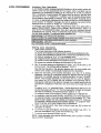
in
IV.
MOUNTING AND POWERING
MOUNTING
THE
CABINET
THE SYSTEM
Mount the cabinet to a sturdy wall using fasteners or anchors (not supp~ed) ir ~
clean, dry area w~ch is ~t readily accessible to the general pubtic. The bac~,
the cabinet has 4 holes for this pu~se.
Installations
which are intended to
provide hsted brgla~
sewke have special attack resistance considerations for
mounting the cabinet which are described below.
Grade A Mercantile
Premises
Llstlng
. The panel door must be supervised,
Mount the clip-on tamper switch
(supplied) to the cabine~s rghf side wall as shown in the diagram below and
wire it to zone 6.
. Use a bell with a tamper protected housing such as the Ademco AB12. The
bell busing’s
tam~r
switch and inner tamper linings must also be wired to
zone 6.
. Program zone 6 for day trouble/night
alarm (type 5, field ‘02)) resWnse and
enable the zone 6 akernate tamer function (field 3“1 7).
. All wiring between the ball ati panel must be run in conduit. Remaining wires
do not need to be run in conduit,
. All wiring which is wt mn in conduit must exit from the knock-out openi~s
on
the bottom or back of the cabinet.
. All unused knockouts must be plugged using the disc plugs and carriage hhs,
supphed, as indicated in the diagram below
. Fasten the cabinet door to the cabinet backhx
using the 16 one inch long
phitips heads screws (supptied) after all wiring, programming and checkout
procedures have been mmpleted
Grade A Mercantile
Safe and Vault Listing
. Follow the instructions given above for Mercantile Premises fisfirrg, except as
noted below.
. Mount a shock sensor such as Sentrol No. 5402 to the pane~s backbox. Fc’’+,v
the manufacfurets
instructions on proper sensor mounting. This sensor “._,.,t
also be wired to zone 6.
MOUNTING
THE
CABINET
LOCK
ADVISORY
1.
Insert the key into the bck. Position the lock in the hole mating certain that
the latch will make contact with the latch bracket when the door is closed.
2.
While holdng the Iwk steady, insefl the retainer chp into the retainer slots.
Postiin ckp as illustrated in the diagram to facilitate easy remval.
Make certain that the PCB mounting screws are reasonably tight to insure that
there is a good ground connection between the PC board and the cabinet. Also,
dress field wiring away from the microprocessor
(center) section of the PC board.
The cabinet provides 2 hops on ifs left and right sidewalls for anchoring field
wiring using tie wraps. These steps are important to minimizing the risk of panel
RF interference with television reception.
‘+D
,,”.
-26–
,.,s
K.ocK.om
.“.
AL,
w,,,,,..”
TO ,,”.
,.s,,.,.
“.”,,0
,.,. OF
A.
KNOCKOUT
O, E.ING, R,...,
0,s.
,,”.s
AND A CA..,..,
KNOCKO”T AN.
80,,.s
SHOWN
KNOCKO~/,,&,,,,,:,,:L:R:F
0,,.,..
REM,.,..
H,.,
>’
- c’””’’”
“o”
-
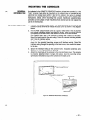
MOUNTING THE CONSOLES
n
:;uRFj\cE
GENERAL
INFORMATION
As indcated in the REMOTE CONSOLES section, at least one mnsole (i.e.: the
‘main” console) must ether be mounted on the ca~net door or mounted on an
electrical box located near (within 3 feet of) the cabinet. Run wires in conduit
between the electdcal box and the cabinet. Follow the SURFACE MOUNTING
instructions,
below, when mounting this console. Additional
supplemental
consoles can be surface or flush munted
where desired and do not require the
use of an electr~al hx.
MouN~,NG
1. Remove the console’s back cover. The securing screw at the tront of the
wnsole must be removed to release the back cover as shown in the dagram
below.
2.
For Dry Wall: usiW the back cover as a guide, make holes in the d~ wall for
the mnsole mounting screws and interface wiring. Pass the wiring through
the opening in the back wver, then munt ibis cover to the wall surface.
For Cabinet Door: use a 1/4 drill bit to enlarge the 3 holes on the door.
Mount the back cover to the door using 2 holes for console mounting screws
and 1 hole for interface wiring.
For Elecfri~l ~x: using the elecfriml box as a guide, make holes in the back
cover for the console mounting screws and interface wiring. Pass the
interface wiring through the opening in the back cover, then mount this rover
to the box.
3.
Splice the interface wiring to the console
sphces (i.e.:311) maybe used for splicing,
4.
Attach the main body of the @nsole to the mounted back cover. The mnsole
is properly attached when it snaps into place. Use the secuting screw
(previously removed) to secure the console to the back cover,
wires.
Insulated
solderless
wire
~.,
Back ,.,,,
ofVISTA
that is mounted
wiring through
\
and SPfice to Console
to the
Console
wa!l.
hole
wire*.
\
II
VISTA
securing
Figure
16. SURFACE
MOUNTING
Cons.,,
,Cre;
CONSOLES
-27-
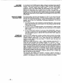
FLUSH MOUNTING
MTH
TRIM RING KIT
(5137TRK)
1.
Cut out a 4-3/4 high by W wide opening in the wall between studs, no less
than 1-1/2 from ether stud. Use the template provided to mark the cut-ut.
~
Insert the four l-1/Z bW #6 screws through the mounting holes in the Trim
Ring and then attach the four metal securing clips, as shown in the diag~ I.
Use only two or three turns of each screw, allowing the metal chps to ~g
freely. The clips must mt protmde beyond the sides of the Trim Ring or you
will Mt be able to install the Trim Ring into the wt-out in the next step.
3.
Install the trim ring into the opening in the wall with the hinge clasps to the
right. Mating sure tha trim ring is straght, tighten each clip screw, makiW ~re
that the attached chp sfides down info is guide track.
4.
Install the Console as follows: Engage the hinge clasps on the trim ring with
the notches located in the back (fght-hand side) of the Console’s front panel.
Swing the left side of the panel toward the trim ring (the panel will pivot on the
hinge clasps), ati press firmly until the panel “snaps” closed.
5,
Use tha panel securing screw (supplied
side of the panel.
figure
ALPHA
ADJUSTING
THE
CONSOLE
LCD
WEWNG
ANGLE
17. FLUSH
MOUNTING
with the Console)
to secure the left
CONSOLES
Insert the end of the small, key-shaped tool (supplied) into the small hole to the
left of the console tisplay window (the adjustment screw is recessed in this ~le).
Turn the adjustment screw to the left or right until optimum viewing is achieved.
Be sure to take the heiaht of the users into account when maMnrr this
$,,...,..
-28–
k-%?
Fg”re
t 8. ADJUSTING
VIEW
ANGLE
POWERING THE SYSTEM
AC
POWER
,-,
The Ademco 1451 transformer with enclosure (supplied) is used to supply AC
power to the 5140XM panel. The 1451 consists of a transformer
(with 120
VAC/1.0 Amp prima~,
18 VAC/72 VA secondary
rating), and a manually
reseffable circuit breaker munted inside a protective enclosure.
1. Remove the front cover of the enclosure.
2.
Mount the enclosure to the wall near the 5140XM panel. The enclosure
mounting holes on ifs back sutiace for this purpose.
3.
Run 120VAC wiring to the enclosure in conduit. NOTE: A dedicated circuit
must be used. Use wire nuts to splice the 120VAC wires to the transformer’s
white and black primary leads. Connect the eaflh ground post on the back of
the enclosure
to a good
earth ground
(see
EARTH
GROUND
CONNECTIONS kbW),
4.
Use wire nuts to splice the transformer blue secondary leads to 16AWG wire
wtich is run in conduit to the panel. These wires are connected to panel
terminals 1 &2.
has 4
NOTE 1: Use wires having insulafiin rated for at least 90°C operation
suitable for non-pawer fimfied applications.
and
NOTE 2: Use care to keep 18VAC wiring separated from all other wiring ins tie
the panel’s enclosure. This must be done by running non-power
Iimfied
18VAC wiring into the panel’s enclosure via one of the knockouts on the left
hand side of the encbsure, and then tie wrapping these wires to the tie wrap
loops located near the knockout.
5.
PANEL
EARTH
GROUND
CONNECTIONS
-
Replace the front cover of the enclosure and fasten with the screws supphed.
Connect theeaflh
ground post irrsidethe 1451 enclosure toagood
earth ground
(use grounding methods specified inthe National Electric Code) .Runal6AWG
wire from this post to the panel’s earth ground terminal (terminal 30), T~s method
of connection avoids ground Ioops that mayoccur when the 1451 and panel are
connected to different earth ground systems. NOTE: The panel requires this
connection in order for ~s lightning transient protection devices and eadh grouti
supewision to funcdon properly.
Hgure
19. BA~ERY
CONNECTION
BA~ERY
NOTE
WHEN CONNECTING
o USE BA~ERIES
BAnER!ES
IN PARALLEL
. USE BA~ERIES
‘1–
USE THE 2nd PAIR OF BA~ERY
FROM THE SAME MANUFACTURER
AND WITH THE SAME VOLTAGE AND CAPACIV
DIAGRAM
TABS
MTING.
k
.:=
W ITH APPROX1 MATELY SAME AGE AND
L-
+ REO
UJ
BA~ERY
HARNESS
(2 PAIRS SUPPLIED)
DUAL
OBSERVE POMRIN
TABS AND THE 2nd PAIR OF
~AnERy
HARNESSE$S”ppL,ED
TO CONNECT
ADDITIONAL
ONE OR WO
BA~ERIES
IN
PAMLLEL
MAIN PCB
!
&
‘4c*k
,-
-29–
BATTERY
SUPERVISION
BACK-UP
POWER
CALCULATIONS
As a function of the 5140XM control, battery voltage is montored once every 60
seconds. Under normal Wndifions the battery votiage should be approximately
13.65VDC. If battery voltage drops below approx. 11.5 volts, a low battery
message is sent to the central station and annunciated
on the local mn$eis.
Battery lead supervision
can be tested from the panel. The recomme}.>
procedure is to disconnect the battery harness from the 5140XM at the tab
facations found on the left side of the 5140XM. Within 60 seconds a low battery
signal will be sensed and the control bagina communicating the information to the
central station.
The panel provides a circuit for float charging a 12 VDC, 12 AH rein/34.4 AH max
lead acid (gel cell) back-up battery. The. float charging voltage is set to approx.
13.7 VDC. UL requires that the battery’s capacity be sized to provide 24 hours of
standby time for fire or for comMnaton
fhe/burglary
appkcations. This can be
*ne as follows:
1. Rll out the POLLING LOOP CURRENT DRAW WORKSHEET, shown on nexf
page, to determine the total current drawn from the poifing loop (skip this step
if ~lling faop not used).
POWER-UP
PROCEDURE
-30-
2.
Hll out the TOTAL STANDBY/AMRM
page, to determine the total standby
pwer supply.
3.
Hll out the BATTERY CAPACIW
CALCULATION
WORKSHEET,
sbwn on
next Daae. to determine the reauired caDacffv for the backuo batferv. Select
one of fie batteries given in the BA~ERY
SELECTION TABLE, sfiown on
the nefl page.
LOAD WORKSHEET,
shown on next
and alarm load drawn from the pane~s
Connect all zone, polling loop, mnsole, auxifiary device and bell circuit wiring.
Wire and plug-in the 1451 transformer. After a few semnds the console’s green
POWER indicator should tight. If not, check that the 1451 transformer
is
supplying proper voffage to the panel (about 17-19.5VAC when the power tine
voitaae is 11O-120VAC).
Mea~ure the voffage across the “+” and “-” battery teminals on the main PCP ‘o
check that there is proper float charging voltage (13.5-13.8VDC).
If not,\_,2
auxiliary power terminals may have been loaded in excess of their ratings.
Connect the back-up battery(s) using the batte~ harness
supplied as shown
below. The panel performs a brief teat every 60 seconds to determine if there is a
battery connected, and performs an exended test eve~ 24 hours to check the
battery’s condiion, and provides a “SYSTEM LOBA~
indication when it finds
that the batiev vokage is bw (less than approx. 11 .5VDC; see the TESTING THE
SYSTEM section for mre information). Batteries which are low in vokage may
take up to 46 burs to fully recharge.
The consoles
will display
the installer’s
message
(default
message
is
“DISARMED-READY
TO ARM”) if all zones are intact and there are no system
problems. If Mt diWlayed, correct zone and system problems as needed.
POLLING LOOP CURRENT, DRAW WORKSHEET
Refer to the POLLING LOOP sedion for device restftibns for fire and bur la usa e.
~--,
”
“.-
,
1
,!,
4278 Quad PIR
41W 2-Zone RPM
.
.“,
,,”
t
I
I
I
1 mA (LOW;
MmA.
The total current cannot exceed 64mA. k total badexcesds64mA,thena4197
loop etiender module can be used.
~s module is ~wered from the pane~s auxitiary power and provides a separate ~lting Imp otiput which can
supprt an additional WmA bad. Note that the4197 is Isted for commercial burglary use only and that the total
numhr of pints mnne~ad to the panel cannot exwed 56.
TOTAL STANDBYIALARM
LOAD WORKSHEETS
70 Cclculate the total current for the Aux. oower 1. A“x
l(~op Cljrrent, multiply
the each device’s s~andby and/or
1)
I
2 mA (HfGH)
16 mA
4190 2-Zona RPM
4208 a-Zone RPM
TOTAL -“”a .x-d
,
1.OmA
,n-.
,.” ,,,fi
4196 Quad PIR
Enter davlces
used
on aux. power 1
output,
calculete
standby
and alarm
currents,
then add to
get aux. power 1
current
subtotal.
AUX. POWER 1 OUTPUT
Davice Model #
Device
Dower 2. bell 1 & ball 2
‘alarm c~rrent by” the n-umbe~-o-f ~“n~tsr~se~.
OUtDUtS
Current
X
# of Units
a“d
00
Total
Standby
❑
IIIn”
Current
Alarm
,-,
Aux.
2)
Entar devices
usad
on aux. power 2
output,
calculate
standby
and alarm
currents,
then add to
get aux. power 2
current
subtotal.
AUX. POWER 2 OUTPUT
Davice Model # I Device
Enier
devices
cormected
to bell 1
output,
calculate
alarm currents,
then
add to get bell 1
oulput
current
su13t0tsl.
BELL 1 OUTPUT
Device Modol #
Currant
1 Output Subtotal
(tarminals108 11)
X
# of Units
1.OA_
2.% m
Total
I
= Standbyl
Current
Alarm
I
I
I
I
I
I
I
I
I
I
I
I
Aux.
3)
Power
Dovico
Power
Current
2 Output Subtotal
(connetior J4-pin 5)
X
# of Units
4~mA
mm
Total
~ Standby
Xxxxxx
1
~mA
ma
Currant
Alarm
Xxxxxx
.~
Bell 1 Otipti
Subtotal (terminals 3 & 4) 2.3amp max
–31–
4)
Enter devices”
connected to bell 2
output,
calculate
slsrm currents,
then
add to get bell 2
output
currant
eubtotsl.
BELL 2 OUTPUT
Device Model #
Device
Current
# of Units
X
Total
Standby
=
Current
Alsrm
Xxxxxx
Xxxxxx
d
Xxxxxx
Xxxxxx
Xxxxxx
Xxxxxx
Xxxxxx
Xxxxxx
Bell 2 Output Subtotal (terminals 5 & 6) 2.3amp m=
5)
6)
Enter the total polling
loop current using
values calculated
in
the polling loop
worksheet.
pOLLING
Loop
(E”twwwbh=t
mtiinkm
COMBINED
Enter the calculated
eubtotals
of all listed
outputs then add to
get combined
current.
Total Current
Standby
Alarm
smdby&d=m-lumns)
P0Lkn9
AUX. POWER, BELL AND
I
Loop Subtotal
POLLING
Total Current
Standby
Alarm
LOOP
Aux. Powerl Output Subtotal
Aux. Power 2 Output Subtotal
I
Bell 1 Output Subtotal
Bell 2 Output Subtotal
Polfing Loop Subtotal
Add all subtotals
(Cannot axceed 1.0 amp m=. standby; 2.3 amp m=. alarm)
I
7)
These
fixed.
vslues
I
I
I
are
Includes Z.wire smoke detetior loading on zonas 1 & 2 and ttigger
~
8)
acuay raws m w enac ve. owever,sin=
tiderament, mdsinwmtin dderisinactive when5140DLM inactive, 5l4ODLMimposes only 15mA
*
wmton mww sumh.
.,, ,
Enter the calculated
~TOTAL
combined
currents
thsn edd to total PCB
current.
POWER SUPPLY LOAD
I
Total Currem
Standby
Alarm
Comtined aux. wwer, bell and piling Imp total
Total PCB current
Total power supply load
9)
Using the totsl
calculated
power
supply load (step 8),
celculate
the battsry
capscity
required
for
the installation.
BATTERY CAPACITY CALCULATION
WORKSHEET
(For 24 hour standby followsd by 5 minute fire or 15 minute firehurglary alarm)
Cspacity
Formule
Standby Capacity
totaistandby load X24hours X1.1 mntingancy fader
(use total standby Ioad from pravious wo~sheet)
Alarm Capzity
Total Capacity
10)
total alarm load X O.OWhours (5 minutes)
0.29 houm (t5 minutes)
1(use total alarm Ioad from previousworksh’act)
A6d standby and alarm capacities
BAITERY
SELECTION TABLE
(The following batteries will fit insida the5140XM catinet)
Using the battsry
capacity
from step
9, sslect the
appropriate
battery.
Yuasa NP7-12 mnne&2in
Yuasa NP12-12 conne@2in
Yuasa NP7-12 conneti4in
~
3.4 AH
-32–
Calc
arallel
arallel
arallel
I Yuasa NPG18-12 (connect 2 in parallel)
I
Value
V.
SYSTEM OPERATION
SECURIW
,.GENERAL
INFORMATION
ACCESS CODES
The 5140XM system allows up to 99 4-digit security access codes to be
programmed. When programmed, each code is assigned a user ID number and
an authority level, which determines the system functions that code can be used
to perform. There are seven authotity levels as fisted in the table below. Aside
from the installer, who programs codes at installation time, the system allows
master and manager level users to program codes on an as needed basis. These
codes are intended for use by those who need limited and/or temporary control
over system operation.
A Quick Arm feature can also be programmed (field ’29) which enables the [#] key
to be pressed instead of entering the security code when arming the burglaV
system. The security code must still be entered when disarming the system. Note
that open/close reporting of Quick Arm is enabled if User 2 is enabled for
open/close reporting, and that Quick Arm repons as user O.
kvan Itle
Enter
Pro ram
MOt e
O-lnsmlbr
yes
TABLE OF AUTHORITY
S!lmm
Armml=rm
:;f:~
Yp, m
::PT2
Trouble
y-
d]sam only if
u=d b m
m
1-tister
yes
yes
LEVELS
dlChang
e %urlfy
ties
B
ZO~e~
L?;?ay
ititing
E$%~
fue zones
installerlevel maw)
yes,levels2- ye~,b“~
zow (md
6 Wly
~g;;:alk
if
tests,tiredill
y=, buq.
walk tes!, tire
fire zones if
dtill only
Uali
m
3a per~w
A
m
yes
yes
4ap eratw
~peramr
B
G
m
m
Y
y;, m
dtsam only if
Ves
m
maH&)
y=, burg
zmes Mb
yes, burgla~
zones mly
m
yes
m
m
m
yes
m
m
m
m
2-Maager
yes
yes
~;;yls
%
Y
%-Duress
IINSTALLERS
CODE
(lISER
#1/Authorl@
Level O)
Act!vate
Test Modes
m
u=d to am
yes, sen&
s]lent Wnic
Epon
m
As shipped from the factory, the installer’s code is pre-programmed
and can be changed by the installer to any desired code (field .00).
b
t$s?
m
to 5-1-4-0
The installer’s code is intended to be known and used only by the installer and his
aPPointed se~ice representatives. Durin9 intial installation, the installer uses this
code to program security codes for master, manager and lower level users who
will operate the system on a day to day basis (see procedures following). The
installer’s code is the only code that permits entry into programming mode, where
the system’s operating parameters can be changed. The installer’s code is also
the only code which permits fire system walk test ati!vafion and can be enabled to
permit fire sensor and system zones to be bypassed (field 3.85), The installer’s
code can be used to perform all normal system functions except that, for added
security, this code can be used to disarm the burgla~ system only if it was used to
arm the system. Note that open/close reporting for the installer is enabled in field
.39.
The system also provides an [nstaller Code lock-out feature, which prevents the
use of the Installer’s Code from re-accessing the Programming
mode after the
initial programming. This feature is activated by pressing ’98 to exit Programming
mode. The only way to access Programming mode once this feature is activated,
is by powering down the system and powering up again, and then pressing both
Ihe ‘ and # keys at the same time wifhin 30 seconds of power up. If re-access to
Programming mode using the Installer’s Code is desired after initial programming,
then exit Programming mode by pressing “99.
-33-
To ADD a Master,
Manager
or Operator
cod=
Enter Installer Code + [8] + new User # + new Usets code
(ex. 5140+ [8]+ 02 + 1234)
Console will prompt for Authority level. Enter the desired level number from the
table above
Console will then prompt for Open/Close reporting optiont. Press O (NO) or “Y’
(YES). The console will display the user ID number and associated authority level
when the new code has been successfully entered.
To CHANGE a Master,
Manager
or Operator
code:
To DELETE a Master,
Manager
or Operator
code:
Enter Installer code + [8]+ User number+ new code for that user
The system will detect that the user number is already assigned and will prompt if
this is a new user. Press O (NO). The system will then confirm that the change is
allowed based on authorization
level. If the user number is the same as the
Installer’s, the system will prompt for the new code to be reentered. This prevents
accidentally changing a high level code.
Enter Installer code + [8] + User number+ Installer code
The system will prompt if this code should be deleted. Press O (NO) or 1 (YES). [f
yes, that users code will be removed and the authority level and all other
information about that user will be deleted. Note that a user can only be deleted
by a user with a higher a~thority level. A user cannot delete himseM.
TO EXIT THE USER CODE
ENTRY
don’t press any key for 10 seconds.
To WEW User
Authori&
Level
MODE,
either
press
[*]
or [#], or
Once a user code has been programmed,
its associated user ID number
authority level can be viewed by enteting that user’s code + ~] + ~].
and
User numbers must be entered as 2-digit entries.
Single digit user numbers
must, therefore, always be preceded by a “V (example, 03, 04, 05, etc.). Make
sure the end user understands this requirement.
Tempora~ codes are entered
as 4-dfgit numbers.
IMPORTANT!:
Unless Ademco
#1
#15 can uniquely report to
formats provided.
Users #16 open/close reporting, for the other
Contact ID repofiing is used, only user code,
the central station using the communicafionw
#99 will repofl as User #15, if enabled for
repoding formats.
IMPORTANT!:
During user code ent~, normal key depressions
at other
consoles will be ignored. However, panic key depression will cause an alarm and
terminate user entry.
t OP”EN/CLOSE
REPORTING
NOTE: When adding a user, the SyStem will
only prompt for OpetiClose
reprt capabilfiy if the user is being added by the
Installer. When a Master or Manager adds a new user, the new users OpeWCbse
re~rfing
enable will be the same as that of the Master or Manager adding the
user. If Open/Close
reports are required to be selectable
by the Master or
Manager, the Installer should assign two Master or Manager user codes: one with
Open/Close repofling enabled, and one without Open/Close repoting.
–34-
Ml\STERfMANAGER
~SODES (Authority
Levels
1/2)
As shipped from the factory, there are no master or manager codes preprogrammed. The installer must program at least one master code during initial
installation.
Generally speating, the Master Code is intended to be known and used by the
building owner. Themanager
code isintended
to be known andused
by the
building superintendent,
the building security officer or the like. These codes
allow full control over burglay system operation. They can be used to program
Iowerlevel
codes on arias needed basis, for use by those who need limited
and/or temporary control over system operation such assupewisors,
employees,
cleaning personnel, tenants, etc. To add, change or delete user codes, follow
the procedure
described in the INSTALLER
CODE paragraph,
substituting
master or manager code for the installer code. Note that a master user can
program codes for a manager or lower level user, and cannot change a master
level code. A Manager can program codes foranoperator
ortorduress,
and
cannot change a manager level code.,
Master Codes and all Iower level codes can be used interchangeably
when
peflorming system functions (a system armed with an operator’s code can be
disarmed with the Master Code), with the exception of the Operator C Code
described later in this section.
OPEN/CLOSE
REPORTING:
Note that open/close
reporting
enables for
added users are the same as that of the master or manager adding the new user.
OPERATOR
CODES
(Autllority
Levels
3-5)
Operators can arm and disarm the system to the authority assigned, but cannot
addormodify
any user. lfOperator C isselected, that operator’s code cannot be
used to disarm the system urrless the system was armed .with that c~de. This
code is usually assigned to persons who may have the need to arm and disarm
the system at specific times only.
OPERATOR LEVELS OF AUTHORIW
Functions
Permitted
Level
Title
Arm. Disarm, Bypass
3
Operator A
4
Operator B
Arm, Disarm
Arm, Dsarm only if armed with same mde
5
Operator C
DURESS
CODE
(liuthority
Level
6)
The duress code is a means of sending a silent alarm to a central monitoring
station if the user is being torced to disarm (or arm) the system under threat. This
feature is only useful if the system is connected to a central station using the builtin dialer or a LORRA. Duress has its own unique report when digitally
communicated, but issignaled onthesame
trigger that signals silent panic when
communicated viathe LORRA. When used, thesystem
will disarm (or arm), but
will also send asilent alarm tothecentral
sfation. There will benoindicafion
at the
console that an alarm was sent.
-35-
,
.~
KEYPAD FUNCTIONS
GENERAL
INFORMATION
Note that if QUICK ARM is enabled (field ‘29), the [#] key can be pressed instead
of entering the secutity code, for any of the arming procedures (Away, Stan
Instant, Maximum, etc.).
,
The keypad allows the user to enter commands to silence/reset alarms, to arm
and disarm the burgla~ poflion of the system, and to perform other system
functions, such as bypassing zones, view messages from the central station and
display zone descriptors.
Zone andsystem
conditions (alarm, fire supewisoy,
trouble, bypass) are displayed in the Display Window.
When an alarm occurs, console sounding and external sounding will occur, and
the zone(s) in alarm will be displayed on the console.
Pressing any key will
silence the console sounder for 10 seconds. Entering any security code will
disarm the burgla~ system (if it was armed) and will silence both console and
external sounders. When a fire alarm is silenced, consoles will display the
message FIRE BELLS SILENCED to indicate that a fire alarm condition may still
be present. Any zones that were in an alarm condition will be displayed (memov
of alarm). To clear ths display and to reset 2-wire devices such as glass break and
smoke detectors, simply reenter the security code andpress the OFFkey. Note
that the display will clear only if the zone alarm condition is no longer present.
The consoles also feature ctime annunciation, and 3 panic key pairs (for silent,
audible, fire or personal emergency alarms) which can notify the central station of
analarm condition, ifthat sewice is connected.
ARMING
FUNCTIONS
The following is a brief list of system commands.
For detailed
concerning system functions, refer to the User’s Manual.
information
Disarmed
Not Ready
Before arming, the system must be in the READY
condition (all zones must be intact). If the “NOT READY message appears, press
the READY ~] key to display faulted zones.
Arming
Away
Enter code + AWAY [2].
Arming
Stay
Enter code + STAY [3].
Arming
Instant
Enter code + INSTANT
Arming
Maximum
Enter code + MAXIMUM
Disarming
[7].
[4].
Enter code + OFF [1].
Bypassing
Chime
_.
Mode
Zones
Enter code + BYPASS
[6] + zone number.
To
automatically
bypass all faulted
zones, use “Quick
Bypass” method: Enter code + BYPASS+ [#].
Enter code + CHIME
mde + CHIME again.
[9]. To turn chime mode off, enter
.,
-36-
‘VIEWING
CAPABILITIES
OF A USER
Enter a security code + [*] + [*] to view the user ID number and the authority
level for that code. These items will typically be displayed as follows:
The user’s OpetiClose
repod capability is shown by the dot following the
authority level. If Open/Close is not enabled for a user, the dot will not appear.
VIEWING
DOWNLOADED
MESSAGES
USING
Users may occasionally
receive messages on the console display from their
installation company. Whenthis omurs, theconsole will display ’’Message. Press
Ofor5secs.”.
instruct theuser topress andhold the Okeytodisplay
the central
station’s message.
Note that the system must be in the READY state to view
these messages.
THE BUILT-IN
USER’S GUIDE
An abbreviated
User’s Manual is stored in the system’s memory, and can be
patiicularly useful to the end user if the ptinted User’s Manual is not conveniently
accessible when the user needs to peflorm a seldom used and unfamiliar system
procedure. The Built-in User’s Guide is displayed by simply pressing any of the
function keys (e.g., OFF, AWAY, STAY, MAXIMUM, BYPASS, INSTANT, CODE,
TEST, READY, #, and CHIME) for approximately 5 seconds and then releasing it.
Abbreviated instructions relative to the key that has been pressed will then be
displayed (2 lines of text are displayed at a time). This function is available when
the system is in the armed or the disarmed state.
DISPLAYING
DESCRIPTORS
The Alpha Consoles candisplay
allprogrammed
descriptors, which is useful to
the installer when checking entties, and can be helpful to the user when there is a
need to identify zones. Todisplay
descriptors, press and hold the READY key
until the built-in instructions for that key appear, then release the key. The zone
descriptors will appear one at a time, for about 2-3 seconds each. For faster
viewing, press the READY keyto display the next descriptor in numerical order
and soon. When alldescriptors
have been display ed, the Control will exit display
mode. Toexitdisplay
mode before alldescriptors
have been display ed, enter the
security code and press the OFF key.
PANIC
KEYS
There are three pairs of keys (~ + 1], [# + 3], ~ + #]) that, if programmed, can be
used to manually initiate alarms and send a repofl to the central station. Each pair
of keys can be individually programmed for24Hour
Silent, Audible or Auxiliaw
(Emergency)
responses. Thepanic
function inactivated
when theapproptiate
pair of keys are pressed at the same time.
The panic functions
PANIC PAIR
are identified by the system as follows:
Dis~laved as 7 one
‘+1
95
#+3
96
“+#
99
These panic keys can also be programmed
with an alpha descriptor.
IMPORTANT: For the Panic functions to be of practical value, the system must be
connected to a central station.
—.
-37-
FIRE SUPERVISORY
AND TROUBLE
GENERAL
INFORMATION
The word “SUPWont
heconsole’sd
isplay
accompanied
bya rapid beeping,
indicatee that afire supewisory
condition exists. The word “CHECK
on tb””
Console’sdisDlav.
accompanied bvaraDid
“beeDina’’a ttheConsole.i
ndicatet-’
that there is a tr~uble condfion in tfie system. The a~dible warning sound can be
silenced by pressing any key.
SUPV & “CHECK”
MESSAGES
. A display of “SUPWaccompaniedbya
sensor zone number (l-64) andan
alpha descriptor (if programmed)
indicates that a fire supervisory condition
exists on that zone which can compromise
the operation of the fire alarm
system. lnstmct theuserto
CALL FOR SERVICE immediately.
. Adisplay
of''CHECK
accompanied byasensor
zone number (l-W) andan
alpha descriptor (if programmed) indicates that aproblem exists onthat zone,
The user should first, determine ifihe zone(s) displayed are intaci and make
ihemso
iftheyare
noi. Theuser should then enter asecurtiy code and press
OFF to clear the display. Instinct the user to CALL FOR SERVICE immediately if
the display does not clear.
. Adisplay of theword ''CHECK acmmpanied
byasystemzone
number (7O-99)
and an alpha descriptor (if programmed) indicates that a problem exists with the
system wtich can compromise system operation. Instruct the user to CALL
FOR SERVICE immtiately,
OTHER TROUBLE
CONDITIONS
. Adisplay of''COMM. FAILURE atthe Console in@caies ihaiafailure
occurred
in the telephone communication
portion of your system. Instruct the user to
CALL FOR SERVICE immediately.
. Adisplay of''SYSTEM LO BA7indcates
the system’s
backup battery. Instruct
immediately.
POWER
FAILURE
ihaialow
batie~@ndtion
exisiswith
the user to CALL FOR SERVICE
If the POWER indicator is off, and the message “AC LOSS is dsplayed, the
system is operating on battery backup power only. Instruct the user to CALL FOR.=
SERVICE immediately if AC power cannot be restored.
As shipped, the panel is pre-programmed (field’19) to send an AC loss report to
the central station between 6 and 12 hours after the loss of power. The actual
time of transmission within this interval is random so as not to simultaneously flood
the central station with reports from many panels installed in the area of Wwer
outage. (UL requires this setting for field’19 for commercial fire installations.)
–38–
SETTING THE REAL-TIME
CLOCK
The panel uses the real-time clock to trigger test report transmissions
and to
time/date stamp events written into the event log. The clock must be set for these
features to work properly. The clock can be set from fhe console using the
procedure below or via the downloading software.
To enter
show:
real-time
clock
mode,
enter installer code + #63.
The display
will
The “? indicates the current mode. The [6] key changes the mode from DAY to
HOUR to MINUTE to MONTH to DATE to YEAR. The [4] key changes the mode
in reverse order.
The [3] & [1] keys are used to set the TIME/DATE values. T~e [3] key moves the
TIMHDATE ahead, the [1] key moves the TIM HDATE backward.
To Set the day, use the [3] or [1] key to change from ? ON to MON to TUE,
etc.
To set the time, press [6] until the “? appears in the hours position, then use
the [3] or [1] key to set the hour. Press [6] again and use the [3] or [1] key to set
the minute. Use the [~ key to set AM or PM.
To set the date, press the [6] key until the “?” appears in the month position,
then use the [3] or [1] key to set the month. Press the [6] key again and use the
[3] or [1] key to set the date. Press the [6] key again and use the [3] or [1] key to
set to set the year.
To exit clock mode, press either the [8] key or the p] key. Exiting wilh the [8]
key will save all changes. Exiting with the p] key will exit without changing any of
the values (used when viewing the time settings, but no changes are desired).
–39–
1
EWNT
LOGGING PROCEDURES
IMPORTANT: In order for time and date stamping to occur, the system’s
Refer to the SETTING THE REAL TIME CLOCK section for details.
GENERAL
INFORMATION
real-time
clock
must
be set.
The system has the atihty to record vafious events in a histo~ log (224 eveniu
capacity) wherein each event is recorded in one of five categories
(alarm,
supewiso~/check,
bypass, open & system), with the time and date of its
occunence (if real-time clock is set). The log maybe viewed (Display Mode) on the
alpha console, or can be ptinted (Ptint Mode) on a sefial ptinter (connected to the
system via a 41 OOSM Serial Module; see TRIGGER OUTPUTS section for
connection details).
EVENT
LOG MODE COMMANDS
Display Mode: Enter user code + [#]+ [6] + [0]
Print Mode: Enter user code + [#]+ [6] + [1]
Clear Event Log: Enter user code + [#] + [6] + [2]
To EXIT Event Log Mode: Press [*] at any time.
PROGRAMMING
The system can be configured for the following event log activities
. To-either record even~s but not print them unless commanded to do so, or to
automatically ptint the events as they occur (field 1’72).
. Specific categories of events to be logged can be selectively enabled (field
1.70).
The time stamp can be programmed
1’71).
LOGGING
& PRINT
‘oDES
(field
.
The printer baud rate can be set to either 300 or 1200 baud (field 1.73).
.
Set event log fime/date repoti enable (fields 1-40& 1’41 ).
Enable reDoflino of event Ioa caDacitv (i.e.. 50”/0 full, 907~ full & overflow)
programmed in fields 1“40 & 741 ~
-
.
EWNT
DISPLAY
for either 12 or 24 hour formats
Afler entering either mode, the following will be displayed:
~
The Event Log holds up to 224 events, and can display
ptint all events in a catego~
(complete),
or only tho~w”
events in a catego~ occurflng since the last Clear Event
Log command (recent). Note that once the Event Log is
full, the oldest event will be erased upon the logging of any
new event. Press the desired display mode key, O or 1.
For display and printing purWses, events are grouped
into five categories as follows. Use the [3] & [1] keys to
scroll to the next or previous
category
screens
Displays time/date
for zones that have either caused
an
~
~~~~~ebeenrestored.
~
Displays time/date for zones that have caused a trouble
or fire supewiso~ condition.
Displays time/date for zones that have been bypassed.
~
~
Displays time, date and user number for each arming and
disarming of the system.
~
Displays fime/date for system problems,
Loss, communication failure, etc.
such as AC
Displays all categories of events in chronological
from most recent to oldest.
~
SCREEN
DEFINITIONS
RECENT
Events since last CLEAR
COMPLETE Displavs all events
WPE
Type of event (Burg., fire, etc. )
ccc
Uuu
-40–
Zone (contact) number
User number
order,
-,
To display
the events In a particular
category,
press [8] at the desired
catego~ screen. If in tisplay Mode, events will appear one at a time from !he most
recent to the oldest, Press [8] again to display each subsequent event. If in Print
Mode, the first press of [8] will cause the printer to print all events in that category,
with each event automatically scrolled on the display console. The following is a
typical display:
~
Shows burgla~
alarm omrred
in zone 3, at 12:02AM on January 1,
After the last event in the selected category
appear for a few seconds:
has been displayed, the following will
~
The system will automatically
screen described earker.
CLEAR
EVENT
LOG
To
clear
the
Event
return
to the RECENT/COMPLETE
selection
Log:
Enter user code + [#] + [6] + [2]
The following will appear
~
Press [1] if Event Log is to be cleared from memory. All events in the log will still
redisplayed
ifthe COMPLETE option isselecfed.
Only those even:s occurring
from the time of the CLEAR command will be displayed if RECENT display option
isselecfed. Press [O]ifevenf logianot
to becleared atthisfime.
If [1] ie pressed, the following will appeac
~
Press [l]if
cleared.
it isdesired
toclear
the event log. Press [O] if event Iogisnot
to be
-.
–41–
VI.
SPLIT/DUAL
REPORTING
ADEMCO
LOW SPEED
SYSTEM COMMUNICATION
Dual reporting ~51 ) sends all reports to both primary and seconda~
phone
numbers. Split reporting allows reports to be dwided between the phone numbersaccording to the fields (1 ’34) selections. SpliVDual re~rfing
can be selected by
enabling dual repofiing and enabling one of the spht reporting options in field
1“34. If option [1] is selected, all alarms, alarm restores and cancel reports will go to
both phone numbers, while all other reprts
will go to the secondary
phone
number only. If [2] is selected, opeticlose
and test messages will go to both phone
numbers, while all other reports will go to the primary phone number only,
Followin
are the S fit/Dual Re orting options:
=
ADEMCO LOW SPEED is a pulsed format which responds to a 1400 Hz
handshake and kiss-off, and transmits data wth 1900Hz
pulse tones @ 10
pulses per second (pps). A typical message consists of Wo rounds which must
be verified by the receiver. A complete standard report consists of either a 3 or 4digit account number followed by a 1-digit alarm code. Though 2 rounds are sent,
only the valid report is displayed.
In expanded reWrfing, two messages are serif, MO rounds per message, the firsl
being the acwunt number and alarm code, the semnd being the zone ID code to
which the alarm was assigned.
A mmplete expanded reporf consists of a 3 or 4digit account number followed by a l-digit alarm code, then the alarm code is
repeated, followed by the channel number.
EX. Standard:
Expanded:
SESCOMWDIONICS
4+2
REPORTING
4+2
–42–
EXPRESS
CCCC
CCCC
EEEE
E where:
E
Z
CCCC = amount number
E = event code
Z = zone ID code
Standard and expanded reporting in the SESCONRADIONICS
the same as ADEMCO Low Speed except for the following:
1. The handshake and Kss-off frequency is 2300 Hz.
2. The data is transmitted with 1800 Hz puls+ tones.
3. The rate of transmission is 20 pps.
format is virtually
>,
A 4+2 repofl consists of a 4-digit accounf number and a 2-digit alarm code, or
event code. 4+2 repotis can be accomplished either in ADEMCO Low Speed (1O
pps), or SESCONRADIONICS
(20 pps) format.
In 4+2 reporting a unique 2-digit code for each zone is reported. A 4-digit
account number followed by a 2-digif code is sent, where the first digit is fhe
actual event, such as in ALARM, RESTORE, or TROUBLE, etc., and the second
digit of the code represents
the “zone” where the event occurred. (but not
necessarily the actual zone number). Each code in itself is unique to a specific
zone. If desired, the actual zone number can be reported by entering the
corresponding
2-digit zone number (ex. zone 1= [0] [1]; zone 63= [6] [3]). A
reWrf might appear as:
1 234
5 9 (“5 9 might be a unique “TROUBLE RESTORE, ZONE 25).
ADEMCOS
new Express format
format, but with three differences:
provides
the same
information
as the 4+2
1
The data is transmitted
in DTMF, (Dual Tone Multi-Frequencv,
known as
“TouchTone”, at the rate of 10 characters per second), This ~
y decreases
the time it takes a report to go through to central station. An a,=;age 4+2 Low
Speed report might take as long as 20 seconds to complefe its report, but
4+2 Express takes under 3 sees.
2.
Two message rounds are eliminated by the use of a checksum digit. Instead
of the communicator
sending 2 rounds per report, if sends only 1 round with
a checksum digit at the end. Doing this also helps in decreasing the time i
\
takes for a repofl to be sent.
3.
The handshake frequency
frequency is 1400 Hz.
is 1400 Hz followed
by 2300 Hz, and the tissoff
,ADEMICO HIGH SPEED
REPORTING
,—
ADEMCOS Hgh Speed format transmits data in DTMF at a rate of 10 characters per
second. The handshake frequency is 1400 Hz followed by 2300 Hz, and the
kissoff frequency is 1400 Hz. The message contains 13 dighs as follows: A 4-digff
account number + eight channels of zone information (1-8 or duress plus 9-15) +
one status channel, which identifies the type of events being repcrfed in the eight
zone locations, A typical High Speed re~fl will be Kssed off in under 5 seconds.
Channels 1 through 8 could have one of the following conditions:
1 = NEW EVENT
2 = OPENING (Status Channel Afways = 2~
3 = RESTORE
4 = CLOSING (Status Channel Afways = 4~
5 = NORMAL, NO EVENT TO REPORT
6 = PREVIOUSLY REPORTED, NOT YET RESTORED
“ NOTE: Channel 1 will contain the user ID 1-9, A-F if OpetiClose
reporting is
enabled.
The status channel might have one of the following mndfions:
1 = DURESS (For Duress Plus Channels 9-15 Only)
2 = OPENING
3 = BYPASS (For Channels 1-8 Only)
4 = CLOSING
5 = SUPERVISORYflROUBLE
(For Channels 1-8 Only)
8 = SYSTEM STATUS:
. AC LOSS in Channel 1
- LOW BATTERY in Channel 2
. PROGRAM TAMPER, BELL 1 TRB,
BELL 2 TRB in Channel 3
. POWER ON RESET in Channel 4
. DIALER 1 TRB, DIALER 2 TRB in
channel 8
. BELL1 , BELL 2, DIALER 1 AND
DIALER 2 BYPASS in channel 7
. WALK TEST START, END in channel 8
7 = NORMAL ALARM STATUS (Chnls 1% Only)
9 = TEST REPORT
A fypi~l high speed reprf may look as follows:
1234511555557
(A@ #1 234 wtih alarms on channels 2 and 3)
LIMITATfONS
1. When using Ademco high speed, remember there are only 15 channels
available, plus a duress channel. If more than 15 zones are being used, they
will have to share channels.
2.
3.
CONTACT
ID
REPORTING
Wth Ademco High Speed repoting, channels 9-15 cannot report troubles or
bypasses. Use these channels for zones that will not report these conditions.
Only user numbers 1-15 can be uniquely reported wth open/close reports in
Ademco High Speed.
This is the only format that can identify all M protection zones by their unique
zone (Contact) ID numbers, and provides a 1-digit event qualifier and 3-digit,
specifically
defined event code which quickly identifies the condition being
reported.
Contact ID repons in
second) and responds
Hz kissoff. T~s format
complete report takes
DTMF (Dual Tone Multi-Frequency
@ 10 characters per
to a 1400 Hz followed by 2300 Hz handshake, and a 1400
also uses checksum instead of two message verification, A
under 3 seconds.
Contact ID Regofina takes the format: CCCC Q EEE GG 222 where:
Cccc
= Cus6mer (subscriber) number.
Event qualifier, where: E=new event(1) and R= restore (3)
Q=
—
— Event code (3 hexadecimal digits), defined in the table on the
EEE
next page.
May be 00 or 01.
Yz
: Zone/contact ID number repoting the alarm (001-099), or user
number (001 -099) for opeticlose reports. System status messages
(AC Loss, Walk Test, etc.) contain zeroes in the 222 location.
-43-
TABLE
OF CONTACT
ID EVENT CODES
Code[ V=,
‘-’: ,,,-’”-,,, ”,,
97.
I ,Fre Loop Trouble
~Codel Definition
Fire Alarm
110
Smoke Alarm.
111
Water Flow Alarm
113
Perimeter
--401
403
406
407
408
409
411
441
521
522
524
551
570
602
607
621
622
623
624
625
Burglary
Interior Burglay
24 Hour Burgla~
Enl~/Exit
Burglary
Day/Night Burglary
Polling Loop Shofl Alarm
24 Hour Auxiliary
Hre SupemisO~
AC LOSS
l.ow System Battery
, System Reset
Program Tamper
Battev Test Fail
Ground Fault
Bell 1 Trouble
Bell 2 Trouble
Poll Loop Shon-Trouble
Main Dater Trouble
Backup Dialer Trouble
200
Qol
,09
..’306
309
310
321
322
332
351
352
.Ttis re~fl is msmi~
I
r.n,, h!. ,-I”A.1,
Duress
Silent Panic
Audible Panic
121
122
123
131
132
133
134
135
142
150
i
whenever m aim
is Awd
,
1-
r HrM Supewision
...&ensor Tamper
O/C By User
Power-Up Armed
Cancel by User
Remote Arm~sarm
(Download)
Qui& Arm
Keyswitch O/C
Cal I back Requested
P.--d QTAV
BeIll Bypass
Bell 2 Bypass
Auxihaw Relay Bypass
Main/Backup Dialer Bypass
Bypass
Communimtor Test
Fire and Burgla~ Walk Test
Event Log Reset
Event Lq 500A Full
Event Lq 90% Full
Event Log Ovedlow
TmelDate Reset
on a zone progmmmed for fire
Alam
w~eflfi~tio”.
ADVISORWAdem@,s
new ConmdlDm
dn is=pableof
uni~ely re~fing al164zones ofinbrmatbn,
aswell as o nings and dosi”gs for all
128usem, tom”rdstitions
equippedw!t “r the i tia685etier
usiysoWaw
kw14.50r
higher. 685soW%e Iev P s Mow 4.5 mnnot suppon
Contict ID Epting.
For information regting
u@ting
tie 685 receiver, antiti
A&mm<s TWhni~l S“ppoti gro! Jp at 1S~+45 .7492 (NY) or 18W4W-9469 (CA).
5140XM
Field #
46
I
COMMUNICATION
x
!.
,> -----
!- ?
.$.,. .
I sdws4+l
ad
or4+2
Noetim
Qa
restores
,Y. eled
Ist dgn mables e~n
if it is non-zero
En* bs Ems
} selms 4+1 or 4+2
~hnes alamlhre
w~tisoy
evmt *
I Whnes tie
,
I
NOeffed
Enables slam mstoms
Ati cbcksum dlglt
Isl.dglt ~ables EPfl
if [t ISnon-zero
AsstgnsPpomng tinl
br all repoti kom tis
‘-Ie. E“abks alm Rpm
1 .“
No enw
,...
oe
e
na
es a am
oe
eu
enem
restores
sm
sdem 4+f or 4+2
= nes a m event
&
e nes
3
=iedS 4+1 0?4+2
,,.
nmd.
-44-
.,
r-
1
bles slam
;,3’40
-
GUIDE
oeea
=,
i,
PROGWMMING
L
hoose
=T=l:t%;t%f,
tk
2dgit evmt de.
NOTE: NOrestores
Ifemt wt sent
oeti
I
V1l. PROGRAMMING
GENEWL
GENERAL
INFORMATION
PROGRAMMING
THE SYSTEM
PROCEDURES
The system is shipped with a set of pre-programmed
meet the needs of many installations.
These can be
suit specific needs if desired,
In addition, four
communication
default values can also be loaded
designed for a specific communication format. These
the needs of a patiicular installation.
values that are designed to
changed by the installer to
sets of pre-programmed
by the installer, each set
too can be changed to suit
Changes to these pre-programmed
values can be programmed directly from the
console or from an IBM compatible computer terminal either remotely (using a
HAYES 1200 SMARTMODEM)
or at the job site (using the 41OOSM Serial
Module). NOTE: Remote downloading is not a UL Listed feature. Both methods
use the 4130PC Downloading software (be sure that the software version used
includes a 5140XM menu selection). See the DOWNLOADING
section for more
information.
For alpha consoles, Engfish Language descriptions of the zones and a custom
installer message (which appears when the system is ready to arm) can be
programmed
using the built-in vocabulary
of words (see #93 MENU MODE,
ALPHA PROGRAMMING paragraphs later in this section),
lISER-FRIENDLY
ZONE.
IDEVICE & ALPHA
PROGRAMMING
(#93
Menu Mode)
,-.
COMMUNICATION
DEFAULT
PROGRAMMING
F)RoG]~MMING
STEPS
To help set up the syetem quickly and accurately, Ademco has provided a
tremendous aid to the programming process. Instead of the traditional method of
programming all the fields associated with zones, you may now logi~lly program a
zone for all its characteristics as prompted by fhe 5140XM (refer to the W3 MENU
MODE, ZONE PROGRAMMING
section for details).
This ensures that a zone
response type has been assigned to each zone.
This user-friendly scheme for programming eliminates the possibility of you
forgetting to enter a field properly or simply forgetting it altogether! The system
can now be programmed the way you approach your installations, by zones!
Ttis User Friendly Menu Mode can also be used for programming remte console
characteristics, and for entering alpha descriptors.
There are five sets of pre-programmed
defaults available (one standard, plus four
different communication
defaults).
Any one of these can be loaded into the
system’s memory. Refer to the COMMUNICATION
PROGRAMMING
section for
instructions.
mode
1. Enter Programming
Programming mode can be entered in one of two ways.
1) By depressing fhe ~] and [#] keys at the same time within 30 seconds
after power is applied to the Control.
2) By keying the installer code, followed by depression of CODE + O + O
keys. The facto~ installer code can be changed once in the program
mode.
Immediately following entry into the program mode, the following will be
displayed:
Program Mode
● Rll
# Mew . Oo
Following the above display, the system is ready to be programmed for the
communication fomat parameters, or accept data entries.
2. Set Standard
and/or
Communication
Defaults
Refer to the PROGRAMMING
COMMUNICATION
DEFAULTS section for
further instmct;ons if one of the four communication
default programming
sets is used.
data fields for system
parameter
3. Program
Program all system programming
fields, including phone numbers and
account numbers, as well as any other programming
fields required to
customize
the system to the needs of the installation.
Refer to the
PROGRAMMING
DATA FIELDS section for specific commands
and
instructions.
4. Use #93 Menu Mode for zone programming
section
to program
Refer to the ZONE PROGRAMMING
zone
response
types.
—45—
PROG~MMiNG
–46–
STEPS
(cont.)
5. Use #93 Menu Mode for device
programming
Refer to the DEVICE PROGRAMMING
section to assign console ID numbers,
and to selectively suppress certain console soundng.
6. Use #93 Menu Mode for programming
alpha descriptors
Refer to the ALPWA PROGRAMMING
section to enter zone descriptors and ‘“’
a custom installers message.
7. Exit Programming
Mode
Exit programming mode by pressing either ’98 or ’99. A second entry of ●99
is required if the exit is being done from fields 1’00 to 1’99, and a ttird entry
of .99 is required if exit is being done from fields 700 and abve. To prevent
re-access to Programming mode using the Installers code, use ’98. The only
way to re-access Programming
mode is by depressing both the ~] and [#]
keys at the same time within 30 seconds of power up. Exiting by using ’99
always allows reentry into Programming
mode using the Installer’s code.
Either way of exiting will allow access via downloading.
GENERAL
INFORMATION
To help expedite
the installation,
Ademco
has incorporated
4 different
communication
defauffs in the Control (Low Speed, Ademco Express, Ademco
High Speed &Ademco’s new Contacted).
These defaults automatically program
indust~-standard
code assignments for zones, keypad panics, non-alarm and
supervisory conditions, and can be loaded at any time without affecting noncommunication
program fields. Using these defaults saves programming time!
After loading one of the communication
defaults, you only need to wire the
devices to their appropriate zones, and program the following:
. Central station phone
. Subscnbe~s aaunf
. Zonety~
responses,
.Belll,
Be112and Aux
. Delay s, timeouts, ati
number(s), fields”33 & ’34
number(s), fields’32 &*90
fields ‘02-’05, 1’01-1’05 & 710
Relay assignments, fields Y15, V61,3’70-3’81.
miscellaneous ~ntrol options.
The system is then operational.
LOADING
IGOMMUNICATION
DEFAULTS
NOTE: Defauff communication wmmands
fields (fields 1’80, 1’81, 1“82 & 1“83).
are in second set of programming
Once the Programming mode is entered, clear tha system’s memory by pressing
“97. TMsensures
allprogram tieldsare settotheir
factoVset,
pre-programmd
values. If desired, foadone of thecommunication
defauff programming sets by
first changing to the 1’XX set of fields (press ‘94), then entering one of the
following field numbers:
The program fields that are affected by loading one of the communication
defaufts are fields’45
-’82, 1’40,1.41740-3’42,
3’50-752.
Defauk values for
each communication
default are listed at the end of this manual. For detailed
information
about reporting formats, see the SYSTEM COMMUNICATION
section. Affer loading one of the defauff sets, proceed to program the system
data fields as described in the PROGRAMMING DATA FIELDS section.
EA,SY-TO-PROGRAM
COMMUNICATION
FIELDS
The programming scheme eliminates the need to program zones to channels,
and then channels to codes.
If programming communication
fields manually,
simply enter whatever code (3+1, 4+1, 4+2 or Ademco Express) is to be sent for
each zone (including panics, non-alarm males and supervisory codes). NOTE:
Enter”1 O to transmit an “W, which appears as “O at the receiver.
All zones are separated into groups of 8, with common rastore, trouble and
bypass codes for evey 2 groups (16 zones). There are 2 double-digit entries for
each code. For 3+1, 4+1, 4+2 and Ademo Express, the first entry is the alarm
code for a standard reporf. The second entry is the ID digit for an expanded 3+1
or 4+1 re~rt, or for a 4+2 or Ademco Express report. If the second digit is O,
only 3+1 or 4+1 (or 4+1 express) non-expanded messages will be sent. If only
three digits are entered in the account number field, the ID or second dgits are
ignored, if entered.
For Ademco Mgh Speed format, the first digit entry is the
channel assignment for that zone, and the second digit is ignored, if entered.
For Contact ID reporting, the first digit entry (any non zero entry) enables
reWrting for that zone, and the second digit is ignored.
NOTE:
Restoral reports for an event will not be sent if the event ifse!f is not
enabled, even if a restore code is programmed for that event.
.-
—47—
SUMMARY
OF
DEFAULT
CONSEQUENCES
Low
Speed
(’94’80)
Loading “ttik default doee the following:
. Selecte low epeed, etandard fo~mat with no checkeum, tor Botn pnone
numbere.
.-.
. Assigns the following report codes:
03 for zones 3-47,56-61,64
Olforzonesl,2&
46-55 (fire zones)
02 for zones 62,= (panic trans), & 95,96,99
(keypad panics)
09 for all alarm restores
. Enables all zone type restores.
ADEMCO
Express
~94*81)
Loading this default does the following:
. Selects Ademco express raporfing format, wilhchecksum,
for both phone
numbers.
. ReWticodes
for sensor zones l-64 andsystem
zones 70-99 aresent as their
respective zone lDnumbers (01-99), Duress issentas''DW.
Alarm restore is”E
+ 2nd digit,
. Enables allzone type restores.
ADEMCO
High
Speed
~94*82)
Loading this default does the following:
● Selects
Ademco Hioh
-, SDeed format. with no checksum, for both
numbers.
.
Repofling is aseigned to the following channels:
Channel 1 for zones 1,2& 48-55 (Rre zones)
Channel 2 for zones 3-8
Channel 3 for zones 9-16
Channel 4 for zones 17-31
Channel 5 for zones 32-47
Channel 6 for zones 56-61 & W
Channel 9 for zones 62 & ~
Channel 7 for system zones 70-77&97
Channel 8 not used
Channels 10, 11 & 12 for keypad panics 95,96&99
respectively
.
Enables all zone type restores.
.
Enables Duress to be sent.
phone
ADEMCO’S
Contact
ID ~94*83)
Loa@ng this default does the following:
.
Selects Contact ID format for both phone numbers.
.
Reporting is en2bled for all zones.
.
Enables all zone type restores,
.
Refer to the SYSTEM COMMUNICATION
section for event code definitions.
.,
–48-
PROGRAMMING
,-
DATA
FIELDS
The programming fields are grouped into three sets (or “pages”), as represented
in the diagram below. The fhst set is awessed as soon as programming mde is
entered. To access the other sets of fields ~ndicated on the programming form by
a”1” or”3
in front of the 2digit field address), press “94. Note that the alpha
wnsoles dsplay the words ALT PROGRAM MODE to indicate the higher set of
fields. To return-to the previous set of fietis, press “99. When programming data
fields, the fields fisted in the table in the ZONE PROGRAMMING
section can be
skipped,
eince they can be programmed
using the user-friendly
ZONE
PROGRAMMING Mew Mode.
Code + [a] + [0] + [0] to~enter
programming
mode
w or W8 + EMT
m
’94
J
●
“94
$
“:9
m
:9
m
To program
specific
data fields, press p] plus the 2-digit field address,
then make the required entry. The console will beep when a field has been
mmpletely programmed and will automatically dtsplay the neti field in sequewe.
If the number of digits that you enter in the data field is less than the maximum
permitted (ex. phone number), the console displays the last entry and waits. To
proceed, the next data field to be pr~rammed
must be entered manually (ex.
press ‘05).
To view the contents
of a data field,
press [#] plus the 2-digit
address. The fields entries will be displayed, but no changes can be made.
field
In case of errors: If an address is improperly entered, the console will &splay
FC If a program entry is improperly entered (for example, a larger number than
that which is permitted), the mnsole display will go blank. In either case, simply reenter the correct number.
KEY
●94
“99
#93
●98
COMMANDS
NeX’set of fields
Previous set of fields or exit prog ramming mode
Enter ZonelAph~evice
Pragrarnming mode
Exft Programming mode wth installer lo&.out
—49—
#93 USER FRIENDLY MENU MODE
GENEW
INFORMATION
zoNE PROGmMMING
After programming all system related programming fieUs in the uwal way, pres
W3 to display the first choice of the three menu driven programming funtions,
which are: Zone Programming (for programing
zone types), Alpha PmgramfiW
(for prqramming
alpha descriptors) & Device Programming
(for programming
console characteristics).
Press O (NO) or 1 (YES) in res~nse
to the selection.
Pressing O will display the next choice in sequence.
Refer to the ZONE
PROGRAMMING section for instrutilons
for programming
zone characteristics,
the DEVICE PROGRAMMING
section for instructions for programming remote
consoles, and the ALPHA PROGRAMMING
section for programming
alpha
descriptors. The hst of commands used while in the menu mode is shown at the
right.
The following
Menu Mode:
fields can be programmed
by using the ZONE
_
PROGRAMMING
ZONE PROGRAMMING
FIELDS
‘02-’05
Zone response types for zones 1-27, 95-99
1’01-1.05
I Zone response tvpes for zones 28-M
3’10
Zone reswnse typ es for system zones 70-75
1, Enter Programming mode, then press *3
1 to enter ZONE PROGRAMMING rode,
2. Enter the zone number to be pr~rammed
Press p] to accept entry,
to display “ZONE PROG?”. Press
(01-~,
70-75, 95, 96,97
or 99).
3.
Enter the zone response type for that zone (01 -19). The screen will
automatically
dsplay the zone type for the number entered. Press p] to
accept ent~. If a different zone res~nse
type is desired, enter a different
number and press ~].
4.
The display will repeat with the zone number question for programming the
other zones in the system. Enter 00 to exit back to normal programming
mode.
W3
m
MENU MODE KEY COMMANDS
Enters Menu mode
[*]
Sewes as ENTER key, Press to have console accept entry.
[#] Skips to next screen displav without changing existing entries,
o
Press to answer NO
f
Press to answer YES
0149
00
DWICE
PROGRAMMING
mode
NOTE 1: Console 10 number 00 is permanently enabled and set for no sounder
suppression. TMs cannot be changed.
NOTE 2: The panel is factory pre-programmed
with all console ID numbers (0130) enabled and set for no sounder suppression.
Use the DEVICE
PROGRAMMING mde ‘at initial installation only if it is desired to change
the sounder options for one or more mnsoles
1. Enter Programming mode, then press H3 to display “ZONE PROG?”. Press
O (NO) to display “ALPHA PROG?”. Press O again to display “DEVICE
PROG?. Press 1 to enter OEVICE PROGRAMMING
mode.
2. Enter the 2-digit console ID number as set by its DIP switches (01-30). Press
p] to accept entry.
3. Enter 01 and press ~]. Enter 01 again and press ~].
4. Enter a number 00-03 for the console soundhrg suppression options desired
for this console as follows:
5.
–50–
All entries are 2digit entries
Ewapes from menu mode. back into field programming
Enter 00 for no suppression.
Enter 01 to suppress artidisann
& entry/exit beeps.
Enter 02 to suppress chime mode beeps only.
Enter 03 to suppress ar~disarm,
entry/exit and chime ~de
beeps,
The screen will display the next console number to be programmed.
press 00 to exit Menu Mode.
-.
IiLPHJi
PROGRAMMING
Assigning
Zone
Descriptors
A user friendly Enghsh language descriptiotilocation
of all pri:~~ction
zones and
system zones can be programmed into the system. Each description can be
com~sed
of acombination
of words (up to a maximum of 3! that are selected
from a vocabulary of approximate~
220 words stored in memo~, and any word
canhave an’’s’’ os”addedtoif
to if. In addition, upto20installer-defined
words
can be added to those already in merno~. Thus, when an alarm or trouble occurs
in a zone, an appropriate description for the location of that zone will be dsplayed
at the console. An installers message can also be programmed which will be
displayed when the system is “Ready” (ex. THE PETERSONS).
To program alpha descriptors,
enter Programming
mode, then press #93 to
display “ZONE PROG?”. Press O (NO) to display “’ALPHA PROG?”. Press 1 to
enter ALPHA PROGRAMMING
mode. There are 5 sub-menu selections that will
be displayed one at a time. Press 1 to select the mde desired. Press O.to display
the next mda available. The alpha sub menu selections are:
ZONE DESCRIP.? for entering zone descriptors.
DEFAULTSCREEN?
CUSTOM WORD?
PART DESCRIP?
EX~ EDIT MODE?
for creating custom message; shows when system ready.
for creating custom words for use in descriptors.
Not Used
Press 1 to exit #93 Menu Mode.
Entering
Zone
Descriptors
1. Select ZONE DESCRIP mode.
The console keys perform the following functions:
[3] Scrolls both alphabet and actual words in ascending alphabetical order.
[1] Scrolls both alphabet and actual words in descending alphabetical order.
[2] Adds or remves an “s” or”’s”
to a vmablary
word.
[6] Toggles between alphabet and actual word fist; used to accept entries.
[8] Saves the zone description in the system’s memo~.
[#] # plus zone number will dsplay the description for that zone.
2.
Key ’01 to begin entering the description for zone 1, (key .02 for zone 2,’03
for zone 3 etc.). The following will be displayed:’ ZN 01 A
Note that the first letter of the alphabet appears after Itle zone number, and
that the zone number is automatically included with the description.
3.
Select the first letter of the desired description
(note that “A” is already
displayed), Use key [3] to advance through the alphabet and key [1] to go
backward. For example, assume the desired description for zone 1 is BACK
DOOR. Press key [3] repeatedly (or hold down the key) until “W appears,
then press key [6]. to display the first available word beginning with B.
Repeatedly press key [3] to advance through the available words until the
Press key [1] to move backward through the word
word BACK is displayed.
fist.
To add an “s” or”’s”,
press the [2] key. The first depression adds an “s”, the
second depression adds an”’s”,
the third depression displays no character
(to erase the character), the fourth depression adds an “s’”, etc.
To accept the word, press the [6] key, which toggles back to alphabet list.
4.
For selection of the next word (DOOR), repeat step 3, but press key [3] until
the desired first letter of the next word appears on this example, “D). Then
press key [6] to display the first available word beginning with “W. Press key
[3] repeatedly until the desired word (DOOR) appears. To -accept the word,
press the [6] key, which again toggles back to alphabet hst.
5.
When all desired words
description in memory.
have
been
entered,
press
key [8] to store the
6.
To review the zone descriptions, key [#] plus zone number (e.g., #01). To
edt zone descriptions, key ~] plus zone number (e.g., ’01)
7. To exit the zone description mode, key 00.
NOTE: Alpha descriptor entry can be entered locally at the console or remotely
using a 4130PC Downloader.
—51—
Addlng
Custom
Words
Up to 20 installerdefined
words mn be added to the built-in vocabula~.
Each of the 20
‘words- can sdually mnsist of seversl words, bti bear in mind that a maimum
of 10
charatiers =n be used for esch word string.
1.
Seld
[3]
[1]
[6]
[4]
[7]
[8]
[.1
CUSTOM WORD mode. The keys pefiom
Advanms
Advanws
through alphabet
through alphabet
in a=enting
the following fundions:
order.
in dewending order.
Selds desired lette~ moves the cursor 1 space right.
Moves the cursor one space to the left.
Insetts a space at the cursor location, erasing any charader d that location.
Saves the new word in the system’s mamo~.
Returns to description entv mode.
4.
Key the number of the cutiom word or word string to h creatd (01 -2o). For example,
f you are creating the first word (or word stting), enter 01; when creating the semnd
word, enter 02, and so on. A cursor will now appear at the beginning of the second
line.
5.
Use the [3] kay to advance through the alphabet (numbers, symbols and special
chara~ers ara includd).
Use tha [1] key to move back through tha alphabt.
IMPORTANT Custom words must begin whh m alphabetic charader. If numbers or
symkls are used as the first charatier, the word will not be saved.
6.
When you have reached the desired character, press the [6] key to seled
cursor will then move to the right, in psition for the next charader.
it. The
7.
Repeat steps 5 and 6 to create the desirsd word (or words). Note that the [4] key mn
be used to move the cursor to the left h necessa~, and that key ~ can be used to
enter a blank (or to eraae an existing character). Each word or word string cafinot
ex~ed 10 charatiers.
6.
Pre= the [8] key to save the custom word(s) and return to tha’ ED ?? display. The
custom word (or string of words) will be automatidly
added w the buik-in vombulay
at the end of the group of wrds beginning wtih the same letter.
Repeat steps 4 through 8 to create up to 19 addhional custom words (or word sttings).
9.
10, Pre- the ~] key to return to the .ZN ?? display, and follow the zone description
pmcadure to assign the new words to a zone description.
11. Kev 00 to ext the zone dosctiption
programmiw
enty
mode.
Creating
A Custom Message Display (Installer’s
Message)
\
Normally, when tha system is in the disarmed state, the folbwing display is prasent on the
tinsoli.
. ..’DISARMEW.’
READY TO ARM
Pan or all of the ahve message can be modified to create a custom installer massage.
For example. .’”’DISARMED””
on the first line or READY TO ARM on the samn.c fine
muld be replaced by the installation ampany
nama or phone number for sewice. Note
that there are only 16 charadar
spaces on each of the WO lines. To craate a custom
display message, proceed as follows:
1.
Sele@ defauk screan mode. Enter 1.
The following will appear
‘“.. DISARMED””.
RMY
TO ARM
A cursor will be present at the etireme left of the first fine (over the first “star). The
[6] key is used to move the cursor to the right and the [4] key to move the cursor to
the left. Key [~ may be used to insefl spaces or erase existing charaaers.
2.
For example, to replace
pro~ed as follows:
READY TO ARM with the message
Press the [6] key to mova the cursor to the right, and wntinue
psnioned
over the nrSt 10CaflOn on the sewnd line.
SERVICE:424-01
77,
until the cursor is
Press the [3] key to advance through tha alphabet to the first dasired character On
this case, “S”). Use the [t] key to go bactiard,
when nacessa~. Whan the desirad
charatier is reached, press [6]. The cursor will then move to the nati Wsition, ready
for ent~ of the next character On this axample, “E”). When the cursor reaches a
~sition over an existing charader, prassing the [3] or [1] key will advance or back up
from that character in the alphabet. Proceed in this manner until all charaders in the
message have been entered.
–52-
3.
To store this new display message in memo~,
4.
Press the ~] key to return to the “ ZN ?? display. To confirm that the new messagk—.
has been stored in memov, press 00 and then press 00 again. The new message
should be displayed.
5.
Key O to exit the desctiptorfprogramming
retie.
press the [6] key.
Tr—
_,AURM
ALCOVE
ALLEY
AMBUSH
ANTENNA
ARw
APARTMI:NT
ART
A~lC
AUDIO
AUX
AUXILIARY
BABY
BACK
BAR
BARN
BASEMENT
BATH RO12M
BED
BEDRCOM
BEL
BELL-I
BELL-2
BLOWER
BOILER
BOTTOM
BOX
BREAK
BUILDING
BURNER
-
CABINET
CALL
CAMERA
CAR
CASE
CASH
CCN
::~L~:
CENTRAI.
CIRCUIT
CUP
~
Voc
.—.
IULARY
~
FLOW
COLD
COATR~M
COLLECTION
COMBUSTION
COMPUTER
CONTACT
DAUGHTERS
DELAYED
DEN
DESK
DETECTOR
DIALER-1
DIALER-2
DINING
DISCRIMINATOR
DISPWY
DOCK
DOOR
DORMER
DOWN
DOWNSTAIRS
DRAWER
DRIVEWAY
DRUG
DUCT
EARTH
EAST
ELECTRIC
EMERGENCY
ENTRY
EQUIPMENT
EXECU7VE
EXIT
EXTERIOR
FACTORY
FAILURE
FAMILY
FATHERS
FENCE
FILE
*lNote: “This factoy-provided
OF WC
F~L
FOYER
FREEZER
FRONT
FUR
FURNACE
GALLERY
GARAGE
GAs
GATE
G~SS
GROUND
GUEST
GUN
HALL
HEAT
HIGH
HOLDUP
HOUSE
lNF~RED
INSIDE
INTERIOR
INTRUSION
)S STORED
~
IN
LOWER
WCHINE
MAGNETIC
MIDS
WIN
WSTER
MAT
MEDICAL
MEDICINE
MICROWAVE
MONEY
MONITOR
MOTHERS
MOTION
MOTOR
MUD
NORTH
NURSERY
OFFICE
~L
OPEN
OPENING
OUTSIDE
OVERFLOW
OVERHEAD
JEWELRY
KITCHEN
LAUNDRY
LEFT
LEVEL
LISWRY
LIGHT
LINE
LIQUOR
LIVING
LOADING
LOCK
L~P
vocabulay
PAINTING
PANIC
PA~VE
PATIO
PERIMETER
PHONE
PHOTO
POINT
PUICE
EMORY’
~
~
RECREATION
REFRIG
REFRIGERATION
REUY-I
RF
RIGHT
R~M
R~F
SAFE
SCREEN
SENSOR
SERVICE
SHED
SHOCK
SHOP
SHORT
SHOW
SIDE
SKYUGHT
SLIDING
SMOKE
SONIC
SONS
SOUTH
SPRINKER
STAMP
STATION
:::~:o
ULTW
UP
UPPER
UPSTAIRS
UTILITY
VALVE
VAULT
VIBRATION
VOLTAGE
WALL
WAREHOUSE
WASH
WEST
WINDOW
WINE
WING
WORK
XMl~ER
YARD
STORAGE
STORY
STRESS
STRIKE
SUMP
SUPERVISED
SUPERVISION
SWIMMING
SWITCH
POWER
QUAD
TEMPERATURE
THERMOSTAT
T~L
T~NSMl~ER
TRAP
TRIGGERs
TAMPER
TAPE
TEL@
ZONE
o
1ST
2ND
3RD
4TH
5TH
6TH
TTH
8TH
9TH
of words is subject to change.
-53–
VIII. DOWNLOADING
WNAT
DOWNLOADING?
PRIMER
(Remote
Downloader
is not a UL aDDroved
feature)
Downloading allows the operator t; “remotely access: program, and control the
is
security system over normal telep~ne
tines. Anything that can be done direct.from the keypad can & done remotely, using DOWNLOADING.
To Download,
the following is required:
1. An IBM PC, or compatible com~ter
with MS DOS 3.1 or higher, to run the
DOWNLOADING
program. MS DOS stands for: Microsoft Disk Operating
System.
HOW DOES
DOWNLOADING
WORK?
3.
A HAYES 1200 SMARTMODEM
(external: level 1.2 or highe~ internal: level
1.1 or Ngher). If these levels cannot be found locally, an external modem can
be purchased from ADEMCO, or contact HAYES for a free update, Ofher
brands are not corrrpatib/e, even if c/airrred to be 700% mrrrpafib/e.
4.
4130PC V-LINK@ DOWNLOADING software, from ADEMCO. This software is
available in kth
3-1/7 (4130 P3-3) and 5-1/4 diskettes, and includes a
wmplete Usefs Manual.
At the protected premises, the Control panel must be connected to the existing
telephone
line (refer to the PHONE
LINE CONNECTIONS
section).
No
programming of the panel is required before downloading to an intial installation.
To download,
do the following:
1.
Enter the installer We +~#] + [5]. The panel temporarily enables a ring munt
of 5 and sets the Download Callback option to”1 - (callback not required).
2.
Call the
panel
using
the
downloader
COMMUNICATION
rode.
The downloader
will establish
a session
information can then be downloaded.
3.
software
with
set
no callback.
to
“FIRST
The
oanel
In order to remotely awess, mntrol, or program the alarm panel, a “lin~ must be
established between the mmDuter and the control oanel. as follows:
1. The computer calls up the ‘Control panel. (The’ phorie number for eat’
customer is entered into the customers account file on the mmputer).
~.
2. The Control panel “answers” at the pre-programmed
ring count and executes
a handshake with the computer.
3. The computer sends a request for call-back to the Control, unless call-back is
not required.
4.
The panel acknowledges
the request and hangs up. During the next few
semnds, the Control will process the request making sure certain encrypted
information, re~ived from the mmputer, matches its own memory.
5.
UpOn a successful match, the Control panel will seize the phone line and call
the computer back, unless call-back is not required.
The computer
answers,
usually by the second ring, and executes
a
handshake wih the panel.
The panel then sends other default information
to the mmputer.
If this
information
matches the computer’s
information,
a successfu I link is
established. This is known as being “ON-LINS.
6.
7.
ADWSORIES
1.
2.
Alarm and trouble res~nses
ati reports are disabled during on-line time.
Should an event occur during this time, the response will take place and the
report will go through as soon as the rem’2
access sequence is camoleted.
Alarm and trouble condtions are not ignores, they are simply delayed.
The keypads are inactive during downloading
communication,
and resume
normal functions after hang up. All keypad entries are ignored during on-tine
time.
..
-54-
WHAT
CAN
ONCE
BE DONE
PANEL IS
lION.LINEII?
,-,
.
.
.
.
.
.
.
.
.
.
HOW SECURE
DOWNLOADING?
IS
Arm the System in the Away Mode; Disarm the System
Bypass a Zone
Force the System to Accept a New Program Download
Shut Down Communication (dialer) Functions (non-payment of monitoring fees
in an owned system)
Shut Down all Seedrify System Functions (non-payment for a leased system)
InMbit Local Keypad Programming (prevents takeover of your accounts)
Leave a message for customer
Command the System to Upload a Copy of ifs Resident Program to the office
Read: Arming Status, AC Power Status, List of Faulted Zones, Lfst of Bypassed
Zones, 224 Event Log, Dst of Zones Currently in Alarm, List of Zones Currently
in Trouble
Set the Real-Time clock.
Accessing the Control from a remote location is protected against compromise by
the use of 4 levels of protection:
1. Security Code Ha~dshake: The subscribers account number as well as an 8digit ID number (known only to the office) must be matched between the
Control and computer.
and Call-Back: The Control panel will “hang-up”
and call the
2. Hang-Up
computer back at the pre-programmed
number only if the security codes
match.
3. Data Encryption: All data that is exchanged between the computer and Control
is encrypted
to reduce the possibility
of anyone “tapping”
the line and
corrupting data.
Access
Levels: Up to 15 operators can have accesa to the
4. Operator
DOWNLOADER,
each having their own log-on code. However,
each
operator can be assigned one of three levels of access in both FILE and
COMMAND functions, as follows:
FILE
ACCESS:
Read Only: able only to look at the database; cannot change any informatkm,
and cannot see the customets access codes.
Part Read/Write:
able to look at and change all information.
except the
customer’s access codes.
Full ReadWrite:
able to look at and change any and all information in the
database.
CONTROLICOMM
ACCESS:
Read Only: able only to Upload and arm the system. Not able to DISARM,
BYPASS, or change any information.
Parf ReadWrife:
able to ARM, BYPASS, UPLOAD, DOWNLOAD but cannot
shutdown the system.
Full ReaWrite:
able to perform all control and status commands, as well as
shutdown all or part of the system.
NOTES:
panel is accessed
(whether
successful
or
1 Each time the Control
unsuccessful), aPROGRAM
TAM PERreport~81)
issentto central station, ti
programmed.
2. When downloading, the console displays “MODEM COMM”.
a download
or a save is done, an automatic time stamp is done,
3. Whenever
indicating the date and time of the last download (or save) and the operator ID
number.
time foracomplete
download, includng
initial call-up, hang-up
4. Theaverage
arid call-back is under 4 minutes.
5. A complete
hard copy of each individual
account can be obtained by
connecting aprinterto
the computer. Refer toyourcomputer
owner’s manual
or mntact your dealer for printer recommendations.
–55–
IX.
BATTERY
TEST
When AC power is present, the 5140XM will mrr a brief battery test every 60
semnds to determine if there is a battery conneded, and will run an extended
battery test every 24 hours to check on the battery’s condition. If the 5140XI
fitis that the battery vokage is low (less than spprox. 11 .5V) during one of these
tests, it initiates a console ‘System LoBa~ display, a rapid console beeping
sound, and it sends a bw battery reprf to the central station of the dialer feature
is used). me console ~n be cleared by entering any security @de + OFF, and a
restore report will be sent to the central station after a subsequent test indicates
that the problem (diswnnecfed
or low battery) has been wrrecfed.
DIALER
TEST
The5140XM
may be programmed
to automatically
transmit test re~tisto
a
central station at intewals ranging from once par hour to once per 199 hours (field
‘27). ULrequires
that a test reporfbs transmiffedat
least once every 24 hours.
The 5140XM can be programmed to send the first re~rf at any time of the day, or
at any day of the week after ~wer up (field ’83)
FIRE DRILL TEST
(-de
+ [#]+
69)
This test causes fire bells (or any bell hating a mrr-zero response type in field
3’10) to be activated ~n either steady or pulsing manner as programmed in field
3’15) for the pu~se
of mnducfing a fire drill or a bell test. This test can only be
activated by the installer, or a master user by entering the mrrespondng
security
-e
and pressing [#] +69 while the burglav Wrfion of the system is disarmed.
Consoles will dsplay “FIRE DRILL ACTIVP while this testis active. The test may
be stopped by entering any security code and pressing OFF. Note that the
system continues to monitor all 24 hour zones (fire, panic, etc.) while this test is
a~lve, and will end the test when an alarm condition is detected. This test should
be mnducted at periodic intervals as determined by the local authority having
jurisdiction.
ONE MU
FIRE WALK
Teti (code+
[#] + 68)
–56–
TESTING THE SYSTEM
This test causea the system to sound console beeps and bell dings in resWnse
to fire zone fauks (zone type 9, 16 & 17) for the pu~se
of allowing proper zone
operationto be checked without triggering alarms. Note that the System will n.,,
be operational as an alarm system ~.e. cannot sense alarms) while this test is’””
active. The test can only be activated by the installer by entering the installer’s
wde and pressing [#] + 66 while the burgla~ portion of the system is dsarmed.
This test shouti be anducted
at periodic intewals as determined by the local
authority having jurisdiction.
When this test is first activated, the system will sound fire bells (or any bell hating
a non-zero res~nse type in field 3’1 O) for 3 seconds. The system will also send a
“Start of walk tesv message to the central station, and will tight all console
indicators and display window segments to verify that they are wo~ng properly.
The consoles will then display “Fire Walk Test in Progress” and will sound a single
beep every 15 seconds while this testis active.
Fauff and reset each fire alarm sensor in turn. Each action should cause consoles
to beep and fire bells (or any bell assigned to the sensor’s zone in fields 3’703’61) to ding. The consoles will display the zone number and the associated
alpha descriptor while the zone remains fauffed. The system automatically issues
a smoke detector power reset about 10 seconds after it finds a fauh on one of
these zones, to allow fauhed detectors to be reset.
The 4192CP, 4192SD & 4192SDT polhng loop smoke detectors can also be
tested by entering [#] + the detector’s 2-digit ID (zone) number at the console. if a
valid detector number is entered, the consoles will beep and tire bells will ding.
The consoles will display the detector number for a few seconds. An invatid
detector number will be ignored.
To end the test, enter any security code and press OFF. An end of walk test
message will be sent to the central station. Note that the test will automatically end
if no fauns are detected within a 30 minute lime period.
TESY
BURGLARY
WALK
(cde
+ TEST [5~
This test causes the system to sound console beeps in response to fauftson
burglary and non-fire related 24 hour zones for the purpose of allowing proper
zone operation to be checked without triggering alarms. Note that the system will
nottrigger
alarms for burgla~and
non-fire related 24hourzones
but will trigger
fire alarms while this test is active. TMs test ~n only&
activated by the installer, a
master user ormanager user byentering
thewrresponding
security code and
pressing TEST vitile the burglary portion of the system is disarmed. UL requires
that this test be conducted on a weekly basis.
,.-,
When this test is first activated, the system will eouti burglary bells (or any &ll
having 00 resWnse t~e in field *1 O),for 3 seconds. The system will send a start
of walk test message to the central station. The consoles will display “Burg Walk
Test in Progress” and will sound a single beep every 15 seconds while the test
remains active.
Open and close each protected door and window in turn. Each action should
produce 3 beeps from the mnsole. Walk in front of any motion detectors. Listen
for three beeps when the defector senses movement. The console will display
the zone number and alpha descriptor while a door or window remains open or
while a detector remains activated. The system automatically
issues a zone 8
glass break detector Wwer reset about 10 seconds after it finds a fauti on this
zone, to allow fauhsd detectors to be reset.
To end this test, enter any security code and press OFF. An end of walk test
message wfil be sent to the central station.
lkRMED
BURGLARY
SYSTEM
TEST
IMPORTANT!
A message will be sent to the central station during the following
tests. Notify the central station that a test will be in progress.
NOTE: A display of “COMM. FAILURP indicates a failure to mmmunicate
(no
Kissoff by the receiver at the central station after the maximum
number of
transmission
attempts is tried).
If this occurs, verify that the phone line is
connected, the correct report format is programmed, etc.
1.
.2.
TUHINING THE SYSTEM
(3VER TO THE USER
Arm the system and fault one or more zones. Silence alarm sounder(s) each
time by enteriW the code and pressing OFF. Check that Entry/Exit delay
zones provide the assigned delay times.
Check the keypad< nitiated alarms, if programmed in field ’05, by pres~ng the
Panic keys (. and #, 1 and ‘, andor 3 and #). If the system has been
programmed for audible emergency, the console will emit a loud, steady slam]
sound. The word ALARM and a descriptor “99 will be displayed for. and #. ~t
1 and’ are pressed, a “9Y will k dsplayed; if 3 and # are pressed, a “96” will
be displayed). Silence the alarm by entering the security code and pressing
OFF. If the system has been programmed for silent panic, there will be no
audible alarms or displays. A report will be serif to the central stafior:
however.
3.
Notify the central station that all tests are finished and verify results with them
1.
Fully explain the operation of the system to the user by going over each of its
functions as well as the Usets Manual supptied.
2.
In particular, explain the operation of each zone
interior, fire, etc.). Be sure the user understands
emergency feature(s) programmed into the system.
(entry/exit,
perimeter.
how to operate am~
IMPORTANT!:
In the spaces prwided
in the Users Manual, record the
Entry and Exit Delay times, and those functions that have been programmed
info the av~lable pairs of PANIC keys ~ &#, 1 &‘, 3 & #).
3.
Make sure the user understands
the importance
system at least weekly, following the procedure
Manual.
of testing the burglaw
provided in the Usets
8
TO THE INSTALLER
RegL!lar maintenance and inspection (at least annually) by the installer and frequent testing by the user are vital to
continuous satisfactory operation of any alarm system.
n
The installer should assume the responsibihfy of developing and offering a regular maintenance program to the
user as well as aquairrfing the user with the proper operation and imitations of the alarm system and its
com~mnenf parts. Recommendations
must be included for a specific program of frequent testing (at least weekly)
to
insure
the
system’s
proper
operation
at all times.
I
—57—
X.
REGULATORY AGENCY REQUIREMENTS
NOTE 1: Set field 3’82 to “O” to disable burglary faatures H
burglary protetiion will not be installed (disables
NOE2
NOK&
AWAY, STAY, MAXIMUM, INSTANT, TEST and
CHIME key fundions).
Thasdb”ns
in brackets []pmvide
more detailed
wiring and pr~ramming
instrutiions.
For fire only or wmtination
fire and burglary
installations, AC loss reports must retransmitted
to the central station batween 6 & 12 hours after
bss of AC pwer (field “19=2), and neither bell 1 or
bll 2 should ring an alarm 4 hours after bss of AC
power (fields ’18, 3.58=0).
For burglary only
installations,
AC loss must be transmitted
less
than 6 hours after loss of power (field “19=0 or 1),
and etiher bll 1 or bell 2 should ring an alarm 4
hours after bs of pwer (fieti “18 or 3’58=1 ).
UL864/NFPA72A
.
Local
Fire
at least one ball output for supewisbn
and
wire polatized fire alarm indiato~
to it. Program this bell
for pulsed operation when burglary protection will be
installad [BELL OUTPUTS].
CO flfigUrE
Central
Station
. You may use a 7620ULF or 7920SE LORRAS abne, tha
UL864/NFPA71
.
.
.
.
.
main dialer wkh the LORRA, or the main dialer with tha
5140DLM Ba&up Dialer Mdule.
Refer to the LORRA
Installation Instrutiions for more detaiiad informatbn.
When using the LORRA, mnneti
its channel inputs to
the 5140XMS Fire Alarm, Fire Supewisory (if installad)
and Trouble Triggers. Also connad
its XMIT OKAY
output to the 5140XWS
J2/hr put 1 input. Program
J31nput 1 zona 73 for a 24 hour trouble response (type
19) to radb fauhs (ace TRIGGER OUTPUTS s~ion),
When the main dialer is usad, enable it (field 3“30) and
rnnnea it to a telephone hne. Assign a 24 hour trouble
ras~rrse
(type 19) to zone 74 to enable main dialer
supervision
(field 3“1 O) (see DIALER OUTPUTS
sed”on). The 5140XM will advate the trouble trgger to
trip the LORRA If uaad) when tha main dialer is fauhad.
When the 5140DLM Badup Dialer Modula is used, in~afl
h on tha 5140XMS PC board shield. Enable it (fieti 3“30)
and rnnned it to a separate telephone fine. Assign a 24
hour trouble response (type 19) to zone 75 to anable
backup dialer supervision
(field 3.10) (see DIALER
OUTPUTS sedtin).
When a dialer is used, program k to send fire alarm, firs
supewisory,
trouble, AC loss and mmmunicator
test
re~rts. Field .27 must be set to “024” (or less) so that
test reports are sent at least once eve~ 24 hours.
if a sewndary phone number is programmed (field ’34)
then tha maximum number of dialer retries (field 3.21)
must ba restrided to 3, 4 or 5.
Grade A
UL609
Mercantile
Safe
Local
and
Mercantile
Premises/Local
Vault
Confiiure one bell output for no supawision and wire a“
AB12 grade A beilhx
to ti. Bell wires must be run in
mrrduit. Program ttis bell for steady alarm sounding, 16
or more minute timeout, and for tin formation of ar-ming
ding [BELL OUTPUTS].
. Attach a door tamper- switch (supphed) to the 5140XM
back-box.
For safe and vault installations.
a shock
sensor (not’supplied) must also be attachad tO the baAhx [MOUNTING THE CABINEm.
. Wir~ tha bell bx and 5140XM ~abinet tamper swkchas
(and shock sensor, if used) to zone 6. Select the zone 6
aiternate tamper furrtiion (field T 17=1) and assign zone
6 a day/night response.
.
-58-
. Entry dalays must not exceed 45 sewnds
and exit
delays must not ex-ed
60 semnds.
. If 4190WH RPMs are used, set field .24 to “0” to enabl,tampar detedion.
Saa the POLLING LOOP sedion for
notes regarding the usa of RPMs for montioting fire and
burglary sensors.
UL 365 Pollee
Station Connected
Burglar Alarm
. Follow the inafruaions for UL 609 local installations
For Grade A Service:
. You may use the main dialer alone, the main dialer with
the 5140DLM Back-up dialer module, the 7620ULF (or
772o) LORM alone or tha 346 plar~
reversal relay.
. When using the main dialer a[ona, program it to send
burglay
alarm, low battery and communicator
test
rapfis.
Held ’27 must be set to ‘024” (or less) so that
test reports are sant at least onca every 24 hours.
. Whan using tha main dialer with the 5140DLM back-up
dialer mdule,
assign a 24 hour trouble response (type
19) to zones 74 and 75 (field V1 O) to enable su~wision
for kth dialers. Proaram tha dialer to send burolaw
alarm, troubla and I;w battery reports (see DIA”LER
OUTPUTS =tion).
. When the 7620ULF (or 772o) LORRA or 346 polarity
reversal relay is used, connect
it to the 5140XMS
burglary/audible
panic atarm trigger
(see TRIGGER
OUTPUTS setion).
For Grade AA Service:
. You may use a 7920SE LORRA alone or a 445 high line
security transmittal.
. Conned the 7920SE LORRA or the 445 transmitter to
I he 5140XMS burglary/audible
panic alarm trigger (se
TRIGGER OUTPUTS sdion).
UL611/UL
1610 Cantral
Station
Burglar
Alarm
. Follow the instructions for UL 609 local installations
For Grade A Sawice:
. ~yR~~
use the main dialer with the 7620ULF (or 772o)
. tinned
the 7620ULPS inout channels to the 5140xMs
burgIary/audible
panic alarm and trouble ttiggers. Also
connect the 7620ULPS
‘XMIT
OK” outgut to the
5140XMS J21nput 1 input. Program J2/lnpui 1 zone 73
for a 24 hour trouble raspnse
(type 19) to radio faults
(sac TRI=ER
OUWUTS s~tion).
. Enable the main dialer (field 3.30) and conned it to as
telaphone line. Assign a 24 hour trouble res~nse
(type
19) to zone 74 to enable main dialer supewision
(field
3.1 0). Tha 5140XM will activate the trouble triaaer to ttio
the 7620ULF when the main dialer is fauked (s;; DIALER
OUTPUTS section).
. Program the dialer to send burglary
alarm, trouble,
opening/cbsing
and low battery re~tis.
For Grade AA Sawi~:
. Follow the instructions for Grade A installation excapt
use tha 7920SE in place of the 7620ULF.
New York City Requirements
New York City Fire Department
combination
{ire/burglary
5140XM for fire prote~ion,
implemented.
Drohibits
panel;.
When
burglary prot~tion
commercial
using the
cannot&
-.
4190WH
-
&
OPERATION
WIRING
Tne4190WH
is a2-zone
(known as Ieft and tight zones)
RPM. The Ieff zone can be used forclosed-circuk
davices,
and for open-circuti devims, with EOLR supewision. The left
zone can also be used with fast-response (10 milhs~nd)
devices, f necessa~. Follow the chafi at tight for cutting the
comect jumpers and choosing the mrrect resistor when using
the Iefl zone.
wp~~s
Theti$lht zone is unsupewised
BLUE:
andcannotbe
usad.
IMPORTANT:
The tamper/supervision
response of the
4190MIH is determined by the zone res~nse ty~ assignad
to the! left
loop,
While
the system
is disarmed,
tamper/supewisory
faults will always
repofl as trouble
messages. While the system is armed, tamper/supewiao~
faults !#ill repon as troubles I the left bop is axignad a nonburgla~ response typs fi.e, fire, panic, aux), and will re~d
as alarms if assigned a burgla~ respnse type.
DIAGRAM
USAGE
(LEFT
ZONF
ONLYI
RED:
Cut for fast-res~nse
WH~:
Cut for low current mode. Suitable for sealad
May be used for N.O. or
red type swtches.
N.C. burglay contacts only. Use the 30k EOLR
provided, The 4190WH draws 1 mA from the
polhng Imp in this mode.
Leave intati.
NONE CUT
(1 O millisemnd),
High current mode. Suitable for mechanical
switches. May be used for N,O. the contads
when model 610-11, 4.7k fire EOLR is usad
(purchase 4100E0LR tit), May also b usd for
N.O. or N.C. burgla~ wntacts.
Use the 4.7k
EOLR providd.
The 4190WH draws 2 mA from
the pelting loop in ttis mode.
FOR
0)
.-
Jumper Options).
Egure 20.
-59–
DIP SWITCH TABLES FOR ADDRESSABLE
CONSOLES
AND POLLING
LOOP DNICES
,.-
-.
60-
-..
–61-
(
–62-
“45
COMMUNICATION
PRIMRY FORMAT
.48
LOW SPEED FORMAT (Primav)
.47
SE~NDARY
.&
LOW SPEED FORWT
FORMAT
DEFAULTS
for ADEMCO
EXPRESS
FORMAT
timm Express
“51
DUALREPORTING
❑
❑
❑ timm
.52
Ewmss
STANDARD/EXPANDED
•ammmm-~
Rstr
Hr. s“.”
Alarm
(*.)
m
Bypass
(’94’81)
m
❑
REPORT FOR PRIMARY
Trbl
OPwC!s LW Bal
Walk Test
.49
.3
44
u
-u
7M9
NOTES:
DU= DURES
97= Poll Lmp SM
ZONE TYPE RESTORE ENABLES
ZONE WPES i~ All em~
❑
.D
p
—
AC LOS
AC %stom
Commun. Test
POwr UD
3.m
~
m
~
m
~
~
g
3.51
First Dgit
Wa’kTe’t
‘B”
w~k Te$[ End
Z52
Xnd
~
B
~
m
q
4m5m6m
q
ZONE TYPES 1G19 Al mWW
p
Dgit
m
78
p7q3m
19
–63–
COMMUNICATION
.45
PRIMARY FORWT
“46
LOW SPEED FORMAT (Pnmay)
.47
SECONDARY FORWT
’46
LoW SPEED FORMAT (~.)
.49
‘s
DEFAULTS
❑ AtimHgh
❑
❑ AbmHgh
❑
for
ADEMCO
~
~
HIGH
SPEED
FORMAT
~94*82)
❑.
.51
DUAL REPORTING
.-
STANDARD/WPANDED REPORT FOR PRIMARY
•mmmmms~~-..
g~~yu~~
BYP.SS
Trbl
OPWClS ~ykB;&,t
COMMUNICATION
PR,IWRY FORWT
DEFAULTS
~
for
SECONDARYFOR~T
❑
titilD
❑
❑ _WWID
LCIWSPEEDFORWT (*.)
w
LCIWSPEED FORMT (Pnmaw)
ADEMCOS
.51
.52
CONTACT
ID
DUALRE~mNG
FORMAT
~94*83)
.
❑
STANDARD~PANDED RE~RT FORPRIWRY
•mmmmm~
Alarm mu Bypass Tm
n,. 9.”
~wCIS LW Bat
W.lk T.st
-65–
XI.
5140XM
Physlcsl:
SPECIFICATIONS
CONTROL
18H X 14.5W X 4.3”D
Electrical:
Primary Powec
From Adem
No. 1451 Transformer with enclosure; rated 18VAC, 72VA
12VDC, 12AH min to M.4AH mex lead acid battery (9el tYPe)
Backup Batte~:
12VDC, 2.3 a~s mex
Alarm Powec
Aux. Standby Power 12VDC, 1 amp mex
Total Powec
Standby ~me:
Fusing:
Cotined
auxihary standby and alarm currents must not exceed 2.3 amps
24 hours with 1 amp standby load using 34.4AH battery
Battery input, auxitiay and bell Wwer outputs are proteded using PTC Grcuit protedors.
All outputs are power timited
Main Dialer:
Mne Seize:
Ringer Equivalence:
FCC Registration:
TLM Threshold:
Formats:
Agency Listings:
Burglary:
Double Pole
0.76
AC398U-~192-AL-E
Good fine when tip to ring vo~age greater than approx. 25V (13V when blue jumper cut)
or when handset current greater than approx. 10mA. Bad line when both vokage and
current below these levels.
Ademco Low Speed, Ademco 4+2 Express, Ademco High Speed, Ademco Contact ID,
Sema and Radionics
UL609 Grade A Local Mercantile Pretises am Mer~ntile Safe and Vau~
UL61 l/ULl 610 Grades A, AA Central Station
UL3ti Grades A, AA Pohce Connect
Fire:
UL8&-NFPA
5137AD (Gray
Physical:
Wiring:
Bezel)/5137ADR
(Red Bezel) REMOTE
4.75H X 6.4W X 1.1“D
Red:
12VDC, 90mA input power
Black: Ground
Green: DataIn
Yellow
51400LM
Physical:
72 Local, NFPA71 Central Station
BACKUP
CONSOLES
Data Out
DIALER MODULE
2.7YH X 4W X I“D
Mounts on 5140XM main PC bard stield using standoffs supphed
Misc.:
Connects to 5140XM main PC board J3 header using ribhn cable supphed.
FCC Registration:
AC398U-62668-MO-N
See 5140XM Main Dialer hating for remaining specifications
5140 LED
Physical:
Indicators:
-66–
ANNUNCIATOR
MODULE
4.5”H X 2.75”W X 1.YD
Mounts to single gang electrical box
AC Power, Comm Failure, Dialer 1 Fauk and Dialer 2 FauM.
Connect indicator inputs to 5140XM trigger outputs (J2 header)
)
)
wARNING: OWNER’S INSTRUCTION NOTICE NOT TO BE REMOVEO
TEST BURGLARY SYSTEM WEEKLY
REFER10 INSTRUCTIONSN60!9 FOR ADDITIONALINFORMATION
,
WA HNINU:
THIS UNIT MAY BE PROGRAMMED
TO
INCLUOE AN ALARM VERIFICATION
his oq.ipmenl shouldbe
>stalledi,, accordance
vilhlhe National,flre
‘,otecllon Assoclalion’s
;Iandard 71 and 72A
National F,e Protection
!SSOC.,Batlerymarch Park,
>.incy, MA. 02299). Printed
?Iormafiondescrlbln9Pr0Pe7
7s!allaU0n,operal! on,
esting, maintenance and
epa~rservice is to be,
)rov!dedwl!h Itis equtpmont.
T“PESOFFIRE
S, GNALLINO
$E8VICE:
. ..”., 6,, a)$rm,8.!.!”8!. (r, ,)arm,m!l”kle~
s“mfvisory
.M
“, .sltica”8c81
slalm”
vo!ec,tiwe.!ss~
““”when
“%adw:lk
..10!
110. *la!”
51400LM
back.”,
UL L’s,ti
.,.(
d’aler mtiule
co”,rol (“o” cticd,.
.,
7620ULF
LORRA.
!..,.,,,,,.. ,!.,!, “M., IU!rx,cuo.., Iw,l ..,1.! 1!,.
FEATUflE THAT WILL RESULT IN A DELAY
OF THE SYSTEM ALARM SIGNAL FROM
THE INOICATED FIRE CIRCUITS. THE
TOTAL OELAY (CONTROL UNIT PLUS
SMOKE DETECTORS) SHALL NOT EXCEEO
60 SECONDS. tJO OTHER INITIATING
OEVICES SHALL BE CONNEcTEO To
THESE CIRCUITS UNLESS A? PROVFD WY
THE LOCAL AUTHORITV HAVING
JURISDICTION.
CIRCUIT CONTROLUNIT SMOKEDETECTOR
(ZONE,
DE~V-SEC
MoDEL DELAY-SEC
L
@ OPTIONAL 5140DLMHACK-UPDIALER MODULE
3
MAIN PCB SHIELD
u
e
I
5140XM SUMMARY OF CONNECTIONS
r
“FEDERAL,
COMMUNICATIONS
TMsequipment
haskentested
statement for your information:
to FCCrquiremetis
COMMISSION
andh~ben
(FCC)
STATEMEN~
foutia~@~leforuse.
The FCCrsquires
the folbwing
,-.
This equipmentgener:ttesand uses radiofraquen~
that is, in strict amrdant
with the manufacturer’!s instrutikms, may cause intederem to radio and television reception. ft has &en type tested and
four!d to mmply with the hmits for a ClaS B rnmputing devke in amrdan~
wth the spscficsfions in Pan 15 of FCC Rules,
whi(>haredesigned to provide reason~le pmtmtbn against such intetierence ina residential installation. However, there is
no<~uarantee that interference will not~urin
apafikular installatbn. lfthisaquipment does ~useintetierence
tortioor
television remptbn, which can be determined by turning the aquipment off and on, tha user is emuraged
to t~ to mnd
the
intetierence by one or more of the folbwing measures
. Husingan indoor antenna, haveaqua~ty outdoor antenna i"skll&.
. Reotient therecei!ting antenna until intefierenca isr&ucd
orekminated.
. Movethe remiver away fromthe rnntroVrnmmunkator.
. Movethea ntennal eadsawayf mmanywirem nstother
nntrol/~mmunb~or.
. Plug thecontrol/a!mmunkator
into adtierent outlet sothatti andther~eivar
araondtierent
branch circuks.
If nf!cessa~, the user should mnsult the dealer or an exparienmd radbflelevisbn technician for additional suggestrnns.
The user or installer m:iy find the folbwiW tikiet
~~rad
by the Fderd @mmunkatbns
timmission
helpfut
“Intederena HzmdbmK
This hoklet is avail~le from the U.S. &vernment Printing Offia, Washington, DC 2w02.
The user shall not make any changes or modifications to the squipment unless authotizd by the Installation InSrudons or
User’s Manual. Unautllorizad changes ormdications
muldwidthe
uaefsautkfty
tooperatethe equipment.
I
IN THE
EVENT
energy and f mt installed
OF TELEPHONE
snd usad proper&,
OPERATIONAL
PROBLEMS
In ttle event of telephone operatbnal problems, disrnnnm the wntrol panel by removing the plug from the W31X (CA38A in
Canada) wall jack. Weremmmend
that youdemonstrate dmnnding
thephones oninstallation of the system. Do not
disconned thephone mnnedion inside the@ntrol Panel. Doing sowillrasutt inthebss ofyourphone
lines. fftheragular
phone works mrredly after the tintrol Panel has bsen dismnndsd
from the phone fines, the bntml Panel has a problem
andshould bereturnad for repair. Hu~ndimnntibn
of the&ntrol
Panel, there isstill aproblemon
the line, notify the
telel>hone company th;~tthey have apmblam andrquest ~omptrepairsewim.
Theuser maynotunder
any circumstances
OnClrOutOfwarrantY):~~empta
nyse~~eorr
agen~ for all repairs.
e@imtothesystem.
ffmustbs return~tothe
factoyoran
authorizedsewke
—
I
FCC PART S6 NOTICE
This equipmant mmplies with Pan 66 of the FCC-rules. On the-~mnt rover of ttis equipment is a labl that mntains, amo,’othelrinformation, the FCCregislration
numhrand
ringer equtialence numbr(REN)
forthis equipment. Krequestad, th.
information must be pr{]vidd to the telepbne mmpsny.
This equipment usas ttla following jds:
An Wt X is used to mnnti
this equipment to the telephone netwo~
The REN is usad to determine the quant~ of devbs which may bs mnnsctsd to the talephone tine. Excessive RENs on the
telef)hone line may result in the devims ~t tinging in respn% to an inmming M1l. In most, but not all areas, the sum of tha
REhls should not exce[>d five (5.0). To ba mtiain d the numbr of devicss thsf msy ba mnnedsd to the line, as determind by
the total RENs,mntad the tele~ne mmpany m determinethe m~imum RENfor the rolling area.
If this equipment causes harm to the telephone netwo~, the telepkne com~ny will not~ you in advance that tempra~
diswntinuance of sswice may b rsquirsd. h advanm mtk
is not pratiical, the telephone mmpany will notify the cuaomer
as s~n as Pssible. Also, you will bs advised of your right to file a mmplaint wfih the FCC i you bsheve n~esay.
Thetelephonemmpany
may m~e changes in ifs faci~iies, equipmant, operations, orprmdures
that muti affd
the
operation of theequiprnent. NtMsh~ns,
thetelephone mm~nywill
provtie advance notkein order foryoutom&e
the
necf>see~ modifications in order ti maintain unintemupfad sawti.
Iftroublei sexperiencad
wtihtNs ~uipment, please mti@the
manufadurer for repair and warranty informatbn. Iftha
troul>le is causing harnl to the telephone nefwoti, the telephone mmpany may request you remove the equipment from the
nem!ork until theproblelm isresolvad.
There are no user serviceable compnents
in this prdua, and all nacessay repairs must be made by the manufatiurer.
Othm repair methods may inva~date the FCC rsgistrtikm on this ptiu~.
This equipment cannot be US4 on telephone mmpany-provtisd win sewim. Gnnedion to Paw Line Sewke is subjd to
stato tariffs.
This equipment is heatin~aid mm~tible.
Whe!n programming or making test =11s to an amergenv number, briefly explain to the dispatcher the reason for the call.
Petiorm such adivities in the off-peak hou% swh as early morni~ or late evening.
—
–68-
CANADIAN
-.
DEPAR
ENT OF COMMUNICATIONS
(DO~~ STATEMENT
NOTICE
The Canadian Depafiment of Communications label identifies certified equipment. This certification means that
the equipment meets certain telecommunications network protective, operational and safety requirements. The
Department does not guarantee the equipment will operate to the usets satisfaction.
Before installing ttis equipment, users should ensure that it is permissible to be mnnecfed to the facilities of the
method of
local telecommunications mmpany. The equipment must also be installed using an acceptable
mnnetiion. In some cases, the company’s inside wiring associated with a single tine individual sewice may be
extended by means of certified connector assembly (telephone extension cord). The customer should be aware
that comptianca with the abve condtions may not prevent degradation of service in some situations.
Repairs to cefiified equipment should be made by an authorized Canadian maintenance facihty designated by the
suppher. Any repairs or alterations made by the user to this equipment, or equipment malfunctions, may give the
telecommunications company cause to request the user to disconnect the equipment.
Users should ensure for their own protection that the electrical ground mnnections of Ihe power ufitity, telephone
fines and internal metallic water pipe system, if present, are connected together. This precaution may be
particularly im~rtant in wral areas.
Caution: User should not attempt to make such mnnecfions themselves, but should contact the appropriate
electric inspection authority, or electrician, as appropriate.
The I oad ~
(LN) assigned to each terminal device denotes the percentage of the total load to be
connected to a telephone loop which is used by the device, to prevent overloading. The termination on a loop
may consist of any combination of detices su~ect only to the requirement that the total of the Load Numbers of al I
the devices does not exceed 100.
.
AVIS
L6tiquefte du minist~re des Communications du Canada idenfifie Ie mat~nel homologu~. Gene 6tiqueffe cerfifie
que Ie mat6rieI est conforme A ceflaines normes de protection, dexploitation et de s6curit6 des r~seaux de
~teldcommunications. Le minist$re n’assure toutefois pas que Ie mat~riel fonctionnera ~ la satisfaction de
~ufihsateur.
Avant tinstaller ce mat6rfel, ~utiisateur doit s’assurer qu’il est permis de Ie raccorder aux installations de
~entreprise locale de t616communicafions. Le mat6riel doit 6galement Stre instal16 en suivant une m6thod e
accept6e de raccordement. Dans cerfains cas, Ies fils int~neurs de ~entreprise utihsbs ~ur un service individual A
la hgne unique peuvent ~tre prolongbs au moyen dun dispositif homologu6 de raccordement (cordo n
prolongateur t616phonique interne). Uabonn6 ne doit pas oubher qu’il est possible que la con formit6 aux
conditions 6nonc6es ci-dessus nsemp&chet pas la degradation du service clans cerfaines situations
Actuellement, Ies entreprises de t616communications ne permettent pas que ~on racmrde Ieur mat6riel aux
prises ffabnn6s, sauf clans Ies cas precis pr6vus par Ies tarifs particukers de ces entreprfses.
Les reparations du mat6rfel homologu+ doivent 6tre effectu6es pas un centre dentrefien canaden autoris6
d6sign6 par Ie fournisseur. La compagnie de t~l~communications peut demander h ~utitisateur de d~brancher un
appareil ~ la suite de reparations ou de rnodficafions effectu~es par ~ufitisateur ou ~ cause de mauvais
fonctionnement.
Pour sa propre protection”, I’ufihsateur doit s’assurer que tous Ies fils de miss en terre de la source d6nergie
41ectrique, des ignes t+lephoniques de r6sew~ de conduites deau s’il y en a, soient raccord6s ensemble. Ceffe
precaution est paticufi~rement impoflante clansIes r6gions rurales.
Averfissement:
Uutifisateur ne doit pas tenter de faire ces rac~rdements lui-m6me; il doit avoir recours ~ un
service ~nspecfion des installations +Iecfnques, ou A un 61ecfriden, sebn Ie cas.
(IC) assign6 A chaque disposifif terminal pour ~viter toute surcharge indique Ie pourcentage de
mce
de la charge totale qui peut 6tre raccord4 ~ un circuit t616phonique bouc16ufi~s~ par ce disposifif. La terminaison du
circuit bouc16 peut 6tre constitute de n’importe quelle combinaison de dispositifs, pourvu que la somme des
indices de charge de ~ensemble des disposififs ne d6passe pas 100.
,-
-69–
WARNING!
THE LIMITATIONS OF THIS ALARM SYSTEM
VMle this System is an advanced design security system, if does not offer guaranteed protection against burglary,
re or other emergency, Any alarm system, whether commercial or residential, is subject to comprotiss or failu) warn for a variety of reasom. For example:
intruders may gain access through unprotected openings or have the technical sophistication to bypass an
slam sensor or dsmnnacf an slam warning @vice.
Intrusion detectors (e.g., pas~ve infrared detectors), smoke detectors, and mny other sensing devices will not
work without power. Battery-operated devices will not wok without batteries, with dead batteries, or if the
batteries are not put in pro~dy. Devices ~wered solely by AC will not wok if their AC power supply is cut off
for any reason, however briefly.
Signals serif by tireless transmitters maybe b~ad
or reflected by metal before they reach the alarm receiver.
Even if the signal path has been recently checked during a weekly test, blockage can occur if a metal object is
moved info the path.
1
A user may not be able to reach a panic or emergewy button quick~ enough.
While smoke detectors have played a key role in rsduting residential fire deaths in the United States, they may
not activate or provide eafly warning for a variety of reasons in as many as 35Y. of all fires, amrding to data
pubhshed by the Federal Emergency Management Agency. Some of the reasons smoke detectors used in
mnjuncfion Wth this System may mt work are as folbws. Smoke detectors may have been improperly installed
and positioned. Smoke detectors may not sense fhes that stad where smoke canmt reach the detectors, such
as in chimneys, in walls, or roofs, or on the other side of closed doors. Smoke detedors also may not sense a
fire on another level of a residence or building. A second floor detector, for example, may not sense a first floor
or basement fire. Finally, smke detectors have sensing imitations. No smoke detector can sense every fdnd
of fire every time. In general, detectors may not always warn about fires caused by carelessness and safety
hazards hke smoking in bed, Wolent explosions, escaping gas, improper storage of flammable materials,
overloaded electrical circuits, children playing with matches, or arson. Depending on the nature of the fire
andor location of the smoke detectors, the detector, even if it operates as anticipated, may not provide
suffiaent warning to allow all apants
to escape in time to prevent injury or death.
Passive Infrared Motion Detectors can only detect intrusion within the designed ranges as @agrammed in th=:
installation manual. Passive Infrared Detectors do not provide volumetric area protection. They do creai<
muffiple beame of protection, and intmsion can only be detected in unobstructed areas covered by the
beams. They cannot detect motion or intrusion that takes place behind walls, ceifings, floors, closed doo~
glass partitions, glass doors, or windows. Mechanical tampering, masking, painting or spraying of any material
on the mirrors, windows or any part of the optical system can reduce their detection abihty. Passive Infrared
Detectors sense changes in temperature; however, as the ambient temperature of the protected area
approaches the temperature ran9e of gOOto 105°F (32° to 40°C), the detection psrfomance can decrease.
Alarm warning devices such as sirens, bells or horns may not alert people or wake up sleepers if they are
located on the other side of closed or partly open doors. If wami~ devices are hated on a tifferent level of
the residence fmm the bedrooms, then they are less hkely to waken or alert people inside the bedrooms. Even
persons who are awake may not hear the warning if the alarm is muffled by noise from a stereo, radio, air
conditioner or other apphame, or by passing trafic. finally, alarm warning devices, however loud, may not warn
hearing-impaired paoDle.
Telephone-fines needed to transmit alarm signals from a premises to a central monitoring station maybe out of
service or temporarily out of service. Telephone tines are also subject to mmpromise by sophisticated
intruders.
Even if the system responds to the emergency as intetied, however, occupants may have insuffiaent time to
protect themselves from the emergency situation. In the case of a monitored alarm system, authorities may not
respond appropriately.
This equipment, kke other electrical devices, is subject to component failure. Even though this equipment is
designed to last as bng as 20 years, the electronic components could fail at any time.
he most common cause of an alarm system not functioning when an intwsion or fire occurs is inadequate
maintenance. This alarm system should be tested weekly to make sure all sensors are working properly. The
ecurity console (and remote keypad) should be tested as well.
lstalhng an alarm system may make the owner ehgible for a lower insurance rate, but an alarm system is not a
ubsfitute for insurance. Homeowners, property owners and renters should continue to act prudently in
rotecting themselves and continue to insure their Kves and property.
/e continue to develop new and improved protection devices. Users of alarm systems owe it to themselves :
~
....,
Ieir loved ones to learn about these developments.
70-
_lAlarmIleviceManufact.ri”gCompa”y,aDvisio”
of HWayCo~ratio”,and
itstivisio”s,subsidaries
andaffihates ~Selle~), 1W Hleen Way, Syosset, New York 11791, warrants its products to be in mnformance with its own
‘plans and specifications and to be free from defects in materials and workmanship under normal use and service
for 18 rwnths from the date stamp mntrol on the product or, for products not having an Ademco date stamp, for
12 months from date of original purchase unless the installation instmcfions or catalog sets forth a shorter period,
in which case the shorter period shall apply. Sellers obhgation shall be hmited to repairing or replacing, at its ow
tion, free of charge for materials or labor, any product which is proved mt in mmpkance with Sellets specifications
or proves defective in materials or workmanship under normal use and sewice. Seller shall have no obtigafion un
der this Limited Warranty or otherwise if the product is altered or improperly repaired or sewiced by anyone othel
than Ademcofactory sewice. Forwarranty sewice, return produdtranspotiation
prepaid, to Ademco FacfoO
Service, 185 Eileen Way, Syosset, New York 11791.
THERE ARE NO WARRANTIES, EXPRESS OR IMPLIED, OF MERCHANTABILITY, OR FITNESS FOR#
PARTICULAR PURPOSE OR OTHERWISE, WHICH EXTEND BEYOND THE DESCRIPTION ON THE FACE
HEREOF. IN NO CASE SHALL SELLER BE LIABLE TO ANYONE FOR ANY CONSEQUENTIAL OR INCIOENTA1
DAMAGES FOR BREACH OF THIS OR ANY OTHER WARRANTY, EXPRESS OR IMPLIED, OR UPON ANY
OTHER BASIS OF LIABILITY WHATSOEVER, EVEN IF THE LOSS OR DAMAGE IS CAUSED BY THE SELLERS
OWN NEGLIGENCE OR FAULT.
Seller does not represent that the products it sells may not be compromised or circumvented; that the product:
will prevent any perwrral injury or property loss by burglary, robbe~, fire or otherwise; or that the products will in al
cases lprovide adequate warning orprotecfion. Customer understands that a properly installed andmaintainec
alarm may only reduce the risk of a burglary, robbery, fire or other events occurring without providing an alamr, bu
it is not insurance or a guarantee that such will not omr or that there will be ~ personal injury or propedy loss as t
result. CONSEQUENTLY, SELLER SHALL HAVE NO LIABILITY FOR ANY PERSONAL INJURY, PROPER~
DAMAGE OR OTHER LOSS BASED ON A CUIM THE PRODUCT FAILED TO GIVE WARNING. HOWEVER, il
SELLER IS HELD LIABLE, WHETHER DIRECTLY OR INDIRECTLY, FOR ANY LOSS OR DAMAGE ARISING UN
DER THIS LIMITED WARRANTY OR OTHERWISE, REGARDLESS OF CAUSE OR ORIGIN, SELLERS MAXIMUN
LIABILITY SHALL NOT IN ANY CASE EXCEED THE PURCHASE PRICE OF THE PRODUCT, WHICH SHALL BE
THE COMPLETE AND EXCLUSIVE REMEDY AGAINST SELLER. This warranty replaces any previous warrantie!
‘land
istheonly warranty made by Seller onthisproduCf. Noincrease orakerafion, written or verbal, of theobfiga
-f
this Limited Warranty is authorized.
-71-
[ADEMCOJ
NW19VI W93
AURM
D~CE
MANUFACWRING
CORP.
~ DMStON OF M~AY
1 ffi EILEEN
COPYRIG~
WAY,
SYOSS=,
@ 1W2 P~AY
CO.
NY 11791
CORPORATION
ADDENDUM TO:
RE:
INSTALLATION INSTRUCTIONS FOR 5140XM CONTROL
USE WITH ISSUE: N6019V1
Feature Changes and New Program Fields
This addendum applies to 5140XM Controls which are shipped with firmware EPROM
marked:
WA5140XM-XX (where XX = 18 or higher)
The EPROM is located beneath the main PC board shield cover.
The following features are new for the 5140XM Control.
1.
In accordance with revisions to UL864, Standard for Commercial Fire Alarms, the following
system changes have been made.
Silencing Console Sounds for Fire Supervisory Zone Type now requires security code + OFF
To silence console sounds triggered by supervisory conditions on zones programmed for fire zone
supervisory response (zone response type 18), you must enter the security code + OFF. Prior to this
change, these console sounds could be silenced by pressing any key (no security code was needed).
Keyswitch Mode 2 Operation (field *15)
New fire or burglary alarm conditions occurring after a previous alarm was silenced using the
keyswitch will now automatically re-activate the corresponding fire or burglary alarm bell circuits when
keyswitch mode 2 operation is selected (field *15 set to 2). Prior to this change, alarm bell circuits
remained silenced until the security code + OFF was entered at a console.
Note that when keyswitch mode 2 operation is selected, operating the keyswitch will silence fire and
burglary alarms only when a fire alarm condition is present (in accordance with the existing
Installation Instructions).
OFF-NORMAL Communicator Test Report (new program fields 3*53, 3*54)
Off-normal conditions are fire alarm system related conditions existing at the time a normal test report
is sent. These conditions include fire alarms, fire troubles or supervisories, and certain system
troubles such as earth ground faults, AC failure, low system battery, or bell circuit faults. The 5140XM
now transmits an "off-normal" communicator test report (programmed in field 3*53, 3*54) instead of
the normal communicator test report (programmed in fields *81, *82) when fire alarm system offnormal conditions are present at the time of test report transmission.
As shipped, both reports are disabled and must be enabled for installations that provide fire alarm
central station service. The normal communicator test report is enabled as described in the
Installation Instructions. The off-normal communicator test report is enabled as follows:
Field 3*53
Field 3*54
First Digit
|
Second Digit
|
For Ademco High Speed and Ademco Contact ID report formats: Enter "01" in field 3*53.
Ademco High Speed off-normal test reports use channel 3 =1 and status channel = 9
Contact ID sends code 608.
For Low Speed Formats: Enter the first (event code) digit of the report in field 3*53 and the second
(zone number) digit of the report in field 3*54. These fields require that two numbers be entered for
each digit of the report (i.e. enter 00 if no digit is to be sent, enter 01 for "1", enter 10 for "A"..., enter
15 for "F").
Note: fields 3*53 and 3*54 can also be programmed by loading one of the four built-in communication
defaults as follows:
Communicator Default
3*53 Value
3*54 Value
Low Speed (*94*80)
05
00
Ademco Express (*94*81)
15
00
Ademco High Speed (*94*82) 01
00
Ademco Contact ID (*94*83)
01
00
2.
Fire Supervisory Response On Short Circuit Or Open Circuit Selection
(new program field 3*13)
Field 3*13 allows the installer to select whether a short circuit or open circuit fault will initiate a
supervisory response on zones programmed for fire supervisory response (response type 18).
3*13
0 = trouble on open / supervisory on short;
1 = supervisory on open / supervisory on short
When field 3*13 is set to "0" (default), zones programmed for fire supervisory response provide
trouble on open / supervisory on short. When field 3*13 is set to "1", zones programmed for fire
supervisory response provide supervisory on open / supervisory on short response.
3.
Extended waterflow and fire supervisory delay (new program field 3*18)
Field 3*18 allows the fire waterflow (response type 17) and fire supervisory (response type 18) zone
delay programmed in field 3*16 to be extended.
3*18
0 = no extended delay; 1 = delay in 3*16 times 4
When field 3*18 is set to "0" (default), the delay programmed in field 3*16 applies. When field 3*18 is
set to "1" the delay programmed in field 3*16 is multiplied by 4 (allowing delays up to 120 seconds).
4.
Manual/Automatic fire Waterflow alarm silencing (new program field 3*14)
Field 3*14 allows the installer to select whether zones programmed for fire waterflow response
(response type 17) can be silenced manually (security code + OFF) or can be silenced automatically
when waterflow ceases.
3*14
0 = manual silencing only; 1 = automatic silence when waterflow ceases
When field 3*14 is set to "0" (default), waterflow zones can be silenced manually only, by entering the
security code + OFF. When field 3*14 is set to "1", waterflow zones will silence automatically when
waterflow ceases (provided that no other fire alarms are present).
Note that if field 3*14 is set for "1", entering security + OFF will not silence waterflow alarms while
water continues to flow.
5.
Clarification of Duress Trigger Operation
The Installation Instructions currently state that the silent panic/duress trigger goes HIGH when a
silent panic or duress alarm occurs, and remains high until the security code + OFF is entered. This is
true when a silent panic alarm is initiated via a hardwired or polling loop zone. However, if the duress
alarm is initiated via console key depression, the silent panic/duress trigger remains high for about 2
seconds only, then returns to the low state.
ALARM DEVICE MANUFACTURING CORPORATION
A DIVISION OF PITTWAY CORPORATION
165 Eileen Way, Syosset, New York 11791
Copyright © 1994 PITTWAY CORPORATION
N6019V1XX 12/94