1
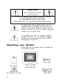
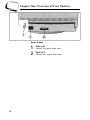
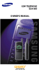
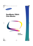
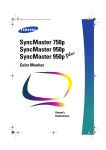
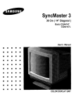
Samsung
SyncMaster 700s
Color Monitor
Owner’s
Instructions
CAUTION
RISK OF ELECTRIC SHOCK
DO NOT OPEN
CAUTION: TO REDUCE THE RISK OF ELECTRIC SHOCK,
DO NOT REMOVE COVER (OR BACK).
NO USER-SERVICEABLE PARTS INSIDE.
REFER SERVICING TO QUALIFIED SERVICE PERSONNEL.
The lightning flash with arrowhead symbol, within an
equilateral triangle, is intended to alert the user to the
presence of uninsulated “dangerous voltage” within the
product’s enclosure that may be of sufficient magnitude to
constitute a risk of electric shock.
The exclamation point within an equilateral triangle is
intended to alert the user to the presence of important
operating and servicing instructions in the literature
accompanying the appliance.
Unpacking your Monitor
Please make sure the following items are included with
your computer monitor:
Power Cable
This Manual
Monitor and Stand
Warranty Card
(Not available in all areas)
ii
Signal Cable
Table of Contents
Preface: Safety Information
Chapter One: Overview of Your Monitor
Front Panel
Rear Panel
Chapter Two: Installation
Connecting Your Monitor to a Computer
Chapter Three: Adjusting Your Monitor
Overview
Direct Access Features
Contrast
Brightness
Control Function Features
Position(H/V) / User or Preset Model
Size( H/V)
Geometric Distortion (G/D)
Color Temperature
Recall
Degauss
PowerSaver
Troubleshooting
Appendix
Specifications
Pin Assignments
Display Modes Timing Chart
FCC Information
IC Compliance Notice
VCCI Information
MPR II Compliance
European Notice
Index
2
3
3
4
5
5
6
6
6
6
6
7
7
8
8
9
9
9
10
11
12
12
13
13
14
16
16
16
16
17
1
Preface: Safety Information
Please read and follow these instructions when connecting and using your
computer monitor.
1
Before connecting the AC power
cord to an outlet, make sure the
voltage designation on your monitor corresponds to the local electrical supply.
2
Never insert anything metallic into
the monitor openings. Doing so
may create the danger of electric
shock.
3
To avoid electric shock, never
touch the inside of the monitor.
Only a qualified technician should
open the monitor’s case.
4
Never use your monitor if the
power cord has been damaged.
Do not allow anything to rest on
the power cord, and keep the cord
away from where people could trip
over it.
5
Be sure to hold the plug, not the
cord, when disconnecting the
monitor from an electric socket.
6
Openings in the monitor cabinet
are provided for ventilation. To
prevent overheating, these openings should not be blocked or covered. Also, avoid using the monitor
on a bed, sofa, rug, or other soft
surface. Doing so may block the
ventilation openings in the bottom
of the cabinet. If you put the monitor in a bookcase or some other
enclosed space, be sure to provide adequate ventilation.
2
7
Put your monitor in a location with
low humidity and a minimum of
dust. Avoid places like damp
basements or dusty hallways.
8
Do not expose the monitor to rain
or use it near water (in kitchens,
next to swimming pools, etc.). If
the monitor accidentally gets wet,
unplug it and contact an authorized dealer immediately. You can
clean the monitor with a damp
cloth when necessary, but be sure
to unplug the monitor first.
9
Place the monitor on a solid surface and treat it carefully. The
screen is made of glass and can
be damaged if dropped or sharply
hit.
Locate your monitor near an easily
AC outlet.
10 accessible
If your monitor does not operate
– in particular, if there
11 normally
are any unusual sounds or smells
coming from it – unplug it immediately and contact an authorized
dealer or service center.
temperatures can cause
12 High
problems. Don’t use your monitor
in direct sunlight, and keep it away
from heaters, stoves, fireplaces,
and other sources of heat.
the monitor when it is
going to be left unused for an
13 Unplug
extended period of time.
Unplug your monitor from the AC
before any service.
14 outlet
Chapter One: Overview of Your Monitor
English
Front Panel
Function control buttons
1
Use these buttons to control the shape of the display
area, and to control the color qualities of the display
image.
2
Brightness
3
Contrast
4
5
Use this rotary control to adjust the overall brightness of the display image.
Use this rotary control to adjust the contrast level of
the display image.
Power indicator
This light glows green during normal operation, and
glows amber when you are making adjustments.
Power button
Use this button to turn the monitor on and off.
3
Chapter One: Overview of Your Monitor
3
Rear Panel
1
2
4
Power port
Connect the power cable here.
Signal port
Connect your signal cable here.
Chapter Two: Installation
English
Connecting Your Monitor
to a Computer
1
2
3
4
5
Connect the signal cable (with the
adapter if necessary) to the video
port on the back of your computer.
This port might be directly
attached to your computer, or it
might be part of a video board,
video card, or graphics card.
6
Connect the power cord for your
monitor to the power port on the
back of the monitor.
7
Plug the power cords of your computer and your monitor into a nearby outlet.
8
Turn on your computer and monitor. If your monitor displays an
image, installation is complete.
Turn off your computer and unplug
its power cord.
Connect the signal cable to the
signal port on the back of your
monitor.
If you are using a Macintosh computer, connect the other end of the
signal cable to a Macintosh
adapter. (The adapter is not included with your monitor. Contact your
dealer for more information.) If you
are using an IBM-compatible computer, skip to step 5.
Follow the instructions included
with your adapter to set the pins
on your adapter, if necessary.
5
Chapter Three: Adjusting Your Monitor
Overview
Your Samsung SyncMaster computer monitor allows you
to easily adjust the characteristics of the image being displayed. All of these adjustments are made using the control buttons on the front of the monitor. While you use
these buttons to adjust the controls, an on-screen menu
shows you their numeric values as they change.
Direct-Access Features
The features described on this page can be accessed
quickly, at the touch of one button.
Contrast
This feature will adjust the monitor’s contrast.
Rotate the rotary control to the right to increase the
contrast between dark colors and light colors, or
move it to the left to decrease the contrast.
Brightness
This feature will adjust the overall brightness of the display
image.
Rotate the rotary control to the right to increase the
level of brightness, or to the left to decrease the
brightness.
6
Chapter Three: Adjusting Your Monitor
Control Function Features
The features described in this section can all be accessed
using your monitor’s control function buttons.
While implementing control functions, the indicator’s color
is orange. However, you cannot adjust the display image
while a control function is disabled (the indicator’s color is
green).
Most features use only one button for access, however
some features require that you push two buttons. Follow
the instructions below to adjust the features.
The monitor will automatically save your changes when
the OSD remains inactive for approximately 8 seconds.
Position (H/V) / User or Preset Mode
First Function: Position (H/V)
Follow these instructions to change the position of the
monitor’s entire display.
1
2
Push this button once to adjust the horizontal and
vertical position (centering) of the display.
Use the 4 and b buttons to change the horizontal
position of the entire display; use the V and A buttons to change the vertical position.
Second Function: User or Preset Modes
Push this button twice to access the user and preset
modes information. The OSD shows the contents of the
user modes and factory timing modes. Use the adjustment
control buttons (V and A) to “page” through the list.
7
Chapter Three: Adjusting Your Monitor
Size (H/V)
Follow these instructions to change the size of the monitor’s entire display.
1
2
Push this button once to adjust the horizontal and
vertical size of the entire display.
Use the 4 and b buttons to change the horizontal
size (width) of the entire display; use the V and A
buttons to change the vertical size (height).
Geometric Distortion (G/D)
First function: Pincushion / Trapezoid
Adjust the pincushion setting when the sides of the display
are bowed in or bowed out.; adjust the trapezoid setting to
equalize the length of the top and bottom edges.
1
2
Push this button once to access the pincushion and
trapezoid functions.
Use the 4 and b buttons to change the pincushion
setting; use the V and A buttons to change the
trapezoid setting.
Second function: Parallelogram/ Tilt
Adjust the parallelogram setting when the display is leaning left or right; adjust the tilt setting when the display area
appears rotated to the left or right.
1
2
8
Push this button twice to access the parallelogram
and tilt functions.
Use the 4 and b buttons to change the parallelogram setting; use the V and A buttons to adjust the
tilt setting.
Chapter Three: Adjusting Your Monitor
COLOR
TEMP.
Color Temperature
Follow these steps to change the color temperature setting. Color Temperature is a measure of the “warmth” of
the image colors.
1
2
Push this button once to access the color temperature function.
Use the V and A buttons to select between the
9300K color and the 6500K color.
Recall
Use this button to return the settings to their original factory settings.
Push and hold in the recall button for several seconds, or until the power indicator LED changes from
orange to green.
After pushing this button, a green LED indicates that the
factory settings for the current video signal timing have
been recalled. The OSD shows the progress of the recall
function.
Note : This operation resets all of the data in the user
memory area for the current timing signal.
Degauss
The Degauss feature will remove any color impurity
caused by magnetic fields. Do not use the Degauss feature
more than once within a 30-minute period.
Push the button once to activate the degaussing circuit. The monitor may buzz momentarily, the image
colors may change and the image will jiggle for a few
seconds. These effects are normal.
The degaussing circuit automatically turns itself off after a
few seconds.
WARNING : Don’t push and hold the degauss button for
longer than 5 seconds. If you do, this operation resets all of
the data in the user memory area. If this occurs, you must
remake your user adjustments.
9
Chapter Three: Adjusting Your Monitor
PowerSaver
This monitor has a built-in power management system
called PowerSaver. This system saves energy by switching
your monitor into a low-power mode when it has not been
used for a certain amount of time. The available modes
are “On,” “Standby,” “Suspend,” and “Off.”
This system operates with a VESA DPMS compliant video
card installed in your computer. You use a software utility
installed on your computer to set up this feature. See the
table below for details.
State
Power Saving function mode EPA/NUTEK
Power-off Mode
Standby mode
Suspend mode
Position A1
Position A2
Normal
Operation
Horizontal Sync Active
Vertical Sync
Active
Video
Active
Inactive
Active
Blanked
Active
Inactive
Blanked
Inactive
Inactive
Blanked
Power
Indicator
Green
Amber
Amber/Green
Blinking
Amber
Blinking
Power
Consumption
1OOW (max.)
90W (nominal)
55W (nominal)
Less than 15W
Less than 8W
NOTE: This monitor automatically returns to normal operation when horizontal and vertical sync return. This occurs
when you move the computer’s mouse or press a key on
the keyboard.
This monitor is EPA Energy Star compliant and NUTEK
compliant when used with a computer equipped with VESA
DPMS functionality. If your computer system cannot support a display power management function, you can purchase an optional DPMS software program to enable the
power saving function. Please contact Samsung or your
dealer for more information.
For energy conservation, turn your monitor OFF when it is
not needed, or when leaving it unattended for long periods.
10
Chapter Three: Adjusting Your Monitor
Troubleshooting
Before calling for service, check the information in this
section to see if you can remedy any problems yourself.
If you do need assistance, please call the phone number
on the warranty card, the phone number on the back cover
of this manual, or contact your dealer.
There is no screen image.
l Check to see that both the monitor and the computer
are plugged in and turned on.
“Check Signal Cable” appears
l Check the signal cable connection between the computer and the monitor.
The image is too light or too dark.
l Adjust the Brightness or Contrast settings.
The image is too large or too small.
l Adjust the Size settings.
The colors are distorted with dark or
shadowed areas.
l Activate the Degauss feature.
l Adjust the Color Temperature settings.
The power indicator is amber,
amber/green, or blinking.
l The monitor is using its power management system.
Check the power management utility on your
computer.
11
/Option ARAS
Appendix
Specifications
Picture Tube
43 cm (17") full square type [40 cm (15.7") viewable]
Flat face 90° deflection
0.28 Dot pitch
Silica coated with anti electrostatic
Medium short persistence phosphor
Synchronization
Horizontal: 30 kHz to 69 kHz (automatic)
Vertical: 50 Hz to 160 Hz (automatic)
Display Color
Unlimited colors
Maximum Resolution
Horizontal: 1280 dots
Vertical: 1024 lines
Active Display
Horizontal: 306 ± 3 mm (12.05"+ 0.12")
Vertical: 230 ± 3 mm (9.06"+ 0.12”)
(Active display size is dependent upon signal timing)
Input Signal, Terminated
Analog 0.714 Vpp positive at 75 Ω
Separate sync: TTL level, positive or negative
Composite sync: TTL level, positive or negative
Maximum Pixel Clock
110MHz
Power Supply
AC 100-240 Volt ± 10%, 60 Hz/50 Hz ± 3 Hz
Power Consumption
100 Watt maximum
Dimensions/Weight
Unit:
424 x 446 x 425 mm; 19 Kg
16.7 x 17.6 x16.7 in (W x D x H); 41.9 Ibs.
Carton: 545 x 554 x 538 mm; 22 kg
21.5 x 21.9 x 21.2 in (W x D x H); 48.5 Ibs.
(All measurements approximate.)
Environmental Considerations
Operating Temperature: 32°F to 104°F (0°C to 40°C)
Humidity: 10% to 80%
l Storage Temperature: -4°F to 113°F (-20°C to 45°C)
Humidity: 5% to 95%
l
NOTE: Design and specifications are subject to change without prior notice.
12
Appendix
Pin Assignments
Sync Type
Pin No.
1
2
3
4
5
6
7
8
9
10
11
12
13
14
15
15 Pin Side of the Signal Cable (Figure 1)
Separate
Red
Green
Blue
GND
DDC Return
GND-R
GND-G
GND-B
Reserved
GND-Sync/Self-Raster
GND
DDC Data
H-Sync
V-Sync
DDC Clock
Cable Adapter (Figure 2
Composite
Red
Green
Blue
GND
DDC Return
GND-R
GND-G
GND-B
Reserved
GND-Sync/Self-Raster
GND
DDC Data
H/V-Sync
Not Used
DDC Clock
Apple MAC II
GND-R
Red
H/V Sync
Sense 0
Green
GND-G
Sense 1
Reserved
Blue
Sense 2
GND
V-Sync
GND-B
GND
H-Sync
Figure 2 : Male Type
Figure 1 : Male Type
Display Modes Timing Chart
Display Mode
IBM, VGA2, 720 x 400
IBM, VGA3, 640 x 480
VESA, 640 x 480
VESA, 800 x 600
VESA, 800 x 600
VESA, 1024 x 768
VESA, 1024 x 768
Horizontal
Vertical
Frequency (kHz) Frequency (Hz)
31.469
31.469
37.500
46.875
53.674
60.023
68.677
70.087
59.940
75.000
75.000
85.061
75.029
84.997
Pixel
Sync Polarity
Clock (MHz)
(H/V)
28.322
25.175
31.500
49.500
56.250
78.750
94.500
–/+
–/–
–/–
+/+
+/+
+/+
+/+
13
Appendix
FCC Information
User Instructions
The Federal Communications Commission Radio Frequency
Interference Statement includes the following warning:
NOTE: This equipment has been tested and found to comply with the limits for a Class B digital device, pursuant to
Part 15 of the FCC Rules. These limits are designed to provide reasonable protection against harmful interference in
a residential installation. This equipment generates, uses,
and can radiate radio frequency energy and, if not installed
and used in accordance with the instructions, may cause
harmful interference to radio communications. However,
there is no guarantee that interference will not occur in a
particular installation.
If this equipment does cause harmful interference to radio
or television receptions, which can be determined by turning the equipment off and on, the user is encouraged to try
to correct the interference by one or more of the following
measures:
l Reorient or relocate the receiving antenna.
l Increase the separation between the equipment and
receiver.
l Connect the equipment into an outlet on a circuit different from that to which the receiver is connected.
l Consult the dealer or an experienced radio/TV technician for help.
14
Appendix
User Information
Changes or modifications not expressly approved by the
party responsible for compliance could void the user’s
authority to operate the equipment.
If necessary, consult your dealer or an experienced
radio/television technician for additional suggestions. You
may find the booklet called How to Identify and Resolve
Radio/TV Interference Problems helpful. This booklet was
prepared by the Federal Communications Commission. It is
available from the U.S. Government Printing Office,
Washington, DC 20402, Stock Number 004-000-00345-4.
Warning
User must use shielded signal interface cables to maintain
FCC compliance for the product.
Provided with this monitor is a detachable power supply
cord with IEC320 style terminations. It may be suitable for
connection to any UL Listed personal computer with similar configuration. Before making the connection, make
sure the voltage rating of the computer convenience outlet
is the same as the monitor and that the ampere rating of
the computer convenience outlet is equal to or exceeds
the monitor voltage rating.
For 120 Volt applications, use only UL Listed detachable
power cord with NEMA configuration 5-15P type (parallel
blades) plug cap. For 240 Volt applications use only UL
Listed Detachable power supply cord with NEMA configuration 6015P type (tandem blades) plug cap.
15
Appendix
IC Compliance Notice
This Class B digital apparatus meets all requirements of
the Canadian Interference-Causing Equipment Regulations
of ICES-003.
VCCI Information
This equipment is in the 2nd Class category (information
equipment to be used in a residential area or an adjacent
area thereto) and conforms to the standards set by the
Voluntary Control Council For Interference by Data
Processing Equipment and Electronic Office Machines
aimed at preventing radio interference in such residential
area. When used near a radio or TV receiver, it may
become the cause of radio interference. Read the instructions for correct handling.
MPR II Compliance
The SyncMaster 700s monitor complies with SWEDAC
(MPR II) recommendations for reduced electric and magnetic fields.
European Notice
Manufacturer: Samsung Electronics Co., Ltd.
Model Number: SyncMaster 700s
Products with the CE Marking comply with both the EMC
Directive (89/336/EEC), (92/31/EEC), (93/68/EEC) and the Low
Voltage Directive (73/23/EEC) issued by the Commission of
the European Community.
Compliance with these directives implies conformity to the
following European Norms:
l EN55022 (CISPR 22) – Radio Frequency Interference
l EN50082-1 : 1992 – Electromagnetic Immunity
l EN60555-2 (IEC555-2) – Power Line Harmonics
l EN60555-3 (IEC555-3) -Voltage Fluctuations
l EN60950 (IEC950) – Product Safety
16
Index
A
5
Adapter
B
3, 6
Brightness
C
9
Color temperature
Connecting your monitor to a computer 5
3, 6
Contrast
D
9
Degauss
13
Display modes timing chart
E
16
European notice
F
14
FCC information
3
Front panel
3
Function control buttons
G
8
Geometric distortion
I
16
IC compliance notice
5
Installation
M
5
Macintosh
ii
Manual
16
MPR II compliance
P
8
Paralleolgram
13
Pin assignments
8
Pincushion
7
Position
3
Power button
ii
Power cable
3
Power indicator
4
Power port
10
Powersaver
7
Preset mode
R
4
Rear panel
9
Recall
S
Safety
Signal cable
Signal port
Size
Specifications
Stand
T
Tilt
Trapzoid
Troubleshooting
U
User mode
V
VCCI information
W
Warranty card
2
ii
4
8
12
ii
8
8
11
7
16
ii
17
U.S.A. :
Samsung Electronics America (SEA)
One Samsung Place
Ledgewood, NJ 07852
Tel. : 1-800-SAMSUNG (1-800-726-7864)
Fax-on-Demand for product information :
1-800-229-2239
CANADA :
Samsung Electronics Canada Inc.
7037 Financial Drive
Mississauga, Ontario L5N 6R3
Tel. : 1-800-SAMSUNG (1-800-726-7864)
Fax. : (416) 542-1199
GERMANY:
Samsung Electronics GmbH
lnfoline
Tel. : 0180-5121213
Fax. : 0180-5121214
AUSTRALIA :
Samsung Electronics Australia Pty Ltd.
Unit G, 10-16 South Street,
Rydalmere, N.S.W. 2116
P.O. BOX 368
Tel. : (02) 638 5200
ITALIA :
Samsung Electronics ltalia SpA
Via C. Donat Cattin,
5-20063 Cernusco sul Naviglio (Mi)
Tel. : 167-010740
PANAMA :
Servicios Samsung (Zona Libre), S.A.
50 and 61 Streets Sta, Cecilia
Bdl. Don Camilo, Panama City
Tel. : (507) 264-0195 or 269-5571
Fax : (507) 269-5568
CODE NO.:BH68-60709A (Rev. 0.2)
ESPAÑA :
Samsung Electrónics Comercial Ibérica, S.A.
Ciencies, 55-65 (Polígono Pedrosa) 08908
Hospitalet de Llobregat (Barcelona)
Tel. : (93) 261 67 00
Fax. : (93) 261 67 50
UK:
Samsung Electronics (UK) Ltd.
Samsung House, 225 Hook Rise South
Surbiton, Surrey KT6 7LD
Tel. : (0181) 391 0168
Fax. : (0181) 397 9949
<European Service Center & National
Service>
Stafford Park 12 Telford, Shropshire, TF3 3BJ
Tel. : (01952) 292 262
Fax. : (01952) 292 033
THAILAND :
Samsung Service Center
729-729/1 JSP Tower Rachadapisek RD.,
Bangpongpang, Yannawa, Bangkok 10120
Tel : (662) 2954508-14
Fax : (662) 2954267
SOUTH AFRICA :
Samsung Electronics South Africa
Somerset Office Park 5 Libertas Road
Bryanston, South Africa
Tel : (27)-11-463-5678
Fax : (27)-11-463-5215
BRASIL :
Samsung Eletrônica da Amazonia Ltda.
R. Prof. Manoelito de Ornellas, 303-2° Andar
Chácara Sto. Antônio • cep : 04719-040
São Paulo • SP
Tel. : (011) 541-8500
Fax : (011) 523-3995, 522-0726
Printed on recyclable paper