1
Bosch Video Management System
MBV-BPRO-40
en
Configuration Manual
Bosch Video Management System
Table of Contents | en
3
Table of contents
1
Using the Help
11
1.1
Finding information
11
1.2
Printing the Help
11
2
Introduction
13
3
System overview
15
3.1
Hardware requirements
15
3.2
Software requirements
15
3.3
License requirements
15
4
Network configuration
16
4.1
Installing hardware
17
5
Getting started
18
5.1
Installing the software modules
18
5.2
Activating the software licenses
18
5.3
Starting Configuration Client
19
5.4
Configuring the language of Configuration Client
19
5.5
Configuring the language of Operator Client
19
5.6
Adding a new license
19
5.7
Working offline
20
6
Configuring devices
21
6.1
Adding multiple Management Server computers
23
6.2
Detecting NVRs, their recorded encoders, and decoders
24
6.3
Detecting VRM devices
25
6.4
Configuring NVRs
25
6.4.1
Configuring a Primary NVR
26
6.4.2
Switching an NVR to a Failover NVR
27
6.4.3
Switching an NVR to a Redundant NVR
27
6.4.4
Configuring a Failover NVR
27
6.4.5
Configuring a Redundant NVR
27
6.4.6
Assigning NVRs to Failover NVRs
28
6.4.7
Assigning NVRs to a Redundant NVR
28
6.4.8
Displaying information on an NVR
29
6.4.9
Changing the network address of an NVR / Failover NVR / Redundant NVR
29
6.5
Adding a device
29
6.6
Configuring an encoder / decoder
32
6.7
Configuring a decoder for use with a CCTV keyboard
32
6.8
Configuring multiple encoders / decoders
33
6.9
Configuring a DiBos system
34
6.10
Configuring a Bosch Allegiant device
34
6.11
Configuring a startup Command Script
34
6.12
Changing the network address of a workstation
34
6.13
Enabling Forensic Search on a workstation
35
6.14
Assigning an analog monitor group to a workstation
35
6.15
Configuring an analog monitor group
35
6.16
Adding a monitor wall
36
6.17
Configuring a communication device
36
6.18
Configuring a peripheral device
36
6.19
Configuring network monitoring
36
Bosch Sicherheitssysteme GmbH
Configuration Manual
2012.07 | V1 | Configuration Client
4
en | Table of Contents
Bosch Video Management System
6.20
Configuring a CCTV keyboard (workstation)
37
6.21
Configuring a CCTV keyboard (decoder)
37
6.22
Configuring an I/O module
37
6.23
Configuring an Allegiant CCL emulation
38
6.24
Adding a mobile video service
38
6.25
Adding a VRM device with iSCSI storage
38
6.26
Configuring an iSCSI device
38
6.27
Adding a LUN
40
6.28
Formatting a LUN
40
6.29
Adding a local storage or live only device
40
6.30
Adding a Video Streaming Gateway device
41
6.31
Adding a Bosch camera to a VSG
42
6.32
Adding an ONVIF camera to a VSG
42
6.33
Configuring multicast for VSG
43
6.34
Switching on VSG recording
43
7
Configuring the structure
44
7.1
Configuring the Logical Tree
44
7.2
Adding a device to the Logical Tree
44
7.3
Removing a tree item
44
7.4
Managing resource files
44
7.5
Adding a Command Script
46
7.6
Managing pre-configured camera sequences
46
7.7
Adding a camera sequence
47
7.8
Adding a folder
47
7.9
Adding a map
48
7.10
Adding a link to another map
48
7.11
Assigning a map to a folder
48
7.12
Managing devices on a map
49
7.13
Adding a document
49
8
Configuring schedules
51
8.1
Configuring a Recording Schedule
51
8.2
Adding a Task Schedule
52
8.3
Configuring a standard Task Schedule
52
8.4
Configuring a recurring Task Schedule
52
8.5
Removing a Task Schedule
53
8.6
Adding holidays and exception days
53
8.7
Removing holidays and exception days
54
8.8
Renaming a schedule
54
9
Configuring cameras and recording settings
55
9.1
Copying and pasting in tables
55
9.2
Configuring stream quality settings
56
9.3
Configuring camera properties
56
9.4
Configuring recording settings (only VRM and Local Storage)
57
9.5
Configuring recording settings (only NVR)
57
9.6
Configuring port settings
58
9.7
Configuring PTZ camera settings
59
10
Configuring events and alarms
60
10.1
Copying and pasting in tables
61
10.2
Removing a table row
61
2012.07 | V1 | Configuration Client
Configuration Manual
Bosch Sicherheitssysteme GmbH
Bosch Video Management System
Table of Contents | en
5
10.3
Managing resource files
61
10.4
Configuring an event
61
10.5
Duplicating an event
62
10.6
Logging user events
62
10.7
Configuring user event buttons
62
10.8
Creating a Compound Event
63
10.9
Editing a Compound Event
64
10.10
Configuring an alarm
64
10.11
Configuring settings for all alarms
65
11
Configuring Command Scripts
66
11.1
Managing Command Scripts
66
11.2
Configuring a Command Script to be started automatically
67
11.3
Importing a Command Script
67
11.4
Exporting a Command Script
67
11.5
Configuring a startup Command Script
67
12
Configuring users, permissions and Enterprise Access
69
12.1
Creating a user
69
12.2
Creating a group or account
70
12.3
Creating a dual authorization group
71
12.4
Configuring LDAP settings
72
12.5
Associating an LDAP group
72
12.6
Scheduling user logon permission
73
12.7
Configuring operating permissions
73
12.8
Configuring user interface settings
74
12.9
Configuring permissions for Logical Tree
74
12.10
Configuring permissions for events and alarms
75
12.11
Configuring camera permissions
75
12.12
Configuring decoder permissions
75
12.13
Configuring various priorities
76
12.14
Copying user group permissions
76
13
Managing configuration data
78
13.1
Activating the working configuration
78
13.2
Activating a configuration
79
13.3
Exporting configuration data
79
13.4
Exporting configuration data to OPC
79
14
Configuration examples
81
14.1
Creating an Enterprise System
81
14.1.1
Adding multiple Management Server computers
81
14.1.2
Creating an Enterprise User Group
83
14.1.3
Creating an Enterprise Account
84
14.2
Adding a Bosch ATM/POS bridge
86
14.3
Adding a Bosch Allegiant input alarm
87
14.4
Adding and configuring 2 Dinion IP cameras with VRM recording
87
15
Global Configuration Client windows
89
15.1
Configuration window
89
15.2
Menu commands
90
15.3
Activation Manager dialog box
91
15.4
Activate Configuration dialog box
92
15.5
License Manager dialog box
92
Bosch Sicherheitssysteme GmbH
Configuration Manual
2012.07 | V1 | Configuration Client
6
en | Table of Contents
Bosch Video Management System
15.6
License Activation dialog box
92
15.7
Alarm Settings dialog box
93
15.8
Stream Quality Settings dialog box
93
15.9
Options dialog box
94
16
Devices page
95
16.1
Server List page
96
16.1.1
Add Server dialog box
96
16.2
Initial Device Scan dialog box
97
16.3
NVR & Decoder Scan dialog box
97
16.4
Bosch VMS Scan Wizard
97
16.5
Failover NVR Manager dialog box
98
16.6
IP Device Configuration dialog box
98
16.7
Set IP Addresses dialog box
99
16.8
Set Display Names dialog box
99
16.9
NVRs / Failover NVRs / Redundant NVRs page
16.9.1
Global Settings page
100
16.9.2
Disk Storage page
100
16.9.3
Camera Storage page
101
16.9.4
Assigned NVRs page
102
16.9.5
Assigned NVR page
102
16.9.6
Add Network Path dialog box
103
16.9.7
Add Local NVR Drive dialog box
103
16.10
Vidos NVRs page
103
16.11
DiBos page
103
16.11.1
Add DiBos System dialog box
104
16.11.2
Settings page
104
16.11.3
Cameras page
104
16.11.4
Inputs page
104
16.11.5
Relays page
104
16.12
Matrix Switches page
105
16.12.1
Connection page
105
16.12.2
Cameras page
105
16.12.3
Outputs page
105
16.12.4
Inputs page
106
16.13
Workstation page
106
16.13.1
Settings page
107
16.13.2
Assigned Analog Monitor Groups page
108
16.14
Decoders page
108
16.15
Analog Monitor Groups page
108
16.15.1
Settings page
108
16.15.2
Advanced Configuration page
109
16.16
Monitor Wall page
110
16.16.1
Add Monitor Wall dialog box
110
16.17
Communication Devices page
111
99
16.17.1
E-mail/SMTP Server dialog box
111
16.17.2
Add SMS Device dialog box
111
16.17.3
SMTP Server page
111
16.17.4
Send Test E-mail dialog box
112
16.17.5
GSM Settings / SMSC Settings page
112
2012.07 | V1 | Configuration Client
Configuration Manual
Bosch Sicherheitssysteme GmbH
Bosch Video Management System
Table of Contents | en
7
16.18
POS + ATM page
113
16.18.1
Add Bosch ATM/POS-Bridge dialog box
113
16.18.2
Bosch ATM/POS-Bridge page
114
16.18.3
Inputs page
114
16.18.4
ATM Settings page
114
16.19
Virtual Inputs page
114
16.19.1
Add Virtual Inputs dialog box
115
16.20
SNMP page
115
16.20.1
Add SNMP dialog box
115
16.20.2
SNMP Trap Receiver page
115
16.20.3
SNMP Trap Logger dialog box
116
16.21
CCTV Keyboards page
116
16.22
I/O Modules page
117
16.22.1
ADAM page
117
16.22.2
Inputs page
117
16.22.3
Relays page
118
16.23
Allegiant CCL Emulation page
118
16.24
Mobile Video Service page
119
16.24.1
Add Mobile Video Service dialog box
119
16.25
VRM Devices page
119
16.26
VRM Settings page
120
16.26.1
Advanced page
121
16.26.2
SNMP page
121
16.26.3
iSCSI System Access page
121
16.26.4
Default Configuration page
122
16.26.5
Load Balancing page
122
16.26.6
iqn-Mapper dialog box
123
16.26.7
LUNs page
123
16.26.8
Add LUN dialog box
123
16.27
Video Streaming Gateway device page
123
16.28
Assignment tab (Video Streaming Gateway)
124
16.29
Add/Edit dialog box (Video Streaming Gateway)
124
16.30
Recording profiles tab (Video Streaming Gateway)
126
16.31
Multicast tabs (Video Streaming Gateway)
126
16.32
Advanced tab (Video Streaming Gateway)
126
16.33
Live Only page
127
16.33.1
ONVIF Encoder page
127
16.33.2
Add ONVIF dialog box
127
16.34
Local Storage page
127
17
Encoders / Decoders page
128
17.1
Main Settings > Unit Access page
128
17.1.1
Identification / Camera identification
128
17.1.2
Camera name
129
17.1.3
Version information
129
17.2
Main Settings > Date/Time page
129
17.3
Advanced Settings > Video Input page
129
17.3.1
Picture settings
129
17.3.2
Input termination
130
17.3.3
Source type
130
Bosch Sicherheitssysteme GmbH
Configuration Manual
2012.07 | V1 | Configuration Client
8
en | Table of Contents
Bosch Video Management System
17.4
Advanced Settings > Recording Management page
130
17.5
Advanced Settings > Recording preferences page
131
17.6
Advanced Settings > VCA page
132
17.6.1
Motion detector (MOTION+ only)
133
17.6.2
Select Area dialog box
133
17.6.3
Tamper detection
134
17.7
Advanced Settings > Audio Alarm page
135
17.8
Advanced Settings > Alarm Rules page
135
17.9
Camera > Display Stamping page
136
17.10
Camera > Privacy Masks page
137
17.11
Camera > Camera page
138
17.12
Camera > Lens page
139
17.12.1
Focus
139
17.12.2
Iris
140
17.12.3
Zoom
140
17.13
Camera > PTZ page
140
17.14
Camera > Prepositions and Tours page
141
17.15
Camera > Sectors page
141
17.16
Camera > Installer Menu page
141
17.17
Camera > Misc page
142
17.18
Camera > Logs page
142
17.19
Camera > Audio page
142
17.20
Interfaces > Relay page
143
17.21
Interfaces > Periphery page
143
17.21.1
COM1
143
17.22
Network > Network Access page
144
17.23
Network > Advanced page
145
17.23.1
SNMP
145
17.23.2
802.1x
145
17.23.3
Encryption
146
17.23.4
RTSP
146
17.23.5
NTCIP
146
17.23.6
UPnP
146
17.23.7
TCP metadata input
146
17.24
Network > Multicast page
146
17.25
Network > FTP Posting page
147
17.25.1
JPEG posting
147
17.25.2
FTP server
148
17.26
Service > Licenses page
148
17.27
Decoder > Decoder page
148
17.27.1
Decoder profile
148
17.27.2
Monitor display
149
18
Maps and Structure page
150
18.1
Resource Manager dialog box
151
18.2
Select Resource dialog box
151
18.3
Sequence Builder dialog box
151
18.4
Add Sequence dialog box
152
18.5
Add Sequence Step dialog box
153
18.6
Add URL dialog box
153
2012.07 | V1 | Configuration Client
Configuration Manual
Bosch Sicherheitssysteme GmbH
Bosch Video Management System
Table of Contents | en
9
18.7
Select Map for Link dialog box
153
19
Schedules page
154
19.1
Recording Schedules page
154
19.2
Task Schedules page
154
20
Cameras and Recording page
156
20.1
Cameras page
156
20.2
Scheduled Recording Settings dialog box (only VRM and Local Storage)
158
20.3
Recording settings pages (NVR only)
159
20.4
Stream Quality Settings dialog box
160
20.5
PTZ Settings dialog box
162
21
Events page
163
21.1
Command Script Editor dialog box
164
21.2
Create Compound Event / Edit Compound Event dialog box
165
21.3
Select Script Language dialog box
165
21.4
Edit Priorities of Event Type dialog box
166
21.5
Select Devices dialog box
166
22
Alarms page
167
22.1
Alarm Settings dialog box
168
22.2
Select Image Pane Content dialog box
168
22.3
Select Resource dialog box
169
22.4
Alarm Options dialog box
169
23
User Groups page
172
23.1
Add New User Group/Account dialog box
173
23.2
User Group Properties page
174
23.3
User Properties page
175
23.4
Add New Dual Authorization Group dialog box
175
23.5
Logon Pair Properties page
176
23.6
Select User Groups dialog box
176
23.7
Camera Permissions page
177
23.8
Control Priorities
178
23.9
Copy User Group Permissions dialog box
178
23.10
Decoder Permissions page
179
23.11
Events and Alarms page
179
23.12
LDAP Server Settings dialog box
179
23.13
Credentials page
181
23.14
Logical Tree page
182
23.15
Operator Features page
182
23.16
Priorities page
184
23.17
User Interface page
184
23.18
Server Access page
185
24
Concepts
187
24.1
Alarm handling
187
24.2
Enterprise System
188
24.2.1
Scenarios
188
24.2.2
Permissions
191
24.2.3
Types of user groups
191
24.2.4
Licensing
191
24.3
Connecting Bosch Allegiant Matrix to Bosch Video Management System
192
24.3.1
Bosch Allegiant Connection Overview
192
Bosch Sicherheitssysteme GmbH
Configuration Manual
2012.07 | V1 | Configuration Client
10
en | Table of Contents
Bosch Video Management System
24.3.2
Configuring the control channel
194
24.3.3
Bosch Allegiant Satellite System Concept
195
24.4
Allegiant CCL commands supported in Bosch VMS
196
24.5
Connecting CCTV keyboard to Bosch Video Management System
198
24.5.1
Scenarios for CCTV keyboard connections
198
24.5.2
Connecting a CCTV keyboard to a decoder
199
24.5.3
Updating CCTV keyboard firmware
200
25
Troubleshooting
202
25.1
Configuring the desired language in Windows
204
25.2
Reestablishing the connection to a CCTV keyboard
204
25.3
Reducing the number of Allegiant cameras
204
25.4
Restoring a system configuration
204
2012.07 | V1 | Configuration Client
Configuration Manual
Bosch Sicherheitssysteme GmbH
Bosch Video Management System
Using the Help | en
11
Using the Help
1
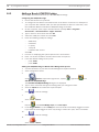
To find out more about how to do something in Bosch Video Management System, access the
online Help using any of the following methods.
To use the Contents, Index, or Search:
4 On the Help menu, click Help. Use the buttons and links to navigate.
To get Help on a window or dialog:
4
On the toolbar, click
.
OR
4 Press F1 for help on any program window or dialog.
1.1
Finding information
You can find information in the Help in several ways.
To find information in the Online Help:
1.
On the Help menu, click Help.
2.
If the left-hand pane is not visible, click the Show button.
3.
In the Help window, do the following:
Click:
To:
Contents
Display the table of contents for the Online Help. Click each book to
display pages that link to topics, and click each page to display the
corresponding topic in the right-hand pane.
Index
Search for specific words or phrases or select from a list of index
keywords. Double-click the keyword to display the corresponding topic
in the right-hand pane.
Search
Locate words or phrases within the content of your topics. Type the
word or phrase in the text field, press ENTER, and select the topic you
want from the list of topics.
Texts of the user interface are marked bold.
4 The arrow invites you to click on the underlined text or to click an item in the application.
4
Click
to get step-by-step instructions
Related Topics
4 Click to display a topic with information on the application window you currently use.
This topic provides information on the application window controls.
Concepts, 187 provides background information on selected issues.
Caution!
Medium risk (without safety alert symbol): Indicates a potentially hazardous situation.
If not avoided, this may result in property damage or risk of damage to the unit.
Cautionary messages should be heeded to help you avoid data loss or damaging the system.
i
1.2
Notice!
This symbol indicates information or a company policy that relates directly or indirectly to the
safety of personnel or protection of property.
Printing the Help
While using the Online Help, you can print topics and information right from the browser
window.
Bosch Sicherheitssysteme GmbH
Configuration Manual
2012.07 | V1 | Configuration Client
12
en | Using the Help
Bosch Video Management System
To print a Help topic:
1.
Right-click in the right pane and select Print.
The Print dialog box opens.
2.
Click Print. The topic is printed to the specified printer.
2012.07 | V1 | Configuration Client
Configuration Manual
Bosch Sicherheitssysteme GmbH
Bosch Video Management System
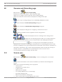
2
Introduction | en
13
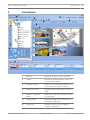
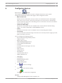
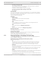
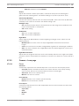
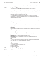
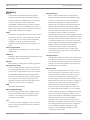
Introduction
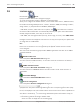
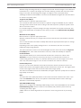
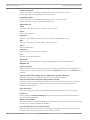
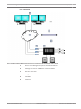
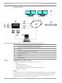
1
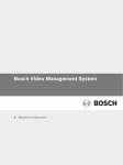
Menu bar
Allows you to select a menu command.
2
Toolbar
Displays the available buttons. Point to an
icon to display a tooltip.
3
Playback controls
Allows you to control instant playback or a
camera sequence or alarm sequence.
5
Performance meter
Displays the CPU usage and the memory
usage.
6
7
Slider for Image pane
Allows you to select the required number
pattern
of Image panes.
Image window
Displays the Image panes. Allows you to
arrange the Image panes.
8
Image pane
Displays a camera, a map, an image, a
document (HTML file).
Bosch Sicherheitssysteme GmbH
Configuration Manual
2012.07 | V1 | Configuration Client
14
en | Introduction
Bosch Video Management System
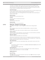
9
Alarm List window
Displays all alarms that the system
generates.
Allows you to accept or clear an alarm or
to start a workflow, for example, by
sending an E-mail to a maintenance
person.
10
11
PTZ Control window
Allows you to control a PTZ camera.
Monitors window (only
Displays the configured analog monitor
available if at least one
groups.
analog monitor group has
Allows you to switch to the next or
been configured)
previous analog monitor group if available.
Logical Tree window
Displays the devices your user group has
access to. Allows you to select a device for
assigning it to an Image pane.
Favorites Tree window
Allows you to organize the devices of the
Logical Tree as required.
Map window
Displays a site map. Allows you to drag the
map to display a particular section of the
map.
This manual guides you through the basic steps of the configuration and operation with Bosch
Video Management System.
For detailed help and step-by-step instructions read the Configuration Manual and the
Operator’s Manual or use the Online Help. You find the manuals as PDF files on your
Setup CD.
Bosch Video Management System integrates digital video, audio and data across any IP
network.
The system consists of the following software modules:
–
Management Server
–
VRM recording (Video Recording Manager)
–
Operator Client (VRM recording / DiBos DVRs / iSCSI recording / VIDOS NVRs / local
recording)
–
Configuration Client
To achieve a running system, you must perform the following tasks:
–
Install services (Management Server and VRM)
–
Install Operator Client and Configuration Client
–
Connect to network
–
Connect devices to network
–
Basic configuration:
–
–
Add devices (e.g. by device scan)
–
Build logical structure
–
Configure schedules, cameras, events, and alarms
–
Configure user groups
Operation
Bosch VMS Archive Player displays exported recordings.
2012.07 | V1 | Configuration Client
Configuration Manual
Bosch Sicherheitssysteme GmbH
Bosch Video Management System
3
System overview | en
15
System overview
If you plan to install and configure Bosch Video Management System, participate in a system
training on Bosch Video Management System.
Refer to the Release Notes of the current Bosch Video Management System version for
supported versions of firmware and hardware and other important information.
See data sheets on Bosch workstations and servers for information on computers where
Bosch Video Management System can be installed.
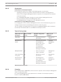
The following software modules can optionally be installed on one PC.
Tasks of the software modules
–
Management Server: Stream management, alarm management, priority management,
Management logbook, user management, device state management. Additional Enterprise
System license: Managing a server list that contains multiple Management Server
computers.
–
VRM: Distributing storage capacities on iSCSI devices to the encoders, while handling
load balancing between multiple iSCSI devices.
Streaming playback video and audio data from iSCSI to Operator Clients.
–
MVS: Provides a transcoding service that adapts the video stream from a camera
configured in Bosch Video Management System to the available network bandwidth. This
enables mobile video clients like an iPhone to receive live or playback video data via
unreliable network connections with limited bandwidth. Not supported on Windows XP.
–
Configuration Client: System configuration and administration for Operator Client.
–
Operator Client: Live monitoring, storage retrieval and playback, alarm and accessing
multiple Management Server computers simultaneously.
3.1
Hardware requirements
See the data sheet for Bosch Video Management System. Data sheets for platform PCs are
also available.
3.2
Software requirements
See the data sheet for Bosch Video Management System.
Bosch Video Management System must not be installed on a computer where you want to
install Bosch VMS Archive Player.
3.3
License requirements
See the data sheet for Bosch Video Management System for the available licenses.
Bosch Sicherheitssysteme GmbH
Configuration Manual
2012.07 | V1 | Configuration Client
16
en | Network configuration
4
Bosch Video Management System
Network configuration
Caution!
!
Do not connect a device to more than one Bosch Video Management System! This can lead to
recording gaps and other undesired effects.
You can connect the following hardware to Bosch Video Management System:
–
Mobile video clients like iPhone or iPad via DynDNS
–
Various IP cameras. encoders and ONVIF cameras (live only or via Video Streaming
Gateway)
Connected via network
–
Live only encoders with local storage
–
iSCSI storage devices
–
VIDOS NVR computer
Connected via network
Connected via network
Connected via network
–
Analog cameras
Connected to encoders, DiBos / Bosch Recording Station
–
Decoders
–
Analog monitors
Connected via network
Connected to a decoder, to a Bosch Allegiant matrix, to a Bosch Video Management
System Client workstation
–
DiBos / Bosch Recording Station (see the data sheet for Bosch Video Management
System for supported versions)
Connected via network
–
Bosch Allegiant matrix (Firmware version: 8.75 or greater, MCS version: 2.80 or greater)
Connected to a COM port of the Management Server or to a remote computer and to an
IP encoder on the network.
–
CCTV keyboard
Connected to the COM port of an Bosch Video Management System workstation
(Firmware version: 1.82 or greater) or to a hardware decoder (VIP XD).
If you connect the keyboard to a workstation, the user can control the complete system
with the keyboard. If you connect the keyboard to a VIP XD decoder, the user can only
control analog monitors with the keyboard.
Only the Bosch IntuiKey Digital Keyboard is supported.
–
SMS device
Connected to a COM port of the Management Server
–
SMTP E-mail server
Connected via network
–
POS
Connected via network
–
ATM
Connected via network
–
Network monitoring device
Connected via network
–
I/O modules
Connected via network
2012.07 | V1 | Configuration Client
Configuration Manual
Bosch Sicherheitssysteme GmbH
Bosch Video Management System
Network configuration | en
17
Only ADAM devices are supported.
All devices connected via network are connected to a switch. The computers of the Bosch
Video Management System are also connected to this device.
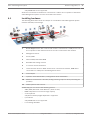
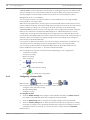
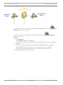
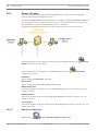
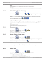
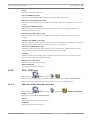
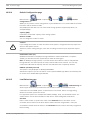
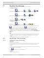
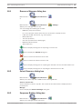
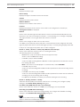
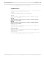
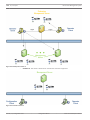
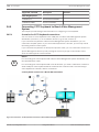
4.1
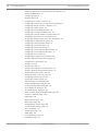
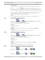
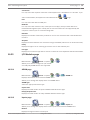
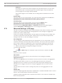
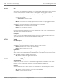
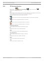
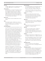
Installing hardware
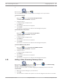
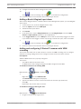
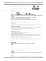
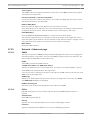
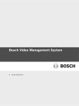
The following illustration shows an example of a small Bosch Video Management System
network with NVR / DVR storage:
Bosch Allegiant matrix with cameras and monitor: Connected to a COM port of one of
1
the computers of the network and to IP encoders connected to the network
2
Management Server
3
Primary NVR
4
Failover NVR, Redundant NVR
5
Encoders with analog cameras
6
IP cameras and IP AutoDomes
7
Communication devices: SMTP E-mail server connected to network, GSM device
connected to a COM port of the Management Server
8
Virtual inputs
9
Operator Client workstations, Configuration Client workstation
10
Monitors connected to a decoder (analog monitor groups for alarm processing are
possible)
11
DiBos Systems with cameras
Additionally you can connect the following devices:
–
ATM / POS (Automatic Teller Machine / Point of Sale)
–
RAID subsystems to increase storage capacity
–
CCTV keyboard
Only Bosch IntuiKey Digital Keyboard is supported.
–
I/O modules
Only ADAM devices are supported.
–
Local storage encoders
Bosch Sicherheitssysteme GmbH
Configuration Manual
2012.07 | V1 | Configuration Client
18
5
en | Getting started
Bosch Video Management System
Getting started
This chapter provides information on how to get started with Bosch Video Management
System and with Bosch VMS Archive Player
5.1
Installing the software modules
Caution!
Do not install DiBos Web client on any Bosch VMS computer.
Install every software module on the computer that is supposed to be used for this module.
To install:
1.
Insert the product CD-ROM.
2.
Start setup.exe or start the Bosch Video Management System Setup on the Welcome
screen.
5.2
3.
In the next dialog box, select the modules to be installed on this computer.
4.
Follow the instructions on the screen.
Activating the software licenses
Main window
When you install Bosch Video Management System for the first time, you must activate the
licenses for the software packages that you have ordered, including the base package and any
expansions and/or optional features.
To obtain the Activation Key for a license, you need the Authorization Number. This number is
included in your product box.
With a Bundle Information file you can ease the process of activating.
Caution!
The computer signature is used for licensing. This computer signature can change after exchanging hardware on the Management Server computer. When the computer signature is
changed, the license for the base package becomes invalid.
To avoid licensing problems, finish the hardware and software configuration before you generate the computer signature.
The following hardware changes can make the base license invalid:
Exchanging the network interface card.
Adding a VMWare or VPN virtual network interface.
Adding or activating a WLAN network interface.
Switchover of a Stratus server mainboard without teaming settings.
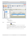
To activate the software:
1.
Start Configuration Client.
2.
On the Tools menu, click License Manager....
3.
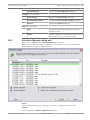
Click to check the boxes for the software package, the features, and the expansions that
The License Manager dialog box is displayed.
you want to activate. For the expansions, enter the number of licenses.
If you have received a Bundle Information file, click Import Bundle Info to import it.
4.
Click Activate.
The License Activation dialog box is displayed.
5.
Write down the computer signature or copy and paste it into a text file.
6.
On a computer with Internet access, enter the following URL into your browser:
https://activation.boschsecurity.com
If you do not have an account to access the Bosch License Activation Center, either
2012.07 | V1 | Configuration Client
Configuration Manual
Bosch Sicherheitssysteme GmbH
Bosch Video Management System
Getting started | en
19
create a new account (recommended) or click the link to activate a new license without
logging on. If you create an account and log on before activating, the License Manager
keeps track of your activations. You can then review this at any time.
Follow the instructions to obtain the License Activation Key.
7.
Return to the Bosch Video Management System software. In the License Activation
dialog box, type the License Activation Key obtained from the License Manager and click
Activate.
The software package is activated.
5.3
5.4
Starting Configuration Client
Configuring the language of Configuration Client
You configure the language of your Configuration Client independently of the language of your
Windows installation.
To configure the language:
1.
On the Settings menu, click Options....
The Options dialog box is displayed.
2.
In the Language of the Configuration Client: list, select the desired language.
If you select Default system language, the language of your Windows installation is used.
3.
Click OK.
The language is switched after the next restart of the application.
5.5
Configuring the language of Operator Client
You configure the language of your Operator Client independently of the language of your
Windows installation and of your Configuration Client. This step is performed in the
Configuration Client.
To configure the language:
1.
Click User Groups >
2.
. Click the User Group Properties tab.
In the Language: list, select the desired language.
3.
Click
to save the settings.
4.
Click
to activate the configuration.
Restart Operator Client.
5.6
Adding a new license
Main window
Have the Activation Letter at hand that you received from Bosch.
To add a new license:
1.
On the Tools menu, click License Manager....
The License Manager dialog box is displayed.
2.
Select the software package that you want to activate.
3.
Click Activate.
4.
Type the License Activation Key that you find in the Activation Letter.
5.
Click Activate.
The License Activation dialog box is displayed.
The software package is activated.
6.
Repeat this procedure for each software package that you want to activate.
Bosch Sicherheitssysteme GmbH
Configuration Manual
2012.07 | V1 | Configuration Client
20
5.7
en | Getting started
Bosch Video Management System
Working offline
When Operator Client is disconnected from a Management Server, a respective overlay icon is
displayed in the Logical Tree on the disconnected Management Server. You can continue
working with Operator Client even if the disconnection lasts longer, but some functions are
not available.
If the connection to the Management Server is reestablished, a respective overlay icon is
displayed.
If a new configuration on a Management Server has been activated, a respective icon is
displayed in the Logical Tree on the icon of the affected Management Server and a dialog box
is displayed for some seconds. Accept or refuse the new configuration.
If your Operator Client instance is scheduled to log off at a specific point in time, this logoff
occurs even when the connection to the Management Server is not reestablished at this point
in time.
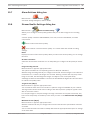
When disconnected from a Management Server, all devices are indicated with the
icon. The
state overlay of a device in the Logical Tree or on a map when Operator Client is disconnected
from the Management Server
The following functions are not available in Operator Client when disconnected from the
Management Server for this connection:
–
Handling alarms, Alarm List
–
Indication of recording
–
Indication of state changes
–
PTZ control locking
–
Analog monitor group
–
Scripts
2012.07 | V1 | Configuration Client
Configuration Manual
Bosch Sicherheitssysteme GmbH
Bosch Video Management System
6
Configuring devices | en
21
Configuring devices
Main window >
Devices
This chapter provides information on how to configure the devices in your system.
Changing the Device Tree impacts other pages of the Configuration Client:
–
Maps and Structure
With the devices of the Device Tree you create a user defined structure called Logical
Tree. Hence, if you remove a device from the Device Tree, this device is automatically
removed from the Logical Tree. But adding a device to the Device Tree does not add this
device to the Logical Tree.
–
Cameras and Recording
All cameras of the Device Tree are available in the Camera Table and the Recording
Tables. You cannot modify DiBos or Bosch Allegiant cameras.
–
Events
All devices of the Device Tree are available in the corresponding Event Tables.
–
User Groups
You can reduce the functional range of the devices on several permission pages (per user
group or Enterprise Account).
You can configure the following devices:
–
Bosch Video Streaming Gateway devices
–
ONVIF encoders
–
Mobile video services
–
Video Recording Manager devices
–
Primary NVR and Failover NVR
–
Encoders
–
Encoders with local storage or live only
–
Decoders
–
DiBos systems
–
Analog matrices
–
Workstations
–
Communication devices
–
ATM and POS devices
–
Virtual inputs
–
I/O modules
–
Network monitoring system
–
CCTV keyboard
–
Analog monitor groups
1.
Click
to save the settings.
Click
to undo the last setting.
2.
3.
Click
to activate the configuration.
See also
–
Adding multiple Management Server computers, 23
Bosch Sicherheitssysteme GmbH
Configuration Manual
2012.07 | V1 | Configuration Client
22
en | Configuring devices
Bosch Video Management System
–
Detecting NVRs, their recorded encoders, and decoders, 24
–
Detecting VRM devices, 25
–
Configuring NVRs, 25
–
Adding a device, 29
–
Configuring an encoder / decoder, 32
–
Configuring a decoder for use with a CCTV keyboard, 32
–
Configuring multiple encoders / decoders, 33
–
Configuring a DiBos system, 34
–
Configuring a Bosch Allegiant device, 34
–
Configuring a startup Command Script, 34
–
Changing the network address of a workstation, 34
–
Enabling Forensic Search on a workstation, 35
–
Assigning an analog monitor group to a workstation, 35
–
Configuring an analog monitor group, 35
–
Configuring a communication device, 36
–
Configuring a peripheral device, 36
–
Configuring network monitoring, 36
–
Configuring a CCTV keyboard (workstation), 37
–
Configuring a CCTV keyboard (decoder), 37
–
Configuring an I/O module, 37
–
Configuring an Allegiant CCL emulation, 38
–
Adding a VRM device with iSCSI storage, 38
–
Configuring an iSCSI device, 38
–
Adding a LUN, 40
–
Formatting a LUN, 40
–
Adding a local storage or live only device, 40
–
Adding a Video Streaming Gateway device, 41
–
Adding a Bosch camera to a VSG, 42
–
Adding an ONVIF camera to a VSG, 42
–
Configuring multicast for VSG, 43
–
Switching on VSG recording, 43
–
NVR & Decoder Scan dialog box, 97
–
Failover NVR Manager dialog box, 98
–
IP Device Configuration dialog box, 98
–
Set IP Addresses dialog box, 99
–
Set Display Names dialog box, 99
–
NVRs / Failover NVRs / Redundant NVRs page, 99
–
Encoders / Decoders page, 128
–
DiBos page, 103
–
Matrix Switches page, 105
–
Workstation page, 106
–
Analog Monitor Groups page, 108
–
Communication Devices page, 111
–
POS + ATM page, 113
–
Virtual Inputs page, 114
–
SNMP page, 115
–
CCTV Keyboards page, 116
–
I/O Modules page, 117
2012.07 | V1 | Configuration Client
Configuration Manual
Bosch Sicherheitssysteme GmbH
Bosch Video Management System
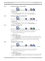
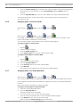
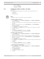
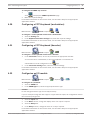
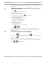
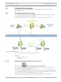
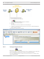
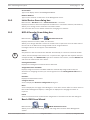
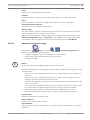
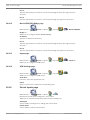
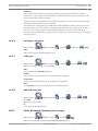
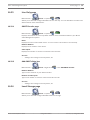
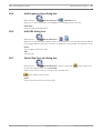
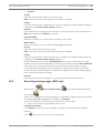
6.1
Configuring devices | en
23
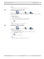
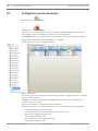
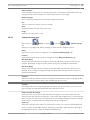
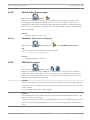
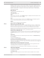
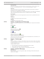
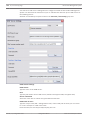
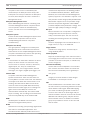
Adding multiple Management Server computers
Main window >
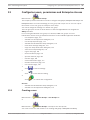
Devices > Enterprise System > Server List
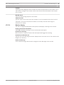
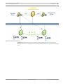
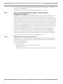
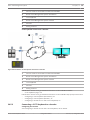
You perform this task of adding multiple Management Server computers in Configuration
Client on the Enterprise Management Server.
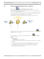
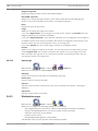
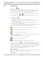
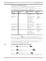
You add multiple Management Server computers to configure a Bosch VMS Enterprise System. A
user of Operator Client can log on with user name of a member an Enterprise User Group to
get simultaneous access to these Management Server computers.
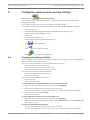
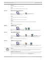
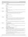
The following illustration shows the part of the scenario where you perform this task:
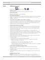
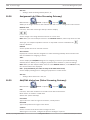
Operating permissions are configured on the Enterprise Management Server in
User
Groups, Enterprise User Group tab.
Device permissions are configured on each Management Server in
User Groups,
Enterprise Access tab.
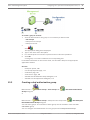
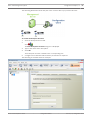
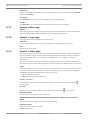
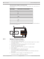
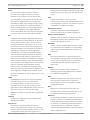
To add:
1.
Click Add Server.
The Add Server dialog box is displayed.
2.
Type in a display name for the server and the network address (DNS name or IP address).
3.
Click OK.
4.
P
Repeat these steps until you have added all desired Management Server computers.
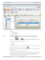
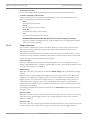
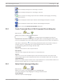
The Management Server computers for your Enterprise System are configured.
Now configure the desired Enterprise User Groups and the Enterprise Access.
The following screenshot shows an example:
Bosch Sicherheitssysteme GmbH
Configuration Manual
2012.07 | V1 | Configuration Client
24
en | Configuring devices
Bosch Video Management System
See also
6.2
–
Server List page, 96
–
Enterprise System, 188
–
User Groups page, 172
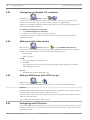
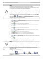
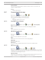
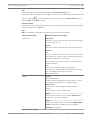
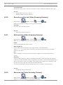
Detecting NVRs, their recorded encoders, and decoders
Main window >
Devices >
NVR & Decoder Scan > NVR & Decoder Scan dialog
box
You scan the network to detect the following devices:
–
NVRs
–
Decoders
–
Encoders
The system automatically adds a default analog monitor group with the detected decoders
assigned. This analog monitor group is added below
.
When you scan the network for the first time, NVRs and decoders are automatically assigned
to the system.
You must manually assign detected encoders to NVRs.
To avoid conflicts with duplicate IP addresses you start the initial device scan. This is useful
when you integrate new devices in your network which have duplicate IP addresses or the
factory default IP address (192.168.0.1). You cannot perform this initial device scan
successfully with devices that are password protected.
2012.07 | V1 | Configuration Client
Configuration Manual
Bosch Sicherheitssysteme GmbH
Bosch Video Management System
Configuring devices | en
25
When you want to add devices that are not members of the same subnet, perform the initial
device scan.
To start the initial device scan:
1.
On the Hardware menu, click Initial Device Scan....
The Initial Device Scan dialog box is displayed.
2.
Click a cell to change the desired address. For changing multiple devices, select the
desired rows. You can select multiple devices by pressing the CTRL- or the SHIFT-key.
Then right-click the selected rows and click Set IP Addresses... or click Set Subnet
Mask... to change the corresponding values.
You must enter the correct subnet mask before changing an IP address.
3.
Click OK.
To scan the network:
1.
Click
.
The NVR & Decoder Scan dialog box is displayed and all available NVRs, decoders, and
encoders are detected.
The detected decoders are listed in the Decoders list and assigned automatically to the
tree item of the Device Tree. If no analog monitor group has already been created,
the detected decoders are added to a new analog monitor group under
>
.
If you do not want to use a decoder or an NVR, remove the item manually: right-click the
item and click Remove.
The detected NVRs are assigned automatically to the
2.
tree item of the Device Tree.
In the Unassigned Encoders list, select an encoder and drag it to an NVR in the Assigned
Encoders and NVRs list. The encoder’s cameras are recorded on the selected NVR.
3.
Repeat the above step for every detected encoder that you want to be part of your
system. Encoders that you do not drag to an NVR, are completely invisible in Bosch Video
Management System.
4.
Click Next >.
If required, a dialog box is displayed for changing the device names of the connected
devices of the detected IP devices to be used for display. Bosch Video Management
System names the devices with default names. If desired, you can use the existing names
of the devices.
5.
Make the required settings. For changing the displayed device names of a complete
column at once, right-click a column with check boxes and click Select Column.
6.
Click Finish.
6.3
Detecting VRM devices
6.4
Configuring NVRs
Main window >
Devices
This chapter provides information on how to configure NVRs in your system.
Primary NVRs record the images of all assigned encoders and IP cameras connected to your
system.
Bosch Sicherheitssysteme GmbH
Configuration Manual
2012.07 | V1 | Configuration Client
26
en | Configuring devices
Bosch Video Management System
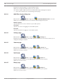
A Failover NVR is a server that takes over the tasks of a failing Primary NVR. The Failover NVR
starts recording as soon as the Primary NVR fails. A Failover NVR cannot have any encoders
directly assigned. A Failover NVR can take over the tasks of a Primary NVR even when
Management Server is not available.
You can assign maximum one Failover NVR to a Primary NVR and you can assign multiple
Primary NVRs to one Failover NVR.
When the Primary NVR works correctly again, the Primary NVR takes back his tasks from the
Failover NVR automatically. The Failover NVR stops recording some seconds after the Primary
NVR has started recording. The recordings of the down time stay on the Failover NVR.
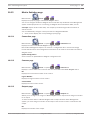
A Redundant NVR performs the same recording tasks as the assigned Primary NVR. A Primary
NVR can have maximum one Redundant NVR assigned. On a Redundant NVR, you cannot
configure the recording and event settings of the assigned devices independently from the
Primary NVR. A Redundant NVR just retrieves video and audio streams and forwards them to a
database. When you change the recording settings on the Primary NVR, these settings are
synchronized on the Redundant NVR.
If you remove an NVR from the Device Tree, the recordings of this NVR are not deleted. You
can retrieve them by activating a previous configuration version containing this NVR.
You can assign a Failover NVR to a Redundant NVR. When the Redundant NVR fails, the
Failover NVR takes over its tasks, i.e. it acts like a Redundant NVR.
The recordings are performed in different modes depending on your configuration:
–
Continuous recording
–
Pre-event recording
–
Motion recording
–
Alarm recording
1.
Click
to save the settings.
Click
to undo the last setting.
2.
3.
Click
6.4.1
to activate the configuration.
Configuring a Primary NVR
Main window >
Devices > Expand
> Expand
>
You can perform the following tasks to configure a selected NVR:
–
Configure video and audio storage
–
Assign a Failover NVR
–
Configure backup
To configure an NVR:
1.
Click the Global Settings tab to assign a Failover NVR to this NVR. The Switch over to:
list contains only NVRs that have been configured as Failover NVRs.
2.
3.
Click the Disk Storage tab to configure the storage settings of the selected NVR.
Click the Camera Storage tab to define minimum and maximum storage times, manage
protected recordings, and to optionally schedule the backup of the assigned cameras. If
scheduled backups are desired, you must first create a Task Schedule in Schedules.
Related Topics
2012.07 | V1 | Configuration Client
Configuration Manual
Bosch Sicherheitssysteme GmbH
Bosch Video Management System
6.4.2
Configuring devices | en
27
Switching an NVR to a Failover NVR
Main window >
Devices > Expand
> Expand
>
To configure a Failover NVR you must first change an NVR to a Failover NVR.
To switch an NVR:
6.4.3
1.
Right-click an NVR. This NVR must not have any encoders assigned.
2.
Click Act as Failover NVR. The NVR is moved to the Failover NVRs node.
Switching an NVR to a Redundant NVR
Main window >
Devices > Expand
> Expand
>
To configure a Redundant NVR you must first change an NVR to a Redundant NVR.
To switch an NVR:
6.4.4
1.
Right-click an NVR. This NVR must not have any encoders assigned.
2.
Click Act as Redundant. The NVR is moved to the Redundant NVRs node.
Configuring a Failover NVR
Main window >
Devices > Expand
> Expand
>
Before you can configure a Failover NVR you must switch a Primary NVR to a Failover NVR.
After having configured a Failover NVR, you assign it to one or multiple NVRs.
You can perform the following tasks to configure a selected Failover NVR:
–
Configuring video and audio storage
–
Assigning NVRs
To configure a Failover NVR:
1.
Click the Global Settings tab to display network settings of the selected Failover NVR.
2.
Click the Disk Storage tab to configure the storage settings of the selected Failover NVR.
3.
Click the Assigned NVRs tab to add or remove NVRs to the selected Failover NVR.
For detailed information on the various fields, see the Online Help for the appropriate
application window.
6.4.5
Configuring a Redundant NVR
Main window >
Devices > Expand
> Expand
>
Before you can configure a Redundant NVR you must switch a Primary NVR to a Redundant
NVR.
After having configured a Redundant NVR, you assign it to one or multiple NVRs.
You can perform the following tasks to configure a selected Redundant NVR:
–
Configuring video and audio storage
–
Assigning NVRs
To configure a Redundant NVR:
1.
Click the Global Settings tab to display network settings of the selected Redundant NVR.
2.
Click the Disk Storage tab to configure the storage settings of the selected Redundant
NVR.
Bosch Sicherheitssysteme GmbH
Configuration Manual
2012.07 | V1 | Configuration Client
28
en | Configuring devices
3.
Bosch Video Management System
Click the Camera Storage tab to configure the camera settings of the selected Redundant
NVR. This page is only available, if on the Assigned NVR page the Backup option is
checked.
4.
Click the Assigned NVR tab to add or remove NVRs to the selected Redundant NVR
For detailed information on the various fields, see the Online Help for the appropriate
application window.
6.4.6
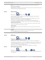
Assigning NVRs to Failover NVRs
Main window >
Devices > Expand
> Expand
Devices > Expand
> Expand
or
Main window >
For an NVR, you can configure a Failover NVR that takes over the tasks of the NVR if it fails.
Ensure that an NVR is switched to a Failover NVR.
You can easily configure several NVRs to have a Failover NVR assigned.
To assign an NVR to a Failover NVR:
1.
Expand
.
2.
Select an NVR as required.
3.
Click the Global Settings tab.
4.
In the Failover NVR list, select the required Failover NVR.
To assign multiple NVRs to a Failover NVR:
1.
Expand
.
2.
Select the desired Failover NVR.
3.
Click the Assigned NVRs tab.
4.
In the Time [h] column, select the required NVRs.
5.
Click Add NVR.
Each added Primary NVR has the selected Failover NVR assigned.
6.4.7
Assigning NVRs to a Redundant NVR
Main window >
Devices > Expand
> Expand
You can only assign one NVR to a Redundant NVR. If you select a Primary NVR that already has
been assigned to another Redundant NVR, the assignment to the previous Redundant NVR is
removed.
Ensure that an NVR is switched to a Redundant NVR.
To assign a Primary NVR to a Redundant NVR:
1.
Select the desired Redundant NVR.
2.
Click the Assigned NVR tab.
The table displays all Primary NVRs.
3.
In the first column, click to check the desired NVR.
Each checked primary NVR has the selected Redundant NVR assigned.
4.
In the Backup column, make the desired setting.
When cleared, the Camera Storage tab becomes active.
2012.07 | V1 | Configuration Client
Configuration Manual
Bosch Sicherheitssysteme GmbH
Bosch Video Management System
6.4.8
Configuring devices | en
29
Displaying information on an NVR
Main window >
Devices> Expand
> Expand
>
You can display the following information on an NVR:
–
Network related information
–
Disk usage statistics and the available disk space on the NVR.
To display information on an NVR:
4 Click the Disk Storage tab to view information on the selected NVR.
6.4.9
Changing the network address of an NVR / Failover NVR / Redundant NVR
Main window >
Devices> Expand
> Expand
or
Main window >
Devices > Expand
> Expand
Devices > Expand
> Expand
or
Main window >
To change the IP address of an NVR / Failover NVR / Redundant NVR:
1.
Right-click
/
/
and click Change network address.
The Network address dialog box is displayed.
2.
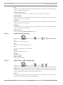
6.5
Change the entry in the field according to your requirements.
Adding a device
Main window >
Devices
You add the following devices to the Device Tree manually because these devices are not
added by a network scan:
–
ONVIF cameras
–
Video Streaming Gateway devices
–
DiBos system
–
Analog matrix
For adding a Bosch Allegiant device, you need a valid Allegiant configuration file.
–
Bosch Video Management System workstation
A workstation must have the Operator Client software installed.
–
Communication device
–
Bosch ATM/POS Bridge, ATM device
–
Virtual input
–
Network monitoring device
–
CCTV keyboard
–
Analog monitor group
Bosch Sicherheitssysteme GmbH
Configuration Manual
2012.07 | V1 | Configuration Client
30
en | Configuring devices
Bosch Video Management System
–
I/O module
–
Allegiant CCL emulation
Decoders, encoders, NVRs including VIDOS NVRs, and VRMs are detected by the network
scan.
i
Notice!
After having added a device, click
to save the settings.
To add a DiBos system:
1.
Right-click
2.
.
Click Add DiBos/BRS Recorder.
The Add DiBos/BRS System dialog box is displayed.
3.
Enter the appropriate values.
4.
Click Scan.
The DiBos system is added to your system.
5.
In the displayed message box, click OK to confirm.
To add a Bosch Allegiant device:
1.
Right-click
and click Add Allegiant.
The Open dialog box is displayed.
2.
Select the appropriate Allegiant configuration file and click OK.
The Bosch Allegiant device is added to your system.
Note: You can add only one Bosch Allegiant matrix.
To add a Bosch Video Management System workstation:
1.
and click Add Workstation.
Right-click
The Add Workstation dialog box is displayed.
2.
Enter the appropriate value click OK.
The workstation
is added to your system.
To add an analog monitor group:
1.
Expand
, right-click
and click Add Monitor Group.
The Create New Analog Monitor Group dialog box is displayed.
If you already have performed a network scan, and decoders have been detected, there is
already a default analog monitor group available with all detected decoders assigned.
2.
Make the appropriate settings.
3.
Click OK.
The analog monitor group is added to your system.
To add a communication device:
1.
Expand
, right-click
and click the required command.
The appropriate dialog box is displayed.
2.
Enter the appropriate settings.
3.
Click OK.
The communication device is added to your system.
2012.07 | V1 | Configuration Client
Configuration Manual
Bosch Sicherheitssysteme GmbH
Bosch Video Management System
Configuring devices | en
31
To add a peripheral device:
1.
Expand
, right-click
and click the required command.
The appropriate dialog box is displayed.
2.
Enter the appropriate settings.
3.
Click OK.
The peripheral device is added to your system.
To add a virtual input:
1.
Expand
, click
.
The corresponding page is displayed.
2.
Click Add Inputs.
A row is added to the table.
3.
Make the appropriate settings.
4.
Click Add .
The virtual input is added to your system.
To add a network monitoring device:
1.
Expand
, right-click
and click Add SNMP.
The Add SNMP dialog box is displayed.
2.
Type a name for the SNMP device.
The network monitoring device is added to your system.
To add a CCTV keyboard:
1.
Expand
, click
.
The corresponding page is displayed.
2.
Click Add Keyboard.
A row is added to the table.
3.
Make the appropriate settings.
The keyboard is added to your system.
To add an I/O module:
1.
Expand
, right-click
and click Add New ADAM Device.
The Add ADAM dialog box is displayed.
2.
Type the IP address of the device.
If you want to skip the currently selected device and jump to the next one, click Skip.
3.
Select the device type.
The corresponding page is displayed.
4.
Click the Inputs tab to change the display names of the inputs if required.
5.
Click the Name tab to change the display names of the Relays if required.
Notice!
i
You can also perform a scan for ADAM devices (Scan for ADAM Devices). The IP addresses of
the devices are detected. If available the device type is preselected. You must confirm this selection.
Bosch Sicherheitssysteme GmbH
Configuration Manual
2012.07 | V1 | Configuration Client
32
en | Configuring devices
Bosch Video Management System
To add an Allegiant CCL emulation:
1.
Expand
, click
.
The Allegiant CCL Emulation tab is displayed.
2.
Click to check Enable Allegiant CCL Emulation.
3.
Make the required settings.
The Allegiant CCL emulation service is started on the Management Server.
Configuring an encoder / decoder
6.6
To configure an encoder:
Main window >
Devices > Expand
> Expand
> Expand
Devices > Expand
> Expand
>
> Expand
>
>
or
Main window >
or
Main window >
Devices >
>
To configure a decoder:
Main window >
Devices > Expand
To configure an encoder or a decoder:
4 Make the appropriate settings on the tab pages of the encoder or decoder.
See the Online Help for the
i
6.7
pages for details.
Notice!
IP devices can be connected that do not have all configuration pages that are described here.
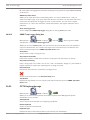
Configuring a decoder for use with a CCTV keyboard
Main window >
Devices > Expand
> Expand
Perform the following steps to configure a VIP XD decoder that is connected to a CCTV
keyboard.
To configure a decoder:
1.
Click the appropriate decoder which is used for connecting a CCTV keyboard.
2.
Click the Periphery tab.
3.
Ensure that the following settings are applied:
–
Serial port function: Transparent
–
Baud rate: 19200
–
Stop bits: 1
2012.07 | V1 | Configuration Client
Configuration Manual
Bosch Sicherheitssysteme GmbH
Bosch Video Management System
Configuring devices | en
–
Parity check: None
–
Interface mode: RS232
–
Half-duplex mode: Off
33
Configuring multiple encoders / decoders
6.8
Main window
You can modify the following properties of multiple encoders and decoders at once:
i
–
Display names
–
IP addresses
–
Firmware versions
Notice!
Changing the IP address of an IP device can make it unreachable.
To configure multiple IP addresses:
1.
On the Hardware menu, click IP Device Configuration.... The IP Device Configuration
2.
Select the required devices. You can select multiple devices by pressing the CTRL- or the
dialog box is displayed.
SHIFT-key.
3.
Right-click the selected devices and click Set IP Addresses.... The Set IP Addresses
dialog box is displayed.
4.
In the Start with: field, type the first IP address.
5.
Click Calculate. In the End with: field, the last IP address of the range for the selected
devices is displayed.
6.
Click OK.
7.
In the IP Device Configuration... dialog box, click Apply.
The new IP addresses are updated in the selected devices.
To configure multiple display names:
1.
On the Hardware menu, click IP Device Configuration.... The IP Device Configuration
dialog box is displayed.
2.
Select the required devices. Multiple selection is possible by pressing the SHIFT key.
3.
Right-click the selected devices and click Set Display Names... The Set Display Names
dialog box is displayed.
4.
In the Start with: field, type the first string.
5.
Click Calculate. In the End with: field, the last string of the range for the selected devices
is displayed.
6.
Click OK.
7.
In the IP Device Configuration... dialog box, click Apply.
The calculated names are updated in the selected devices.
To update firmware for multiple devices:
1.
On the Hardware menu, click IP Device Configuration.... The IP Device Configuration
dialog box is displayed.
2.
Select the required devices.
3.
Click Update Firmware.
4.
Select the file containing the update.
5.
Click OK.
Bosch Sicherheitssysteme GmbH
Configuration Manual
2012.07 | V1 | Configuration Client
34
en | Configuring devices
Bosch Video Management System
Configuring a DiBos system
6.9
Main window >
i
Devices > Expand
>
Notice!
You do not configure the DiBos system itself but only the Bosch Video Management System
related properties.
To scan for new DiBos devices:
4
Right-click
and click Scan for DiBos Devices.
The DiBos system is scanned for new devices and they are added.
To remove an item:
1.
Click the Cameras tab, the Relays tab, or the Inputs tab.
2.
Right-click an item and click Remove. The item is removed.
To rename a DiBos device:
6.10
1.
Right-click a DiBos device and click Rename.
2.
Type the new name for the item.
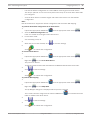
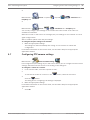
Configuring a Bosch Allegiant device
Main window >
Devices > Expand
>
You do not configure the Bosch Allegiant device itself but only the Bosch Video Management
System related properties.
To assign an output to an encoder:
1.
Click the Outputs tab.
2.
In the Usage column, click Digital Trunk in the desired cells.
3.
In the Encoder column, select the desired encoder.
Adding an input to a Bosch Allegiant device:
1.
Click the Inputs tab.
2.
Click Add Inputs. A new row is added to table.
3.
Type the required settings in the cells.
Deleting an input:
6.11
6.12
1.
Click the Inputs tab.
2.
Click the required table row.
3.
Click Delete Input. The row is deleted from the table.
Configuring a startup Command Script
See Configuring a startup Command Script, 67.
Changing the network address of a workstation
Main window >
Devices > Expand
To change the IP address:
1.
Right-click
and click Change Network Address.
The Change Network Address dialog box is displayed.
2012.07 | V1 | Configuration Client
Configuration Manual
Bosch Sicherheitssysteme GmbH
Bosch Video Management System
2.
6.13
Configuring devices | en
35
Change the entry in the field according to your requirements.
Enabling Forensic Search on a workstation
Main window >
Devices > Expand
>
> Settings page
You must enable Forensic Search on a workstation.
Note:
Enable video content analysis on each encoder. Use the VCA page of the encoder in the Device
Tree.
To enable Forensic Search:
4 Click to select the Enable Forensic Search check box.
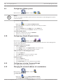
6.14
Assigning an analog monitor group to a workstation
Main window >
Devices > Expand
>
> Analog Monitor Groups page
You assign an analog monitor group to a Bosch Video Management System workstation. In the
Options dialog box, you can configure that all workstations can control analog monitor groups
regardless of the setting here.
To assign an analog monitor group:
4 In the Assigned Analog Monitor Groups column, select the check box.
6.15
Configuring an analog monitor group
Main window >
Devices > Expand
>
Caution!
You cannot control an analog monitor group from within Operator Client when the connection
to the Management Server is lost or when Operator Client with Enterprise System is used.
You configure the monitors in an analog monitor group logically in rows and columns. This
arrangement does not have to meet the physical arrangement of the monitors.
To configure an analog monitor group:
1.
In the Name: field, type a name for the analog monitor group.
2.
In the Columns: and Rows: fields, enter the desired values.
3.
Drag each available decoder to an analog monitor image on the right.
The logical number of the decoder is displayed as a black number on the monitor image
and the color of this image changes.
If no decoder is available, unassign a decoder from another analog monitor group or
repeat network scan.
4.
Click the Advanced Configuration tab.
5.
Change the logical numbers of the assigned decoders as required. If you enter an already
used number, a message box is displayed.
6.
Click Quad View to enable quad view for this decoder.
Note:
We do not recommend configuring quad view for H.264 cameras.
7.
In the Initial Camera column, select the desired camera.
8.
In the OSD related columns, select the desired options.
Bosch Sicherheitssysteme GmbH
Configuration Manual
2012.07 | V1 | Configuration Client
36
en | Configuring devices
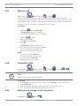
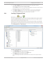
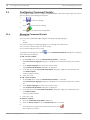
6.16
Bosch Video Management System
Adding a monitor wall
Main window >
Devices > Right-click
Main window >
Maps and Structure
> Click Add Monitor Wall
After having added the monitor wall, the user of Operator Client can control this monitor wall.
The user can change the monitor layout and assign encoders to monitors.
To add:
1.
Select the desired decoder.
2.
If required, enter the maximum number of monitors and configure thumbnails.
3.
Click
.
4.
Click
5.
6.
Maps and Structure.
Drag the monitor wall to the Logical Tree.
If required, configure the access to the monitor wall with corresponding user group
permissions.
See also
–
6.17
Add Monitor Wall dialog box, 110
Configuring a communication device
Main window >
Devices > Expand
> Expand
To configure a communication device:
1.
Click the required device:
2.
or
.
Make the appropriate settings.
For detailed information on the various fields, see the Online Help for the appropriate
application window.
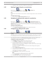
6.18
Configuring a peripheral device
Main window >
Devices > Expand
> Expand
>
or
To configure a peripheral device:
4 Change the required settings.
For detailed information on the various fields, see the Online Help for the appropriate
application window.
6.19
Configuring network monitoring
Main window >
2012.07 | V1 | Configuration Client
Devices> Expand
Configuration Manual
Bosch Sicherheitssysteme GmbH
Bosch Video Management System
Configuring devices | en
37
To configure the SNMP trap receiver:
1.
Click
2.
to display the SNMP Trap Receiver page.
Make the required settings.
For detailed information on the various fields, see the Online Help for the appropriate
application window.
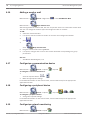
6.20
Configuring a CCTV keyboard (workstation)
Main window >
Devices> Expand
>
To configure a CCTV keyboard connected to a workstation:
1.
Click the Settings tab.
2.
In the Keyboard Serial Port Settings field, make the required settings.
For detailed information on the various fields, see the Online Help for the appropriate
application window.
6.21
Configuring a CCTV keyboard (decoder)
Main window >
Devices> Expand
>
To configure a CCTV keyboard connected to a decoder:
1.
In the Connection column, click a cell, and select the appropriate decoder.
You can also select a workstation, if the CCTV keyboard is connected to it.
A workstation must be configured on the
2.
page.
In the Connection Settings field, make the required settings.
For detailed information on the various fields, see the Online Help for the appropriate
application window.
6.22
Configuring an I/O module
Main window >
Devices> Expand
> Expand
>
To configure an I/O module:
1.
Click the ADAM tab.
2.
In the ADAM type: list, select the appropriate device type.
Caution!
Do not change the device type if not really necessary.
If you for example change the device type to a type with less inputs, all configuration data for
the removed inputs get lost.
1.
Click the Inputs tab.
2.
In the Name column, change the display name of an input if required.
3.
Click the Relays tab.
4.
In the Relays column, change the name of a relay if required.
For detailed information on the various fields, see the Online Help for the appropriate
application window.
Bosch Sicherheitssysteme GmbH
Configuration Manual
2012.07 | V1 | Configuration Client
38
en | Configuring devices
6.23
Bosch Video Management System
Configuring an Allegiant CCL emulation
Main window >
Devices> Expand
>
To use the CCL commands you need the CCL User Guide. This manual is available in the
Online Product Catalog in the document section of each LTC Allegiant Matrix.
Allegiant CCL commands supported in Bosch VMS, 196 lists the CCL commands supported in
Bosch Video Management System.
To configure an Allegiant CCL emulation:
1.
Click Enable Allegiant CCL Emulation.
2.
Configure the communication settings as required.
For detailed information on the various fields, see the Online Help for the appropriate
application window.
6.24
Adding a mobile video service
Main window >
Devices >Right-click
> Click Add Mobile Video Service
You can add a transcoding service to your Bosch Video Management System. The following
devices can receive video data from Bosch Video Management System:
–
iPad (via App)
–
iPhone (via App)
To add:
1.
Type in the URI of your mobile device.
2.
P
Click OK.
The configured device can now receive live and playback video data from your Bosch
Video Management System.
See also
–
6.25
Add Mobile Video Service dialog box, 119
Adding a VRM device with iSCSI storage
Main window >
Devices >
In your network, you need a VRM service running on a computer, and an iSCSI device.
Caution!
When you add an iSCSI device with no targets and LUNs configured, start a default configuration and add the IQN of each encoder to this iSCSI device.
When you add an iSCSI device with targets and LUNs pre-configured, add the IQN of each encoder to this iSCSI device.
See Configuring an iSCSI device, 38 for details.
6.26
Configuring an iSCSI device
After adding VRM devices, iSCSI devices, and encoders, perform the following tasks to ensure
that video data of encoders is stored on the iSCSI devices or video data can be retrieved from
these iSCSI devices:
2012.07 | V1 | Configuration Client
Configuration Manual
Bosch Sicherheitssysteme GmbH
Configuring devices | en
Bosch Video Management System
–
39
Execute the default configuration to create LUNs on each target of the iSCSI device.
This step is optional. You do not need to perform this step on an iSCSI device with LUNs
pre-configured.
–
Scan the iSCSI device to add the targets and LUNs to the Device Tree after default
configuration.
Note:
Not all iSCSI devices support the default configuration and automatic IQN mapping.
To perform the default configuration of an iSCSI device:
1.
Expand the appropriate VRM device
2.
, click the appropriate iSCSI device
.
Click the Default Configuration tab.
LUNs are created on the targets of the iSCSI device.
3.
Format these LUNs.
See Formatting a LUN, 40.
4.
When the process has finished, click
to save the settings.
5.
Click
to activate the configuration.
To scan the iSCSI device:
1.
Expand the appropriate VRM device
, click the appropriate iSCSI device
.
2.
Right-click
and click Scan ISCSI Device.
The process is started.
Targets and LUNs are detected and added to the Device Tree below the iSCSI node.
3.
Click
to save the settings.
4.
Click
to activate the configuration.
To perform IQN mapping:
1.
Expand the appropriate VRM device
, click the appropriate iSCSI device
.
2.
Right-click
and click Map IQNs.
The iqn-Mapper dialog box is displayed and the process is started.
The encoders that are assigned to the selected VRM device
are evaluated and their
IQNs are added to this iSCSI device.
3.
Click
to save the settings.
4.
Click
Bosch Sicherheitssysteme GmbH
to activate the configuration.
Configuration Manual
2012.07 | V1 | Configuration Client
40
en | Configuring devices
Bosch Video Management System
Adding a LUN
6.27
Main window >
Devices > Expand
> Expand
Usually the network scan adds the desired iSCSI devices with their targets and LUNs
automatically. If your network scan did not work correctly or you want to configure your iSCSI
device offline before it is actually integrated into your network, you configure a target in your
iSCSI device and on this target you configure one or more LUNs.
To configure:
1.
Right-click
and click Add Target.
The Add Target dialog box is displayed.
2.
Enter the desired target number and click Ok.
The target
3.
is added.
Click the new target.
The LUNs page is displayed.
4.
Click Add.
The Add LUN dialog box is displayed.
5.
Enter the desired LUN number and click Ok.
The LUN is added as a new table row.
Repeat this step for each desired LUN.
Notes:
–
To remove a LUN, click Remove.
The video data remains on this LUN.
–
To format a LUN, click Format.
All data on this LUN is removed!
6.28
Formatting a LUN
Main window >
Devices > Expand
> Expand
> Expand
>
You format a LUN to prepare it for the first use.
i
Notice!
All data on the LUN is lost after formatting.
To configure:
1.
On the LUNs page, select the desired LUN and, in the Format column, click to check.
2.
Click Format LUN.
3.
Read the displayed message carefully and confirm the message if desired.
The selected LUN is formatted. All data on this LUN is lost.
6.29
Adding a local storage or live only device
Main window >
2012.07 | V1 | Configuration Client
Devices >
Configuration Manual
Bosch Sicherheitssysteme GmbH
Bosch Video Management System
Configuring devices | en
41
or
Main window >
Devices >
You can add Bosch or ONVIF encoders with local storage or live only encoders.
To add a local storage:
1.
Right-click
and click Scan Local Storage Encoders.
The Bosch VMS Scan Wizard is displayed.
2.
Assign the device.
If required assign multiple devices.
3.
Click Next >>.
4.
Click Finish.
The next step of the wizard is displayed.
The device is connected to your Bosch Video Management System.
To add a Bosch live only device:
1.
Right-click
and click Scan live-only Encoders.
The Bosch VMS Scan Wizard is displayed.
2.
Assign the device.
If required assign multiple devices.
3.
Click Next >>.
The next step of the wizard is displayed.
4.
Click Finish.
The device is connected to your Bosch Video Management System.
To add an ONVIF live only device:
1.
Right-click
and click Scan live-only ONVIF Encoders.
The Bosch VMS Scan Wizard is displayed.
2.
Assign the device.
If required assign multiple devices.
3.
Click Next >>.
4.
Click Finish.
The next step of the wizard is displayed.
The device is connected to your Bosch Video Management System.
6.30
Adding a Video Streaming Gateway device
Main window >
Devices Expand
> Right-click
> Click Add Streaming
Gateway > Edit Streaming Gateway dialog box
You add a VSG to the system to enable assigning and configuring cameras to this VSG.
To add a VSG:
1.
Make the required settings for your VSG device.
2.
P
The VSG device is added to the system. The cameras assigned to this VSG are recorded.
Click Add.
Bosch Sicherheitssysteme GmbH
Configuration Manual
2012.07 | V1 | Configuration Client
42
en | Configuring devices
Bosch Video Management System
See also
–
6.31
Video Streaming Gateway device page, 123
Adding a Bosch camera to a VSG
Main window >
Devices > Expand
> Expand
>
To add a camera:
1.
Select the desired cameras and click
to add them to the VSG cameras list.
The Add/Edit dialog box is displayed.
Note: Select cameras of the same type, for example only Bosch cameras. Otherwise the
button is disabled.
2.
Type in user name and password and click Connect.
If the connection to the encoder is established successfully, the configuration settings in
the Protocol settings group are active.
If you do not want to wait until the connection is established, click Skip.
3.
In the Type list, select Bosch RCP+.
4.
In the Video input and Stream and Protocol lists make the required settings.
5.
If required, type a name for the camera in the VSG Camera Name column.
6.
Click OK.
7.
Click
.
See also
6.32
–
Add/Edit dialog box (Video Streaming Gateway), 124
–
Assignment tab (Video Streaming Gateway), 124
Adding an ONVIF camera to a VSG
Main window >
Devices > Expand
> Expand
>
To add a camera:
1.
Select the desired cameras and click
to add them to the VSG cameras list.
The Add/Edit dialog box is displayed.
Note: Select cameras of the same type, for example only Bosch cameras. Otherwise the
button is disabled.
2.
Type in user name and password and click Connect.
If the connection to the encoder is established successfully, the configuration settings in
the Protocol settings group are active.
If you do not want to wait until the connection is established, click Skip.
3.
In the Type list, select ONVIF.
4.
In the Stream and Token lists make the required settings.
5.
If required, type a name for the camera in the VSG Camera Name column.
6.
Click OK.
7.
Click
2012.07 | V1 | Configuration Client
.
Configuration Manual
Bosch Sicherheitssysteme GmbH
Bosch Video Management System
Configuring devices | en
43
See also
–
6.33
Add/Edit dialog box (Video Streaming Gateway), 124
Configuring multicast for VSG
Main window >
Devices > Expand
> Expand
>
For each camera assigned to a Video Streaming Gateway device you can configure a multicast
address with port.
To configure multicast:
1.
Click to enable multicast.
2.
Type in a valid multicast address and a port number.
3.
If required, configure continuous multicast streaming.
4.
Click
.
See also
–
6.34
Multicast tabs (Video Streaming Gateway), 126
Switching on VSG recording
Main window >
Devices > Expand
> Expand
>
To switch on:
1.
Click the Recording Profiles tab.
2.
Select the line of the camera, for which you want to switch on recording.
3.
In the Recording list, select On.
4.
Click
.
Recording for this camera starts.
See also
–
Recording profiles tab (Video Streaming Gateway), 126
Bosch Sicherheitssysteme GmbH
Configuration Manual
2012.07 | V1 | Configuration Client
44
en | Configuring the structure
Bosch Video Management System
Configuring the structure
7
This chapter provides information on how to configure the Logical Tree and how to manage
resource files such as maps.
i
Notice!
If you move a group of devices in the Logical Tree, these devices loose their permission settings. You must set the permissions in the User Groups page again.
Follow these references to get detailed information on the available application windows:
–
Resource Manager dialog box, 151
–
Select Resource dialog box, 151
–
Sequence Builder dialog box, 151
–
Add Sequence dialog box, 152
–
Add Sequence Step dialog box, 153
–
Add URL dialog box, 153
–
Select Map for Link dialog box, 153
1.
Click
to save the settings.
Click
to undo the last setting.
2.
3.
Click
to activate the configuration.
7.1
Configuring the Logical Tree
7.2
Adding a device to the Logical Tree
Main window >
Maps and Structure
To add a device:
4 Drag an item from the Device Tree to the required location in the Logical Tree.
You can drag a complete node with all sub-items from the Device Tree to the Logical Tree.
You can select multiple devices by pressing the CTRL- or the SHIFT-key.
7.3
Removing a tree item
Main window >
Maps and Structure
To remove a tree item from the Logical Tree:
4 Right-click an item in the Logical Tree and click Remove. If the selected item has subitems, a message box is displayed. Click OK to confirm. The item is removed.
When you remove an item from a map folder of the Logical Tree, it is also removed from
the map.
7.4
Managing resource files
Main window >
Maps and Structure >
or
2012.07 | V1 | Configuration Client
Configuration Manual
Bosch Sicherheitssysteme GmbH
Bosch Video Management System
Configuring the structure | en
Main window >
45
Alarms >
You can import resource files in the following formats:
–
DWF files (2 D, map resource files)
For use in Operator Client, these files are converted to a bitmap format.
–
HTML files (map document files)
–
MP3 (audio file)
–
TXT files (Command Scripts or camera sequences)
–
MHT files (Web archives)
–
URL files (links to Web pages)
–
WAV (audio file)
The imported resource files are added to a database. They are not linked to the original files.
Notice!
i
After each of the following tasks:
Click
to save the settings.
To import a resource file:
1.
Click
.
The Import Resource dialog box is displayed.
2.
Select one or more files.
3.
Click Open.
The selected files are added to the list.
If a file has already been imported, a message box is displayed.
If you decide to import an already imported file again, a new entry is added to the list.
To remove a resource file:
1.
Select a resource file.
2.
Click
.
The selected resource file is removed from the list.
To rename a resource file:
1.
Select a resource file.
2.
Click
3.
.
Enter the new name.
The original file name and creation date persists.
To replace the content of a resource file:
1.
Select a resource file.
2.
Click
.
The Replace Resource dialog box is displayed.
3.
Select a file with the appropriate content and click Open.
The resource name persists, the original file name is exchanged with the new file name.
To export a resource file:
1.
Select a resource file.
Bosch Sicherheitssysteme GmbH
Configuration Manual
2012.07 | V1 | Configuration Client
46
en | Configuring the structure
Bosch Video Management System
2.
Click
.
A dialog box for selecting a directory is displayed.
3.
Select the appropriate directory and click OK.
The original file is exported.
7.5
Adding a Command Script
Main window >
Maps and Structure
Before you can add a Command Script, you must have Command Script files imported or
created.
If required, see Configuring Command Scripts, 66 for details.
To add a Command Script file:
1.
Select a folder where you want to add the new Command Script.
2.
Click
. The Select Client Script dialog box is displayed.
3.
Select a file in the list.
4.
Click OK.
A new Command Script is added under the selected folder.
Managing pre-configured camera sequences
7.6
Main window >
Maps and Structure
You can perform the following tasks for managing camera sequences:
–
Create a camera sequence
–
Add a step with a new dwell time to an existing camera sequence
–
Remove a step from camera sequence
–
Delete a camera sequence
Notice!
When the configuration is changed and activated, a camera sequence (pre-configured or automatic) usually is continued after restart of the Operator Client.
i
But in the following cases the sequence is not continued:
A monitor where the sequence is configured to be displayed has been removed.
The mode of a monitor (single/quad view) where the sequence is configured to be displayed
has been changed.
The logical number of a monitor where the sequence is configured to be displayed is
changed.
Notice!
i
After each of the following tasks:
Click
to save the settings.
To create a camera sequence:
1.
In the Logical Tree, select a folder where you want to create the camera sequence.
2012.07 | V1 | Configuration Client
Configuration Manual
Bosch Sicherheitssysteme GmbH
Bosch Video Management System
Configuring the structure | en
47
2.
Click
.
The Sequence Builder dialog box is displayed.
3.
In the Sequence Builder dialog box, click
.
The Add Sequence dialog box is displayed.
4.
Enter the appropriate values.
For detailed information on the various fields, see the Online Help for the appropriate
application window.
4 Click OK.
A new camera sequence
is added.
To add a step with a new dwell time to a camera sequence:
1.
Select the desired camera sequence.
2.
Click Add Step.
The Add Sequence Step dialog box is displayed.
3.
Make the appropriate settings.
4.
Click OK.
A new step is added to the camera sequence.
To remove a step from a camera sequence:
4 Right-click the desired camera sequence and click Remove Step.
The step with the highest number is removed.
To delete a camera sequence:
1.
Select the desired camera sequence.
2.
Click
7.7
. The selected camera sequence is removed.
Adding a camera sequence
Main window >
Maps and Structure
You add a camera sequence to the root directory or to a folder of the Logical Tree.
To add a camera sequence:
1.
In the Logical Tree, select a folder where you want to add the new camera sequence.
2.
Click
3.
. The Sequence Builder dialog box is displayed.
In the list, select a camera sequence.
4.
Click Add to Logical Tree. A new
7.8
is added under the selected folder.
Adding a folder
Main window >
Maps and Structure
To add a folder:
1.
Select a folder where you want to add the new folder.
2.
Click
Bosch Sicherheitssysteme GmbH
. A new folder is added under the selected folder.
Configuration Manual
2012.07 | V1 | Configuration Client
48
en | Configuring the structure
Bosch Video Management System
3.
Click
4.
7.9
to rename the folder.
Type the new name and press ENTER.
Adding a map
Main window >
Maps and Structure
Before you can add a map, you must have map resource files imported.
To import a map resource file see Managing resource files, 44 for details.
To add a map:
1.
Ensure that the map resource file that you want to add has already been imported.
2.
Select a folder where you want to add the new map.
3.
Click
4.
. The Select Resource dialog box is displayed.
Select a file in the list.
If the required files are not available in the list, click Manage... to display the Resource
Manager dialog box for importing files.
5.
Click OK.
A new map
is added under the selected folder.
The map is displayed.
All devices within this folder are displayed in the upper left corner of the map.
7.10
Adding a link to another map
Main window >
Maps and Structure
After you have added at least two maps, you can add a link on one map to the other so that
the user can click from one map to a linked one.
To add a link:
1.
Click a map folder
2.
in the Logical Tree.
Right-click the map and click Create Link.
The Select Map for Link dialog box is displayed.
3.
In the dialog box, click a map
7.11
.
4.
Click Select.
5.
Drag the item to the appropriate place on the map.
Assigning a map to a folder
Main window >
Maps and Structure
Before you can assign maps, you must have map resource files imported.
If required, see Managing resource files, 44 for details.
To assign a map resource file:
1.
Right-click a folder and click Assign Map.
The Select Resource dialog box is displayed.
2012.07 | V1 | Configuration Client
Configuration Manual
Bosch Sicherheitssysteme GmbH
Bosch Video Management System
2.
Configuring the structure | en
49
Select a map resource file in the list.
3.
Click OK. The selected folder is displayed as
.
The map is displayed in the map window.
All items within this folder are displayed in the upper left corner of the map.
7.12
Managing devices on a map
Main window >
Maps and Structure
Before you can manage devices on a map you must add a map or assign a map to a folder and
add devices to this folder.
Notice!
i
After each of the following tasks:
Click
to save the settings.
To place items on a map:
1.
Select a map folder.
2.
Drag devices from the Device Tree to the map folder.
The devices of a map folder are located on the left upper corner of the map.
3.
Drag the items to the appropriate places on the map.
To remove an item in the Logical Tree only from the map:
1.
Right-click the item on the map and click Invisible.
The item is removed from the map.
The item remains in the Logical Tree.
2.
To make it visible again, right-click the device in the Logical Tree and click Visible In Map.
To remove an item from the map and from the Full Logical Tree:
4 Right-click the item in the Logical Tree and click Remove.
The item is removed from the map and from the Logical Tree.
To change the icon for the orientation of a camera:
4 Right-click the item, point to Change Image, and then click the appropriate icon.
The icon changes accordingly.
To change the color of an item:
4 Right-click the item and click to Change Color. Select the appropriate color.
The icon changes accordingly.
7.13
Adding a document
Main window >
Maps and Structure
You can add text files, HTML files (including MHT files) or an URL file (containing an Internet
address) as documents. And you can add a link to another application.
Before you can add a document, you must have document files imported.
To import document files see Managing resource files, 44 for details.
To add a map document file:
1.
Ensure that the document file that you want to add has already been imported.
2.
Select a folder where you want to add the new document.
Bosch Sicherheitssysteme GmbH
Configuration Manual
2012.07 | V1 | Configuration Client
50
en | Configuring the structure
Bosch Video Management System
3.
Click
4.
. The Select Resource dialog box is displayed.
Select a file in the list. If the required files are not available in the list, click Manage... to
display the Resource Manager dialog box for importing files.
5.
Click OK. A new document is added under the selected folder.
2012.07 | V1 | Configuration Client
Configuration Manual
Bosch Sicherheitssysteme GmbH
Bosch Video Management System
8
Configuring schedules | en
51
Configuring schedules
Main window >
Schedules
There are two schedule types available:
–
Recording Schedules
–
Task Schedules
You can configure a maximum of 10 different Recording Schedules in the Recording Schedule
Table. In these segments the cameras can behave differently. For example, they can have
different frame rate and resolution settings (to be configured in the Cameras and Recording
page). In every point in time, exactly one Recording Schedule is valid. There are no gaps and
no overlaps.
You configure Task Schedules for scheduling various events which can occur in your system (to
be configured in the Events page).
See glossary for definitions of Recording Schedules and Task Schedules.
The schedules are used in other pages of the Configuration Client:
–
Cameras and Recording page
Used to configure recording.
–
Events page
Used to determine when events cause logging, alarms, or execution of Command Scripts.
–
User Groups page
Used to determine when the members of a user group can log on.
Follow these references to get detailed information on the available application windows:
–
Recording Schedules page, 154
–
4
Task Schedules page, 154
Click
to save the settings.
Click
to undo the last setting.
4
4
Click
8.1
to activate the configuration.
Configuring a Recording Schedule
Main window >
Schedules
You can add exception days and holidays to any Recording Schedule. These settings override
the normal weekly settings.
The sequence of decreasing priority is: exception days, holidays, weekdays.
The maximum number of Recording Schedules is 10. The first three entries are configured by
default. You can change these settings. Entries with the gray icon
do not have a time
period configured.
Recording Schedules share the same weekdays.
Each Standard Task Schedule has its own weekdays patterns.
To configure a Recording Schedule:
1.
In the Recording Schedules tree, select a schedule.
Bosch Sicherheitssysteme GmbH
Configuration Manual
2012.07 | V1 | Configuration Client
52
en | Configuring schedules
Bosch Video Management System
2.
Click the Weekdays tab.
3.
In the Schedule Table field, drag the pointer to select the time periods for the selected
schedule. The selected cells are displayed in the color of the selected schedule.
Notes:
–
You can mark a time period on a weekday of a Recording Schedule with the color of
another Recording Schedule.
8.2
Adding a Task Schedule
Main window >
Schedules
To add a Task Schedule:
1.
Click Add.
2.
Enter the appropriate name.
3.
Click Standard for a standard Task Schedule or Recurring for a recurring Task Schedule.
A new entry is added.
If you change the setting, a message box is displayed. Click OK if you want to change the
schedule type.
A standard Task Schedule is displayed as
4.
8.3
, a recurring Task Schedule as
.
Make the appropriate settings for the selected schedule.
Configuring a standard Task Schedule
Main window >
Schedules
Each standard Task Schedule has its own weekdays patterns.
To configure a standard Task Schedule:
1.
In the Task Schedules tree, select a standard Task Schedule.
2.
Click the Weekdays tab.
3.
In the Schedule Table field, drag the pointer to select the time periods for the selected
schedule.
8.4
Configuring a recurring Task Schedule
Main window >
Schedules
Each recurring Task Schedule has its own day pattern.
To configure a recurring Task Schedule:
1.
In the Task Schedules tree, select a recurring Task Schedule
2.
.
In the Recurrence Pattern field, click the frequency with which you want the Task
Schedule to recur (Daily, Weekly, Monthly, Yearly) and then make the corresponding
settings.
3.
In the Start date: list, select the appropriate start date.
4.
In the Day Pattern field, drag the pointer to select the appropriate time period.
2012.07 | V1 | Configuration Client
Configuration Manual
Bosch Sicherheitssysteme GmbH
Bosch Video Management System
Configuring schedules | en
53
Removing a Task Schedule
8.5
Main window >
> Select an item in the Task Schedules tree
To remove a Task Schedule:
1.
In the Task Schedules tree, select an item.
2.
Click Delete.
The Task Schedule is deleted. All items that are assigned to this schedule, are not
scheduled.
8.6
Adding holidays and exception days
Main window >
Schedules
Caution!
You can configure empty exception days and holidays. Exception days and holidays replace
the schedule of the corresponding week day.
Example:
!
Old configuration:
Weekday schedule configured to be active from 9:00 to 10:00
Exception day schedule configured to be active from 10:00 to 11:00
Result: activity from 10:00 to 11:00
Same behavior is valid for holidays.
You can add holidays and exception days to a Recording Schedule or to a Task Schedule.
Recording Schedules share the same holidays and exception days.
Each standard Task Schedule has its own holidays or exception days patterns.
To add holidays and exception days to a schedule:
1.
In the Recording Schedules or Task Schedules tree, select a schedule.
2.
Click the Holidays tab.
3.
Click Add.
The Add Holiday(s) dialog box is displayed.
4.
Select one or more holidays and click OK.
The selected holidays are added to the Schedule Table.
5.
Drag the pointer to select the appropriate time period (this is not possible for Recording
Schedules).
The selected cells are cleared and vice versa.
6.
Click the Exception Days tab.
7.
Click Add.
8.
Select one or more special days and click OK.
The Add Exception Day(s) dialog box is displayed.
The selected exception days are added to the Schedule Table.
9.
Drag the pointer to select the appropriate time period (this is not possible for Recording
Schedules).
The selected cells are cleared and vice versa.
The sorting order of the added holidays and exception days is chronological.
Bosch Sicherheitssysteme GmbH
Configuration Manual
2012.07 | V1 | Configuration Client
54
en | Configuring schedules
Bosch Video Management System
Notes:
–
You can mark a time period on a holiday or exception day of a Recording Schedule with
the color of another Recording Schedule.
8.7
Removing holidays and exception days
Schedules
Main window >
You can remove holidays and exception days from a Recording Schedule or a Task Schedule.
To remove holidays and exception days from a Task Schedule:
1.
In the Recording Schedules or Task Schedules tree, select a schedule.
2.
Click the Holidays tab.
3.
Click Delete.
4.
Select one or more holidays and click OK.
The Select the holidays to delete dialog box is displayed.
The selected holidays are removed from the Schedule Table.
5.
6.
Click the Exception Days tab.
Click Delete.
The Select the exception days to delete. dialog box is displayed.
7.
Select one or more exception days and click OK.
The selected exception days are removed from the Schedule Table.
8.8
Renaming a schedule
Main window >
To rename a schedule:
1.
In the Recording Schedules or Task Schedules tree, select an item.
2.
Click
3.
.
Enter the new name and press ENTER. The entry is renamed.
2012.07 | V1 | Configuration Client
Configuration Manual
Bosch Sicherheitssysteme GmbH
Bosch Video Management System
9
Configuring cameras and recording settings | en
55
Configuring cameras and recording settings
Main window >
Cameras and Recording
This chapter provides information on how to configure the cameras in your Bosch Video
Management System.
You configure various camera properties and the recording settings.
Follow these references to get detailed information on the available application windows:
–
Cameras page, 156
–
Scheduled Recording Settings dialog box (only VRM and Local Storage), 158
–
Stream Quality Settings dialog box, 160
–
COM1, 143
–
PTZ Settings dialog box, 162
–
4
Copy Recording Settings dialog box (NVR only)
Click
to save the settings.
Click
to undo the last setting.
4
4
Click
9.1
to activate the configuration.
Copying and pasting in tables
You can configure many objects simultaneously within a Camera Table, an Event Configuration
Table, or an Alarm Configuration Table.
You can copy the configurable values of a table row in other rows:
–
Copy all values of a row to other rows.
–
Copy only one value of a row to another row.
–
Copy the value of one cell to a complete column.
You can copy the values in two different ways:
–
Copy into the clipboard and then paste.
–
Direct copy and paste.
You can determine in which rows to paste:
–
Copy in all rows.
–
Copy in selected rows.
To copy and paste all configurable values of a row into another row:
1.
Right-click the row with the desired values and click Copy Row.
2.
Click the row heading of the row that you want to modify.
To select more than one row press the CTRL key and point to the other row headings.
3.
Right-click the table and click Paste.
The values are copied.
To copy and paste one value of a row into another row:
1.
Right-click the row with the desired values and click Copy Row.
2.
Right-click the cell that you want to modify, point to Paste Cell to, and click Current Cell.
The value is copied.
To copy all configurable values directly:
1.
Click the row heading of the row that you want to modify.
To select more than one row press the CTRL key and point to the other row headings.
Bosch Sicherheitssysteme GmbH
Configuration Manual
2012.07 | V1 | Configuration Client
56
en | Configuring cameras and recording settings
2.
Bosch Video Management System
Right-click the row with the desired values, point to Copy Row to, and click Selected
Rows.
The values are copied.
To copy one value directly:
1.
Click the row heading of the row that you want to modify.
To select more than one row press the CTRL key and point to the other row headings.
2.
Right-click the cell with the desired value, point to Copy Cell to, and click Selection in
Column .
The value is copied.
To copy a value of a cell to all other cells in this column:
4 Right-click the cell with the desired value, point to Copy Cell to, and click Complete
Column.
The value is copied.
To duplicate a row:
4 Right-click the row and click Add Duplicated Row.
The row is added below with a new name.
9.2
Configuring stream quality settings
To add a stream quality settings entry:
1.
Click
2.
to add a new entry in the list.
Type in a name.
To remove a stream quality settings entry:
4
Select an entry in the list and click
to delete the entry.
You cannot delete default entries.
To rename a stream quality settings entry:
1.
2.
Select an entry in the list.
Enter the new name in the Name: field.
You cannot rename default entries.
3.
Click OK.
To configure stream quality settings:
1.
Select an entry in the list.
2.
Make the appropriate settings.
For detailed information on the various fields, see the Online Help for the appropriate
application window.
9.3
Configuring camera properties
Main window >
Cameras and Recording >
To change camera properties:
1.
In the Camera column, click a cell and type a new name for the camera.
This name is displayed in all other places where cameras are listed.
2.
Only for VRM and Live Only: In the Stream 1 - Codec or Stream 2 - Codec column, select
the appropriate codec for encoding stream 1 or stream 2.
3.
Only for VRM and Live Only: In the Live Video column, configure the quality of live
display. For these devices, you can only set the live quality per camera, not per schedule.
4.
Make the appropriate settings in the other columns.
2012.07 | V1 | Configuration Client
Configuration Manual
Bosch Sicherheitssysteme GmbH
Bosch Video Management System
Configuring cameras and recording settings | en
57
For detailed information on the various fields, see the Online Help for the appropriate
application window.
9.4
Configuring recording settings (only VRM and Local Storage)
To add a recording settings entry:
1.
Click
2.
to add a new entry in the list.
Type in a name.
To remove a recording settings entry:
4
Select an entry in the list and click
to delete the entry.
You cannot delete default entries.
To rename a recording settings entry:
1.
Select an entry in the list.
2.
Enter the new name in the Name: field.
You cannot rename default entries.
3.
Click OK.
To configure recording settings:
1.
Select an entry in the list.
2.
Make the appropriate settings and click OK.
3.
or
Click
4.
.
In the Recording column, select the desired recording setting for each encoder.
For detailed information on the various fields, see the Online Help for the appropriate
application window.
9.5
Configuring recording settings (only NVR)
Main window >
tab (for example
Cameras and Recording > Click
> Click a Recording Schedule
)
Before you configure the recording settings, configure the stream quality levels.
Note: For recording, ensure that the corresponding NVR is configured properly (Devices >
Expand
Bosch Sicherheitssysteme GmbH
>
> Disk Storage tab).
Configuration Manual
2012.07 | V1 | Configuration Client
58
en | Configuring cameras and recording settings
Bosch Video Management System
Notice!
For all encoders, live view settings are also used for pre-event recording.
For encoders that support dual-streaming, the settings for live/pre-event recording, motion
recording, and alarm recording are all configured independently.
For encoders that support only a single stream (e.g., the VideoJet 8004), live viewing and re-
i
cording use the same stream. In this case, the recording settings take priority, so the live view
uses the stream quality settings for continuous, motion, and alarm recording. You can enter a
setting for live/pre-event only if continuous recording is disabled.
You can switch the live stream from stream 2 (default) to stream 1 for a workstation (Devices > Expand
>
> Settings tab > Override recording settings) or for an encoder.
This setting does not affect pre-event recording.
To configure recording settings:
1.
In the
column of Continuous Recording, select the desired stream quality or disable
continuous recording.
2.
3.
In the
column, select a check box to activate audio.
In the
column of Live/Pre-event Recording, select the desired stream quality or
select stream 1.
4.
5.
In the
column, select a check box to activate audio.
In the
column of Motion Recording, select the desired stream quality or disable
motion recording.
6.
In the
column, select a check box to activate audio.
7.
In the Pre-event [s] column, click a cell and type the appropriate time.
8.
In the Post-event [s] column, click a cell and type the appropriate time.
9.
In the
column of Alarm Recording, select the desired stream quality or disable alarm
recording.
10.
In the
column, select a check box to activate audio.
11. In the Pre-event [s] column, click a cell and type the appropriate time.
12. In the Post-event [s] column, click a cell and type the appropriate time.
Notice!
i
If pre-event time for motion recording and pre-event time for alarm recording differ, the higher value is used for both.
If the configured pre-event time would overlap a preceding alarm or motion recording, the
pre-event recording starts after the preceding recording is finished.
For detailed information on the various fields, see the Online Help for the appropriate
application window.
9.6
Configuring port settings
Main window >
Devices > Expand
> Expand
> Expand
>
>
Interfaces tab > Periphery tab
2012.07 | V1 | Configuration Client
Configuration Manual
Bosch Sicherheitssysteme GmbH
Bosch Video Management System
Configuring cameras and recording settings | en
59
or
Main window >
Devices > Expand
> Expand
>
> Interfaces tab >
Devices >
> Interfaces tab > Periphery tab
Periphery tab
or
Main window >
>
You can only configure port settings for an encoder where the control of the camera is
available and activated.
When the encoder or PTZ camera is exchanged, the port settings are not retained. You must
again configure them.
After a firmware update check the port settings.
To configure the port settings of an encoder:
4 Make the appropriate settings.
The settings are valid immediately after saving. You do not have to activate the
configuration.
For detailed information on the various fields, see the Online Help for the appropriate
application window.
9.7
Configuring PTZ camera settings
Main window >
Cameras and Recording >
First configure the port settings of your PTZ camera before you can configure the PTZ camera
settings. Otherwise the PTZ control is not working in this dialog box.
To configure a control of a camera:
1.
In the Camera Table, select the required encoder.
2.
To activate the control of a camera: In the
column, select the check box.
3.
Click the
button.
The dialog box for configuring PTZ settings is displayed.
4.
Make the appropriate settings.
For detailed information on the various fields, see the Online Help for the appropriate
application window.
4 Click OK.
Bosch Sicherheitssysteme GmbH
Configuration Manual
2012.07 | V1 | Configuration Client
60
10
en | Configuring events and alarms
Bosch Video Management System
Configuring events and alarms
Main window >
Events
or
Main window >
Alarms
This chapter provides information on how to configure events and alarms in your system.
The available events are grouped beyond their corresponding devices.
In the Events page, you configure when an event in your Bosch Video Management System
triggers an alarm, executes a Command Script, and is logged.
Example (part of an Event Configuration Table):
This example means:
If the video signal of the selected camera gets lost, an alarm is triggered, the event is logged,
and no script is executed.
In Alarms, you define how an alarm is displayed, and which cameras are displayed and
recorded in case of an alarm.
Some system events are configured as alarms by default.
Follow these references to get detailed information on the available application windows:
–
Command Script Editor dialog box, 164
–
Create Compound Event / Edit Compound Event dialog box, 165
–
Select Script Language dialog box, 165
–
Alarm Settings dialog box, 168
–
Select Image Pane Content dialog box, 168
–
Alarm Options dialog box, 169
2012.07 | V1 | Configuration Client
Configuration Manual
Bosch Sicherheitssysteme GmbH
Bosch Video Management System
Configuring events and alarms | en
61
4
Click
to save the settings.
Click
to undo the last setting.
4
4
to activate the configuration.
Click
10.1
Copying and pasting in tables
You can configure many objects simultaneously within a Camera Table, an Event Configuration
Table, or an Alarm Configuration Table with a few clicks.
For detailed information, see Copying and pasting in tables, 55.
10.2
Removing a table row
Main window >
Alarms
You can only remove a table row that you or another user have added, i.e. you can delete
duplicated events or Compound Events.
Compound Events are located in the Event Tree under System Devices > Compound Events.
To remove a table row:
1.
Select the row.
2.
Click
10.3
Managing resource files
For detailed information see:
–
10.4
.
Managing resource files, 44.
Configuring an event
Main window >
Events
To configure an event:
1.
In the tree, select an event or event state, for example System Devices > Authentication
> Operator Authentication Rejected.
The corresponding Event Configuration Table is displayed.
2.
In the Trigger Alarm - Schedule column, click a cell and select the appropriate schedule.
The schedule determines when the alarm is triggered.
Select one of the Recording Schedules or Task Schedules that you have configured in the
Schedules page.
3.
In the Log - Schedule column, click a cell and select the appropriate schedule.
The schedule determines when the event is logged.
4.
In the Script - Script column, click a cell and select an appropriate Command Script.
5.
In the Script - Schedule column, click a cell and select the appropriate schedule.
The schedule determines when the event triggers the start of the Command Script.
Bosch Sicherheitssysteme GmbH
Configuration Manual
2012.07 | V1 | Configuration Client
62
en | Configuring events and alarms
10.5
Bosch Video Management System
Duplicating an event
Main window >
Events
You can duplicate an event to trigger different alarms for a particular event.
To duplicate an event:
1.
In the tree, select an event condition. The corresponding Event Configuration Table is
displayed.
2.
Select a table row.
3.
Click
10.6
. A new table row is added below. It has the default settings.
Logging user events
Main window >
Events > Expand System Devices > User Actions
You can configure the logging behavior of several user actions for each available user group
individually.
Example:
To log user events:
1.
Select a user event to configure its logging behavior, e.g. Operator Logon.
The corresponding Event Configuration Table is displayed.
Each user group is displayed in the Device column.
2.
If available: In the Trigger Alarm - Schedule column, click a cell and select the
appropriate schedule.
The schedule determines when the alarm that is supposed to notify the user is triggered.
You can select one of the Recording Schedules or Task Schedules that you have configured
in Schedules.
3.
In the Log - Schedule column, click a cell and select the appropriate schedule.
The schedule determines when the event is logged.
In the example, the Operator logon of the Admin Group and the Power User Group are
not logged whereas the Operator logon of the Live User Group are logged during Day
schedule.
10.7
Configuring user event buttons
Main window >
Events
You can configure the user event buttons available in the Operator Client. You can configure
that one or more user event buttons are not displayed in the Operator Client.
On the User Groups page, you configure that the user event buttons are only available in the
Operator Client of the corresponding user group.
To configure user event buttons:
1.
In the tree, select System Devices > Operator Client Event Buttons > Event Button
Pressed.
The corresponding Event Configuration Table is displayed.
2.
Select a user event button to configure its behavior.
3.
In the Trigger Alarm - Schedule column, click a cell and select the appropriate schedule.
The schedule determines when the alarm that is supposed to notify the user is triggered.
2012.07 | V1 | Configuration Client
Configuration Manual
Bosch Sicherheitssysteme GmbH
Bosch Video Management System
4.
Configuring events and alarms | en
63
In the Log - Schedule column, click a cell and select the appropriate schedule.
The schedule determines when the event is logged.
Selecting Never makes the user event button unavailable in the Operator Client of all user
groups that have the user event button permission.
5.
In the Script - Script column, click a cell and select an appropriate Command Script.
6.
In the Script - Schedule column, click a cell and select the appropriate schedule.
The schedule determines when the Command Script is executed.
10.8
Creating a Compound Event
Main window >
Events >
You create a Compound Event. You can combine only state changes and their objects. Objects
can be for example schedules or devices. You can combine both the state changes and their
objects with the Boolean expressions AND and OR.
Example: You combine the connection states of an IP camera and a decoder. The Compound
Event shall only occur when both the devices loose their connection. In this case you use the
AND operator for the two objects (the IP camera and the decoder) and for the two connection
states Video Signal Lost and Disconnected.
To create a Compound Event:
1.
In the Event name: field, enter a name for the Compound Event.
2.
In the Event States: field, select an event state.
The available objects are displayed in the Objects: field.
3.
In the Objects: field select device as required.
The corresponding event and the selected devices are added to the Compound Event
pane.
Bosch Sicherheitssysteme GmbH
Configuration Manual
2012.07 | V1 | Configuration Client
64
en | Configuring events and alarms
4.
Bosch Video Management System
In the Compound Event: field, right-click a Boolean operation and change it where
required.
A Boolean operation defines the combination of its immediate child elements.
5.
Click OK.
The new Compound Event is added to the Event Configuration Table. You find it in the
Event Tree below System Devices.
10.9
Editing a Compound Event
Main window >
Events
You can change a previously created Compound Event.
To edit a Compound Event:
1.
In the Event Tree, expand System Devices > Compound Event State > Compound Event
is True.
2.
In the Event Configuration Table, in the Device column, right-click the required
Compound Event and click Edit.
The Edit Compound Event dialog box is displayed.
3.
Make the required changes.
4.
Click OK.
The Compound Event is changed.
10.10
Configuring an alarm
Main window >
Alarms
Before configuring an alarm you must configure the trigger in Events.
To configure an alarm:
1.
In the tree, select an alarm, for example System Devices > Authentication > Operator
Authentication Rejected.
The corresponding Alarm Configuration Table is displayed.
2.
In the Priority column, click ... in a cell to type the alarm priority for the selected alarm
(100 is low priority, 1 is high priority).
In the Title column, click ... in a cell to type the title of the alarm to be displayed in Bosch
Video Management System, for example in the Alarm List.
In the Color column, click ... in a cell to display a dialog box for selecting a color for the
alarm to be displayed in the Operator Client, for example in the Alarm List.
3.
In the 1-5 columns, click ... in a cell to display the Select Image Pane Content dialog box.
Make the required settings.
4.
In the Audio File column, click ... in a cell to display a dialog box for selecting an audio
file that is played in case of an alarm.
5.
In the Alarm Options column, click ... in a cell to display the Alarm Options dialog box.
This dialog box allows you to configure the following settings for alarms:
–
Cameras that start recording in case of an alarm
–
Triggering PTZ commands in case of alarm
–
Notifications that are sent in case of an alarm
–
Workflow that has to be processed in case of an alarm
–
Assigning cameras that are displayed in analog monitor groups in case of an alarm.
For detailed information on the various fields, see the Online Help for the appropriate
application window.
2012.07 | V1 | Configuration Client
Configuration Manual
Bosch Sicherheitssysteme GmbH
Bosch Video Management System
10.11
Configuring events and alarms | en
65
Configuring settings for all alarms
Main window >
Alarms
You can set the following alarm settings that are valid for this Management Server:
–
Number of Image panes per alarm
–
Auto-clear time
–
Manual alarm recording time
–
Configure the behavior of all analog monitor groups
To configure all alarms:
1.
Click
.
The Alarm Settings dialog box is displayed.
2.
Make the appropriate settings.
For detailed information on the various fields, see the Online Help for the appropriate
application window.
4 Click OK.
Bosch Sicherheitssysteme GmbH
Configuration Manual
2012.07 | V1 | Configuration Client
66
en | Configuring Command Scripts
11
Bosch Video Management System
Configuring Command Scripts
This chapter describes how to configure Command Scripts. Command Scripts appear at various
places of Bosch Video Management System.
4
Click
to save the settings.
Click
to undo the last setting.
4
4
Click
11.1
to activate the configuration.
Managing Command Scripts
Main window
You can create a Command Script using the following scripting languages:
–
C#
–
VB.Net
You cannot change the scripting language of an existing Command Script.
You can create a Client Script or a Server Script.
You can add scriptlets to every script.
To get help on entering code, click
in the Command Script Editor dialog box. The Bosch
Script API help is displayed.
To add a server scriptlet:
1.
On the Tools menu, click the Command Script Editor... command.
The Select Script Language dialog box is displayed if no Command Script was created
yet.
2.
In the Script Language: list, select the required entry.
The Command Script Editor dialog box is displayed.
3.
In the left pane of the Command Script Editor dialog box, right-click ServerScript and
click New Scriptlet.
A new scriptlet is added.
4.
Enter your code.
To add a client scriptlet
1.
On the Tools menu, click the Command Script Editor... command.
The Select Script Language dialog box is displayed if no Command Script was created
yet.
2.
In the Script Language: list, select the required entry.
The Command Script Editor dialog box is displayed.
3.
In the left pane of the Command Script Editor dialog box, right-click ClientScript and
click New Scriptlet.
A new scriptlet is added.
4.
Enter your code.
To delete a scriptlet:
1.
Open the Command Script Editor dialog box.
2.
Click the Server Script tab or the Client Script tab as required.
3.
In the Event Tree, right-click the required event and click
.
The scriptlet is removed.
2012.07 | V1 | Configuration Client
Configuration Manual
Bosch Sicherheitssysteme GmbH
Bosch Video Management System
Configuring Command Scripts | en
67
To exit the Command Script Editor dialog box:
4
Click
11.2
.
Configuring a Command Script to be started automatically
Main window >
Alarms >
or
> Alarm Options column > ...
You configure a Client Command Script to be started in the following cases:
–
Workstation starts up.
–
User accepts an alarm.
To configure a Command Script at workstation startup:
See Configuring a startup Command Script, 34.
To configure a Command Script after user has accepted an alarm:
1.
Click the Workflow tab.
2.
In the Execute the following Client Script when alarm is accepted: list, select the
desired Client Script.
This script is started as soon as a user accepts the selected alarm.
11.3
Importing a Command Script
Main window
You can import Command Scripts that have been developed on another computer. The file must
be written in the same scripting language that you used on your system.
To import a Command Script:
1.
On the Tools menu, click the Command Script Editor... command.
The Command Script Editor dialog box is displayed.
2.
Click
.
The dialog box for opening a file is displayed.
3.
11.4
Select the required script file and click OK.
Exporting a Command Script
Main window
You can export Command Scripts that have been developed on another computer.
To export a Command Script:
1.
On the Tools menu, click the Command Script Editor... command.
The Command Script Editor dialog box is displayed.
2.
Click
.
The dialog box for saving a file is displayed.
3.
11.5
Type the required script file name and click OK.
Configuring a startup Command Script
Main window >
Devices > Expand
>
> Settings page
You configure a Command Script to be started when the Operator Client on the selected
workstation is started.
You must create a corresponding Command Script.
For creating a Command Script, see Managing Command Scripts, 66.
Bosch Sicherheitssysteme GmbH
Configuration Manual
2012.07 | V1 | Configuration Client
68
en | Configuring Command Scripts
Bosch Video Management System
To configure a startup script:
4 In the Startup script: list, select the required Command Script.
2012.07 | V1 | Configuration Client
Configuration Manual
Bosch Sicherheitssysteme GmbH
Bosch Video Management System
12
Configuring users, permissions and Enterprise Access | en
69
Configuring users, permissions and Enterprise Access
Main window >
User Groups
This chapter provides information on how to configure user groups, Enterprise User Groups and
Enterprise Access. You make all settings per user group and not per user. A user can only be
the member of one user group or Enterprise User Group.
You cannot change the settings of a default user group.
This user group has access to all the devices of the Full Logical Tree and is assigned the
Always schedule.
For accessing the Windows user groups of a domain, LDAP user groups are used.
Follow these references to get detailed information on the available application windows:
–
User Properties page, 175
–
Add New User Group/Account dialog box, 173
–
User Group Properties page, 174
–
Add New Dual Authorization Group dialog box, 175
–
LDAP Server Settings dialog box, 179
–
Copy User Group Permissions dialog box, 178
–
Select User Groups dialog box, 176
–
Logical Tree page, 182
–
Events and Alarms page, 179
–
Operator Features page, 182
–
Priorities page, 184
–
Camera Permissions page, 177
–
Decoder Permissions page, 179
–
User Interface page, 184
1.
Click
to save the settings.
Click
to undo the last setting.
2.
3.
Click
to activate the configuration.
See also
12.1
–
Add New Dual Authorization Group dialog box, 175
–
Add New User Group/Account dialog box, 173
Creating a user
Main window >
User Groups > User Groups tab
or
Main window >
User Groups > Enterprise User Groups tab
You create a user as a new member of an existing user group or Enterprise User Group.
Bosch Sicherheitssysteme GmbH
Configuration Manual
2012.07 | V1 | Configuration Client
70
en | Configuring users, permissions and Enterprise Access
Bosch Video Management System
Notice!
i
A user who wants to operate a CCTV keyboard must have a number-only user name and password. The user name can have maximum 3 numbers; the password can have maximum 6 numbers.
To create a user:
1.
Select a group and click
.
A new user is added to the User Groups tree.
12.2
2.
Right-click the new user and click Rename.
3.
Enter the desired name and press ENTER.
4.
On the User Properties page, enter the user name and the password.
Creating a group or account
Main window >
User Groups
You can create a standard user group, an Enterprise User Group or an Enterprise Account.
For adapting the user group permissions to your requirements, create a new user group and
change its settings.
You perform the task of creating an Enterprise User Group for an Enterprise Management
system on the Enterprise Management Server.
You create an Enterprise User Group with users to configure their operating permissions. These
operating permissions are available on an Operator Client that is connected to the Enterprise
Management Server. An example of an operating permission is the user interface of the alarm
monitor.
The following illustration shows the part of the scenario where you perform this task:
You perform the task of creating an Enterprise Account on a Management Server. Repeat this
task on each Management Server that is a member of your Enterprise System.
You create an Enterprise Account to configure the device permissions for an Operator Client
using an Enterprise System.
The following illustration shows the part of the scenario where you perform this task:
2012.07 | V1 | Configuration Client
Configuration Manual
Bosch Sicherheitssysteme GmbH
Bosch Video Management System
Configuring users, permissions and Enterprise Access | en
71
To create a group or account:
1.
Click the desired tab for the group or account that you want to add:
- User Groups
- Enterprise User Groups
- Enterprise Access
2.
Click
.
The appropriate dialog box is displayed.
3.
Type in the name and a description.
4.
For an Enterprise Account enter a password and confirm this password.
5.
Click OK.
A new group or account is added to the corresponding tree.
For detailed information on the various fields, see the Online Help for the appropriate
application window.
See also
12.3
–
Enterprise System, 188
–
User Group Properties page, 174
–
Credentials page, 181
–
Server Access page, 185
–
Add New Dual Authorization Group dialog box, 175
–
Add New User Group/Account dialog box, 173
Creating a dual authorization group
Main window >
User Groups > User Groups tab >
> New Dual Authorization
Group dialog box
or
Main window >
User Groups > Enterprise User Groups tab >
> New Enterprise
Dual Authorization Group dialog box
You select two groups. The members of these groups are the members of the new dual
authorization group.
You can configure dual authorization for user groups and for Enterprise User Groups.
Bosch Sicherheitssysteme GmbH
Configuration Manual
2012.07 | V1 | Configuration Client
72
en | Configuring users, permissions and Enterprise Access
Bosch Video Management System
To create:
1.
Type in a name and description.
2.
Click
.
The appropriate dialog box is displayed.
3.
Select a group in each list.
It is possible to select the same group in the second list.
4.
For each group, select Force dual authorization if required.
When this check box is selected, each user of the first group can only log on together
with a user of the second group.
When this check box is cleared, each user of the first group can log on alone but he only
has the access rights of his group.
See also
–
Logon Pair Properties page, 176
–
Add New Dual Authorization Group dialog box, 175
–
Select User Groups dialog box, 176
Configuring LDAP settings
12.4
Main window >
User Groups > User Groups tab > Operating Permissions
or
Main window >
User Groups > Enterprise User Groups tab > Operating Permissions
Caution!
Do not assign an LDAP group to different Bosch Video Management System user groups. This
can result in not intended permissions for these users.
i
Notice!
Type the search paths accurately. Wrong paths can make the search on an LDAP server very
slow.
You configure LDAP groups in standard user groups or Enterprise User Groups.
To configure LDAP settings:
1.
Click the User Group Properties tab.
2.
In the LDAP Properties field, make the appropriate settings.
For detailed information on the various fields, see the Online Help for the appropriate
application window.
12.5
Associating an LDAP group
Main window >
User Groups > User Groups tab > Operating Permissions
or
2012.07 | V1 | Configuration Client
Configuration Manual
Bosch Sicherheitssysteme GmbH
Bosch Video Management System
Configuring users, permissions and Enterprise Access | en
Main window >
73
User Groups > Enterprise User Groups tab > Operating Permissions
You associate an LDAP group with a Bosch Video Management System user group to give the
users of this LDAP group access to the Operator Client. The users of the LDAP group have the
access rights of the user group where you configure the LDAP group.
You probably need the help of the IT administrator who is responsible for the LDAP server.
You configure LDAP groups in standard user groups or Enterprise User Groups.
To associate an LDAP group:
1.
Click the User Group Properties tab.
2.
In the LDAP Properties field, click Settings.
The LDAP Server Settings dialog box is displayed.
3.
Enter the settings of your LDAP server and click OK.
For detailed information on the various fields, see the Online Help for the appropriate
application window.
4 In the LDAP Groups: list, double-click an LDAP group.
This LDAP group is entered in the Associated LDAP group: field.
12.6
Scheduling user logon permission
Main window >
User Groups > User Groups tab > Operating Permissions
or
Main window >
User Groups > Enterprise User Groups tab > Operating Permissions
You can limit the members of a user group or Enterprise User Group to log on to their computers
at specified time periods.
You cannot change these settings for a default user group.
To schedule logging on:
12.7
1.
Click the User Group Properties tab.
2.
In the Logon schedule: list, select a schedule.
Configuring operating permissions
Main window >
User Groups > User Groups tab > Operating Permissions
or
Main window >
User Groups > Enterprise User Groups tab > Operating Permissions
You can configure operating permissions like Logbook access.
You cannot change these settings for a default user group.
You configure operating permissions in standard user groups or Enterprise User Groups.
To configure operating permissions:
1.
Click the Operator Features tab.
2.
Select or clear the check boxes as appropriate.
Bosch Sicherheitssysteme GmbH
Configuration Manual
2012.07 | V1 | Configuration Client
74
en | Configuring users, permissions and Enterprise Access
Bosch Video Management System
For detailed information on the various fields, see the Online Help for the appropriate
application window.
12.8
Configuring user interface settings
Main window >
User Groups > User Groups tab > Operating Permissions
or
Main window >
User Groups > Enterprise User Groups tab > Operating Permissions
You can configure a multi monitor mode with up to 4 monitors. You set for every monitor what
is displayed on it, e.g. monitor 2 only displays Live Image panes or Monitor 1 and Monitor 2 use
the 16:9 aspect ratio for HD cameras.
You configure operating permissions in standard user groups or Enterprise User Groups.
To configure user interface settings:
1.
Click the User Interface tab.
2.
In the 4 monitor list, select the required entries.
If you click Restore Default, all list entries are reset to their default settings.
3.
If required, select the Save settings when shutting down check box to enable the user to
save his individual settings when shutting down the Operator Client.
12.9
Configuring permissions for Logical Tree
Main window >
User Groups > User Groups tab > Device Permissions
or
Main window >
User Groups > Enterprise Access tab > Device Permissions
You can set the permissions for all devices of the Logical Tree independently.
In an Enterprise System, these permissions are valid for the access of Enterprise User Group
users to the devices of a local Management Server, controlled by Enterprise Accounts.
After you have moved permitted devices to a folder that is not permitted for this user group,
you must set the permissions for the folder to grant access to its devices.
You cannot change these settings for a default user group.
You configure device permissions in standard user groups or Enterprise Accounts.
To configure permissions:
1.
In the User Groups tree, select a user group or account.
2.
Click the Logical Tree tab.
3.
Select or clear the check boxes as appropriate.
Selecting an item below a node, automatically selects the node.
Selecting a node, automatically selects all items below.
For detailed information on the various fields, see the Online Help for the appropriate
application window.
2012.07 | V1 | Configuration Client
Configuration Manual
Bosch Sicherheitssysteme GmbH
Bosch Video Management System
12.10
Configuring users, permissions and Enterprise Access | en
75
Configuring permissions for events and alarms
Main window >
User Groups > User Groups tab > Device Permissions
or
Main window >
User Groups > Enterprise Access tab > Device Permissions
You configure which events the user group or account is authorized to process.
You cannot change these settings for a default user group.
You configure permissions for events and alarms in standard user groups or Enterprise Accounts.
To configure permission for events and alarms:
1.
In the User Groups tree, select a user group or account.
2.
Click the Events and Alarms tab.
3.
Select the check box to enable all available events and alarms.
Or:
Select the required check boxes to enable the appropriate events and alarms.
12.11
Configuring camera permissions
Main window > User Groups > User Groups tab > Device Permissions
or
Main window >
User Groups > Enterprise Access tab > Device Permissions
You can configure various permissions for cameras, e.g. PTZ control.
You cannot change these settings for a default user group.
You configure camera permissions in standard user groups or Enterprise Accounts.
To configure camera permissions:
1.
In the User Groups tree, select a user group or account.
2.
Click the Camera Permissions tab.
3.
Select or clear the check boxes as appropriate.
For detailed information on the various fields, see the Online Help for the appropriate
application window.
12.12
Configuring decoder permissions
Main window > User Groups > User Groups tab > Device Permissions
or
Main window >
User Groups > Enterprise Access tab > Device Permissions
You can configure permissions for decoders.
You cannot change these settings for a default group.
You configure decoder permissions in standard user groups or Enterprise Accounts.
To configure decoder permissions:
1.
In the User Groups tree, select a user group or account.
2.
Click the Decoder Permissions tab.
3.
Select or clear the check boxes as appropriate.
Bosch Sicherheitssysteme GmbH
Configuration Manual
2012.07 | V1 | Configuration Client
76
en | Configuring users, permissions and Enterprise Access
12.13
Bosch Video Management System
Configuring various priorities
Main window >
User Groups > User Groups tab
or
Main window >
User Groups > Enterprise User Groups tab
or
Main window >
User Groups > Enterprise Access tab
You can configure the following priorities:
–
For standard user groups and Enterprise User Groups: You can configure the alarm
priorities for Live Mode and Playback Mode.
–
For standard user groups and Enterprise Access: You can configure the priorities for
acquiring PTZ controls and Bosch Allegiant trunk lines.
You can configure a time period for PTZ locking, i.e. a user with higher priority can take
over the camera control from a user with a lower priority and locks it for this time period.
To configure live and playback priorities:
1.
Select a standard user group or an Enterprise User Group.
2.
Click Operating Permissions.
3.
Click the Priorities tab.
4.
In the Automatic Popup Behavior field, move the sliders as required.
To configure priorities for PTZ and Bosch Allegiant trunk lines:
1.
12.14
Select a standard user group or an Enterprise Account.
2.
Click Device Permissions.
3.
Click the Control Priorities tab.
4.
In the Control Priorities field, move the sliders as required.
5.
In the Timeout in min. list, select the required entry.
Copying user group permissions
Main window >
User Groups > User Groups tab
or
Main window >
User Groups > Enterprise User Groups tab
or
Main window >
User Groups > Enterprise Access tab
You can copy permissions from one group or account to another. You must have configured at
least 2 groups or accounts.
To copy permissions:
1.
In the User Groups tree, select a group or account.
2012.07 | V1 | Configuration Client
Configuration Manual
Bosch Sicherheitssysteme GmbH
Bosch Video Management System
Configuring users, permissions and Enterprise Access | en
77
2.
Click
.
The Copy User Group Permissions dialog box is displayed.
3.
Select the appropriate permissions and the appropriate target group or account.
4.
Click OK. The group permissions of this group are copied to the other group or account.
The dialog box is closed.
Bosch Sicherheitssysteme GmbH
Configuration Manual
2012.07 | V1 | Configuration Client
78
en | Managing configuration data
Bosch Video Management System
Managing configuration data
13
Main window
You must activate the current configuration to make it valid for the Management Server and
Operator Client. The system reminds you to activate when exiting the Configuration Client.
Every activated configuration is saved with the date and with a description if required.
At every point in time you can restore a recently activated configuration. All configurations
saved in the meantime get lost.
And you can export the current configuration in a configuration file and import this file later.
This restores the exported configuration. All configurations saved in the meantime get lost.
Offline configuration
You can import an exported configuration on an offline computer with Bosch Video
Management System installed, change some configuration settings, and export this in a new
configuration file again. This file you import in the online computer again.
Follow these references to get detailed information on the available application windows:
–
13.1
Activation Manager dialog box, 91
–
Activate Configuration dialog box, 92
–
License Manager dialog box, 92
–
License Activation dialog box, 92
–
Alarm Settings dialog box, 93
–
Stream Quality Settings dialog box, 93
–
Options dialog box, 94
Activating the working configuration
Main window
You activate the currently working configuration. The Operator Client uses the activated
configuration after the next start if the user accepted it. If the activation is enforced, all open
instances of the Operator Client in the network exit and start again. The user of each Operator
Client instance usually does not have to log on again. A new logon is only necessary if an
automatic restart and relogon happened 3 times or more during the last hour.
You can configure a delayed activation time. If you configure a delayed activation time, the
working configuration is not activated at once but at the time configured. If you configure
another activation time later (delayed or not does not matter), this time is active now. The
first configured activation time is removed.
When you exit the Configuration Client the system reminds you to activate the current working
copy of the configuration.
Notice!
i
If the activation is enforced, each instance of Operator Client restarts when the configuration
is activated. Avoid unnecessary activations. Perform activations preferably in the night or during time periods with low activities.
To activate the currently working configuration:
1.
Click
.
The Activate Configuration dialog box is displayed.
2.
If appropriate, enter a delayed activation time. As per default, the present point in time is
configured as activation time. If you do not change the delayed activation time, the
activation is performed immediately.
If appropriate, click to check Force activation for all Operator Clients.
2012.07 | V1 | Configuration Client
Configuration Manual
Bosch Sicherheitssysteme GmbH
Bosch Video Management System
3.
Managing configuration data | en
79
Type a description and click OK.
The current configuration is activated.
Each Operator Client workstation is instantly restarted, if connected to the network and
the activation is enforced. If a workstation is not connected, it is restarted as soon it is
connected again.
If you configured a delayed activation time, the configuration will be activated later.
13.2
Activating a configuration
Main window
You can activate a previous version of the configuration that you have saved earlier.
To activate a configuration:
1.
On the System menu, click Activation Manager....
The Activation Manager dialog box is displayed.
2.
In the list, select the configuration you want to activate.
3.
Click Activate.
A message box is displayed.
4.
Click OK.
The Activate Configuration dialog box is displayed.
5.
If appropriate, click to check Force activation for all Operator Clients. Each Operator
Client workstation is automatically restarted to activate the new configuration. The user
cannot refuse the new configuration.
If Force activation for all Operator Clients is not checked, on each Operator Client
workstation a dialog box appears for some seconds. The user can refuse or accept the
new configuration. The dialog box is closed after a few seconds without user interaction.
In this case the new configuration is not accepted.
13.3
Exporting configuration data
Main window
You can export the device configuration data of Bosch Video Management System in a
database file and the user data in a .zip file. You can use this functionality for data backup.
You can use these files for restoring a system configuration.
Caution!
Stop Bosch Video Management System Management Server service before you copy the exported configuration file.
To export configuration data:
1.
On the System menu, click Activation Manager....
The Activation Manager dialog box is displayed.
2.
Click Export.
3.
Enter a filename.
The current configuration is exported. A .bvms file with configuration data and a .zip file
with the user data is created.
13.4
Exporting configuration data to OPC
Main window
You can export the device configuration data of Bosch Video Management System in an XML
file to import it in an OPC Server application. The file must be stored in the bin directory of
your Bosch Video Management System installation.
For configuring a Bosch VMS - BIS connection the Bosch VMS - BIS Interface Configuration
Manual is available.
Bosch Sicherheitssysteme GmbH
Configuration Manual
2012.07 | V1 | Configuration Client
80
en | Managing configuration data
Bosch Video Management System
Caution!
Install OPC server and Bosch Video Management System Management Server on different
computers.
If both the servers run on the same computer, the performance of the systems is reduced. Additionally serious software crashes can appear.
To export configuration data:
1.
On the System menu, click Export Device Information for OPC....
The Export Device Information File dialog box is displayed.
2.
Enter a file name and click Save.
The file is saved.
You can import this file in your OPC server application.
2012.07 | V1 | Configuration Client
Configuration Manual
Bosch Sicherheitssysteme GmbH
Bosch Video Management System
14
Configuration examples | en
81
Configuration examples
This chapter contains examples on how to configure selected devices in Bosch Video
Management System.
14.1
Creating an Enterprise System
You perform the tasks for creating an Enterprise System on a Enterprise Management Server
and on multiple Management Server computers.
This example covers the Scenario 1 described in the Enterprise System, 188 chapter:
Figure 14.1: Enterprise Scenario 1
You need valid licenses for using an Enterprise System.
See also
14.1.1
–
Enterprise System, 188
–
Licensing, 191
Adding multiple Management Server computers
Main window >
Devices > Enterprise System > Server List
You perform this task of adding multiple Management Server computers in Configuration
Client on the Enterprise Management Server.
You add multiple Management Server computers to configure a Bosch VMS Enterprise System. A
user of Operator Client can log on with user name of a member an Enterprise User Group to
get simultaneous access to these Management Server computers.
The following illustration shows the part of the scenario where you perform this task:
Bosch Sicherheitssysteme GmbH
Configuration Manual
2012.07 | V1 | Configuration Client
82
en | Configuration examples
Bosch Video Management System
Operating permissions are configured on the Enterprise Management Server in
User
Groups, Enterprise User Group tab.
Device permissions are configured on each Management Server in
User Groups,
Enterprise Access tab.
To add:
1.
Click Add Server.
The Add Server dialog box is displayed.
2.
Type in a display name for the server and the network address (DNS name or IP address).
3.
Click OK.
4.
P
Repeat these steps until you have added all desired Management Server computers.
The Management Server computers for your Enterprise System are configured.
Now configure the desired Enterprise User Groups and the Enterprise Access.
The following screenshot shows an example:
2012.07 | V1 | Configuration Client
Configuration Manual
Bosch Sicherheitssysteme GmbH
Bosch Video Management System
Configuration examples | en
83
See also
14.1.2
–
Server List page, 96
–
Enterprise System, 188
–
User Groups page, 172
Creating an Enterprise User Group
Main window >
User Groups
You perform the task of creating an Enterprise User Group for an Enterprise Management
system on the Enterprise Management Server.
You create an Enterprise User Group with users to configure their operating permissions. These
operating permissions are available on an Operator Client that is connected to the Enterprise
Management Server. An example of an operating permission is the user interface of the alarm
monitor.
The following illustration shows the part of the scenario where you perform this task:
Bosch Sicherheitssysteme GmbH
Configuration Manual
2012.07 | V1 | Configuration Client
84
en | Configuration examples
Bosch Video Management System
To create an Enterprise User Group:
1.
Click the Enterprise User Groups tab.
2.
Click
.
The New Enterprise User Group dialog box is displayed.
3.
Type in the name and a description.
4.
Click OK.
The Enterprise User Group is added to the corresponding tree.
5.
Configure the operating permissions and server access for the configured Management
Server computers as required.
The following screenshot shows an example:
14.1.3
Creating an Enterprise Account
Main window >
User Groups
You perform the task of creating an Enterprise Account on a Management Server. Repeat this
task on each Management Server that is a member of your Enterprise System.
You create an Enterprise Account to configure the device permissions for an Operator Client
using an Enterprise System.
2012.07 | V1 | Configuration Client
Configuration Manual
Bosch Sicherheitssysteme GmbH
Bosch Video Management System
Configuration examples | en
85
The following illustration shows the part of the scenario where you perform this task:
To create an Enterprise Account:
1.
Click the Enterprise Access tab.
2.
Click
.
The New Enterprise Account dialog box is displayed.
3.
Type in the name and a description.
4.
Click OK.
The Enterprise Account is added to the corresponding tree.
5.
Configure the credentials and the device permissions as required.
The following screenshot shows an example:
Bosch Sicherheitssysteme GmbH
Configuration Manual
2012.07 | V1 | Configuration Client
86
en | Configuration examples
14.2
Bosch Video Management System
Adding a Bosch ATM/POS bridge
This example describes how to set up a Bosch ATM/POS bridge.
Configuring the ATM/POS bridge
1.
Ensure that the device is powered.
2.
To configure the IP address and subnet mask of the device connect it to a COM port of
your computer with a RS232 cable (use the specified Bosch cable for connection). See
the Installation Manual of the Bosch ATM/POS bridge for details.
3.
On this computer, start a Hyper terminal session (usually: Start > Programs >
4.
Type a name for the session and click OK.
5.
Select the COM port number and click OK.
6.
Enter the following COM port settings:
Accessories > Communications > Hyper Terminal).
–
9600 bits/s
–
8 data bits
–
no parity
–
1 stop bit
–
hardware flow control
Click OK.
7.
Press F1 for displaying the system options menu of the device.
8.
Enter 1 to set the IP address and the subnet mask as required.
9.
Leave the default settings for the ports:
–
port1: 4201
–
port2: 4200
Adding the ATM/POS bridge to Bosch Video Management System
1.
Connect the device to your Bosch Video Management System network.
2.
Start Configuration Client.
3.
Click
Devices, expand the Logical Tree, expand
, right-click
, click
Add Bosch ATM/POS-Bridge.
The Add Bosch ATM/POS-Bridge dialog box is displayed.
4.
Type a name as desired and type the settings that you configured earlier.
5.
Click the Inputs tab and select the required inputs.
6.
Click
to save the settings.
7.
Click
Events.
8.
Expand
9.
, expand POS Bridge Input, click Data Input.
In the Trigger Alarm list, select Always to ensure that this event always triggers an alarm.
If you want the event trigger an alarm only during a certain time span, select a schedule.
10.
Click
to save the settings.
11.
Click
2012.07 | V1 | Configuration Client
Alarms.
Configuration Manual
Bosch Sicherheitssysteme GmbH
Bosch Video Management System
Configuration examples | en
87
12. Configure the desired alarm settings for this event.
13.
Click
to save the settings and click
to activate the configuration.
14. Perform a test to ensure that the alarm is working as desired.
14.3
Adding a Bosch Allegiant input alarm
After a Bosch Allegiant device is added to Bosch Video Management System, you add Allegiant
alarm inputs.
1.
On the Device Tree, click the Allegiant device entry.
2.
Click the Inputs tab and click Add Input.
3.
Add the desired input alarms.
4.
Click Events.
5.
In the Event Tree, expand Allegiant Devices, expand Allegiant Input, and click Input
Closed or Input Opened (depends on your application).
6.
In the Trigger Alarm list, select Always to ensure that an event always triggers an alarm.
If you want the event trigger an alarm only during a certain time span, select a schedule.
7.
Click
8.
14.4
to save the settings and click
to activate the configuration.
Perform a test to ensure that the alarm is working as desired.
Adding and configuring 2 Dinion IP cameras with VRM
recording
This section describes how to add 2 Dinion IP cameras for VRM recording, how to configure
different recording settings and how to configure Forensic Search for these cameras.
Prerequisite:
VRM and iSCSI devices are properly configured.
This means:
–
The VRM is added to the Device Tree.
–
An iSCSI device with configured target and LUN is assigned to this VRM.
To add the IP cameras to an existing VRM:
Main window >
Devices > Expand
1.
Right-click
and click Add Encoder.
The Add Encoder dialog box is displayed.
2.
Type the IP address of the IP camera and select the encoder type (Dinion IP).
Click OK.
Repeat this step for the other IP camera.
To add the IP cameras to the Logical Tree:
Maps and Structure
Main window >
4 Drag the cameras to the Logical Tree.
Bosch Sicherheitssysteme GmbH
Configuration Manual
2012.07 | V1 | Configuration Client
88
en | Configuration examples
Bosch Video Management System
To change camera properties:
Main window >
1.
Cameras and Recording >
>
tab
In the Live Video column, configure the quality of live display. For these devices, you can
only set the live quality per camera, not schedule dependent.
2.
Make the appropriate settings in the other columns.
To configure recording settings for the cameras:
1.
Click a schedule tab, for example
2.
3.
In the
.
column, click a cell and select the appropriate stream quality.
Under Continuous or Prealarm Recording, in the Select column, select the desired
recording mode.
If you click Prealarm: Click a cell in the Duration column to select the alarm recording
time before the alarm in seconds.
4.
Under Alarm Recording, in the Duration column, click a cell and type the desired
recording time.
5.
Repeat the previous steps to configure the recording settings for the other camera.
To enable Forensic Search on a workstation:
Devices > Expand
Main window >
1.
Click the
icon of your workstation.
2.
Click the Settings tab.
3.
Click to select the Enable Forensic Search check box.
Performing a Forensic Search
Operator Client VRM main window >
>
Timeline tab
Perform the Forensic Search on the workstation where you have enabled Forensic Search.
To perform a Forensic Search:
1.
Using the Hairline, select the time period on the Timeline and select the corresponding
Image pane.
2.
Click
.
The Forensic Search dialog box is displayed.
The selected time period is copied to the Start: and End: fields.
If required, change the values. Click
.
3.
In the Algorithm: list, select an IVA entry.
4.
In the Surveillance Tasks field, configure your Forensic Search.
You can find information on this in the relevant documents on the product CD supplied.
5.
Click Search to start the Forensic Search.
The
2012.07 | V1 | Configuration Client
window with the matching entries is displayed.
Configuration Manual
Bosch Sicherheitssysteme GmbH
Bosch Video Management System
15
Global Configuration Client windows | en
89
Global Configuration Client windows
This chapter contains information on some basic application windows available in Bosch Video
Management System Configuration Client.
15.1
Configuration window
Main window
Allows you to configure your system. The buttons in the toolbar represent the various pages
which you must configure to get a running system. Their sequence represents the
recommended workflow of configuration.
4 Click a tree item to display the available property pages.
Devices
Click to display the Devices page with all devices connected to the system.
Maps and Structure
Click to display the Maps and Structure page with Logical Tree, Device Tree, and maps.
Schedules
Click to display the Recording Schedules and Task Schedules page.
Cameras and Recording
Click to display the Cameras and Recording page with the Camera Table and the recording
settings of all cameras.
Events
Click to display the Events page.
Alarms
Click to display the Alarms page.
User Groups
Click to display the User Groups page with all users.
Click to save the changed settings of the current window.
Click to restore the saved settings of the current window.
Bosch Sicherheitssysteme GmbH
Configuration Manual
2012.07 | V1 | Configuration Client
90
en | Global Configuration Client windows
Bosch Video Management System
Click to display the Activate Configuration dialog box.
Click to delete the selected item. (Not available on every page).
Click to rename the selected item. (Not available on every page).
Click to display help information on the current window.
Click to refresh the state information for all devices (not available on every page). You can
refresh the state of a single device: Right-click the device and click Refresh state.
Note: When you have a large system with several 1000 devices configured, the process of
refreshing states can take a long time.
15.2
Menu commands
System menu commands
Save Changes
Saves all changes made on this page.
Undo All Changes on Page
Restores the settings of this page since the last
saving.
Activation Manager...
Displays the Activation Manager dialog box.
Export Device Information for
Displays a dialog box for creating a configuration
OPC...
file that you can import in a 3rd party management
system.
Exit
Exits the program.
Hardware menu commands
Initial Device Scan...
Displays the Initial Device Scan dialog box.
NVR & Decoder Scan...
Displays the NVR & Decoder Scan dialog box.
IP Device Configuration...
Displays a dialog box for configuring IP devices.
Failover NVR Manager...
Displays a dialog box for re-assigning cameras to a
fixed NVR.
Tools menu commands
Command Script Editor...
Displays the Command Script Editor dialog box
Resource Manager...
Displays the Resource Manager dialog box.
Sequence Builder...
Displays the Sequence Builder dialog box.
Resource Converter
Displays the Resource Converter dialog box if old
map resources in DWF format are available.
2012.07 | V1 | Configuration Client
Configuration Manual
Bosch Sicherheitssysteme GmbH
Bosch Video Management System
Global Configuration Client windows | en
License Manager...
91
Displays the License Manager dialog box.
Settings menu commands
Alarm Settings
Displays the Alarm Settings dialog box.
Set Recording Qualities...
Displays the Stream Quality Settings dialog box.
Options...
Displays the Options dialog box.
Help menu commands
Help
Displays the Bosch Video Management System
Application Help.
About...
Displays a dialog box containing information on the
installed system, e.g., the version number.
15.3
Activation Manager dialog box
Main window > System menu > Activation Manager... command
Allows you to activate the current configuration or to rollback to a previous configuration.
Additionally you can export configuration files.
Export
Click to display a dialog box for entering a name of the configuration file for export.
Activate
Click to display the Activate Configuration dialog box.
Bosch Sicherheitssysteme GmbH
Configuration Manual
2012.07 | V1 | Configuration Client
92
en | Global Configuration Client windows
15.4
Bosch Video Management System
Activate Configuration dialog box
Main window >
Allows you to type a description for the working copy of the configuration to be activated.
Set Delayed Activation time
Click to select a delayed activation time.
Force activation for all Operator Clients
If checked, each Operator Client workstation is automatically restarted to activate the new
configuration. The user cannot refuse the new configuration.
If not checked, on each Operator Client workstation a dialog box appears for some seconds.
The user can refuse or accept the new configuration. The dialog box is closed after a few
seconds without user interaction. In this case the new configuration is not accepted.
15.5
License Manager dialog box
Main window > Tools menu > License Manager... command
Allows you to license the Bosch Video Management System package that you have ordered
and to upgrade with additional features.
Base Packages
Displays the available base packages.
Type Number
Displays the Commercial Type Number (CTN) of the selected package, feature or expansion.
Status
Displays the licensing status if applicable.
Optional Features
Displays the available features.
Expansion
Displays the available expansions and their count. To change the count point right from a
check box and click the up or down arrow.
Activate
Click to display the License Activation dialog box.
Import Bundle Info
Click to import an XML file containing a Bundle Information that you received from Bosch.
Add New Package
Click to display a dialog box for selecting a new license file.
15.6
License Activation dialog box
Main window > Tools menu > License Manager... command > License Manager dialog box >
Activate button
Allows you to license the Bosch Video Management System packages that you have ordered
and to upgrade with additional packages.
For obtaining the License Activation Key you must contact the Bosch Activation Center and
specify the desired package and the computer signature of the Management Server.
Additionally you need the Authorization Number. This number is included in your software box.
License Activation Key:
Allows you to type the License Activation Key received from the Bosch Activation Center.
2012.07 | V1 | Configuration Client
Configuration Manual
Bosch Sicherheitssysteme GmbH
Bosch Video Management System
15.7
Global Configuration Client windows | en
93
Alarm Settings dialog box
Main window >
Alarms >
See Alarm Settings dialog box, 168 for details.
15.8
Stream Quality Settings dialog box
Main window >
Cameras and Recording >
Allows you to configure stream quality profiles that you can later assign to the recording
modes.
A stream quality combines video resolution, frame rate, maximum bandwidth, and video
compression.
Click to add a new stream quality.
Click to delete a selected stream quality. You cannot delete the default recording
settings.
Name:
Displays the name of the stream quality. When you add a new stream quality, you can change
the name.
SD video resolution:
Select the desired video resolution. For an HD quality you configure the SD quality of stream
2.
Image encoding interval:
Move the slider or type the appropriate value.
The system calculates the corresponding values for IPS (PAL and NTSC).
With the image encoding interval you configure the interval at which images are encoded and
transmitted. If 1 is entered, all images are encoded. Entering 4 means that only every fourth
image is encoded, the following three images are skipped - this can be particularly
advantageous with low bandwidths. The lower the bandwidth the higher this value should be
to achieve best-quality video.
Target bit rate [Kbps]:
Move the slider or type the appropriate value.
You can limit the data rate for the encoder to optimize usage of bandwidth in your network.
The target data rate should be set according to the desired picture quality for typical scenes
with no excessive motion.
For complex images or frequent changes of image content due to frequent movements, this
limit can be temporarily exceeded up to the value you enter in the Maximum bit rate [Kbps]:
field.
Maximum bit rate [Kbps]:
Move the slider or type the appropriate value.
With the maximum bit rate you configure the maximum transmission speed which cannot be
exceeded.
You set a bit rate limit to be able to reliably determine the appropriate disk space for storage
of the video data.
Bosch Sicherheitssysteme GmbH
Configuration Manual
2012.07 | V1 | Configuration Client
94
en | Global Configuration Client windows
Bosch Video Management System
Depending on the video quality settings for the I- and P-Frames, this fact can result in
individual images being skipped.
The value entered here must be at least 10% higher than the value entered in the Target bit
rate [Kbps]: field. If the value entered here is too low, it will automatically be adjusted.
I-Frame Distance
This parameter allows you to set the intervals in which the I-Frames are coded. Click
Automatic, to insert I-Frames as necessary. An entry of 1 indicates that I-Frames are
continuously generated. An entry of 2 indicates that only every second image is an I-Frame,
and 3 only every third image etc. The I-Frames in between are coded as P-Frames.
Frame Quality Level
Here you can set a value between 0 and 100 for both the I-Frames and the P-Frames. The
lowest value results in the highest quality and the lowest frame refresh rate. The highest value
results in the highest frame refresh rate and the lowest image quality.
The lower the available transmission bandwidth, the higher adjust the quality level to maintain
high quality of the video.
Note:
You adjust the video quality dependent on the motion and level of detail in the video. If you
check the Automatic check boxes, the optimum relationship between motion and image
definition is automatically adjusted.
VIP X1600 XFM4 Settings
Allows you to configure the following H.264 settings for the VIP X 1600 XFM4 encoder module.
H.264 deblocking filter: Select to improve visual quality and prediction performance by
smoothing the sharp edges.
CABAC: Select to activate high efficient compression. Uses a large amount of processing
power.
15.9
Options dialog box
Main window > Settings menu > Options... command
Language
Allows you to configure the language of your Configuration Client. If you select Default system
language the language of your Windows installation is used.
Scan Options
Allows you to configure the scan process. Subnet allows that scanning is only active in the
current subnet. Cross subnet allows for scanning beyond a router in other subnets. If the scan
process does not find devices with one of these options, try the other one.
Analog Monitor Group (AMG) Settings
Allows you to configure that the users can control all analog monitor groups with each Bosch
Video Management System client computer. It is then not required to configure this computer
as a workstation in the Device Tree.
Logbook Configuration
Allows you to configure the connection string for the Logbook database (Database Connection
String (restart Management Server after changing this string):). Change this string only
when you want to configure a remote SQL server for the Logbook and only when you are
familiar with SQL server technology.
2012.07 | V1 | Configuration Client
Configuration Manual
Bosch Sicherheitssysteme GmbH
Bosch Video Management System
16
Devices page | en
95
Devices page
Main window >
Devices
Displays the Device Tree and the configuration pages.
The count of items below an entry is displayed in square brackets.
Allows you to configure the available devices, such as mobile video services, ONVIF encoders,
Bosch Video Streaming Gateway devices, encoders, decoders, VRMs, local storage encoders,
analog matrices, or peripheral devices like ATM / POS bridges.
To add NVRs, decoders, and encoders to the system, click
. The network is scanned for
new devices. NVRs and decoders are automatically added to your system. Encoders must be
manually assigned to NVRs, even if they are not recorded.
To add VRMs, iSCSI storage, encoders (live only, local storage, recorded), click VRM & iSCSI
Devices Scan.
Unassigned encoders do not appear in the Device Tree. They are not part of your system until
you assign them to a VRM or NVR.
Note:
Video data from encoders that are assigned to an NVR, is always encoded with MPEG-4.
Devices are represented in a tree and grouped by the physical network structure and the
device categories.
Video sources like encoders are grouped under VRMs. Digital video recorders such as DiBos
are listed separately.
NVR & Decoder Scan
Click to display the NVR & Decoder Scan dialog box.
Scans the network for NVRs, decoders, and encoders. When the scan process is finished, a
dialog box for assigning the detected encoders to NVRs is displayed.
VRM & iSCSI Devices Scan
Click to display the Bosch VMS Scan Wizard dialog box.
Scans the network for VRMs, iSCSI devices, live only encoders, local storage encoders, or
VIDOS NVRs.
Failover NVR Manager
Click to display the Failover NVR Manager dialog box.
IP Device Configuration
Click to display the IP Device Configuration dialog box.
Type in a string and press the ENTER key to filter the
displayed items. Only items containing the string and their corresponding parent items (only
in trees) are displayed. The count of filtered items and the total count of items is provided. An
active filter is indicated by
. Enclose strings with double quotes to find them exactly, for
example "Camera 1" exactly filters the cameras with this name, not camera 201.
To cancel filtering, delete the string in the filter field.
4 Click a tree item to display the corresponding page.
Bosch Sicherheitssysteme GmbH
Configuration Manual
2012.07 | V1 | Configuration Client
96
en | Devices page
16.1
Bosch Video Management System
Server List page
You perform this task of adding multiple Management Server computers in Configuration
Client on the Enterprise Management Server.
You add multiple Management Server computers to configure a Bosch VMS Enterprise System. A
user of Operator Client can log on with user name of a member an Enterprise User Group to
get simultaneous access to these Management Server computers.
The following illustration shows the part of the scenario where you perform this task:
Operating permissions are configured on the Enterprise Management Server in
User
Groups, Enterprise User Group tab.
Device permissions are configured on each Management Server in
User Groups,
Enterprise Access tab.
Add Server
Click to display the Add Server dialog box.
Delete Server
Click to remove the selected Management Server entries.
Management Server
This column displays the display names of all added Management Server computers. You can
change each entry.
Network Address
This column displays the IP addresses of all added Management Server computers. You can
change each entry.
Server Number
This column displays the logical numbers of all added Management Server computers. You can
change each entry.
16.1.1
Add Server dialog box
Main window >
2012.07 | V1 | Configuration Client
Devices > Enterprise System > Server List
Configuration Manual
Bosch Sicherheitssysteme GmbH
Bosch Video Management System
Devices page | en
97
Server Name:
Type in the display name of the Management Server.
Network Address:
Type in the IP address or DNS name of the Management Server.
16.2
Initial Device Scan dialog box
Main window > Hardware menu > Initial Device Scan... command
Displays the devices which have duplicate IP addresses or a default IP address (192.168.0.1).
Allows you to change such IP addresses and subnet masks.
You must enter the correct subnet mask before changing an IP address.
16.3
NVR & Decoder Scan dialog box
Main window >
Devices >
NVR & Decoder Scan
Displays detected encoders, NVRs, and decoders.
Allows you to assign detected encoders to an NVR. This is required to store the video data of
the encoder on an NVR and to manage events of their assigned devices.
Unassigned devices do not appear in the Device Tree.
Notice!
i
Only devices in the local subnet are detected automatically. If a device is located in another
subnet, add it manually to the Device Tree. To perform this, right-click the required node (for
example an NVR), click Add Encoder, type the IP address of the device, click the Network tab
and enter the subnet mask of the device.
Unassigned Encoders
Displays the unassigned encoders that were detected.
Assigned Encoders and NVRs
Displays assigned encoders and NVRs. NVRs are automatically assigned when they are
detected. For assigning encoders you must drag them from the Unassigned Encoders list to
an NVR.
Decoders
Displays the detected decoders.
Configure Devices
Click to display the IP Device Configuration dialog box.
Next >
Click to display the next page of this dialog box. If the device names differ from their names in
Bosch Video Management System, a dialog box is displayed for changing the names as
required.
Finish
Click to confirm the scan results and the assignments of encoders and close the dialog box.
16.4
Bosch VMS Scan Wizard
Main window >
Devices >
VRM & iSCSI Devices Scan
Allows you to detect the following devices and assign them to Bosch Video Management
System:
Bosch Sicherheitssysteme GmbH
Configuration Manual
2012.07 | V1 | Configuration Client
98
en | Devices page
Bosch Video Management System
–
VRMs, iSCSI storage devices (you can assign encoders during the scan process)
–
Live only and local storage encoders
–
VIDOS NVRs
Assign
Click to assign selected devices to their parent device. For example you assign encoders to a
VRM.
Assign All
Click to assign all scanned devices to their parent device.
Remove
Click to remove a device from its parent device. The recordings of a removed device are not
removed. You can find them when you add this device again.
Remove All
Click to remove all devices from their parent device. The recordings of a removed device are
not removed. You can find them when you add this device again.
16.5
Failover NVR Manager dialog box
Main window >
Devices >
Displays status information on your Failover NVRs.
16.6
IP Device Configuration dialog box
Main window >
Devices >
Displays the following properties of the available IP devices:
–
Device name and type
–
Connection type (BVIP or ONVIF)
–
IP address
–
Subnet mask
–
System password
–
Firmware version
–
Gateway IP address
Allows you to set the following properties of the available IP devices:
–
Display name
–
IP address
–
Firmware version
You can configure display names, IP addresses and firmware versions for multiple devices at
once.
Click to refresh the state information for all devices (not available on every page). You can
refresh the state of a single device: Right-click the device and click Refresh state.
Note: When you have a large system with several 1000 devices configured, the process of
refreshing states can take a long time.
Update Firmware
Click to update the firmware version of the selected device.
2012.07 | V1 | Configuration Client
Configuration Manual
Bosch Sicherheitssysteme GmbH
Bosch Video Management System
Devices page | en
99
Show Passwords
Click to clear when you want the configured passwords being displayed in readable form.
Type in a string and press the ENTER key to filter the
displayed items. Only items containing the string and their corresponding parent items (only
in trees) are displayed. The count of filtered items and the total count of items is provided. An
active filter is indicated by
. Enclose strings with double quotes to find them exactly, for
example "Camera 1" exactly filters the cameras with this name, not camera 201.
To cancel filtering, delete the string in the filter field.
Apply
Click to configure the devices with the entered values without closing the dialog box.
16.7
Set IP Addresses dialog box
Main window >
Devices >
> IP Device Configuration dialog box > Right-click
two or more entries > Click Set IP Addresses...
Allows you to set the IP addresses for multiple IP devices.
Start with:
Type the first IP address.
End with:
Displays the last IP address for the selected devices after having clicked Calculate.
Calculate
Click to calculate the range of IP addresses for the selected devices.
16.8
Set Display Names dialog box
Main window >
Devices >
> IP Device Configuration dialog box > Right-click
two or more entries > Click Set Display Names...
Allows you to set the display names for multiple IP devices.
Start with:
Type the first name.
End with:
Displays the last name for the selected devices after having clicked Calculate.
Calculate
Click to calculate the range of display names for the selected devices.
16.9
NVRs / Failover NVRs / Redundant NVRs page
Main window >
Devices > Expand
> Expand
>
Devices > Expand
> Expand
>
or
Main window >
or
Bosch Sicherheitssysteme GmbH
Configuration Manual
2012.07 | V1 | Configuration Client
100
en | Devices page
Bosch Video Management System
Main window >
Devices > Expand
> Expand
>
Displays the property pages of a selected NVR, Failover NVR, or Redundant NVR.
4 Click a tab to display the corresponding property page.
16.9.1
Global Settings page
Main window >
Devices > Expand
> Expand
>
> Global Settings
Devices > Expand
> Expand
>
> Global Settings
tab
or
Main window >
tab
Displays the following information:
–
DNS name or IP address of the NVR.
This name is used for display in the Device Tree. You can only change this name in the
Windows settings of the computer serving as NVR.
–
Several network related settings like MAC address or Default Gateway.
Allows you to configure a Failover NVR for the currently selected NVR.
Switch over to:
Select a Primary NVR to change its role to a Failover NVR.
16.9.2
Disk Storage page
Main window >
Devices > Expand
> Expand
>
> Disk Storage tab
Devices > Expand
> Expand
>
> Disk Storage tab
Devices > Expand
> Expand
>
> Disk Storage tab
or
Main window >
or
Main window >
Allows you to configure the disks and network directories for storing the video data.
Caution!
We recommend to store all video data on only one storage drive. Do not use multiple paths.
Even if you must use more than 2 TB you can achieve such a large partition with appropriate
formatting settings.
Add Network Path
Click to display a dialog box for selecting a network path.
2012.07 | V1 | Configuration Client
Configuration Manual
Bosch Sicherheitssysteme GmbH
Bosch Video Management System
Devices page | en
101
Add Local Drive
Click to display a dialog box for selecting a local drive. This button is active only when a not
configured local drive is available. You cannot select drive C:\ for storage.
Remove Storage
Click to display a dialog box for removing an added storage drive.
Use
Select a check box to select a drive for storage.
Drive
Displays the letter and the name of the drive.
Usage
Displays how much GB are used.
16.9.3
Camera Storage page
Main window >
Devices > Expand
> Expand
>
> Camera Storage
tab
Allows you to configure the backup settings for video data for assigned cameras.
Name
Displays the camera name as configured on the Cameras and Recording page.
Location
Displays the location of the camera as configured on the Maps and Structure page.
Min Time [days]
Click a cell to edit the minimum number of days that video data from this camera is to be
retained. Recordings younger than this number of days are not deleted automatically.
Max Time [days]
Click a cell to edit the maximum number of days that video data from this camera is to be
retained. All recordings including protected recordings older than this number of days are
deleted automatically.
Caution!
Select the maximum number of days according to the available disk space or enlarge the disk
space. Ensure that maximum 85% of the available disk space is used.
Caution!
Recordings with a time stamp lying between minimum and maximum time except for protected recordings are automatically deleted when disk space is low.
Keep Protected Recordings
Select the check box to ensure that protected recordings are not deleted when their time
stamp exceeds the maximum storage time. If this option was configured for a camera that has
been removed from the Device Tree afterwards, all recordings including protected recordings
of this camera are deleted after exceeding the maximum storage time.
Export on
Select the computer where videos are exported for backup. You can select the Management
Server computer or this NVR computer. Exporting on the NVR is faster because exporting on
the Management Server creates an additional network load.
Bosch Sicherheitssysteme GmbH
Configuration Manual
2012.07 | V1 | Configuration Client
102
en | Devices page
Bosch Video Management System
Caution!
If you select the Primary NVR computer, video data that has been recorded on a Failover NVR
during a downtime of the Primary NVR is not backed up.
Backup of video data uses as much network bandwidth as possible. Ensure that enough network performance is available.
Path
Select the path for the backup.
Schedule
Select the schedule for the backup.
Time [h]
Enter the number of hours into the past beginning with the scheduled time that you want to
back up.
16.9.4
Assigned NVRs page
Main window >
Devices > Expand
> Expand
>
> Assigned NVRs tab
Displays the Primary NVRs in your system and their assignment to the selected Failover NVR.
Allows you to assign or un-assign the available NVRs as required.
Remove NVR
Click to move the selected Primary NVRs to the Time [h] column.
Export on
Displays all Primary NVRs that are assigned to the selected Failover NVR.
Add NVR
Click to move the selected Primary NVRs to the Export on column.
Time [h]
Displays all Primary NVRs that are not assigned to the selected Failover NVR.
16.9.5
Assigned NVR page
Main window >
Devices > Expand
> Expand
>
> Assigned NVR tab
Displays the Primary NVRs in your system and their assignment to the selected Redundant
NVR.
Allows you to assign or un-assign the available NVRs as required.
Click left to the Primary NVR name to configure this Primary NVR to be mirrored by the
selected Redundant NVR.
Backup
Click to use the same camera storage settings as the Primary NVR. If you clear, the Camera
Storage tab becomes active and you can configure specific camera storage settings for this
Redundant NVR.
2012.07 | V1 | Configuration Client
Configuration Manual
Bosch Sicherheitssysteme GmbH
Bosch Video Management System
16.9.6
Devices page | en
103
Add Network Path dialog box
Main window >
Devices > Expand
> Expand
>
> Disk Storage tab >
Add Network Path button
Allows you to add a network path as storage location.
UNC path (e.g. \\VideoStorage2\NVR4)
Type a network path. Use the syntax required for UNC paths: \\<computer_name>\<directory>
...
Click to display a dialog box for selecting a network path.
Logon necessary
Select the check box if the network path is protected by a user ID.
User name
Type the required user name.
Password
Type the required password.
16.9.7
Add Local NVR Drive dialog box
Main window >
Devices > Expand
> Expand
>
> Disk Storage tab >
Add Local Drive button
Allows you to add a local drive of the selected NVR as storage location. Select a check box to
activate the corresponding drive.
Select All
Click to select all check boxes.
Clear All
Click to clear all check boxes.
16.10
Vidos NVRs page
Main window >
Devices > Expand
> Expand
>
Allows you to add and configure VIDOS NVRs.
You cannot configure VIDOS systems from within Bosch Video Management System.
Network Address:
Type the DNS name or the IP address of your VIDOS NVR.
User Name:
Type the user name for logging on to the VIDOS NVR.
Password:
Type the password for logging on to the VIDOS NVR.
16.11
DiBos page
Main window >
Bosch Sicherheitssysteme GmbH
Devices >
>
Configuration Manual
2012.07 | V1 | Configuration Client
104
en | Devices page
Bosch Video Management System
Displays the property pages of a selected DiBos system.
Allows you to integrate a DiBos system into your system.
You cannot configure DiBos systems from within Bosch Video Management System.
4 Click a tab to display the corresponding property page.
16.11.1
Add DiBos System dialog box
Main window >
Devices > Right-click
> Add DiBos/BRS Recorder command
Allows you to add a DiBos system to your Bosch Video Management System.
Network address:
Type the DNS name or the IP address of your DiBos system.
User name:
Type the user name for logging on to the DiBos system.
Password:
Type the password for logging on to the DiBos system.
16.11.2
Settings page
Main window >
Devices > Expand
>
> Settings tab
Displays the network settings of the DiBos system connected to your system. Allows you to
change the settings if required.
16.11.3
Cameras page
Main window >
Devices > Expand
>
> Cameras tab
Displays all cameras available on the DiBos system connected to your system.
Allows you to remove cameras.
16.11.4
Inputs page
Main window >
Devices > Expand
>
> Inputs tab
Displays all inputs available on the DiBos system connected to your system.
Allows you to remove items.
16.11.5
Relays page
Main window >
Devices > Expand
>
> Relays tab
Displays all relays available on the DiBos system connected to your system.
Allows you to remove items.
2012.07 | V1 | Configuration Client
Configuration Manual
Bosch Sicherheitssysteme GmbH
Bosch Video Management System
16.12
Devices page | en
105
Matrix Switches page
Main window >
Devices >
>
Displays the property pages of the Bosch Allegiant device.
You do not configure the Bosch Allegiant device itself but only the Bosch Video Management
System related properties. For connecting an Allegiant device with Bosch VMS, see the
Concepts chapter in this Online Help. This chapter provides background information on
selected issues.
You can additionally configure control priorities for Allegiant trunk lines.
4 Click a tab to display the corresponding property page.
16.12.1
Connection page
Main window >
Devices > Expand
>
> Connection tab
Displays the name of the Bosch Allegiant configuration file.
Bosch Video Management System can read out a configuration file in structured storage
format with the names and configuration information of all cameras connected to the Bosch
Allegiant device.
Update Configuration
Click to select an updated Bosch Allegiant configuration file.
16.12.2
Cameras page
Main window >
Devices > Expand
>
> Cameras tab
Displays a camera table of the cameras that are connected to the Bosch Allegiant device.
No.
Displays the consecutive number of the camera.
Logical Number
Displays the logical number of the camera.
Camera Name
Displays the name of the camera.
16.12.3
Outputs page
Main window >
Devices > Expand
>
> Outputs tab
Allows you to configure the usage of a Bosch Allegiant device output and to assign an encoder
to an output.
To store the video data of a Bosch Allegiant device output in Bosch Video Management
System, you must assign an encoder to the output. This encoder must be connected to the
output.
No.
Displays the number of the output.
Bosch Sicherheitssysteme GmbH
Configuration Manual
2012.07 | V1 | Configuration Client
106
en | Devices page
Bosch Video Management System
Allegiant Logical No.
Displays the logical number of the output within Allegiant.
Bosch VMS Logical No.
Allows you to change the logical number of the output within Bosch Video Management
System. If you enter an already used number, a message is displayed.
Name
Displays the name of the output.
Usage
Allows you to change the usage of the output.
If you select Digital Trunk, you can assign an encoder to this output in the Encoder field. The
Allegiant output becomes network-compatible.
If you select Allegiant Monitor, in the Operator Client the user can assign the camera signal to
a hardware monitor. PTZ control is possible if the camera is configured as PTZ camera. In the
Operator Client, the user cannot drag this camera on an Image pane.
If you select Unused, the user cannot assign a monitor to an Allegiant camera.
Encoder
Allows you to assign an output to an encoder. You can only select an encoder when you have
checked Digital Trunk. The encoder is locked for the Logical Tree. If you assign an encoder
that is already in the Logical Tree, it is removed from there. In the Operator Client, the user
can drag the camera to an Image pane.
16.12.4
Inputs page
Main window >
Devices > Expand
>
> Inputs tab
Allows you to add inputs to a Bosch Allegiant device.
Add Input
Click to add a new row in the table for specifying a new input.
Delete Input
Click to remove a row from the table.
Input No.
Type the required number of the input. If you enter an already used number, a message is
displayed.
Input Name
Type the required name of the input.
16.13
Workstation page
Main window >
Devices > Expand
>
Allows you to configure the following settings for a workstation:
–
Add a digital keyboard connected to a Bosch Video Management System workstation.
–
Assign a Command Script that is executed on startup of the workstation.
–
Select the data stream for live display.
–
Enable Forensic Search.
–
Assign analog monitor groups to a workstation.
A workstation must have the Operator Client software installed.
2012.07 | V1 | Configuration Client
Configuration Manual
Bosch Sicherheitssysteme GmbH
Bosch Video Management System
Devices page | en
To add a CCTV keyboard that is connected to a decoder, expand
To assign an analog monitor group, configure such a group in
16.13.1
, click
.
>
.
>
107
Settings page
Main window >
Devices > Expand
>
> Settings tab
Allows you to configure a script that is executed when the Operator Client on the workstation
is started.
Allows you to configure which stream of an IP device is used for live display.
Allows you to enable Forensic Search for this workstation.
And you can configure the keyboard that is connected to this workstation.
Network address:
Type the DNS name or the IP address of your workstation.
Startup script:
Select the desired script that you want to be started when the workstation’s Operator Client
is started. You create or import such a script on the Events page.
Override recording settings
Select the check box to enable selecting the desired stream for live view. The other one is
used for continuous, motion, and alarm recording for this workstation.
See dual streaming in the glossary.
Enable Forensic Search
Click to enable Forensic Search for this workstation.
Use direct playback from storage
Select the check box to send the video stream directly from the storage device to this
workstation. Now the stream is not sent via VRM. The workstation still needs connection to
the VRM to ensure correct playback.
Retrieve Live video from Streaming Gateway instead of camera
Displays the list of Video Streaming Gateway devices. Select the desired entries to enable the
transmission of video data via low bandwidth segments between the video source and this
workstation.
Keyboard type:
Select the type of the keyboard that is connected to your workstation.
Port:
Select the COM port that is used to connect your keyboard.
Baudrate:
Select the maximum rate, in bits per second (bps), that you want data to be transmitted
through this port. Usually, this is set to the maximum rate supported by the computer or
device you are communicating with.
Data bits:
Displays the number of data bits you want to use for each character that is transmitted and
received.
Stop bits:
Displays the time between each character being transmitted (where time is measured in bits).
Bosch Sicherheitssysteme GmbH
Configuration Manual
2012.07 | V1 | Configuration Client
108
en | Devices page
Bosch Video Management System
Parity:
Displays the type of error checking you want to use for the selected port.
Port type:
Displays the connection type that is used to connect the CCTV keyboard with the workstation.
16.13.2
Assigned Analog Monitor Groups page
Main window >
Devices > Expand
>
> Assigned Analog Monitor Groups
tab
Allows you to assign an analog monitor group to this workstation. Beforehand you must have
added an analog monitor group in
>
>
.
Assigned Analog Monitor Groups
Select the check box to assign the analog monitor group to this workstation. In the Options
dialog box, you can configure that all other workstations can also control analog monitor
groups.
Analog Monitor Group
Displays the name of each analog monitor group.
16.14
Decoders page
Main window >
Devices > Expand
>
Allows you to configure decoders.
See Encoders / Decoders page, 128 for details.
16.15
Analog Monitor Groups page
Main window >
Devices > Expand
>
Allows you to add and configure analog monitor groups. You assign an analog monitor group to a
Bosch Video Management System workstation in
.
Caution!
You cannot control an analog monitor group from within Operator Client when the connection
to the Management Server is lost or when Operator Client with Enterprise System is used.
16.15.1
Settings page
Main window >
Devices > Expand
>
> Settings tab
Allows you to perform the following tasks:
–
Configure an analog monitor group
–
Assign decoders to an analog monitor group
–
Enable quad view for decoders that support quad view
2012.07 | V1 | Configuration Client
Configuration Manual
Bosch Sicherheitssysteme GmbH
Bosch Video Management System
Devices page | en
109
Name:
Type the name of the analog monitor group.
Columns:
Enter the number of columns for the analog monitor group. The result is displayed.
Rows:
Enter the number of rows for the analog monitor group. The result is displayed.
Unassigned Decoder Channels
Drag a decoder to an available analog monitor.
Monitor image
The white number, if present, displays the logical number of the initial camera. The black
number displays the logical number of the decoder.
Right-click an analog monitor image to toggle between single view and quad view. On the
Advanced Configuration page, the Quad View column displays the corresponding setting.
To un-assign a decoder, right-click the analog monitor image and click Clear Monitor.
16.15.2
Advanced Configuration page
Main window >
Devices > Expand
>
> Advanced Configuration tab
Allows you to perform the following tasks:
i
–
Configure the logical number of a decoder or decoder channel.
–
Enable quad view for decoders that support quad view
–
Configure the OSD.
Notice!
We do not recommend configuring quad view for H.264 cameras.
Note the following hints on switching the decoder between quad view and single view in the
Operator Client:
–
The user can manually switch the decoder back to single view when it is configured as
quad view.
–
When the decoder is switched to single view or to quad view and a sequence is just
running, only the last video stream remains visible.
–
When the user switches to quad view, the last cameras that have been displayed on tile
2-4 are reconnected.
–
This is also valid for trunk lines. There is only one limitation: If the matrix camera cannot
be reconnected, this is ignored without an error message. A black tile is visible.
–
When switching to single view, all trunklines that are displayed on tile 2-4 are
disconnected. Only the camera number is stored for a later switch to quad view.
Decoder Name
Displays the display name of the decoder.
Network Address
Displays the IP address of the decoder.
Logical Number
Enter the logical number of the decoder. If you enter an already used number, a message is
displayed.
Bosch Sicherheitssysteme GmbH
Configuration Manual
2012.07 | V1 | Configuration Client
110
en | Devices page
Bosch Video Management System
Quad
Displays the position of the decoder on the quad view. 1 is left upper corner, 4 is right lower
corner.
Quad View
Select the check box to enable quad view for this decoder. On the Settings page, the
corresponding analog monitor image displays the quad view. Logical numbers are created
automatically. If you want the Operator Client user to be able to switch between quad view
and single view, then check Quad View. If you clear Quad View, the Operator Client user
cannot switch.
AMG
Displays the analog monitor group that the decoder in this row is assigned to.
Initial Camera
Click to select the camera that is displayed initially on the monitor after having started the
Operator Client. The logical number of the initial camera is displayed as the white number on
the monitor image in the Settings page.
OSD Camera Name
Check to display the camera name as OSD.
OSD Camera No.
Check to display the logical number of the camera as OSD.
OSD Position
To set the location of an OSD, select the desired entry.
16.16
Monitor Wall page
Main window >
Devices >
Allows you to add a monitor wall application. This application allows for controlling the
monitor wall hardware from within Operator Client. No server is involved in controlling the
monitor wall. This ensures that the user of Operator Client is always able to control the
monitor wall even if the Management Server is offline.
See also
–
16.16.1
Adding a monitor wall, 36
Add Monitor Wall dialog box
Main window >
Devices > Right-click
> Click Add Monitor Wall
Add the required decoder to your Bosch Video Management System before you add the
monitor wall.
Decoder:
Select the decoder that is connected to the monitor wall.
Max. number of monitors:
Type in the number of used decoder channels if you do not want to use all available channels.
If you leave the field empty, the maximum number of channels that is supported by the
decoder, is displayed in Operator Client.
2012.07 | V1 | Configuration Client
Configuration Manual
Bosch Sicherheitssysteme GmbH
Bosch Video Management System
Devices page | en
111
Enable thumbnails
Click to check if you want to display a snapshot in Operator Client for each monitor. This
snapshot is regularly updated.
See also
–
16.17
Adding a monitor wall, 36
Communication Devices page
Main window >
Devices > Expand
>
Allows you to add or configure a communication device.
You can configure the following communication devices:
16.17.1
–
E-mail
–
SMS (GSM or SMSC dial-up provider)
E-mail/SMTP Server dialog box
Main window >
Devices > Expand
> Right-click
> Add E-mail/SMTP
Device command
Allows you to add an e-mail server to your Bosch Video Management System.
Name:
Type the display name of the e-mail server.
16.17.2
Add SMS Device dialog box
Main window >
Devices > Expand
> Right-click
> Add SMS Device
command
Allows you to add an SMS device to your system.
Name:
Type the name of the e-mail server that is used for being displayed.
GSM modem
Click to add a GSM modem.
SMSC dial up
Click to add a Hayes compatible modem which can connect to an SMSC provider.
16.17.3
SMTP Server page
Main window >
Devices > Expand
> Expand
>
Allows you to configure the e-mail settings of your system. On the Events page, you can assign
an event to an e-mail. When this event occurs, the systems sends an e-mail. You cannot receive
e-mails in Bosch Video Management System.
SMTP Server Name:
Type the name of the e-mail server. You get the information about the required entry from your
provider. Usually this is the IP address or DNS name of your e-mail server.
Bosch Sicherheitssysteme GmbH
Configuration Manual
2012.07 | V1 | Configuration Client
112
en | Devices page
Bosch Video Management System
Port:
Type the required network port number for outgoing mails. You get the information about the
required entry from your provider.
Connection time-out [s]:
Type the number of seconds of inactivity until the connection is disconnected.
Authentification:
Select a check box for the required authentication method. You get the information about the
required entry from your provider.
Username:
Type the user name for authenticating at the e-mail server. You get the information about the
required entry from your provider.
Password:
Type the password for authenticating at the e-mail server. You get the information about the
required entry from your provider.
Send Test E-mail
Click to display the Send Test E-mail dialog box.
16.17.4
Send Test E-mail dialog box
Main window >
Devices > Expand
> Expand
>
> Expand
>
> Send Test E-mail
button
Allows you to send a test e-mail.
From:
Type the e-mail address of the sender.
To:
Type the e-mail address of the recipient.
Subject:
Type the subject of the e-mail.
Message:
Type the message.
Send Test E-mail
Click to send the e-Mail.
16.17.5
GSM Settings / SMSC Settings page
Main window >
Devices > Expand
Allows you to configure the SMS settings of your Bosch Video Management System. On the
Events page, you can assign an event to a short message. When this event occurs, the system
sends a short message. If the number of entered characters exceeds the highest permitted
number (usually 160), an SMS is divided into multiple parts.
Device:
Select the required COM port where the external modem is connected to. If your computer
has an internal modem, select the corresponding entry.
2012.07 | V1 | Configuration Client
Configuration Manual
Bosch Sicherheitssysteme GmbH
Bosch Video Management System
Devices page | en
113
Speed:
Select the required transfer rate.
Pin: (for GSM device only)
Type the personal identification number for authenticating at the device.
Data format: (for SMSC device only)
Select the required data format. You get the information about the required entry from your
provider.
Unicode (for GSM device only)
Select the check box to enable unicode characters. This reduces the highest number of
permitted characters to 80.
Dial string: (for SMSC device only)
Type the number to connect to the SMSC dial-up provider. You get this number from your
provider.
Password: (for SMSC device only)
Type the password that the device needs to connect to the SMSC dial-up provider if required.
You get the information about the required entry from your provider.
Protocol: (for SMSC device only)
Select the required protocol that the device uses to connect to the SMSC dial-up provider.
You get the information about the required entry from your provider.
Recipient:
Type the mobile phone number of the recipient of the short messages. Include the country
prefix without + sign (e.g. 0049170123456).
Message (max. 160 chars):
Type the text for the short message.
SMS Test Message
Click to send a test short message.
16.18
POS + ATM page
Main window >
Devices > Expand
>
Allows you to add and configure peripheral devices, for example, a Bosch ATM/POS Bridge.
If you want to add multiple bridges at one server, you must use different ports.
16.18.1
Add Bosch ATM/POS-Bridge dialog box
Main window >
Devices > Expand
> Right-click
> Add Bosch ATM/POS-
Bridge command
Allows you to add a Bosch ATM/POS Bridge.
Name:
Type an appropriate name for the device.
IP address:
Type the IP address of the device.
Bosch Sicherheitssysteme GmbH
Configuration Manual
2012.07 | V1 | Configuration Client
114
en | Devices page
Bosch Video Management System
Port 1:
Type the appropriate port number used for transmitting the keep alive signal (every 5
seconds).
Port 2:
Type the appropriate port number used for transmitting messages from the device.
16.18.2
Bosch ATM/POS-Bridge page
Main window >
Devices > Expand
> Expand
>
> Bosch ATM/POS-
Bridge tab
Allows you to configure a Bosch ATM/POS Bridge.
IP address:
Type the IP address of the device.
Port 1:
Type the appropriate port number used for transmitting the keep alive signal (every 5
seconds).
Port 2:
Type the appropriate port number used for transmitting messages from the device.
16.18.3
Inputs page
Main window >
Devices > Expand
> Expand
>
> Expand
>
> Inputs tab
Allows you to configure an ATM device.
16.18.4
ATM Settings page
Main window >
Devices > Expand
Allows you to configure an ATM device.
Serial Port:
In the list, select the appropriate port.
Inputs
Select a check box to enable the corresponding input.
16.19
Virtual Inputs page
Main window >
Devices > Expand
>
Displays the virtual inputs configured in your system.
Allows you to add new virtual inputs and to delete existing ones.
Add Inputs
Click to display a dialog box for adding new virtual inputs.
Delete Inputs
Click to delete a selected virtual input.
2012.07 | V1 | Configuration Client
Configuration Manual
Bosch Sicherheitssysteme GmbH
Bosch Video Management System
Devices page | en
115
Number
Displays the number of the virtual input.
Name
Click a cell to modify the name of the virtual input.
16.19.1
Add Virtual Inputs dialog box
Main window >
Devices > Expand
> Add Inputs button
Allows you to add new virtual inputs.
Start:
Select the first number of the new virtual inputs.
End:
Select the last number of the new virtual inputs.
Name:
Type the name of the new virtual inputs. A consecutive number is appended.
Add
Click to add the new virtual inputs.
SNMP page
16.20
Main window >
Devices > Expand
>
Allows you to add or configure an SNMP measurement for maintaining the network quality.
16.20.1
Add SNMP dialog box
Main window >
Devices > Expand
> Right-click
> Add SNMP command
Allows you to add a network monitoring system to your Bosch Video Management System.
Name:
Type a name for the network monitoring device.
16.20.2
SNMP Trap Receiver page
Main window >
Devices > Expand
> Expand
Allows you to select devices for monitoring and to select SNMPtrapOIDs that trigger an event
for the selected device when they are received.
i
Notice!
You must enter the IP address of the Bosch Video Management System Management Server
as the trap receiver in your devices that you want to monitor.
SNMP Trap Sending Devices:
Allows you to enter a range of IP addresses of the monitored network devices. To monitor a
single device enter the corresponding IP address in the Range From cell.
Bosch Sicherheitssysteme GmbH
Configuration Manual
2012.07 | V1 | Configuration Client
116
en | Devices page
Bosch Video Management System
Be careful when changing these addresses. Entering a wrong address stops network monitoring
of this device.
SNMP Trap Filter Rules:
Allows you to enter OIDs and corresponding values. You can use wildcards as * and ? to
enhance the filter range. If you enter OIDs and values in more than one row, these filter rules
must match simultaneously to trigger an event. In both columns, you can enter a regular
expression in {}. If there are characters outside the brackets, the regular expression is not
evaluated.
Show Trap Logger Tool
Click to display the SNMP Trap Logger dialog box for tracing SNMP trap OIDs.
16.20.3
SNMP Trap Logger dialog box
Main window >
Devices > Expand
> Expand
> Select a generic SNMP
Trap Receiver > Click Show Trap Logger Tool
Allows you to trace SNMPtrapOIDs. You can receive traps from all devices in your network or
only from selected ones. You can filter the traps to be received and you can add OIDs and
values of selected traps to the SNMP Trap Filter Rules: table.
Start/Pause
Click to start or stop a tracing process.
Only Traps From Sender
Enter the IP address or DNS name of a device. Only traps from this device are traced.
Only Traps Containing
Enter a string a trap can contain. You can use * and ? as wildcards. Strings in {} are treated as
regular expressions. Only traps containing such a string are traced.
Received Traps
Displays the traps that are received by a tracing process.
Click to remove all entries in the Received Traps field.
Trap Details
Displays the trap details. You can copy the OID and the Value entry to the SNMP Trap Filter
Rules: table.
16.21
CCTV Keyboards page
Main window >
Devices > Expand
>
Allows you to add a CCTV keyboard connected to a Bosch Video Management System
workstation or to a decoder.
Add Keyboard
Click to add a row to the table for configuring a keyboard.
Delete Keyboard
Click to remove the selected row.
Keyboard Type
Displays the type of the keyboard that is connected to your workstation.
2012.07 | V1 | Configuration Client
Configuration Manual
Bosch Sicherheitssysteme GmbH
Bosch Video Management System
Devices page | en
117
Connection
In a cell, select the required connection of the keyboard to a workstation or a decoder. If you
select a workstation, the keyboard is also added to the
>
page.
Port
In a cell, select the desired COM port.
Baudrate
In a cell, select the maximum rate, in bits per second (bps), that you want data to be
transmitted through this port. Usually, this is set to the maximum rate supported by the
computer or device you are communicating with.
Data bits
Displays the number of data bits you want to use for each character that is transmitted and
received.
Stop bits
Displays the time between each character being transmitted (where time is measured in bits).
Parity
Displays the type of error checking you want to use for the selected port.
Port type
Displays the connection type that is used to connect the CCTV keyboard with the workstation.
16.22
I/O Modules page
Main window >
Devices > Expand
>
Allows you to add or configure an I/O module.
Currently only ADAM devices are supported.
16.22.1
ADAM page
Main window >
Devices > Expand
>
>
> ADAM tab
Displays information on the selected ADAM device.
Allows you to change the display name of an ADAM device.
ADAM type:
Select the appropriate device type.
Inputs total:
Displays the total number of inputs available with this device type.
Relays/Outputs total:
Displays the total number of relays available with this device type.
16.22.2
Inputs page
Main window >
Devices > Expand
>
>
> Inputs tab
Allows you to change the display names of the inputs of the selected ADAM device.
Number
Displays the logical number of the input.
Bosch Sicherheitssysteme GmbH
Configuration Manual
2012.07 | V1 | Configuration Client
118
en | Devices page
Bosch Video Management System
Name
Click a cell to change the display name of an input.
16.22.3
Relays page
Main window >
Devices > Expand
>
>
> Relays tab
Allows you to change the display names of the relays of the selected ADAM device.
Number
Click a cell to change the logical number of a relay.
Name
Type the display name of the relay.
16.23
Allegiant CCL Emulation page
Main window >
Devices > Expand
>
Allows you to activate the Bosch AllegiantCCL emulation. This emulation starts an internal
Bosch VMS service that translates CCL commands of the Matrix Switch into Bosch VMS. You
configure a COM port of the Management Server to listen to these CCL commands. The CCL
emulation helps to exchange existing Allegiant devices with Bosch Video Management System
or to use Bosch Video Management System with applications that support the Allegiant CCL
commands.
Allegiant CCL commands supported in Bosch VMS, 196 lists the CCL commands supported in
Bosch Video Management System.
Note:
Do not configure the Allegiant CCL emulation and an Allegiant device to the same COM port. If
for both devices the same COM port is configured, the Allegiant device wins. The access of the
Allegiant CCL emulation device fails with an appropriate message.
To solve this, the Management Server must have two different COM ports or connect the
Allegiant device to another computer.
Enable Allegiant CCL Emulation
Select the check box to enable the emulation.
Baud rate
Select the value for the transmission rate in bit/s.
Stop bits
Select the number of stop bits per character.
Parity check
Select the type of parity check.
Interface mode
Select the desired protocol for the serial interface.
Half-duplex mode
Select the setting appropriate for your application.
2012.07 | V1 | Configuration Client
Configuration Manual
Bosch Sicherheitssysteme GmbH
Bosch Video Management System
16.24
Devices page | en
119
Mobile Video Service page
Main window >
Devices >
Allows you to add a transcoding service to your Bosch Video Management System. This
transcoding service adapts the video stream from a camera configured in Bosch Video
Management System to the available network bandwidth. This enables mobile video clients
like an iPhone to receive live or playback video data via unreliable network connections with
limited bandwidth.
See also
–
16.24.1
Adding a mobile video service, 38
Add Mobile Video Service dialog box
Main window >
Devices >Right-click
> Click Add Mobile Video Service
URI
Type in the URI. Follow the syntax rules of the example:
http://www.MyDomain.org/Mybvms/mvs
See also
–
16.25
Adding a mobile video service, 38
VRM Devices page
Main window >
Devices > Expand
>
Allows you to add and configure VRM devices. A VRM device needs at least an encoder, an
iSCSI device, and a LUN assigned to the iSCSI device. See the Release Notes and the data
sheet for current firmware versions. The recording mode of the assigned encoders is set to
VRM when the configuration is activated.
Caution!
After you have added an iSCSI device with respective encoders to your Bosch Video Management System, you must add the IQN of each encoder to this iSCSI device (valid for some iSCSI device types).
See Configuring an iSCSI device, 38 for details.
Caution!
Ensure that the time of the VRM computer is synchronized with the Management Server. Otherwise you can loose recordings.
Configure the time server software on the Management Server. On the VRM computer, configure the IP address of the Management Server as time server using standard Windows procedures.
Bosch Sicherheitssysteme GmbH
Configuration Manual
2012.07 | V1 | Configuration Client
120
en | Devices page
16.26
Bosch Video Management System
VRM Settings page
Main window >
Devices > Expand
>
VRM Server name
Type a name that is displayed in the device tree of Bosch Video Client.
Server initiator name
Displays the iSCSI initiator name of VRM Server.
System-wide CHAP password
Enter the password that you have configured in the iSCSI storage device. The CHAP password
is valid for the VRM and is sent to all devices automatically. Replay clients do not need
additional configuration.
Use as failover server / Master server IP address / Password
You can set up a computer as the master server, provided that VRM Server is started on it, and
set up another computer as a failover server. The configuration settings of the master server
are then synchronized on the failover server. If the master server fails, the failover server
automatically takes over the management of the VRM system.
Secondary target block allocation [GB]
Enter the number of 1 GB storage blocks that are allocated to a device on the failover iSCSI
target (secondary target). The minimum number of blocks for each device allocated to the
secondary target is eight. When carrying out this step, note that each VIP X1600 module is
counted as an individual device.
The retention time configured in the system also applies to secondary target blocks.
The number of secondary target blocks for a device should be selected in such a way that
there is enough disk space to continue recording for the required length of time if the primary
target fails. Depending on the bit rate, you can assume that one block is sufficient for
approximately one hour of recording.
Blocks should remain free on the secondary target as a buffer. These are used by the VRM
system if the blocks allocated to a device are insufficient.
Calculation example:
–
Storage capacity of the failover iSCSI target: 5024 GB
–
Number of allocated VIP X1600 devices: 140 (each occupied with four modules)
–
Failover block allocation: 8 (minimum)
–
Resulting number of allocated failover blocks: 140 x 4 x 8 = 4480
–
Resulting number of free failover blocks: 5024 - 4480 = 544
A buffer of 544 GB remains for recordings in case of a failover; this buffer is also available
to the allocated devices if required.
Block reservation for VRM Server downtime (days)
Enter the number of days that the assigned encoders will be recorded although the
VRM Server is down.
For example, if you set 4, the encoders will be recorded during approximately 4 days of
VRM Server downtime.
If your system has encoders with low bit rate, you can significantly reduce the pre-allocated
disk space.
Recording preferences mode
Automatic: Load balancing is configured automatically. Each encoder is automatically
assigned 2 iSCSI targets and blocks on these 2 iSCSI targets are assigned to the encoder.
2012.07 | V1 | Configuration Client
Configuration Manual
Bosch Sicherheitssysteme GmbH
Bosch Video Management System
Devices page | en
121
Manual: You can configure load balancing manually in the traditional recording mode.
Sanity check period (days)
Move the slider to configure the required time period. After this time period the iSCSI target is
checked and blocks are reassigned if needed.
16.26.1
Advanced page
Main window >
Devices > Expand
>
Activate the different logs for VRM Server and Configuration Manager, and specify the
retention time for log files in days.
The log files for VRM Server are stored on the computer on which VRM Server has been
started, and can be viewed or downloaded with VRM Monitor.
The log files for Configuration Manager are stored locally in the following directory:
C:\Documents and Settings\<User>\My Documents\Bosch\Video Recording Manager\Log
Complete memory dump file
Only activate this option if necessary, for example if the Technical Customer Service team
requests a complete summary of the main memory.
Telnet support
Activate this option if access with the Telnet protocol is to be supported. Only activate if
necessary.
Caution!
Extensive logging requires considerable CPU power and HDD capacity.
Do not use extensive logging in continuous operation.
16.26.2
SNMP page
Main window >
Devices > Expand
>
1. SNMP host address 2. SNMP host address
VRM supports the SNMP V2 (Simple Network Management Protocol) for managing and
monitoring network components, and can send SNMP messages (traps) to IP addresses. The
unit supports SNMP MIB II in the unified code. If you wish to send SNMP traps, enter the IP
addresses of one or two required target units here.
Some events are sent as SNMP traps only. Refer to the MIB file for descriptions.
16.26.3
iSCSI System Access page
Main window >
Devices > Expand
> Expand
>
Allows you to enter a password so that the VRM system can access this iSCSI storage system
for configuration.
Bosch Sicherheitssysteme GmbH
Configuration Manual
2012.07 | V1 | Configuration Client
122
en | Devices page
16.26.4
Bosch Video Management System
Default Configuration page
Main window >
Devices > Expand
> Expand
> Click
> Default
Configuration tab
Allows you to perform a basic configuration of your iSCSI device. You create LUNs on the iSCSI
hard drive and format these LUNs.
Only displayed if the device is one of the iSCSI storage systems supported by Bosch, for
example NetApp.
Capacity [MB]
Information on the total capacity of the storage system.
Number of LUNs
You can change the number of LUNs.
Caution!
If you change the number of LUNs, the entire iSCSI system is reorganized and any sequences
!
saved on the system are lost.
Therefore, before making changes, check the recordings and back up any important sequences.
Initialization status (%)
Additional information is displayed during initialization. When initialization is complete
(100%), you will also have the opportunity to delete all LUNs again.
Note: On NetApp storage systems, it can take several hours before LUNs are fully deleted.
During that time, the total capacity of newly created LUNs can be reduced. You can only
create new LUNs with full capacity after the old LUNs have been completely deleted.
RAID-DP (reliability focused)
This option is only displayed for NetApp DSA-N2B20.
Activate this option if you do not wish to use the specified RAID type RAID-4, but would prefer
to use the more reliable RAID type RAID-DP.
16.26.5
Load Balancing page
Main window >
Devices > Expand
> Expand
>
> Load Balancing tab
Set the upper limits for the permitted bit rate and the number of simultaneous iSCSI
connections for each iSCSI system. If these limits are exceeded, data is no longer being
written to the iSCSI system and is lost.
For supported systems (for example Bosch RAID, NetApp, DLA), use the default values. For
another device see the documentation of this device. Start testing with small values.
Soft limit
Enter a value smaller or equal to the value in the Hard limit field. If the values are not
exceeded, data is written to the iSCSI device without internal reorganization. If they are
exceeded but smaller than the values in the Hard limit field, the data is internally reorganized
before writing.
2012.07 | V1 | Configuration Client
Configuration Manual
Bosch Sicherheitssysteme GmbH
Bosch Video Management System
Devices page | en
123
Hard limit
These values represent a security margin in relation to the soft limit values. If the write
accesses are in this range, internal allocation of addressed blocks must be reorganized. This
does not affect the current recording.
If this value is also exceeded, the recording is interrupted for a few seconds and the internal
allocation of addressed blocks is reorganized.
If the system as a whole does not provide sufficient bandwidth or iSCSI connections for the
allocated devices, this can result in recordings being impossible on a regular basis. If this is
the case, increase the available overall bandwidth and/or the number of possible iSCSI
connections by adding further storage systems, or reduce the number of cameras recording on
the iSCSI system.
16.26.6
iqn-Mapper dialog box
Main window >
Devices > Expand
> Expand
> Right-click
> Map
> Expand
> Expand
>
> Expand
>
IQNs
Allows you to start the IQN mapping process.
16.26.7
LUNs page
Main window >
Devices > Expand
Allows you to add, remove, or format LUNs.
Add
Click to display the Add LUN dialog box.
Remove
Click to remove the selected LUNs. A message box is displayed.
Format LUN
Click to format the selected LUN. A message box is displayed.
Note:
In the Format column, click the check box for the desired LUN.
16.26.8
Add LUN dialog box
Main window >
Devices > Expand
> Expand
>
Click Add
Allows you to add a LUN.
Id
Enter the ID of the desired LUN.
16.27
Video Streaming Gateway device page
Main window >
Devices > Expand
> Expand
>
Allows you to add and configure Video Streaming Gateway devices.
Bosch Sicherheitssysteme GmbH
Configuration Manual
2012.07 | V1 | Configuration Client
124
en | Devices page
Bosch Video Management System
See also
–
16.28
Adding a Video Streaming Gateway device, 41
Assignment tab (Video Streaming Gateway)
Main window >
Devices > Expand
> Expand
>
Allows you to assign cameras to the selected VSG device and to configure the VSG cameras.
Network scan
In the list, select the camera type that you want to display.
Click to assign or de-assign selected cameras to or from VSG.
Note: When you select multiple cameras in the Network scan list, select only cameras of the
same type, for example only Bosch cameras or only ONVIF cameras. Otherwise the
button is disabled.
Refresh
Click to update the list of scanned cameras.
VSG cameras
Displays the cameras that are assigned to a Video Streaming Gateway device and the lines
that are available for assigning a camera.
Add...
Click to display the Add/Edit dialog box for assigning a camera to your Video Streaming
Gateway device. Allows you to configure properties like IP address or protocol settings.
Note: When you add multiple ONVIF cameras in the Network scan list, in the Token list only
the common tokens are displayed.
Edit... (only available if you select an entry in the VSG cameras list)
Click to display a dialog box for editing the properties of a VSG camera.
See also
–
16.29
Adding a Bosch camera to a VSG, 42
Add/Edit dialog box (Video Streaming Gateway)
Main window >
Devices > Expand
> Expand
>
URL
In the list, select the IP address or the URL of the desired VSG device.
Bosch device: IP address or DNS name
ONVIF: URL (starts with http)
User name
Type in the user name for logon to the device, usually service.
Password
Type in the password for logon to the device.
Connect
Click to connect to the device and to assign it to VSG.
When logon is successful, configure the protocol settings if required.
2012.07 | V1 | Configuration Client
Configuration Manual
Bosch Sicherheitssysteme GmbH
Devices page | en
Bosch Video Management System
125
Skip
Click to activate the configuration settings in the Protocol settings group.
This button does not appear, if you configure a camera that was detected by network scan and
added by clicking
. The button appears, if you select a line in the VSG cameras list and
click the Add... or the Edit... button.
Protocol settings
Make the desired protocol settings. Note that the available configuration settings change with
the selected entry in the Type list.
Type
Note: The available configuration settings change with the selected entry.
Entry in the Type list
Available configuration settings
Bosch RCP+
Video input
Select the number of the desired camera if you configure
a multichannel device.
Stream
Select the number of the stream of the selected camera.
Protocol
TCP
Used for transmission in the Internet and / or for lossless
data transmission. Ensures that no data packet gets lost.
Bandwidth requirement can be high.
Use if the device is located behind a Firewall. Does not
support multicast.
UDP
Used for connectionless and lightweight data
transmission in private networks. Data packets can get
lost. Bandwidth requirement can be low.
Supports multicast.
ONVIF
Stream
ONVIF Media Profile
Contains advanced settings including a specific camera
including amongst others the encoding settings.
Video source
Contains basic video settings including a specific
camera.
Corresponds to a physical video input.
Token
Select a profile number. If you selected Video source,
usually only one entry is available.
Name
Displays the display name of the profile if ONVIF Media
Profile is selected. If multiple names are available,
<multiple> is displayed.
Table 16.1: Protocol settings
Bosch Sicherheitssysteme GmbH
Configuration Manual
2012.07 | V1 | Configuration Client
126
en | Devices page
Bosch Video Management System
VSG Camera Name
Change the camera name if required. This name is used for VRM and for Bosch Video Client.
See also
16.30
–
Adding a Bosch camera to a VSG, 42
–
Adding an ONVIF camera to a VSG, 42
Recording profiles tab (Video Streaming Gateway)
Main window >
Devices > Expand
> Expand
>
Allows you to switch recording on or off for each VSG camera.
Recording
In the list, select the desired entry.
See also
–
16.31
Switching on VSG recording, 43
Multicast tabs (Video Streaming Gateway)
Main window >
Devices > Expand
> Expand
>
Allows you to configure multicast for the assigned cameras.
Enable
Click to enable multicast for this camera.
Multicast Address
Insert a valid multicast address (in the range 224.0.0.0 - 239.255.255.255).
Type in 1.0.0.0. A unique multicast address is automatically inserted based on the MAC
address of the device.
Port
When a firewall is used, enter a port value that is configured as non-blocked port in the
firewall.
Streaming
Click to enable continuous multicast streaming to the switch. This means that the multicast
connection is not preceded by a RCP+ registration. The encoder streams always all data to the
switch. The switch in return (if no IGMP multicast filtering is supported or configured) sends
this data to all ports, with the result that the switch will flood.
You need streaming when using a non-Bosch device for receiving a multicast stream.
See also
–
16.32
Configuring multicast for VSG, 43
Advanced tab (Video Streaming Gateway)
Main window >
Devices > Expand
> Expand
>
Allows you to activate logging for Video Streaming Gateway.
2012.07 | V1 | Configuration Client
Configuration Manual
Bosch Sicherheitssysteme GmbH
Bosch Video Management System
16.33
Devices page | en
127
Live Only page
Main window >
Devices > Expand
>
Allows you to add and configure encoders used for live only. You can add Bosch encoders and
ONVIF network video transmitters.
16.33.1
ONVIF Encoder page
Main window >
Devices > Expand
>
Displays information on a live only ONVIF network video transmitter added to your Bosch
Video Management System.
Name
Displays the name of the ONVIF device. You can rename it in the Device Tree directly.
Network Address
Displays the IP address of the device.
Video Inputs
Displays the number of cameras connected to this encoder.
See also
–
16.33.2
Adding a local storage or live only device, 40
Add ONVIF dialog box
Main window >
Devices > Right-click
> Click Add ONVIF Encoder
Network Address
Type in the IP address of your ONVIF encoder.
Number of video inputs
Type in the number of cameras connected to this encoder.
See also
–
16.34
Adding a local storage or live only device, 40
Local Storage page
Main window >
Devices > Expand
>
Allows you to add and configure encoders with local storage.
Bosch Sicherheitssysteme GmbH
Configuration Manual
2012.07 | V1 | Configuration Client
128
en | Encoders / Decoders page
17
Bosch Video Management System
Encoders / Decoders page
The count of items below an entry is displayed in square brackets.
To configure an encoder:
Main window >
Devices > Expand
> Expand
> Expand
Devices > Expand
> Expand
>
> Expand
>
>
or
Main window >
or
Main window >
Devices >
>
To configure a decoder:
Main window >
Devices > Expand
Most of the settings on the encoder/ decoder pages are active immediately after you click
. If you click another tab without clicking
and changes have occurred, two
corresponding message boxes are displayed. Confirm them both if you want to save.
To change the access password right-click the device icon and click Change password....
To display the device in a Web browser right-click the device icon and click Show Webpage in
Browser.
Note:
Depending on the selected encoder or camera, not all pages described here are available for
each device. The wording used here for describing the field labels can deviate from your
software.
4 Click a tab to display the corresponding property page.
17.1
Main Settings > Unit Access page
17.1.1
Identification / Camera identification
Device name
Type the name of the device.
The name simplifies the management of multiple devices in large systems. The name is used
for identification of a device. Use a name that makes it as easy as possible to identify its
location.
Do not use any special characters in the name. Special characters are not supported and may
cause problems, e.g. with playback.
Click
to update the name in the Device Tree.
Device ID
Type the ID of the device.
2012.07 | V1 | Configuration Client
Configuration Manual
Bosch Sicherheitssysteme GmbH
Bosch Video Management System
Encoders / Decoders page | en
129
Camera ID
Type the ID of the camera.
Initiator name
Displays the iSCSI initiator name. The initiator name is automatically displayed after a
connection is established.
Initiator extension
Type your own text to make the unit easier to identify in large iSCSI systems. This text is
added to the initiator name, separated from it by a full stop.
17.1.2
Camera name
Camera
Type the name of the camera. Ensure that Camera 1 is allocated to Video Input 1, Camera 2 to
Video Input 2, etc.
The camera name facilitates the identification of the remote camera location, for example in
case of an alarm. Use a name that makes it as easy as possible to identify the location.
Do not use any special characters in the name. Special characters are not supported and may
cause problems, for example the play back of recordings. The settings on this page apply to all
camera inputs.
Click
17.1.3
to update the name in the Device Tree.
Version information
Hardware version
Displays the version of the hardware.
Firmware version
Displays the version of the firmware.
17.2
Main Settings > Date/Time page
If there are multiple units operating in your system or network, it is necessary to synchronize
their internal clocks.
Device date format Device date Device time
If there are multiple devices operating in your system or network, it is important to
synchronize their internal clocks. For example, it is only possible to identify and correctly
evaluate simultaneous recordings when all devices are operating on the same time.
Synchr. PC
Click to apply the system time from your computer to the device.
Device time zone
Select your time zone from the list.
Daylight saving time
Set by Bosch VMS Management Server.
Time server IP address
Set by Bosch VMS Management Server.
Time server type
Set by Bosch VMS Management Server. Default setting is SNTP .
17.3
17.3.1
Advanced Settings > Video Input page
Picture settings
Allows you to adjust each video image to your requirements. All changes are displayed
immediately. Be aware that changes in the image quality affects processor performance.
Bosch Sicherheitssysteme GmbH
Configuration Manual
2012.07 | V1 | Configuration Client
130
en | Encoders / Decoders page
Bosch Video Management System
Video
Enter the number of the camera you want to adjust. If you want to do this for each camera,
enter the number of the camera, adjust the settings (brightness, contrast, etc.), and then
enter the next camera number, and adjust their settings.
Brightness
Enter the value to adjust the brightness of the video image to your working environment.
Contrast
Enter the value to adjust the contrast of the video image to your working environment.
Saturation
Enter the value to adjust the color saturation of the video image on your monitor as realistic as
possible.
Low-pass filter
Enter the value to remove very fine noise from the image. This reduces and optimizes the
bandwidth necessary for the image transmission over the network. The image resolution may
be impaired. The higher the value, the flatter the image signal.
Default
Click to change the current settings to the factory settings.
Show Image
Click to display the image window of the encoder. In the menu bar of the video image you can
select the video input that you want to display.
17.3.2
Input termination
Allows you to activate or deactivate the 75 Ohm terminating resistor for each video input.
The numbering follows the labeling of the video inputs on the device. Every video input is
closed at the time of delivery.
75 Ohm termination
Select one of the following:
17.3.3
–
Off: Deactivates the 75 Ohm terminating resistor and loops through the video signal.
–
On: Activates the 75 Ohm terminating resistor. No loop through of the video signal.
Source type
Allows you to connect video recorders as video source. Video recorders require a more
tolerant setting as a result of unwanted effects caused by the mechanical components of a
video recorder.
Input 1-Input 4
Select VCR to connect video recorders as video source. Select Camera to connect cameras.
In some cases, selecting VCR also for cameras can lead to an improvement in the video image.
17.4
Advanced Settings > Recording Management page
Active recordings are indicated by
.
Point to the icon. Detailed information about the active recordings are displayed.
Management mode
Specify how the device's recordings should be managed:
–
Recordings manually managed
The recordings are managed locally on the device. All relevant settings must be carried
out manually. The device is removed from the VRM system.
If activated, no further settings are required on this page.
2012.07 | V1 | Configuration Client
Configuration Manual
Bosch Sicherheitssysteme GmbH
Bosch Video Management System
–
Encoders / Decoders page | en
131
Recording 1 managed by VRM
The recordings of this device are managed by the VRM system, which is considered
external from the point of view of the device.
If activated, no further settings are required on this page.
–
Recording 1 managed by VRM - Recording 2 used for ANR
Not supported.
Recording media
You can record the images on various local storage media or on an appropriately configured
iSCSI system. For long-term, authoritative images in stationary operation, it is essential that
you use an appropriately sized iSCSI system.
Select the required recording media.
iSCSI Media
–
iSCSI IP address
Type the IP address of the required iSCSI destination.
–
Password
Type the password for iSCSI media.
–
Read
Click to establish the connection to the IP address. In the Storage overview, the
corresponding logical drives are displayed.
–
Add
Click to add a media to the Managed storage media list.
–
Remove
Click to remove a media from the Managed storage media list.
Managed storage media
The managed storage media are displayed.
Overwrite older recordings
Recording 1 / Recording 2: If activated, the oldest recordings are deleted as soon as the
medium is full. A loop recording process occurs.
If not activated, nothing more is saved to the medium once it is full.
17.5
Advanced Settings > Recording preferences page
The Recording preferences page is displayed for each encoder. This page only appears if a
device is assigned to a VRM system.
[MISSINGDISPLAYTEXT: 000357BB_CameraEditor_Mode_0: Mode]
Select the required option.
–
All
The VRM system discovers all available and configured iSCSI targets and displays the
available capacity automatically. If a target fails or memory capacity is used, another
target is selected automatically. In this case, you cannot enter targets on the tab.
–
Restricted
Recordings are stored primarily to the targets entered here. Primary target and secondary
target are used equivalently.
If no disk space is available on either of the targets entered, other storage blocks of the
VRM system are used until there is space available again on the entered targets.
–
Failover
Recordings are saved only to primary target. If it is not possible to save to this target, the
recording will be saved to the target entered under secondary target.
You can leave the second list empty. In this case no failover is possible but the number of
required iSCSI sessions is reduced.
Bosch Sicherheitssysteme GmbH
Configuration Manual
2012.07 | V1 | Configuration Client
132
en | Encoders / Decoders page
–
Bosch Video Management System
Preferred
Recordings are saved to the entered targets in the specified sequence. For this, enter
both a primary and a secondary target. The secondary target is only used while the
primary target has no storage capacity available.
Only if these targets are not available, the recordings will be distributed across other
targets.
Primary target
Select the entry for the required target, if you have selected a setting other than All under
[MISSINGDISPLAYTEXT: 000357BB_CameraEditor_Mode_0: Mode].
Secondary target
Select the entry for the required target if you have selected Failover under
[MISSINGDISPLAYTEXT: 000357BB_CameraEditor_Mode_0: Mode].
If you have selected Restricted, Failover, or Preferred, entering a secondary target is
optional. Restricted and Preferred without a second target are identical.
17.6
Advanced Settings > VCA page
The device contains an integrated Video Content Analysis (VCA), which can detect and analyze
changes in the signal using image processing algorithms. Such changes are triggered by
motion in the camera's field of view.
If there is not enough computing power, priority is given to live images and recordings. This
can lead to impairment of the VCA system. Observe the processor load and optimize the
settings of the device or the VCA settings, if necessary.
VCA configuration
You can configure profiles with different VCA configurations. You can save profiles on your
computer's hard drive and load saved profiles from there. This can be useful if you want to
test a number of different configurations. Save a functioning configuration and test new
settings. You can use the saved configuration to restore the original settings at any time.
4 Select a VCA profile and change the settings if necessary.
To rename the VCA profile:
4
. The Edit dialog box is displayed. Type the new name, and then click OK.
Click
Preset
Select the preset if required.
Alarm status
Displays the current alarm state to check the effects of your settings immediately.
Aggregation time [s]
You can set an aggregation time of between 0 and 20 seconds if necessary. The aggregation
time always starts when an event occurs. All following events that occur during the
aggregation time are counted as one event. This ensures that events following in quick
succession do not trigger many alarms. During the aggregation time no further event is
counted.
The post-alarm time set for alarm recordings only starts once the aggregation time has
expired.
Analysis type
Select the analysis algorithm. By default, only MOTION+ is available. MOTION+ offers a motion
detector and essential tamper detection functionality.
Additional analysis algorithms with comprehensive functions, such as IVA, are available from
Bosch Security Systems.
2012.07 | V1 | Configuration Client
Configuration Manual
Bosch Sicherheitssysteme GmbH
Bosch Video Management System
Encoders / Decoders page | en
133
Metadata is always created for a video content analysis, unless this was explicitly excluded.
Depending on the analysis type selected and the relevant configuration, additional information
overlays the video image in the preview window next to the parameter settings. With the
MOTION+ analysis type, for example, the sensor fields in which motion is recorded will be
marked with rectangles.
Motion detector
See Motion detector (MOTION+ only), 133.
Tamper detection
See Tamper detection, 134
Load...
Click to load a saved profile. The the Open dialog box is displayed. Select the filename of the
profile you want to load, and then click OK.
Save...
Click to save the profile settings to another file. The Save dialog box is displayed. Type the
filename, select the folder where to save the file, and then click OK.
Default
Click to return all settings to their default values.
17.6.1
Motion detector (MOTION+ only)
Reflections of light (from glass surfaces, etc.), lights switching on and off, or changes in the
light level caused by cloud movement on a sunny day can trigger unintended responses from
the motion detector and generate false alarms. For indoor surveillance, ensure constant
lighting of the areas during the day and at night. Run a series of tests at different times of the
day and night to ensure that the video sensor is operating as intended.
Debounce time 1s (MOTION+ only)
The debounce time is intended to prevent very brief events from triggering individual alarms. If
the Debounce time 1s option is activated, an event must last at least 1 second to trigger an
alarm.
Select Area...
Click to configure the areas to be monitored by the motion detector. The Select Area dialog
box is displayed.
See Select Area dialog box, 133.
Sensitivity (only with MOTION+ functionality)
Move the slider to adjust the sensitivity of the motion detector. The motion detector reacts to
variations in the brightness of the video image. The darker the observation area, the higher the
value that must be selected.
Minimum object size (only with MOTION+ functionality)
Specify the number of sensor fields that a moving object must cover to generate an alarm.
This settings prevents small objects from triggering an alarm.
A minimum value of 4 is recommended. This value corresponds to four sensor fields.
17.6.2
Select Area dialog box
This dialog box displays the camera image. Within this window you can activate the areas of
the image to be monitored.
To activate an area:
In the camera image, drag over the area you want to activate. Activated areas are marked
yellow.
Bosch Sicherheitssysteme GmbH
Configuration Manual
2012.07 | V1 | Configuration Client
134
en | Encoders / Decoders page
Bosch Video Management System
To deactivate an area:
In the camera image, press the SHIFT key and click the area you want to deactivate.
To obtain commands in the window:
To see the commands for activating or deactivating the areas, right-click anywhere in the
window. The following commands are available:
–
Undo
Undoes the last command.
–
Set All
–
Clear All
Activates the entire camera image.
Deactivates the entire camera image.
–
Tool
Defines the shape of the mouse pointer.
–
[MISSINGDISPLAYTEXT: 000357BB_DeviceResourceView_Settings_0: Settings]
Displays the Editor Settings dialog box. In this dialog box you can change the sensitivity
and the minimum object size.
17.6.3
Tamper detection
You can detect tampering of cameras and video cables by means of various options. Run a
series of tests at different times of the day and night to ensure that the video sensor is
operating as intended.
The options for tamper detection can only be set for fixed cameras. Dome cameras or other
motorized cameras cannot be protected in this manner as the movement of the camera itself
causes changes in the video image that are too great.
Scene too bright
Select the check box if tampering associated with exposure to extreme light (for instance,
shining a flashlight directly on the lens) should trigger an alarm. The average brightness of the
scene provides a basis for recognition.
Global change
Select the check box if the changes, set with the Global change slider, should lead to trigger
an alarm.
Move the slider to set how large the changes in the video image must be for an alarm to be
triggered. Set a high value if changes that occur simultaneously in few areas should lead to
trigger an alarm. Set a low value if changes that occur simultaneously in a large number of
areas should lead to trigger an alarm. This setting allows you to detect, independently of
motion alarms, manipulation of the orientation or location of a camera resulting from turning
the camera mount bracket.
This setting is independent of the areas selected in the Select Area window (see Select Area
dialog box, 133).
Scene too dark
Select the check box if tampering associated with covering the lens (for instance, by spraying
paint on the lens) should trigger an alarm. The average brightness of the scene provides a
basis for recognition.
Scene too noisy
Select the check box if tampering associated with EMC interference (noisy scene as the result
of a strong interference signal in the vicinity of the video lines) should trigger an alarm.
2012.07 | V1 | Configuration Client
Configuration Manual
Bosch Sicherheitssysteme GmbH
Bosch Video Management System
17.7
Encoders / Decoders page | en
135
Advanced Settings > Audio Alarm page
Some encoders can create alarms on the basis of audio signals. You can configure signal
strengths and frequency ranges in such a way that false alarms, for example due to machine
noise or background noise, are avoided.
Note: First set up normal audio transmission before you configure the audio alarm.
See Camera > Audio page, 142
Audio alarm
Select On if you want the device to generate audio alarms.
Name
Enter a unique and clear name. The name makes it easier to identify the alarm in extensive
video monitoring systems.
Caution!
Do not use any special characters, for example &, in the name.
Special characters are not supported by the internal recording management and may therefore result in the Bosch VMS Archive Player being unable to play back the recording.
Signal Ranges
You can exclude particular signal ranges in order to avoid false alarms. For this reason the
total signal is divided into 13 tonal ranges (mel scale). Select or clear the boxes below the
graphic to include or exclude individual ranges.
Threshold
Set up the threshold on the basis of the signal visible in the graphic You can set the threshold
using the slide control or, alternatively, you can move the white line directly in the graphic
using the mouse.
Sensitivity
You can use this setting to adapt the sensitivity to the sound environment. You can effectively
suppress individual signal peaks. A high value represents a high level of sensitivity.
17.8
Advanced Settings > Alarm Rules page
The device features an alarm rule engine. In its simplest form, an alarm rule can define which
input activate which output. Basically, an alarm rule allows you to customize a device to
automatically respond to different alarm inputs.
Enabled
Select the check box to activate the alarm.
[MISSINGDISPLAYTEXT: 000357BB_G4adAlarmRules_Input #_0: Input]
Select an entry.
–
Local Input 1: a physical alarm connection.
–
Local Input 2: a physical alarm connection.
–
IVA/MOTION+: An alarm when IVA or motion detection is activated.
–
Connection: An alarm when an attempt is made to access the camera’s IP address.
Output 1 / Output 2
Select an entry for each output.
–
None: no defined command.
–
Aux On: Defines a standard or custom keyboard ON command.
–
Aux Off: Defines a standard or custom keyboard OFF command.
–
Shot: Defines a preset scene from shot 1-64.
Bosch Sicherheitssysteme GmbH
Configuration Manual
2012.07 | V1 | Configuration Client
136
en | Encoders / Decoders page
17.9
Bosch Video Management System
Camera > Display Stamping page
i
Notice!
Not supported in Bosch Video Management System.
This function allows you to display important supplementary information in the video image.
These information can be enabled individually.
Camera name stamping
Set the position of the camera name overlay.
Click the item you want to select.
–
Off
No camera name is displayed in the video image.
–
Bottom
The camera name is displayed at the bottom of the video image.
–
Top
The camera name is displayed on the top of the video image.
–
Custom
Enter the position where the camera name is displayed in the video image.
Time stamping
Sets the position of the time overlay.
Click the item you want to select.
–
Off
No time and date is displayed in the video image.
–
Bottom
The time and date is displayed at the bottom of the video image.
–
Top
The time and date is displayed on the top of the video image.
–
Custom
Enter the position where the time and date is displayed in the video image.
Display milliseconds
If necessary, you can also display milliseconds. This information can be useful for recorded
video images; however, it does increase the processor's computing time.
Click the item you want to select.
–
On
Milliseconds are displayed in the video image.
–
Off
Milliseconds are not displayed in the video image.
Alarm mode stamping
If necessary, a text message is displayed in the image in case of an alarm.
–
On
A text message is displayed in the video image.
–
Off
No text message is displayed in the video image.
–
Custom
Enter the position where the text message is displayed in the video image.
2012.07 | V1 | Configuration Client
Configuration Manual
Bosch Sicherheitssysteme GmbH
Bosch Video Management System
Encoders / Decoders page | en
137
Displayed alarm message
Type the message to be displayed in case of an alarm. The maximum text length is
31 characters.
Click the item you want to select.
–
On
In case of an alarm a message is displayed in the video image.
–
Off
No alarm message is displayed in the video image.
–
Custom
Enter the position where a message is displayed in the video image.
Title OSD
OSD titles can be displayed at a position of your choice.
–
On
Continuously displays sector or shot title overlays in the image. Enter the position.
–
Off
Does not displays sector or shot title overlays in the image.
–
Momentary
Continuously displays sector or shot title overlays in the image for a few seconds. Enter
the position.
Camera OSD
Displays camera information, such as Digital Zoom, Iris open/close, and Focus near/far
overlays in the image.
–
On
–
Off
Displays camera information in the window. Enter the position.
Does not display camera information in the window.
Video watermarking
Allows you to provide the transmitted images with a watermark.
–
On
Activates watermarking. After activation, all images are marked with a green W. A red W
indicates that the sequence (live or saved) has been manipulated.
After activation, all images are marked with an icon.
–
Off
No watermarking.
17.10
Camera > Privacy Masks page
Privacy Masking is used to block out an area of a scene from being viewed and recorded. For
example, you might want to hide public places adjacent to your property. You can define
15 privacy masks in total.
Hide masks
To hide all masks from an image view, select the check box.
Privacy masks
Select the privacy mask number. The preview window displays a gray rectangle in the scene.
Enabled
Select the check box to activate the privacy mask. After saving, the content inside the privacy
mask is no longer visible in the preview. This area is blocked out from being viewing and
recording.
Bosch Sicherheitssysteme GmbH
Configuration Manual
2012.07 | V1 | Configuration Client
138
en | Encoders / Decoders page
Bosch Video Management System
Pattern
Pattern of the privacy mask.
Preview window
If necessary, change the size of the privacy mask area and move it to the position you want.
17.11
Camera > Camera page
White Balance
Adjusts the color settings to maintain the quality of the white areas of the image.
–
ATW: Allows the camera to continuously adjust color reproduction.
–
Indoor: White balance tracking for indoor use.
–
Outdoor: White balance tracking for outdoor use.
–
AWB Hold: Places the ATW on hold and saves the color settings.
–
Extended ATW (default): Allows the camera to constantly adjust for optimal color
reproduction.
–
Manual: Red and Blue gain can be manually set to a desired position.
Red Gain
The red gain adjustment offsets the factory white point alignment (reducing red introduces
more cyan).
Blue Gain
The blue gain adjustment offsets the factory white point alignment (reducing blue introduces
more yellow). It is only necessary to change the white point offset for special scene
conditions.
Gain Control
Adjusts the automatic gain control (AGC). Automatically sets the gain to the lowest possible
value needed to maintain a good picture.
–
Fixed: no enhancement. This setting disables the Max. Gain Level option.
If you select this option, for example the AutoDome Junior HD makes the following
changes automatically:
–
–
Night Mode: Switches to value Color.
–
Auto Iris: Switches to value Constant.
AGC (default): electronically brightens dark scenes, which may cause graininess in low
light scenes
Max Gain Level
Controls the maximum value the gain can have during AGC operation. To set the maximum
gain level, choose from:
–
Normal
–
Medium
–
High
Sharpness
Adjusts the sharpness of the picture. To set the sharpness, type a value between 1 and 15
inclusive. The default setting is 12.
Shutter Mode
–
Off: Turns the Auto SensUP off.
–
Auto SensUp: Increases camera sensitivity by increasing the integration time on the CCD.
This is accomplished by integrating the signal from a number of consecutive video frames
to reduce signal noise.
If you select this option, for example the AutoDome Junior HD makes the following
change automatically:
2012.07 | V1 | Configuration Client
Configuration Manual
Bosch Sicherheitssysteme GmbH
Bosch Video Management System
–
Encoders / Decoders page | en
139
Auto Iris: Switches to value Constant.
Shutter
Adjusts the electronic shutter speed (AES). Controls the time period for which light is
gathered by the collecting device. The default setting is 1x (60 Hz: 1/30, 50 Hz: 1/25)
Auto SensUp Maximum
Sets the Auto SensUp minimum value. The Auto SensUp Min. value is the factor by which the
sensitivity of the camera is increased. The default setting is 15x
Backlight Comp
–
On: Optimizes the video level for the selected area of the image. Parts outside this area
may be underexposed or overexposed.
–
Off: default setting
Stabilization
–
On: Turns on video stabilization.
–
Off: Turns off video stabilization.
Night Mode
Selects night mode (Black/White) to enhance lighting in low light scenes. Select from the
following options:
–
Monochrome: Forces the camera to stay in Night Mode and transmit monochrome
images.
–
Color: The camera does not switch to Night Mode regardless of ambient light conditions.
–
Auto: The camera switches out of Night Mode after the ambient light level reaches a predefined threshold.
Night Mode Threshold
Adjusts the level of light at which the camera automatically switches out of night mode (B/W)
operation. Select a value between 10 and 55 (in increments of 5), where 10 is earlier and 55 is
later.
17.12
Camera > Lens page
17.12.1
Focus
Autofocus
Continuously adjusts the lens automatically to the correct focus for the sharpest picture.
–
One push (default): Activates the Auto Focus feature after the camera stops moving.
Once focused, Auto Focus is inactive until the camera is moved again.
–
Auto focus: Auto Focus is always active.
–
Manual: Auto Focus is inactive.
Focus Polarity
–
Normal (default): Focus controls operate normally.
–
Reverse: Focus controls are reversed.
Focus Speed
Controls how fast the Auto focus will readjust when the focus becomes blurred. Select from
the following options:
–
Super slow
–
Slow
–
Medium
–
Fast
Bosch Sicherheitssysteme GmbH
Configuration Manual
2012.07 | V1 | Configuration Client
140
en | Encoders / Decoders page
17.12.2
Bosch Video Management System
Iris
Auto Iris
Automatically adjusts the lens to allow the correct illumination of the camera sensor. This type
of lens is recommended for use when there are low light or changing light conditions.
–
Constant (default): Camera constantly adjusts to varying light conditions.
If you select this option, for example the AutoDome Junior HD makes the following
changes automatically:
–
–
Gain Control: switches to AGC
–
Shutter Mode: switches to Normal
Manual: Camera must be manually adjusted to compensate for varying light conditions.
Iris Polarity
Capability to reverse the operation of the iris button on the controller.
–
Normal (default): Iris controls operate normally.
–
Reverse: Iris controls are reversed.
Auto Iris Level
Increases or decreases brightness according to the amount of light. Type a value between 1
and 15, inclusive. The default setting is 8.
Iris Speed
Controls how fast the Iris will adjust the opening according to the illumination of the scene.
Type a value between 1 and 10, inclusive. The default setting is 5.
17.12.3
Zoom
Max Zoom Speed
Controls the zoom speed. Default setting: Fast
Zoom Polarity
Capability to reverse the operation of the zoom button on the controller.
–
Normal (default): Zoom controls operate normally.
–
Reverse: Zoom controls are reversed.
Digital Zoom
Digital zoom is a method of decreasing (narrowing) the apparent angle of view of a digital
video image. It is accomplished electronically, without any adjustment of the camera's optics,
and no optical resolution is gained in the process.
17.13
–
Off (default): Enables the Digital Zoom feature.
–
On: Disables the Digital Zoom feature.
Camera > PTZ page
Auto Pan Speed
Continuously pans the camera at a speed between right and left limit settings. Type a value
between 1 and 60 (expressed in degrees), inclusive. The default setting is 30.
Inactivity
Selects the time period the dome must be not controlled until the inactivity event will be
executed.
–
Off (default): Camera remains on a current scene indefinitely.
–
Scene 1: Camera returns to Preset 1.
–
Previous Aux: Camera returns to the previous activity.
2012.07 | V1 | Configuration Client
Configuration Manual
Bosch Sicherheitssysteme GmbH
Bosch Video Management System
Encoders / Decoders page | en
141
Inactivity Period
Determines the behavior of the dome when the control for dome is inactive. Select a time
period from the pull-down list (3 sec. - 10 min.). The default setting is 2 minutes.
Auto Pivot
The Auto Pivot tilts the camera through the vertical position as the camera is rotated to
maintain the correct orientation of the image.
Set the Auto Pivot to On (default) to automatically rotate the camera 180º when following a
subject traveling directly beneath the camera. To disable this feature, click Off.
Freeze Frame
Select On (default) to freeze the image while the camera moves to a predetermined scene
position.
Tilt up limit
Click Set, to set the upper tilt limit of the camera.
Tilt limits
Click Reset to clear the upper tilt limit.
17.14
Camera > Prepositions and Tours page
Allows you to define the individual scenes and a preposition tour comprised of the defined
scenes.
To add scenes:
Click
.
To delete scenes:
Select the scene, then click
.
To overwrite (save) scenes:
Click
.
To view scenes:
Select the scene, then click
.
Include in standard tour (marked with *)
Select the check box if the scene should be part of the preposition tour. The asterisk (*) on
the left of the scene name indicates this.
17.15
Camera > Sectors page
Sector
The pan capability (for example for the AutoDome Junior HD camera) is 360° and is divided
into eight equal sectors. This allows you to apply a title for each sector and to designate any
sectors as a Blanked Sector.
To define a title for sectors:
17.16
1.
Place the pointer in the input box to the right of the sector number.
2.
Type a title for the sector, up to 20 characters long.
3.
To blank the sector, click the check box to the right of the sector title.
Camera > Installer Menu page
Main frequency
Sets the frequency of the incoming power supply. This setting is made at the factory and
should not be changed.
Bosch Sicherheitssysteme GmbH
Configuration Manual
2012.07 | V1 | Configuration Client
142
en | Encoders / Decoders page
Bosch Video Management System
Orientation
Reverses the image 180º (ideal when mounting upside down). Set the orientation to Normal
(default) or Inverted.
SC settings
Click Default to restore all cameras settings to their original defaults.
SC data
Click Default to clear all preposition, privacy mask, and other user settings.
17.17
Camera > Misc page
Address
Allows the appropriate device to be operated via the numerical address in the control system.
Type a number between 0000 and 9999, inclusive, to identify the camera.
17.18
Camera > Logs page
This page allows you to display and to save log files.
Download
Click to obtain the log file information. The log files are displayed in the overview.
Save
Click to save the log files.
17.19
Camera > Audio page
This function allows you to set the gain of the audio signals to suit your specific requirements.
The current video image is shown in the small window next to the slide controls to help you
check the selected audio source and improve assignments. Your changes are effective
immediately.
The numbering of the audio inputs follows the labeling on the device and the assignment to
the respective video inputs. The assignment cannot be changed for Web browser connections.
Audio
The audio signals are sent in a separate data stream parallel to the video data, and so increase
the network load. The audio data are encoded according to G.711 and require an additional
bandwidth of approximately 80 kbps for each connection.
–
On: Transmits audio data.
–
Off: No transmission of audio data.
Line In 1 - Line In 4
Enter the value of the gain of the audio signal. Make sure that the display of the slider
remains green.
Line Out
Enter the value of the gain. Make sure that the display of the slider
remains green.
Microphone (MIC)
Enter the value of the gain for the microphone.
[MISSINGDISPLAYTEXT: 000357BB_Audio_Line OutSpeaker (SPK)_0: Line Out/Speaker
(SPK)]
Enter the value of the gain of the line and the loudspeaker.
Recording format
Select a format for audio recording.
G.711: default value.
2012.07 | V1 | Configuration Client
Configuration Manual
Bosch Sicherheitssysteme GmbH
Bosch Video Management System
Encoders / Decoders page | en
143
L16: Select L16 if you want better audio quality with higher sampling rates. This requires
approximately eight times the G.711 bandwidth.
17.20
Interfaces > Relay page
This function allows you to configure the switching behavior of the relay outputs.
You can configure the switching behavior of the relay outputs. For each relay, you can specify
an open switch relay (normally closed contact) or a closed switch relay (normally open
contact).
You can also specify whether an output should operate as a bistable or monostable relay. In
bistable mode, the triggered state of the relay is maintained. In monostable mode, you can set
the time after which the relay returns to the idle state.
You can select different events that automatically activate an output. It is possible, for
example, to turn on a floodlight by triggering a motion alarm and then turning the light off
again when the alarm has stopped.
Idle state
Select Open if you want the relay to operate as an NO contact, or select Closed if the relay is
to operate as an NC contact.
Operating mode
Select an operating mode for the relay.
For example, if you want an alarm-activated lamp to stay on after the alarm ends, select the
Bistable entry. If you wish an alarm-activated siren to sound for ten seconds, select the 10 s
entry.
Relay follows
If required, select a specific event that will trigger the relay. The following events are possible
triggers:
Off: Relay is not triggered by events
Connection: Trigger whenever a connection is made
Video alarm: Trigger by interruption of the video signal at the corresponding input
Motion alarm: Trigger by motion alarm at the corresponding input, as configured on the VCA
page.
Local input: Trigger by the corresponding external alarm input
Remote input: Trigger by remote station's corresponding switching contact (only if a
connection exists)
Note:
The numbers in the lists of selectable events relate to the corresponding connections on the
device, Video alarm 1, for example to the Video In 1 connection.
Trigger relay
Click the relay button to trigger the relay manually (for example, for testing purposes or to
activate a door opener).
The relay button displays the state of each relay.
Red: Relay is activated.
Blue: Relay is not activated.
17.21
17.21.1
Interfaces > Periphery page
COM1
This function allows you to configure the serial interface parameters according to your
requirements.
Bosch Sicherheitssysteme GmbH
Configuration Manual
2012.07 | V1 | Configuration Client
144
en | Encoders / Decoders page
Bosch Video Management System
If the device is working in multicast mode, the first remote location to establish a video
connection to the device is also assigned the transparent data connection. However, after
about 15 seconds of inactivity the data connection is automatically terminated and another
remote location can exchange transparent data with the device.
Serial port function
Select a controllable device from the list. Select Transparent data to transmit transparent data
via the serial port. Select Terminal to operate the device from a terminal.
After selecting a device, the remaining parameters in the window are set automatically and
should not be changed.
Baud rate (bps)
Select the value for the transmission rate.
Stop bits
Select the number of stop bits per character.
Parity check
Select the type of parity check.
Interface mode
Select the protocol for the serial interface.
17.22
Network > Network Access page
The settings on this page are used to integrate the device into an existing network.
Note:
After changing the Subnet mask and/or the Gateway address, restart the computer.
Subnet mask:
Type the subnet mask number of the device obtained from your network administrator.
Gateway address
Type the IP address for the gateway to connect the device to a remote location in a different
subnet. Otherwise, this box can remain empty (0.0.0.0).
DNS server address
Type the IP address of the DNS server for this device.
Units listed on a DNS server are easier to access. To establish an Internet connection to the
device, it is sufficient to enter the name of the device - used in the DNS server - as URL in the
browser. Secure and dynamic DNS servers are supported.
Video transmission
Select TCP as protocol for units used behind firewalls. Select UDP for units used in a local
network.
Note:
–
UDP supports multicast. TCP does not. The Maximum Transmission Unit (MTU) value in UDP
–
Bosch VMS NVR only supports UDP.
mode is 1514 bytes.
HTTP browser port
Select the HTTP browser port from the list. The default port is 80. To limit connection to
HTTPS, deactivate the HTTP port. To do this, select Off.
HTTPS browser port
Not supported.
RCP+ port 1756
Select On to allow unencrypted connections on this port. Select Off to allow only encrypted
connections (not supported).
2012.07 | V1 | Configuration Client
Configuration Manual
Bosch Sicherheitssysteme GmbH
Bosch Video Management System
Encoders / Decoders page | en
145
Telnet support
Select On to allow unencrypted connections on this port. Select Off to allow only encrypted
connections (not supported).
Interface mode ETH 1 / Interface mode ETH 2
If necessary select the value for the interface, for example 100 Mbps HD. This value is device
dependent and must be set individually.
Network MSS [Byte]
Enter the maximum segment size (MSS) for the IP packet's user data.
This setting allows you to adjust the size of the data packets to the network environment and
to optimize data transmission. Observe the MTU value of 1514 bytes in UDP mode.
iSCSI MSS [Byte]
Enter the Maximum Segment Size (MSS) for a connection to the iSCSI system.
The maximum segment size for a connection to the iSCSI system can be higher than for the
other data traffic via the network. The size depends on the network structure. A higher value is
only useful if the iSCSI system is located in the same subnet as the device.
MAC address
Displays the MAC address.
17.23
Network > Advanced page
17.23.1
SNMP
The device supports the SNMP V2 (Simple Network Management Protocol) for managing and
monitoring network components, and can send SNMP messages (traps) to IP addresses. The
device supports SNMP MIB II in the unified code.
SNMP
Select On to activate the SNMP function.
1. SNMP host address / 2. SNMP host address
Type the IP addresses of one or two target units. The device (for example encoder, camera)
sends SNMP traps automatically to the target units.
If you do not enter IP addresses, the device only replies to SNMP requests and does not send
SNMP traps to the target units.
SNMP traps
Allows you to select which traps the device sends to the target units. To do this, click Select.
The SNMP traps dialog box is displayed.
SNMP traps dialog box
Select the check boxes of the appropriate traps, and then click OK.
17.23.2
802.1x
IEEE 802.1x allows you to communicate with the device if a RADIUS server is used in a
network.
Authentication
Select On to activate 802.1x.
Identity
Type the user name that the RADIUS server uses for identifying the device.
Password
Type the password that the RADIUS server uses for identifying the device.
Bosch Sicherheitssysteme GmbH
Configuration Manual
2012.07 | V1 | Configuration Client
146
en | Encoders / Decoders page
17.23.3
Bosch Video Management System
Encryption
A special license, with which you will receive a corresponding activation key, is required to
encrypt user data. You can enter the activation key to release the function on the Licenses
page.
See also:
Service > Licenses page, 148
17.23.4
RTSP
RTSP port
If necessary, select a different port for the exchange of the RTSP data. The default port is 554.
Off disables the RTSP function.
17.23.5
NTCIP
Specifies a set of rules and protocols for organizing, describing and exchanging transportation
management information between transportation management applications and
transportation equipment such that they interoperate with each other.
NTCIP
Select a port from the list.
Address
Select the address from the list.
17.23.6
UPnP
You can activate the universal plug and play function (UPnP). When activated the camera
reacts on requests from the network and will be registered automatically as a new network
device on the inquiring computers. The access to the camera is then possible using the
Windows file explorer, and without knowledge of the camera’s IP address.
Note:
In order to use the UPnP function on a computer with Windows XP or Windows Vista, the
Universal Plug and Play Device Host and the SSDP Discovery services must be activated.
17.23.7
TCP metadata input
This feature allows a device to receive data from an external TCP sender, for example an ATM
or POS device, and store it as metadata.
TCP port
Select the port for TCP communication. Select Off to deactivate the TCP metadata function.
Sender IP address
Type the IP address of the TCP metadata sender here.
17.24
Network > Multicast page
In addition to a 1:1 connection between an encoder and a single receiver (unicast), the device
enables multiple receivers to receive the video signal from an encoder simultaneously.
The device either duplicates the data stream itself and then distributes it to multiple receivers
(Multi-unicast) or it sends a single data stream to the network, where the data stream is
simultaneously distributed to multiple receivers in a defined group (Multicast). You can enter a
dedicated multicast address and port for each stream.
The prerequisite for multicast operation is a multicast-capable network that uses the UDP and
IGMP protocols. Other group management protocols are not supported. The TCP protocol
does not support multicast connections.
2012.07 | V1 | Configuration Client
Configuration Manual
Bosch Sicherheitssysteme GmbH
Bosch Video Management System
Encoders / Decoders page | en
147
A special IP address (class D address) must be configured for multicast operation in a
multicast-enabled network. The network must support group IP addresses and the Internet
Group Management Protocol (IGMP V2). The address range is from 225.0.0.0 to
239.255.255.255. The multicast address can be the same for multiple streams. However, it is
then necessary to use a different port in each case so that multiple data streams are not sent
simultaneously using the same port and the same multicast address.
Note: The settings must be done for each encoder (video input) and for each stream
individually. The numbering follows the labeling of the video inputs on the device.
Enable
To enable simultaneous data reception on several receivers you need to activate the multicast
function. To do this, select the check box. Then enter the multicast address.
Multicast Address
Enter a valid multicast address for each stream from the relevant encoder (video input) to be
operated in multicast mode (duplication of the data streams in the network).
With the setting 0.0.0.0 the encoder for the relevant stream operates in multi-unicast mode
(copying of data streams in the device). The device supports multi-unicast connections for up
to five simultaneously connected receivers.
Note: Duplication of data places a heavy demand on the device and can lead to impairment of
the image quality under certain circumstances.
Port
Assign a different port to each data stream if there are simultaneous data streams at the same
multicast address.
Enter the port address of the required stream here.
Streaming
Select the check box to activate multicast streaming mode for the relevant stream. The device
even streams multicast data if no connection is active.
For normal multicast operation, streaming is typically not required.
Packet TTL (only for Dinion IP, Gen4 and FlexiDome)
Enter a value to specify how long the multicast data packets are active on the network. If
multicast is to be run via a router, the value must be greater than 1.
17.25
17.25.1
Network > FTP Posting page
JPEG posting
This function allows you to save individual JPEG images on an FTP server at specific intervals.
Then, retrieve these images at a later date to reconstruct alarm events, if required.
Image size
Select the resolution for the JPEG images.
File name
Select how file names are created for the individual images that are transmitted.
–
Overwrite
The same file name is always used. An existing file is overwritten by the current file.
–
Increment
A number from 000 to 255 is added to the file name and automatically incremented by 1.
When the number reaches 255, the number starts again from 000.
–
Date/time suffix
The date and time are automatically added to the file name. Ensure that the date and
time of the device are always set correctly. For example, the file snap011008_114530.jpg
was stored on October 1, 2008 at 11.45 and 30 seconds.
Bosch Sicherheitssysteme GmbH
Configuration Manual
2012.07 | V1 | Configuration Client
148
en | Encoders / Decoders page
Bosch Video Management System
Posting interval (s; 0 = Off)
Enter the interval in seconds at which the images is sent to an FTP server. Enter zero for no
images to be sent.
17.25.2
FTP server
FTP server IP address
Type the IP address of the FTP server on which to save the JPEG images.
FTP server login
Type your login name for the FTP server.
FTP server password
Type the password for the FTP server.
Path on FTP server
Type the exact path where to save the images on the FTP server.
Post JPEG from camera
Select the check box to activate the camera input for the JPEG image. The numbering follows
the labeling of the video inputs on the device.
Max. bit rate
You can limit the bit rate for FTP posting.
17.26
Service > Licenses page
This page allows you to enable additional functions or software modules.
Installation code
Displays the installation code.
Activation key
Type the activation key. The activation key cannot be deactivated and is not transferable to
other units. The activation key cannot be deactivated again and is not transferable to other
units.
Installed licenses
Displays the installed licenses after their activation.
17.27
Decoder > Decoder page
17.27.1
Decoder profile
Allows you to set the various options for the display of video images on an analog monitor or
VGA monitor.
Monitor name
Type the name of the monitor. The monitor name facilitates the identification of the remote
monitor location. Use a name that makes it as easy as possible to identify the location.
Click
to update the name in the Device Tree.
Standard
Select the video output signal of the monitor you are using. Eight pre-configured settings for
the VGA monitors are available in addition to the PAL and NTSC options for analog video
monitors.
2012.07 | V1 | Configuration Client
Configuration Manual
Bosch Sicherheitssysteme GmbH
Bosch Video Management System
Encoders / Decoders page | en
149
Caution!
Selecting a VGA setting with values outside the technical specification of the monitor can result in severe damage to the monitor. Refer to the technical documentation of the monitor
you are using.
Window layout
Select the default image layout for the monitor.
VGA screen size
Type the aspect ratio of the screen (for example 4 x 3) or the physical size of the screen in
millimeters. The device uses this information to accurately scale the video image for
distortion-free display.
17.27.2
Monitor display
The device recognizes transmission interruptions and displays a warning on the monitor.
Display transmission disturbance
Select On to display a warning in case of transmission interruption.
Disturbance sensitivity
Move the slider to adjust the level of the interruption that triggers the warning.
Disturbance notification text
Type the text of the warning the monitor displays when connection is lost. The maximum text
length is 31 characters.
Delete decoder logo
Click to delete the logo that has been configured on the Web page of the decoder.
Bosch Sicherheitssysteme GmbH
Configuration Manual
2012.07 | V1 | Configuration Client
150
18
en | Maps and Structure page
Bosch Video Management System
Maps and Structure page
The count of items below an entry is displayed in square brackets.
Main window >
Maps and Structure
Permissions can get lost. If you move a group of devices, these devices loose their permission
settings. You must set the permissions on the User Groups page again.
Displays the Device Tree, the Logical Tree, and the map window.
Allows you to introduce a structure for all the devices in your Bosch Video Management
System. Your structure is displayed in the Logical Tree.
Allows you to perform the following tasks:
–
Configuring the Full Logical Tree
–
Managing resource files, assigning them to nodes
–
Creating hot spots on a map
Resource files can be:
–
Site map files
–
Document files
–
Web files
–
Audio files
–
Command Scripts
–
Camera sequence files
Hot spots can be:
–
Cameras
–
Inputs
–
Relays
–
Command Scripts
–
Sequences
–
Links to other maps
Displays a dialog box for managing resource files.
Displays a dialog box for adding a Command Script to the Logical Tree.
Displays a dialog box for adding a camera sequence file.
Displays a dialog box for adding a node.
Displays a dialog box for adding map resource files.
Displays a dialog box for adding an HTML file.
Type in a string and press the ENTER key to filter the
displayed items. Only items containing the string and their corresponding parent items (only
in trees) are displayed. The count of filtered items and the total count of items is provided. An
active filter is indicated by
. Enclose strings with double quotes to find them exactly, for
example "Camera 1" exactly filters the cameras with this name, not camera 201.
To cancel filtering, delete the string in the filter field.
2012.07 | V1 | Configuration Client
Configuration Manual
Bosch Sicherheitssysteme GmbH
Bosch Video Management System
18.1
Maps and Structure page | en
151
Resource Manager dialog box
Main window >
Maps and Structure >
or
Main window >
Maps and Structure >
> Manage...
Allows you to manage resource files.
You can manage the following file formats:
–
DWF files (map resource files)
–
HTML files (HTML documents, e.g. action plans)
–
MP3 (audio file)
–
TXT files (text files)
–
URL files (contain links to Web pages)
–
MHT files (Web archives)
–
WAV (audio file)
For use in Operator Client, these files are converted to a bitmap format.
Click to display a dialog box for importing a resource file.
Click to display the Add URL dialog box.
Click to remove the selected resource file.
Click to rename the selected resource file.
Click to display a dialog box for replacing the selected resource file with another one.
Click to display a dialog box for exporting the selected resource file.
18.2
Select Resource dialog box
Main window >
Maps and Structure >
Allows you to add a map file in DWF format to the Logical Tree.
Select a resource file:
Click a filename to select a map file. The content of the selected file is displayed in the
preview pane.
Manage...
Click to display the Resource Manager dialog box.
18.3
Sequence Builder dialog box
Main window >
Maps and Structure >
Allows you to manage camera sequences.
Bosch Sicherheitssysteme GmbH
Configuration Manual
2012.07 | V1 | Configuration Client
152
en | Maps and Structure page
Bosch Video Management System
Click to display the Add Sequence dialog box.
Click to rename a camera sequence.
Click to remove the selected camera sequence.
Add Step
Click to display the Add Sequence Step dialog box.
Remove Step
Click to remove selected steps.
Step
Displays the number of the step. All cameras of a particular step have the same dwell time.
Dwell
Allows you to change the dwell time (seconds).
Camera Number
Click a cell to select a camera via its logical number.
Camera
Click a cell to select a camera via its name.
Camera Function
Click a cell to change the function of the camera in this row.
Data
Type the time for the duration of the selected camera function. To configure this, you must
have selected an entry in the Camera column and an entry in the Camera Function column.
Data Unit
Select the unit for the selected time, for example seconds. To configure this, you must have
selected an entry in the Camera column and an entry in the Camera Function column.
Add to Logical Tree
Click to add the selected camera sequence to the Logical Tree and to close the dialog box.
18.4
Add Sequence dialog box
Main window >
Maps and Structure >
> Sequence Builder dialog box >
Allows you to configure the properties of a camera sequence.
Sequence name:
Type an appropriate name for the new camera sequence.
Logical number:
For using with a CCTV keyboard, enter a logical number for the sequence.
Dwell time:
Enter the appropriate dwell time.
Cameras per step:
Enter the number of cameras in each step.
Steps:
Enter the appropriate number of steps.
2012.07 | V1 | Configuration Client
Configuration Manual
Bosch Sicherheitssysteme GmbH
Bosch Video Management System
18.5
Maps and Structure page | en
153
Add Sequence Step dialog box
Main window >
Maps and Structure >
> Add Step button
Allows you to add a step with a new dwell time to an existing camera sequence.
Dwell time:
Enter the appropriate dwell time.
18.6
Add URL dialog box
Main window >
Maps and Structure >
>
Allows you to add an Internet address (URL) to your system. You can add this Internet address
to the Logical Tree as a document. The user can display an Internet page in his Operator Client.
Name:
Type a display name for the URL.
URL:
Type the URL.
18.7
Select Map for Link dialog box
Main window >
Maps and Structure > Select a map folder
in the Logical Tree >
On the map, right-click and click Create Link
Allows you to select a map for creating a link to another map.
Click another map to select.
Select
Click to insert the link to the selected map.
Bosch Sicherheitssysteme GmbH
Configuration Manual
2012.07 | V1 | Configuration Client
154
en | Schedules page
19
Bosch Video Management System
Schedules page
Main window >
Allows you to configure Recording Schedules and Task Schedules.
Click to rename the selected Recording or Task Schedule.
Recording Schedules
Displays the Recording Schedules Tree. Select an entry for configuring.
Task Schedules
Displays the Task Schedules Tree. Select an entry for configuring.
Add
Click to add a new Task Schedule.
Delete
Click to delete the selected Task Schedule.
19.1
Recording Schedules page
Main window >
> Select an item in the Recording Schedules tree
Allows you to configure Recording Schedules.
Weekdays
Click to display the Schedule Table for weekdays. The time periods of all configured Recording
Schedules are displayed.
Drag the pointer to select the time periods for the selected schedule. All selected cells get the
color of the selected schedule.
The 24 hours of the day are displayed horizontally. Every hour is divided into 4 cells. One cell
represents 15 minutes.
Holidays
Click to display the Schedule Table for holidays.
Exception Days
Click to display the Schedule Table for exception days.
Add
Click to display a dialog box for adding the required holidays or exception days.
Delete
Click to display a dialog box for removing holidays or exception days.
19.2
Task Schedules page
Main window >
> Select an item in the Task Schedules tree
Allows you to configure the available Task Schedules. You can configure a standard or a
recurring pattern.
Standard
Click to display the Schedule Table for configuring standard Task Schedules. If you configure a
Standard Pattern, no Recurring Pattern is valid for the selected schedule.
2012.07 | V1 | Configuration Client
Configuration Manual
Bosch Sicherheitssysteme GmbH
Schedules page | en
Bosch Video Management System
155
Recurring
Click to display the Schedule Table for configuring a recurring pattern for the selected Task
Schedule. For example, you configure a schedule for every second Tuesday of every month or
for the 4th of July of every year. If you configure a recurring pattern, no standard pattern is
valid for the selected Task Schedule.
Weekdays
Click to display the Schedule Table for weekdays.
Drag the pointer to select the time periods for the selected schedule. The selected cells are
displayed in the color of the selected schedule.
The 24 hours of the day are displayed horizontally. Every hour is divided into 4 cells. One cell
represents 15 minutes.
Holidays
Click to display the Schedule Table for holidays.
Exception Days
Click to display the Schedule Table for exception days.
Clear All
Click to clear the time periods of all available days (weekdays, holidays, exception days).
Select All
Click to select the time periods of all available days (weekdays, holidays, exception days).
Add...
Click to display a dialog box for adding the required holidays or exception days.
Delete...
Click to display a dialog box for deleting holidays or exception days.
Recurrence Pattern
Click the frequency with which you want the Task Schedule to recur (Daily, Weekly, Monthly,
Yearly) and then select the corresponding options.
Day Pattern
Drag the pointer to select the time period(s) for the recurring pattern.
Bosch Sicherheitssysteme GmbH
Configuration Manual
2012.07 | V1 | Configuration Client
156
en | Cameras and Recording page
20
Bosch Video Management System
Cameras and Recording page
Main window >
Cameras and Recording
Displays the Camera Table page or a Recording Table page.
Allows you to configure camera properties and recording settings.
Allows you to filter the cameras that are displayed according to their type.
Click to copy recording settings from one Recording Schedule to another.
Click to display the Stream Quality Settings dialog box.
Click to display the Scheduled Recording Settings dialog box.
Click to display the dialog box for configuring a selected PTZ camera.
Displays all available cameras regardless of their storage device.
Click to filter the displayed cameras according to their storage device.
Displays the corresponding Camera Table. No recording settings are
available because these cameras are not recorded in Bosch Video Management System.
Type in a string and press the ENTER key to filter the
displayed items. Only items containing the string and their corresponding parent items (only
in trees) are displayed. The count of filtered items and the total count of items is provided. An
active filter is indicated by
. Enclose strings with double quotes to find them exactly, for
example "Camera 1" exactly filters the cameras with this name, not camera 201.
To cancel filtering, delete the string in the filter field.
20.1
Cameras page
Main window >
Cameras and Recording > Click a recording device, for example
Displays various information on the cameras available in your Bosch Video Management
System.
Allows you to change the following camera properties:
–
Camera name
–
Assignment of an audio source
–
Logical number
–
PTZ control, if available
–
Live quality (VRM and Live / Local Storage)
–
Recording settings profile
–
4
Minimum and maximum storage time
Click a column title to sort the table by this column.
2012.07 | V1 | Configuration Client
Configuration Manual
Bosch Sicherheitssysteme GmbH
Cameras and Recording page | en
Bosch Video Management System
157
Encoder
Displays the device type.
Device Family
Displays the type of firmware used in the encoder.
Camera
Displays the name of the camera.
Network Address
Displays the IP address of the camera.
Location
Displays the location of the camera. If the camera is not assigned to a location yet,
Unassigned Location is displayed.
Number
Click a cell to edit the logical number that the camera received automatically when it was
detected. If you enter an already used number, a corresponding error message is displayed.
The logical number is "free" again when the camera is removed.
Audio
Click a cell to assign an audio source to the camera.
If an alarm occurs with low priority and with a camera that has audio configured, this audio
signal is played even when an alarm with higher priority is currently being displayed. But this
is only true, if the high priority alarm has no audio configured.
Stream 1 - Codec / Stream 2 - Codec (only VRM and Local Storage)
Click a cell to select the desired codec for encoding the stream.
The following entries are available:
–
MPEG-4 SH++ (only for encoders that do not support H.264)
Classic codec for MPEG-4 encoding.
–
H.264 BP+ (only for VIPX and ARM)
Codec for H.264 encoding with the Baseline+ Profile optimized for low bit rates. Use for
live viewing with VIPX.
Note: If live video is to be displayed on a VIPX Decoder, select H.264 BP+.
–
H.264 MP (only for VIPX)
Codec for H.264 encoding with the Main Profile optimized for efficient encoding. Use for
recording.
–
H.264 MP Low Latency (only for ARM)
Codec for H.264 encoding with the Main Profile optimized for low bit rates and efficient
encoding. Use for live viewing and recording.
For ARM: Use H.264 MP Low Latency for both live viewing and for recording.
Stream 1 - Quality / Stream 2 - Quality
Select the desired quality of the stream used for live or recording. You configure quality
settings in the Stream Quality Settings dialog box.
Live Video (only VRM and Live Only / Local Storage)
Click a cell to select the stream for a VRM or a local storage / live only encoder.
Recording (only VRM and Local Storage)
Click a cell to select the required recording setting. You configure the available recording
settings in the Scheduled Recording Settings dialog box.
(Only visible when you click
All)
Select a check box to activate PTZ control.
Bosch Sicherheitssysteme GmbH
Configuration Manual
2012.07 | V1 | Configuration Client
158
en | Cameras and Recording page
Bosch Video Management System
Note:
For port settings refer to COM1, 143.
Port (Only visible when you click
All)
Click a cell to specify which encoder serial port is used for PTZ control. For a PTZ camera
connected to a Bosch Allegiant system, you can select Allegiant. For such a camera you do not
need to use a trunk line.
Protocol (Only visible when you click
All)
Click a cell to select the appropriate protocol for the PTZ control.
PTZ Address (Only visible when you click
All)
Type the address number for the PTZ control.
Storage Min Time [days] (only VRM and Local Storage)
Click a cell to edit the minimum number of days that video data from this camera is retained.
Recordings younger than this number of days are not deleted automatically.
Storage Max Time [days] (only VRM and Local Storage)
Click a cell to edit the maximum number of days that video data from this camera is retained.
Only recordings older than this number of days are deleted automatically.
20.2
Scheduled Recording Settings dialog box (only VRM and Local
Storage)
Main window >
Cameras and Recording >
Allows you to configure schedule-dependent recording settings for each available device family.
A device family is available when at least one encoder of this device family has been added to
the Device Tree. In the Cameras table, you assign such a recording setting to each camera.
You use the Recording Schedules configured on the Schedules page.
Note: Switching on or off the normal recording is valid for all device families.
Available Recording Settings
Select a pre-defined recording setting to change its properties. You can add or delete a userdefined setting.
Name:
Type in a name for the new recording setting.
Select the desired device family to configure the recording settings valid for this device
family.
For the selected device family, select a Recording Schedule to configure the recording
settings.
Recording:
Switch on or off the normal recording (continuous and prealarm).
Recording Mode
Select the desired recording mode.
The following items are available:
–
Continuous
2012.07 | V1 | Configuration Client
Configuration Manual
Bosch Sicherheitssysteme GmbH
Bosch Video Management System
–
Cameras and Recording page | en
159
Prealarm
Stream:
Select the desired stream used for normal recording.
Note: It depends on the device family which streams are available.
Quality:
Select the desired stream quality used for normal recording. The available quality settings are
configured in the Stream Quality Settings dialog box.
Duration
Enter the desired recording time before an alarm. You enter the time in the format hh.mm.ss.
Note: Only enabled when Prealarm is selected.
Alarm Recording:
Allows you to switch on or off the alarm recording for this camera.
Motion Alarm:
Allows you to switch on or off alarm recording triggered by motion.
Stream:
Select the stream used for alarm recording.
Note: It depends on the device family which streams are available.
Quality:
Select the desired stream quality used for alarm recording. The available quality settings are
configured in the Stream Quality Settings dialog box.
Only for ARM: When you select the No modification entry, alarm recording uses the same
quality as used for continuous/prealarm recording. We recommend using the No modification
entry. When you select a stream quality for alarm recording, only the values for image
encoding interval and target bit rate are modified according to the settings in this stream
quality. The other quality settings are used that are configured in the quality setting assigned
to the continuous/prealarm recording.
Duration
Enter the desired alarm recording time. You enter the time in the format hh.mm.ss.
20.3
Recording settings pages (NVR only)
Main window >
(for example
Cameras and Recording >
> Click a Recording Schedule tab
)
Allows you to configure the recording settings for all encoders assigned to your system’s NVR.
The displayed Recording Schedules are configured in Schedules.
Only those columns are described that are not part of a Camera Table.
4 Click a column title to sort the table by this column.
Continuous Recording
In the Quality column, click a cell to disable recording or to select the stream quality of
stream 1.
In the
Bosch Sicherheitssysteme GmbH
column, select a check box to activate audio.
Configuration Manual
2012.07 | V1 | Configuration Client
160
en | Cameras and Recording page
Bosch Video Management System
Live/Pre-event Recording
In the Quality column, click a cell to select the stream quality of the live view (required for
instant playback) and the pre-event recording (required for motion and alarm recording) mode
of stream 2. If dual streaming is active on this encoder, you can select stream 1 to use for live
or pre-event recording.
column, select a check box to activate audio.
In the
Motion Recording
In the Quality column, click a cell to disable recording or to select the stream quality of
stream 1.
In the
column, click a cell to activate audio.
In the Pre-event [s] column, click a cell to select the recording time before the motion event
in seconds.
In the Post-event [s] column, click a cell to select the recording time after the motion event in
seconds.
Alarm Recording
In the Quality column, click a cell to select the stream quality of stream 1.
To enable alarm recording, configure a corresponding alarm.
column, select a check box to activate audio.
In the
In the Pre-event [s] column, click a cell to select the time before the alarm in seconds.
In the Post-event [s] column, click a cell to select the time after the alarm in seconds.
20.4
Stream Quality Settings dialog box
Main window >
Cameras and Recording >
Allows you to configure stream quality profiles that you can later assign to the recording
modes.
A stream quality combines video resolution, frame rate, maximum bandwidth, and video
compression.
Click to add a new stream quality.
Click to delete a selected stream quality. You cannot delete the default recording
settings.
Name:
Displays the name of the stream quality. When you add a new stream quality, you can change
the name.
SD video resolution:
Select the desired video resolution. For an HD quality you configure the SD quality of stream
2.
Image encoding interval:
Move the slider or type the appropriate value.
The system calculates the corresponding values for IPS (PAL and NTSC).
2012.07 | V1 | Configuration Client
Configuration Manual
Bosch Sicherheitssysteme GmbH
Cameras and Recording page | en
Bosch Video Management System
161
With the image encoding interval you configure the interval at which images are encoded and
transmitted. If 1 is entered, all images are encoded. Entering 4 means that only every fourth
image is encoded, the following three images are skipped - this can be particularly
advantageous with low bandwidths. The lower the bandwidth the higher this value should be
to achieve best-quality video.
Target bit rate [Kbps]:
Move the slider or type the appropriate value.
You can limit the data rate for the encoder to optimize usage of bandwidth in your network.
The target data rate should be set according to the desired picture quality for typical scenes
with no excessive motion.
For complex images or frequent changes of image content due to frequent movements, this
limit can be temporarily exceeded up to the value you enter in the Maximum bit rate [Kbps]:
field.
Maximum bit rate [Kbps]:
Move the slider or type the appropriate value.
With the maximum bit rate you configure the maximum transmission speed which cannot be
exceeded.
You set a bit rate limit to be able to reliably determine the appropriate disk space for storage
of the video data.
Depending on the video quality settings for the I- and P-Frames, this fact can result in
individual images being skipped.
The value entered here must be at least 10% higher than the value entered in the Target bit
rate [Kbps]: field. If the value entered here is too low, it will automatically be adjusted.
I-Frame Distance
This parameter allows you to set the intervals in which the I-Frames are coded. Click
Automatic, to insert I-Frames as necessary. An entry of 1 indicates that I-Frames are
continuously generated. An entry of 2 indicates that only every second image is an I-Frame,
and 3 only every third image etc. The I-Frames in between are coded as P-Frames.
Frame Quality Level
Here you can set a value between 0 and 100 for both the I-Frames and the P-Frames. The
lowest value results in the highest quality and the lowest frame refresh rate. The highest value
results in the highest frame refresh rate and the lowest image quality.
The lower the available transmission bandwidth, the higher adjust the quality level to maintain
high quality of the video.
Note:
You adjust the video quality dependent on the motion and level of detail in the video. If you
check the Automatic check boxes, the optimum relationship between motion and image
definition is automatically adjusted.
VIP X1600 XFM4 Settings
Allows you to configure the following H.264 settings for the VIP X 1600 XFM4 encoder module.
H.264 deblocking filter: Select to improve visual quality and prediction performance by
smoothing the sharp edges.
CABAC: Select to activate high efficient compression. Uses a large amount of processing
power.
Bosch Sicherheitssysteme GmbH
Configuration Manual
2012.07 | V1 | Configuration Client
162
en | Cameras and Recording page
20.5
Bosch Video Management System
PTZ Settings dialog box
Main window >
Cameras and Recording >
> Select a PTZ camera >
Allows you to configure a PTZ camera.
Note:
First configure the port settings of your PTZ camera before you can configure the PTZ camera
settings. Otherwise the PTZ control is not working in this dialog box.
You set predefined positions and auxiliary commands.
Click to move the camera to the predefined position or to execute the command.
Click to save the predefined position or command.
Click to rename the predefined position or command.
Click to remove the predefined position or command.
Predefined Positions tab
Click to display the table with the predefined positions.
Nr
Displays the number of the predefined position.
Name
Click a cell to edit the name of the predefined position.
Aux Commands tab
Click to display the table with the auxiliary commands.
Nr
Displays the number of the auxiliary command.
Name
Click a cell to edit the name of the command.
Code
Click a cell to edit the command´s code.
2012.07 | V1 | Configuration Client
Configuration Manual
Bosch Sicherheitssysteme GmbH
Bosch Video Management System
21
Events page | en
163
Events page
Main window >
Events
Displays the Event Tree with all available events and an Event Configuration Table for each
event. The events are grouped by their type, for example, all camera recording events like
continuous recording or alarm recording are grouped under Recording Mode.
The available events are grouped beyond their corresponding devices. A state change of a
device is displayed beyond
dependant groups as
as
. All other events are displayed under device
.
You can configure for each event:
–
Trigger an alarm according to a schedule (not available for all events)
–
Log the event according to a schedule. An event is displayed in the Event List of the
Operator Client if it is logged.
–
Execute a Command Script according to a schedule (not available for all events)
If the event occurs, your settings are executed.
You can create a Compound Event which combines several events with Boolean expressions.
4 Click a tree item to display the corresponding Event Configuration Table.
Click to duplicate an event. Use it to generate multiple alarms for a certain event.
Click to delete a duplicated or a Compound Event.
Click to rename the selected Compound Event.
Click to display a dialog box for creating Compound Events using Boolean expressions
of other events (maximum 10).
Compound Events are added to the Event Configuration Table.
Click to edit the selected Compound Event.
Click to display a dialog box for creating and editing Command Scripts.
Type in a string and press the ENTER key to filter the
displayed items. Only items containing the string and their corresponding parent items (only
in trees) are displayed. The count of filtered items and the total count of items is provided. An
active filter is indicated by
. Enclose strings with double quotes to find them exactly, for
example "Camera 1" exactly filters the cameras with this name, not camera 201.
To cancel filtering, delete the string in the filter field.
Debounce Settings tab
Note: For some events the Debounce Settings tab is not available due to technical limitations.
Allows you to configure debounce settings for the selected event.
Debounce Time:
During the entered time period all further events are ignored.
Bosch Sicherheitssysteme GmbH
Configuration Manual
2012.07 | V1 | Configuration Client
164
en | Events page
Bosch Video Management System
Event State Priority:
For an event state you can assign a priority setting.
Edit Priorities
Click to display a dialog box for configuring a priority setting.
Add Setting
Click to add a row for configuring a debounce setting that is deviating from the debounce
settings for all devices.
Remove Setting
Click to remove a selected row. To select a row click the left row header.
Settings tab
Device
Displays the name of the device or schedule.
Network
Displays the IP address of the corresponding IP device.
Trigger Alarm
Click a cell to select a Recording or Task Schedule for triggering an alarm.
Select Always if you want the alarm to be triggered independently from the point in time.
Select Never if you do not want the alarm to be triggered.
Log
In the Schedule column, click a cell to select a Recording or Task Schedule for logging.
Select Always if you want the event to be logged independently from the point in time.
Select Never if you do not want the event to be logged.
Script
In the Script column, click a cell to select a Command Script.
In the Schedule column, click a cell to select a Recording or Task Schedule for executing a
Command Script.
Select Always if you want the Command Script to be executed independently from the point
in time.
Select Never if you do not want the Command Script to be executed.
21.1
Command Script Editor dialog box
Main window >
Events >
Allows you to create and edit Command Scripts.
Click to save the changed settings.
Click to restore the saved settings.
Click to check the code of a script.
Click to create a scriptlet file.
Click to delete a scriptlet file.
2012.07 | V1 | Configuration Client
Configuration Manual
Bosch Sicherheitssysteme GmbH
Bosch Video Management System
Events page | en
165
Click to display a dialog box for importing a script file.
Click to display a dialog box for exporting a script file.
Click to convert an existing script to the other available script language. All existing
script text is deleted.
Click to display the Online Help for Bosch Video Management System Script API.
Click to display the Online Help for Bosch Video Management System.
Click to close the Command Script Editor dialog box.
21.2
Create Compound Event / Edit Compound Event dialog box
Main window >
Events >
Allows you to create or modify a Compound Event.
Type in a string and press the ENTER key to filter the
displayed items. Only items containing the string and their corresponding parent items (only
in trees) are displayed. The count of filtered items and the total count of items is provided. An
active filter is indicated by
. Enclose strings with double quotes to find them exactly, for
example "Camera 1" exactly filters the cameras with this name, not camera 201.
To cancel filtering, delete the string in the filter field.
Event name:
Type the required name for the Compound Event.
Event States:
Select the state change that shall be part of a Compound Event.
Objects:
Select one or more of the available objects of the selected event state. This state and the
selected object appear in the Compound Event Tree, as immediate child of the root operator.
Compound Event:
Allows you to build compound events in the Compound Event Tree. All immediate children of a
Boolean operator (AND, OR) are combined by this operator.
21.3
Select Script Language dialog box
Main window >
Events >
Allows you to set the script language for your Command Scripts.
You cannot change the script language for existing Command Scripts.
Script Language:
Select the required script language.
Bosch Sicherheitssysteme GmbH
Configuration Manual
2012.07 | V1 | Configuration Client
166
en | Events page
21.4
Bosch Video Management System
Edit Priorities of Event Type dialog box
Main window >
Events > Debounce Settings tab > Edit Priorities button
Name of Priority:
Type in a name for the priority setting.
State Value
Displays the names of the event states of the select event.
State Priority
Enter the desired priority. 1=highest priority, 10=lowest priority.
21.5
Select Devices dialog box
Select
Select the check box for the desired entry and click OK to add a row in the Devices with
Deviating Debounce Settings table.
2012.07 | V1 | Configuration Client
Configuration Manual
Bosch Sicherheitssysteme GmbH
Bosch Video Management System
22
Alarms page | en
167
Alarms page
Main window >
Alarms
Displays the Event Tree and an Alarm Configuration Table for each event. Only the events
configured on the Events page are displayed.
In the tables you configure for each event how an alarm triggered by this event is displayed
and which cameras are recorded and displayed when this alarm occurs.
Some events are configured as alarms per default, e.g., a system error.
For the following events you cannot configure an alarm:
–
Change of a recording mode
–
Change of an alarm state
–
Most of the user actions, e.g. PTZ action
Click to display the Resource Manager dialog box.
Displays a dialog box to set alarm settings valid for this Management Server.
Type in a string and press the ENTER key to filter the
displayed items. Only items containing the string and their corresponding parent items (only
in trees) are displayed. The count of filtered items and the total count of items is provided. An
active filter is indicated by
. Enclose strings with double quotes to find them exactly, for
example "Camera 1" exactly filters the cameras with this name, not camera 201.
To cancel filtering, delete the string in the filter field.
4 Click a tree item to display the corresponding Alarm Configuration Table.
Device
Displays the device of the event condition selected in the Events Tree.
Network Address
Displays the IP address of the corresponding IP device.
Alarm Identity
In the Priority column, click in a cell to type the alarm priority for the selected alarm (100 is
low priority, 1 is high priority). In the Title column, click in a cell to type the title of the alarm
to be displayed in Bosch Video Management System, for example in the Alarm List. In the
Color column, click in a cell to display a dialog box for selecting a color for the alarm to be
displayed in the Operator Client, for example in the Alarm List.
Alarm Image Panes
In one of the 1-5 columns, click ... in a cell to display a dialog box for selecting a camera.
You can only select a camera that was added to the Logical Tree in Maps and Structure.
You can configure the number of available Alarm Image panes in the Alarm Settings dialog box.
In the Audio File column, click ... in a cell to display a dialog box for selecting an audio file
that is played in case of an alarm.
Alarm Options
Click ... in a cell to display the Alarm Options dialog box.
Bosch Sicherheitssysteme GmbH
Configuration Manual
2012.07 | V1 | Configuration Client
168
en | Alarms page
22.1
Bosch Video Management System
Alarm Settings dialog box
Main window >
Alarms >
Alarm Settings tab
Max. Image panes per alarm:
Enter the maximum count of Alarm Image panes to be displayed in case of an alarm.
Auto-clear time:
Enter the number of seconds until an alarm is automatically cleared.
This only applies for alarms that are set to Auto-clear in the Alarms page.
Manual alarm recording time:
Only valid for NVR recordings.
Enter the number of minutes for the duration of alarm recording that a user can start manually
in the Operator Client.
The user can stop the manual recording before this time is elapsed.
Analog Monitor Groups tab
Show blank screen
Click to configure that on a monitor not being used for alarm display nothing is shown.
Continue live display
Click to configure that on a monitor not being used for alarm display live display is shown.
22.2
Select Image Pane Content dialog box
Main window >
Alarms >
or
> Alarm Image Panes column > Click ... in
one of the 1-5 columns
Allows you to select the Logical tree item that is displayed and recorded (if the item is a
camera) in case of the selected alarm.
i
Notice!
A map displayed in an Alarm Image pane is optimized for display and contains only the initial
view of the basic .dwf file.
Search Item
Enter text to find an item in the Logical Tree.
Find
Click to find the camera with the entered search text in its description.
Live
Click to determine that the live image of the camera is displayed in case of an alarm.
Instant playback
Click to determine that instant playback of the camera is displayed.
The rewind time for instant playback is configured in the Alarm Settings dialog box, see Alarm
Settings dialog box, 168.
Pause playback
Select the check box to display the alarm instant playback camera with paused instant
playback. The user can start instant playback if needed.
2012.07 | V1 | Configuration Client
Configuration Manual
Bosch Sicherheitssysteme GmbH
Bosch Video Management System
Alarms page | en
169
Record this camera
Select the check box to enable alarm recording for this camera in case of an alarm. If an alarm
is triggered, this camera is recorded in alarm recording quality. The duration of the recording
is the duration of the alarm state plus pre- and post-alarm time. This setting directly changes
the setting for alarm recording in the Alarm Options dialog box and vice versa.
22.3
Select Resource dialog box
Main window >
Alarms >
or
> Alarm Image Panes column > Audio File
column > Click ...
Allows you to select an audio file that is played in case of an alarm.
Play
Click to play the selected audio file.
Pause
Click to pause the selected audio file.
Stop
Click to stop the selected audio file.
Manage...
Click to display the Resource Manager dialog box.
22.4
Alarm Options dialog box
Main window >
Alarms >
or
> Alarm Options column > ...
Allows you to configure the following settings for alarms:
–
Cameras that start recording in case of an alarm
–
Enabling protection for these alarm recordings (only for NVR recording)
–
Triggering PTZ commands in case of alarm
–
Notifications that are sent in case of an alarm
–
Workflow that has to be processed in case of an alarm
–
Assigning cameras that are displayed in analog monitor groups in case of an alarm.
Cameras tab
Nr
Displays the camera number as configured on the Cameras and Recording page.
Name
Displays the camera name as configured on the Cameras and Recording page.
Location
Displays the location as configured on the Maps and Structure page.
Record
Select a check box to enable alarm recording for this camera in case of an alarm. If an alarm is
triggered, this camera is recorded in alarm recording quality. The duration of the recording is
the duration of the alarm state plus pre- and post-alarm time. This setting directly changes the
setting for alarm recording in the Select Image Pane Content dialog box and vice versa.
Protect Recording (only for NVR recording)
Select a check box to protect the alarm recording of this camera.
Bosch Sicherheitssysteme GmbH
Configuration Manual
2012.07 | V1 | Configuration Client
170
en | Alarms page
Bosch Video Management System
Auxiliary Command
Click a cell to select an auxiliary command to be executed in case of an alarm.
Entries in this list are only available for a PTZ camera.
Predefined Position
Click a cell to select a predefined position to be set in case of an alarm.
Entries in this list are only available for a PTZ camera.
Notifications tab
E-mail
Select the check box to send an e-mail in case of an alarm.
Server:
Select an e-mail server.
Recipients:
Type the e-mail addresses of the recipients (example: [email protected]).
SMS
Select the check box to send an SMS in case of an alarm.
Device:
Select an SMS device.
Recipients:
Type the mobile numbers of the recipients.
Text:
Type the text of the notification.
Information:
Select the check box to add the corresponding information to the notification text.
Workflow tab
Record only alarm
Select the check box to specify that the camera is only recorded and not being displayed in
case of this alarm. This check box is only active if the Record check box on the Cameras tab is
selected.
Auto-clear alarm after configured time ('Global Alarm Options' dialog box)
Select the check box to specify that this alarm is automatically cleared.
Auto-clear alarm when event state changes back to normal
Select the check box to specify that this alarm is automatically cleared when the event that
triggers this alarm changes its state. The alarm will not be cleared automatically if it is
accepted and unaccepted.
Show action plan
Select the check box to enable the workflow that must be processed in case of an alarm.
Resources...
Click to display the Resource Manager dialog box. Select a document with a description of
the corresponding workflow.
Display a comment box
Select the check box to enable displaying a comment box in case of an alarm. In this comment
box the user can type comments on the alarm.
Force the operator to process the workflow
Select the check box to force the user to process the workflow. If selected, the user cannot
clear the alarm until he has entered a comment on the alarm.
2012.07 | V1 | Configuration Client
Configuration Manual
Bosch Sicherheitssysteme GmbH
Alarms page | en
Bosch Video Management System
171
Execute the following Client Script when alarm is accepted:
Select a Client Command Script that is executed automatically, when the user accepts an
alarm.
Analog Monitor Group tab
1...10
In a numbered column, click a cell and select a camera from the Logical Tree. This camera will
be displayed in the assigned monitor in case of an alarm.
Clear table
Click to remove all camera assignments to analog monitor groups.
Alarm title
Select the check box to configure that the title of the alarm is displayed on the analog
monitors as an on-screen display.
Alarm time
Select the check box to configure that the time of the alarm is displayed on the analog
monitors as an on-screen display.
Alarm date
Select the check box to configure that the date of the alarm is displayed on the analog
monitors as an on-screen display.
Alarm camera name
Select the check box to configure that the name of the alarm camera is displayed on the
analog monitors as an on-screen display.
Alarm camera number
Select the check box to configure that the number of the alarm camera is displayed on the
analog monitors as an on-screen display.
Only on 1st monitor
Select the check box to configure that the title and the time of the alarm is displayed only on
the first monitor of the analog monitor group as an on-screen display.
Bosch Sicherheitssysteme GmbH
Configuration Manual
2012.07 | V1 | Configuration Client
172
23
en | User Groups page
Bosch Video Management System
User Groups page
Main window >
User Groups
The following user group is available by default:
–
Admin Group (user name: Admin)
Allows you to configure user groups, Enterprise User Groups and Enterprise Access.
User Groups tab
Click to display the pages available for configuring the rights of the standard user group.
Enterprise User Groups tab (only available with valid Enterprise license)
Click to display the pages available for configuring the permissions of an Enterprise User
Group.
Enterprise Access tab (only available with valid Enterprise license)
Click to display the pages available for adding and configuring Enterprise Access.
Click to delete a selected entry.
Click to add a new group or account.
Click to add a new user to the selected user group. Change the default user name if
desired.
Click to add a new dual authorization group.
Click to add a new logon pair for dual authorization.
Displays a dialog box for copying permissions from a selected user group to another
user group.
Click to display the pages available for configuring the permissions of this group.
Click to display the page available for configuring the properties of this user.
Click to display the page available for configuring the properties of this logon pair.
Click to display the pages available for configuring the permissions of this dual
authorization group.
Permissions on an Enterprise System
For an Enterprise System you configure the following groups of permissions:
–
Operating permissions of Operator Client that the user needs for working with the
devices of all configured Management Server computers, for example the user interface
of the alarm monitor.
Use an Enterprise User Group. Configure it on the Enterprise Management Server.
–
Device permissions valid on each Management Server.
Use Enterprise Access. Configure it on each Management Server.
2012.07 | V1 | Configuration Client
Configuration Manual
Bosch Sicherheitssysteme GmbH
Bosch Video Management System
User Groups page | en
173
Permissions on a single Management Server
For managing the access to only one Management Server, use the standard user group. You
configure all permissions on this Management Server in this user group.
You can configure dual authorization user groups for standard user groups and for Enterprise
User Groups. Dual authorization is not available for Enterprise Access.
Name of the user
Does it contain
Available configuration
Where do you
group type
users?
settings
configure?
User group
Yes
–
–
Enterprise User
Yes
Group
Operating and device
Management
permissions
Server
–
Operating permissions –
Enterprise
–
Per Management
Management
Server in the server
Server
list: Name of the
corresponding
Enterprise Account
with logon credentials
Enterprise Access
Dual authorization
No
No
–
Device permissions
–
Logon credentials
–
Management Server
user group
Enterprise dual
–
Server
–
permissions
No
–
authorization
Management
Management
Server
Per Management
–
Enterprise
Server: Name of the
Management
corresponding
Server
Enterprise User Group
with logon credentials
Table 23.1: Types of user groups
Type in a string and press the ENTER key to filter the
displayed items. Only items containing the string and their corresponding parent items (only
in trees) are displayed. The count of filtered items and the total count of items is provided. An
active filter is indicated by
. Enclose strings with double quotes to find them exactly, for
example "Camera 1" exactly filters the cameras with this name, not camera 201.
To cancel filtering, delete the string in the filter field.
23.1
Add New User Group/Account dialog box
Main window >
User Groups > User Groups tab >
or
Main window >
User Groups > Enterprise User Groups tab
or
Main window >
User Groups > Enterprise Access tab
Allows you to create a standard user group, an Enterprise User Group or an Enterprise Account.
Bosch Sicherheitssysteme GmbH
Configuration Manual
2012.07 | V1 | Configuration Client
174
en | User Groups page
Bosch Video Management System
The Enterprise User Groups tab is only available if the appropriate license is available and if
one or more Management Server computers are configured in
Devices > Enterprise
System > Server List.
The Enterprise Access tab is only available, if the appropriate license is available and if devices
are configured on the respective Management Server.
Name:
Type in a name for the group or account.
Description:
Type in a description for the group or account.
For Enterprise Accounts:
Enterprise Account Password:
Type in a password.
Confirm password:
Enter the new password again.
See also
–
23.2
Creating a group or account, 70
User Group Properties page
Main window >
User Groups > User Groups tab > Operating Permissions > User
Group Properties tab
or
Main window >
User Groups > Enterprise User Groups tab > Operating Permissions
> User Group Properties tab
Allows you to configure the following settings for the selected user group:
–
Logon schedule
–
Association of an LDAP user group
Description:
Type an informative description for the user group.
Language:
Select the language of the Operator Client (both NVR and VRM).
Logon schedule:
Select a task or recording schedule. The users of the selected group can only log on to the
system in the times defined by this schedule.
Associated LDAP group:
Type the name of the LDAP user group that you want to use for your system.
You can also double-click an item in the LDAP Groups: list.
LDAP Groups:
Displays the available LDAP user groups. You configure LDAP groups in the LDAP Server
Settings dialog box.
2012.07 | V1 | Configuration Client
Configuration Manual
Bosch Sicherheitssysteme GmbH
Bosch Video Management System
User Groups page | en
175
Search for Groups
Click to display the available LDAP user groups in the LDAP Groups: list. To find user groups
you must make the appropriate settings in the LDAP Server Settings dialog box.
Settings
Click to display the LDAP Server Settings dialog box.
Associate Group
Click to associate the selected LDAP group with this user group.
Clear Group
Click to clear the Associated LDAP group: field. The association of the LDAP group to the
Bosch Video Management System user group is removed.
23.3
User Properties page
Main window >
User Groups > User Groups tab > Operating Permissions >
>
User Properties tab
or
Main window >
>
User Groups > Enterprise User Groups tab > Operating Permissions
> User Properties tab
Allows you to configure a new user in a standard user group or in an Enterprise User Group.
Full name:
Type the full name of the user.
Description:
Type an informative description for the user.
Enter new password:
Type the password for the new user.
Confirm password:
Type the new password again.
Apply
Click to apply the settings.
23.4
Add New Dual Authorization Group dialog box
Main window >
User Groups > User Groups tab >
or
Main window >
User Groups > Enterprise User Groups tab >
Allows to create a dual authorization for a standard user group or for an Enterprise User Group.
For Enterprise Access, a dual authorization is not available.
Name:
Type in a name for the group.
Bosch Sicherheitssysteme GmbH
Configuration Manual
2012.07 | V1 | Configuration Client
176
en | User Groups page
Bosch Video Management System
Description:
Type in description for the group.
See also
–
23.5
Creating a dual authorization group, 71
Logon Pair Properties page
Main window >
User Groups > User Groups tab >
New Dual Authorization
Group >
or
Main window >
User Groups > Enterprise User Groups tab >
New Enterprise
Dual Authorization Group >
Allows you to modify a pair of user groups to a dual authorization group. The users of the first
user group are the users that must log on in the first dialog box for logging on, the users of the
second user group confirm the logon.
Select Logon Pair
In each list, select a user group.
Force dual authorization
Select the check box to force each user to log on only together with a user of the second user
group.
23.6
Select User Groups dialog box
Main window >
User Groups > User Groups tab >
New Dual Authorization
Group >
or
Main window >
User Groups > Enterprise User Groups tab >
New Enterprise
Dual Authorization Group >
Allows you to add a pair of user groups to a dual authorization group. The users of the first user
group are the users that must log on in the first dialog box for logging on, the users of the
second user group confirm the logon.
Select Logon Pair
In each list, select a user group.
Force dual authorization
Select the check box to force each user to log on only together with a user of the second user
group.
2012.07 | V1 | Configuration Client
Configuration Manual
Bosch Sicherheitssysteme GmbH
Bosch Video Management System
23.7
User Groups page | en
177
Camera Permissions page
Main window >
User Groups > User Groups tab > Device Permissions > Camera
Permissions tab
or
Main window >
User Groups > Enterprise Access tab > Device Permissions >
Camera Permissions tab
Allows you to configure the access rights for the features of a selected camera or camera
group for the selected user group.
If new components are added, camera permissions must be configured afterwards.
You can recall the access to a camera on the Logical Tree page.
Camera
Displays the camera name as configured on the Cameras and Recording page.
Location
Displays the location of the camera as configured on the Maps and Structure page.
Access
Select a check box to allow access to this camera.
Live Video
Select a check box to allow using live video.
Live Audio
Select a check box to allow using live audio.
Manual Recording
Select a check box to allow manual recording (alarm recording).
You can select or clear this check box only when the manual alarm recording is enabled on the
Operator Features page.
Playback Video
Select a check box to allow using playback video.
You can select or clear this check box only when playback is enabled on the Operator
Features page.
Playback Audio
Select a check box to allow using playback audio.
You can select or clear this check box only when playback is enabled on the Operator
Features page.
Metadata
Select a check box to allow displaying metadata.
You can select or clear this check box only when the display of metadata is enabled on the
Operator Features page.
Export
Select a check box to allow exporting video data.
You can select or clear this check box only when the export of video data is enabled on the
Operator Features page.
Bosch Sicherheitssysteme GmbH
Configuration Manual
2012.07 | V1 | Configuration Client
178
en | User Groups page
Bosch Video Management System
PTZ
Select a check box to allow using the control of this camera.
You can select or clear this check box only when the PTZ control of a camera is enabled on the
Operator Features page.
Aux
Select a check box to allow executing auxiliary commands.
You can select or clear this check box only when the PTZ control of a camera is enabled on the
Operator Features page.
Set Presets
Select a check box to allow the user to set prepositions of this PTZ camera.
You can select or clear this check box only when the PTZ control of a camera is enabled on the
Operator Features page.
Reference Image
Select a check box to allow updating the reference image of this camera.
23.8
Control Priorities
Main window >
User Groups > User Groups tab > Device Permissions > Control
Priorities tab
or
Main window >
User Groups > Enterprise Access tab > Device Permissions >
Control Priorities tab
Control Priorities
Move the appropriate slider to the right to decrease the priority for acquiring PTZ controls and
Bosch Allegiant trunk lines. A user with a high priority can lock the PTZ controls or the control
of a trunk line for users with lower priorities. You set the timeout for locking PTZ control on
the Timeout in min. field. The default setting is 1 minute.
Timeout in min.
Enter the time period in minutes.
See also
–
23.9
Configuring various priorities, 76
Copy User Group Permissions dialog box
Main window >
User Groups > User Groups tab >
>
or
Main window >
User Groups > Enterprise User Groups tab >
>
Allows you to select user group permissions to be copied to selected user groups.
Copy from:
Displays the selected user group. Its permissions are to be copied to another user group.
2012.07 | V1 | Configuration Client
Configuration Manual
Bosch Sicherheitssysteme GmbH
Bosch Video Management System
User Groups page | en
179
Settings to Copy
Select a check box to select the desired user group permissions for copying.
Copy to:
Select a check box to specify the user group where to copy the selected user group
permissions to.
23.10
Decoder Permissions page
Main window > User Groups > User Groups tab > Device Permissions > Decoder Permissions
tab
or
Main window >
User Groups > Enterprise Access tab > Device Permissions >
Decoder Permissions tab
Allows you to configure the decoders that the users of this group have access to.
Decoder
Displays the available decoders.
Click the check box to give the user group access to this decoder.
23.11
Events and Alarms page
Main window > User Groups > User Groups tab > Device Permissions > Events and Alarms
tab
or
Main window >
User Groups > Enterprise Access tab > Device Permissions > Events
and Alarms tab
Allows to configure the permissions for the Events Tree, i.e. you set the events the user group
is authorized or not authorized to use.
For each event there is at least one device. For example, for the Video Loss event the available
cameras are the devices. For an event like Backup Finished the corresponding device is Time
Controlled Backup. Hence, a device can be a software process.
1.
Expand a tree item and click the required check boxes for enabling the events. In the
Camera column, select the check box to enable the events of all the available devices.
This ensures that the user group gets events from devices that this user group has no
access to. The access to the devices is configured on the Logical Tree page and on the
Camera Permissions page.
2.
23.12
To enable or disable all events at once, select or clear the Events and Alarms check box.
LDAP Server Settings dialog box
Main window >
User Groups > User Groups tab > Device Permissions > User Group
Properties tab > Settings button
or
Main window >
User Groups > Enterprise User Groups tab > Device Permissions >
User Group Properties tab > Settings button
Bosch Sicherheitssysteme GmbH
Configuration Manual
2012.07 | V1 | Configuration Client
180
en | User Groups page
Bosch Video Management System
You enter the LDAP server settings that are configured outside of Bosch Video Management
System. You will need the assistance of your IT administrator who set up the LDAP server for
the following entries.
All fields are mandatory except the fields in the Test User / User Group group box.
LDAP Server Settings
LDAP Server:
Type the name of the LDAP server.
Port:
Type the port number of the LDAP server (default unencrypted: 389, encrypted: 636)
Secure connection
Select the check box to activate encrypted data transmission.
LDAP basis for user:
Type the unique name (DN = distinguished name) of the LDAP path in which you can search
for a user. Example for a DN of the LDAP
basis:CN=Users,DC=Security,DC=MyCompany,DC=com
2012.07 | V1 | Configuration Client
Configuration Manual
Bosch Sicherheitssysteme GmbH
Bosch Video Management System
User Groups page | en
181
Filter for user:
Select a filter used to search for a unique user name. Examples are predefined. Replace
%username% with the actual user name.
LDAP basis for group:
Type the unique name of the LDAP path in which you can search for groups.
Example for a DN of the LDAP basis:CN=Users,DC=Security,DC=MyCompany,DC=com
Filter for group member search:
Select a filter used to search for a group member.
Examples are predefined. Replace %usernameDN% with the actual user name and his DN.
Proxy User
User name (DN):
Type the unique name of the proxy user. This user is required to allow the users of this Bosch
Video Management System user group to access the LDAP server.
Password:
Type the proxy user password.
Test
Click to test whether the proxy user has access to the LDAP server.
Test User / User Group
The entries in this group box are not saved after clicking OK. They only serve for testing.
User name:
Type the name of a test user. Omit the DN.
Password:
Type the test user password.
Test User
Click to test whether the combination of user name and password is correct.
Group (DN):
Type the unique group name with which the user is associated.
Test Group
Click to test the association of the user with the group.
Group search filter:
Do not leave this field empty. If there is no entry, you cannot assign an LDAP group to a Bosch
Video Management System user group.
Select a filter to find a user group.
Examples are predefined.
23.13
Credentials page
Main window >
User Groups > Enterprise Access tab > Device Permissions >
Credentials tab
Configure the credentials of an Enterprise Account on a Management Server.
You configure Enterprise Access on each Management Server that is member of your Enterprise
System. The Enterprise Management Server uses this credential to grant access to the devices
of this Management Server for the Operator Client that logs on as a user of an Enterprise User
Group.
Bosch Sicherheitssysteme GmbH
Configuration Manual
2012.07 | V1 | Configuration Client
182
en | User Groups page
Bosch Video Management System
Rename the
item as desired. This is the name of the Enterprise Account.
Description:
Type in a description for this Enterprise Account.
Enter new password: / Confirm password:
Type in and confirm the password for this Management Server.
See also
–
23.14
Add New User Group/Account dialog box, 173
Logical Tree page
Main window >
User Groups > User Groups tab > Device Permissions > Logical
Tree tab
or
Main window >
User Groups > Enterprise Access tab > Device Permissions > Logical
Tree tab
Allows you to configure the Logical Tree for each user group.
Logical Tree
Select a check box to give the users of the selected user group access to the corresponding
devices.
You can recall the access to a camera on the Camera Permissions page.
23.15
Operator Features page
Main window >
User Groups > User Groups tab > Operating Permissions > Operator
Features tab
or
Main window >
User Groups > Enterprise User Groups tab > Operating Permissions
> Operator Features tab
Allows you to configure various permissions for the selected user group.
PTZ control of dome cameras
Select the check box to allow the control of a camera.
Control Priorities page: In the Control Priorities field, you can set the priority for acquiring
the control of a camera.
Allegiant trunk lines
Select the check box to allow accessing Bosch Allegianttrunk lines.
Control Priorities page: In the Control Priorities field, you can set the priority for acquiring
Bosch Allegiant trunk lines.
Print and save video data
Select the check box to allow printing and saving video data.
2012.07 | V1 | Configuration Client
Configuration Manual
Bosch Sicherheitssysteme GmbH
User Groups page | en
Bosch Video Management System
183
Alarm processing
Select the check box to allow alarm processing.
Interrupt the Windows Screen Saver for incoming alarms
Select the check box to ensure that an incoming alarm is displayed even when the screen
saver is active. If the screen saver requires a user name and password for being interrupted,
this setting has no effect.
Alarm display
Select the check box to allow alarm display. If you select this option, the Alarm processing is
deactivated simultaneously.
Playback
Select the check box to allow a higher priority for Playback Mode and to allow the other
playback features.
If you clear this check box, the Export video files, Protect and unprotect video data, Delete
video, and Access to video data that has been recorded in periods when the user group has
not been allowed to logon permissions and the Live Video permissions for all available
cameras on the Operator Features page are cleared and disabled.
Export video files
Select the check box to allow exporting video data.
If you clear this check box, the permissions for all available cameras on the Operator Features
page are disabled also.
Protect and unprotect video data
Select the check box to allow protecting video data.
Delete video
Select the check box to allow deleting video data.
Access to video data that has been recorded in periods when the user group has not been
allowed to logon
Select the check box to allow accessing the described video data.
Logbook access
Select the check box to allow accessing the Logbook.
Operator event buttons
Select the check box to allow user event buttons in the Operator Client.
Close Operator Client
Select the check box to allow closing the Operator Client.
Minimize Operator Client
Select the check box to allow minimizing the Operator Client.
Audio Intercom
Select the check box to allow the user to speak on the loudspeakers of an encoder with audioin and audio-out function.
Manual Alarm Recording
Select the check box to allow manual alarm recording.
If you clear this check box, the Metadata permissions for all available cameras on the
Operator Features page are cleared and disabled.
Access VRM Monitor
Select the check box to allow access to the VRM Monitor software.
Set reference image
Select the check box to allow updating the reference image in the Operator Client.
Bosch Sicherheitssysteme GmbH
Configuration Manual
2012.07 | V1 | Configuration Client
184
en | User Groups page
Bosch Video Management System
Set area selection for reference image
Select the check box to allow selecting the area in the camera image for updating the
reference image in the Operator Client.
Display order in case of same alarm priority:
Select the appropriate value to configure the order of Alarm Image panes in the Alarm Display
of the Operator Client.
Instant playback rewind time:
Enter the number of seconds for the duration of instant playback.
Repeat alarm audio:
Select the check box and enter the number of seconds after an alarm sound is repeated.
Limit access to recorded video to the last n minutes.
Select the check box to limit the access to recorded videos.
In the list, enter the number of minutes.
See also
–
23.16
Configuring operating permissions, 73
Priorities page
Main window >
User Groups > User Groups tab > Operating Permissions >
Priorities tab
or
Main window >
User Groups > Enterprise User Groups tab > Operating Permissions
> Priorities tab
Main window >
User Groups >
Allows you to configure the timeout for explicit PTZ locking. You can set the priorities for PTZ
control and the display of incoming alarms.
Automatic Popup Behavior
Move the slider to adjust the priority value of Live Image window or Playback Image window.
This value is required for incoming alarms to decide whether this alarm is automatically
displayed in the Alarm Image window.
For example: If you move the slider for Live Image window to 50 and for the Playback Display
to 70 and an alarm comes in with a priority of 60, the alarm is only automatically displayed if
the user has Playback Display active. The alarm is not automatically displayed when the user
has Live Display active.
23.17
User Interface page
Main window >
User Groups > User Groups tab > Operating Permissions > User
Interface tab
or
2012.07 | V1 | Configuration Client
Configuration Manual
Bosch Sicherheitssysteme GmbH
Bosch Video Management System
Main window >
User Groups page | en
185
User Groups > Enterprise User Groups tab > Operating Permissions
> User Interface tab
Allows you to configure the user interface of 4 monitors used by the Operator Client.
Control Monitor
Select the control monitor which displays Live Mode only.
Alarm Monitor
Select the alarm monitor which can display either Live and Alarm Mode or only Alarm Mode.
Monitor 1 - 4
In the corresponding list, select the required entry.
Image panes aspect ratio
For each monitor select the required aspect ratio for the initial startup of Operator Client. Use
16:9 for HD cameras.
Save settings when shutting down
Select the check box to activate that the system remembers the last state of the user interface
when the user logs off from the Operator Client. If the check box is not selected, the Operator
Client starts always with the configured user interface.
Restore Default
Click to restore the default settings of this page.
Load Custom Layout
Click to import an XML file with user interface settings.
Unload Custom Layout
Click to display a dialog box for unloading imported interface settings.
23.18
Server Access page
Main window >
User Groups > Enterprise User Groups tab >
> Server Access
tab
You configure the server access on an Enterprise Management Server.
You enter the name of the Enterprise Account and its password for each Management Server of
your Enterprise System. This account is configured on each Management Server.
Management Server
Displays the name of the Management Server that you configured on this Enterprise
Management Server.
Network Address
Displays the IP address or DNS name of the Management Server.
Server Number
Displays the number of the Management Server. This number is used by an IntuiKey keyboard
to select the desired Management Server.
Access
Click to check when you want to grant access to the Management Server.
Bosch Sicherheitssysteme GmbH
Configuration Manual
2012.07 | V1 | Configuration Client
186
en | User Groups page
Bosch Video Management System
Enterprise Account
Type in the name of the Enterprise Account that has been configured on the Management
Server.
Enterprise Account Password
Type in the password of the Enterprise Account that has been configured on the Management
Server.
See also
–
Adding multiple Management Server computers, 81
–
Creating a group or account, 70
2012.07 | V1 | Configuration Client
Configuration Manual
Bosch Sicherheitssysteme GmbH
Bosch Video Management System
24
Concepts
24.1
Alarm handling
Concepts | en
187
This chapter provides background information on selected issues.
Alarms can be individually configured to be handled by one or more user groups. When an
alarm occurs, it appears in the Alarm List of all users in the user groups configured to receive
that alarm. When any one of these users starts to work on the alarm, it disappears from the
Alarm List of all other users.
Alarms are displayed on a workstation’s alarm monitor and optionally on analog monitors. This
behavior is described in the following paragraphs.
Alarm flow
1.
An alarm occurs in the system.
2.
Alarm notifications appear in the Alarm Lists of all users configured for this alarm. Alarm
video is immediately displayed on configured monitors. If it is an automatically displayed
alarm (auto pop-up), the alarm video is also automatically displayed on the Operator
Client workstation’s alarm monitors.
If the alarm is configured as an auto-clear alarm, the alarm is removed from the Alarm List
after the auto-clear time (configured in the Configuration Client).
On analog monitors, any quad views from VIP XDs are temporarily replaced by full-screen
displays.
3.
One of the users accepts the alarm. The alarm video is then displayed on this user's
workstation (if it is not already displayed via auto pop-up). The alarm is removed from all
other Alarm Lists and alarm video displays.
4.
The user who accepted the alarm invokes a workflow that can include reading an action
plan and entering comments. This step is optional - requirements for workflow can be
configured by the administrator.
5.
Finally, the user clears the alarm. This removes the alarm from his Alarm List and alarm
display.
On an analog monitor group, the monitors return to the cameras that were displayed before
the alarm occurred.
Alarm Image window
1.
To display alarm video, the Alarm Image window replaces the Live or Playback Image
2.
Each alarm gets a row of Image panes. Up to 5 Image panes can be associated with each
window on the monitor that has been configured for alarm display.
alarm. These Image panes can display live video, playback video, or maps.
On an analog monitor group, each alarm can call up cameras on a row of analog monitors.
The number of cameras in the row is limited by the number of columns in the analog
monitor group. Monitors in the row that are not used for alarm video can be configured to
either continue with their current display or to display a blank screen.
3.
Higher priority alarms are displayed above lower priority alarms on both analog monitor
rows and the Operator Client workstation display alarm rows.
4.
If the Alarm Image window is completely full of Alarm Image rows and an additional alarm
must be displayed, the lowest priority alarms "stack up" in the bottom row of the Alarm
Image window. You can step through the stacked alarms with the controls at the left side
of the alarm row.
You can step through the alarm stacks on analog monitor groups with control buttons in
the Monitors window of the Operator Client workstation display. Analog monitors in
alarm are indicated by red icons with blinking "LEDs".
Bosch Sicherheitssysteme GmbH
Configuration Manual
2012.07 | V1 | Configuration Client
188
en | Concepts
Bosch Video Management System
The alarm title, time, and date can be optionally be displayed on all analog monitors, or
only the first monitor in the alarm row.
5.
For equal priority alarms, the administrator can configure the order behavior:
–
Last-in-First-out (LIFO) mode: in this configuration, new alarms are inserted above
–
First-in-First-out (FIFO) mode; in this configuration, new alarms are inserted below
older alarms of the same priority.
older alarms of the same priority.
6.
An alarm's Image row can appear in the Alarm Image window in one of two ways:
–
When it is generated (auto pop-up). This occurs when the alarm priority is higher
than display priority.
–
When the alarm is accepted. This occurs when the alarm priority is lower than
display priority.
Auto pop-up alarms
Alarms can be configured to automatically display (pop up) in the Alarm Image window, based
on the alarm priority. Each user group's live and playback displays are also assigned priorities.
When alarms are received with priority higher than that of the user's display, the alarm
automatically displays its alarm row in the Alarm Image window. If the Alarm Image window is
not currently displayed, it automatically replaces the Live or Playback Image window on the
alarm-enabled monitor.
Although auto pop-up alarms are displayed in the Alarm Image window, they are not
automatically accepted. They can be displayed on multiple users' displays simultaneously.
When a user accepts an auto pop-up alarm, it is removed from all other users Alarm Lists and
alarm displays.
24.2
Enterprise System
The target of a Bosch VMS Enterprise System is to enable a user of Operator Client to
simultaneously access multiple Management Server computers.
The Management Server where you configure a list of further Management Server computers is
called Enterprise Management Server. This server can additionally play the role of a normal
Management Server.
See also
–
24.2.1
Creating an Enterprise System, 81
Scenarios
The following three scenarios are covered.
–
Scenario 1: A dedicated server plays the role of an Enterprise Management Server. This
server has the only task to manage the simultaneous access of an Operator Client
workstation to multiple Management Server computers.
An Operator Client workstation logs on to an Enterprise Management Server. After successful
logon the user of Operator Client has access to the devices of all configured Management
Server computers.
2012.07 | V1 | Configuration Client
Configuration Manual
Bosch Sicherheitssysteme GmbH
Bosch Video Management System
Concepts | en
189
Figure 24.1: Enterprise Scenario 1
–
Scenario 2: A Management Server computer has the additional task of an Enterprise
Management Server to manage the access to all Management Server computers including
itself.
Bosch Sicherheitssysteme GmbH
Configuration Manual
2012.07 | V1 | Configuration Client
190
en | Concepts
Bosch Video Management System
Figure 24.2: Enterprise Scenario 2
–
Scenario 3: The classic client-server architecture remains supported.
Figure 24.3: Classic Scenario 3
2012.07 | V1 | Configuration Client
Configuration Manual
Bosch Sicherheitssysteme GmbH
Bosch Video Management System
24.2.2
Concepts | en
191
Permissions
Permissions on an Enterprise System
For an Enterprise System you configure the following groups of permissions:
–
Operating permissions of Operator Client that the user needs for working with the
devices of all configured Management Server computers, for example the user interface
of the alarm monitor.
Use an Enterprise User Group. Configure it on the Enterprise Management Server.
–
Device permissions valid on each Management Server.
Use Enterprise Access. Configure it on each Management Server.
Permissions on a single Management Server
For managing the access to only one Management Server, use the standard user group. You
configure all permissions on this Management Server in this user group.
You can configure dual authorization user groups for standard user groups and for Enterprise
User Groups. Dual authorization is not available for Enterprise Access.
24.2.3
Types of user groups
Name of the user
Does it contain
Available configuration
Where do you
group type
users?
settings
configure?
User group
Yes
–
–
Enterprise User
Yes
Group
Operating and device
Management
permissions
Server
–
Operating permissions –
Enterprise
–
Per Management
Management
Server in the server
Server
list: Name of the
corresponding
Enterprise Account
with logon credentials
Enterprise Access
Dual authorization
No
No
–
Device permissions
–
Logon credentials
–
Management Server
user group
Enterprise dual
–
Server
–
permissions
No
–
authorization
Management
Management
Server
Per Management
–
Enterprise
Server: Name of the
Management
corresponding
Server
Enterprise User Group
with logon credentials
Table 24.1: Types of user groups
24.2.4
Licensing
Bosch VMS Enterprise (MBV-BENT) version license is required at each Enterprise Management
Server to enable the feature.
Per connecting Management Server planned to be a member of an Enterprise System, 1
license is required (MBV-XSUB).
Bosch Sicherheitssysteme GmbH
Configuration Manual
2012.07 | V1 | Configuration Client
192
en | Concepts
Bosch Video Management System
To update an existing Bosch VMS license to an Enterprise System, you need an Enterprise
Upgrade license (MBV-FEUP).
Per workstation the existing workstation license (MBV-XWST) is required.
24.3
Connecting Bosch Allegiant Matrix to Bosch Video
Management System
The Bosch Video Management SystemAllegiant Matrix interface provides seamless access to
analog matrix cameras in the Operator Client interface. Allegiant cameras appear almost
identical to IP cameras. The only difference is a small grid symbol on the camera to indicate
that it is a Allegiant camera. You can display cameras using the same tasks as for IP cameras.
They are included both in the Logical Tree and the site maps, and users can add them to their
Favorites Trees. In-video-window control for Allegiant-connected PTZ cameras is supported,
and you can easily display Allegiant cameras on analog monitors connected to IP decoders.
Bosch Video Management System provides an interface to the matrix switch via the Allegiant
MCS (Master Control Software) application). The MCS, in this case, runs invisibly in the
background. This software provides an efficient, event-driven interface to the Allegiant. It
provides fast, real-time event response from the Allegiant to Bosch Video Management
System. So, for example, if a defective coax cable results in video loss in the Allegiant, an
immediate notification is sent to Bosch Video Management System. Also, you can program
Bosch Video Management System to respond to Allegiant alarms.
24.3.1
Bosch Allegiant Connection Overview
To achieve a connection between Bosch Video Management System and an Allegiant matrix
switching system, you configure a control channel between the Bosch Video Management
System and the Allegiant matrix.
Two scenarios are possible:
–
Local connection
The Management Server controls the Allegiant matrix.
–
Remote connection
A dedicated Bosch Allegiant PC connected to the network controls the Allegiant matrix.
2012.07 | V1 | Configuration Client
Configuration Manual
Bosch Sicherheitssysteme GmbH
Bosch Video Management System
Concepts | en
193
Local connection
Figure 24.4: Bosch Video Management System local connection to a Bosch Allegiant matrix switch
1
Bosch Video Management System Client workstations
2
Management Server with Master Control Software
3
RS-232 connection
4
Allegiant matrix
5
encoders
6
Network
Bosch Sicherheitssysteme GmbH
Configuration Manual
2012.07 | V1 | Configuration Client
194
en | Concepts
Bosch Video Management System
Remote connection
Figure 24.5: Bosch Video Management System remote connection to a Bosch Allegiant matrix switch
24.3.2
1
Bosch Video Management System Client workstations
2
Management Server with Master Control Software
3
Network
4
Allegiant PC with Master Control Software
5
RS-232 connection
6
encoders
7
Allegiant matrix
Configuring the control channel
Perform the following tasks to configure the control channel:
–
Wiring
–
Installing the software
–
Creating Allegiant configuration file
–
Adding the Allegiant matrix to Bosch Video Management System
–
Configuring user names
Wiring
To configure the control channel between Bosch Video Management System and the Allegiant
matrix, connect one PC through an RS-232 serial port to the Allegiant's console port (use the
specified Bosch cable for connection). This can be the Bosch Video Management System
Management Server, or any other PC on the network.
2012.07 | V1 | Configuration Client
Configuration Manual
Bosch Sicherheitssysteme GmbH
Bosch Video Management System
Concepts | en
195
Installing Allegiant Master Control Software
1.
Stop the Management Server service if running (Start > Control Panel > Services > Right-
2.
Install the Allegiant Master Control Software on the Management Server and on the
click Bosch VMS Management Server > Stop)
Allegiant PC (if present).
3.
On an remote Allegiant PC configure it to start the Allegiant Network Host program
(ld_alghw.exe) on startup. This starts the necessary Allegiant services to allow other PCs
on the network to access the Allegiant. The software runs invisibly. It is not necessary to
have a dongle attached to this computer.
To have the service started on computer startup automatically, copy a link to
ld_alghw.exe to the Startup folder of your computer.
Creating a Bosch Allegiant configuration file
1.
Using the Allegiant Master Control Software, create a Allegiant configuration file that
specifies the computer attached to the Allegiant matrix. For this task, the Master Control
dongle is required.
2.
On the Transfer menu, click Communication Setup. In the Current Host list, enter the
DNS name of the computer connected to the Allegiant matrix, and enter the serial port
parameters (COM port number, baud rate, etc.) of the Allegiant-connected serial port.
This allows the Master Control Software on the Management Server or PC to go on-line
with the Allegiant system. If this is not successful, ensure that either the Master Control
Software or the Allegiant Network Host program is running on the computer attached to
the Allegiant matrix, and that the network security is configured to allow remote access
to this computer.
3.
On the Transfer menu, click Upload. Select all tables and click Upload. To save the
configuration file, select a directory.
4.
Exit the Master Control Software.
Adding the Bosch Allegiant matrix to Bosch Video Management System
1.
Start the Bosch Video Management System Management Server service, start the
Configuration Client, and add the Allegiant device by adding this configuration file (see
Adding a device, 29 for the step-by-step instruction).
2.
Ensure that the Allegiant Master Control Software configuration file used in Bosch Video
Management System matches the current Allegiant configuration.
Bosch Video Management System runs the required components of Master Control
Software invisibly in the background.
Configuring the user name for logging on the Allegiant services
If the Allegiant matrix is connected to a PC in the network and not to the Management Server,
ensure that the Allegiant services on this PC and on the Management Server log on with the
same user account. This user must be member of an administrators group.
Further notes in the documentation
Follow these references to get detailed information on the available windows:
–
Matrix Switches page, 105
Follow these references to get detailed information on the available step-by-step instructions:
–
24.3.3
Configuring a Bosch Allegiant device, 34
Bosch Allegiant Satellite System Concept
The Allegiant matrix switch allows multiple Allegiant systems to be tied together using the
Satellite concept. In this case, multiple Allegiant systems can appear to the Bosch Video
Management System as one large system, providing access to all cameras on all systems.
Bosch Sicherheitssysteme GmbH
Configuration Manual
2012.07 | V1 | Configuration Client
196
en | Concepts
Bosch Video Management System
In an Allegiant Satellite System, monitor outputs of a slave Allegiant are tied to video inputs on
the master Allegiant. This connection is called a trunk line. In addition, a control channel is
established between the master and the slave. When a camera from a slave Allegiant is
requested from the master Allegiant, a command is sent to the slave instructing it to switch
the requested camera to a trunk line. At the same time, the master Allegiant switches the
trunk input to the requested master Allegiant monitor output. This completes the video
connection from the requested slave camera to the desired master monitor.
Figure 24.6: Bosch Allegiant system extended with Satellite switches
1
Bosch Video Management System Client workstations
2
Management Server with Master Control Software
3
Network
4
Allegiant PC with Master Control Software
5
RS-232 connection
6
encoders
7
Allegiant matrix
8
Allegiant Satellite matrix
You can apply the Satellite concept such that an Allegiant can be both a master and a slave. In
this way, each Allegiant can view cameras from the others. It is only necessary to connect
trunk lines and control lines in both directions, and to properly configure the Allegiant tables.
The concept can be further extended, with no practical limit, to multiple Allegiant systems. An
Allegiant can have many slaves, and it can be a slave to many masters. You can program the
Allegiant tables to allow or disallow user access to camera views as required by site policies.
24.4
Allegiant CCL commands supported in Bosch VMS
To use the CCL commands you need the CCL User Guide. This manual is available in the
Online Product Catalog in the document section of each LTC Allegiant Matrix.
2012.07 | V1 | Configuration Client
Configuration Manual
Bosch Sicherheitssysteme GmbH
Bosch Video Management System
Supported command
Concepts | en
Description
Remarks
Switch Logical Camera to
LCM, LCM+ and LCM- are
Monitor
equivalent.
197
Switching/Sequence
LCM
LCMP
Switch Logical Camera to
Monitor with Pre-position
Call
MON+CAM
Switch Physical Camera to
Monitor
MON-RUN
Run Sequence by Monitor
Number
MON-HOLD
Hold Sequence by Monitor
Number
SEQ-REQ
Sequence Request
SEQ-ULD
Sequence Unload
Receiver/Driver
R/D
Basic Control commands
REMOTE-ACTION
Simultaneous Pan/Tilt/
Zoom Control commands
REMOTE-TGL
Toggle Pan/Tilt/Zoom
Control commands
PREPOS-SET
Set Pre-position
PREPOS
Call Pre-position
AUX-ON
Auxiliary Control
AUX-OFF
commands
VARSPEED_PTZ
–
Auxiliary On
–
Auxiliary Off
Variable Speed Control
commands
Alarm
Used to control virtual inputs. For
example "+alarm 1" closes virtual
input 1, "-alarm 1" opens virtual
input 1
+ALARM
Activate an alarm
Opens a virtual input in
Bosch VMS.
-ALARM
Deactivate an alarm
Closes a virtual input in
Bosch VMS.
System
Bosch Sicherheitssysteme GmbH
Configuration Manual
2012.07 | V1 | Configuration Client
198
en | Concepts
Bosch Video Management System
Supported command
Description
Remarks
Switching/Sequence
24.5
TC8x00>HEX
Set Hexadecimal Mode
TC8x00>DECIMAL
Set Decimal Mode
Connecting CCTV keyboard to Bosch Video Management
System
This chapter provides background information on configuring a CCTV keyboard.
24.5.1
Scenarios for CCTV keyboard connections
You can connect a CCTV keyboard to the COM port of a Bosch Video Management System
workstation (scenario 1) or to a hardware decoder (e.g. VIP XD, scenario 2).
If you connect the keyboard to a Bosch Video Management System workstation, you can
control the complete system. If you connect the keyboard to a decoder, you can only control
the analog monitors of the system.
If you connect the keyboard to an Enterprise Operator Client, you can control the cameras of a
specific Management Server by first pressing the server key to type in the number of this
server and then type the camera number.
Notice!
For connecting the CCTV keyboard with a Bosch Video Management System workstation, use
i
the specified Bosch cable.
For connecting the CCTV keyboard with a VIP XD decoder, you need a cable which connects a
serial COM port of the keyboard with the serial interface of the decoder. See Connecting a
CCTV keyboard to a decoder, 199 for connections.
CCTV keyboard connected to a Bosch VMS workstation
Figure 24.7: Scenario 1: CCTV keyboard connected to a Bosch Video Management System workstation
2012.07 | V1 | Configuration Client
Configuration Manual
Bosch Sicherheitssysteme GmbH
Bosch Video Management System
Concepts | en
1
Various cameras connected to network via encoders
2
Bosch Video Management System workstation
3
CCTV keyboard
4
Bosch Video Management System network
5
Decoder
6
Analog monitors
199
CCTV keyboard connected to a decoder
Figure 24.8: Scenario 2: CCTV keyboard connected to a decoder
1
Various cameras connected to network via encoders
2
Bosch Video Management System workstation
3
Bosch Video Management System network
4
CCTV keyboard
5
Decoder
6
Analog monitors
Follow these references to get detailed information on the available windows:
–
CCTV Keyboards page, 116
Follow these references to get detailed information on the available step-by-step instructions:
24.5.2
–
Configuring a CCTV keyboard (workstation), 37
–
Configuring a CCTV keyboard (decoder), 37
–
Configuring a decoder for use with a CCTV keyboard, 32
Connecting a CCTV keyboard to a decoder
Configuring the decoder
See Configuring a decoder for use with a CCTV keyboard, 32 for details.
Bosch Sicherheitssysteme GmbH
Configuration Manual
2012.07 | V1 | Configuration Client
200
en | Concepts
Bosch Video Management System
Connections between COM port and VIP XD decoder
The following table lists the connections between an RS232 adapter and a serial interface of a
VIP XD decoder:
RS232 adapter
Serial interface of a VIP XD decoder
1
2
TX
3
RX
4
5
GND
6
7
CTS
8
RTS
9
The following illustration shows the pinout of a standard RS232 adapter (1) and the pinout of
the decoder’s serial adapter (2):
1
2
5 4 3 2 1
9 8 7 6
24.5.3
Updating CCTV keyboard firmware
1.
On any PC, install the IntuiKey downloader.
2.
Start IntuiKey Firmware Upgrade Utility.
3.
Connect the keyboard with a valid serial cable (refer to Bosch Support if such a cable is
not available) to this PC.
4.
On the keyboard, press Keyboard Control softkey, then Firmware Upgrade.
5.
Enter the password: 0 and 1 simultaneously.
The keyboard is in bootloader mode.
6.
On the PC, click Browse to select the firmware file: for example kbd.s20
7.
Set the COM port.
8.
Click the Download button to download the firmware.
On the keyboard display, Programming is displayed.
Do not press the Clr key now. Otherwise the keyboard is not usable after restart (see
Notice below).
9.
Click Browse to select the language: for example 8900_EN_..82.s20
On the keyboard display, Programming is displayed.
2012.07 | V1 | Configuration Client
Configuration Manual
Bosch Sicherheitssysteme GmbH
Bosch Video Management System
Concepts | en
201
10. Close IntuiKey Firmware Upgrade Utility.
11. On the keyboard, press Clr key to exit.
The keyboard restarts. Wait some seconds until the menu for selecting the keyboard
language appears.
12. Select the desired language with a softkey.
The default start display appears.
i
Notice!
For starting the bootloader mode directly, you can unplug the power supply from the keyboard, press 0 and 1 simultaneously, plug In the power supply again, release 0 and 1.
Bosch Sicherheitssysteme GmbH
Configuration Manual
2012.07 | V1 | Configuration Client
202
25
en | Troubleshooting
Bosch Video Management System
Troubleshooting
This chapter contains information on how to handle known problems using Bosch Video
Management System Configuration Client.
Problems after updating Bosch Video Management System
Issue
Cause
Solution
The NVR does not record
The connection between NVR
Reestablish the connection
after updating Bosch Video
and Management Server was
between NVR and
Management System.
lost after the update. The
Management Server.
update can potentially have
changed the Bosch VMS
database on the Management
Server. The NVR must “know”
these changes.
Problems during installation
Issue
Cause
Solution
Setup displays wrong
The Windows language
Configuring the desired
characters.
settings are not correct.
language in Windows, 204
Setup stops with a message
OPC Server files cannot be
Uninstall OPC Core
that OPC Server cannot be
overwritten.
Components Redistributable
installed.
and restart Bosch VMS Setup.
The software cannot be
Start Control Panel > Add/
uninstalled by executing
Remove Programs and
Setup.
uninstall Bosch Video
Management System.
Problems immediately after starting the application
Issue
Cause
Solution
Bosch Video Management
Windows is not switched to
Configuring the language of
System displays the wrong
the desired language.
language.
Configuration Client, 19
or
Configuring the language of
Operator Client, 19
The logon dialog box of
Although you have changed
Configuring the desired
Operator Client shows the
the language for Operator
language in Windows, 204
wrong language.
Client in Configuration Client,
the language for the logon
dialog box of Operator Client
depends on the Windows
language.
2012.07 | V1 | Configuration Client
Configuration Manual
Bosch Sicherheitssysteme GmbH
Bosch Video Management System
Troubleshooting | en
203
Problems with display language
Issue
Cause
Solution
Some display texts in
The OS language of the
Do not change this.
Configuration Client or
computer where the
Operator Client are in a
Management Server is
foreign language, usually
installed, is often English.
English.
Hence, when the Bosch Video
Management System
database is generated on this
computer, many display texts
are created in English. They
remain unchanged regardless
of the Windows language of
an Operator Client computer.
To avoid such language
discrepancies, install
Management Server software
on a computer with the
desired Windows interface
language.
Problems with CCTV keyboard
Issue
Cause
Solution
The CCTV keyboard triggers
The connection to the
Reestablishing the connection
an alarm and the softkey
workstation is lost. Either the to a CCTV keyboard, 204
display displays Off Line.
cable is damaged or
unplugged, or the workstation
has been reset.
Problems with the settings in the recording control of your soundcard
Issue
Cause
Solution
Feedbacks occur when using
In the recording control of
Change the setting in the
a microphone for Intercom
your soundcard the
configuration file of Operator
functionality.
microphone must be
Client to microphone.
selected, not the stereo mix
(or something else).
Operator Client checks its
configuration file during
startup and changes the
settings in the recording
control accordingly. This
configuration file contains a
default entry which might not
match your system
configuration. This setting is
restored during each start of
Operator Client.
Bosch Sicherheitssysteme GmbH
Configuration Manual
2012.07 | V1 | Configuration Client
204
en | Troubleshooting
Bosch Video Management System
Crashing Configuration Client
Issue
Cause
Solution
Configuration Client crashes.
If there are many cameras
See Reducing the number of
configured in an Allegiant file
Allegiant cameras, 204.
which are not connected to
Bosch Video Management
System, you can reduce this
number. This avoids
unnecessary system load.
Crashing Operator Client
Issue
Cause
Solution
Operator Client crashes.
DiBos Web client is installed
Uninstall the DiBos Web
and has been started on the
client.
computer where Operator
Client is installed.
25.1
Configuring the desired language in Windows
If you want to change the display language for the setup of Bosch Video Management System,
you must switch the language in your Windows. For activating the language settings the
computer is restarted after performing the following steps.
To configure the desired language:
1.
Click Start, click Control Panel, and then double-click Regional and Language Options.
2.
Click the Advanced tab, under Language for non-Unicode programs, select the desired
language.
3.
Click OK.
4.
In each of the next message boxes, click Yes.
Your computer is restarted.
25.2
Reestablishing the connection to a CCTV keyboard
1.
Plug in the cable again or wait until the workstation is online.
The Off Line message disappears.
2.
25.3
Press the Terminal softkey to enter Bosch Video Management System.
Reducing the number of Allegiant cameras
You need the Allegiant Master Control Software to edit the Allegiant file.
To reduce the number of Allegiant cameras:
25.4
1.
Start the Master Control Software.
2.
Open the Allegiant file.
3.
Click the Camera tab.
4.
Mark the cameras that are not required.
5.
On the Edit menu, click Delete.
6.
Save the file. The file size remains unchanged.
7.
Repeat the last step for monitors that you do not need. Click the Monitors tab.
8.
Import this file in Bosch Video Management System (see Adding a device, 29).
Restoring a system configuration
You can restore a system configuration using the exported configuration data and user data.
2012.07 | V1 | Configuration Client
Configuration Manual
Bosch Sicherheitssysteme GmbH
Bosch Video Management System
Troubleshooting | en
205
To restore:
1.
Stop Management Server service and all NVR services.
2.
Unzip the .zip file.
3.
Replace the elements.bvms by the export.bvms.
4.
Replace the UserData folder by the contents of the unzipped UserData folder.
5.
Delete all NVR.elements.bvms at all NVR instances.
6.
Start the Management Server service and all NVR services.
Further configuration files:
–
–
Elements.bvms.bak (from V.2.2 on): Backup file before the last activation incl. history
Elements_Backup******.bvms: Configuration from an older version. Will be created after a
software update.
Bosch Sicherheitssysteme GmbH
Configuration Manual
2012.07 | V1 | Configuration Client
206
en | Glossary
Bosch Video Management System
Glossary
802.1x
Command Script
The IEEE 802.1x standard provides a general
Macro, that the administrator can program to
method for authentication and authorization in
build an automatic action like positioning a PTZ
IEEE-802 networks. Authentication is carried out
camera or send E-mails. For that functionality
via the authenticator, which checks the
Bosch Video Management System provides a
transmitted authentication information using an
specific set of commands. Command Scripts are
authentication server (see RADIUS server) and
divided into Client Scripts and Server Scripts.
approves or denies access to the offered services
Client Scripts are used on client workstations to
(LAN, VLAN or WLAN) accordingly.
execute certain tasks that can run on a client
workstation. Server Scripts are executed
Alarm
Event that is configured to create an alarm. This is
a particular situation (motion detected, doorbell
rung, signal lost, etc.) that requires immediate
attention. An alarm can display live video,
playback video, an action plan, a web page, or a
map.
system. They get arguments provided by the event
like date and time. A Command Script can consist
of several scriptlets. You can create a Command
Script using the following scripting languages: C#,
VB.Net. Command Scripts are executed in
response to events or alarms automatically
Alarm Image window
Image window for displaying one or more Alarm
Image panes.
according to a schedule (Server Scripts only),
manually from the Logical Tree, or manually from
icons or on maps.
Alarm List
Window in Bosch Video Management System used
to display a list of active alarms.
Compound Event
Combination of different events. The combination
uses Boolean expressions, i.e. AND and OR. You
Allegiant
Bosch family of analog matrix switching systems.
can combine only state changes, for example the
change of a connection state to disconnected or
the activation of a schedule.
Analog monitor group
A set of analog monitors connected to decoders.
The analog monitor group can be used for alarm
processing in a given physical area. For example,
an installation with three physically separated
control rooms might have three monitor groups.
The monitors in an analog monitor group are
logically configured into rows and columns and
can be set to full-screen or quad view.
Debounce time
Time period starting with the occurrence of an
event. During this time period no other event of
the same type is accepted as a new event. This
prevents for example that a switching sensor
creates a large number of events. Example 1: The
Motion Detected event occurs and its configured
debounce time starts. During this time another
Motion Detected event occurs. This Motion
ATM
Detected event is not accepted as a new event.
Automatic Teller Machine
For events with several states, you can configure
Bosch ATM/POS Bridge
Receives string via serial cable / COM interface
and forwards these strings via Ethernet cable
priority settings. Example 2: The Motion Detected
event occurs and its configured debounce time
starts. During this time the Motion Stopped event
(TCP/IP). The strings are usually POS data or
with the same priority occurs. The Motion
transactions from ATMs.
Stopped event is not accepted as a new event.
CCL
Command Console Language. Set of commands
that is used to control the functions of a Bosch
Allegiant device.
automatically by an event that was triggered in the
Example 3: The Motion Detected event occurs and
its configured debounce time starts. During this
time the Motion Stopped event with a higher
priority occurs. The Motion Stopped event is
accepted as a new event.
2012.07 | V1 | Configuration Client
Configuration Manual
Bosch Sicherheitssysteme GmbH
Bosch Video Management System
Glossary | en
Decoder
207
Dual streaming
Changes a digital stream to an analog stream, e.g.,
Dual streaming allows an incoming data stream to
to display digital video on a analog monitor.
be encoded simultaneously according to two
different, individually configured settings. This
Device family
Bosch encoders / IP cameras can belong to one of
the following device families: - VIPX (H.263 or H.
264) - ARM SD (standard definition) - ARM HD
(high definition) Each device family uses another
creates two data streams: one for live and preevent recording, the other for continuous, motion,
and alarm recording.
Duplex
platform with different functionality. ARM HD is
Term used to define the direction of data
the latest platform and provides extended support
transmission between two parties. Half-duplex
for H.264 and HD video resolution.
allows data transmission in both directions but
not simultaneously. Full-duplex allows
Device Tree
Hierarchical list of all the available devices in the
simultaneous data transmission.
Dwell time
system.
Preset amount of time a camera is displayed in an
DNS
Domain Name System. A DNS server converts a
URL (www.myDevice.com, for example) into an IP
Image window until the next camera is displayed
during a camera sequence.
DWF
address on networks that use the TCP/IP
protocol.
Design Web Format. Used to display technical
drawings on a computer monitor.
Dual authorization
Security policy that requires two different users to
DynDNS
log on to the Operator Client. Both the users must
Dynamic Domain Name System. A DNS host
be member of a normal Bosch Video Management
service that holds IP addresses ready in a
System user group. This user group (or these user
database. Dynamic DNS allows you to connect to
groups if the users are members of different user
the device via the Internet using the host name of
groups) must be part of a dual authorization
the device. See DNS.
group. A dual authorization group has its own
access rights within Bosch Video Management
System. This dual authorization group should have
more access rights than the normal user group
that the user belongs to. Example: User A is
member of a user group called Group A. User B is
member of Group B. Additionally a dual
authorization group is configured with Group A
and Group B as members. For the users of Group
A, dual authorization is optional, for users of
Group B it is mandatory. When user A logs on, a
second dialog box for confirming the logon is
displayed. In this dialog box, a second user can
log on if he is available. If not, user A can continue
and start the Operator Client. He then has only
the access rights of Group A. When user B logs
on, again a second dialog box for logging on is
displayed. In this dialog box, a second user must
log on. If not, user B cannot start the Operator
Client.
Bosch Sicherheitssysteme GmbH
Encoder
Changes an analog stream to a digital stream, e.g.,
to integrate analog cameras in a digital system like
Bosch Video Management System. Some encoders
can have a local storage like a flash card, a USB
hard disk, or they can store their video data on
iSCSI devices. IP cameras have an encoder built
in.
Enterprise Access
Collection to give one or more Enterprise
Accounts access to devices of Management Server
computers.
Enterprise Account
Authorization that enables an Enterprise Operator
Client to connect to devices of a Management
Server that is part of an Enterprise System. In an
Enterprise Account all permissions for the devices
of this Management Server are configured. This
Enterprise Operator Client can simultaneously
connect to multiple Management Server
Configuration Manual
2012.07 | V1 | Configuration Client
208
en | Glossary
Bosch Video Management System
computers. This access is controlled by the
manufacturer-dependent. The following profiles
membership to an Enterprise User Group, this
are available: Baseline, Baseline+, Main Profile.
Enterprise User Group is related to an Enterprise
Baseline (not used in Bosch Video Management
Account, this Enterprise Account is related to a
System) supports 2 CIF. Baseline+ supports 4 CIF
Management Server.
and provides a better image quality than Baseline.
Main Profile supports 4 CIF and provides a high
Enterprise Management Server
efficient compression algorithm called CABAC
Bosch VMS Management Server containing a list
(Context-adaptive binary arithmetic coding). This
of further Management Server computers that a
serves for high quality encoding for storage.
user of Operator Client can simultaneously
access. Can also act as a normal Management
Hot spot
Server.
Mouse sensitive icon in map that is configured in
Configuration Client. Hot spots are cameras,
Enterprise System
relays, Command Scripts. The user uses it for
Feature of Bosch Video Management System that
localizing and selecting a device in a building.
allows a user of Operator Client to access
Image pane
multiple Management Server computers
Used for displaying live and recorded video of a
simultaneously.
single camera, a map, or an HTML file.
Enterprise User Group
User group that is configured on an Enterprise
Image window
Management Server. Defines the users that are
Container for Image panes, structured by an
authorized to access multiple Management Server
Image window pattern.
computers simultaneously. Defines the operating
permissions available for these users.
Instant playback
Plays the recorded image of the selected camera
in an Image pane on the live screen. The start time
Event
A circumstance or state that is linked to an alarm
(number of seconds in the past, or rewind time)
and/or an action. Events can arise from many
can be configured.
sources such as cameras, archivers, directories,
digital inputs, etc. They can include start-
Intercom functionality
Used to talk on the loudspeakers of an encoder.
recording states, loss of signal states, disk full
This encoder must have audio-in and audio-out.
messages, user logons, digital input triggers, etc.
The Intercom functionality can be granted per
user group.
Failover NVR
Computer in the Bosch Video Management
System environment. Takes over the tasks of a
IPS
Images per second. Number of video images
Primary NVR in case this server fails. This takeover
can happen even when the Central Server is not
working. Now the Failover NVR records all the
cameras of the Primary NVR. When the Primary
NVR is fixed and online again, the recordings are
again stored on this NVR, the cameras are
switched back automatically. The Failover NVR
stops recording. The recordings of the down time
of the Primary NVR stay on the Failover NVR.
transmitted or recorded per second.
IQN
iSCSI Qualified Name. The initiator name in IQN
format is used for provisioning addresses for both
iSCSI initiators and targets. With IQN mapping
you create an initiator group that controls the
access to the LUNs on an iSCSI target and you
write the initiator names of each encoder and the
VRM into this initiator group. Only the devices
GSM
whose initiator names are added to an initiator
Global System for Mobile Communication.
group are permitted to access a LUN. See LUN
Standard for digital mobile phones.
and see iSCSI.
H.264
Standard for encoding (compressing) digital audio
and video for multimedia applications. This
standard includes different profiles that can be
2012.07 | V1 | Configuration Client
Configuration Manual
Bosch Sicherheitssysteme GmbH
Bosch Video Management System
Glossary | en
iSCSI
209
configured (on the Maps and Structure page) and
Internet Small Computer System Interface.
tailored for each user group (on the User Groups
Protocol that manages storage via a TCP/IP
page).
network. iSCSI enables access to stored data
from everywhere in the network. Especially with
the advent of Gigabit Ethernet, it has become
affordable to attach iSCSI storage servers simply
as remote hard disks to a computer network. In
iSCSI terminology, the server providing storage
resources is called an iSCSI target, while the
client connecting to the server and accessing the
resources of the server is called iSCSI initiator.
IVA
Intelligent Video Analysis. Algorithm that detects
specific properties and the behavior of objects in
a scene monitored by a video camera and from
this generates alarm events that, in turn, can be
processed in a CCTV system. Recording with IVA
settings activated is a precondition to be able to
selectively and quickly search through video
material later. IVA makes it possible to capture
and evaluate directional movement of objects in
LUN
Logical Unit Number. Used in the iSCSI
environment to address an individual disk drive or
a virtual partition (volume). The partition is part of
a RAID disk array (the iSCSI target).
Management Server
Computer in the Bosch Video Management
System environment for central management.
Master Control Software
Software used as interface between Bosch Video
Management System and an Allegiant device.
Version 2.8 or greater is used.
Metadata
Data of a POS or ATM like date and time or bank
account number stored with the corresponding
video data to provide additional information for
evaluation.
MHT
such a way that false alarms are prevented to a
Also called 'Web Archive'. File format that can
large extent. IVA adapts automatically to changing
save all HTML and image files of an Internet site in
environmental conditions and is therefore largely
one file. To avoid problems we recommend to
non-sensitive to perturbing influences such as rain
create MHT files with Internet Explorer 7.0 or
and tree movement. Especially when used for
higher only.
forensic search, IVA allows for filtering moving
objects by their color specifications. With the aid
of IVA algorithm extensive video material can be
searched selectively for objects with specific color
properties.
Motion Picture Expert Group. Standard for
encoding (compressing) digital audio and video
for multimedia applications.
MSS
LDAP
Lightweight Directory Access Protocol. Network
protocol running over TCP / IP that allows
Maximum Segment Size. The largest amount of
data, specified in bytes, that a computer or
communications device can handle in a single,
accessing directories. A directory can be for
example a list of user groups and their access
rights. Bosch Video Management System uses it to
get access to the same user groups as MS
Windows or another enterprise user management
system.
unfragmented piece.
MTU
Maximum Transmission Unit. Describes the
maximum amount of data (in bytes) that can be
transferred without being fragmented.
Multicast
Logbook
Container for logging all events in Bosch Video
Management System.
Communication between a single transceiver and
multiple receivers on a network by distribution of
a single data stream on the network to a number
Logical Tree
of receivers in a defined group. Requirement for
Tree with a customized structure of all the
devices. The Logical Tree is used in the Operator
Client to select cameras and other devices. In the
Configuration Client, the "Full Logical Tree" is
Bosch Sicherheitssysteme GmbH
MPEG-4
multicast operation is a multicast compliant
network with implementation of the UDP protocol
and the IGMP protocol.
Configuration Manual
2012.07 | V1 | Configuration Client
210
en | Glossary
Bosch Video Management System
Network monitoring
privileged services. For the HTTP service, port 80
Measurement of network related values and
is defined as a default and it does not have to be
evaluation of these values against configurable
specified in the Uniform Resource Locator (URL).
thresholds.
POS
Point of sale.
NVR
Bosch Network Video Recorder; computer in the
Bosch Video Management System storing audio
and video data, acting as Failover NVR, or as
Redundant NVR. This NVR is different from the
VIDOS NVR which can be integrated in Bosch
Primary NVR
Computer in the Bosch Video Management
System environment. A Primary NVR stores audio
and video data.
PTZ camera
Video Management System.
Camera with pan, tilt, and zoom function.
OID
Object Identifier. Term in the SNMP environment.
Determines a MIB variable.
RADIUS server
Remote Authentication Dial-In User Service: a
client/server protocol for the authentication,
Operator Client
Component of Bosch Video Management System
that provides the user interface for system
authorization and accounting of users with dial-up
connections on a computer network. RADIUS is
the de-facto standard for central authentication of
monitoring and operation.
dial-up connections via Modem, ISDN, VPN,
Wireless LAN (see 802.1x) and DSL.
OSD
On-screen Display: Menus are shown on the
RAID
display monitor.
Redundant array of independent disks. Used for
organizing two or more hard disks as if they were
Port
1) On computer and telecommunication devices, a
one drive. On such a drive data is shared or
port (noun) is generally a specific place for being
replicated. This is used to achieve greater
physically connected to some other device,
capacity, reliability, and speed.
usually with a socket and plug of some kind.
Typically, a personal computer is provided with
one or more serial ports and usually one parallel
port. 2) In programming, a port (noun) is a "logical
connection place" and specifically, using the
Used for scheduling recording and for scheduling
some events like starting backup or limiting log
on. Recording Schedules cannot have gaps or
overlaps. It also determines the video recording
Internet protocol, TCP/IP, the way a client
program specifies a particular server program on a
computer in a network. Higher-level applications
that use TCP/IP such as the Web protocol,
quality.
Redundant NVR
Computer in the Bosch Video Management
System environment. Records the same video and
Hypertext Transfer Protocol, have ports with
preassigned numbers. These are known as "wellknown ports" that have been assigned by the
audio data as the Primary NVR. A Primary NVR can
have maximum one Redundant NVR.
Reference image
Internet Assigned Numbers Authority (IANA).
A reference image is continuously compared with
Other application processes are given port
numbers dynamically for each connection. When a
service (server program) initially is started, it is
said to bind to its designated port number. As any
client program wants to use that server, it also
must request to bind to the designated port
number. Port numbers are from 0 to 65535. Ports
1 to 1023 are reserved for use by certain
Recording Schedule
the current video image. If the current video
image in the marked areas differs from the
reference image, an alarm is triggered. This allows
you to detect tampering that would otherwise not
be detected, for example if the camera is turned.
Rewind time
Number of seconds in the past when an Image
pane is switched to instant playback.
2012.07 | V1 | Configuration Client
Configuration Manual
Bosch Sicherheitssysteme GmbH
Bosch Video Management System
Glossary | en
RTSP
211
URI
Real Time Streaming Protocol. A network protocol
Uniform Resource Identifier. String for identifying
which allows to control the continuous
a network resorce. Each URI consists of scheme,
transmission of audio-visual data or software over
authority, path, query, fragment. Only scheme and
IP-based networks.
fragment are mandatory. Example: http:<scheme>
\\example.com<authority>/over/therepath>?
SNMP
Simple Network Management Protocol. IP based
protocol that allows to get information from
name=ferret<query>#nose<fragment>
User group
networking devices (GET), to set parameters on
User groups are used to define common user
network devices (SET) and to be notified about
attributes, such as permissions, privileges and
certain events (EVENT).
PTZ priority. By becoming a member of a group, a
user automatically inherits all the attributes of the
SNTP
group.
Simple Network Time Protocol is a simplified
version of NTP (see NTP). SNTP can be used when
Video resolution
the ultimate performance of the full NTP
Specification of horizontal and vertical pixels
implementation described in RFC 1305 is not
transferred with video signals. PAL: 1CIF = 352 x
needed or justified. SNTP version 4 is described in
288 2CIF = 704 x 288 4CIF = 704 x 576 QCIF =
RFC 2030 (see RFC).
176 x 144 NTSC 1CIF = 352 x 240 2CIF = 704 x
240 4CIF = 704 x480 QCIF = 176 x120 HD 720p =
Task Schedule
Used for scheduling events which can occur in
Bosch Video Management System, for example
executing a Command Script. In Events you assign
encoded 1280 x 720 1080p = encoded 1920 x
1080
Video Streaming Gateway
Task Schedules to events. For scheduling events
Virtual device that allows integrating Bosch
you can also use Recording Schedules. With a
cameras, ONVIF cameras, JPEG cameras, RTSP
standard Task Schedule you configure time
cameras.
periods for every day of the week, for holidays,
and for exception days. With a recurring Task
Schedule you configure recurring time periods.
They can recur every day, every week, every
VIDOS NVR
VIDOS Network Video Recorder. Software that
stores the audio and video data of IP encoders on
a RAID 5 disk array or any other storage medium.
month, or every year.
VIDOS NVR provides functions for playback and
Timeline
retrieval of the recorded video. You can integrate
Part of the Bosch Video Management System user
cameras in your Bosch Video Management System
interface. Displays lines as graphical
that are connected to a VIDOS NVR computer.
representations of the recordings of the selected
cameras. The Timeline allows you to navigate
Virtual input
Used for forwarding events from third-party
through recorded videos.
systems to Bosch Video Management System.
Trap
VRM
Term in the SNMP environment for an
unrequested message from a monitored device
(agent) to the network monitoring system
Video Recording Manager. Software package in
Bosch Video Management System which manages
storing video (MPEG-4 SH++ and H.264) and audio
(manager) about an event in this device.
data on iSCSI devices in the network. VRM
Trunk line
maintains a database containing the recording
Analog outputs of an analog matrix that are
source information and a list of associated iSCSI
connected to an encoder device. Thereby matrix
drives. VRM is realized as a service running on a
video sources can be used in the Bosch Video
computer in the Bosch Video Management System
Management System.
network. VRM does not store data itself but
Bosch Sicherheitssysteme GmbH
Configuration Manual
2012.07 | V1 | Configuration Client
212
en | Glossary
Bosch Video Management System
distributes storage capacities on iSCSI devices to
the encoders, while handling load balancing
between multiple iSCSI devices. VRM streams
playback video and audio data from iSCSI to
Operator Clients.
2012.07 | V1 | Configuration Client
Configuration Manual
Bosch Sicherheitssysteme GmbH
Bosch Video Management System
Index
Numerics
16
9, 74
Index | en
213
A
access denied
Allegiant CCL emulation, 118
accessing the Help, 11
acquire PTZ control, 76
activate, 78
Bosch Video Management System, 18
previous configuration, 79
activation, 19
configuration, 78
delayed, 78, 92
Activation Key , 92
add Bosch Allegiant input alarm, 87
add Bosch ATM/POS bridge, 86
alarm map, 168
alarm message, 137
alarm mode stamping, 136
alarm priority, 76
alarm recording, 168
alarm recording mode, 158
alarm recording time (NVR), 168
alarm recording time (VRM), 159
alarm rule, 135
alarm sequence, 93, 168
Allegiant
CCL emulation, 30, 38
control channel, 194, 196
firmware version, 16
Network Host program, 195
PTZ camera, 158
Satellite System, 196
too many cameras, 204
Allegiant CCL emulation
access denied, 118
Allegiant file, 204
Allegiant matrix, 29, 34, 105
analog matrix, 21, 105
analog monitor group, 21, 24, 29, 30, 35, 94, 108,
109, 171
add, 30
controlled by workstations, 35, 94
default, 30
initial camera, 35
OSD, 35
quad view, 35
single view, 35
startup camera, 35
archive, 26
Bosch Sicherheitssysteme GmbH
Configuration Manual
2012.07 | V1 | Configuration Client
214
en | Index
ARM firmware, 157
Bosch Video Management System
C
ATM POS device, 29
CABAC, 94, 161
Audio Intercom functionality, 183
camera mode , 93, 160
Authorization Number , 92
camera name stamping, 136
automatic alarm popup behavior, 188
camera round, 150
automatic display of alarms, 188
camera round , 46, 152
automatic recording mode, 120
camera sequence, 150
automatic relogon, 78
camera sequence , 46, 152
automatic restart, 78
CCL emulation, 38
B
CCTV keyboard, 16, 17, 21, 29, 31, 32, 106, 198, 200
backup
NVR, 101
basic configuration, 38
Bosch IntuiKey Digital Keyboard, 16, 17
Bosch Script API help, 66
Bosch Video Management System, 14
activate, 18
GUI language, 203
licensing, 18
Online Help, 11
overview, 14
update, 202
BVIP device
password, 128
web page, 128
connection loss, 203
change IP address, 24, 29, 33, 34, 98, 99
change network address, 24, 29, 33, 34
CHAP password, 120
chattering sensors, 61
chattering sensors , 64
Client Command Script
alarm accepted, 171
executed on startup, 67
codecs, 56, 157
Command Script, 150
Bosch Script API help, 66
export, 67
import, 67
Command Script , 46
Commercial Type Number, 92
communication devices, 21
Compound Events , 63, 163
configuration
offline, 78
off-site, 78
configuration data
export, 79
configuration data to OPC
export, 79
configure VRM recording, 87
conflicts with IP addresses, 24
connecting
Allegiant matrix and Bosch VMS, 192
CCTV keyboard and Bosch VMS, 198
connection string, 94
control of a camera, 88
control of a camera , 56
copy and paste , 55
crash
Configuration Client, 204
Operator Client, 204
create
Command Script , 66
customized events , 63, 163
2012.07 | V1 | Configuration Client
Configuration Manual
Bosch Sicherheitssysteme GmbH
Bosch Video Management System
D
Index | en
F
data sheet, 15
factory default IP address, 24
decoder, 21
Failover NVR, 98, 100
CCTV keyboard, 32
decoupled, 20
filtering, 95, 99, 150, 156, 163, 165, 167, 173
finding
default analog monitor group, 30
devices, 95, 99, 150, 156, 163, 165, 167, 173
default configuration, 38
information in the Help , 11
default IP address, 97
Firewall, 125
delayed activation, 78, 92
firmware upgrade
device ID, 128, 129
device identification, 128
device name, 128
Device Tree, 95, 150
Devices pane, 150
DiBos
version, 16
DiBos device, 29
DiBos system, 21
digital keyboard, 16, 17, 21, 29, 31, 106
disconnected, 20
dome camera , 59, 162
dual authorization, 176
dual streaming, 107
duplicate IP addresses, 24, 97
duplicating an event , 62
E
E-mail device, 29
encoder, 21
215
CCTV keyboard, 200
Forensic Search, 35, 88, 106, 107
G
global alarm settings, 65
GUI language, 203
H
H.264, 94, 161
H.264 BP, 157
H.264 BP+, 157
H.264 deblocking filter, 94, 161
H.264 MP, 157
H.264 MP Low Latency, 157
HD cameras, 74
help, 11
help , 11
holidays, 53
hot spots, 150
HTML files, 150
encoding on NVRs, 95
Enterprise System, 188
examples, 81
add Bosch Allegiant input alarm, 87
add Bosch ATM/POS bridge, 86
configure VRM recording, 87
exception days, 53
export
Command Script , 67
configuration data, 79
configuration data to OPC, 79
Bosch Sicherheitssysteme GmbH
Configuration Manual
2012.07 | V1 | Configuration Client
216
en | Index
Bosch Video Management System
I
M
identification, 128
manual recording, 168
import
manual recording mode, 120
I/O modules, 21, 30
Management Server, 15, 20, 188
Command Script , 67
manual recording time (NVR), 168
resource files, 44
manual recording time (VRM), 159
initial camera, 109
map link , 48
initial device scan, 24
maps, 150
Initiator extension, 129
Master server, 120
Initiator name, 129
menu commands, 90
inputs, 21
multi monitor mode, 74
Intercom functionality, 183
multicast, 125
interface settings
multi-select , 44
VIP XD, 32
IntuiKey Digital Keyboard, 16
IntuiKey keyboard, 21, 29, 31, 106
IP address
change, 24, 29, 33, 34, 98, 99
conflict, 24
duplicate, 24
duplicates, 97
N
network address
change, 24, 29, 33, 34
network monitoring device, 29
network scan, 97
new DiBos devices, 34
NVR, 15
backup, 101
iPad, 119
local drive, 103
iPhone, 38, 119
IQN mapping, 38
iSCSI device, 38
iSCSI password, 120
K
keep protected recordings, 101
L
remove, 26
O
offline, 20
offline configuration, 78
off-site configuration, 78
online application Help, 11
ONVIF
language, 203
Configuration Client, 94
Operator Client, 174
stream, 125
token, 125
OPC Server, 202
license, 19
Operator Client, 14, 44
licensing
outputs, 21
Bosch Video Management System, 18
Stratus server, 18
link to map , 48
local drive, 103
log file information, 142
Logbook database, 94
connection string, 94
logging, 61, 62, 64
Logging, 121
Logical Tree, 44, 171
2012.07 | V1 | Configuration Client
Configuration Manual
Bosch Sicherheitssysteme GmbH
Bosch Video Management System
P
password, 128
Index | en
S
scan
peripheral device, 29
across subnets, 94
permissions, 44, 150
in subnets, 94
post-event time, 158
scan for conflicting IP addresses, 24, 97
post-event time , 159
scan for IP devices, 97
pre-event time, 158
scan network, 24, 97
pre-event time , 159
sequence , 152
previous configuration, 79
Server initiator name, 120
Primary NVR, 98, 100
Server name, 120
printing the Help, 11
Server Network, 23, 81
profile , 93, 160
SMS device, 29
PTZ blocking, 76, 178, 184
software package, 19
PTZ camera
software update, 202
Allegiant, 158
states, 90, 98
PTZ camera , 59, 162
Stratus server
PTZ control
blocking, 76, 178, 184
217
licensing, 18
system configuration
push-to-talk, 183
restore, 204
system requirements, 15
Q
quad view, 35, 109
T
Target data rate, 93, 161
R
RAID subsystems, 17
recording mode
automatic, 120
manual, 120
Recording preferences, 131
recording quality , 93, 160
time stamping, 136
token, 125
too many Allegiant cameras, 204
transcoding service, 38, 119
U
unreliable network, 119
Recording Table, 156
update, 202
Redundant NVR, 27, 100
user event button, 62
refresh states, 90, 98
relays, 21
Release Notes, 15
remove
NVR, 26
replace content, 44
resource files
import, 44
resource files , 44
restore system configuration, 204
V
VCA, 132
VIP X1600 XFM4, 94, 161
VIP XD, 16
half-duplex mode, 32
interface settings, 32
quad view, 35
VIPX firmware, 157
virtual input, 21, 29
W
web page, 128
WLAN, 38, 119
workstation, 21, 35, 94
Bosch Sicherheitssysteme GmbH
Configuration Manual
2012.07 | V1 | Configuration Client
Bosch Sicherheitssysteme GmbH
Robert-Bosch-Ring 5
85630 Grasbrunn
Germany
www.boschsecurity.com
© Bosch Sicherheitssysteme GmbH, 2012