1
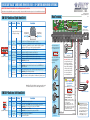
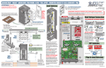
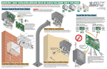
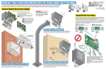
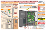
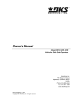
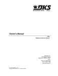
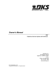
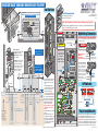
QUICKSTART “BASIC” GUIDELINES FOR MODEL 9500 “FULL OPEN”
Limit Switches
17
16
1
2
5
6
11
13A
13B
13E
25
1 2 3 4
ON
B
1 2 3 4 5 6 7 8
Manual Crank Stored
17
16
11
13A
13B
13E
25
6
5
2
D
See reverse side
ON
Electronic Box
To
Be p M
Le US
ve T
l!
1
Limit LEDs
Auto-Close Timer
D
1
23
Adjust 1 to 23 sec.
Plug-In Loop Detectors
NC
See reverse side to wire main terminal.
20 19 18 17 16 15 14 13 12 11 10 9
SW 1 and 2 are Upside-Down on Circuit Board.
1. Opening Direction
2. ON
3. ON
4. OFF
5. OFF
TIME
6. OFF
DELAY
7. OFF
8. OFF
1A
2A
B
1. OFF
2. OFF
3. OFF
4. OFF
Re-bar
LMT
T
1
EXIT
LOOP
Re-bar
DIP-Switches
ON
Plug-In Loop
Detector
2
4404-010
PE PE
SINGLE Phase
Use only two legs of the
incoming 3-phase power.
Check polarity of Three Phase:
Position the gate half way open.
Hot Hot Hot A
Give open command and while
gate is opening, activate the
115 VAC Output
appropriate limit switch with
your finger. Gate should STOP.
If it does not, activate the other Chassis
208/230/
limit switch. If this STOPS the Ground
gate, AC power wires must be
460 VAC
changed (Reverse the
THREE Phase
High Voltage
connection of any 2 wires and AC Input Wire
re-check limits).
9410
Plug-In Loop
Detector
TIME
DELAY
Re-bar
W
NO
Copyright 2013 DoorKing, Inc. All rights reserved.
9410
V
208/230 VAC
ON
2 ft/s
Chassis
VERIFY Input AC power
Ground
MATCHES your
High
Voltage
specific operator
power BEFORE wiring! AC Input Wire
1 2 3 4
1.5 ft/s
REV SENSE
CLOSE
12”
basic I/O control
REV SENSE
OPEN
12”
SCM series
P7
12”
Speed
Controller
U
P6
Use twelve (12)
1/2” x 3” sleeve
anchors (not
supplied) to
secure operator
to concrete pad.
1.0
1 ft/s
0 ft/s
With power OFF, push and hold the
lock plate down where shown to
adjust the Open and Close limit
nuts.
After adjusting the limit-nuts, be
sure that the lock-plate is engaged
in the slots on the limit-nuts to
prevent them from rotating.
The slow-down limits will move up
or down 3/4 inch. DO NOT remove
the slow-down limit assembly from
the 3/4 inch slot and re-attach it in
the longer slot on the partial open
adjustment rail to gain further
adjustment. This will cause
mechanical damage to the switch
assembly when the operator is
activated.
Turn power ON and activate the gate
operator.
Re-adjust the limit nuts as necessary for full-open and full-close gate
travel. After you are satisfied with
the gate limit settings, the speed
control knob can then be adjusted
to personal preference.
B- B+
PE
EPM
LOOP
1/2
10.5”
L1 L2/N
Min Max
Speed
.5 ft/s
A
Hot
115 VAC Output
Mode
Speed Control
Knob
Hot
HIGH VOLTAGE!
cycle the operator until
the “DIP-Switches” and
the “Limit Switches”
have been adjusted.
Damage could occur to
the gate and operator.
REVERSE
10.5”
Tip: It is recommended that a surge suppressor be installed on the
high voltage power lines.
DANGER
High Voltage AC input power MUST MATCH
the operator specifications or DAMAGE will
occur and VOID the warranty!
P8
3/4”
Conduit
(Sweeps)
EXIT
LOOP
Wire Mesh
12”
REV SENSE
CLOSE
15”
LMT
15”
Concrete Pad
24” depth up to 8,000 lb. gate.
36” depth up to 25,000 lb. gate.
P7
15”
4” Min.
12”
P6
15”
Sleeve
Anchors
12”
Limit Nut
Chain
Tray
3/4” Conduit
2A
Chain
Bracket
Idler Wheels
Chassis
Ground
GATE OPERATOR MUST BE PROPERLY GROUNDED!!
DO NOT power up and
Chain brackets MUST be
mounted so the chain
remains the same height
as it is on the idler wheels!
Chain
Bracket
11”
sed
tU
No
it
im
2 Litch
Sw
Chain Tray Note: Recommended
for longer gates to support the
weight of the chain. DoorKing
offers a chain tray and supporting
brackets in sections to fit any
length gate. (DoorKing P/N
2601-270 10 Ft. section)
Anti-Grounding Plate
CAUTION
Slow-Down Limit
4”
en
Chain brackets MUST align
with idler wheels so chain
stays PARALLEL to gate!
115 VAC Convenience Outlets
A
Op
Push
Pa
High Voltage Connection
DANGER
HIGH VOLTAGE!
Lock-Plate
Partial Open Adjustment Rail
l
rtia
Pedestrians must be supplied with a separate access opening. For safety and installation instructions,
please refer to the installation/owner’s manual.
Push
Chain
Bracket
U.S.A.
Model 9500 is intended for installation only on sliding gates used for vehicles.
-010
4404
1A
120 Glasgow Avenue
Inglewood, California 90301
Power safety and opening devices
that require 115 VAC power.
ft/s
Limit Nut
it
im
1 Litch
Sw
4”
4” minimum from operator chassis to gate.
Mechanical
Disc Brake
Two 115 VAC Convenience Outlets
es
seri l
M contro
SC
I/O
sic
ft/s
2 ft/s
Chain
Bracket
Manual Crank Note:
Model 9555/9556 mechanical disc
brake MUST be disengaged
BEFORE manually operating the
gate (See manual).
1.5
0 ft/s
Slow-Down Limit
”
3/4nduit
o
C
.5
Manual Crank:
refer to manual
for manual gate
operation.
r: 12”
-Ba ” x t.
Re er 12 e pos
4 pncret
co
und
de
ba
1 ft/s
P8
Gro
Mo
REVERSE
ove
B+
0
LOOP
Ab
B-
1 2 3 4 5 6 7 8
36”
L3
00
M
EP
Concrete Pad
56”
Operator MUST be PARALLEL to gate!
L2
L1
8
7
6 5 4 3
2 1
Not included - Refer to the Installation/Owner’s manual AND
Loop Information Manual (available from www.dkaccess.com)
for more information on loops and plug-in loop detectors.
Important Note: DoorKing highly recommends that loops and
loop detectors are installed with this slide gate operator. A loop
detection system will preventing the gate from automatically
opening or closing on a vehicle when it is in the gate’s path.
9500-066-G-3-13
QUICKSTART “BASIC” GUIDELINES FOR MODEL 9500 - DIP-SWITCH AND WIRING REFERENCE
Model 9500 is intended for installation only on sliding gates used for vehicles.
Pedestrians must be supplied with a separate access opening. For safety and installation instructions, please refer to the Installation/Owner’s manual.
Main Terminal
SW 1 DIP-Switches (Right Hand Side)
Setting
Description
NO
Function
U.S.A.
P7
Switch
120 Glasgow Avenue
Inglewood, California 90301
NC
Auxiliary Common
Terminal
3
Exit Loop Port
Output
Full Open Input
OFF Auto-close timer is OFF. Manual input required to close gate.
ON Auto-close timer is ON. Adjustable from 1-23 seconds to close gate.
OFF The output wired to terminal #4 becomes the output from the exit loop detector
plugged into the EXIT Loop port. Used for dual operator application.
ON Normal Setting. Terminal #4 is a normal full open input.
Relay Activation 4-OFF 5-OFF Relay activates and LED is ON when the gate is fully open.
and
4-OFF 5-ON Relay activates and LED is ON when the gate is not closed.
4 and 5
LED Indicator 4-ON 5-OFF Relay activates and LED is ON when the gate is opening and open.
Light Activation
4-ON 5-ON Relay activates and LED is ON when the gate is opening and closing.
6
Warn Before
Operate
7
Reverses Gate
1 2 3 4 5 6 7 8
ON
Stops Gate
8
Quick-Close
Timer Override
OFF Normal Setting. No sound.
ON Internal alarm will sound before gate starts and throughout gate’s cycle.
OFF Normal Setting. Input to terminal #6 and/or reverse loops will REVERSE gate
during CLOSE cycle.
ON Input to terminal #6 and/or reverse loops will STOP gate during CLOSE cycle.
20 19 18 17 16 15 14 13 12 11 10 9
8
7
6 5 4 3
Red Full Open
Note: All stand-alone and
telephone entry devices must
use a separate power source.
Green Close
White Com
3-Button Control Station
ON
Auto-Close
Timer
Opening direction
using OFF setting.
DoorKing ONLY
SW 1 is Upside-Down on Board
SW 1, Switch 3 MUST be ON
except for dual operators or
exit loop partial open
applications.
Important: Controls must be
far enough from the gate so
that the user is prevented
from coming in contact with
the gate while operating the
controls. Outdoor or easily
accessible controls should
have a security feature to
prevent unauthorized use.
OFF Normal Setting. Timer will function normally.
ON Opening gate will stop and begin to close as soon as all reversing inputs (Reverse
loops, photo sensors) are cleared regardless of the distance the gate has opened.
Telephone Entry
“Optional” REVERSE GATE
for Closing Direction
Photo Sensors
Note: After a DIP-switch setting is changed, power must be turned
OFF and then turned back on for the new setting to take affect.
Functions ONLY during gate closing cycle.
1 2 3 4 5 6 7 8
Key Switch
1 2 3 4
ON
SW 2
Upside-Down on Circuit Board.
Switch
Function
1
Self-Test
2
Gate Opens
Uphill
3
4
Setting
#1-Com
#2-Fully opens gate.
Safety Opening Device
#1-Com
#2 or #5-Relay
#3-24 volt
250 mamp. max.
3-Wire Radio Receiver
#1-24 Volt Power Com
#1-Relay Com
#2 or #5-Relay
#3-24 Volt Power
4-Wire Radio Receiver
ON
SW 2 DIP-Switches (Left Hand Side)
2 1
#4 - Full Open
Upside-Down on Circuit Board.
2
Opening direction
using ON setting.
#5 - Partial Open (See manual)
SW 1
Changes the direction the operator
will open/close the gate.
1 2 3 4 5 6 7 8
1
Connect any common
wire to these 2 terminals.
SW 1 is Upside-Down on Board
SW 1, switch 7: After photo sensor beam
gets obstructed:
OFF Setting - REVERSES GATE.
ON Setting - Stops gate then continues
closing when gate is clear (Same function
as UL 325 terminal #2).
Note: The ON setting is used to help
prevent tailgating but the photo sensor
should be wired to the UL 325 terminal #2
when the “stop gate” function is desired,
see manual for more information.
Description
Gate Opens
Downhill
OFF
ON
OFF
ON
OFF
ON
Normal Setting. Normal gate operation.
Self-test mode. Operator MUST be disconnected from gate to run self-test.
Normal Setting. Level gate operation or gate opens DOWNHILL.
MUST be ON if gate opens UPHILL.
Normal Setting. Level gate operation or gate opens UPHILL.
MUST be ON if gate opens DOWNHILL.
Spare
OFF
Leave in the OFF position.
Stand-Alone
Keypad
Com
Stand-Alone
Card Reader
To #4 or #5
#5 Terminal Note: Any opening
device connected to terminal #5 will
open the gate to the partial open
setting. Secondary entrapment
protection devices will also open the
gate to the partial open setting. If the
Inherent Reverse Sensor gets
activated during the close cycle, it
will always fully open the gate.