1
Agilent
N8900 Series Autoranging
System DC Power Supply
Operating and Service Guide
Agilent N8900 Series Autoranging
System DC Power Supply
Operating and Service Guide
This document includes user,service, and programming information for the Agilent N8900 Series Autoranging System
DC Power Supply. If you have feedback on this document, please contact Agilent at www.agilent.com/find/n8900docfeedback.
Preliminary Information
Legal and Safety Information
Models and Options
Specifications and Characteristics
Operating Information
Introduction to the Instrument
Installing the Instrument
Getting Started
Using the Power Supply
Front Panel Menu Reference
SCPI Programming Information
Introduction to the SCPI Language
Commands by Subsystem
Command Quick Reference
SCPI Error Messages
Service Information
Performance Verification
Calibration Procedure
Contact Agilent Technologies
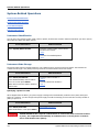
You can contact Agilent Technologies for warranty, service, or technical support.
l
In the United States: (800) 829-4444
l
In Europe: 31 20 547 2111
l
In Japan: 0120-421-345
Use www.agilent.com/find/assist for information on contacting Agilent worldwide, or contact your Agilent Technologies
Representative.
Version 2, updated -XQH 2014
© Copyright Agilent Technologies, Inc. 2013, 2014
Manual part number N8900-90901
2
Agilent N8900 Series Operating and Service Guide
Legal and Safety Information
Legal and Safety Information
Legal Notices
Safety Notices
Safety Symbols
Legal Notices
© Copyright Agilent Technologies, Inc. 2013, 2014
No part of this manual may be reproduced in any form or by any means (including electronic storage and retrieval or
translation into a foreign language) without prior agreement and written consent from Agilent Technologies, Inc. as
governed by United States and international copyright laws.
Agilent Technologies, Inc.
550 Clark Drive, Suite 101
Budd Lake, New Jersey 07828 USA
Software and Documentation Revisions
For the latest firmware revision go to the product page at www.agilent.com/find/N8900.
You can download the latest version of this document at www.agilent.com/find/n8900-doc. The latest version is also
available for mobile devices at www.agilent.com/find/n8900-mobilehelp.
The hardware and/or software described in this document are furnished under a license and may be used or copied only
in accordance with the terms of such license.
Warranty
The material contained in this document is provided "as is," and is subject to being changed, without notice, in future
editions. Further, to the maximum extent permitted by applicable law, Agilent disclaims all warranties, either express
or implied, with regard to this manual and any information contained herein, including but not limited to the implied
warranties of merchantability and fitness for a particular purpose. Agilent shall not be liable for errors or for incidental or
consequential damages in connection with the furnishing, use, or performance of this document or of any information
contained herein. Should Agilent and the user have a separate written agreement with warranty terms covering the
material in this document that conflict with these terms, the warranty terms in the separate agreement shall control.
Certification
Agilent Technologies certifies that this product met its published specifications at time of shipment from the factory. Agilent Technologies further certifies that its calibration measurements are traceable to the United States National Institute of Standards and Technology, to the extent allowed by the Institute's calibration facility, and to the calibration
facilities of other International Standards Organization members
Restricted Rights Legend
If software is for use in the performance of a U.S. Government prime contract or subcontract, Software is delivered and
licensed as "Commercial computer software" as defined in DFAR 252.227-7014 (June 1995), or as a "commercial
Agilent N8900 Series Operating and Service Guide
3
Legal and Safety Information
item" as defined in FAR 2.101(a) or as "Restricted computer software" as defined in FAR 52.227-19 (June 1987) or any
equivalent agency regulation or contract clause. Use, duplication or disclosure of Software is subject to Agilent Technologies’ standard commercial license terms, and non-DOD Departments and Agencies of the U.S. Government will
receive no greater than Restricted Rights as defined in FAR 52.227-19(c)(1-2) (June 1987). U.S. Government users
will receive no greater than Limited Rights as defined in FAR 52.227-14 (June 1987) or DFAR 252.227-7015 (b)(2)
(November 1995), as applicable in any technical data.
Technical Support
If you have questions about your shipment, or if you need information about warranty, service, or technical support,
contact Agilent Technologies.
Safety Notices
The following general safety precautions must be observed during all phases of operation of this instrument. Failure to
comply with these precautions or with specific warnings or instructions elsewhere in this manual violates safety standards of design, manufacture, and intended use of the instrument. Agilent Technologies assumes no liability of the customer’s failure to comply with the requirements.
HAZARDOUS VOLTAGES All models generate voltages in excess of 60 VDC, with some
models rated at up to 1,500 VDC! Ensure that all instrument connections, load wiring,
and load connections are either insulated or covered so that no accidental contact
with lethal output voltages can occur.
General
The equipment is for industrial use. It is not applicable for IT mains supply systems.
Equipment operators are subject to all applicable safety regulations. Along with the warning and safety notices in this
manual, all relevant safety, accident prevention, and environmental regulations must also be followed. In particular,
the operators of the equipment:
l
Must be informed of the relevant safety requirements.
l
Must have read and understood the operating manual before using the equipment.
l
Must use the designated and recommended safety equipment.
Do not use this product in any manner not specified by the manufacturer. The protective features of this product may
be impaired if it is used in a manner not specified in the operating instructions.
Environmental Conditions
Environmental condition are described under Common Characteristics.
Before Applying Power
Verify that all safety precautions are taken. All connections must be made with the unit turned off, and must be performed by qualified personnel who are aware of the hazards involved. Improper actions can cause fatal injury as well as
equipment damage.
4
Agilent N8900 Series Operating and Service Guide
Legal and Safety Information
Note the instrument's external markings described under "Safety Symbols". Only operate the product at the rated
mains voltage and phase as stipulated on the input label.
Ground the Instrument
This product is provided with protective earth terminals. To minimize shock hazard, the instrument must be connected
to the AC mains through a grounded power cable, with the ground wire firmly connected to an electrical ground (safety
ground) at the power outlet. Any interruption of the protective (grounding) conductor or disconnection of the protective earth terminal will cause a potential shock hazard that could result in injury or death.
External Voltage Sources
Do not connect voltage sources to the output of the power supply with voltage ratings that are greater than the nominal voltage rating of the supply. Under no circumstances can you connect an external voltage with reversed polarity to
the output terminal. Equipment damage will result.
Do Not Operate in an Explosive Atmosphere.
Do not operate the instrument in the presence of flammable gases or fumes.
Do Not Remove the Instrument Cover
Only qualified, service-trained personnel who are aware of the hazards involved should remove instrument covers.
Always disconnect the power cable and any external circuits before removing the instrument cover.
Do Not Modify the Instrument
Do not install substitute parts or perform any unauthorized modification to the product. Return the product to an Agilent Sales and Service Office for service and repair to ensure that safety features are maintained.
Fuses
The instrument contains internal fuses, which are not customer accessible.
In Case of Damage
Instruments that are not functioning correctly, appear damaged or defective should be made inoperative and secured
against unintended operation until they can be repaired by qualified service personnel.
A WARNING notice denotes a hazard. It calls attention to an operating procedure, practice, or the like
that, if not correctly performed or adhered to, could result in personal injury or DEATH. Do not proceed
beyond a WARNING notice until the indicated conditions are fully understood and met.
Agilent N8900 Series Operating and Service Guide
5
Legal and Safety Information
A CAUTION notice denotes a hazard. It calls attention to an operating procedure, practice, or the like that, if not correctly performed or adhered to, could result in damage to the product or loss of important data. Do not proceed beyond
a CAUTION notice until the indicated conditions are fully understood and met.
Safety Symbols
Direct current
Alternating current
Frame or chassis terminal
Standby supply. Unit is not completely disconnected from AC mains when switch is off.
Caution, risk of electric shock
Caution, refer to accompanying documents
Earth ground terminal
The CE mark is a registered trademark of the European Community.
The TUV mark is a registered trademark of the European community.
The C-tick mark is a registered trademark of the Spectrum Management Agency of
Australia. This signifies compliance with the Australian EMC Framework regulations
under the terms of the Radio Communications Act of 1992.
South Korean Class A EMC Declaration
This equipment is Class A suitable for professional use and is for use in electromagnetic
environments outside of the home.
6
Agilent N8900 Series Operating and Service Guide
Legal and Safety Information
Contains one or more of the 6 hazardous substances above the maximum concentration value (MCV), 40 Year EPUP.
ISM1-A
This text indicates that the instrument is an Industrial Scientific and Medical Group 1
Class A product (CISPER 11, Clause 4).
ICES/NMB001
This text indicates product compliance with the Canadian Interference- Causing Equipment Standard (ICES-001).
Agilent N8900 Series Operating and Service Guide
7
Models and Options
Models and Options
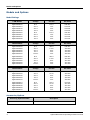
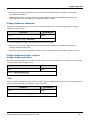
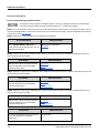
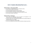
Model Ratings
5 kW Models
Voltage
Current
AC mains
Agilent N8920A
Agilent N8921A
Agilent N8923A
Agilent N8924A
80 V
200 V
500 V
750 V
170 A
70 A
30 A
20 A
208 VAC
208 VAC
208 VAC
208 VAC
Agilent N8940A
Agilent N8941A
Agilent N8943A
Agilent N8944A
80 V
200 V
500 V
750 V
170 A
70 A
30 A
20 A
400 VAC
400 VAC
400 VAC
400 VAC
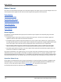
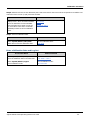
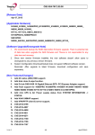
10 kW Models
Voltage
Current
AC mains
Agilent N8925A
Agilent N8926A
Agilent N8928A
Agilent N8929A
Agilent N8930A
80 V
200 V
500 V
750 V
1000 V
340 A
140 A
60 A
40 A
30 A
208 VAC
208 VAC
208 VAC
208 VAC
208 VAC
Agilent N8945A
Agilent N8946A
Agilent N8948A
Agilent N8949A
Agilent N8950A
80 V
200 V
500 V
750 V
1000 V
340 A
140 A
60 A
40 A
30 A
400 VAC
400 VAC
400 VAC
400 VAC
400 VAC
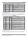
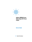
15 kW Models
Voltage
Current
AC mains
Agilent N8931A
Agilent N8932A
Agilent N8934A
Agilent N8935A
Agilent N8937A
80 V
200 V
500 V
750 V
1500 V
510 A
210 A
90 A
60 A
30 A
208 VAC
208 VAC
208 VAC
208 VAC
208 VAC
Agilent N8951A
Agilent N8952A
Agilent N8954A
Agilent N8955A
Agilent N8957A
80 V
200 V
500 V
750 V
1500 V
510 A
210 A
90 A
60 A
30 A
400 VAC
400 VAC
400 VAC
400 VAC
400 VAC
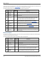
Accsssories/Options
Accessory/Option Number
Agilent N8958A
8
Description
Rack Mount Kit
Agilent N8900 Series Operating and Service Guide
Specifications and Characteristics
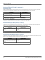
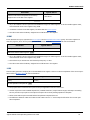
Specifications and Characteristics
Specifications
Supplemental Characteristics
Common Characteristics
Autoranging Characteristics
Dimension Diagrams
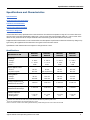
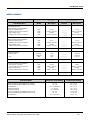
Unless otherwise noted, specifications are warranted over the ambient temperature range of 0°C to 45°C after a 30minute warm-up period. Specifications apply from >2% to 100% of the rated voltage and from >1% to 100% of the
rated current, measured at the output terminals with local sensing (sense terminals not connected).
Supplemental characteristics are not warranted but are descriptions of performance determined either by design or by
type testing. All supplemental characteristics are typical unless otherwise noted.
Specifications and characteristics are subject to change without notice.
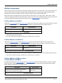
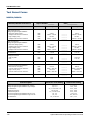
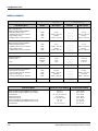
Specifications
N8920A/
N8940A
N8921A/
N8941A
N8923A/
N8943A
N8924A/
N8944A
0 - 80 V
0 - 170 A
5 kW
0 - 200 V
0 - 70 A
5 kW
0 - 500 V
0 - 30 A
5 kW
0 - 750 V
0 - 20 A
5 kW
Output ripple & noise1
CV rms:
CV peak-to-peak:
16 mV
200 mV
40 mV
375 mV/300 mV
70 mV
350 mV
200 mV
800 mV
Load regulation
Voltage:
Current:
40 mV
255 mA
100 mV
105 mA
250 mV
45 mA
375 mV
30 mA
Voltage programming &
measurement accuracy2
≤ 80 mV
≤ 200 mV
≤ 500 mV
≤ 750 mV
Current programming &
measurement accuracy2
≤ 340 mA
≤ 140 mA
≤ 60 mA
≤ 40 mA
≤ 1.5 ms
0.8 V
≤ 1.5 ms
2V
≤ 1.5 ms
5V
≤ 1.5 ms
7.5 V
Specification 5 kW
DC Ratings
Voltage:
Current:
Power:
Transient response3
Recovery Time:
Settling band:
1From 20 Hz to 300 kHz for rms noise; from 20 Hz to 20 MHz for peak-to-peak noise
2Accuracy specifications are warranted at 23°C ±5°C
3Time to recover to within the settling band following a load change from 10% to 90% of full load
Agilent N8900 Series Operating and Service Guide
9
Specifications and Characteristics
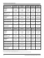
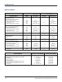
N8925A/
N8945A
N8926A/
N8946A
N8928A/
N8948A
N8929A/
N8949A
N8930A/
N8950A
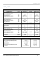
DC Ratings
Voltage:
Current:
Power:
0 - 80 V
0 - 340 A
10 kW
0 - 200 V
0 - 140 A
10 kW
0 - 500 V
0 - 60 A
10 kW
0 - 750 V
0 - 40 A
10 kW
0 - 1000 V
0 - 30 A
10 kW
Output ripple & noise1
CV rms:
CV peak-to-peak:
25 mV
320 mV
40 mV
375 mV/300 mV
70 mV
350 mV
200 mV
800 mV
350 mV
1600 mV
Load regulation
Voltage:
Current:
40 mV
510 mA
100 mV
210 mA
250 mV
90 mA
375 mV
60 mA
500 mV
53 mA/45 mA
Voltage programming &
measurement accuracy2
≤ 80 mV
≤ 200 mV
≤ 500 mV
≤ 750 mV
≤1V
Current programming &
measurement accuracy2
≤ 680 mA
≤ 280 mA
≤ 120 mA
≤ 80 mA
≤ 60 mA
≤ 1.5 ms
0.8 V
≤ 1.5 ms
2V
≤ 1.5 ms
5V
≤ 1.5 ms
7.5 V
≤ 1.5 ms
10 V
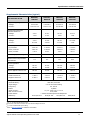
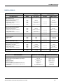
N8931A/
N8951A
N8932A/
N8952A
N8934A/
N8954A
N8935A/
N8955A
N8937A/
N8957A
DC Ratings
Voltage:
Current:
Power:
0 - 80 V
0 - 510 A
15 kW
0 - 200 V
0 - 210 A
15 kW
0 - 500 V
0 - 90 A
15 kW
0 - 750 V
0 - 60 A
15 kW
0 - 1500 V
0 - 30 A
15 kW
Output ripple & noise1
CV rms:
CV peak-to-peak:
25 mV
320 mV
40 mV
375 mV/300 mV
70 mV
350 mV
200 mV
800 mV
400 mV
2400 mV
Load regulation
Voltage:
Current:
40 mV
765 mA
100 mV
315 mA
250 mV
135 mA
375 mV
90 mA
750 mV
53 mA/45 mA
Voltage programming &
measurement accuracy2
≤ 80 mV
≤ 200 mV
≤ 500 mV
≤ 750 mV
≤ 1.5 V
Current programming &
measurement accuracy2
≤ 1.1 A
≤ 420 mA
≤ 180 mA
≤ 120 mA
≤ 60 mA
≤ 1.5 ms
0.8 V
≤ 1.5 ms
2V
≤ 1.5 ms
5V
≤ 1.5 ms
7.5 V
≤ 1.5 ms
15 V
Specification 10 kW
Transient response3
Recovery Time:
Settling band:
Specification 15 kW
Transient response3
Recovery Time:
Settling band:
1From 20 Hz to 300 kHz for rms noise; from 20 Hz to 20 MHz for peak-to-peak noise
2Accuracy specifications are warranted at 23°C ±5°C
3Time to recover to within the settling band following a load change from 10% to 90% of full load
10
Agilent N8900 Series Operating and Service Guide
Specifications and Characteristics
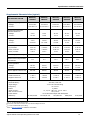
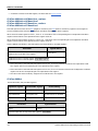
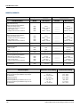
Supplemental Characteristics (typical)
N8920A/
N8940A
N8921A/
N8941A
N8923A/
N8943A
N8924A/
N8944A
0 to 81.6 V
0 to 173.4 A
0 to 204 V
0 to 71.4 A
0 to 510 V
0 to 30.6 A
0 to 765 V
0 to 20.4 A
Programming and Measurement Resolution
Voltage:
Current:
4 mV
7 mA
9 mV
3 mA
21 mV
2 mA
31 mV
1 mA
Temperature Coefficient1
Voltage:
Current:
4 mV
8.5 mA
10 mV
3.5 mA
25 mV
1.5 mA
37.5 mV
1 mA
Output response time2
Up, full load:
Down, full load:
Down, no load:
≤ 30 ms
≤ 80 ms
≤ 30 s
≤ 30 ms
≤ 80 ms
≤10 s
≤ 30 ms
≤ 80 ms
≤10 s
≤ 30 ms
≤ 80 ms
≤10 s
Over-voltage protect range
0 to 88 V
0 to 220 V
0 to 550 V
0 to 825 V
2V
5V
10 V
18 V
Source regulation 3
Voltage:
Current:
16 mV
85 mA
40 mV
35 mA
100 mV
15 mA
150 mV
10 mA
Output ripple & noise CC rms
80 mA
22 mA
16 mA
16 mA
Version 2
+ 400 V
± 400 V
Version 2
+ 600 V
± 400 V
Version 2
+ 1000 V
± 725 V
Version 2
+ 1000 V
± 725 V
Characteristic 5 kW
Programming Range
Voltage:
Current:
Remote sense compensation
per load lead
Output Terminal Isolation 4
Positive Terminal:
Negative Terminal:
AC Input
Nominal Rating:
Input Range:
Frequency:
Phase:
Input Current:
Max. Inrush Current:
Power Factor:
Efficiency:
208 VAC / 400 VAC
± 10 % of nominal rating
45 - 65 Hz
3-phase
L2, L3 - 32 A / L2, L3 - 16 A
41 A / 28 A
> 0.99 at nominal input and rated power
87.5%/91.5%
90%/91.5%
91%/93.5%
88%/90%
Weight
≤18.5 kg (41 lbs) / ≤17 kg (38 lbs)
1Per °C, at rated voltage and current
2From 10% to 90% or from 90% to 10% of total voltage excursion
3+/-10% of nominal AC input rating
4Refer to Manual Updates for additional information
Agilent N8900 Series Operating and Service Guide
11
Specifications and Characteristics
Supplemental Characteristics (typical)
N8925A/
N8945A
N8926A/
N8946A
N8928A/
N8948A
N8929A/
N8949A
N8930A/
N8950A
0 to 81.6 V
0 to 346.8 A
0 to 204 V
0 to 142.8 A
0 to 510 V
0 to 61.2 A
0 to 765 V
0 to 40.8 A
0 to 1020 V
0 to 30.6 A
Programming and Measurement Resolution
Voltage:
Current:
4 mV
14 mA
9 mV
6 mA
21 mV
3 mA
31 mV
2 mA
41 mV
2 mA
Temperature Coefficient1
Voltage:
Current:
4 mV
17 mA
10 mV
7 mA
25 mV
3 mA
37.5 mV
2 mA
50 mV
1.5 mA
≤ 30 ms
≤ 80 ms
≤ 30 s / 40 s
≤ 30 ms
≤ 80 ms
≤10 s
≤ 30 ms
≤ 80 ms
≤10 s
≤ 30 ms
≤ 80 ms
≤10 s
≤ 30 ms
≤ 80 ms
≤10 s
0 to 88 V
0 to 220 V
0 to 550 V
0 to 825 V
0 - 1100 V
2V
5V
10 V
18 V
22 V
Source regulation 3
Voltage:
Current:
16 mV
170 mA
40 mV
70 mA
100 mV
30 mA
150 mV
20 mA
200 mV
15 mA
Output ripple & noise CC rms
160 mA
44 mA
32 mA
32 mA
22 mA
Version 2
+ 400 V
± 400 V
Version 2
+ 600 V
± 400 V
Version 2
+ 1000 V
± 725 V
Version 2
+ 1000 V
± 725 V
Version 2
+ 1000 V
± 725 V
Characteristic 10 kW
Programming Range
Voltage:
Current:
Output response time2
Up, full load:
Down, full load:
Down, no load:
Over-voltage protect range
Remote sense compensation
per load lead
Output Terminal Isolation 4
Positive Terminal:
Negative Terminal:
AC Input
Nominal Rating:
Input Range:
Frequency:
Phase:
Input Current:
Max. Inrush Current:
Power Factor:
Efficiency:
Weight
87.5%/89.5%
208 VAC / 400 VAC
± 10 % of nominal rating
45 - 65 Hz
3-phase
L1 - 56 A; L2, L3 - 32 A / L1 - 28 A; L2, L3 - 16 A
97 A / 49 A
> 0.99 at nominal input and rated power
89.5%/91.5%
91%/91%
88%/90%
91%/93.5%
≤ 27 kg (60 lbs) / ≤ 25.5 kg (55 lbs)
1Per °C, at rated voltage and current
2From 10% to 90% or from 90% to 10% of total voltage excursion
3+/-10% of nominal AC input rating
4Refer to Manual Updates for additional information
12
Agilent N8900 Series Operating and Service Guide
Specifications and Characteristics
Supplemental Characteristics (typical)
N8931A/
N8951A
N8932A/
N8952A
N8934A/
N8954A
N8935A/
N8955A
N8937A/
N8957A
0 to 81.6 V
0 to 520.2 A
0 to 204 V
0 to 214.2 A
0 to 510 V
0 to 91.8 A
0 to 765 V
0 to 61.2 A
0 to 1530 V
0 to 30.6 A
Programming and Measurement Resolution
Voltage:
Current:
4 mV
21 mA
9 mV
9 mA
21 mV
4 mA
31 mV
3 mA
61 mV
2 mA
Temperature Coefficient1
Voltage:
Current:
4 mV
25.5 mA
10 mV
10.5 mA
25 mV
4.5 mA
37.5 mV
3 mA
75 mV
1.5 mA
Output response time2
Up, full load:
Down, full load:
Down, no load:
≤ 30 ms
≤ 80 ms
≤ 30 s
≤ 30 ms
≤ 80 ms
≤10 s
≤ 30 ms
≤ 80 ms
≤10 s
≤ 30 ms
≤ 80 ms
≤10 s
≤ 30 ms
≤ 80 ms
≤10 s
Over-voltage protect range
0 to 88 V
0 to 220 V
0 to 550 V
0 to 825 V
0 - 1650 V
2V
5V
10 V
18 V
30 V
Source regulation 3
Voltage:
Current:
16 mV
255 mA
40 mV
105 mA
100 mV
45 mA
150 mV
30 mA
300 mV
15 mA
Output ripple & noise CC rms
240 mA
66 mA
48 mA
48 mA
26 mA
Version 2
+ 400 V
± 400 V
Version 2
+ 600 V
± 400 V
Version 2
+ 1000 V
± 725 V
Version 2
+ 1000 V
± 725 V
Version 3
+ 1500 V
± 1000 V
Characteristic 15 kW
Programming Range
Voltage:
Current:
Remote sense compensation
per load lead
Output Terminal Isolation 4
Positive Terminal:
Negative Terminal:
AC Input
Nominal Rating:
Input Range:
Frequency:
Phase:
Input Current:
Max. Inrush Current:
Power Factor:
Efficiency:
87.5%/89.5%
Weight
208 VAC / 400 VAC
± 10 % of nominal rating
45 - 65 Hz
3-phase
L1, L2, L3 - 56 A / L1, L2, L3 - 28 A
97 A / 49 A
> 0.99 at nominal input and rated power
89.5%/91.5%
91%/93.5%
88%/90%
91%/93%
≤ 35.5 kg (78 lbs) / ≤ 32 kg (70 lbs)
1Per °C, at rated voltage and current
2From 10% to 90% or from 90% to 10% of total voltage excursion
3+/-10% of nominal AC input rating
4Refer to Manual Updates for additional information
Agilent N8900 Series Operating and Service Guide
13
Specifications and Characteristics
Common Characteristics
Characteristic
All Models
Command Response Time:
< 25 ms
Savable States:
10
Analog Programming
Input range:
Accuracy:
Input impedance:
0 to 5 V or 0 to 10 V (selectable)
Specified instrument accuracy ±0.2% of rating
150 kΩ (referenced to ground)
Computer Interfaces
LXI Core 2011:
USB:
GPIB:
Language:
10/100 Base-T Ethernet (Sockets, VXI-11 protocol, Web user interface)
USB 2.0 (USB-TMC488)
GPIB IEEE 488
SCPI - 1993, IEEE 488.2 compliant
Regulatory Compliance:
EMC:
Safety:
Complies with European EMC Directive for test and measurement products
Complies with Australian standard and carries C-Tick mark
This ISM device complies with Canadian ICES-001
Cet appareil ISM est conforme à la norme NMB-001 du Canada
Complies with European Low Voltage Directive and carries the CE-marking.
Conforms to US and Canadian safety regulations.
Not applicable for IT mains supply systems
Declarations of Conformity for this product may be downloaded from the
Web. Go to http://regulations.corporate.agilent.com and click on “Declarations of Conformity.”
Environmental
Operating environment:
Temperature range:
Relative humidity:
Altitude:
Storage temperature:
Indoor use, installation category II (for AC input), pollution degree 2
0°C to 45°C
80% or less (non-condensing)
Up to 2000 meters
-20°C to 70°C
Acoustic Noise - 5 kW models
At maximum fan speed:
At idle:
76 dBA max. for 208 VAC input; 57 dBA max. for 400 VAC input
55 dBA max. for 208 VAC input; 48 dBA max. for 400 VAC input
Acoustic Noise - 10 kW models
At maximum fan speed:
At idle:
77 dBA max. for 208 VAC input; 62 dBA max. for 400 VAC input
55 dBA max. for 208 VAC input; 51 dBA max. for 400 VAC input
Acoustic Noise - 15 kW models
At maximum fan speed:
At idle:
79 dBA max. for 208 VAC input; 72.6 dBA max. for 400 VAC input
56 dBA max. for 208 VAC input; 52 dBA max. for 400 VAC input
14
Agilent N8900 Series Operating and Service Guide
Specifications and Characteristics
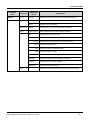
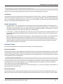
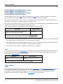
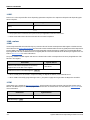
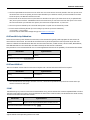
Autoranging Characteristics
5 kW
Models
N8920A
N8940A
N8921A
N8941A
N8923A
N8943A
N8924A
N8944A
V1
80 V
200 V
500 V
750 V
I1
62.5 A
25 A
10 A
6.667 A
V2
29.4 V
71.43 V
166.67 V
250 V
I2
170 A
70 A
30 A
20 A
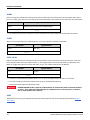
10 kW
Models
N8925A
N8945A
N8926A
N8946A
N8928A
N8948A
N8929A
N8949A
V1
80 V
200 V
500 V
750 V
1000 V
I1
125 A
50 A
20 A
13.33 A
10 A
V2
29.4 V
71.43 V
166.67 V
250 V
333.33 V
I2
340 A
140 A
60 A
40 A
30 A
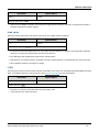
15 kW
Models
N8931A
N8951A
N8932A
N8952A
N8934A
N8954A
N8935A
N8955A
V1
80 V
200 V
500 V
750 V
1500 V
I1
187.5 A
75 A
30 A
20 A
10 A
V2
29.4 V
71.43 V
166.67 V
250 V
500 V
I2
510 A
210 A
90 A
60 A
30 A
Agilent N8900 Series Operating and Service Guide
N8930A
N8950A
N8937A
N8957A
15
Specifications and Characteristics
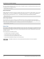
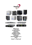
Dimension Diagrams
16
Agilent N8900 Series Operating and Service Guide
Operating Information
Operating Information
Introduction to the Instrument
Installing the Instrument
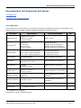
Getting Started
Using the Power Supply
Agilent N8900 Series Operating and Service Guide
17
Introduction to the Instrument
Introduction to the Instrument
Agilent N8900 Series at a Glance
Front Panel at a Glance
Front Panel Display at a Glance
Front Panel Keys at a Glance
Rear Panel at a Glance
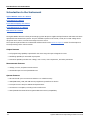
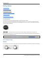
The Agilent N8900 Series is a family of autoranging system DC power supplies with performance and features that are
optimized for automated test systems. They are available in power levels of 5 kW, 10 kW, and 15 kW. Voltage levels
range from 80 to 1500 V. Current levels range from 20 to 510 A.
The output and system features are described as follows. Refer to the Models and Options section for a description of
the output ratings of the various models.
Output features
l
Full programming capability is provided for the entire range of output voltage and current
l
Paralleling capability for increased output power
l
Protection capability includes over-voltage, over-current, over-temperature, and other protections
Measurement features
l
Voltage, current, and power measurements
l
Combined output current of paralleled units
System features
l
Save and recall up to 10 instrument states in non-volatile memory
l
GPIB (IEEE-488), LAN, and USB remote programming interfaces are built in
l
Front panel menu setup for GPIB and LAN parameters
l
LXI Core 2011 compliant, including a built-in Web server
l
SCPI (Standard Commands for Programmable Instruments) compatibility
18
Agilent N8900 Series Operating and Service Guide
Introduction to the Instrument
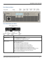
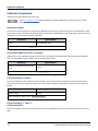
Front Panel at a Glance
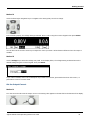
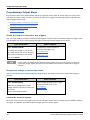
Front Panel Display at a Glance
Output voltage and current
Displays the actual output voltage and current.
Connection status
A = analog programming is enabled
M = the paralleled unit is configured as the master
S = the paralleled unit is configured as a slave
Operating status
Indicates one of the following:
OFF = the output is off
CV = the output is in constant voltage mode
CC = the output is in constant current mode
CP = the output is limited by the power limit boundary
OV = the output is disabled by the over-voltage protection
OC = the output is disabled by the over-current protection
OT = the output is disabled by the over-temperature protection
INH = the output is disabled because of a signal from the analog control port
PF = the output is disabled because of a low voltage on the AC mains
MSP = the output is disabled by the master/slave protection
UNR = the output is unregulated
Agilent N8900 Series Operating and Service Guide
19
Introduction to the Instrument
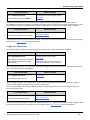
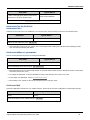
Voltage and Current settings
Displays the programmed voltage and current settings.
Interface status
Indicates the following remote interface activity:
Err = an error has occurred (press Error key to display error message)
Lan = the LAN is connected and has been configured
IO = there is activity on one of the remote interfaces
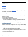
Front Panel Keys at a Glance
The AC line switch turns the unit on or off (off = 0). The indicator above the
On/Off switch shows the display status. Green indicates normal operation.
Amber indicates that the display is in screen saver mode. It is also on during
the boot-up process. Press any key to exit screen saver mode.
The system keys access the following front panel meter and command
menus:
Meter returns the display to metering mode. Repeatedly press this key to
cycle through the following measurement functions:
Voltage, Current
Voltage, Power
Voltage, Current, Power
Menu accesses the command menu.
Function key is reserved for future use.
Back backs out of a menu without activating any changes.
Help accesses information about the displayed menu control.
Error displays any error messages in the error queue.
The navigation keys do the following:
Arrows let you move around in the command menus.
Select lets you make a selection in the command menus. It also lets you
enter edit mode for editing the numeric parameters.
The output keys do the following:
On/Off enables or disables the output.
Voltage lets you change the voltage setting.
Current lets you change the current setting.
20
Agilent N8900 Series Operating and Service Guide
Introduction to the Instrument
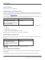
The numeric entry keys do the following:
The 0 through 9 keys enter numbers.
The (.) key is the decimal point.
The – key is used to enter a minus sign.
The up/down arrow keys increment or decrement voltage or current settings.
They also select letters in alphabetic entry fields.
The E key enters an exponent. Add the value to the right of the E.
The back arrow key deletes digits as it backspaces over them.
The Enter key enters a value. If you exit a field without pressing the Enter
key, the value is ignored.
Rear Panel at a Glance
GPIB
GPIB interface connector
LAN
LAN interface connector
Sharing
Current sharing connections - for parallel operation
+/–Sense
Remote sense connections (if not used, local sensing is internally connected)
–Output; +Output
Negative and positive output terminals
AC input
AC line input
USB
USB interface connector
Analog
Analog connector - for analog control
Master/Slave (Group)
Master/slave connectors - for grouping paralleled units
For electrical shock protection, always connect the AC input earth ground terminal.
Agilent N8900 Series Operating and Service Guide
21
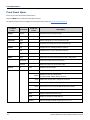
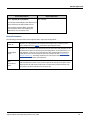
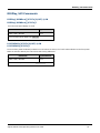
Front Panel Menu
Front Panel Menu
This is an overview of the front-panel menus.
Press the Menu key to access the front panel menus.
For a brief tutorial on how to navigate the front panel menu, refer to Use the front panel menu.
1st Menu
Level
Output
Transient
Protect
States
System
2nd Level
3rd & 4th
Levels
Voltage
Programs output voltage settings
Current
Programs output current settings
Mode
Selects voltage and current transient modes
Step
Programs the voltage and current step settings
OVP
Configures over-voltage protection settings
OCP
Configures over-current protection settings
Clear
Clears protection conditions and displays output status
Reset
Resets all instrument settings to the reset (*RST) state
SaveRecall
Saves and recalls instrument settings
PowerOn
Selects the power-on instrument state
IO
LAN
Displays LAN commands
Settings
Modify
Apply
Cancel
Reset
Defaults
22
Description
View the currently active network settings
Modify the network configuration
(IP, Name, DNS, WINS, mDNS, Services)
Applies the configuration changes and restarts
Cancels the configuration changes
Performs an LXI LCI reset of LAN settings and restarts
Resets the network to the as-shipped defaults and restarts
USB
Displays USB identification string
GPIB
Display or change the GPIB address
Analog
Sets the analog interface amplitude (5 V or 10 V)
Agilent N8900 Series Operating and Service Guide
Front Panel Menu
1st Menu
Level
System
2nd Level
Group
3rd & 4th
Levels
Description
Function
Defines the function of each unit in the paralleled group
Master
Displays the configured slave addresses
Slave
Specifies the slave address
Preferences
Display
Configures the screen saver and wake on IO timer
Admin
Login/Logout
Enter a password to access the Admin functions
Cal
Displays calibration commands
Voltage
Calibrates voltage programming and measurement
Current
Calibrates current programming and measurement
Count
View the calibration count
Date
View and modify the calibration date
Save
Saves the calibration data
IO
Enables/disable the LAN, USB, and GPIB
Sanitize
Performs NISPOM secure erase of all user data
Update
Password protect firmware update
Password
Changes the admin password
About
Agilent N8900 Series Operating and Service Guide
Displays model, output ratings, serial number, and firmware
23
Installing the Instrument
Installing the Instrument
Before Installation or Use
AC Mains Connections
Single Unit Connections
Multiple Unit Connections
Analog Port Connections
Interface Connections
24
Agilent N8900 Series Operating and Service Guide
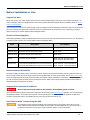
Before Installation or Use
Before Installation or Use
Inspect the Unit
When you receive your power supply, inspect it for any obvious damage that may have occurred during shipment. If
there is damage, notify the shipping carrier and nearest Agilent Sales and Support Office immediately. Refer to www.agilent.com/find/assist.
Until you have checked out the power supply, save the shipping carton and packing materials in case the unit has to be
returned. Check the list below and verify that you have received these items with your unit. If anything is missing,
please contact your nearest Agilent Sales and Support Office.
Check for Items Supplied
Before getting started, check the following list and verify that you have received these items with your unit. If anything
is missing, please contact your nearest Agilent Sales and Support Office.
Item
Description
Part Number
DC covers
Safety covers for DC output terminals
5003-2051
2 position plug
Connector plug for Sharing terminals
5003-2038
4 position plug
Connector plug for Sense terminals
5003-2037
AC plug
Connector plug for AC input
5003-2053 for 400 VAC inputs
5003-2091 for 208 VAC inputs
Hardware Kit
1-set mounting hardware for low current terminals
1-set mounting hardware for high current terminals
5003-2089 for ≥ 500 VAC outputs
5003-2090 for < 500 VAC outputs
Review Safety Information
This power supply is a Safety Class 1 instrument, which means it has a protective earth terminal. That terminal must
be connected to earth ground through a power source equipped with an earth ground. Refer to the Safety Notices section at the beginning of this guide for general safety information. Before installation or operation, check the power supply and review this guide for safety warnings and instructions. Safety warnings for specific procedures are located at
appropriate places throughout this guide.
Observe Environmental Conditions
Do not operate the instrument in the presence of flammable gases or fumes.
The environmental conditions of the power supply are documented under Specifications. Basically, the unit should only
be operated indoors in a controlled environment. Do not operate the unit in areas where the ambient temperature
exceeds +45 degrees Celsius. This applies for rack-mounting as well as for bench use.
Use Caution when Transporting the Unit
Two people are required when handling units. Because of the unit’s weight, do not lift or move it
alone. Moving by hand should be avoided where possible. If unavoidable, lift only the instrument’s
chassis; do not lift the unit using the exterior handles, knobs, or output terminals.
Agilent N8900 Series Operating and Service Guide
25
Before Installation or Use
Provide Adequate Air Flow
Do not block the air intake at the front, or the exhaust at the rear of the unit.
The dimensions of your power supply, an outline diagram, and airflow direction are given under Dimension Diagrams.
Fans cool the power supply by drawing air through the front and exhausting it out the back. Allows at least 8 inches (20
cm) of space at the front and back of the unit for adequate air circulation.
26
Agilent N8900 Series Operating and Service Guide
AC Mains Connections
AC Mains Connections
Phase Balancing with Multiple Units
Power Cables
AC Mains Phase Distribution
SHOCK HAZARD The instrument requires a chassis ground connection through a separate conductor. Be certain that the AC mains includes an earth ground connection.
AC mains connections must be made by a qualified electrician who is knowledgeable
about 3-phase mains circuits and all applicable safety standards and requirements.
400 VAC, 3-phase
5 kW units only
400 VAC, 3-phase
10 kW units only
400 VAC, 3-phase
15 kW units only
Agilent N8900 Series Operating and Service Guide
27
AC Mains Connections
208 VAC, 3-phase
5 kW units only
208 VAC, 3-phase
10 kW units only
208 VAC, 3-phase
15 kW units only
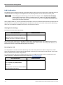
Note that either delta-type or Y-type AC mains distribution can be used, provided that the correct line-to-line voltage is
applied.
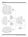
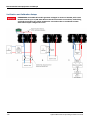
Phase Balancing with Multiple Units
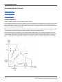
The previous figures illustrate the phase current distribution. The N8900 power supplies can have from one to three
internal 5.6 kW power blocks, each of which is connected across a separate phase of the 3-phase AC mains. For 5 kW
and 10 kW units this will result in a current imbalance when installing one or two units. Installing three units will result
in a balanced current distribution. For 15 kW units, there is no current imbalance, as all phases draw approximately the
same current.
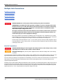
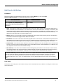
The following figures illustrate how to install three 5 kW units or three 10 kW units in order to obtain a balanced current
draw on the 3-phase AC mains.
28
Agilent N8900 Series Operating and Service Guide
AC Mains Connections
5 kW, 208 VAC and 400 VAC,
phase balancing scheme
10 kW, 208 VAC and 400 VAC,
phase balancing scheme
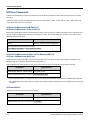
Power Cables
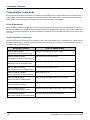
An AC mains power cable is not provided with the unit. Refer to the following table for the maximum current capacity
requirements for each cable conductor.
If required by local electrical codes, install a fuse or circuit breaker between the ac mains and the unit. Refer to the following table for current ratings.
Keep the AC mains cables as short as possible. The longer the cable, the greater the voltage loss due to cable resistance.
The cable cross-section must be suitable for the maximum input current of the instrument. The ground cable must be of the same cross-section as the phase cables.
Safety agency requirements dictate that there must be a way to physically disconnect the AC mains
cable from the unit. A disconnect device, either a switch or circuit breaker must be provided in the
final installation. The disconnect device must be in close proximity to the equipment, shall be easily
accessible, and shall be marked as the disconnect device for this equipment. It must meet the input
ratings requirements listed in the following table.
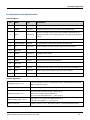
Unit Rating
L1 I
max
L2 I
max
L3 I
max
5 kW - 208 Vac
NA
32 A
32 A
5 kW - 400 Vac
NA
16 A
16 A
10 kW - 208 Vac
56 A
32 A
32 A
10 kW - 400 Vac
28 A
16 A
16 A
15 kW - 208 Vac
56 A
56 A
56 A
15 kW - 400 Vac
28 A
28 A
28 A
Agilent N8900 Series Operating and Service Guide
29
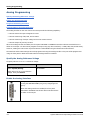
AC Mains Connections
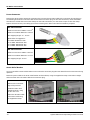
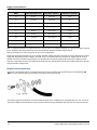
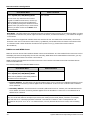
Power Connector
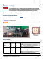
Remove the strain relief to access the connector plug. Connect the AC mains cable to the connector plug as shown in
the following illustrations. Insert the cable wires into the connector plug. On 400 VAC connectors, insert a flat blade
screwdriver to release the internal wire clamp. On 208 VAC connectors, turn the screw to open or close the clamp.
Tighten all wires securely. The safety ground wire must be green. Other colors are for illustration purposes.
400 VAC Connector
Maximum wire size: 8 AWG or 10 mm2
Maximum insulation diameter: 6.8 mm
Wire stripping length: 13 - 15 mm
Optional ferrule suggestion:
For 8 AWG: WAGO 216-289
For 10 AWG: WAGO 216-288
For 12 AWG: WAGO 216-287
For 14 AWG: WAGO 216-286
208 VAC Connector
Maximum wire size: 6 AWG or 16 mm2
Maximum insulation diameter: 8.1 mm
Wire stripping length: 12 mm
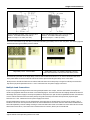
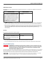
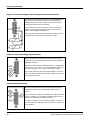
Strain Relief Bracket
You must install the strain relief bracket to ensure that the connector plug does not detach from the instrument during
operation.
Fasten the power cable to the strain relief bracket as shown below, using the supplied tie wraps. This reduces weight
and movement of the AC mains cable at the connector plug.
Make sure the connector
plug is fully inserted.
Install the strain relief
bracket as shown, using
the four hex nuts.
Fasten the AC mains cable
to the strain relief using
the supplied tie wraps.
30
Agilent N8900 Series Operating and Service Guide
Single Unit Connections
Single Unit Connections
Single Load Connections
Multiple Load Connections
Remote Sense Connections
Positive and Negative Voltages
Output Connections
SHOCK HAZARD Turn off AC power before making rear panel connections.
HAZARDOUS VOLTAGES All models generate voltages in excess of 60 VDC, with some
models rated at up to 1,500 VDC! Ensure that all instrument connections, load wiring,
and load connections are either insulated or covered so that no accidental contact
with lethal output voltages can occur.
All output connections must be made with the unit turned off, and must be performed
by qualified personnel who are aware of the hazards involved. Improper actions can
cause fatal injury as well as equipment damage.
Never touch cables or connections immediately after turning off the unit. Depending on the model,
lethal voltages can remain at the output terminals for 10 seconds or more after turn-off. Verify that
there is no dangerous voltage on the output or sense terminals before touching them.
Positive output terminal isolation is up to +1,500 V from ground (varies by model). Negative output
terminal isolation is ±400 V from ground. You cannot ground the positive output terminal of models
rated higher than 400 V.
The following factors should be considered when wiring the load to the power supply:
l
Load wire current carrying capacity
l
Load wire insulation rating (must be equivalent to the maximum output voltage)
l
Load wire voltage drop
l
Load wire noise and impedance effect
Wire Sizes
FIRE HAZARD To satisfy safety requirements, load wires must be large enough not to
overheat when carrying the maximum short circuit current of the power supply. With
more than one load, any pair of load wires must be capable of safely carrying the fullrated current of the supply.
The following table lists the characteristics of AWG (American Wire Gauge) copper wire. Paralleled wires may be substituted for single wires. For example, two AWG 3/0 (95 mm2 ) cables may be paralleled for units rated at 510 A. Paralleled load wires may be required for larger-ampacity power supplies.
Agilent N8900 Series Operating and Service Guide
31
Single Unit Connections
AWG
Nearest Metric size
Ampacity (Note1)
Resistance (Note2)
12
4 mm2
up to 30 A
1.59
10
6 mm2
up to 40 A
1.0
8
10 mm2
up to 60 A
0.63
6
16 mm2
up to 80 A
0.395
2
35 mm2
up to 140 A
0.156
1/0
50 mm2
up to 195 A
0.098
2/0
70 mm2
up to 225 A
0.078
3/0
95 mm2
up to 260 A
0.062
4/0
120 mm2
up to 300 A
0.049
Note 1. Ampacity is based on a single conductor in free air, 26-30 °C ambient temperature, with the conductor rated at
60 °C. Ampacity ratings decrease when wires are bundled an at higher ambient temperatures.
Note 2. Resistance is in ohms/1000 feet, at 20 °C wire temperature.
Along with conductor temperature, you must also consider voltage drop when selecting wire sizes. Although the power
supply will compensate for the voltage in the load wires, it is recommended to minimize the voltage drop as much as
possible to prevent excessive output power consumption from the power supply and poor dynamic response to load
changes. Larger diameter wire sizes will help minimize load-wire voltage drops. Twisting or bundling load wires will help
reduce transient voltage drops.
Single Load Connections
As shown in the following figure, terminate all load wires with the proper wire terminal lugs securely attached. DO
NOT use unterminated wires when making connections at the power supply.
The following figures illustrates the recommended hardware sizes. A hardware kit is shipped with your unit. You must
provide the cables and terminations. Ensure that the cable-mounting hardware does not short the output terminals.
32
Agilent N8900 Series Operating and Service Guide
Single Unit Connections
Use the M8 diameter bolts, nuts, ring lugs, and
washers - for models rated under 500 V.
Maximum torque: 12.4 Nm (9.2 lb-ft).
Use the M6 diameter bolts, nuts, ring lugs, and
washers - for models rated 500 V and up.
Maximum torque: 7.3 Nm (5.4 lb-ft).
Route the load leads through the safety cover before attaching the safety cover to the rear panel. The following figures
illustrate the two types of safety covers installed.
Large safety cover - for all models.
Small safety cover - for models rated 500 V and up.
Units units rated 500 V and up use both safety covers.
Knockouts are provided on the large safety cover so that the load wires can be run in various directions. Note that
heavy load cables must have some form of strain relief to prevent bending the safety cover or bus-bars.
Always twist or bundle the load wires to reduce lead inductance and noise pickup. The goal is to always minimize the
loop area or physical space between the + and - load wires from the power supply to the load.
Multiple Load Connections
If you are using local sensing and are connecting multiple loads to one output, connect each load to the output terminals using separate load wires as shown in the following figure. This minimizes mutual coupling effects and takes full
advantage of the power supply's low output impedance. Keep each wire-pair as short as possible and twist or bundle the
wires to reduce lead inductance and noise pickup. The goal is to always minimize the loop area or physical space
between the + and - load wires from the power supply to the load.
If load considerations require the use of distribution terminals that are located away from the power supply, twist or
bundle the wires from the output terminals to the remote distribution terminals. Connect each load to the distribution
terminals separately. Remote voltage sensing is recommended under these circumstances. Sense either at the remote
distribution terminals or, if one load is more sensitive than the others, directly at the critical load.
Agilent N8900 Series Operating and Service Guide
33
Single Unit Connections
Remote Sense Connections
When the sense leads are not connected to the load, the power supply will internally sense the voltage at the output
terminals (referred to as local sensing), which regulates the output voltage at the output terminals. This does not compensate for the load lead voltage drop.
Remote sensing improves the voltage regulation at the load by monitoring the voltage at the load rather than at the
output terminals. This lets the power supply compensate for the voltage drop in the load leads. Remote sensing is useful for CV operation with load impedances that vary or have significant lead resistance. It has no effect during CC operation. Because sensing is independent of other power supply functions, remote sensing can be used regardless of how
the power supply is programmed.
Equipment Damage Always connect the + sense lead to the + terminal of the load and the sense lead to the - terminal of the load. If a sense lead opens during operation the output may
momentarily overshoot. The two center sense terminals are not used.
Connect the unit for remote sensing by connecting the sense leads as close as possible to the load. The power supply
will automatically detect that the remote sense terminals are being used and will compensate for the load lead voltage
drop.
Do NOT bundle the sense wire-pair together with the load wires; keep the load wires and sense wires separate. Keep
the sense wire-pair as short as possible and twist or bundle it to reduce lead inductance and noise pickup.
Note that the sense leads carry only a few milliamperes of current and can be a much lighter gauge than the load
cables. However, note that any voltage drop in the sense leads can degrade the output voltage regulation. Try to keep
the sense lead resistance less than about 0.5 Ω per lead (this requires 20 AWG/1.0 mm2 or heavier for a 50 foot
length).
34
Agilent N8900 Series Operating and Service Guide
Single Unit Connections
Over-voltage Protection
Remote over-voltage protection (OVP) provides a customer-configurable over-voltage protection. When combined with
remote voltage sensing, this allows for more precise voltage protection directly at the load. The OVP circuit monitors the
voltage at the + and – sense terminals if they are connected to the load, or at the output terminals if the sense terminals are not being used. Refer to Programming Output Protection for further information.
Output Noise
Any noise picked up on the sense leads will appear at the output terminals and may adversely affect CV load regulation.
Twist the sense leads or use a ribbon cable to minimize the pickup of external noise. In extremely noisy environments it
may be necessary to shield the sense leads. Ground the shield at the power supply end only; do not use the shield as
one of the sensing conductors.
Positive and Negative Voltages
Either positive or negative voltages with respect to ground can be obtained from the output by grounding (or "commoning") one of the output terminals. Always use two wires to connect the load to the output regardless of where or
how the system is grounded.
SHOCK HAZARD The negative DC output of any unit cannot be more than ±400 VDC
with respect to earth ground. This means that you cannot ground the positive output
terminal of models rated higher than 400 V.
Equipment Damage Before grounding any output terminal, check to see if the load is already
grounded. Incorrect grounding could result in a short circuit.
Agilent N8900 Series Operating and Service Guide
35
Multiple Unit Connections
Multiple Unit Connections
Parallel Connections
Share Connections
Group Connections
Series Connections
SHOCK HAZARD Turn off AC power before making rear panel connections.
HAZARDOUS VOLTAGES All models generate voltages in excess of 60 VDC, with some
models rated at up to 1,500 VDC! Ensure that all instrument connections, load wiring,
and load connections are either insulated or covered so that no accidental contact
with lethal output voltages can occur.
All output connections must be made with the unit turned off, and must be performed
by qualified personnel who are aware of the hazards involved. Improper actions can
cause fatal injury as well as equipment damage.
Never touch cables or connections immediately after turning off the unit. Depending on the model,
lethal voltages can remain at the output terminals for 10 seconds or more after turn-off. Verify that
there is no dangerous voltage on the output or sense terminals before touching them.
Positive output terminal isolation is up to +1,500 V from ground (varies by model). Negative output
terminal isolation is ±400 V from ground. You cannot ground the positive output terminal of models
rated higher than 400 V.
Parallel Connections
SHOCK HAZARD Using bus bars negates the safety function of the safety covers, as the
exposed portion of the bus bar creates a shock hazard.
Equipment Damage Only connect power supplies that have identical voltage and current ratings
in parallel.
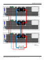
Connecting power supplies in parallel provides a greater current capability than can be obtained from a single unit. The
figure below shows how to connect three units in parallel. If desired, up to 10 units may be connected in parallel.
If remote sensing is desired to compensate for the lead drops, connect the remote sense leads of the unit closest to the
load directly to the load. Although the illustration shows remote sensing being used, it is recommended, but not
required for parallel operation.
Bus bars can be used instead of cables to parallel the output terminals in a stacked configuration. Place the bus bars on
the inside of the output terminals. Keep the wiring from the power supply to the load as short as possible and twist or
bundle the leads to reduce lead inductance and noise pickup. The goal is to always minimize the loop area or physical
space between the + and - output leads from the power supply to the load.
36
Agilent N8900 Series Operating and Service Guide
Multiple Unit Connections
Agilent N8900 Series Operating and Service Guide
37
Multiple Unit Connections
Share Connections
The Share terminals must be connected for parallel operation as shown in the figure above. For further information
about current sharing, refer to Current Share Operation. The following figures details the Share bus connections for
multiple units.
Group Connections
A Group or master/slave configuration can also be used when connecting units in parallel as shown in the figure. This
allows one designated unit to be the master controller of all of the units connected in the group. Grouped connections
use a digital RS485 bus. Connections are made using standard CAT5 or better cables. For further information about
group configurations, refer to Group Operation.
Do not connect an Ethernet port to a Group connector.
The following figure details the termination switch settings for the grouped units. Only the first and last units in the connection chain need to have the switch set to the "terminated" position.
Switches up - unterminated, normal
Group
Connections
Switches down - terminated, only
for units at the beginning and end of
the instrument chain
Series Connections
SHOCK HAZARD Series connections are not allowed as floating voltages must not
exceed the ratings given in the specifications table.
38
Agilent N8900 Series Operating and Service Guide
Analog Port Connections
Analog Port Connections
Analog connections are made through the 15 pin analog connector (Type: Sub-D, D-Sub) on the rear of the unit. Use a
standard connector plug (customer-supplied) to make all connections. Remember to turn of the unit before making
any rear panel connections.
Equipment DamageThe analog interface is galvanically separated from DC output and referenced
to earth ground. Therefore never connect a ground from the analog interface to the +DC or -DC outputs. Use an isolated, ungrounded, programming source to prevent ground loops when using the
analog interface.
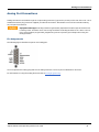
Pin Assignments
The following figure identifies the pins on the analog port.
You must provide the mating plug that for the analog connector. Use a 15-pin D-subminiature connector.
For information on using the analog functions refer to Analog Programming.
Agilent N8900 Series Operating and Service Guide
39
Interface Connections
Interface Connections
GPIB Connections
USB Connections
LAN Connections - site and private
This section describes how to connect to the various communication interfaces on your power supply. For further
information about configuring the remote interfaces, refer to Remote Interface Configuration.
If you have not already done so, install the Agilent IO Libraries Suite, which can be found at www.agilent.com/find/iolib
.
For detailed information about interface connections, refer to the documentation included with the
Agilent IO Libraries Suite.
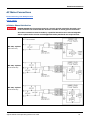
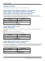
GPIB Connections
The following figure illustrates a typical GPIB interface system.
1. Connect your instrument to the GPIB interface card using a GPIB interface cable.
2. Use the Connection Expert utility of the Agilent IO Libraries Suite to configure the GPIB card’s parameters.
3. You can now use Interactive IO within the Connection Expert to communicate with your instrument, or you can program your instrument using the various programming environments.
USB Connections
The following figure illustrates a typical USB interface system.
1. Connect your instrument to the USB port on your computer.
40
Agilent N8900 Series Operating and Service Guide
Interface Connections
2. With the Connection Expert utility of the Agilent IO Libraries Suite running, the computer will automatically recognize the instrument. This may take several seconds. When the instrument is recognized, your computer will display the
VISA alias, IDN string, and VISA address. This information is located in the USB folder.
3. You can now use Interactive IO within the Connection Expert to communicate with your instrument, or you can program your instrument using the various programming environments.
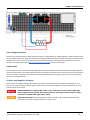
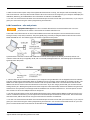
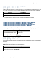
LAN Connections - site and private
Equipment DamageNever insert a network cable which is connected to Ethernet or its components into the master- slave socket on the back side of the unit.
A site LAN is a local area network in which LAN-enabled instruments and computers are connected to the network
through routers, hubs, and/or switches. They are typically large, centrally-managed networks with services such as
DHCP and DNS servers. The following figure illustrates a typical site LAN system.
A private LAN is a network in which LAN-enabled instruments and computers are directly connected, and not connected to a site LAN. They are typically small, with no centrally-managed resources. The following figure illustrates a
typical private LAN system.
1. Connect the instrument to the site LAN or to your computer using a LAN cable. The as-shipped instrument LAN settings are configured to automatically obtain an IP address from the network using a DHCP server (DHCP is set On). The
DHCP server will register the instrument’s hostname with the dynamic DNS server. The hostname as well as the IP
address can then be used to communicate with the instrument. If you are using a private LAN, you can leave all LAN
settings as they are. Most Agilent products and most computers will automatically choose an IP address using auto-IP if
a DHCP server is not present. Each assigns itself an IP address from the block 169.254.nnn. The front panel Lan indicator will come on when the LAN port has been configured.
2. Use the Connection Expert utility of the Agilent IO Libraries Suite to add the Agilent N8900 models and verify a connection. To add the instrument, you can request the Connection Expert to discover the instrument. If the instrument
cannot be found, add the instrument using the instrument’s hostname or IP address.
3. You can now use Interactive IO within the Connection Expert to communicate with your instrument, or you can program your instrument using the various programming environments. You can also use the Web browser on your computer to communicate with the instrument as described under Using the Web Interface.
Agilent N8900 Series Operating and Service Guide
41
Getting Started
Getting Started
Turn the Unit On
Set the Output Voltage
Set the Output Current
Set the Over-Voltage Protection
Enable the Output
Use the Built-in Help System
Turn the Unit On
Verify that the line cord is connected and plugged in to the correct AC line voltage.
Turn the unit on with the front panel power switch. Rotate the knob from 0 to 1. The front panel display will light up
after a few seconds. A power-on self-test occurs automatically when you turn the unit on. This test assures you that
the power supply is operational.
It may take about 30 seconds or so for the power supply to initialize before it is ready for use.
If the instrument does not turn on, verify that the power cord is firmly connected. Also make sure that the instrument
is connected to an energized power source.
If the power-on self test fails, the display shows ERR in the lower right corner. See SCPI Error Messages for information on error codes. See Service and Repair - Introduction for instructions on returning the instrument for service.
Set the Output Voltage
Method 1
Turn the Voltage knob to set the output voltage. The setting value appears in the Set field on the bottom of the display.
42
Agilent N8900 Series Operating and Service Guide
Getting Started
Method 2
Use the left and right navigation keys to navigate to the setting that you wish to change.
In the following display, the voltage setting is selected. Enter a value using the numeric keypad. Then press Select.
You can also use the numeric arrow keys to adjust the value up or down. Values become effective when the output is
enabled.
Method 3
Use the Voltage key to select the voltage entry field. In the display below, the voltage setting is selected. Enter the
desired setting using the numeric keypad. Then press Enter.
If you make a mistake, either use the backspace key to delete the number, press Back to back out of the menu, or
press Meter to return to meter mode.
Set the Output Current
Method 1
Turn the Current knob to set the output current. The setting value appears in the Set field on the bottom of the display.
Agilent N8900 Series Operating and Service Guide
43
Getting Started
Method 2
Use the left and right navigation keys to navigate to the setting that you wish to change.
In the display below, the current setting is selected. Enter a value using the numeric keypad. Then press Select.
You can also use the numeric arrow keys to adjust the value up or down. Values become effective when the output is
turned on.
Method 3
Use the Current key to select the current entry field. In the display below, the current setting is selected. Enter the
desired setting using the numeric keypad. Then press Select.
If you make a mistake, either use the backspace key to delete the number, press Back to back out of the menu, or
press Meter to return to meter mode.
Set the Over-Voltage Protection
Use the front panel menu.
The front panel command menu lets you access most of the power supply’s functions. The actual function controls are
located at the lowest menu level. Briefly:
l
Press the Menu key to access the command menu.
l
Press the left and right (<, >)navigation keys to move across the menu commands.
l
Press the center Select key to select a command and move down to the next level in the menu.
l
Press the Help key at the lowest menu level to display help information about the function controls.
44
Agilent N8900 Series Operating and Service Guide
Getting Started
l
To exit the command menu press the Meter key to immediately return to meter mode, or press the Menu key to
return to the top level.
For a map of the front panel menu commands, refer to Front Panel Menu Reference.
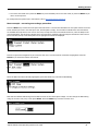
Menu example - accessing over-voltage protection.
Press the Menu key to access the front panel command menu. The first line identifies the menu path. When the menu
is first accessed, the menu is at the top or root, and the path is empty. The second line indicates the commands that
are available at the present menu level. In this case, the top-level menu commands are shown, with the Output command highlighted. The third line indicates which commands are available under the Output command. If there are no
lower level commands, a brief description of the highlighted command is displayed.
Press the right arrow navigation key > to traverse the menu until the Protect command is highlighted. Press the
Select key to access the Protect commands.
Since the OVP command is already highlighted, press the Select key to access the OVP dialog.
Note that the default OVP setting for all models is 120% of the rated ouptut voltage. You can change the OVP setting
using the numeric entry keys. Then press Select. Press the Meter key to return to meter view.
Agilent N8900 Series Operating and Service Guide
45
Getting Started
Enable the Output
HAZARDOUS VOLTAGES All models generate voltages in excess of 60 VDC, with some
models rated at up to 1,500 VDC! Ensure that all instrument connections, load wiring,
and load connections are either insulated or covered so that no accidental contact
with lethal output voltages can occur.
Use the On/Off key to enable the output. If a load is connected to the output, the front panel display will indicate that
it is drawing current. Otherwise, the current reading will be zero. The status indicator shows the output’s status. In this
case, "CV" indicates the output is in constant voltage mode.
If the output current is set to zero, the output voltage may remain as zero when the output is
enabled, and a UNR status may appear in the display. You must program a minimum current value
for the output voltage to rise to its programmed setting.
For a description of the status indicators, refer to Front Panel Display at a Glance.
Use the Built-in Help System
View the list of help topics.
Press the Help key to view the context-sensitive help. Information about the present display is presented.
Press Meter or Back to exit Help.
View the help information for displayed messages.
Whenever a limit is exceeded or any other invalid configuration is found, the instrument will display a message, including Error code information.
Press Meter or Back to exit Help.
46
Agilent N8900 Series Operating and Service Guide
Remote Interface Configuration
Remote Interface Configuration
USB Configuration
GPIB Configuration
LAN Configuration
Modifying the LAN Settings
Using the Web Interface
Using Telnet
Using Sockets
Interface Lockout
Introduction
This instrument supports remote interface communication over three interfaces: GPIB, USB, and LAN. All three interfaces are "live" at power up. To use the interfaces, you must first install the Agilent IO Libraries software, found at
www.agilent.com/find/iolib .
The front panel IO indicator comes on whenever there is activity on the remote interfaces. The front panel Lan indicator comes on when the LAN port is connected and configured.
This instrument provides Ethernet connection monitoring. With Ethernet connection monitoring, the instrument’s
LAN port is continually monitored, and automatically reconfigured when the instrument is unplugged for a minimum of
20 seconds and then reconnected to a network
USB Configuration
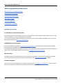
There are no configurable USB parameters. You can retrieve the USB connect string using the front panel menu:
Front Panel Menu
Select System\IO\USB
SCPI Command
Not available
The dialog displays the USB connect string.
GPIB Configuration
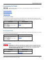
Each device on the GPIB (IEEE-488) interface must have a unique whole number address between 0 and 30. The
instrument ships with the address set to 5. Your computer’s GPIB interface card address must not conflict with any
instrument on the interface bus. This setting is non-volatile; it will not be changed by power cycling or *RST. Use the
front panel menu to change the GPIB address:
Front Panel Menu
Select System\IO\GPIB
SCPI Command
Not available
Use the numeric keys to enter a new value
from 0 to 30. Then press Enter.
Agilent N8900 Series Operating and Service Guide
47
Remote Interface Configuration
LAN Configuration
The following sections describe the primary LAN configuration functions on the front-panel menus. Note that there are
no SCPI commands to configure the LAN parameters. All LAN configuration must be done from the front panel.
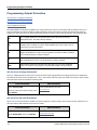
After changing the LAN settings, you must Save the changes. Select: System\IO\LAN\Apply.
Selecting Apply activates the settings. LAN settings are non-volatile, they will not be changed by
power cycling or *RST. If you do not want to save your changes select: System\IO\LAN\Cancel.
Selecting Cancel cancels all changes.
When shipped, DHCP is on, which may enable communication over LAN. The letters DHCP stands for Dynamic Host Configuration Protocol, a protocol for assigning dynamic IP addresses to devices on a network. With dynamic addressing, a
device can have a different IP address every time it connects to the network.
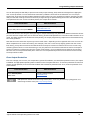
Viewing Active Settings
To view the currently active LAN settings:
Front Panel Menu
Select System\IO\LAN\Settings
SCPI Command
Not available
Displays the active LAN settings. Use the up
and down arrow key to scroll through the list.
The currently active settings for the IP Address, Subnet Mask, and Default Gateway may be different from the front
panel configuration menu settings - depending on the configuration of the network. If the settings are different, it is
because the network has automatically assigned its own settings
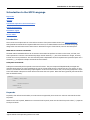
Resetting the LAN
You can perform an LXI LCI reset of the LAN settings. This resets DHCP, DNS server address configuration, mDNS
state, and web password. These settings are optimized for connecting your instrument to a site network. They should
also work well for other network configurations.
You can also reset the LAN to the as-shipped settings. This returns ALL LAN settings to the as-shipped values and
restarts networking. All default LAN settings are listed under Non-volatile Settings.
Front Panel Menu
Select System\IO\LAN\Reset
SCPI Command
Not available
Select System\IO\LAN\Defaults
Select Reset.
Selecting Reset activates the selected LAN settings and restarts networking.
48
Agilent N8900 Series Operating and Service Guide
Remote Interface Configuration
Modifying the LAN Settings
IP Address
Select IP to configure the addressing of the instrument. Press the Menu key, then select System\IO\LAN\Config\IP. The configurable parameters include:
Front Panel Menu
Select System\IO\LAN\Modify\IP
SCPI Command
Not available
Select Auto or Manual. See below for a full
description.
l
Auto - automatically configures the addressing of the instrument. When selected, the instrument will first try to
obtain an IP address from a DHCP server. If a DHCP server is found, the DHCP server will assign an IP address, Subnet Mask, and Default Gateway to the instrument. If a DHCP server is unavailable, the instrument will try to obtain
an IP address using AutoIP. AutoIP automatically assigns an IP address, Subnet Mask, and Default Gateway
addresses on networks that do not have a DHCP server.
l
Manual - allows you to manually configure the addressing of the instrument by entering values in the following
three fields. These fields only appear when Manual is selected.
l
IP Address - This value is the Internet Protocol (IP) address of the instrument. An IP address is required for all IP
and TCP/IP communications with the instrument. An IP Address consists of 4 decimal numbers separated by periods. Each decimal number ranges from 0 through 255 with no leading zeros (for example, 169.254.2.20).
l
Subnet Mask - This value is used to enable the instrument to determine if a client IP address is on the same local
subnet. The same numbering notation applies as for the IP Address. When a client IP address is on a different subnet, all packets must be sent to the Default Gateway.
l
DEF Gateway - This value is the IP Address of the default gateway that allows the instrument to communicate
with systems that are not on the local subnet, as determined by the subnet mask setting. The same numbering
notation applies as for the IP Address. A value of 0.0.0.0 indicates that no default gateway is defined.
Dot-notation addresses ("nnn.nnn.nnn.nnn" where "nnn" is a byte value from 0 to 255) must be expressed with
care, as most PC web software interprets byte values with leading zeros as octal (base 8) numbers. For example,
"192.168.020.011" is actually equivalent to decimal "192.168.16.9" because ".020" is interpreted as "16"
expressed in octal, and ".011" as "9". To avoid confusion, use only decimal values from 0 to 255, with no leading
zeros.
Host Name
A hostname is the host portion of the domain name, which is translated into an IP address. To configure the hostname
of the instrument:
Agilent N8900 Series Operating and Service Guide
49
Remote Interface Configuration
Front Panel Menu
SCPI Command
Select System\IO\LAN\Modify\Name
Not available
You can enter any value from the numeric
keypad. For additional characters, use the up/down navigation keys to enter an alpha character by scrolling through the selection list that
appears when you press the keys. Use the backspace key to delete a value. Press Enter when
you are finished.
Host Name - This field registers the supplied name with the selected naming service. If the field is left blank, no name
is registered. A hostname may contain upper and lower case letters, numbers and dashes (-). The maximum length is
15 characters.
Each instrument is shipped with a default hostname with the format: A-modelnumber-serialnumber, where modelnumber is the unit’s 6-character model number (e.g. N6950A), and serialnumber is the last five characters of the
10-character serial number located on the label on the top of the unit (e.g. 45678 if the serial number is
MY12345678).
DNS Server and WINS Server
DNS is an internet service that translates domain names into IP addresses. It is also needed for the instrument to find
and display its hostname assigned by the network. Normally, DHCP discovers the DNS address information; you only
need to change this if DHCP is unused or not functional.
WINS configures the Windows service of the instrument. This is similar to the DNS service that translates domain
names into IP addresses.
To manually configure the DNS and WINS services:
Front Panel Menu
Select System\IO\LAN\Modify\DNSor
Select System\IO\LAN\Modify\WINS
SCPI Command
Not available
Select Primary Address or Secondary Address.
See below for a full description.
l
Primary Address - This field enters the primary address of the server. Contact your LAN administrator for server
details. The same numbering notation applies as for the IP Address. A value of 0.0.0.0 indicates that no default
server is defined.
l
Secondary Address - This field enters the secondary address of the server. Contact your LAN administrator for
server details. The same numbering notation applies as for the IP Address. A value of 0.0.0.0 indicates that no
default server is defined.
Dot-notation addresses ("nnn.nnn.nnn.nnn" where "nnn" is a byte value from 0 to 255) must be expressed with
care, as most PC web software interprets byte values with leading zeros as octal (base 8) numbers. For example,
"192.168.020.011" is actually equivalent to decimal "192.168.16.9" because ".020" is interpreted as "16"
expressed in octal, and ".011" as "9". To avoid confusion, use only decimal values from 0 to 255, with no leading
zeros.
50
Agilent N8900 Series Operating and Service Guide
Remote Interface Configuration
mDNS Service Name
The mDNS service name is registered with the selected naming service. To configure the mDNS service name of the
instrument:
Front Panel Menu
Select System\IO\LAN\Modify\mDNS
SCPI Command
Not available
You can enter any value from the numeric
keypad. For additional characters, use the
up/down navigation keys to enter an alpha
character by scrolling through the selection
list that appears when you press the keys.
Use the backspace key to delete a value.
Press Enter when you are finished.
l
mDNS Service Name - This field registers the service name with the selected naming service. If the field is left
blank, no name is registered. A service name may contain upper and lower case letters, numbers and dashes(-).
l
Each instrument is shipped with a default service name with the format: Agilent-modelnumber-description-serialnumber, where modelnumber is the unit’s 6-character model number (e.g. N6950A), description is the description, and serialnumber is the 10-character serial number located on the label on the top of the unit (e.g.
MY12345678).
Services
This selects the LAN services to enable or disable.
Front Panel Menu
Select System\IO\LAN\Modify\Services
SCPI Command
Not available
Check or uncheck the services that you wish
to enable or disable.
l
The configurable services include: VXI-11, Telnet, Web control, Sockets, and mDNS.
l
You must enable Web control if you wish to remotely control your instrument using its built-in Web interface.
Using the Web Interface
HAZARDOUS VOLTAGES All models generate voltages in excess of 60 VDC, with some
models rated at up to 1,500 VDC! Ensure that all instrument connections, load wiring,
and load connections are either insulated or covered so that no accidental contact
with lethal output voltages can occur.
Your power supply has a built-in Web interface that lets you control it directly from the Web browser on your computer.
With the Web interface, you can access the front panel control functions including the LAN configuration parameters.
Up to six simultaneous connections are allowed. With multiple connections, performance will be reduced.
The built-in Web interface only operates over the LAN. It requires Internet Explorer 7+. You also
need the Java Plug-in version 7+. This is included in the Java Runtime Environment.
Agilent N8900 Series Operating and Service Guide
51
Remote Interface Configuration
The Web interface is enabled when shipped. To launch the Web interface:
1. Open the Web browser on your computer.
2. Enter the instrument’s hostname or IP address into the browser’s Address field. The following home page will
appear.
3. Click on the Browser Web Control button in the navigation bar on the left to begin controlling your instrument.
4. For additional help about any of the pages, click on the Help with this Page button.
If desired, you can control access to the Web interface using password protection. As shipped, no password is set. To set
a password, click on the View & Modify Configuration button. Refer to the on-line help for additional information about
setting a password.
Using Telnet
In an MS-DOS Command Prompt box type: telnet hostname 5024 where hostname is the instrument's hostname or
IP address, and 5024 is the instrument’s telnet port.
You should get a Telnet session box with a title indicating that you are connected to the power supply. Type the SCPI
commands at the prompt.
52
Agilent N8900 Series Operating and Service Guide
Remote Interface Configuration
Using Sockets
Power supplies allow any combination of up to six simultaneous data socket, control socket, and telnet connections to be made.
Agilent instruments have standardized on using port 5025 for SCPI socket services. A data socket on this port can be
used to send and receive ASCII/SCPI commands, queries, and query responses. All commands must be terminated
with a newline for the message to be parsed. All query responses will also be terminated with a newline.
The socket programming interface also allows a control socket connection. The control socket can be used by a client to
send device clear and to receive service requests. Unlike the data socket, which uses a fixed port number, the port number for a control socket varies and must be obtained by sending the following SCPI query to the data socket:
SYSTem:COMMunicate:TCPip:CONTrol?
After the port number is obtained, a control socket connection can be opened. As with the data socket, all commands to
the control socket must be terminated with a newline, and all query responses returned on the control socket will be
terminated with a newline.
To send a device clear, send the string “DCL” to the control socket. When the power supply has finished performing the
device clear it echoes the string “DCL” back to the control socket.
Service requests are enabled for control sockets using the Service Request Enable register. Once service requests have
been enabled, the client program listens on the control connection. When SRQ goes true the instrument will send the
string “SRQ +nn” to the client. The “nn” is the status byte value, which the client can use to determine the source of
the service request.
Interface Lockout
The USB interface, LAN interface, and the Web server are enabled when shipped. To enable or disable the interfaces
from the front panel:
Front Panel Menu
Select System\Admin\IO
SCPI Command
Not available
Enable or disable the interfaces by checking or
unchecking the following items:
Enable LAN, Enable GPIB, and Enable USB
Then press Select.
If you cannot access the Admin menu, it may be password protected.
Agilent N8900 Series Operating and Service Guide
53
Using the Power Supply
Using the Power Supply
This section contains details on using the instrument, including front panel and remote interface operation. You may
want to read Front-Panel Menu Reference first. See SCPI Programming Reference for details on the SCPI commands to
program the instrument. This section covers:
Programming the Output
Programming Output Protection
Programming Output Steps
Making Measurements
Parallel Operation
Analog Programming
System-Related Operations
Operating Mode Tutorial
54
Agilent N8900 Series Operating and Service Guide
Programming the Output
Programming the Output
When the power supply is first turned on, it may take about 30 seconds or so to initialize the unit
before it is ready for use.
Set the Output Voltage
Set the Output Current
Enable the Output
Set the Output Voltage
You can set the output voltage when the output is either disabled (OFF) or enabled (ON). When enabled, the output
voltage will rise to the programmed setting. This assumes that a minimum output current has been programmed, that
the output has not reached its current limit or power limit boundary.
Front Panel
Turn the Voltage knob while observing the
voltage setting; or
Press the Voltage key, enter a value.
Then press Select.
SCPI Command
To set the output voltage to 90 volts:
VOLT 90
When the unit is operating in constant voltage mode, CV status is displayed on the front panel.
Set the Output Current
You can set the output current when the output is either disabled (OFF) or enabled (ON). When enabled, the output current will be limited at its programmed setting.
Front Panel
Turn the Current knob while observing
the current setting; or
Press the Current key, enter a Value.
Then press Select.
SCPI Command
To set the output current to 100 amps:
CURR 100
When the unit is operating in constant current mode, CC status is displayed on the front panel.
Enable the Output
HAZARDOUS VOLTAGES All models generate voltages in excess of 60 VDC, with some
models rated at up to 1,500 VDC! Ensure that all instrument connections, load wiring,
and load connections are either insulated or covered so that no accidental contact
with lethal output voltages can occur.
Front Panel
Press the On/Off key.
SCPI Command
To turn the output on or off:
OUTP ON|OFF
Agilent N8900 Series Operating and Service Guide
55
Programming Output Protection
Programming Output Protection
Set the Over-Voltage Protection
Set the Over-Current Protection
Clear Output Protection
The Agilent N8900 series power supplies have many protection functions. A front panel status indicator will turn on
when a protection function has been set. Most protection functions are latching, which means that they must be
cleared once they have been set. Of the following protection functions, only the OV and OC are user-programmable.
OV
Over-Voltage protection is a hardware OVP whose trip level is a user-programmable value. The OVP is always enabled.
OC
Over-Current protection is a user-programmable function that can be enabled or
disabled. When enabled, the output will be disabled when the output current
reaches the current limit setting.
OT
Over-Temperature protection monitors the internal temperature of the power
supply and disables the output if the temperature exceeds the factory-defined
limit. The OT protection is always enabled.
PF
Power-Fail indicates that a low voltage condition on the AC mains has occurred
and has disabled the output. The PF protection is always enabled.
MSP
Master/Slave Protection indicates that a fault has occurred in the paralleled
group. The outputs of all grouped units are disabled. MSP is always enabled.
Set the Over-Voltage Protection
The over-voltage protection will turn the output off if the output voltage reaches the programmed over-voltage limit.
The OVP circuit monitors the voltage at the + and – sense terminals if they are connected to the load, or at the output
terminals if the sense terminals are not being used.
Front Panel Menu
Select Protect\OVP
Enter the value in the OVP level box. Then
press Select.
SCPI Command
To set the OVP level to 55 volts:
VOLT:PROT 55
Set the Over-Current Protection
When over-current protection is enabled, the power supply turns off the output if the output current reaches the current limit setting and transitions from CV to CC mode.
Front Panel Menu
Select Protect\OCP
Check Enable OCP. Then press Select.
56
SCPI Command
To enable OCP:
CURR:PROT:STAT ON
Agilent N8900 Series Operating and Service Guide
Programming Output Protection
You can also specify an OCP delay to prevent momentary output settings, load, and status changes from tripping the
over-current protection. In most cases these momentary conditions would not be considered an over-current protection fault, and having an OCP condition disable the output when they occur would be a nuisance. Specifying an OCP
delay lets the OCP circuit ignore these momentary changes during the specified delay period. Once the OCP delay time
has expired and the over-current condition persists, the output will shut down.
Front Panel Menu
Select Protect\OCP
Enter a delay value. Then press Select.
SCPI Command
To specify a 10 millisecond delay:
CURR:PROT:DEL 0.01
Factors that influence how long the settings change or output load change may last include: difference between old output value and new output value, the current limit setting, and the load capacitance in CV mode or load inductance in CC
mode. The delay required must be determined empirically; the output programming-response time characteristics may
be used as guidelines.
Note that the time it takes the output to go into CC mode varies - depending on the magnitude of the over-current condition compared to the current limit setting. For example, if the over-current is only slightly greater than the current
limit setting, it may take several tens of milliseconds for the output to set the CC status bit. If the over-current is significantly greater than the current limit setting, it may only take a few hundred microseconds or less for the output to
set the CC status bit. To determine when the output will shut down, you must add the time it takes for the CC status
bit to the over-current protection delay time. If the over-current persists beyond the sum of these two time intervals,
the output will shut down.
Clear Output Protection
If an over-voltage, over-current, over-temperature, power-fail condition, or master/slave protection occurs, the output
is disabled. The appropriate operating status indicator on the front panel will be on. To clear the protection function and
restore normal operation, first remove that condition that caused the protection fault. Then, clear the protection function as follows:
Front Panel Menu
Select Protect\Clear
Select Clear.
SCPI Command
To clear a protection fault:
OUTP:PROT:CLE
MSP protection cannot be cleared using Protect\Clear. It can only be cleared by cycling power or rediscovering the slave units (see Group Configuration).
Agilent N8900 Series Operating and Service Guide
57
Programming Output Steps
Programming Output Steps
The transient system of the Agilent N8900 HPS lets you generate output steps. An output step is a one-time event
that steps the output voltage or current up or down in response to a trigger. The following steps are required to generate a triggered output step:
l
Enable the output to respond to step triggers
l
Program the voltage or current step levels
l
Initiate the transient system
l
Trigger the output step
Enable the output to respond to step triggers
First, you must enable the output to respond to Step triggers. Unless an output is enabled to respond to triggers, nothing will happen even if you have programmed a trigger level and generated a trigger for the output.
Front Panel Menu
Select Transient\Mode.
For voltage step triggering, set the transient mode to Step. For current step triggering, set the transient mode to Step.
SCPI Command
To enable the transient function to
respond to step triggers, use:
VOLT:MODE STEP
or
CURR:MODE STEP
Then press Select.
In Step mode, the triggered value becomes the immediate value when the trigger is received. In
Fixed mode, trigger signals are ignored; the immediate values remain in effect when a trigger is
received.
Program the voltage or current step levels
Next, use the following commands to program a triggered level. The output will go to this level when the trigger is
received.
Front Panel Menu
Select Transient\Step.
Select the Trig Voltage box to set the
voltage. Select the Trig Current box to set
the current.
SCPI Command
To set a voltage step level to 55 V, and a
current step level to 110 A, use:
VOLT:TRIG 55
CURR:TRIG 110
Enter a value and press Select.
Initiate the transient system
When the unit is turned on, the trigger system is in the idle state. In this state, the trigger system is disabled, ignoring
all triggers. The INITiate commands enable the trigger system to receive triggers.
58
Agilent N8900 Series Operating and Service Guide
Programming Output Steps
Front Panel Menu
Select Transient\Control.
Scroll to Initiate. Then press Select.
SCPI Command
To initiate the transient trigger system:
INIT:TRAN
It takes a few milliseconds for the instrument to be ready to receive a trigger signal after receiving the INITiate:TRANsient command. If a trigger occurs before the trigger system is ready for it, the trigger will be ignored. You can
test the WTG_tran bit in the operation status register to know when the instrument is ready to receive a trigger.
Front Panel Menu
Select Transient\Control.
The Trig state field indicates "Initiated".
SCPI Command
To query the WTG_tran bit (bit 4):
STAT:OPER:COND?
If a bit value of 16 is returned in the query, the WTG_tran bit is true, and the instrument is ready to receive the trigger
signal. Refer to Status Tutorial for more information.
Trigger the output step
The trigger system is waiting for a trigger signal in the initiated state. Trigger the transient as follows:
Front Panel Menu
Select Transient\Control.
Select Trigger to generate an immediate
trigger signal regardless of the trigger
source setting.
SCPI Command
To generate a transient trigger:
TRIG:TRAN
Alternatively, you can also program a
*TRG or an IEEE-488 <get> command.
If the trigger does not occur, you must manually return the trigger system to the idle state. The following commands
return the trigger system to the idle state:
Front Panel Menu
Select Transient\Control.
SCPI Command
ABOR:TRAN
Then select the Abort control.
When a trigger is received, the triggered functions are set to their programmed trigger levels. When the triggered
actions are completed, the trigger system returns to the idle state.
You can test the TRAN_active bit in the Operation Status register to know when the transient trigger system has
returned to the idle state.
Front Panel Menu
Select Transient\Control.
The Trig state field indicates "Idle".
SCPI Command
To query the TRAN_active bit (bit 6):
STAT:OPER:COND?
If a bit value of 64 is returned in the query, the TRAN_active bit is true, and the transient action is NOT complete. When
the TRAN_active bit is false, the transient action is complete. Refer to Status Tutorial for more information.
Agilent N8900 Series Operating and Service Guide
59
Making Measurements
Making Measurements
The Agilent N8900 series has fully integrated voltmeter and ammeter to measure the actual voltage and current that
is being supplied to the load. Whenever the instrument is on, the front panel automatically measures output voltage
and current.
Power measurements are derived from the voltage and current measurements.
Average (DC) Measurements
Use the following commands to make a measurement:
Front Panel
Select the Meter key.
Repeatedly press this key to cycle
through the following measurement
functions:
Voltage, Current
Voltage, Power
Voltage, Current, Power
60
SCPI Command
To measure average (DC) output
voltage, current, or power:
MEAS:VOLT?
MEAS:CURR?
MEAS:POW?
Agilent N8900 Series Operating and Service Guide
Parallel Operation
Parallel Operation
Current Share Operation
Group Operation
Group Configuration
Group Protection
Parallel operation provides the possibility of connecting a number of devices together to create a system with higher
total current and, hence, higher power. Refer to Parallel Connections for detailed information on how to connect the
outputs, share cables, and master/slave cables.
Current Share Operation
The current SHARE cables must be connected on all paralleled units as previously described under Paralleled Connections.
The current share cables allow identical units to share current approximately equally in voltage priority mode. Operation continues until the total current limit of the paralleled group is reached. No additional external connections or programming commands are required.
The following list details the current sharing operation:
l
Program the output voltage of each paralleled unit to the same value.
l
Set the current limit of each paralleled unit so as not to interfere with the expected current sharing level. When
the current limit setting of any paralleled unit is reached, the output current of that unit will limit at its specified
setting. If the current limit of the remaining units is set to a higher value, those units will continue to share current until their current limit is reached.
l
Current sharing continues until the current limit of the group is reached. This allows current to be shared equally
among participating units without any additional external connections or programming considerations.
Group Operation (master/slave)
In addition to the current Share function, which must be used with paralleled units, you can also Group the paralleled
units, with one unit configured as a master controlling up to 9 additional units. Grouping units provides the following
benefits:
l
Program the Output, Transient, Protect, and States functions on only one unit. The programmed settings will automatically be distributed to the connected units.
l
The master unit displays, or makes available to be read by the remote controller, the sum of the actual current values of all the units. The output current of the slave units can be queried individually.
l
The range for setting the values of the master unit is dependent on the number of paralleled units. For example, if
5 units each with a current rating of 90 A are connected to form a 450 A system, then the master can be programmed to provide current in the range from 0 to 450 A.
l
The Group configuration is saved in non-volatile memory.
Agilent N8900 Series Operating and Service Guide
61
Parallel Operation
Group Configuration
To configure the units in a paralleled group:
Configure the Unit as either a Master or Slave
The current SHARE cables must first be connected on all paralleled units as previously described under Paralleled Connections. The units at the end of the grouped connection chain must be terminated by setting the DIP switch located
on the rear panel (see Parallel Connections).
Turn the outputs of all paralleled units off. If the output of any paralleled unit is on, and you try to configure any of the
menu items, a status message will indicate “Output must be off to change configuration".
Front Panel Menu
Select System\Group\Function
SCPI Command
Not available
In the dialog box, select either Master or
Slave. Only select None if the unit is not paralleled. Then press Select.
When a unit has been configured as a slave, the following functions will be disabled, as these will be controlled by the
master unit:
l
Output On/Off.
l
Voltage and Current setting controls.
l
Output, Transient, Protect, and States menu functions.
The SCPI commands that correspond to the above functions are also disabled.
Specify the Address of Each Slave Unit
If the Slave selection is grayed out (unavailable) it means that the unit has not been configured as a slave in the Function menu.
Front Panel Menu
Select System\Group\Slave
SCPI Command
Not available
In the dialog box, select the address of the
slave. Values can range from 1 - 15. Then
press Select.
A maximum of 1 master and up to 9 slaves can be grouped.
View the Configured Slave Unit Addresses
If the Master selection is grayed out (unavailable) it means that the unit has not been configured as a master in the
Function menu.
If the master had previously been configured, a list of slave unit addresses are displayed in the Configured box.
62
Agilent N8900 Series Operating and Service Guide
Parallel Operation
Front Panel Menu
Select System\Group\Master
SCPI Command
Not available
The Configured field displays the addresses of
all connected and configured Slave units.
If the Configured field is blank, press Discover Slaves to discover and display the
addresses of the connected units.
Group Protection
The following protection features are implemented in a grouped configuration:
Power On
At power-on, all grouped units will have their outputs off (unless they have
been configured by the *RCL0 command to be programmed on).
Configuration
check
At power on, the master unit will search for the slave units and compare the list
of slaves found with the previously stored configuration. If the lists match, normal operation continues. If the lists do not match, a Master/Slave Protection
(MSP) fault occurs and the outputs of all units remain off (see Programming
Output Protection). A message is placed in the Error Queue that lists the slave
units found and the slave units expected.
Communications
check
If a master unit loses communication with any slave at any time, it will generate an MSP fault, which turns its own output off as well as the outputs of the
slaves that it can still communicate with. If a slave loses communication with
the master, the slave will also turn its output off.
Agilent N8900 Series Operating and Service Guide
63
Analog Programming
Analog Programming
Specify the Analog Reference Voltage
Enable the Analog Interface
Program the Analog Functions
Pin Descriptions and Characteristics
The analog interface on the rear of the instrument provides the following capability:
l
Remote control of output voltage and current
l
Remote monitoring of OT, OVP, and CV status.
l
Remote monitoring of output voltage and current measurements
l
Remote output off (and on) function
When the analog interface is enabled, the front panel VOLTAGE or CURRENT controls are disconnected and have no
effect on the output. You also cannot program the output using any other interface (i.e. GPIB, LAN, USB, web browser).
However, reading the instrument output and status is still available using the aforementioned interfaces.
The OVP level and the OCP settings cannot be programmed using the analog interface. They can still be programmed
using the front panel or SCPI commands while the analog interface is enabled.
Specify the Analog Reference Voltage
To specify either a 5 V or a 10 V reference voltage:
Front Panel Menu
Select System\Analog.
SCPI Command
Not available
Select either the 5V or 10V reference
voltage. Then press Select.
Enable the Analog Interface
Analog control of the output must be activated by connecting the ANALOG-ENAB input (pin 5) to Digital ground
(pin 4).
When the analog interface is enabled, the front panel
VOLTAGE or CURRENT controls are disconnected and have
no effect on the output.
64
Agilent N8900 Series Operating and Service Guide
Analog Programming
Program the Analog Functions
Equipment Damage The digital and analog ground pins are internally connected to the USB and
GPIB grounds.Only connect these pins to external circuitry that is either at earth ground potential
or, to avoid ground loops, float the connections.
Output Off control
The INHIBIT input (pin 13) can be used in analog control to switch
the output off (and on). It is recommended that a low resistance
contact such as a switch, relay or transistor is used to switch the
pin to digital ground (DGND).
Output current and voltage control using a voltage source
Analog control of the output voltage and current can be
accomplished by connecting positive voltage sources to the
VPROG and IPROG pins as shown.
Depending on the reference voltage selection, a voltage
source variable from 0 to + 5 V or 0 to + 10 V produces an
output current or output voltage setting that is proportional
to the zero to full-scale rating of the power supply.
Note: Using a 0 to 5 V voltage source halves the effective resolution compared to using a 0 to 10 V voltage source.
Agilent N8900 Series Operating and Service Guide
65
Analog Programming
Output current and voltage control using external potentiometers
Analog remote control of the output can be accomplished by
connecting external potentiometers to the VPROG and
IPROG pins as shown. This is similar to the function of the
front panel voltage and current knobs.
The potentiometers must be rated at 10 kΩ. Connect the
VREF pin to one end of the potentiometers. Connect the
wipers to the VPROG and IPROG pins.
Note: Using a 5 V VREF halves the effective resolution of the
potentiometers as compared to using a 10 V VREF.
Output current and voltage measurements
Output current and voltage values can be monitored and
read by connecting a standard multimeter to the VMON and
IMON pins as shown.
Depending on the reference voltage selection, a voltage reading from 0 to + 5 V or 0 to + 10 V corresponds to the zero to
full-scale voltage or current output of the power supply.
The output monitoring pins are always available. You do not
need to enable the analog interface to be able to read the output voltage and current.
Output status monitoring
OT, OVP, and CV status can be monitored by connecting a
standard multimeter to the appropriate status pins as
shown.
For OT and OVP, a reading >4V indicates the status condition
is true. A reading <1V indicates the status is false. For CV, a
reading >4V indicates a CV status condition.
The status monitoring pins are always available. You do not
need to enable the analog interface to be able to monitor the
output status.
66
Agilent N8900 Series Operating and Service Guide
Analog Programming
Pin Descriptions and Characteristics
Pin Descriptions
Pin
Name
Type
Description
1
VPROG
Analog in
Programs output voltage. Only active when A-ENAB is low.
2
IPROG
Analog in
Programs output current. Only active when A-ENAB is low.
3
VREF
Analog out
Reference voltage. Can be connected to VPROG or IPROG directly to
program full scale, or through potentiometers to adjust programmed
values.
4
DGND
Ground
Ground for digital inputs and outputs.
5
ANALOG-ENAB
Digital in
Analog Enable. Enables analog programming when low.
6
OT
Digital out
Over-temperature status indicator. High when OT is tripped.
7, 8
Not used
9
VMON
Analog out
Voltage monitor signal.
10
IMON
Analog out
Current monitor signal.
11
AGND
Ground
Ground for analog inputs and outputs.
12
Not used
13
INHIBIT
Digital in
Inhibits (turns off) output when low. Only active when A-ENAB is low.
14
OVP
Digital out
Over-voltage status indicator. High when OVP is tripped.
15
CV
Digital out
Constant voltage status indicator. High when in CV mode.
Pin Characteristics
Analog Input (pin 1, 2, 8)
Full scale voltage: 5 V or 10 V, depending on Menu:\System\IO\Analog setting.
Input resistance: 150 kΩ.
Analog Output (pin 3, 9, 10)
Full scale voltage: 5 V or 10 V, depending on Menu:\System\IO\Analog setting.
Digital Inputs (pin 5, 13)
Drive with relay to ground or open-collector driver.
Open-circuit voltage: approximately 6.5 V.
Driver current sink requirement: < 0.4 V @ 3 mA
Digital Outputs (pin 6, 14, 15)
High state: 4.74 kΩ pull-up to approximately 10 V.
Low state sink capability: < 0.4 V @ 5 mA
Reference voltage
Voltage: Fixed 5 V or 10 V, depending on Menu:\System\IO\Analog setting.
Agilent N8900 Series Operating and Service Guide
67
System-Related Operations
System-Related Operations
Instrument Identification
Instrument State Storage
Front Panel Display
Password Protection
Instrument Identification
You can query the model number, serial number, options, and firmware revision. SCPI commands let you return information with the *IDN? and *OPT? queries.
Front Panel Menu
Select System\About\Frame.
SCPI Command
To return model number, serial number,
and firmware revision:
*IDN?
To return the installed options:
*OPT?
Instrument State Storage
The power supply has ten storage locations in non-volatile memory to store instrument states. The locations are
numbered 0 through 9. Any state previously stored in the same location will be overwritten.
Front Panel Menu
Select States\SaveRecall.
In the SaveRecall field, enter a location
from 0 to 9. Then press Select.
Select Save to save the state or Recall to
recall a state.
SCPI Command
To save a state in location 1:
*SAV 1
To recall a state from location 1:
*RCL 1
Specifying a power-on state
When shipped from the factory, the power supply is configured to automatically recall the reset (*RST) settings at
power-on. However, you can configure the power supply to recall the settings you have stored in memory location 0
(RCL0) at power-on.
Front Panel Menu
Select States\PowerOn
SCPI Command
OUTP:PON:STAT RCL0
Select Recall State 0. Then press Select.
SHOCK HAZARD If the output is enabled when an instrument state is saved to location
0 (zero), the output will automatically be enabled at turn-on if the power-on state is
set to recall location zero (RCL0).
68
Agilent N8900 Series Operating and Service Guide
System-Related Operations
Front Panel Display
The power supply has a front panel screen saver that significantly increases the life of the LCD display by turning it off
during periods of inactivity. The delay can be set from 30 to 999 minutes in 1 minute increments. As shipped from the
factory, the screen saver comes on one hour after activity on the front panel or interface has ceased.
When the screen saver is active, the front panel display turns off, and the LED next to the Line switch changes from
green to amber. To restore the front panel display, simply press one of the front panel keys. The first action of the key
turns the display on. Subsequently, the key will revert to its normal function.
If the Wake on I/O function is selected, the display is restored whenever there is activity on the remote interface. This
also resets the timer on the screen saver. As shipped, Wake on I/O is active.
Front Panel Menu
Select System\Preferences\Display
SCPI Command
Not available
Enable or disable the screen saver by checking or unchecking the Screen Saver checkbox. Then press Select.
Enter a value in minutes in the Saver Delay
field to specify the time when the screen
saver will activate.
Check Wake on I/O to activate the display
with I/O bus activity.
Password Protection
You can password-protect all functions located in the Admin menu. These include: instrument calibration, interface
access, non-volatile memory reset, firmware update, password updates.
As shipped from the factory, the Admin menu password is 0 (zero). This means that you do not have to enter a password to access the Admin menu. Simply select System\Admin\Login and press Enter. To password-protect the
Admin menu:
Front Panel Menu
Select System\Admin\Password
The password must be numeric, and up to
15 digits long.
Press Select
Log out of the Admin menu to activate the
password. You can now only enter the
Admin menu by providing the right password. Enter the password in the Password
field.
SCPI Command
Enter calibration mode using the original
password
CAL:STAT ON, <password>
To change the password:
CAL:PASS <password>
To exit calibration mode and activate the
password:
CAL:STAT OFF
If the password is lost, access can be restored by setting an internal switch to reset the password to 0. If the message
“Locked out by internal switch setting” or “Calibration is inhibited by switch setting” appears, the internal switch is set
to prevent the password from being changed. Refer to Calibration Switches for more information.
Agilent N8900 Series Operating and Service Guide
69
Operating Mode Tutorial
Operating Mode Tutorial
Voltage Regulation
Current Regulation
Power Regulation
Voltage Regulation
Voltage regulation is also known as constant voltage mode (CV).
In CV mode, the DC output voltage of the power supply is held constant at its voltage setting, unless the output current
or the output power reaches the current limit setting or the power limit. In both cases the device will automatically
change to constant current (CC) or constant power (CP) operation. The output voltage is no longer held constant, and
will sink to a value according to Ohm’s law.
When the power supply is operating in constant voltage mode, the front panel CV status indicator is displayed. The CV
status condition can also be read by the remote interface as well as the analog interface.
The figure below shows an operating locus that is defined by voltage setting, current setting, and power limit of the
unit.The load resistance determines the point on that locus at which the power supply actually operates. The line representing Load resistance A, the highest load resistance shown on the figure, crosses the operating locus at point 1.
Point 1 is on the part of the operating locus defined by the voltage setting, so the power supply operates in CV mode.
70
Agilent N8900 Series Operating and Service Guide
Operating Mode Tutorial
Current Regulation
Current regulation is also known as current limiting or constant current mode (CC).
In CC mode, the DC output current is held constant by the power supply when the output current reaches the current
limit setting. The power supply then switches from CV to CC mode. If, however, the power consumption reaches the
set maximum power value, the device will switch automatically to power limit (CP) where Vout X Iout = Plimit.
When the power supply is operating in constant current mode, the front panel CC status indicator is displayed. The CC
status condition can also be read by the remote interface as well as the analog interface.
In the figure above, the line representing load resistance C, the lowest load resistance shown on the graph, crosses the
operating locus at point 3. Point 3 is on the part of the operating locus defined by the current setting, so the power supply operates in CC mode.
Power Regulation
Power regulation is also known as power limiting or constant power mode (CP).
Constant-Power limit compares the output power against the built-in threshold. A OP protection occurs when the
threshold is exceeded. The OP protection is always enabled.
In CP mode, the DC output power is limited at the unit's maximum rated power. Power limiting operates according to
the auto-ranging principle such that at lower output voltages higher current flows, and at higher output voltages lower
current flows. This maintains the output power within the power rating of the unit supply.
When the power supply is at the constant power limit, the front panel CP status indicator is displayed. The CP status
condition can also be read by the remote interface as well as the analog interface.
The power supply can operate at the power limit without being damaged. However, the power supply is not guaranteed
to meet specifications when operating in power limit mode. Output ripple may increase and neither output voltage or
current is regulated.
In the figure above, the line representing load resistance B crosses the operating locus at point 2. Point 2 is on the output power boundary of the unit, so the power supply operates in CP mode. Press the Meter key to display the power (W)
being supplied to the output.
Refer to Autoranging Characteristic for the power limit indices of the various N8900A models.
Agilent N8900 Series Operating and Service Guide
71
SCPI Programming Reference
SCPI Programming Reference
Introduction to the SCPI Language
Commands by Subsystem
Command Quick Reference
Reset State (*RST)
SCPI Error Messages
Compatibility Commands
Related Information
IO Libraries and Instrument Drivers
The Agilent IO Libraries Suite software is provided on the Agilent Automation Ready CD-ROM provided with your instrument. Installation instructions are provided on the CD-ROM.
You can also download the Agilent IO Libraries Suite software, along with IVI-COM and LabVIEW drivers from the Agilent Developer Network at www.agilent.com/find/adn.
N8900 Series Documentation
You can download this document at www.agilent.com/find/n8900-doc. This document is also provided on a N8900
Product Reference CD-ROM that can be ordered separately.
For detailed information about interface connections, refer to the documentation included with the Agilent IO Libraries
Suite. Or you can download the guide from the Web at www.agilent.com/find/connectivity.
Web Interface
The N8900 series provides a Web interface that is built into the instrument. You can use this interface over LAN for
remote access and control of the instrument via a Web browser. See Using the Web Interface for details.
Example Programs
There are several example programs on the product page Web site at www.agilent.com/find/n8900. These are application-focused programs that demonstrate different programming environments.
72
Agilent N8900 Series Operating and Service Guide
Introduction to the SCPI Language
Introduction to the SCPI Language
Keywords
Queries
Command Separators and Terminators
Syntax Conventions
Parameter Types
Device Clear
Introduction
This instrument complies with the rules and conventions of the present SCPI version (see SYSTem:VERSion?).
SCPI (Standard Commands for Programmable Instruments) is an ASCII-based instrument command language
designed for test and measurement instruments. SCPI has two types of commands, common and subsystem.
IEEE-488.2 Common Commands
The IEEE-488.2 standard defines a set of common commands that perform functions such as reset, self-test, and
status operations. Common commands always begin with an asterisk ( * ), are three characters in length, and may
include one or more parameters. The command keyword is separated from the first parameter by a blank space. Use a
semicolon ( ; ) to separate multiple commands as shown below:
Subsystem Commands
Subsystem commands perform specific instrument functions. They are comprised of alphabetically arranged commands that extend one or more levels below the root in a hierarchical structure, also known as a tree system. In this
structure, associated commands are grouped together under a common node or root, thus forming subsystems. A portion of the OUTPut subsystem is shown below to illustrate the tree system. Note that some [optional] commands have
been included for clarity.
OUTPut
[:STATe] OFF|0|ON|1
:PON
:STATe RST|RCL0
:PROTection
:CLEar
Keywords
Keywords, also referred to as headers, are instructions recognized by the instrument. Common commands are also
keywords.
OUTPut is the root keyword, PROTection is a second-level keyword, CLEar is a third-level keyword. Colons ( : ) separate
the keyword levels.
Agilent N8900 Series Operating and Service Guide
73
Introduction to the SCPI Language
The command syntax shows most commands (and some parameters) as a mixture of upper- and lower-case letters.
The upper-case letters indicate the abbreviated spelling for the command. For shorter program lines, you can send the
abbreviated form. For better program readability, you can send the long form.
In the above examples, OUTP and OUTPUT are both acceptable forms. You can use upper- or lower-case letters. Therefore, OUTPUT, outp, and Outp are all acceptable. Other forms such as OUT, are not valid and will generate an error.
Queries
Following a keyword with a question mark ( ? ) turns it into a query (Example: VOLTage?, VOLTage:TRIGgered?). If a
query contains parameters, place the query indicator at the end of the last keyword, before the parameters. Insert a
space between the query indicator and the first parameter.
You can query the programmed value of most parameters. For example, you can query the voltage setting by sending:
VOLTage?
You can also query the minimum or maximum allowable voltage settings as follows:
VOLTage? MIN
VOLTage? MAX
You must read back all the results of a query before sending another command to the instrument. Otherwise, a Query
Interrupted error will occur and the unreturned data will be lost.
Command Separators and Terminators
Separators
Colons ( : ) separate keyword levels. Blank spaces must be used to separate command parameters from their corresponding keyword. Note the space between STATe and the *RST parameter.
OUTPut:PON:STATe RST
Semicolons ( ; ) separate commands within the same subsystem. This lets you send several subsystem commands
within the same message string. For example, sending the following command string:
OUTPut:STATe ON;PON:STATe RST
is the same as sending the following commands:
OUTPut ON
OUTPut:PON:STATe RST
Note that the semicolon follows the implied path of the hierarchical tree structure. In the above example, the optional
:STATe keyword must follow the OUTput keyword to place the command parser at the second level in the hierarchy.
This allows the use of the PON keyword after the semicolon, since PON is a second-level keyword.
You can also combine commands of different subsystems within the same message string. In this case, you must use a
colon to return the command parser to the root level in order to access another subsystem. For example, you could
clear the output protection and check the status of the Operation Condition register in one message by using a root specifier as follows:
74
Agilent N8900 Series Operating and Service Guide
Introduction to the SCPI Language
OUTPut:PROTection:CLEar;:STATus:OPERation:CONDition?
Note the use of the colon after the semicolon in order to return the command parser to the root.
Terminators
A command string sent to the instrument must terminate with a new line (<NL>) character. The IEEE-488 EOI (EndOr-Identify) message is interpreted as a <NL> character and can be used to terminate a command string in place of an
<NL>. A carriage return followed by a new line (<CR><NL>) is also accepted. Command string termination will always
reset the current SCPI command path to the root level.
Syntax Conventions
l
Triangle brackets ( < > ) indicate that you must specify a value for the enclosed parameter. For example, in the
VOLTage <value> command syntax, the <value> parameter is enclosed in triangle brackets. The brackets are not
sent with the command string. You must specify a value for the parameter (Example: "VOLTage 50V") unless you
select another option shown in the syntax (Example: "VOLTage MAX").
l
A vertical bar ( | ) separates multiple parameter choices for a given command string. For example, RST|RCL0 in the
OUTPut:PON:STATe command indicates that you can specify "RST" or "RCL0". The bar is not sent with the command string.
l
Square brackets ( [ ]) enclose some syntax elements - nodes and parameters for example. This indicates that the
element is optional and can be omitted. The brackets are not sent with the command string. Any keyword
enclosed in brackets is optional and can be omitted. However, if you are combining several commands within the
same message string as previously described, you must include the optional commands to place the command
parser at the correct level in the hierarchy.
Parameter Types
The SCPI language defines several data formats to be used in commands and queries.
Numeric Parameters
Commands that require numeric parameters will accept all commonly used decimal representations of numbers including optional signs, decimal points, and scientific notation. If a command accepts only certain specific values, the instrument will automatically round the input numeric parameters to the accepted values. The following command requires a
numeric parameter for the voltage value:
[SOURce:]VOLTage 50V|MIN|MAX
Note that special values for numeric parameters such as MINimum and MAXimum are also accepted. Instead of selecting a specific value for the voltage parameter, you can substitute MIN to set the voltage to its minimum allowable
value, MAX to set it to its maximum allowable value.
You can also send engineering unit suffixes with numeric parameters (e.g., V for volts, A for amperes, W for Watts). All
parameters values are in base units.
Discrete Parameters
Discrete parameters are used to program settings that have a limited number of values (like IMMediate, EXTernal, or
BUS). They may have a short form and a long form just like command keywords. You can use upper- or lower-case let-
Agilent N8900 Series Operating and Service Guide
75
Introduction to the SCPI Language
ters. Query responses will always return the short form in all upper-case letters. The following command requires a discrete parameter for the display settings:
VOLTage:MODE FIXed|STEP
Boolean Parameters
Boolean parameters represent a single binary condition that is either true or false. For a false condition, the instrument
will accept "OFF" or "0". For a true condition, the instrument will accept "ON" or "1". When you query a Boolean setting, the instrument will always return "0" or "1". The following command requires a Boolean parameter:
OUTput OFF|0|ON|1
ASCII String Parameters
String parameters can contain virtually any set of ASCII characters. A string must begin and end with matching
quotes; either with a single quote or a double quote. You can include the quote delimiter as part of the string by typing
it twice without any characters in between. The following command uses a string parameter:
CALibrate:DATE "12/12/12"
Device Clear
Device Clear is an IEEE-488 low-level bus message that you can use to return the instrument to a responsive state. Different programming languages and IEEE-488 interface cards provide access to this capability through their own unique
commands. The status registers, the error queue, and all configuration states are left unchanged when a Device Clear
message is received.
Device Clear performs the following actions:
l
If a measurement is in progress, it is aborted.
l
The instrument returns to the trigger idle state.
l
The instrument's input and output buffers are cleared.
l
The instrument is prepared to accept a new command string.
The ABORt command is the recommended method to terminate an instrument operation.
76
Agilent N8900 Series Operating and Service Guide
Commands by Subsystem
Commands by Subsystem
Subsystem
CALibrate
DISPlay
MEASure
OUTPut
[SOURce:]
CURRent
VOLTage
STATus
SYSTem
TRIGger
Additional Commands
Compatibility
Agilent N8900 Series Operating and Service Guide
77
Calibrate Commands
Calibrate Commands
Calibrate commands calibrate the instrument.
Read the calibration section before calibrating. Improper calibration can reduce accuracy and reliability.
CALibrate:COUNt?
Returns the number of times the unit has been calibrated. The count is incremented whenever the calibration (including the date) is saved, the administration password is changed, the administration password is reset using the internal
cal switch, or the instrument firmware is updated.
Parameter
(none)
Typical Return
The calibration count
Return the calibration count: CAL:COUN?
CALibrate:CURRent[:LEVel] [<value>]
Calibrates the current programming and measurement. The optional value parameter selects the range to calibrate.
This is for compatibility with the N6700 series modular power system.
Parameter
Optional - the maximum value of the
range.
Typical Return
(none)
Calibrates the current of the 100 A range: CAL:CURR 100
CALibrate:DATA <value>
Enters the calibration value read by the external meter. You must first select a calibration level for the value being
entered. Data values are expressed in base units - either volts or amperes, depending on which function is being calibrated.
Parameter
Numeric value
Typical Return
(none)
Specify calibration value 0.0237: CAL:DATA 2.37E-2
CALibrate:DATE <"date">
CALibrate:DATE?
Enters the calibration date in nonvolatile memory. Enter any ASCII string up to 10 characters. The query returns the
date.
78
Agilent N8900 Series Operating and Service Guide
Calibrate Commands
Parameter
Typical Return
<"date">String program data. Enclose string
parameters in single or double quotes.
Date of last calibration
Enters the calibration date: CAL:DATE "12/12/12"
CALibrate:LEVel P1|P2|P3|P4
CALibrate:LEVel?
Advances to the next level in the calibration. P1 is the first level; P2 the second, P3 the third, and P4 the fourth.
Parameter
P1|P2|P3|P4
Typical Return
(none)
Selects the first calibration point: CAL:LEV P1
l
Some calibration sequences may require some settling time after sending CAL:LEV but before reading the data
from the DVM and sending CAL:DATA.
CALibrate:PASSword <password>
Sets a numeric password to prevent unauthorized calibration.
Parameter
Typical Return
<password>a numeric value up to 15 digits
(none)
Set a new password to a value of 1234: CAL:PASS 1234
l
If the password is set to 0, password protection is removed and the ability to enter calibration mode is unrestricted.
The factory setting is 0 (zero).
l
To change the password: unsecure calibration memory with old code, then set the new code.
l
If you forget your password, refer to the calibration section.
l
This setting is non-volatile; it will not be changed by power cycling or *RST.
CALibrate:SAVE
Saves the calibration constants in non-volatile memory. Do this at the end of the calibration to avoid losing changes.
Parameter
(none)
Typical Return
(none)
Store cal constants in non-volatile memory: CAL:SAVE
Agilent N8900 Series Operating and Service Guide
79
Calibrate Commands
CALibrate:STATe 0|OFF|1|ON [,<password>]
CALibrate:STATe?
Enables or disables calibration mode. Calibration mode must be enabled for the instrument to accept any calibration
commands. The first parameter specifies the state. The second optional parameter is the password.
Parameter
Typical Return
0|OFF|1|ON , default OFF
0 or 1
<password> a numeric value up to 15 digits
(none)
Disable calibration mode and unsecure calibration: CAL:STAT OFF,0
Enable calibration: CAL:STAT ON
<password> is optional to secure the instrument, but must be correct if provided.
CALibrate:VOLTage[:LOCal][:LEVel] [<value>]
Calibrates the local voltage programming and measurement. The optional value parameter selects the range to calibrate. This is for compatibility with the N6700 series modular power system.
Parameter
Optional - the maximum value of the
range.
Typical Return
(none)
Calibrates the voltage of the 80 V range: CAL:VOLT 80
CALibrate:VOLTage:REMote[:LEVel] [<value>]
Calibrates the remote voltage programming and measurement. The optional value parameter selects the range to calibrate. This is for compatibility with the N6700 series modular power system.
Parameter
Optional - the maximum value of the
range.
Typical Return
(none)
Calibrates the voltage of the 80 V range: CAL:VOLT:REM 80
80
Agilent N8900 Series Operating and Service Guide
DISPlay/LXI Commands
DISPlay/LXI Commands
DISPlay[:WINDow][:STATe] 0|OFF|1|ON
DISPlay[:WINDow][:STATe]?
Turns the front panel display on or off.
Parameter
0|OFF|1|ON, *RST ON
Typical Return
0 or 1
Turns the front panel display off: DISP OFF
LXI:IDENtify[:STATe] 0|OFF|1|ON
LXI:IDENtify[:STATe]?
Turns the front panel LXI identify indicator on or off. When turned on, the "LAN" status indicator on the front panel
blinks on and off to identify the instrument that is being addressed.
Parameter
0|OFF|1|ON, *RST OFF
Typical Return
0 or 1
To blink the front panel LXI indicator: LXI:IDENT ON
Agilent N8900 Series Operating and Service Guide
81
MEASure Commands
MEASure Commands
Measure commands measure the output voltage, current, or power. They trigger the acquisition of new data before
returning the reading.
MEASure[:SCALar]:CURRent[:DC]?
MEASure[:SCALar]:POWer[:DC]?
MEASure[:SCALar]:VOLTage[:DC]?
Initiates and triggers a measurement. Returns the averaged output measurement. Values returned are either in
amperes, volts, or watts.
Parameter
(none)
Typical Return
<DC value>
Returns the averaged current MEAS:CURR?
Returns the averaged power MEAS:POW?
Returns the averaged voltage MEAS:VOLT?
82
Agilent N8900 Series Operating and Service Guide
OUTPut Commands
OUTPut Commands
Output commands control the output, power-on, and protection clear functions.
OUTPut[:STATe] 0|OFF|1|ON
OUTPut[:STATe]?
Enables or disables the output. The state of a disabled output is a condition of zero output voltage and zero current.
Parameter
0|OFF|1|ON , *RST OFF
Typical Return
0 or 1
Turns the output off: OUTP OFF
l
When the output is enabled, the instrument status changes from OFF to the operating status (CV, CC, etc.).
HAZARDOUS VOLTAGES All models generate voltages in excess of 60 VDC, with some
models rated at up to 1,500 VDC! Ensure that all instrument connections, load wiring,
and load connections are either insulated or covered so that no accidental contact
with lethal output voltages can occur.
OUTPut:PON:STATe RST|RCL0
OUTPut:PON:STATe?
Sets the output power-on state. This determines whether the power-on state is set to the *RST state (RST) or the
state stored in memory location 0 (RCL0). Instrument states can be stored using the *SAV command. This parameter
is saved in non-volatile memory.
Parameter
RST|RCL0
Typical Return
RST or RCL0
Sets the power-on state to the *RST state: OUTP:PON:STAT RST
SHOCK HAZARD If the output is enabled when an instrument state is saved to location
0 (zero), the output will automatically be enabled at turn-on if the power-on state is
set to recall location zero (RCL0).
OUTPut:PROTection:CLEar
Resets the latched protection. This clears the latched protection status that disables the output when a protection condition occurs (see Programming Output Protection).
Parameter
(none)
Typical Return
(none)
Clears the latched protection status: OUTP:PROT:CLE
l
All conditions that generate the fault must be removed before the latched status can be cleared. The output is
restored to the state it was in before the fault condition occurred.
Agilent N8900 Series Operating and Service Guide
83
[SOURce] Commands
[SOURce] Commands
The SOURce keyword is optional in the following CURRent and VOLTage commands
[SOURce:]CURRent[:LEVel][:IMMediate][:AMPLitude] <value>|MIN|MAX
[SOURce:]CURRent[:LEVel][:IMMediate][:AMPLitude]? [MIN|MAX]
[SOURce:]CURRent[:LEVel]:TRIGgered[:AMPLitude] <value>|MIN|MAX
[SOURce:]CURRent[:LEVel]:TRIGgered[:AMPLitude]? [MIN|MAX]
Sets the immediate current level and the triggered current level when the output is operating in constant current
mode. The triggered level is a stored value that is transferred to the output when an output Step is triggered. Units are
in amperes. The maximum value depends on the current rating of the unit.
Parameter
0 to 102% of rating|MIN|MAX, *RST 0
Typical Return
<current level>
Sets the output current level to 3 A: CURR 3
Sets the triggered current level to 2 A: CURR:TRIG 2
[SOURce:]CURRent:MODE FIXed|STEP
[SOURce:]CURRent:MODE?
Sets the transient mode. This determines what happens to the output current when the transient system is initiated
and triggered.
FIXed keeps the output current at its immediate value.
STEP steps the output to the triggered level when a trigger occurs.
Parameter
FIXed|STEP, *RST FIXed
Typical Return
FIX or STEP
Sets the current mode to Step: CURR:MODE STEP
[SOURce:]CURRent:PROTection:DELay <value>|MIN|MAX
[SOURce:]CURRent:PROTection:DELay? [MIN|MAX]
Sets the over-current protection delay. The over-current protection function will not be triggered during the delay time.
After the delay time has expired, the over-current protection function will be active. This prevents momentary changes
in output status from triggering the over-current protection function. Values up to 65.535 milliseconds can be programmed, with a resolution of 1 millisecond.
Parameter
0 to 65.535, *RST 0.050 s
Typical Return
<delay value>
Sets the protection delay to 0.2 seconds: CURR:PROT:DEL 0.2
84
Agilent N8900 Series Operating and Service Guide
[SOURce] Commands
[SOURce:]CURRent:PROTection:STATe 0|OFF|1|ON
[SOURce:]CURRent:PROTection:STATe?
Enables or disables the over-current protection. If the over-current protection function is enabled and the output goes
into constant current operation, the output is disabled and the Questionable Condition status register OCP bit is set.
Parameter
0|OFF|1|ON, *RST OFF
Typical Return
0 or 1
Enable the current protection state: CURR:PROT:STAT ON
l
The current limit setting determines when the output goes into constant current operation.
l
An over-current condition can be cleared with OUTPut:PROTection:CLEar after the cause of the condition is
removed.
[SOURce:]VOLTage[:LEVel][:IMMediate][:AMPLitude] <value>|MIN|MAX
[SOURce:]VOLTage[:LEVel][:IMMediate][:AMPLitude]? [MIN|MAX]
[SOURce:]VOLTage[:LEVel]:TRIGgered[:AMPLitude] <value>|MIN|MAX
[SOURce:]VOLTage[:LEVel]:TRIGgered[:AMPLitude]? [MIN|MAX]
Sets the immediate voltage level and the triggered voltage level when the output is operating in constant voltage
mode. The triggered level is a stored value that is transferred to the output when an output Step is triggered. Units are
in volts. The maximum value depends on the voltage rating of the unit.
Parameter
0 to 102% of rating|MIN|MAX, *RST 0
Typical Return
<voltage level>
Sets the output voltage level to 20 V: VOLT 20
Sets the triggered voltage level to 25 V: VOLT:TRIG 25
[SOURce:]VOLTage:MODE FIXed|STEP
[SOURce:]VOLTage:MODE?
Sets the transient mode. This determines what happens to the output voltage when the transient system is initiated
and triggered.
FIXed keeps the output voltage at its immediate value.
STEP steps the output to the triggered level when a trigger occurs.
Parameter
FIXed|STEP, *RST FIXed
Typical Return
FIX or STEP
Sets the voltage mode to Step: VOLT:MODE STEP
Agilent N8900 Series Operating and Service Guide
85
[SOURce] Commands
[SOURce:]VOLTage:PROTection[:LEVel] <value>|MIN|MAX
[SOURce:]VOLTage:PROTection[:LEVel]? [MIN|MAX]
Sets the over-voltage protection level. Units are in volts. If the output voltage exceeds the OVP level, the output is disabled and the Questionable Condition status register OV bit is set.
Parameter
0 – 120% of voltage rating|MIN|MAX,
*RST 120% of rating
Typical Return
<over-voltage level>
Sets the over-voltage protection to 60 V: VOLT:PROT 60
l
An over-voltage condition can be cleared with the OUTput:PROTection:CLEar command after the cause of the condition has been removed.
86
Agilent N8900 Series Operating and Service Guide
STATus Commands
STATus Commands
Status commands let you determine the operating condition of the instrument at any time. The instrument has three
groups of status registers; Operation, Questionable, and Standard Event. The Operation and Questionable status
groups each consist of the Condition, Enable, and Event registers as well as NTR and PTR filters.
Instrument status is also programmed using the Common commands: *CLS, *ESE, *ESR?, *OPC, *OPC?, *SRE,
*STB? and *WAI discussed at the end of this topic. Common commands control additional status functions such as the
Service Request Enable and the Status Byte registers. Refer to Status Tutorial for more information.
STATus:OPERation[:EVENt]?
Queries the event register for the Operation Status group. This is a read-only register, which stores (latches) all events
that are passed by the Operation NTR and PTR filter. Reading the Operation Status Event register clears it.
Parameter
(none)
Typical Return
<bit value>
Read the operation status event register: STAT:OPER?
l
*RST has no effect on this register.
l
The value returned is the binary-weighted sum of all bits set in the register.
STATus:OPERation:CONDition?
Queries the condition register for the Operation Status group. This is a read-only register, which holds the live
(unlatched) operational status of the instrument. Reading the Operation Status Condition register does not clear it.
Parameter
(none)
Typical Return
<bit value>
Read the operation status condition register: STAT:OPER:COND?
l
The condition register bits reflect the current condition. If a condition goes away, the corresponding bit is cleared.
l
The value returned is the binary-weighted sum of all bits set in the register.
STATus:OPERation:ENABle <value>
STATus:OPERation:ENABle?
Sets and queries bits in the enable register for the Operation Status group. The enable register is a mask for enabling
specific bits from the Operation Event register to set the OPER (operation summary) bit of the Status Byte register.
STATus:PRESet clears all bits in the enable register.
Parameter
A decimal value that corresponds to the binaryweighted sum of the bits in the register.
Typical Return
<bit value>
Enable bit 3 and 4 in the enable register: STAT:OPER:ENAB 24
Agilent N8900 Series Operating and Service Guide
87
STATus Commands
l
*CLS does not clear the enable register, but does clear the event register.
STATus:OPERation:NTRansition <value>
STATus:OPERation:NTRansition?
STATus:OPERation:PTRansition <value>
STATus:OPERation:PTRansition?
Sets and queries the value of the NTR (Negative-Transition) and PTR (Positive-Transition) registers. These registers
serve as a polarity filter between the Operation Condition and Operation Event registers.
When a bit in the NTR register is set to 1, then a 1-to-0 transition of the corresponding bit in the Operation Condition
register causes that bit in the Operation Event register to be set.
When a bit in the PTR register is set to 1, then a 0-to-1 transition of the corresponding bit in the Operation Condition
register causes that bit in the Operation Event register to be set.
STATus:PRESet sets all bits in the PTR registers and clears all bits in the NTR registers.
Parameter
Typical Return
A decimal value that corresponds to the binaryweighted sum of the bits in the register.
<bit value>
Enable bit 3 and 4 in the NTR register: STAT:OPER:NTR 24
Enable bit 3 and 4 in the PTR register: STAT:OPER:PTR 24
l
If the same bits in both NTR and PTR registers are set to 1, then any transition of that bit at the Operation Condition register sets the corresponding bit in the Operation Event register.
l
If the same bits in both NTR and PTR registers are set to 0, then no transition of that bit at the Operation Condition
register can set the corresponding bit in the Operation Event register .
l
The value returned is the binary-weighted sum of all bits set in the register.
STATus:PRESet
Presets all Enable, PTR, and NTR registers.
Operation register
Questionable register
Preset setting
STAT:OPER:ENAB
STAT:QUES:ENAB
all defined bits are disabled
STAT:OPER:NTR
STAT:QUES:NTR
all defined bits are disabled
STAT:OPER:PTR
STAT:QUES:PTR
all defined bits are enabled
Parameter
(none)
Typical Return
(none)
Preset the Operation and Questionable registers: STAT:PRES
88
Agilent N8900 Series Operating and Service Guide
STATus Commands
STATus:QUEStionable[:EVENt]?
Queries the event register for the Questionable Status group. This is a read-only register, which stores (latches) all
events that are passed by the Operation NTR and PTR filter. Reading the Questionable Status Event register clears it.
Parameter
(none)
Typical Return
<bit value>
Read questionable status event register: STAT:QUES?
l
*RST has no effect on this register.
l
The value returned is the binary-weighted sum of all bits set in the register.
STATus:QUEStionable:CONDition?
Queries the condition register for the Questionable Status group. This is a read-only register, which holds the live
(unlatched) operational status of the instrument. Reading the Questionable Status Condition register does not clear it.
Parameter
(none)
Typical Return
<bit value>
Read questionable status condition register: STAT:QUES:COND?
l
The condition register bits reflect the current condition. If a condition goes away, the corresponding bit is cleared.
l
*RST clears this register, other than those bits where the condition still exists after *RST.
l
The value returned is the binary-weighted sum of all bits set in the register.
STATus:QUEStionable:ENABle <value>
STATus:QUEStionable:ENABle?
Sets and queries bits in the enable register for the Questionable Status group. The enable register is a mask for
enabling specific bits from the Operation Event register to set the QUES (questionable summary) bit of the Status Byte
register. STATus:PRESet clears all bits in the enable register.
Parameter
A decimal value that corresponds to the binaryweighted sum of the bits in the register.
Typical Return
<bit value>
Enable bit 2 and 4 in the questionable enable register: STAT:QUES:ENAB 24
l
*CLS does not clear the enable register, but does clear the event register.
Agilent N8900 Series Operating and Service Guide
89
STATus Commands
STATus:QUEStionable:NTRansition <value>
STATus:QUEStionable:NTRansition?
STATus:QUEStionable:PTRansition <value>
STATus:QUEStionable:PTRansition?
Sets and queries the value of the NTR (Negative-Transition) and PTR (Positive-Transition) registers. These registers
serve as a polarity filter between the Questionable Condition and Questionable Event registers.
When a bit in the NTR register is set to 1, then a 1-to-0 transition of the corresponding bit in the Questionable Condition register causes that bit in the Questionable Event register to be set.
When a bit in the PTR register is set to 1, then a 0-to-1 transition of the corresponding bit in the Questionable Condition
register causes that bit in the Questionable Event register to be set.
STATus:PRESet sets all bits in the PTR registers and clears all bits in the NTR registers.
Parameter
Typical Return
A decimal value that corresponds to the binaryweighted sum of the bits in the register.
<bit value>
Enable bit 3 and 4 in the questionable NTR register: STAT:QUES:NTR 24
Enable bit 3 and 4 in the questionable PTR register: STAT:QUES:PTR 24
l
If the same bits in both NTR and PTR registers are set to 1, then any transition of that bit at the Questionable Condition register sets the corresponding bit in the Questionable Event register.
l
If the same bits in both NTR and PTR registers are set to 0, then no transition of that bit at the Questionable Condition register can set the corresponding bit in the Questionable Event register .
l
The value returned is the binary-weighted sum of all bits set in the register.
*CLS
Clear Status Command. Clears the event registers in all register groups. Also clears the Status Byte and Error Queue. If
*CLS immediately follows a program message terminator (<NL>), then the Output Queue and the MAV bit are also
cleared. Refer to Status Tutorial for more information.
Parameter
(none)
Typical Return
(none)
Clear Event register bits, Status byte, and Error queue: *CLS
*ESE <value>
*ESE?
Event Status Enable Command and Query. Enables bits in the enable register for the Standard Event Status group. A 1
in the bit position enables the corresponding event. The selected bits are then reported to the ESB bit of the Status
Byte Register. The query reads the enable register and returns a decimal value which corresponds to the binaryweighted sum of all bits set in the register. Refer to Status Tutorial for more information.
90
Agilent N8900 Series Operating and Service Guide
STATus Commands
Parameter
Typical Return
A decimal value that corresponds to the binaryweighted sum of the bits in the register.
<bit value>
Enable bit 3 and 4 in the enable register: *ESE 24
l
Any or all conditions can be reported to the ESB bit through the enable register. To set the enable register mask,
write a decimal value to the register using *ESE.
l
*CLS does not clear the enable register, but does clear the event register.
l
The value returned is the binary-weighted sum of all bits set in the register.
*ESR?
Event Status Event Query. Queries the event register for the Standard Event Status group. The event register is a
read-only register, which stores (latches) all standard events. Refer to Status Tutorial for more information.
Parameter
(none)
Typical Return
<bit value>
Read event status enable register: *ESR?
l
Any or all conditions can be reported to the ESB bit through the enable register. To set the enable register mask,
write a decimal value to the register using *ESE.
l
Once a bit is set, it remains set until cleared by this query or *CLS.
l
The value returned is the binary-weighted sum of all bits set in the register.
*OPC
Sets the OPC (operation complete) bit in the Standard Event register. This occurs at the completion of the current operation. Refer to Status Tutorial for more information.
Parameter
(none)
Typical Return
(none)
Set the Operation Complete bit: *OPC
l
The purpose of this command is to synchronize your application with the instrument.
l
Used in conjunction with initiated acquisitions, initiated transients, output state changes, and output to settling
time to provide a way to poll or interrupt the computer when these pending operations complete.
l
Other commands may be executed before the operation complete bit is set.
l
The difference between *OPC and *OPC? is that *OPC? returns "1" to the output buffer when the current operation completes.
Agilent N8900 Series Operating and Service Guide
91
STATus Commands
*OPC?
Returns a 1 to the output buffer when all pending operations complete. The response is delayed until all pending operations complete.
Parameter
(none)
Typical Return
1
Return a 1 when commands complete: *OPC?
l
The purpose of this command is to synchronize your application with the instrument.
l
Other commands cannot be executed until this command completes.
*SRE <value>
*SRE?
Service Request Enable Command and Query. Sets the value of the Service Request Enable register. This determines
which bits from the Status Byte Register are summed to set the Master Status Summary (MSS) bit and the Request for
Service (RQS) summary bit. A 1 in any Service Request Enable register bit position enables the corresponding Status
Byte register bit. All such enabled bits are then logically OR-ed to cause the MSS bit of the Status Byte register to be set.
Refer to Status Tutorial for more information.
The query reads the enable register and returns a decimal value which corresponds to the binary-weighted sum of all
bits set in the register.
Parameter
Typical Return
A decimal value that corresponds to the binaryweighted sum of the bits in the register.
<bit value>
Enable bit 3 and 4 in the enable register: *SRE 24
l
When a serial poll is conducted in response to SRQ, the RQS bit is cleared, but the MSS bit is not.
l
When *SRE is cleared (by programming it with 0), the power supply cannot generate an SRQ to the controller.
*STB?
Status Byte Query. Reads the Status Byte Register, which contains the status summary bits and the Output Queue
MAV bit. The Status Byte is a read-only register and the bits are not cleared when it is read. Refer to Status Tutorial for
more information.
Parameter
(none)
Typical Return
<bit value>
Read status byte: *STB?
92
Agilent N8900 Series Operating and Service Guide
STATus Commands
*WAI
Pauses additional command processing until all pending operations are complete. See OPC for more information.
Parameter
(none)
Typical Return
(none)
Wait until all pending operations complete.*WAI
l
*WAI can only be aborted by sending the instrument a Device Clear command.
Agilent N8900 Series Operating and Service Guide
93
SYSTem Commands
SYSTem Commands
System commands control system functions that are not directly related to output control, measurement, or status
functions.
System functions are also controlled using the Common commands: *IDN?, *LRN?, *OPT?, *RCL, *RST, *SAV, and
*TST? discussed at the end of this topic.
SYSTem:COMMunicate:LAN:CONTrol?
SYSTem:COMMunicate:TCPip:CONTrol?
Returns the initial socket control connection port number. This connection is used to send and receive commands and
queries. Unlike the data socket, which uses a fixed port number, the control socket port number varies and must be
obtained using these queries.
Parameter
(none)
Typical Return
5000 (0 if sockets are not supported)
Query the Control connection port number:
SYST:COMM:LAN:CONT? or SYST:COMM:TCP:CONT?
SYSTem:COMMunicate:RLSTate LOCal|REMote|RWLock
SYSTem :COMMunicate:RLSTate?
Configures the remote/local state of the instrument. Remote and Local do the same thing and are included for compatibility with other products. Both allow front panel control.
RWLock disables the front panel keys. Then the instrument can only be controlled via the remote interface.
Parameter
LOCal|REMote|RWLock, default LOCal
Typical Return
LOC, REM, or RWL
Sets the remote/local state to remote: SYST:COMM:RLST REM
l
The remote/local state is unaffected by *RST or any SCPI commands other than SYSTem:COMMunicate:RLState.
l
The remote/local instrument state can also be set by other interface commands over the GPIB and some other I/O
interface.
SYSTem:ERRor?
Reads and clears one error from the error queue.
Parameter
(none)
Typical Return
<+0,"No error">
Reads and clear first error in error queue: SYST:ERR?
94
Agilent N8900 Series Operating and Service Guide
SYSTem Commands
l
The front-panel ERR annunciator turns on when one or more errors are currently stored in the error queue. Error
retrieval is first-in-first-out (FIFO), and errors are cleared as you read them. When you have read all errors from
the error queue, the ERR annunciator turns off.
l
If more than 20 errors have occurred, the last error stored in the queue (the most recent error) is replaced with 350,"Error queue overflow". No additional errors are stored until you remove errors from the queue. If no errors
have occurred when you read the error queue, the instrument responds with +0,"No error".
l
The error queue is cleared by the *CLS and when power is cycled. It is not cleared by a *RST.
l
Errors have the following format (the error string may contain up to 255 characters).
<error code>,<error string>
For a list of error codes and message strings, see SCPI Error Messages.
SYSTem:SECurity:IMMediate
Clears all user memory and reboots the instrument. This command is typically used to prepare the instrument for
removal from a secure area. It writes all zeros to flash memory and then performs a full chip erase as per the manufacturer’s data sheet. Identification data such as instrument firmware, model number, serial number, MAC address,
and calibration data is not erased. After the data is cleared, the instrument is rebooted.
This procedure is not recommended for use in routine applications because of the possibility of unintended loss of data.
Parameter
Typical Return
(none)
(none)
Sanitizes the instrument: SYST:SEC:IMM
SYSTem:VERSion?
Returns the SCPI version that the instrument complies with. Cannot be determined from front panel.
Parameter
Typical Return
(none)
<"version">
Return the SCPI version: SYST:VERS?
l
The command returns a string in the form "YYYY.V", where YYYY represents the year of the version and V represents a version for that year.
*IDN?
Identification Query. Returns instrument’s identification string, which contains four comma-separated fields. The first
field is the manufacturer's name, the second field is the instrument model number, the third field is the serial number,
and the fourth field is the firmware revision.
Parameter
(none)
Typical Return
Agilent Technologies,N8925A,MY00123456,A.01.01
Return the instrument's identification string: *IDN?
Agilent N8900 Series Operating and Service Guide
95
SYSTem Commands
*LRN?
Returns a sequence of SCPI commands that can later be used to put the instrument in the same state that it was in
when the *LRN? query was sent. The scope of the returned settings is the same as for the *SAV and *RCL commands.
Parameter
(none)
Typical Return
ASCII string with semicolon-separated fields
Returns the sequence of SCPI commands: *LRN?
l
To read the string into your computer, be sure to dimension a string variable with at least 2500 characters.
*OPT?
Returns a string identifying any installed options. A 0 (zero) indicates no options are installed.
Parameter
(none)
Typical Return
OPT 760
Returns installed options: *OPT?
*RCL <0-9>
Restores the instrument to a state that was previously stored in memory locations 0 through 9 with the *SAV command. All instrument states are recalled except: (1) the trigger system is set to the Idle state, (2) calibration is disabled, (3) trigger settings are set to their Idle state, and (4) non-volatile settings are not affected..
Parameter
0 -9
Typical Return
(none)
Recall state from location 1: *RCL 1
l
Location 0 is automatically recalled at power turn-on when the Output Power-On state is set to RCL0.
l
You cannot recall an instrument state from an empty or deleted storage location.
l
Stored instrument states are affected by *RST.
SHOCK HAZARD If the output is enabled when an instrument state is saved to location
0 (zero), the output will automatically be enabled at turn-on if the power-on state is
set to recall location zero (RCL0).
*RST
Resets the instrument to pre-defined values that are either typical or safe. These settings are described in Factory
Reset State.
96
Agilent N8900 Series Operating and Service Guide
SYSTem Commands
Parameter
(none)
Typical Return
(none)
Reset the instrument: *RST
l
*RST forces the ABORt command. This cancels any trigger actions presently in process, and resets the WTG bit in
the Status Operation Condition register.
*SAV <0-9>
Saves the present state of the instrument to one of ten non-volatile memory locations.
Parameter
0 -9
Typical Return
(none)
Save state to location 1: *SAV 1
l
If a particular state is desired at power-on, it should be stored in location 0. Location 0 is automatically recalled at
power turn-on when the Output Power-On state is set to RCL 0.
l
The calibration state is NOT saved as part of the *SAV operation.
l
Data saved in non-volatile memory, described in the Non-volatile Settings, is not affected by the *SAV command.
l
When shipped, locations 0 through 9 are empty.
*TST?
Self-Test Query. Performs a instrument self-test. If test fails, one or more error messages will provide additional information. Use SYSTem:ERRor? to read error queue. See SCPI Error Messages for more information.
Parameter
(none)
Typical Return
Always returns 0
Perform self-test: *TST?
l
The power-on self-test is the same self-test performed by *TST.
l
*TST? also forces an *RST command.
Agilent N8900 Series Operating and Service Guide
97
Trigger Commands
Trigger Commands
Trigger commands control the remote triggering of the instrument's output. Abort commands abort any pending triggers. Initiate commands initiate the transient trigger system.
ABORt:TRANsient
Cancels any triggered actions. It returns the trigger system back to the Idle state and resets the WTG-tran bit in the
Operation Condition Status register.
Parameter
Typical Return
(none)
(none)
Aborts the triggered action: ABOR:TRAN
l
Note that this command does not turn off continuous triggers if INITiate:CONTinuous:TRANsient ON has been programmed. In this case, the trigger system will automatically re-initiate.
l
ABORt:TRANsient is also executed at power-on and upon execution of the *RST command.
INITiate[:IMMediate]:TRANsient
Initiates the transient trigger system. This moves the trigger system from the "idle" state to the "wait-for-trigger"
state; which enables the instrument to receive triggers.
Parameter
Typical Return
(none)
(none)
Initiates the trigger system: INIT:TRAN
l
It takes a few milliseconds for the instrument to be ready to receive a trigger signal after receiving the INITiate
command.
l
If a trigger occurs before the trigger system is ready for it, the trigger will be ignored. Check the WTG_tran bit in
the operation status register to know when the instrument is ready.
l
Use ABORt:TRANsient to return the instrument to idle.
INITiate:CONTinuous:TRANsient 0|OFF|1|ON
INITiate:CONTinuous:TRANsient?
Continuously initiates the transient trigger system. This allows multiple triggers to generate multiple output transients.
Parameter
0|OFF|1|ON , *RST ON
Typical Return
0 or 1
Continually initiates the trigger system: INIT:CONT:TRAN ON
98
Agilent N8900 Series Operating and Service Guide
Trigger Commands
l
With continuous triggering disabled, the trigger system must be initiated for each trigger using the INITiate:TRANsient command.
l
ABORt:TRANsient does not abort continuous triggers if INITiate:CONTinuous:TRANsient ON has been programmed. In this case, the trigger system will automatically re-initiate.
TRIGger:TRANsient[:IMMediate]
Generates an immediate trigger. This overrides any selected trigger source. Transient triggers affect the output
voltage and output current.
Parameter
(none)
Typical Return
(none)
Generates a transient trigger: TRIG:TRAN
l
You must initiate the trigger system before you can send any trigger.
l
When sent, the transient trigger will cause an output change as specified by the CURRent:TRIGgered or
VOLTage:TRIGgered commands.
l
When the trigger sequence completes, the WTG-tran bit in the Status Operation Condition register is cleared.
TRIGger:TRANsient:SOURce <source>
TRIGger:TRANsient:SOURce?
Selects the transient trigger source. BUS is the only trigger source that can be selected. This selects a remote trigger
interface command as the trigger source.
Parameter
BUS
Typical Return
BUS
Example: TRIG:TRAN:SOUR BUS
*TRG
Trigger Command. Generates a trigger when the trigger system has BUS selected as its source. The command has the
same affect as the Group Execute Trigger (<GET>) command).
Parameter
(none)
Typical Return
(none)
Generates an immediate trigger: *TRG
Agilent N8900 Series Operating and Service Guide
99
Status Tutorial
Status Tutorial
This section provides a detailed description of the individual registers and register groups. The status diagram at the end
of this topic provides an graphical view of how the status registers and groups are interconnected.
Status Registers
Operation Status Group
Questionable Status Group
Standard Event Status Group
Status Byte Register
Error and Output Queues
Status Diagram
Status Registers
The Operation and Questionable status groups use four different type of registers to track qualify, flag, and enable
instrument events.
l
A Condition register continuously monitors the state of the instrument. The bits in the condition register are
updated in real time and the bits are not latched or buffered
l
An PTR/NTR register qualifies the signal that passes to the event register. When a PTR bit is set, signals with positive edge transition pass to the event register. When an NTR bit is set, signals with a negative edge transition pass
to the event register. When both bits are set, all signal pass. When neither bits are set, no signals pass.
l
An Event register latches the various events from the condition register. There is no buffering in this register;
while an event bit is set, subsequent events corresponding to that bit are ignored. This is a read-only register
l
An Enable register defines which bits in the event register will be reported to the Status Byte register group. You
can write to or read from an enable register.
To program individual bits in any register group, you must send a value that corresponds to the binary-weighted value
of all the bits that you wish to enable. For example, to enable bit 2 (decimal value = 4) and bit 4 (decimal value = 16),
the corresponding decimal value would be 20 (4 + 16).Similarly, any register queries return the binary-weighted value
of the bits that have been set. For example, with bit 3 (value 8) and bit 5 (value 32) being set, the query returns +40.
Operation Status Group
These registers record signals that occur during normal operation. The group consists of a Condition, PTR/NTR, Event,
and Enable register. The outputs of the Operation Status register group are logically-ORed into the OPERation summary bit (7) of the Status Byte register. Refer to Status Registers for a description of each register.
The following table describes the Operation Status register bit assignments.
100
Agilent N8900 Series Operating and Service Guide
Status Tutorial
Bit
Decimal
Value
Bit Name
Definition
0
CV
1
Output is in constant voltage
1
CC
2
Output is in constant current
2
OFF
4
Output is programmed off
3
not used
not used
0 is returned
4
WTG-tran
16
Transient system is waiting or a trigger
5-15
not used
not used
0 is returned
Questionable Status Group
These register groups record signals that indicate abnormal operation. The group consists of a Condition, PTR/NTR,
Event, and Enable register. The outputs of the Questionable Status group are logically-ORed into the QUEStionable
summary bit (3) of the Status Byte register. Refer to Status Registers for a description of each register.
The following table describes the Questionable Status register bit assignments.
Bit
Bit Name
Decimal
Value
Definition
0
OV
1
Output is disabled by the over-voltage protection
1
OC
2
Output is disabled by the over-current protection
2
PF
4
Output is disabled by power-fail (low-line or brownout on AC
line)
3
CP
8
Output is limited by the power limit boundary
4
OT
16
Output is disabled by the over-temperature protection
5
MSP
32
Output is disabled by the master/slave protection
not used
not used
0 is returned
9
INH
512
Output is disabled by an external INHibit signal
10
UNR
1024
Output is unregulated
not used
not used
0 is returned
6-8
11-15
Standard Event Status Group
These registers are programmed by Common commands. The group consists of an Event and Enable register.The
Standard Event event register latches events relating to communication status. It is a read-only register that is
Agilent N8900 Series Operating and Service Guide
101
Status Tutorial
cleared when read. The Standard Event enable register functions similarly to the enable registers of the Operation and
Questionable status groups. Refer to Status Registers for a description of each register.
The following table describes the Standard Event Status register bit assignments.
Bit
Bit Name
Decimal
Value
Definition
0
Operation
Complete
1
All commands before and including *OPC have been executed.
1
not used
not used
0 is returned
2
Query Error
4
The instrument tried to read the output buffer but it was empty,
a new command line was received before a previous query has
been read, or both the input and output buffers are full.
3
Device-Specific
Error
8
A device-specific error, including a self-test error, calibration
error or other device-specific error occurred. Error Messages
4
Execution
Error
16
An execution error occurred. Error Messages
5
Command
32
A command syntax error occurred. Error Messages
6
not used
not used
0 is returned
7
Power On
128
Power has been cycled since the last time the event register was
read or cleared.
Status Byte Register
This register summarizes the information from all other status groups as defined in the IEEE 488.2 Standard Digital
Interface for Programmable Instrumentation.
The following table describes the Status Byte Register register bit assignments.
Bit
102
Bit Name
Decimal
Value
Definition
0
not used
not used
0 is returned
1
not used
not used
0 is returned
2
Error Queue
4
One or more errors in the Error Queue. Use SYSTem:ERRor?
to read and delete errors.
3
Questionable
Status Summary
8
One or more bits are set in the Questionable Data Register.
Bits must be enabled, see STATus:QUEStionable:ENABle.
4
Message
Available
16
Data is available in the instrument's output buffer.
Agilent N8900 Series Operating and Service Guide
Status Tutorial
Bit
Bit Name
Decimal
Value
Definition
5
Event Status
Summary
32
One or more bits are set in the Standard Event Register. Bits
must be enabled, see *ESE.
6
Master Status
Summary
64
One or more bits are set in the Status Byte Register and may
generate a Service Request. Bits must be enabled, see *SRE.
7
Operation Status
Summary
128
One or more bits are set in the Operation Status Register. Bits
must be enabled, see STATus:OPERation:ENABle.
MSS and RQS Bits
MSS is a real-time (unlatched) summary of all Status Byte register bits that are enabled by the Service Request Enable
register. MSS is set whenever the instrument has one or more reasons for requesting service. *STB? reads the MSS in
bit position 6 of the response but does not clear any of the bits in the Status Byte register.
The RQS bit is a latched version of the MSS bit. Whenever the instrument requests service, it sets the SRQ interrupt
line true and latches RQS into bit 6 of the Status Byte register. When the controller does a serial poll, RQS is cleared
inside the register and returned in bit position 6 of the response. The remaining bits of the Status Byte register are not
disturbed.
Error and Output Queues
The Error Queue is a first-in, first-out (FIFO) data register that stores numerical and textual description of an error or
event. Error messages are stored until they are read with SYSTem:ERRor? If the queue overflows, the last error/event
in the queue is replaced with error -350,"Queue overflow".
The Output Queue is a first-in, first-out (FIFO) data register that stores instrument-to-controller messages until the
controller reads them. Whenever the queue holds messages, it sets the MAV bit (4) of the Status Byte register.
Agilent N8900 Series Operating and Service Guide
103
Status Tutorial
Status Diagram
104
Agilent N8900 Series Operating and Service Guide
Command Quick Reference
Command Quick Reference
Some [optional] commands have been included for clarity. All settings commands have a corresponding query. See the
Syntax Conventions for SCPI.
ABORT Command
ABORt
:TRANsient
Cancels any triggered actions.
CALibrate Commands
CALibrate
:COUNt?
Returns the number of times the unit has been calibrated.
:CURRent
[:LEVel] [<value>]
Calibrates the current programming and measurement.
:DATA <value>
Enters the calibration value read by the external meter.
:DATE <"date">
Enters the calibration date in nonvolatile memory.
:LEVel P1|P2|P3|P4
Advances to the next level in the calibration.
:PASSword <value>
Sets a numeric password to prevent unauthorized calibration.
:SAVE
Saves the calibration constants in non-volatile memory.
:STATe 0|OFF|1|ON
Enables or disables calibration mode.
:VOLTage
[:LOCal]
[:LEVel] [<value>]
Calibrates the local voltage programming and measurement.
:REMote
[:LEVel] [<value>]
Calibrates the remote voltage programming and measurement.
DISPlay Command
DISPlay
[:WINDow]
[:STATe] 0|OFF|1|ON
Turns the front panel display on or off.
IEEE-488 Commands
*CLS
Clear status
*ESE <value>
Standard event status enable
*ESR?
Return event status register
*IDN?
Return instrument identification
*LRN?
Returns a sequence of SCPI commands
*OPC
Enable "operation complete" bit in ESR
*OPT?
Return option number
Agilent N8900 Series Operating and Service Guide
105
Command Quick Reference
*RCL <value>
Recalls a saved instrument state
*RST
Reset
*SAV <value>
Saves an instrument state
*SRE <value>
Set service request enable register
*STB?
Return status byte
*TRG
Trigger
*TST?
Performs self-test, then returns result
*WAI
Pauses additional command processing until all device commands are done
INITiate Commands
INITiate
[:IMMediate]
:TRANsient
Initiates the transient trigger system.
:CONTinuous
:TRANsient 0|OFF|1|ON
Continuously initiates the transient trigger system.
LXI Command
LXI
:IDENtify
:STATe 0|OFF|1|ON
Turns the front panel LXI identify indicator on or off.
MEASure Commands
MEASure
[:SCALar]
:CURRent
[:DC]?
Takes a measurement; returns the averaged current.
:POWer
[:DC]?
Takes a measurement; returns the averaged power.
:VOLTage
[:DC]?
Takes a measurement; returns the averaged voltage.
OUTPut Commands
OUTPut
[:STATe] 0|OFF|1|ON
Enables or disables the output.
:PON
:STATe RST|RCL0
Sets the output power-on state.
:PROTection
:CLEar
106
Resets the latched protection.
Agilent N8900 Series Operating and Service Guide
Command Quick Reference
[SOURce:] Commands
[SOURce:]
CURRent
[:LEVel]
[:IMMediate]
[:AMPLitude] <value>
Sets the output current
:TRIGgered
[:AMPLitude] <value>
:MODE FIXed|STEP
Sets the triggered output current
Sets the transient mode.
:PROTection
:DELay <value>
Sets the over-current protection delay.
:STATe 0|OFF|1|ON
Enables or disables the over-current protection.
VOLTage
[:LEVel]
[:IMMediate]
[:AMPLitude] <value>
Sets the output voltage
:TRIGgerred
[:AMPLitude] <value>
:MODE FIXed|STEP
Sets the triggered output voltage
Sets the transient mode.
:PROTection
[:LEVel] <value>
Sets the over-voltage protection level.
STATus Commands
STATus
:OPERation
[:EVENt]?
Queries the operation event register.
:CONDition?
Queries the operation condition register.
:ENABle <value>
Sets the operation enable register.
:NTRansiton <value>
Sets the negative transition filter.
:PTRansiton <value>
Sets the positive transition filter.
:PRESet
Presets all Enable, PTR, and NTR registers.
:QUEStionable
[:EVENt]?
Queries the questionable event register.
:CONDition?
Queries the questionable condition register.
:ENABle <value>
Sets the questionable enable register.
:NTRansiton <value>
Sets the negative transition filter.
:PTRansiton <value>
Sets the positive transition filter.
Agilent N8900 Series Operating and Service Guide
107
Command Quick Reference
SYSTem Commands
SYSTem
:COMMunicate
:LAN|TCPip:CONTrol?
:RLSTate
LOCal|REMote|RWLock
:ERRor?
Returns the initial socket control connection port number.
Configures the remote/local state of the instrument.
Reads and clears one error from the error queue.
:SECurity
:IMMediate
:VERSion?
Clears all user memory and reboots the instrument.
Returns the SCPI version that the instrument complies with.
TRIGger Commands
TRIGger
:TRANsient
108
[:IMMediate]
Generates an immediate trigger.
:SOURce <source>
Selects the transient trigger source.
Agilent N8900 Series Operating and Service Guide
Reset State (*RST)
Reset State (*RST)
The power-on/reset state may differ from that shown below if you have enabled power-on state
recall mode from the States menu (see Instrument State Storage).
The following tables show the reset state. These parameters are reset to the indicated values at power-on or after
*RST.
Reset Settings
SCPI Command *RST Settings
CALibrate:STATe
OFF
CURRent
0
CURRent:MODE
FIXed
CURRent:PROTection:DELay
50 ms
CURRent:PROTection:STATe
OFF
CURRent:TRIGgered
0
DISPlay
ON
OUTPut
OFF
TRIGger:TRANsient:SOURce
BUS
VOLTage
0
VOLTage:MODE
FIXed
VOLTage:PROTection
120% of rating
VOLTage:TRIGgered
0
The following table shows the as-shipped settings of the non-volatile parameters. These are not affected by power cycling or *RST.
Non-Volatile Settings
SCPI as-shipped settings
CALibrate:DATE
empty string
CALibrate:PASSword
0
OUTPut:PON:STATe
RST
Front Panel as-shipped settings
Firmware update password protected
Disabled
Agilent N8900 Series Operating and Service Guide
109
Reset State (*RST)
GPIB address
5
GPIB interface
Enabled
LAN interface
Enabled
USB interface
Enabled
Screen saver
Enabled
Screen saver delay
60 minutes
Wake on I/O
Enabled
Interface as-shipped settings
Get IP Address
Automatic
IP Address
169.254.89.00
Subnet mask
255.255.0.0
Default gateway
0.0.0.0
Host name
A-N89xxx-xxxxx
mDNS service name
A-N89xxx-xxxxx.local.
LAN service - VXI-11
Enabled
LAN service - Telnet
Enabled
LAN service - mDNS
Enabled
LAN service - Web server
Enabled
LAN service - sockets
Enabled
Web password
Blank
110
Agilent N8900 Series Operating and Service Guide
SCPI Error Messages
SCPI Error Messages
The Agilent instrument returns error messages in accord with the SCPI standard.
l
Up to 20 errors can be stored in each interface-specific error queue (one each for GPIB, USB, VXI-11, and Telnet/Sockets.) Errors appear in the error queue of the I/O session that caused the error.
l
The instrument beeps once each time a command syntax or hardware error is generated. The front-panel ERROR
annunciator turns on when one or more errors are in the error queue.
l
A special global error queue holds all power-on and hardware-related errors (for example, over-temperature).
l
Error retrieval is first-in-first-out (FIFO), and errors are cleared as you read them. Once you have read all interfacespecific errors, the errors in the global error queue are retrieved. When you have read all errors from the error
queue, the ERR annunciator turns off.
l
If more than 20 errors have occurred, the last error stored in the queue (the most recent error) is replaced with 350,"Error queue overflow". No additional errors are stored until you remove errors from the queue. If no errors
have occurred when you read the error queue, the instrument responds with +0,"No error".
l
The front panel reports errors from all I/O sessions and the global error queue. To read the error queue from the
front panel, press the ERROR key.
l
Error conditions are also summarized in the Status Byte Register. See Status Subsystem Introduction for details
l
The interface-specific error queues are cleared by power cycles and *CLS. The error queue is not cleared by *RST.
l
SCPI:
SYSTem:ERRor?
Read and clear one error from the queue
Errors have the following format (the error string may contain up to 255 characters):
-113,"Undefined header"
Error Device-dependent Errors (these errors set Standard Event Status register bit #3)
0 No error
This is the response to the ERR? query when there are no errors.
101 Calibration state is off
Calibration is not enabled. The instrument will not accept calibration commands.
102 Calibration password is incorrect
The calibration password is incorrect.
103 Calibration is inhibited by switch setting
Calibration mode is locked out by the calibration switch.
104 Bad sequence of calibration commands
Calibration commands have not been entered in the proper sequence.
116 Locked out by internal switch setting
This function has been locked out by an internal switch.
200 Hardware error channel <1>
A hardware error has occurred on the output.
Agilent N8900 Series Operating and Service Guide
111
SCPI Error Messages
202 Selftest Fail
A selftest failure has occurred. See selftest failure list for details.
209 Internal communication error
An internal communication error has occurred in the instrument.
210 Frame NVRAM error
A non-volatile RAM error has occurred in the instrument.
308 This setting cannot be changed while transient trigger is initiated
Setting cannot be changed while the instrument is waiting for or executing a trigger sequence.
309 Cannot initiate, voltage and current in fixed mode
Cannot initiate transient generator. Either the voltage or current function is set to Fixed mode.
315 Settings conflict error
A data element could not be programmed because of the present instrument state.
317 Invalid format
The saved state file is corrupted.
318 Configuration error
A master/slave configuration error has occurred.
320 Firmware update error
This may be due to the instrument hardware not being able to support the firmware version.
Command Errors (these errors set Standard Event Status register bit #5)
-100 Command error
Generic syntax error.
-101 Invalid character
An invalid character was found in the command string.
-102 Syntax error
Invalid syntax was found in the command string. Check for blank spaces.
-103 Invalid separator
An invalid separator was found in the command string. Check for proper use of , ; :
-104 Data type error
A different data type than the one allowed was found in the command string.
-105 GET not allowed
A group execute trigger is not allowed in a command string.
-108 Parameter not allowed
More parameters were received than were expected.
112
Agilent N8900 Series Operating and Service Guide
SCPI Error Messages
-109 Missing parameter
Fewer parameters were received than were expected.
-110 Command header error
An error was detected in the header.
-111 Header separator error
A character that was not a valid header separator was found in the command string.
-112 Program mnemonic too long
The header contains more than 12 characters.
-113 Undefined header
A command was received that was not valid for this instrument.
-114 Header suffix out of range
The value of the numeric suffix is not valid.
-120 Numeric data error
Generic numeric data error.
-121 Invalid character in number
An invalid character for the data type was found in the command string.
-123 Exponent too large
The magnitude of the exponent was larger than 32000.
-124 Too many digits
The mantissa of a numeric parameter contained more than 255 digits, excluding leading zeros.
-128 Numeric data not allowed
A numeric parameter was received but a character string was expected.
-130 Suffix error
Generic suffix error
-131 Invalid suffix
A suffix was incorrectly specified for a numeric parameter.
-134 Suffix too long
The suffix contains more than 12 characters.
-138 Suffix not allowed
A suffix is not supported for this command.
-140 Character data error
Generic character data error
-141 Invalid character data
Either the character data element contains an invalid character, or the element is not valid.
Agilent N8900 Series Operating and Service Guide
113
SCPI Error Messages
-144 Character data too long
The character data element contains more than 12 characters.
-148 Character data not allowed
A discrete parameter was received, but a string or numeric parameter was expected.
-150 String data error
Generic string data error
-151 Invalid string data
An invalid character string was received. Check that the string is enclosed in quotation marks.
-158 String data not allowed
A character string was received, but is not allowed for this command.
Execution Errors (these errors set Standard Event Status register bit #4)
-200 Execution error
Generic syntax error
-220 Parameter error
A data element related error occurred.
-221 Settings conflict
A data element could not be executed because of the present instrument state.
-222 Data out of range
A data element could not be executed because the value was outside the valid range.
-223 Too much data
A data element was received that contains more data than the instrument can handle.
-224 Illegal parameter value
An exact value was expected but not received.
-225 Out of memory
The device has insufficient memory to perform the requested operation.
-230 Data corrupt or stale
Possible invalid data. A new reading was started but not completed.
-231 Data questionable
The measurement accuracy is suspect.
-232 Invalid format
The data format or structure is inappropriate.
-233 Invalid version
The version of the data format is incorrect to the instrument.
114
Agilent N8900 Series Operating and Service Guide
SCPI Error Messages
-240 Hardware error
The command could not be executed because of a hardware problem with the instrument.
-241 Hardware missing
The command could not be executed because of missing hardware, such as an option.
Query Errors (these errors set Standard Event Status register bit #2)
-400 Query Error
Generic error query
-410 Query INTERRUPTED
A condition causing an interrupted query error occurred.
-420 Query UNTERMINATED
A condition causing an unterminated query error occurred.
-430 Query DEADLOCKED
A condition causing a deadlocked query error occurred.
-440 Query UNTERMINATED after indefinite response
A query was received in the same program message after a query indicating an indefinite response was executed.
Agilent N8900 Series Operating and Service Guide
115
Compatibility Commands
Compatibility Commands
The commands described in this section are provided for compatibility with the existing N6700 series modular power
system (MPS). Note that the compatibility commands discussed in this section have no or little effect on the operation
of the N8900 models, as they access functions that are either redundant or not available.
Channel Parameter
Since the N8900 models are single channel units, SCPI commands do not require a channel list parameter. However,
for code compatibility with the N6700 MPS, the N8900 models will accepts the channel list (, @1) for N6700 MPS commands that require this parameter. All channel-dependent commands sent to the N8900 models must be sent to channel 1 only.
Code Compatible Commands
These commands are not required for the N8900 models, but are provided for better compatibility with code written for
the Agilent N6700 MPS. In most cases these commands either do nothing, or specify a pre-defined parameter that is
compatible with the N8900 models.
N6700 MPS command
Action on N8900 models
SENSe:CURRent:RANGe
Sets and gets the sense current range.
Returns the measurement current range.
[SOURce:]CURRent:RANGe
Sets and gets the source current range.
Returns the output current range.
SENSe:VOLTage:RANGe
Sets and gets the sense voltage range.
Returns the measurement voltage range.
[SOURce:]VOLTage:RANGe
Sets and gets the source voltage range.
Returns the output voltage range.
SYSTem:CHANnel[:COUNt]?
Returns the number of output channels.
Always returns a "1".
SYSTem:CHANnel:MODel?
Returns the channel model number.
Returns the power supply model. Same as *IDN?
SYSTem:CHANnel:OPTion?
Returns the channel options.
Returns the power supply options. Same as *OPT?
SYSTem:CHANnel:SERial?
Returns the channel serial number.
Returns the power supply serial number. Same as *IDN?
SYSTem:GROUp:CATalog?
Returns the number of grouped channels.
Returns a list of discovered slave addresses.
116
Agilent N8900 Series Operating and Service Guide
Service and Maintenance
Service and Maintenance
Further service and maintenance topics:
Verification and Calibration
Self-Test Procedure
Firmware Update
Instrument Sanitize
Calibration Switches
Disassembly
Manual Updates
Types of Service Available
If your instrument fails during the warranty period, Agilent Technologies will repair or replace it under the terms of your
warranty. After your warranty expires, Agilent offers repair services at competitive prices.
Many Agilent products have optional service contracts that extend coverage after the standard warranty expires.
Obtaining Repair Service (Worldwide)
To obtain service for your instrument, contact your nearest Agilent Technologies Service Center. They will arrange to
have your unit repaired or replaced, and can provide warranty or repair–cost information where applicable. Ask the Agilent Technologies Service Center for shipping instructions, including what components to ship. Agilent recommends
that you retain the original shipping carton for return shipments.
Before Returning the Unit
Before returning the unit, make sure the failure is in the instrument rather than any external connections. Also make
sure that the instrument was accurately calibrated within the last year (see Calibration Interval).
If the unit is inoperative, verify that:
l
the AC power cord is securely connected to the instrument
l
the AC power cord is plugged into a live outlet
l
the front-panel power switch is turned on
If self-test failed, verify that:
Ensure that all connections (front and rear) are removed when self-test is performed. During self-test, errors may be
induced by signals present on external wiring, such as long test leads that can act as antennae.
Repackaging for Shipment
To ship the unit to Agilent for service or repair:
Agilent N8900 Series Operating and Service Guide
117
Service and Maintenance
l
Attach a tag to the unit identifying the owner and indicating the required service or repair. Include the model number and full serial number.
l
Place the unit in its original container with appropriate packaging material.
l
Secure the container with strong tape or metal bands.
l
If the original shipping container is unavailable, use a container that will ensure at least 10 cm (4 in.) of compressible packaging material around the entire instrument. Use static-free packaging materials.
Agilent suggests that you always insure shipments.
Cleaning
SHOCK HAZARD To prevent electric shock, unplug the unit before cleaning.
Clean the outside of the instrument with a soft, lint-free, slightly damp cloth. Do not use detergent. Disassembly is not
required or recommended for cleaning.
118
Agilent N8900 Series Operating and Service Guide
Verification and Calibration
Verification and Calibration
Further Verification and Calibration topics:
Recommended Test Equipment and Setups
Performance Verification
Calibration Procedure
Test Record Forms
Verification
The verification procedures verify that the Agilent N8900 series power supply is operating normally and is within published specifications. If the instrument fails any of the tests or if abnormal test results are obtained, try calibrating the
unit. If calibration is unsuccessful, return the unit to an Agilent Technologies Service Center.
Agilent Technologies Calibration Services - Your local Agilent Technologies Service Center offers low-cost recalibration. The service center uses automated calibration systems that allow Agilent to provide calibration at competitive
prices.
Agilent Technologies recommends that complete verification should always be performed at the calibration interval. If
the power supply passes the verification tests, the unit is operating within its calibration limits and does not need to be
re-calibrated. This ensures that the instrument will remain within specifications for the next calibration interval and
provides the best long-term stability. Performance data measured using this method can be used to extend future calibration intervals.
Calibration Interval
The instrument should be calibrated on a regular interval determined by the accuracy requirements of your application.
A 1-year interval is adequate for most applications. Accuracy specifications are warranted only if adjustment is made at
regular calibration intervals. Accuracy specifications are not warranted beyond the 1-year calibration interval.
Test Considerations
For optimum performance, all verification and calibration procedures should comply with the following recommendations:
l
Ambient temperature is stable, at 23°C ±5°C.
l
Ambient relative humidity is less than 70%.
l
30 minute warm-up period before verification or adjustment.
l
Cables as short as possible, twisted or shielded to reduce noise.
Measurement Techniques
Voltmeter
To ensure that the values read by the voltmeter during both the verification procedure and the calibration procedure
are not affected by the instantaneous measurement of the AC peaks of the output current ripple, make several DC
measurements and average them. You can set up the voltmeter to do this automatically by programming ≥10 power
Agilent N8900 Series Operating and Service Guide
119
Verification and Calibration
line cycles per measurement. If you are using an Agilent 3458A DMM also turn on auto-calibration (ACAL) and the
autorange function (ARANGE).
Current Shunt
The 4-terminal current shunt is used to make accurate current measurements. It has two monitoring terminals as well
as two load terminals. Connect the voltmeter directly to the monitoring terminals. Also allow sufficient airflow for cooling.
Electronic Load
Many of the test procedures require the use of a variable load capable of dissipating the required power. For most tests,
an electronic load can be used. The electronic load is considerably easier to use than load resistors. Note that for proper
operation, the electronic load requires a minimum of 3 V to be present at its input terminals. To avoid contact with any
high voltages during operation, use switches to connect and disconnect the electronic load.
When paralleling loads for higher currents during transient response testing, use the external trigger input on the loads
to synchronize the transition from low current to high current operation.
Note that you may use load resistors instead of an electronic load. To avoid contact with any high voltages during operation, use switches to connect, disconnect, or short the load resistors.
Program Control
You may chose to automate the calibration and verification procedures. If computer controlled test setups are used,
the relatively slow settling times and slew rates of the power supply must be taken into account. "Wait" statements
can be used in the test program to allow for the appropriate settling times for the power supply.
120
Agilent N8900 Series Operating and Service Guide
Recommended Test Equipment and Setups
Recommended Test Equipment and Setups
Test Equipment
Verification and Calibration Setups
Test Equipment
The test equipment recommended for the performance verification and adjustment procedures is listed below. If the
exact instrument is not available, substitute calibration standards of equivalent accuracy.
Instrument
Requirements
Use1
Recommended Model
Digital Multimeter
Resolution: 10 nV @ 1V;
Readout: 8 1/2 digits
Accuracy: 20 ppm
Agilent 3458A
V, C
Current Shunt2
15 A (0.1Ω)
50 A (0.05Ω)
300 A (0.001Ω)
1000 A (0.0001Ω)
Guildline 9230-15R
Guildline 9230-50, OPT 92310
Guildline 9230-300, OPT 92310
Guildline 9230A/1000, OPT 92310
V, C
Electronic load2
160 V, 300 A 7.2 kW or equivalent
400 V, 150 A 7.2 kW or equivalent
750 V, 75 A 7.2 kW or equivalent
2 - EA-EL 9160-300 HP
2 - EA EL 9400-150 HP
2 - EA-EL 9750-75 HP
V, C
GPIB controller
Full GPIB capabilities
Agilent 82350B or equivalent
V, C
Oscilloscope
Sensitivity: 1 mV
Bandwidth Limit: 20 MHz
Agilent DSO6054A or equivalent
V
RMS Voltmeter
True RMS
Bandwidth: 300 kHz
Agilent 34410A or equivalent
V
Voltage divider
5 kV to 5 V (1000 to 1)
Accuracy: 0.025%
Ohms-Lab KVVB-5-5 or equivalent
V, C
Disconnect switch
2 pole, 60 A
Square D QO200TR series G03 or
equivalent
V, C
Differential Amplifier
Bandwidth: 20 MHz
LeCroy DA1855A, DA1850A, or
equivalent
V
Differential Probe
100:1 / 10:1 selectable
LeCroy DXC100A or equivalent
V
Terminations
1 – 50Ω BNC termination
V
1 V = Verification C = Calibration
2 Dependent on rating of model being tested
Agilent N8900 Series Operating and Service Guide
121
Recommended Test Equipment and Setups
Verification and Calibration Setups
HAZARDOUS VOLTAGES All models generate voltages in excess of 60 VDC, with some
models rated at up to 1,500 VDC! Ensure that all instrument connections, load wiring,
and load connections are either insulated or covered so that no accidental contact
with lethal output voltages can occur.
122
Agilent N8900 Series Operating and Service Guide
Performance Verification
Performance Verification
Voltage Programming and Readback Accuracy
Constant Voltage Load Effect
Constant Voltage Ripple and Noise
Transient Recovery Time
Current Programming and Readback Accuracy
Constant Current Load Effect
HAZARDOUS VOLTAGES The output may be enabled at turn-on, depending on the
*PON setting. Check this setting before attaching anything to the output terminals.
Introduction
The following types of performance verification tests are available:
l
Self-Test A brief power-on self-test occurs automatically whenever you turn on the instrument. This limited test
assures that the instrument is operational. If a self test error occurs, do not perform the verification tests. For
details, see Self-Test Procedures.
l
Performance Verification Tests Performance verification tests verify that the power supply is operating normally and meets its published specifications.
The performance verification tests are recommended as acceptance tests when you first receive the instrument. The
acceptance test results should be compared against the instrument specifications. After acceptance, you should repeat
the performance verification tests after every calibration interval.
Perform the verification tests before calibrating your power supply. If the power supply passes the verification tests, the
unit is operating within its calibration limits and does not need to be re-calibrated.
If the instrument fails any of the tests or if abnormal test results are obtained, try calibrating the unit. If calibration is
unsuccessful, return the unit to an Agilent Technologies Service Center.
Refer to Recommended Test Equipment and Setups for the equipment list and test setups required for verification.
Refer to the Measurement Techniques section for information about setting up the voltmeter, connecting the current
shunt, and connecting the electronic load.
HAZARDOUS VOLTAGES All models generate voltages in excess of 60 VDC, with some
models rated at up to 1,500 VDC! Ensure that all instrument connections, load wiring,
and load connections are either insulated or covered so that no accidental contact
with lethal output voltages can occur.
Always turn off the output when connecting or disconnecting any equipment on the
sense or output terminals of the unit.
Equipment Damage It is recommended to set the overvoltage protection function of the instrument slightly higher than its operating point during the verification procedure. This will prevent
damage to any external equipment (electronic load, differential amplifier) that may occur if the output voltage is accidentally programmed higher than the prescribed voltage setting.
Turn the unit off or send a Reset command after completing the verification procedure to return all
instrument settings to their default values.
Agilent N8900 Series Operating and Service Guide
123
Performance Verification
Voltage Programming and Readback Accuracy
This test verifies that the voltage programming and measurement functions are within specifications.
Step 1. Turn off the power supply and connect a DMM and an electronic load to the output (see Test Setup A). Also connect the remote sense leads to the output.
Step 2. Turn on the power supply and program the instrument settings as described in the test record form under
“Voltage Programming & Readback, Min Voltage”. Turn the output on.
Step 3. Turn on the electronic load and set it to CC mode. Program it to the current setting described in the test record
under “Voltage Programming & Readback, Min Voltage”. The power supply's output status should be “CV”, and the output current should be close to the electronic load's current setting.
Step 4. Record the output voltage reading from the DMM and the voltage measured over the interface. The readings
should be within the limits specified in the test record form for the appropriate model under “Voltage Programming &
Readback, Minimum Voltage”.
SHOCK HAZARD The next step applies the full output voltage of the power supply to
the output terminals.
Before proceeding to step 5, turn off the output of the power supply and turn off the
electronic load. If the electronic load is rated less than the voltage rating of the power
supply, you must also physically disconnect the load from the power supply. Use a
switch as shown in Test Setup A. Only open the switch when the output is turned off.
Step 5. Turn on the output and program the instrument settings as described in the test record form under “Voltage
Programming & Readback, High Voltage”.
Step 6. Record the output voltage reading from the DMM and the voltage measured over the interface. The readings
should be within the limits specified in the test record form for the appropriate model under “Voltage Programming &
Readback, High Voltage”.
Step 7. Turn off the output. Disconnect the remote sense leads from the output and repeat steps 1 through 6. This
verifies the voltage programming and readback accuracy with local sensing. In local sense mode the sense terminals
are internally connected to the output terminals.
Constant Voltage Load Effect
This test measures the change in output voltage resulting from a large change in output current.
Step 1. Keep the connections as in Voltage Programming and Readback Accuracy (see Test Setup A). Connect the
remote sense leads.
Step 2. Turn on the power supply and program the instrument settings as described in the test record form under “CV
Load Effect”.
Step 3. Set the electronic load to the first current value as described in the test record form under “CV Load Effect”.
The power supply's output status should be “CV”.
Step 4. Record the output voltage reading from the DMM.
Step 5. Set the electronic load to the second current value as described in the test record form under “CV Load Effect”.
Record the voltage reading from the DMM again. The difference between the DMM readings in steps 4 and 5 is the load
effect, which should not exceed the value listed in the test record form for the appropriate model under “CV Load
Effect”.
124
Agilent N8900 Series Operating and Service Guide
Performance Verification
Constant Voltage Ripple and Noise
Periodic and random deviations in the output combine to produce a residual AC voltage superimposed on the DC. This
residual voltage is specified as the rms or peak-to-peak noise in the indicated frequency range (see Specifications).
Step 1. Turn off the power supply and connect an electronic load, differential amplifier, and an oscilloscope (ac coupled)
to the output (see Test Setup C).
Step 2. As shown in the diagram, use the differential probe to connect the differential amplifier to the + and - output
terminals. The shields of the two probes should be connected together. Connect the output of the differential amplifier
to the oscilloscope with a 50 Ω termination at the input of the oscilloscope.
Step 3. Set the inputs of the differential amplifier to match the probes. Set the inputs to AC coupling. Set the input resistance to 1 MΩ. Set the oscilloscope’s time base to 10 ms/div, and the vertical scale to the maximum sensitivity
without clipping the waveform. Turn the bandwidth limit on (usually 20 or 30 MHz), and set the sampling mode to peak
detect.
Step 4. Program the power supply to the settings indicated in the test record form for the appropriate model under “CV
Ripple and Noise” and enable the output. Let the oscilloscope run for a few seconds to generate enough measurement
points. The result should not exceed the peak-to-peak limits in the test record form for the appropriate model under
“CV Ripple and Noise, peak-to-peak”.
If the measurement contains any question marks, clear the measurement and try again. This
means that some of the scope data received was questionable.
Step 5. Use the oscilloscope to measure the rms noise if it has the ability to measure rms with a 300 kHz bandwidth.
Otherwise, disconnect the oscilloscope and differential amplifier. Connect an rms voltmeter directly to the output terminals (see Test Setup A). The result should not exceed the rms limits in the test record form for the appropriate model
under “CV Ripple and Noise, rms”.
Transient Recovery Time
This test measures the time for the output voltage to recover to within the specified value following a 10% to 90%
change in the load current.
Step 1. Keep the connections as in Constant Voltage Ripple and Noise. If an rms meter was connected, disconnect it
and reconnect the oscilloscope (see Test Setup C).
Step 2. Turn on the power supply and program the instrument settings as described in the test record form under
“Transient Response”.
Step 3. Set the electronic load to operate in constant current mode. Program its transient generator to the values of
output current as described in the test record form under “Transient Response”.
Step 4. Set the transient generator to 50 ms for both the first and second current values (this is the same as a 10 Hz
frequency at 50% duty cycle).
Step 5. Adjust the oscilloscope for a waveform similar to that shown in the following figure.
Agilent N8900 Series Operating and Service Guide
125
Performance Verification
Step 6. The output voltage should return to within the specified voltage at the specified time following the load
change. Check the loading transient by triggering on the negative slope. Record the voltage at time “t” in the performance test record form under “Transient Response”.
Current Programming and Readback Accuracy
This test verifies that the current programming and measurement functions are within specifications.
Step 1. Turn off the power supply and connect an electronic load and a precision current shunt to the output terminals. The current shunt should be able to measure the power supply's rated current. Connect a DMM directly across
the current shunt (see Test Setup B).
Step 2. Turn on the power supply and program the instrument settings as described in the test record form under “Current Programming & Readback, Min Current”. Turn the output on.
Step 3. Turn on the electronic load and set it to CV mode. Program it to the voltage setting described in the test record
under “Current Programming & Readback, Min Current”. The power supply's output status should be “CC”, and the output voltage should be close to the electronic load's voltage setting.
Step 4. Divide the voltage drop (DMM reading) across the current shunt by the shunt resistance to convert to amps
and record this value. Also, record the current measured over the interface. The readings should be within the limits
specified in the test record form for the appropriate model under “Current Programming & Readback, Minimum Current”.
Step 5. Program the instrument settings as described in the test record form under “Current Programming & Readback, High Current”.
Step 6.Divide the voltage drop (DMM reading) across the current shunt by the shunt resistance to convert to amps
and record this value. Also, record the current reading measured over the interface. The readings should be within the
limits specified in the test record form for the appropriate model under “Current Programming & Readback, High Current”.
Constant Current Load Effect
For the 1000 V and 1500 V models, the CC load effect tests are performed up to 750 VDC, as this is
the maximum input rating of the recommended electronic loads.
This test measures the change in output current following a large change in output voltage.
Step 1. Keep the connections as in Current Programming and Readback Accuracy (see Test Setup B).
Step 2. Turn on the power supply and program the instrument settings as described in the test record under “CC Load
Effect”.
Step 3. Set the electronic load to the first voltage value as described in the test record form under “CC Load Effect”.
The power supply's output status should be “CC”.
Step 4. Divide the voltage drop (DMM reading) across the current shunt by the shunt resistance to convert to amps
and record this value.
Step 5. Set the electronic load to the second voltage value as described in the test record form under “CC Load Effect”..
Divide the voltage drop (DMM reading) across the current shunt by the shunt resistance to convert to amps and record
this value. The difference in the current readings in steps 4 and 5 is the load effect, which should not exceed the value
listed in the test record for the appropriate model under “CC Load Effect”.
126
Agilent N8900 Series Operating and Service Guide
Calibration Procedure
Calibration Procedure
Enter Calibration Mode
Voltage Calibration - With Remote Sensing
Voltage Calibration - With Local Sensing
Current Calibration
Enter a Calibration Date and Log Out
HAZARDOUS VOLTAGES The output may be enabled at turn-on, depending on the
*PON setting. Check this setting before attaching anything to the output terminals.
Introduction
The instrument features closed-case electronic calibration; no internal mechanical adjustments are required. The
instrument calculates correction factors based on input reference values that you set and stores correction factors in
non-volatile memory until the next calibration adjustment is performed. This EEPROM calibration memory is not
changed by cycling power or *RST.
l
Refer to Recommended Test Equipment and Setups for the equipment list and test setups required for calibration.
l
Refer to the Measurement Techniques section for information about setting up the voltmeter, connecting the current shunt, and connecting the electronic load..
l
The correct password is required to enter the Admin menu, which contains the calibration function. The password
is factory-set to 0 (zero). You can change the password once calibration mode is entered to prevent unauthorized
access to the calibration mode. Refer to Password Protection for more information.
l
When calibrating the unit using SCPI commands, most steps involve sending a *OPC? query to synchronize with
the instrument’s command completion before proceeding. The response from the instrument must be read each
time *OPC? is given. Additionally, the relatively slow settling times and slew rates of the power supply must be
taken into account. Use "Wait" statements to allow for the appropriate settling times for the power supply.
l
Any calibration section can be run and saved independently of the other sections. As each calibration section is
completed, the instrument calculates new calibration constants and begins using them. However, these constants
are not saved in nonvolatile memory until a SAVE command is explicitly given.
l
Exit the calibration mode either by logging out of the Admin menu or by sending CAL:STAT OFF. Note that any calibration section that was calibrated but not saved will revert to its previous calibration constants.
HAZARDOUS VOLTAGES All models generate voltages in excess of 60 VDC, with some
models rated at up to 1,500 VDC! Ensure that all instrument connections, load wiring,
and load connections are either insulated or covered so that no accidental contact
with lethal output voltages can occur.
Always turn off the output when connecting or disconnecting any equipment on the
sense or output terminals of the unit.
Agilent N8900 Series Operating and Service Guide
127
Calibration Procedure
Enter Calibration Mode
Front Panel Menu
SCPI Command
Select System\Admin\Login.
CAL:STAT ON <password>
Enter your password in the Password field.
Then press Select.
Voltage Calibration - With Remote Sensing
Voltage Programming and Measurement
To guarantee a clean signal for calibration points 1 through 3, program the electronic load to at least
5% of the rated output current of the model being calibrated.
Step 1. Turn off the output. Connect a DMM and an electronic load to the output as shown in Test Setup A. If the electronic load is rated less than the voltage rating of the power supply, install a disconnect switch as shown. For 1500 VDC
models, connect a voltage divider as shown. Connect the remote sense leads to the output.
Step 2. Select the remote voltage programing and measurement calibration.
Front Panel Menu
SCPI Command
Select System\Admin\Cal\Volt\Vrem.
Specify remote sense voltage calibration:
CAL:VOLT:REM
Check that the voltmeter is connected and
select Next.
Step 3. Select the first voltage calibration point and enter the data.
Front Panel
Display shows: “Enter P1 measured data”
Enter the data from the external DMM.
Press Enter when done.
SCPI Command
CAL:LEV P1
*OPC?
CAL:DATA <data>
Step 4. Select the second voltage calibration point and enter the data.
Front Panel
Display shows: “Enter P2 measured data”
Enter the data from the external DMM.
Press Enter when done.
SCPI Command
CAL:LEV P2
*OPC?
CAL:DATA <data>
Step 5. Select the third voltage calibration point and enter the data.
Front Panel
Display shows: “Enter P3 measured data”
Enter the data from the external DMM.
Press Enter when done.
128
SCPI Command
CAL:LEV P3
*OPC?
CAL:DATA <data>
Agilent N8900 Series Operating and Service Guide
Calibration Procedure
SHOCK HAZARD The next step applies the full output voltage of the power supply to
the output terminals.
Turn off the electronic load before proceeding. If the electronic load is rated less than
the voltage rating of the power supply, you must also physically disconnect the load
from the power supply using the switch as shown in Test Setup A.
Front Panel
A warning message about the full scale output voltage appears on the display.
Select Next.
SCPI Command
Not applicable
Step 6. Select the fourth voltage calibration point and enter the data. This is done at full scale voltage.
Front Panel
Display shows: “Enter P4 measured data”
Enter the data from the external DMM.
Press Back repeatedly to back out of the
calibration menu.
SCPI Command
CAL:LEV P4
*OPC?
CAL:DATA <data>
Step 7. Save the calibration data.
Front Panel Menu
Select System\Admin\Cal\Save.
Select Save to save the calibration data.
SCPI Command
To save calibration data:
CAL:SAVE
Voltage Calibration - With Local Sensing
This procedure calibrates the instrument for Local sense operation (with the +/- sense leads not connected).
Step 1. Turn off the output. Keep all connections as before except disconnect the remote sense leads from the output (see Test Setup A). The unit will automatically revert to local sense mode when the remote sense leads are disconnected.
Step 2. Select the local voltage programing and measurement calibration.
Front Panel Menu
Select System\Admin\Cal\Volt\Vloc.
Check that the voltmeter is connected
and select Next.
SCPI Command
Specify local sense voltage calibration:
CAL:VOLT
Repeat the remaining calibration procedure (steps 3 through 7) as described under Voltage Calibration - With Remote
Sensing. Other than the first two steps, the remaining calibration steps are unchanged.
Agilent N8900 Series Operating and Service Guide
129
Calibration Procedure
Current Calibration
Current Programming and Measurement
To guarantee a clean signal for calibration points 1 through 4, program the electronic load to either
2% of the full-scale voltage rating of the power supply or 3 V - whichever is greater.
Step 1. Turn off the output. Connect an electronic load and a precision current shunt to the output terminals. The current shunt should be able to measure the rated output current of the power supply. Connect a DMM directly across the
current shunt. (see Test Setup B).
Step 2. Select the current programing and measurement calibration.
Front Panel Menu
SCPI Command
Select System\Admin\CAL\Curr.
Check that the shunt and voltmeter are connected and select Next.
Specify current calibration:
CAL:CURR
Step 3. Select the first current calibration point. Wait 15 seconds for the output to stabilize. Calculate the shunt current (I=V/R) and enter the data.
Front Panel
Display shows: “Enter P1 measured data”
Enter the data from the external DMM.
Press Enter when done.
SCPI Command
CAL:LEV P1
*OPC?
CAL:DATA <data>
Step 4. Select the second current calibration point. Wait 15 seconds for the output to stabilize. Calculate the shunt current (I=V/R) and enter the data.
Front Panel
Display shows: “Enter P2 measured data”
Enter the data from the external DMM.
Press Enter when done.
SCPI Command
CAL:LEV P2
*OPC?
CAL:DATA <data>
Step 5. Select the third current calibration point. Wait 15 seconds for the output to stabilize. Calculate the shunt current (I=V/R) and enter the data.
Front Panel
Display shows: “Enter P3 measured data”
Enter the data from the external DMM.
Press Enter when done.
Front Panel
A warning message about the full scale output current appears on the display.
Select Next.
130
SCPI Command
CAL:LEV P3
*OPC?
CAL:DATA <data>
SCPI Command
Not applicable
Agilent N8900 Series Operating and Service Guide
Calibration Procedure
Step 6. Select the fourth current calibration point. Wait 3 minutes for the internal shunt temperature to stabilize. Calculate the shunt current (I=V/R) and enter the data.
Front Panel
Display shows: “Enter P4 measured data”
Enter the data from the external DMM.
This should be the full-scale current rating. Press Enter when done. Press Back
repeatedly to back out of the calibration
menu.
SCPI Command
CAL:LEV P4
*OPC?
CAL:DATA <data>
Step 7. Save the calibration data.
Front Panel Menu
Select System\Admin\CAL\SAVE.
Select Save to save the calibration data.
SCPI Command
To save calibration data:
CAL:SAVE
Enter a Calibration Date and Log Out
Front Panel Menu
SCPI Command
Select System\Admin\CAL\DATE.
Enter the calibration date in the Date field.
To enter a calibration date:
CAL:DATE "<date>"
Select System\Admin\Logout
to exit calibration mode.
To exit calibration mode:
CAL:STAT OFF
Agilent N8900 Series Operating and Service Guide
131
Test Record Forms
Test Record Forms
N8920A/N8940A
N8920A/N8940A Test Record
Test Description
Report Number ______
Date__________
Model
Min. Specs
Results
Max. Specs
With Remote Sensing
Voltage Programming & Readback
Minimum voltage (Vout):
Voltage measured over interface:
High voltage (Vout):
Voltage measured over interface:
Both
Both
Both
Both
3.92 V
Vdmm – 80 mV
75.92 V
Vdmm – 80 mV
_______
_______
_______
_______
4.08 V
Vdmm + 80 mV
76.08 V
Vdmm + 80 mV
With Local Sensing
Voltage Programming & Readback
Minimum voltage (Vout):
Voltage measured over interface:
High voltage (Vout):
Voltage measured over interface:
Both
Both
Both
Both
3.92 V
Vdmm – 80 mV
75.92 V
Vdmm – 80 mV
_______
_______
_______
_______
4.08 V
Vdmm + 80 mV
76.08 V
Vdmm + 80 mV
CV Load Effect:
Both
– 40 mV
_______
+ 40 mV
CV Ripple and Noise
peak-to-peak:
rms:
Both
Both
N/A
N/A
_______
_______
+ 200 mV
+ 16 mV
Transient response @ 1.5 ms:
Both
– 800 mV
_______
+ 800 mV
Current Programming & Readback
Minimum current (Iout):
Current measured over interface:
High current (Iout):
Current measured over interface:
Both
Both
Both
Both
8.15 A
Idmm – 340 mA
161.15 A
Idmm – 340 mA
_______
_______
_______
_______
8.84 A
Idmm + 340 mA
161.84 A
Idmm + 340 mA
CC Load Effect:
Both
– 255 mA
_______
+ 255 mA
Test Description
Voltage Programming & Readback Min Voltage:
Voltage Programming & Readback High Voltage:
CV Load Effect:
CV Ripple and Noise:
Transient Response:
Current Programming & Readback Min Current:
Current Programming & Readback High Current:
CC Load Effect:
132
Electronic Load Setting
Instrument Setting
CC, 17 A
CC, 17 A
CC, 1.7 A to 161.5 A
CC 161.5 A
CC, 17 A to 153 A
CV, 3 V
CV, 3 V
CV, 3 V to 76 V
4 V, 170 A
76 V, 170 A
20 V, 170 A
20 V, 170 A
20 V, 170 A
8 V, 8.5 A
8 V, 161.5 A
80 V, 17 A
Agilent N8900 Series Operating and Service Guide
Test Record Forms
N8921A/N8941A
N8921A/N8941A Test Record
Test Description
Report Number ______
Date__________
Model
Min. Specs
Results
Max. Specs
With Remote Sensing
Voltage Programming & Readback
Minimum voltage (Vout):
Voltage measured over interface:
High voltage (Vout):
Voltage measured over interface:
Both
Both
Both
Both
9.8 V
Vdmm – 200 mV
189.8 V
Vdmm – 200 mV
_______
_______
_______
_______
10.2 V
Vdmm + 200 mV
190.2 V
Vdmm + 200 mV
With Local Sensing
Voltage Programming & Readback
Minimum voltage (Vout):
Voltage measured over interface:
High voltage (Vout):
Voltage measured over interface:
Both
Both
Both
Both
9.8 V
Vdmm – 200 mV
189.8 V
Vdmm – 200 mV
_______
_______
_______
_______
10.2 V
Vdmm + 200 mV
190.2 V
Vdmm + 200 mV
CV Load Effect:
Both
– 100 mV
_______
+ 100 mV
N8921A
N8941A
Both
N/A
N/A
N/A
_______
_______
_______
+ 375 mV
+ 300 mV
+ 40 mV
Transient response @ 1.5 ms:
Both
–2V
_______
+2V
Current Programming & Readback
Minimum current (Iout):
Current measured over interface:
High current (Iout):
Current measured over interface:
Both
Both
Both
Both
3 36 A
Idmm – 140 mA
66.36 A
Idmm – 140 mA
_______
_______
_______
_______
3 64 A
Idmm + 140 mA
66.64 A
Idmm + 140 mA
CC Load Effect:
Both
– 105 mA
_______
+ 105 mA
CV Ripple and Noise
peak-to-peak:
rms:
Test Description
Voltage Programming & Readback Min Voltage:
Voltage Programming & Readback High Voltage:
CV Load Effect:
CV Ripple and Noise:
Transient Response:
Current Programming & Readback Min Current:
Current Programming & Readback High Current:
CC Load Effect:
Agilent N8900 Series Operating and Service Guide
Electronic Load Setting
Instrument Setting
CC, 7 A
CC, 7 A
CC, 0.7 A to 66.5 A
CC, 66.5 A
CC, 7 A to 63 A
CV, 4 V
CV, 4 V
CV, 4 V to 190 V
10 V, 70 A
190 V, 70 A
50 V, 70 A
50 V, 70 A
50 V, 70 A
9 V, 3.5 A
9 V, 66.5 A
200 V, 7 A
133
Test Record Forms
N8923A/N8943A
N8923A/N8943A Test Record
Test Description
Report Number ______
Date__________
Model
Min. Specs
Results
Max. Specs
With Remote Sensing
Voltage Programming & Readback
Minimum voltage (Vout):
Voltage measured over interface:
High voltage (Vout):
Voltage measured over interface:
Both
Both
Both
Both
24.5 V
Vdmm – 500 mV
474.5 V
Vdmm – 500 mV
_______
_______
_______
_______
25.5 V
Vdmm + 500 mV
475.5 V
Vdmm + 500 mV
With Local Sensing
Voltage Programming & Readback
Minimum voltage (Vout):
Voltage measured over interface:
High voltage (Vout):
Voltage measured over interface:
Both
Both
Both
Both
24.5 V
Vdmm – 500 mV
474.5 V
Vdmm – 500 mV
_______
_______
_______
_______
25.5 V
Vdmm + 500 mV
475.5 V
Vdmm + 500 mV
CV Load Effect:
Both
– 250 mV
_______
+ 250 mV
CV Ripple and Noise
peak-to-peak:
rms:
Both
Both
N/A
N/A
_______
_______
+ 350 mV
+ 70 mV
Transient response @ 1.5 ms:
Both
–5V
_______
+5V
Current Programming & Readback
Minimum current (Iout):
Current measured over interface:
High current (Iout):
Current measured over interface:
Both
Both
Both
Both
1.44 A
Idmm – 60 mA
28.44 A
Idmm – 60 mA
_______
_______
_______
_______
1.56 A
Idmm + 60 mA
28.56 A
Idmm + 60 mA
CC Load Effect:
Both
– 45 mA
_______
+ 45 mA
Test Description
Voltage Programming & Readback Min Voltage:
Voltage Programming & Readback High Voltage:
CV Load Effect:
CV Ripple and Noise:
Transient Response:
Current Programming & Readback Min Current:
Current Programming & Readback High Current:
CC Load Effect:
134
Electronic Load Setting
Instrument Setting
CC, 3 A
CC, 3 A
CC, 0.3 A to 28.5 A
CC, 28.5 A
CC, 3 A to 27 A
CV, 10 V
CV, 10 V
CV, 10 V to 475 V
25 V, 30 A
475 V, 30 A
125 V, 30 A
125 V, 30 A
125 V, 30 A
15 V, 1.5 A
15 V, 28.5 A
500 V, 3 A
Agilent N8900 Series Operating and Service Guide
Test Record Forms
N8924A/N8944A
N8924A/N8944A Test Record
Test Description
Report Number ______
Date__________
Model
Min. Specs
Results
Max. Specs
With Remote Sensing
Voltage Programming & Readback
Minimum voltage (Vout):
Voltage measured over interface:
High voltage (Vout):
Voltage measured over interface:
Both
Both
Both
Both
36.75 V
Vdmm – 750 mV
711.75 V
Vdmm – 750 mV
_______
_______
_______
_______
38.25 V
Vdmm + 750 mV
713.25 V
Vdmm + 750 mV
With Local Sensing
Voltage Programming & Readback
Minimum voltage (Vout):
Voltage measured over interface:
High voltage (Vout):
Voltage measured over interface:
Both
Both
Both
Both
36.75 V
Vdmm – 750 mV
711.75 V
Vdmm – 750 mV
_______
_______
_______
_______
38.25 V
Vdmm + 750 mV
713.25 V
Vdmm + 750 mV
CV Load Effect:
Both
– 375 mV
_______
+ 375 mV
CV Ripple and Noise
peak-to-peak:
rms:
Both
Both
N/A
N/A
_______
_______
+ 800 mV
+ 200 mV
Transient response @ 1.5 ms:
Both
– 7.5 V
_______
+ 7.5 V
Current Programming & Readback
Minimum current (Iout):
Current measured over interface:
High current (Iout):
Current measured over interface:
Both
Both
Both
Both
0.96 A
Idmm – 40 mA
18.96 A
Idmm – 40 mA
_______
_______
_______
_______
1.04 A
Idmm + 40 mA
19.04 A
Idmm + 40 mA
CC Load Effect:
Both
– 30 mA
_______
+ 30 mA
Test Description
Voltage Programming & Readback Min Voltage:
Voltage Programming & Readback High Voltage:
CV Load Effect:
CV Ripple and Noise:
Transient Response:
Current Programming & Readback Min Current:
Current Programming & Readback High Current:
CC Load Effect:
Agilent N8900 Series Operating and Service Guide
Electronic Load Setting
Instrument Setting
CC, 2 A
CC, 2 A
CC, 0.2 A to 19 A
CC, 19 A
CC, 2 A to 18 A
CV, 15 V
CV, 15 V
CV, 15 V to 712.5 V
37.5 V, 20 A
712.5 V, 20 A
187.5 V, 20 A
187.5 V, 20 A
187.5 V, 20 A
20 V, 1 A
20 V, 19 A
750 V, 2 A
135
Test Record Forms
N8925A/N8945A
N8925A/N8945A Test Record
Test Description
Report Number ______
Date__________
Model
Min. Specs
Results
Max. Specs
With Remote Sensing
Voltage Programming & Readback
Minimum voltage (Vout):
Voltage measured over interface:
High voltage (Vout):
Voltage measured over interface:
Both
Both
Both
Both
3.92 V
Vdmm – 80 mV
75.92 V
Vdmm – 80 mV
_______
_______
_______
_______
4.08 V
Vdmm + 80 mV
76.08 V
Vdmm + 80 mV
With Local Sensing
Voltage Programming & Readback
Minimum voltage (Vout):
Voltage measured over interface:
High voltage (Vout):
Voltage measured over interface:
Both
Both
Both
Both
3.92 V
Vdmm – 80 mV
75.92 V
Vdmm – 80 mV
_______
_______
_______
_______
4.08 V
Vdmm + 80 mV
76.08 V
Vdmm + 80 mV
CV Load Effect:
Both
– 40 mV
_______
+ 40 mV
CV Ripple and Noise
peak-to-peak:
rms:
Both
Both
N/A
N/A
_______
_______
+ 320 mV
+ 25 mV
Transient response @ 1.5 ms:
Both
– 800 mV
_______
+ 800 mV
Current Programming & Readback
Minimum current (Iout):
Current measured over interface:
High current (Iout):
Current measured over interface:
Both
Both
Both
Both
16.32 A
Idmm – 680 mA
322.32 A
Idmm – 680 mA
_______
_______
_______
_______
17.68 A
Idmm + 680 mA
323.68 A
Idmm + 680 mA
CC Load Effect:
Both
– 510 mA
_______
+ 510 mA
Test Description
Voltage Programming & Readback Min Voltage:
Voltage Programming & Readback High Voltage:
CV Load Effect:
CV Ripple and Noise:
Transient Response:
Current Programming & Readback Min Current:
Current Programming & Readback High Current:
CC Load Effect:
136
Electronic Load Setting
Instrument Setting
CC, 34 A
CC, 34 A
CC, 3.4 A to 323 A
CC, 323 A
CC, 34 A to 306 A
CV, 3 V
CV, 3 V
CV, 3 V to 76 V
4 V, 340 A
76 V, 340 A
20 V, 340 A
20 V, 340 A
20 V, 340 A
8 V, 17 A
8 V, 323 A
80 V, 34 A
Agilent N8900 Series Operating and Service Guide
Test Record Forms
N8926A/N8946A
N8926A/N8946A Test Record
Test Description
Report Number ______
Date__________
Model
Min. Specs
Results
Max. Specs
With Remote Sensing
Voltage Programming & Readback
Minimum voltage (Vout):
Voltage measured over interface:
High voltage (Vout):
Voltage measured over interface:
Both
Both
Both
Both
9.8 V
Vdmm – 200 mV
189.8 V
Vdmm – 200 mV
_______
_______
_______
_______
10.2 V
Vdmm + 200 mV
190.2 V
Vdmm + 200 mV
With Local Sensing
Voltage Programming & Readback
Minimum voltage (Vout):
Voltage measured over interface:
High voltage (Vout):
Voltage measured over interface:
Both
Both
Both
Both
9.8 V
Vdmm – 200 mV
189.8 V
Vdmm – 200 mV
_______
_______
_______
_______
10.2 V
Vdmm + 200 mV
190.2 V
Vdmm + 200 mV
CV Load Effect:
Both
– 100 mV
_______
+ 100 mV
N8926A
N8946A
Both
N/A
N/A
N/A
_______
_______
_______
+ 375 mV
+ 300 mV
+ 40 mV
Transient response @ 1.5 ms:
Both
–2V
_______
+2V
Current Programming & Readback
Minimum current (Iout):
Current measured over interface:
High current (Iout):
Current measured over interface:
Both
Both
Both
Both
6.72 A
Idmm – 280 mA
132.72 A
Idmm – 280 mA
_______
_______
_______
_______
7.28 A
Idmm + 280 mA
133.28 A
Idmm + 280 mA
CC Load Effect:
Both
– 210 mA
_______
+ 210 mA
CV Ripple and Noise
peak-to-peak:
rms:
Test Description
Voltage Programming & Readback Min Voltage:
Voltage Programming & Readback High Voltage:
CV Load Effect:
CV Ripple and Noise:
Transient Response:
Current Programming & Readback Min Current:
Current Programming & Readback High Current:
CC Load Effect:
Agilent N8900 Series Operating and Service Guide
Electronic Load Setting
Instrument Setting
CC, 14 A
CC, 14 A
CC, 1.4 A to 133 A
CC, 133 A
CC, 14 A to 126 A
CV, 4 V
CV, 4 V
CV, 4 V to 190 V
10 V, 140 A
190 V, 140 A
50 V, 140 A
50 V, 140 A
50 V, 140 A
9 V, 7 A
9 V, 133 A
200 V, 14 A
137
Test Record Forms
N8928A/N8948A
N8928A/N8948A Test Record
Test Description
Report Number ______
Date__________
Model
Min. Specs
Results
Max. Specs
With Remote Sensing
Voltage Programming & Readback
Minimum voltage (Vout):
Voltage measured over interface:
High voltage (Vout):
Voltage measured over interface:
Both
Both
Both
Both
24.5 V
Vdmm – 500 mV
474.5 V
Vdmm – 500 mV
_______
_______
_______
_______
25.5 V
Vdmm + 500 mV
475.5 V
Vdmm + 500 mV
With Local Sensing
Voltage Programming & Readback
Minimum voltage (Vout):
Voltage measured over interface:
High voltage (Vout):
Voltage measured over interface:
Both
Both
Both
Both
24.5 V
Vdmm – 500 mV
474.5 V
Vdmm – 500 mV
_______
_______
_______
_______
25.5 V
Vdmm + 500 mV
475.5 V
Vdmm + 500 mV
CV Load Effect:
Both
– 250 mV
_______
+ 250 mV
CV Ripple and Noise
peak-to-peak:
rms:
Both
Both
N/A
N/A
_______
_______
+ 350 mV
+ 70 mV
Transient response @ 1.5 ms:
Both
–5V
_______
+5V
Current Programming & Readback
Minimum current (Iout):
Current measured over interface:
High current (Iout):
Current measured over interface:
Both
Both
Both
Both
2.88 A
Idmm – 120 mA
56.88 A
Idmm – 120 mA
_______
_______
_______
_______
3.12 A
Idmm + 120 mA
57.12 A
Idmm + 120 mA
CC Load Effect:
Both
– 90 mA
_______
+ 90 mA
Test Description
Voltage Programming & Readback Min Voltage:
Voltage Programming & Readback High Voltage:
CV Load Effect:
CV Ripple and Noise:
Transient Response:
Current Programming & Readback Min Current:
Current Programming & Readback High Current:
CC Load Effect:
138
Electronic Load Setting
Instrument Setting
CC, 6 A
CC, 6 A
CC, 0.6 A to 57 A
CC, 57 A
CC, 6 A to 54 A
CV, 10 V
CV, 10 V
CV, 10 V to 475 V
25 V, 60 A
475 V, 60 A
125 V, 60 A
125 V, 60 A
125 V, 60 A
15 V, 3 A
15 V, 57 A
500 V, 6 A
Agilent N8900 Series Operating and Service Guide
Test Record Forms
N8929A/N8949A
N8929A/N8949A Test Record
Test Description
Report Number ______
Date__________
Model
Min. Specs
Results
Max. Specs
With Remote Sensing
Voltage Programming & Readback
Minimum voltage (Vout):
Voltage measured over interface:
High voltage (Vout):
Voltage measured over interface:
Both
Both
Both
Both
36.75 V
Vdmm – 750 mV
711.75 V
Vdmm – 750 mV
_______
_______
_______
_______
38.25 V
Vdmm + 750 mV
713.25 V
Vdmm + 750 mV
With Local Sensing
Voltage Programming & Readback
Minimum voltage (Vout):
Voltage measured over interface:
High voltage (Vout):
Voltage measured over interface:
Both
Both
Both
Both
36.75 V
Vdmm – 750 mV
711.75 V
Vdmm – 750 mV
_______
_______
_______
_______
38.25 V
Vdmm + 750 mV
713.25 V
Vdmm + 750 mV
CV Load Effect:
Both
– 375 mV
_______
+ 375 mV
CV Ripple and Noise
peak-to-peak:
rms:
Both
Both
N/A
N/A
_______
_______
+ 800 mV
+ 200 mV
Transient response @ 1.5 ms:
Both
– 7.5 V
_______
+ 7.5 V
Current Programming & Readback
Minimum current (Iout):
Current measured over interface:
High current (Iout):
Current measured over interface:
Both
Both
Both
Both
1.92 A
Idmm – 80 mA
37.92 A
Idmm – 80 mA
_______
_______
_______
_______
2.08 A
Idmm + 80 mA
38.08 A
Idmm + 80 mA
CC Load Effect:
Both
– 60 mA
_______
+ 60 mA
Test Description
Voltage Programming & Readback Min Voltage:
Voltage Programming & Readback High Voltage:
CV Load Effect:
CV Ripple and Noise:
Transient Response:
Current Programming & Readback Min Current:
Current Programming & Readback High Current:
CC Load Effect:
Agilent N8900 Series Operating and Service Guide
Electronic Load Setting
Instrument Setting
CC, 4 A
CC, 4 A
CC, 0.4 A to 38 A
CC, 38 A
CC, 4 A to 36 A
CV, 15 V
CV, 15 V
CV, 15 V to 712.5 V
37.5 V, 40 A
712.5 V, 40 A
187.5 V, 40 A
187.5 V, 40 A
187.5 V, 40 A
20 V, 2 A
20 V, 38 A
750 V, 4 A
139
Test Record Forms
N8930A/N8950A
N8930A/N8950A Test Record
Test Description
Report Number ______
Date__________
Model
Min. Specs
Results
Max. Specs
With Remote Sensing
Voltage Programming & Readback
Minimum voltage (Vout):
Voltage measured over interface:
High voltage (Vout):
Voltage measured over interface:
Both
Both
Both
Both
49 V
Vdmm – 1 V
949 V
Vdmm – 1 V
_______
_______
_______
_______
51 V
Vdmm + 1 V
951 V
Vdmm + 1 V
With Local Sensing
Voltage Programming & Readback
Minimum voltage (Vout):
Voltage measured over interface:
High voltage (Vout):
Voltage measured over interface:
Both
Both
Both
Both
49 V
Vdmm – 1 V
949 V
Vdmm – 1 V
_______
_______
_______
_______
51 V
Vdmm + 1 V
951 V
Vdmm + 1 V
CV Load Effect:
Both
– 500 mV
_______
+ 500 mV
CV Ripple and Noise
peak-to-peak:
rms:
Both
Both
N/A
N/A
_______
_______
+ 1600 mV
+ 350 mV
Transient response @ 1.5 ms:
Both
– 10 V
_______
+ 10 V
Current Programming & Readback
Minimum current (Iout):
Current measured over interface:
High current (Iout):
Current measured over interface:
Both
Both
Both
Both
1.44 A
Idmm – 60 mA
28.44 A
Idmm – 60 mA
_______
_______
_______
_______
1.56 A
Idmm + 60 mA
28.56 A
Idmm + 60 mA
N8930A
N8950A
– 53 mA
– 45 mA
_______
_______
+ 53 mA
+ 45 mA
CC Load Effect:
Test Description
Voltage Programming & Readback Min Voltage:
Voltage Programming & Readback High Voltage:
CV Load Effect:
CV Ripple and Noise:
Transient Response:
Current Programming & Readback Min Current:
Current Programming & Readback High Current:
CC Load Effect:
140
Electronic Load Setting
Instrument Setting
CC, 3 A
Disconnect load
CC, 0.3 to 28.5 A
CC, 28.5 A
CC, 3 A to 27 A
CV, 20 V
CV, 20 V
CV, 20 V to 750 V
50 V, 30 A
950 V, 30 A
250 V, 30 A
250 V, 30 A
250 V, 30 A
25 V, 1.5 A
25 V, 28.5 A
760 V, 3 A
Agilent N8900 Series Operating and Service Guide
Test Record Forms
N8931A/N8951A
N8931A/N8951A Test Record
Test Description
Report Number ______
Date__________
Model
Min. Specs
Results
Max. Specs
With Remote Sensing
Voltage Programming & Readback
Minimum voltage (Vout):
Voltage measured over interface:
High voltage (Vout):
Voltage measured over interface:
Both
Both
Both
Both
3.92 V
Vdmm – 80 mV
75.92 V
Vdmm – 80 mV
_______
_______
_______
_______
4.08 V
Vdmm + 80 mV
76.08 V
Vdmm + 80 mV
With Local Sensing
Voltage Programming & Readback
Minimum voltage (Vout):
Voltage measured over interface:
High voltage (Vout):
Voltage measured over interface:
Both
Both
Both
Both
3.92 V
Vdmm – 80 mV
75.92 V
Vdmm – 80 mV
_______
_______
_______
_______
4.08 V
Vdmm + 80 mV
76.08 V
Vdmm + 80 mV
CV Load Effect:
Both
– 40 mV
_______
+ 40 mV
CV Ripple and Noise
peak-to-peak:
rms:
Both
Both
N/A
N/A
_______
_______
+ 320 mV
+ 25 mV
Transient response @ 1.5 ms:
Both
– 800 mV
_______
+ 800 mV
Current Programming & Readback
Minimum current (Iout):
Current measured over interface:
High current (Iout):
Current measured over interface:
Both
Both
Both
Both
24.4 A
Idmm – 1.1 A
483.4 A
Idmm – 1.1 A
_______
_______
_______
_______
26.6 A
Idmm + 1.1 A
485.6 A
Idmm + 1.1 A
CC Load Effect:
Both
– 765 mA
_______
+ 765 mA
Test Description
Voltage Programming & Readback Min Voltage:
Voltage Programming & Readback High Voltage:
CV Load Effect:
CV Ripple and Noise:
Transient Response:
Current Programming & Readback Min Current:
Current Programming & Readback High Current:
CC Load Effect:
Agilent N8900 Series Operating and Service Guide
Electronic Load Setting
Instrument Setting
CC, 51 A
CC, 51 A
CC, 5.1 A to 484.5 A
CC, 484.5 A
CC, 51 A to 459 A
CV, 3 V
CV, 3 V
CV, 3 V to 76 V
4 V, 510 A
76 V, 510 A
20 V, 510 A
20 V, 510 A
20 V, 510 A
8 V, 25.5 A
8 V, 484.5 A
80 V, 51 A
141
Test Record Forms
N8932A/N8952A
N8932A/N8952A Test Record
Test Description
Report Number ______
Date__________
Model
Min. Specs
Results
Max. Specs
With Remote Sensing
Voltage Programming & Readback
Minimum voltage (Vout):
Voltage measured over interface:
High voltage (Vout):
Voltage measured over interface:
Both
Both
Both
Both
9.8 V
Vdmm – 200 mV
189.8 V
Vdmm – 200 mV
_______
_______
_______
_______
10.2 V
Vdmm + 200 mV
190.2 V
Vdmm + 200 mV
With Local Sensing
Voltage Programming & Readback
Minimum voltage (Vout):
Voltage measured over interface:
High voltage (Vout):
Voltage measured over interface:
Both
Both
Both
Both
9.8 V
Vdmm – 200 mV
189.8 V
Vdmm – 200 mV
_______
_______
_______
_______
10.2 V
Vdmm + 200 mV
190.2 V
Vdmm + 200 mV
CV Load Effect:
Both
– 100 mV
_______
+ 100 mV
N8932A
N8952A
Both
N/A
N/A
N/A
_______
_______
_______
+ 375 mV
+ 300 mV
+ 40 mV
Transient response @ 1.5 ms:
Both
–2V
_______
+2V
Current Programming & Readback
Minimum current (Iout):
Current measured over interface:
High current (Iout):
Current measured over interface:
Both
Both
Both
Both
10 08 A
Idmm – 420 mA
199.08 A
Idmm – 420 mA
_______
_______
_______
_______
10 92 A
Idmm + 420 mA
199.92 A
Idmm + 420 mA
CC Load Effect:
Both
– 315 mA
_______
+ 315 mA
CV Ripple and Noise
peak-to-peak:
rms:
Test Description
Voltage Programming & Readback Min Voltage:
Voltage Programming & Readback High Voltage:
CV Load Effect:
CV Ripple and Noise:
Transient Response:
Current Programming & Readback Min Current:
Current Programming & Readback High Current:
CC Load Effect:
142
Electronic Load Setting
Instrument Setting
CC, 21 A
CC, 21 A
CC, 2.1 A to 199.5 A
CC, 199.5 A
CC, 21 A to 189 A
CV, 4 V
CV, 4 V
CV, 4 V to 190 V
10 V, 210 A
190 V, 210 A
50 V, 210 A
50 V, 210 A
50 V, 210 A
9 V, 10.5 A
9 V, 199.5 A
200 V, 21 A
Agilent N8900 Series Operating and Service Guide
Test Record Forms
N8934A/N8954A
N8934A/N8954A Test Record
Test Description
Report Number ______
Date__________
Model
Min. Specs
Results
Max. Specs
With Remote Sensing
Voltage Programming & Readback
Minimum voltage (Vout):
Voltage measured over interface:
High voltage (Vout):
Voltage measured over interface:
Both
Both
Both
Both
24.5 V
Vdmm – 500 mV
474.5 V
Vdmm – 500 mV
_______
_______
_______
_______
25.5 V
Vdmm + 500 mV
475.5 V
Vdmm + 500 mV
With Local Sensing
Voltage Programming & Readback
Minimum voltage (Vout):
Voltage measured over interface:
High voltage (Vout):
Voltage measured over interface:
Both
Both
Both
Both
24.5 V
Vdmm – 500 mV
474.5 V
Vdmm – 500 mV
_______
_______
_______
_______
25.5 V
Vdmm + 500 mV
475.5 V
Vdmm + 500 mV
CV Load Effect:
Both
– 250 mV
_______
+ 250 mV
CV Ripple and Noise
peak-to-peak:
rms:
Both
Both
N/A
N/A
_______
_______
+ 350 mV
+ 70 mV
Transient response @ 1.5 ms:
Both
–5V
_______
+5V
Current Programming & Readback
Minimum current (Iout):
Current measured over interface:
High current (Iout):
Current measured over interface:
Both
Both
Both
Both
4.32 A
Idmm – 180 mA
85.32 A
Idmm – 180 mA
_______
_______
_______
_______
4.68 A
Idmm + 180 mA
85.68 A
Idmm + 180 mA
CC Load Effect:
Both
– 135 mA
_______
+ 135 mA
Test Description
Voltage Programming & Readback Min Voltage:
Voltage Programming & Readback High Voltage:
CV Load Effect:
CV Ripple and Noise:
Transient Response:
Current Programming & Readback Min Current:
Current Programming & Readback High Current:
CC Load Effect:
Agilent N8900 Series Operating and Service Guide
Electronic Load Setting
Instrument Setting
CC, 9 A
CC, 9 A
CC, 0.9 A to 85.5 A
CC, 85.5 A
CC, 9 A to 81 A
CV, 10 V
CV, 10 V
CV, 10 V to 475 V
25 V, 90 A
475 V, 90 A
125 V, 90 A
125 V, 90 A
125 V, 90 A
15 V, 4.5 A
15 V, 85.5 A
500 V, 9 A
143
Test Record Forms
N8935A/N8955A
N8935A/N8955A Test Record
Test Description
Report Number ______
Date__________
Model
Min. Specs
Results
Max. Specs
With Remote Sensing
Voltage Programming & Readback
Minimum voltage (Vout):
Voltage measured over interface:
High voltage (Vout):
Voltage measured over interface:
Both
Both
Both
Both
36.75 V
Vdmm – 750 mV
711.75 V
Vdmm – 750 mV
_______
_______
_______
_______
38.25 V
Vdmm + 750 mV
713.25 V
Vdmm + 750 mV
With Local Sensing
Voltage Programming & Readback
Minimum voltage (Vout):
Voltage measured over interface:
High voltage (Vout):
Voltage measured over interface:
Both
Both
Both
Both
36.75 V
Vdmm – 750 mV
711.75 V
Vdmm – 750 mV
_______
_______
_______
_______
38.25 V
Vdmm + 750 mV
713.25 V
Vdmm + 750 mV
CV Load Effect:
Both
– 375 mV
_______
+ 375 mV
CV Ripple and Noise
peak-to-peak:
rms:
Both
Both
N/A
N/A
_______
_______
+ 800 mV
+ 200 mV
Transient response @ 1.5 ms:
Both
– 7.5 V
_______
+ 7.5 V
Current Programming & Readback
Minimum current (Iout):
Current measured over interface:
High current (Iout):
Current measured over interface:
Both
Both
Both
Both
2.88 A
Idmm – 120 mA
56.88 A
Idmm – 120 mA
_______
_______
_______
_______
3.12 A
Idmm + 120 mA
57.12 A
Idmm + 120 mA
CC Load Effect:
Both
– 90 mA
_______
+ 90 mA
Test Description
Voltage Programming & Readback Min Voltage:
Voltage Programming & Readback High Voltage:
CV Load Effect:
CV Ripple and Noise:
Transient Response:
Current Programming & Readback Min Current:
Current Programming & Readback High Current:
CC Load Effect:
144
Electronic Load Setting
Instrument Setting
CC, 6 A
CC, 6 A
CC, 0.6 A to 57 A
CC, 57 A
CC, 6 A to 54 A
CV, 15 V
CV, 15 V
CV, 15 V to 712.5 V
37.5 V, 60 A
712.5 V, 60 A
187.5 V, 60 A
187.5 V, 60 A
187.5 V, 60 A
20 V, 3 A
20 V, 57 A
750 V, 6 A
Agilent N8900 Series Operating and Service Guide
Test Record Forms
N8937A/N8957A
N8937A/N8957A Test Record
Test Description
Report Number ______
Date__________
Model
Min. Specs
Results
Max. Specs
With Remote Sensing
Voltage Programming & Readback
Minimum voltage (Vout):
Voltage measured over interface:
High voltage (Vout):
Voltage measured over interface:
Both
Both
Both
Both
73.5 V
Vdmm – 1.5 V
1498.5 V
Vdmm – 1.5 V
_______
_______
_______
_______
76.5 V
Vdmm + 1.5 V
1501.5 V
Vdmm + 1.5 V
With Local Sensing
Voltage Programming & Readback
Minimum voltage (Vout):
Voltage measured over interface:
High voltage (Vout):
Voltage measured over interface:
Both
Both
Both
Both
73.5 V
Vdmm – 1.5 V
1498.5 V
Vdmm – 1.5 V
_______
_______
_______
_______
76.5 V
Vdmm + 1.5 V
1501.5 V
Vdmm + 1.5 V
CV Load Effect:
Both
– 750 mV
_______
+ 750 mV
CV Ripple and Noise
peak-to-peak:
rms:
Both
Both
N/A
N/A
_______
_______
+ 2400 mV
+ 400 mV
Transient response @ 1.5 ms:
Both
– 15 V
_______
+ 15 V
Current Programming & Readback
Minimum current (Iout):
Current measured over interface:
High current (Iout):
Current measured over interface:
Both
Both
Both
Both
1.44 A
Idmm – 60 mA
28.44 A
Idmm – 60 mA
_______
_______
_______
_______
1.56 A
Idmm + 60 mA
28.56 A
Idmm + 60 mA
N8937A
N8957A
– 53 mA
– 45 mA
_______
_______
+ 53 mA
+ 45 mA
CC Load Effect:
Test Description
Voltage Programming & Readback Min Voltage:
Voltage Programming & Readback High Voltage:
CV Load Effect:
CV Ripple and Noise:
Transient Response:
Current Programming & Readback Min Current:
Current Programming & Readback High Current:
CC Load Effect:
Agilent N8900 Series Operating and Service Guide
Electronic Load Setting
Instrument Setting
CC, 3 A
Disconnect load
CC, 0.3 A to 28.5 A
CC, 28.5 A
CC, 3 A to 27 A
CV, 30 V
CV, 30 V
CV, 30 V to 750 V
75 V, 30 A
1500 V, 30 A
375 V, 30 A
375 V, 30 A
375 V, 30 A
40 V, 1.5 A
40 V, 28.5 A
760 V, 3 A
145
Self-Test Procedure
Self-Test Procedure
Power-On Self-Test
Each time the instrument is powered on, a subset of self-tests are performed. This assures you that the instrument is
operational.
Self-test checks that the minimum set of logic and power mesh systems are functioning properly. Self-test does not
enable the output or place any voltages on the output. It leaves the instrument in the reset state.
User-Initiated Self-Test
The user-initiated self-test is the same as the power-on self-test.
Front Panel
SCPI Command
Cycle ac power.
*TST?
If self-test fails, the front panel ERR indicator comes on. Press the Error key to display the list of errors.
If 0, self-test passed. If 1, self-test failed.
If self test-fails, use SYSTem:ERRor? to
view the self-test error.
For a list of errors, see SCPI Error Messages.
146
Agilent N8900 Series Operating and Service Guide
Firmware Update
Firmware Update
Refer to Instrument Identification to determine which firmware version is installed on your instrument.
Software Required
To update the firmware you need to download the following two items onto your computer from the N8900 product
page at www.agilent.com/find/n8900 .
l
The latest firmware version
l
The Universal Firmware Update Utility
Update Procedure
Once you have copied both items to your computer, proceed as follows:
1. Run the Universal Firmware Update Utility
2. Browse to the location of the firmware that you just downloaded. Press Next.
3. Select the interface that you are using to communicate with your instrument and enter the address or connections string. Press Next.
4. Verify that the information is correct for the instrument you are updating. Press Begin Update.
The update utility will now update the firmware and restart your instrument.
Restricting Access
Note that you can restrict access to the instrument by the firmware update utility. This prevents unauthorized users
from updating the firmware.
Front Panel Menu
Select System\Admin\Update
SCPI Command
Not available
Check the Must log in as admin box.
This requires a user to log into the Admin
menu before the firmware update utility
performs a firmware update.
Agilent N8900 Series Operating and Service Guide
147
Instrument Sanitize
Instrument Sanitize
This procedure is not recommended for use in routine applications because of the possibility of unintended loss of data.
This procedure is typically used to prepare the instrument for removal from a secure area. It writes all zeros to flash
memory and then performs a full chip erase as per the manufacturer’s data sheet. Identification data such as instrument firmware, model number, serial number, MAC address, and calibration data is not erased. After the data is
cleared, the instrument is rebooted.
If you cannot access the Admin menu, it may be password protected.
Front Panel Menu
Select System\Admin\Sanitize
SCPI Command
SYST:SEC:IMM
Select Sanitize.
Selecting Sanitize removes all user-data from the instrument and cycles power.
148
Agilent N8900 Series Operating and Service Guide
Calibration Switches
Calibration Switches
SHOCK HAZARD Only qualified, service-trained personnel who are aware of the hazards involved should remove instrument covers. Always disconnect the power cable
and any external circuits before removing the instrument cover.Some circuits are active and have power for a short time even when the power switch is turned off.
Two switches control the access to calibration commands. The switches are on the interface board located at the back
of the unit and are accessible by removing the top cover. To access the calibration switches:
Accessing the Calibration Switch
1. Remove the instrument cover as described under Disassembly.
2. The calibration switch is on the top of the interface board. To change the calibration switch settings, use a small
screwdriver to move the switches.
3. Replace the top cover when finished.
Do not use a pencil to move the switches. Any graphite dust that gets on the switches will conduct
electricity.
Switches shown
in ON position
Switch Functions
Switches 1 and 2 set the calibration configuration as follows
Switch 1
Switch 2
Description
Normal
ON
ON
This is the default or as-shipped switch setting. The calibration functions are accessible after entering a numeric
password. The default password is 0 (zero).
Clear Password
OFF
ON
The admin/calibration password is reset to 0 when the
instrument is first powered on. Use this setting if you have
forgotten the password.
Inhibit Calibration
OFF
OFF
All calibration commands are disabled. This is useful where
calibration access is guarded by instrument seals.
Agilent N8900 Series Operating and Service Guide
149
Disassembly
Disassembly
SHOCK HAZARD Only qualified, service-trained personnel who are aware of the hazards involved should remove instrument covers. Always disconnect the power cable
and any external circuits before removing the instrument cover. Some circuits are active and have power for a short time even when the power switch is turned off.
Electrostatic Discharge (ESD) Precautions
Almost all electrical components can be damaged by electrostatic discharge (ESD) during handling. Component damage
can occur at electrostatic discharge voltages as low as 50 V.
The following guidelines will help prevent ESD damage during service operations:
l
Disassemble instruments only in a static-free work area.
l
Use a conductive work area to reduce static charges.
l
Use a conductive wrist strap to reduce static charge accumulation.
l
Minimize handling.
l
Keep replacement parts in original static-free packaging.
l
Remove all plastic, foam, vinyl, paper, and other static-generating materials from the immediate work area.
Tools required:
l
T10 Torx driver (covert disassembly)
l
Small flat bladed screwdriver
Cover Disassembly Procedure
1. Turn off the power. Remove all cables from the instrument.
2. Remove the cover screws. Place them in a container so that you do not lose them.
3. Lift off the instrument cover.
150
Agilent N8900 Series Operating and Service Guide
Disassembly
Agilent N8900 Series Operating and Service Guide
151
Manual Updates
Manual Updates
Output Terminal Isolation
The Supplemental Characteristics section of this document describes the present output terminal isolation voltage limits for Version 2 and Version 3 instruments.
Version 2 and Version 3 instruments are clearly labeled as such on the rear label located on the AC input cover.
Previous instrument versions DO NOT have version number identification on their rear labels. If you have an instrument without a version number, then the following isolation voltage limits apply:
Instrument without a version number on the rear label
Isolation from ground
Model voltage rating
Positive terminal
Negative terminal
80 V
+400 V
+/-400 V
200 V
+600 V
+/-400 V
500 V
+900 V
+/-400 V
750 V
+1000 V
+/-400 V
1000 V
+1000 V
+/-400 V
1500 V
+1500 V
+/-400 V
152
Agilent N8900 Series Operating and Service Guide