1
IM02602006E
Rev. New
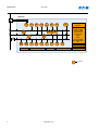
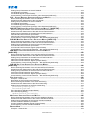
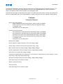
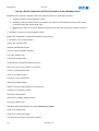
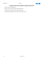
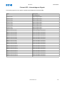
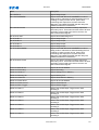
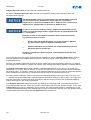
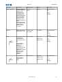
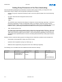
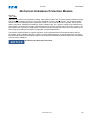
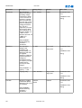
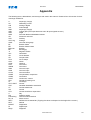
EDR-4000 EATON DISTRIBUTION RELAY
Instruction manual for installing, operating and maintaining the EDR-4000
IM02602006E
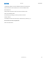
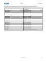
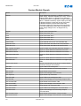
EDR-4000
EDR-4000
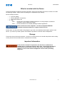
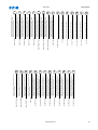
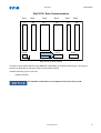
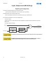
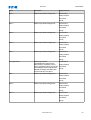
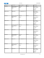
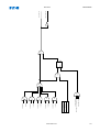
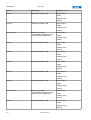
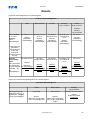
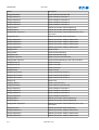
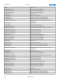
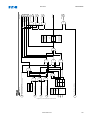
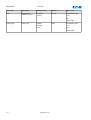
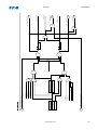
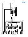
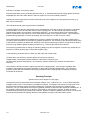
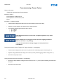
74
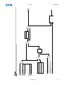
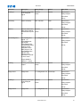
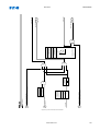
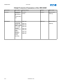
TC
3
46
50R
50
BF
51R
CTS
50P
SOTF
1
LOP
51P
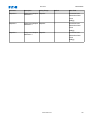
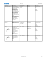
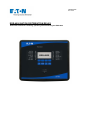
Current and Volt.:
unbalance
%THD and THD
Fund. and RMS
min./max./avg.
phasors and
angles
CLPU
55
A/D
47
4
27
A/M
59
A/M
IRIG-B00X
59N
81
U/O
81R
Zone Interlocking
78V
50X
Metering and
Statistics
51X
51V
*
Power:
Fund. and RMS
MVA, Mwatt, Mvar,
PF
Event recorder
Breaker Wear
Disturbance recorder
Fault recorder
standard
2
www.eaton.com
EDR-4000
IM02602006E
KEY FEATURES, FUNCTIONS AND BENEFITS.................................................................................................12
General Description.......................................................................................................................................12
Features.........................................................................................................................................................13
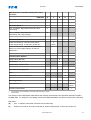
Protection Features...........................................................................................................................13
Metering Features............................................................................................................................14
Monitoring Features..........................................................................................................................14
Communication Features...................................................................................................................14
Protection and Control Functions.........................................................................................................15
COMMENTS ON THE MANUAL...................................................................................................................17
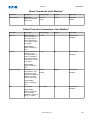
What Is Included with the Device...................................................................................................................21
Storage..........................................................................................................................................................21
Important Information ....................................................................................................................................21
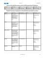
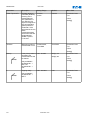
Symbols.........................................................................................................................................................22
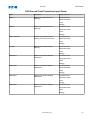
Genral Conventions.......................................................................................................................................26
DEVICE...............................................................................................................................................27
Device Planning.............................................................................................................................................27
Device Planning Parameters of the Device....................................................................................................28
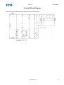
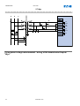
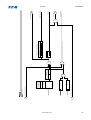
Control Wiring Diagram.................................................................................................................................31
Wiring Diagrams.............................................................................................................................32
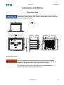
INSTALLATION AND WIRING......................................................................................................................33
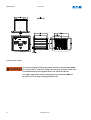
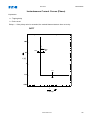
Three-Side-View............................................................................................................................................33
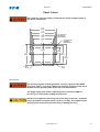
Panel Cutout..................................................................................................................................................35
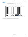
Overview of Slots - Assembly Groups............................................................................................................36
Grounding......................................................................................................................................37
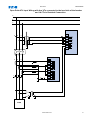
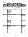
Typical Connection Diagrams........................................................................................................................38
Wye VTs and 5 A CTs in Residual Connection.......................................................................................38
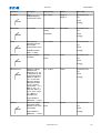
Wye Input Wiring with Aux VX input connected to the load side of the Breaker and 1A CTs in Residual Connection
.......................................................................................................................................................39
Open Delta VTs Input Wiring and 1 A CTs in Residual Connection............................................................40
Open Delta VTs Input Wiring with Aux VTs connected to the load side of the breaker and 1A CTs in Residual
Connection........................................................................................................................................41
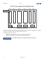
Slot X1: Power Supply Card with Digital Inputs..............................................................................................42
DI-8 X - Power Supply and Digital Inputs...............................................................................................43
Slot X2: Relay Output Card, Zone Interlock...................................................................................................45
RO-ZI X - Relay Outputs and Zone Interlock...........................................................................................46
Slot X3: Current Transformer Measuring Inputs.............................................................................................48
Current Measuring Inputs and Ground Current Measuring Input.................................................................49
Common CT Wiring Configurations....................................................................................................51
CT Connection Options....................................................................................................................51
3-phase, 3-wire IG Calculated...........................................................................................................52
3-phase, 3-wire IG Measured............................................................................................................53
4-wire system, 4th CT on Neutral........................................................................................................54
4-wire System Ground Current CT Involving Neutral................................................................................55
Slot X4: Voltage Transformer Measuring Inputs.............................................................................................56
Voltage Measuring Inputs ..................................................................................................................57
Common VT Wirings........................................................................................................................59
VT Check Measuring Values...............................................................................................................59
VT Wye.........................................................................................................................................60
VT Open Delta................................................................................................................................61
Slot X5: Relay Output Card............................................................................................................................62
RO-6 X - Relay Outputs.....................................................................................................................63
Slot X100: Ethernet Interface.........................................................................................................................65
Ethernet - RJ45.................................................................................................................................66
Slot X103: Data Communication....................................................................................................................67
RS485 - Modbus® RTU....................................................................................................................68
Slot X104: IRIG-B00X and Supervision Contact............................................................................................71
System Contact and IRIG-B00X...........................................................................................................72
www.eaton.com
3
IM02602006E
EDR-4000
PC Interface - X120.......................................................................................................................................73
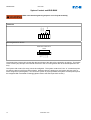
Assignment of the Null Modem Cable..................................................................................................73
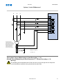
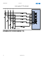
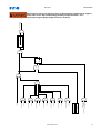
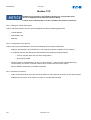
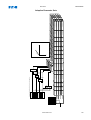
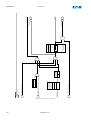
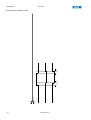
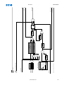
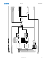
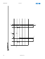
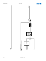
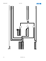
Control Wiring Diagram.................................................................................................................................74
Wiring Diagrams.............................................................................................................................75
INPUT, OUTPUT AND LED SETTINGS.........................................................................................................76
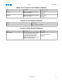
Digital Input Configuration..............................................................................................................................76
DI-8P X..........................................................................................................................................................77
Device Parameters of the Digital Inputs on DI-8P X..................................................................................77
Digital Inputs Output Signals on DI-8P X................................................................................................81
MODULE: TRIP CONTROL (TRIPCONTROL)..................................................................................................82
Direct Commands of the Trip Control Module................................................................................................84
Global Protection Parameters of the Trip Control Module..............................................................................84
Trip Control Module Input States....................................................................................................................87
Trip Control Module Signals (Output States)..................................................................................................87
Relay Output Configuration............................................................................................................................89
RO-4ZI X - Settings........................................................................................................................................92
Direct Commands of RO-4ZI X............................................................................................................92
Global Protection Parameters of RO-4ZI X.............................................................................................95
Input States of RO-4ZI X..................................................................................................................105
Signals of RO-4ZI X........................................................................................................................109
RO-6 X Settings...........................................................................................................................................110
Direct Commands of RO-6 X............................................................................................................110
Device Parameters of RO-6 X...........................................................................................................114
Input States of RO-6 X.....................................................................................................................128
Signals of RO-6 X..........................................................................................................................134
LED Configuration........................................................................................................................................135
The »System OK« LED ...............................................................................................................................138
LED Settings................................................................................................................................................139
Device Parameters of the LEDs..........................................................................................................139
LED Input States.............................................................................................................................151
FRONT PANEL....................................................................................................................................156
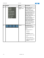
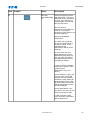
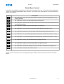
Basic Menu Control......................................................................................................................................161
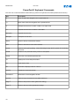
PowerPort-E Keyboard Commands.............................................................................................................162
POWERPORT-E..................................................................................................................................163
Installation of PowerPort-E...........................................................................................................................163
Un-installing PowerPort-E............................................................................................................................163
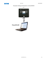
Setting up the Serial Connection PC - Device..............................................................................................164
Set Up a Connection Via Serial Interface Under Windows 2000............................................................164
Set Up a Serial Connection Via Serial Interface Under Windows XP........................................................166
Set Up a Serial Connection Via Serial Interface Under Windows Vista.....................................................168
Calling Up Web Site While Connected to a Device.............................................................................170
Establishing the Serial Connection Via a USB-/RS232-Adapter...............................................................170
Set-up a Connection via Ethernet - TCP/IP...........................................................................................171
Set-up a Connection via Modbus Tunnel.............................................................................................173
PowerPort-E Troubleshooting.............................................................................................................175
PowerPort-E Persistent Connection Problems.........................................................................................177
Loading of Device Data When Using PowerPort-E......................................................................................178
Restoring Device Data When Using PowerPort-E........................................................................................179
Backup and Documentation When Using PowerPort-E...............................................................................179
Printing of Device Data When Using PowerPort-E (Setting List).................................................................180
Exporting Data as a “txt” File Via PowerPort-E......................................................................................180
Off-line Device Planning Via PowerPort-E...................................................................................................181
MEASURING VALUES............................................................................................................................182
Read Out Measured Values.........................................................................................................................182
Read Out of Measured Values Via PowerPort-E.....................................................................................182
Current - Measured Values..........................................................................................................................182
Voltage - Measured Values..........................................................................................................................184
Power - Measured Values............................................................................................................................187
4
www.eaton.com
EDR-4000
IM02602006E
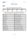
ENERGY COUNTER..............................................................................................................................189
Direct Commands of the Energy Counter Module .......................................................................................189
Signals of the Energy Counter Module (States of the Outputs)....................................................................189
STATISTICS........................................................................................................................................190
Read Out Statistics......................................................................................................................................190
Statistics to Be Read Out Via PowerPort-E............................................................................................190
Statistics (Configuration)..............................................................................................................................191
Statistics (Configuration) Via PowerPort-E.............................................................................................191
Direct Commands........................................................................................................................................192
Global Protection Parameters of the Statistics Module................................................................................192
States of the Inputs of the Statistics Module................................................................................................193
Signals of the Statistics Module...................................................................................................................193
Counters of the Module Statistics.................................................................................................................193
Current - Statistic Values...................................................................................................................194
Voltage - Statistic Values..................................................................................................................197
Power - Statistic Values....................................................................................................................201
RESETS............................................................................................................................................203
Manual Acknowledgment.............................................................................................................................205
Manual Acknowledgment Via PowerPort-E..........................................................................................205
External Acknowledgments..........................................................................................................................206
External Acknowledge Via PowerPort-E...............................................................................................206
External LED - Acknowledgment Signals..............................................................................................207
MANUAL RESETS................................................................................................................................208
Manual Resets Via PowerPort-E..................................................................................................................208
ASSIGNMENT LIST...............................................................................................................................209
STATUS DISPLAY.................................................................................................................................235
Status Display via PowerPort E....................................................................................................................235
OPERATING PANEL (HMI)....................................................................................................................236
Special Parameters of the Panel..................................................................................................................236
Direct Commands of the Panel....................................................................................................................236
Global Protection Parameters of the Panel..................................................................................................236
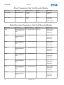
MODULE: DISTURBANCE RECORDER........................................................................................................237
Read Out of Disturbance Records...............................................................................................................241
To Read Out the Disturbance Recorder with PowerPort-E.........................................................................241
Deleting Disturbance Records.....................................................................................................................242
Deleting Disturbance Records Via PowerPort-E .....................................................................................242
Direct Commands of the Disturbance Recorder Module..............................................................................243
Global Protection Parameters of the Disturbance Recorder Module............................................................243
Disturbance Recorder Module Input States..................................................................................................245
Disturbance Recorder Module Signals.........................................................................................................245
Special Parameters of the Disturbance Recorder........................................................................................246
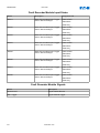
MODULE: FAULT RECORDER..................................................................................................................247
Read Out the Fault Recorder.......................................................................................................................248
To Read Out the Fault Recorder Via PowerPort-E...................................................................................248
Direct Commands of the Fault Recorder Module.........................................................................................250
Global Protection Parameters of the Fault Recorder Module.......................................................................250
Fault Recorder Module Input States.............................................................................................................252
Fault Recorder Module Signals....................................................................................................................252
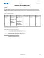
MODULE: EVENT RECORDER.................................................................................................................253
Read Out the Event Recorder......................................................................................................................254
To Read Out the Event Recorder via PowerPort-E...................................................................................254
Direct Commands of the Event Recorder Module........................................................................................255
Event Recorder Module Signals...................................................................................................................255
MODULE: MODBUS® (MODBUS)............................................................................................................256
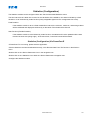
Modbus® Protocol Configuration.................................................................................................................256
Device Planning Parameters of the Modbus................................................................................................256
Modbus RTU................................................................................................................................................257
Modbus TCP................................................................................................................................................258
Direct Commands of the Modbus®..............................................................................................................259
www.eaton.com
5
IM02602006E
EDR-4000
Global Protection Parameters of the Modbus®............................................................................................259
Modbus® Module Signals (Output States)..................................................................................................263
Modbus® Module Values.............................................................................................................................264
PARAMETERS.....................................................................................................................................265
Parameter Definitions..................................................................................................................................265
Device Parameters..........................................................................................................................265
System Parameters..........................................................................................................................265
Protection Parameters......................................................................................................................265
Device Planning Parameters.............................................................................................................266
Direct Commands..........................................................................................................................266
State of the Module Inputs...............................................................................................................266
Signals........................................................................................................................................266
Adaptive Parameter Sets..................................................................................................................267
Adaptive Parameters via HMI......................................................................................................................269
Adaptive Parameter Set Activation Signals..........................................................................................273
Operational Modes (Access Authorization)..................................................................................................274
Operational Mode – »Display Only«.................................................................................................274
Operation Mode – »Parameter Setting and Planning«............................................................................274
Password.....................................................................................................................................................275
Password Entry at the Panel.............................................................................................................275
Password Changes........................................................................................................................275
Password Forgotten .......................................................................................................................275
Changing of Parameters - Example.............................................................................................................276
Changing of Parameters When Using the PowerPort-E - Example.............................................................277
Protection Parameters ................................................................................................................................280
Setting Groups.............................................................................................................................................280
Setting Group Switch......................................................................................................................280
Setting Group Switch Via PowerPort-E................................................................................................281
Copying Setting Groups (Parameter Sets) Via PowerPort-E......................................................................282
Comparing Setting Groups Via PowerPort-E.........................................................................................282
Comparing Parameter Files Via PowerPort-E..............................................................................................283
Converting Parameter Files Via PowerPort-E..............................................................................................283
SYSTEM PARAMETERS..........................................................................................................................284
BLOCKING.........................................................................................................................................287
Permanent Blocking.....................................................................................................................................287
Temporary Blocking.....................................................................................................................................287
To Activate or Deactivate the Tripping Command of a Protection Module....................................................290
Activate, Deactivate Respectively to Block Temporary Protection Functions...............................................291
MODULE: PROTECTION (PROT)..............................................................................................................293
How to Block All Protective and Supervisory Functions................................................................................293
Direct Commands of the Protection Module.................................................................................................300
Global Protection Parameters of the Protection Module...............................................................................300
Protection Module Input States....................................................................................................................301
Protection Module Signals (Output States)..................................................................................................301
Protection Module Values.............................................................................................................................302
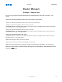
BREAKER (MANAGER)..........................................................................................................................303
Principle – General Use...............................................................................................................................303
Configuration of a Breaker...........................................................................................................................304
Assignment of the Trip Commands..............................................................................................................305
50P- DEFT OVERCURRENT PROTECTION MODULE [ANSI 50P]................................................................306
Device Planning Parameters of the 50P Module..........................................................................................308
Global Protection Parameters of the 50P Module........................................................................................308
Setting Group Parameters of the 50P Module..............................................................................................310
50P Module Input States..............................................................................................................................312
50P Module Signals (Output States)............................................................................................................313
Commissioning: Overcurrent Protection, Non-directional [ANSI 50P]..........................................................314
51P - INV OVERCURRENT-PROTECTION MODULE [ANSI 51P]..................................................................315
Device Planning Parameters of the 51P Module..........................................................................................317
Global Protection Parameters of the 51P Module........................................................................................317
6
www.eaton.com
EDR-4000
IM02602006E
Setting Group Parameters of the 51P Module..............................................................................................319
51P Module Input States..............................................................................................................................322
51P Module Signals (Output States)............................................................................................................323
Commissioning: Overcurrent Protection, Non-directional [ANSI 51P]..........................................................324
51V – VOLTAGE RESTRAINT OVERCURRENT-PROTECTION MODULE................................................................325
Device Planning Parameters of the 51V Module..........................................................................................327
Global Protection Parameters of the 51V Module........................................................................................327
Setting Group Parameters of the 51V Module..............................................................................................329
51V Module Input States..............................................................................................................................332
51V Module Signals (Output States)............................................................................................................333
Commissioning: Overcurrent Protection, Non-directional [ANSI 51P]..........................................................334
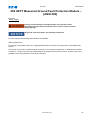
50X DEFT MEASURED GROUND FAULT PROTECTION MODULE – [ANSI 50X]..............................................335
Device Planning Parameters of the 50X Ground Fault Protection................................................................337
Global Protection Parameters of the 50X Ground Fault Protection..............................................................337
Setting Group Parameters of the 50X Ground Fault Protection...................................................................339
50X Ground Fault Protection Input States....................................................................................................341
50X Ground Fault Protection Signals (Output States)..................................................................................342
Commissioning: Ground Fault Protection – Non-directional [ANSI 50X]......................................................342
51X INV MEASURED GROUND FAULT PROTECTION MODULE [ANSI 51X]....................................................343
Device Planning Parameters of the 51X Ground Fault Protection................................................................345
Global Protection Parameters of the 51X Ground Fault Protection..............................................................345
Setting Group Parameters of the 51X Ground Fault Protection...................................................................347
51X Ground Fault Protection Input States....................................................................................................350
51X Ground Fault Protection Signals (Output States)..................................................................................351
Commissioning: Ground Fault Protection – Non-directional [ANSI 51X]......................................................351
50R DEFT CALCULATED GROUND FAULT PROTECTION MODULE
[ANSI 50R].......................................................................................................................................352
Device Planning Parameters of the 50R Ground Fault Protection................................................................354
Global Protection Parameters of the 50R Ground Fault Protection..............................................................354
Setting Group Parameters of the 50R Ground Fault Protection...................................................................356
50R Ground Fault Protection Input States....................................................................................................358
50R Ground Fault Protection Signals (Output States)..................................................................................359
Commissioning: Ground Fault Protection – Non-directional [ANSI 50R]......................................................359
51R INV CALCULATED GROUND FAULT PROTECTION MODULE
[ANSI 51R].......................................................................................................................................360
Device Planning Parameters of the 51R Ground Fault Protection................................................................362
Global Protection Parameters of the 51R Ground Fault Protection..............................................................362
Setting Group Parameters of the 51R Ground Fault Protection...................................................................364
51R Ground Fault Protection Input States....................................................................................................367
51R Ground Fault Protection Signals (Output States)..................................................................................368
Commissioning: Ground Fault Protection – Non-directional [ANSI 51R]......................................................368
ZONE INTERLOCKING............................................................................................................................369
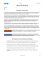
Principle – General Use...............................................................................................................................369
Description of the Functions and Features...................................................................................................369
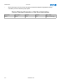
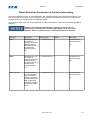
Device Planning Parameters of the Zone Interlocking.................................................................................370
Global Protection Parameters of the Zone Interlocking................................................................................371
Setting Group Parameters of the Zone Interlocking.....................................................................................372
Zone Interlocking Output Logic [X2]...................................................................................................375
Zone Interlocking Input States...........................................................................................................380
Zone Interlocking Signals (Output States)....................................................................................................380
Zone Interlocking Wiring..............................................................................................................................381
Hardware Terminals for Zone Interlocking...........................................................................................383
46-CURRENT UNBALANCE PROTECTION MODULE.......................................................................................385
Device Planning Parameters of the Current Unbalance Module..................................................................387
Global Protection Parameters of the Current Unbalance Module.................................................................387
Setting Group Parameters of the Current Unbalance Module......................................................................388
Current Unbalance Module Input States......................................................................................................390
Current Unbalance Module Signals (Output States).....................................................................................390
Commissioning: Current Unbalance Module................................................................................................391
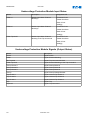
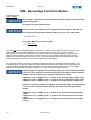
BREAKER WEAR.................................................................................................................................393
Principle – General Use...............................................................................................................................393
www.eaton.com
7
IM02602006E
EDR-4000
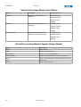
Device Planning Parameters of the Breaker Wear Module..........................................................................393
Global Protection Parameters of the Breaker Wear Module........................................................................393
Breaker Wear Input States...........................................................................................................................394
Breaker Wear Signals (Output States).........................................................................................................395
Breaker Wear Counter Values.....................................................................................................................395
Breaker Wear Values...................................................................................................................................395
Direct Commands of the Breaker Wear Module..........................................................................................396
LOP – LOSS OF POTENTIAL.................................................................................................................397
Device Planning Parameters of the LOP Module.........................................................................................399
Global Protection Parameters of the LOP Module.......................................................................................399
Setting Group Parameters of the LOP Module.............................................................................................400
LOP Module Input States.............................................................................................................................402
LOP Module Signals (Output States)...........................................................................................................402
Commissioning: Loss of Potential................................................................................................................403
SOTF - PROTECTION MODULE: SWITCH ONTO FAULT...............................................................................404
Device Planning Parameters of the Switch Onto Fault Module....................................................................406
Global Protection Parameters of the Switch Onto Fault Module...................................................................406
Setting Group Parameters of the Switch Onto Fault Module........................................................................408
Switch Onto Fault Module Input States........................................................................................................410
Signals of the Switch Onto Fault Module (Output States)............................................................................410
Commissioning: Switch Onto Fault [ANSI 50HS].........................................................................................411
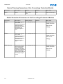
CLPU - SUPERVISION MODULE COLD LOAD PICKUP.................................................................................412
Device Planning Parameters of the Cold Load Pickup Module....................................................................416
Global Protection Parameter of the Cold Load Pickup Module....................................................................416
Set Parameters of the Cold Load Pickup Module.........................................................................................417
States of the Inputs of the Cold Load Pickup Module...................................................................................419
Signals of the Cold Load Pickup Module (States of the Outputs).................................................................419
Commissioning of the Cold Load Pickup Module.........................................................................................420
27M - UNDERVOLTAGE PROTECTION MODULE...........................................................................................422
Device Planning Parameters of the Undervoltage Protection Module..........................................................425
Global Protection Parameters of the Undervoltage Protection Module........................................................425
Setting Group Parameters of the Undervoltage Protection Module..............................................................426
Undervoltage Protection Module Input States..............................................................................................430
Undervoltage Protection Module Signals (Output States)............................................................................430
Commissioning: Undervoltage Protection [27M]..........................................................................................431
59M - OVERVOLTAGE PROTECTION MODULE............................................................................................432
Device Planning Parameters of the Overvoltage Protection Module............................................................434
Global Protection Parameters of the Overvoltage Protection Module..........................................................434
Setting Group Parameters of the Overvoltage Protection Module................................................................435
Overvoltage Protection Module Input States................................................................................................439
Overvoltage Protection Module Signals (Output States)..............................................................................439
Commissioning: Overvoltage Protection [59M]............................................................................................440
27A - AUXILIARY UNDERVOLTAGE PROTECTION MODULE.............................................................................441
Device Planning Parameters of the Aux. Undervoltage Module...................................................................443
Global Protection Parameters of the Aux. Undervoltage Module..................................................................443
Setting Group Parameters of the Aux. Undervoltage Module.......................................................................444
Aux. Undervoltage Module Input States.......................................................................................................446
Aux. Undervoltage Module Signals (Output States).....................................................................................447
Commissioning: Aux. Undervoltage.............................................................................................................448
59A – AUXILIARY OVERVOLTAGE PROTECTION MODULE..............................................................................449
Device Planning Parameters of the Aux. Overvoltage Module.....................................................................451
Global Protection Parameters of the Aux. Overvoltage Module....................................................................451
Setting Group Parameters of the Aux. Overvoltage Module.........................................................................452
Aux. Overvoltage Module Input States.........................................................................................................454
Aux. Overvoltage Module Signals (Output States).......................................................................................455
Commissioning: Aux. Overvoltage...............................................................................................................456
59N - NEUTRAL OVERVOLTAGE PROTECTION............................................................................................457
Device Planning Parameters of the Neutral Overvoltage Module.................................................................459
Global Protection Parameters of the Neutral Overvoltage Module...............................................................459
Setting Group Parameters of the Neutral Overvoltage Module....................................................................460
Neutral Overvoltage Module Input States.....................................................................................................462
8
www.eaton.com
EDR-4000
IM02602006E
Neutral Overvoltage Module Signals (Output States)...................................................................................462
Commissioning: Neutral Overvoltage Protection..........................................................................................463
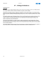
47 – VOLTAGE UNBALANCE..................................................................................................................464
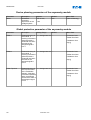
Device planning parameters of the asymmetry module ..............................................................................466
Global protection parameter of the asymmetry-module...............................................................................466
Parameter set parameters of the asymmetry module..................................................................................467
States of the inputs of the asymmetry module............................................................................................469
Signals of the asymmetry module (states of the outputs).............................................................................469
Commissioning: Asymmetry Protection........................................................................................................470
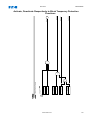
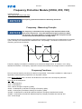
FREQUENCY PROTECTION MODULE [81O/U, 81R, 78V]...........................................................................471
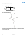
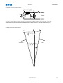
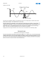
Frequency - Measuring Principle..................................................................................................................471
Frequency Functions....................................................................................................................................471
Working Principle..........................................................................................................................472
Working Principle..........................................................................................................................474
Working Principle..........................................................................................................................476
Working Principle..........................................................................................................................478
Working Principle..........................................................................................................................484
Device Planning Parameters of the Frequency Protection Module..............................................................486
Global Protection Parameters of the Frequency Protection Module.............................................................486
Setting Group Parameters of the Frequency Protection Module..................................................................487
Frequency Protection Module Input States..................................................................................................490
Frequency Protection Module Signals (Output States).................................................................................490
Commissioning: Overfrequency [ANSI 81O]................................................................................................491
Commissioning: Underfrequency [ANSI 81U]..............................................................................................491
Commissioning: 81R Rate of Change (df/dt)................................................................................................492
Commissioning: 81U and Rate of Change (f< and -df/dt)............................................................................493
Commissioning: 81O and Rate of Change (f> and df/dt).............................................................................493
Commissioning: 81UΔR – Underfrequency and DF/DT...............................................................................494
Commissioning: 81OΔR – Overfrequency and DF/DT.................................................................................494
Commissioning: Vector Surge 78V..............................................................................................................495
55A AND 55D - PF PROTECTION MODULE..............................................................................................496
Device Planning Parameters of the Power Factor Module...........................................................................498
Global Protection Parameter of the Power Factor Module...........................................................................498
Set Parameters of the Power Factor Module...............................................................................................499
States of the Inputs of the Power Factor Module.........................................................................................501
Signals of the Power Factor Module (States of the Outputs)........................................................................501
Commissioning: Power Factor.....................................................................................................................502
EXP PROTECTION MODULE – EXTERNAL PROTECTION................................................................................504
Device Planning Parameters of the External Protection Module..................................................................506
Global Protection Parameters of the External Protection Module.................................................................506
Setting Group Parameters of the External Protection Module......................................................................507
External Protection Module Input States......................................................................................................508
External Protection Module Signals (Output States)....................................................................................508
Commissioning: External Protection............................................................................................................509
BF SUPERVISION MODULE – CIRCUIT BREAKER FAILURE PROTECTION [ANSI 50BF]......................................510
Principle – General Use...............................................................................................................................510
Trigger Modes..............................................................................................................................................510
Device Planning Parameters of the BF Module............................................................................................512
Global Protection Parameters of the BF Module..........................................................................................512
Setting Group Parameters of the BF Module...............................................................................................513
BF Module Input States................................................................................................................................514
BF Module Signals (Output States)..............................................................................................................514
Commissioning: Circuit Breaker Failure Protection [ANSI 50BF].................................................................517
IRIG-B00X.....................................................................................................................................518
Principle - General Use................................................................................................................................518
Function.......................................................................................................................................................519
IRIG-B Control Commands..........................................................................................................................519
Device Planning Parameters of the IRIG-B00X............................................................................................519
Direct Commands of the IRIG-B00X............................................................................................................519
Global Protection Parameters of the IRIG-B00X..........................................................................................520
Signals of the IRIG-B00X (Output States)....................................................................................................523
www.eaton.com
9
IM02602006E
EDR-4000
IRIG-B00X Values........................................................................................................................................524
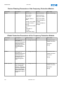
CTS-SUPERVISION MODULE – CURRENT TRANSFORMER SUPERVISION............................................................525
Device Planning Parameters of the Current Transformer Supervision.........................................................527
Global Protection Parameter of the Current Transformer Supervision.........................................................527
Setting Group Parameters of the Current Transformer Supervision.............................................................528
Current Transformer Supervision Input States.............................................................................................530
Current Transformer Supervision Signals (Outputs States).........................................................................530
Commissioning: Current Transformer Failure Supervision...........................................................................531
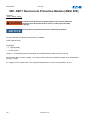
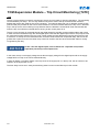
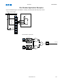
TCM-SUPERVISION MODULE – TRIP CIRCUIT MONITORING [74TC]..............................................................532
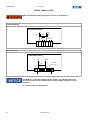
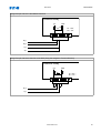
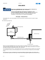
One Breaker Application Examples..............................................................................................................533
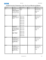
Device Planning Parameters of the Trip Circuit Monitoring Module..............................................................534
Global Protection Parameters of the Trip Circuit Monitoring Module............................................................535
Setting Group Parameters of the Trip Circuit Monitoring Module.................................................................536
Trip Circuit Monitoring Module Input States..................................................................................................537
Trip Circuit Monitoring Module Signals (Output States)................................................................................537
Commissioning: Trip Circuit Monitoring for Breakers [74TC].......................................................................538
DEVICE PARAMETERS...........................................................................................................................539
Date and Time.............................................................................................................................................539
Synchronize Date and Time Via PowerPort-E........................................................................................539
Version.........................................................................................................................................................539
Version Via PowerPort-E..............................................................................................................................539
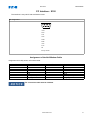
TCP/IP Settings...........................................................................................................................................540
Direct Commands of the System Module.....................................................................................................541
Global Protection Parameters of the System...............................................................................................541
System Module Input States........................................................................................................................545
System Module Signals................................................................................................................................546
Special Values of the System Module..........................................................................................................548
COMMISSIONING..................................................................................................................................549
Commissioning/Protection Test....................................................................................................................550
Decommissioning – Removing the Plug from the Relay..............................................................................551
SERVICE...........................................................................................................................................552
General.......................................................................................................................................552
Maintenance Mode......................................................................................................................................552
Principle – General Use...............................................................................................................................552
Before Use...................................................................................................................................................553
How to Use the Maintenance Mode.............................................................................................................553
Forcing the Relay Output Contacts..............................................................................................................555
Principle – General Use..................................................................................................................555
Disarming the Relay Output Contacts..........................................................................................................556
Principle – General Use..................................................................................................................556
SELF SUPERVISION..............................................................................................................................557
Error Messages / Codes..............................................................................................................................559
TECHNICAL DATA................................................................................................................................560
Climatic Environmental Conditions...............................................................................................................560
Degree of Protection EN 60529...................................................................................................................560
Routine Test.................................................................................................................................................560
Housing........................................................................................................................................................561
Current and Ground Current Measurement.................................................................................................561
Plug-in Connector with Integrated Short-Circuiter
(Conventional Current Inputs)..........................................................................................................................562
Voltage and Residual Voltage Measurement................................................................................................563
Frequency Measurement.............................................................................................................................563
Voltage Supply.............................................................................................................................................563
Power Consumption.....................................................................................................................................563
Display.........................................................................................................................................................564
Front Interface RS232..................................................................................................................................564
Real Time Clock...........................................................................................................................................564
Digital Inputs................................................................................................................................................564
Relay Outputs..............................................................................................................................................565
Supervision Contact (SC).............................................................................................................................565
Time Synchronization IRIG-B00X.................................................................................................................565
10
www.eaton.com
EDR-4000
IM02602006E
Zone Interlocking.........................................................................................................................................565
RS485*........................................................................................................................................................566
Boot Phase..................................................................................................................................................566
STANDARDS.......................................................................................................................................567
Approvals.....................................................................................................................................................567
Design Standards........................................................................................................................................567
High Voltage Tests (IEC 60255-6)................................................................................................................567
EMC Immunity Tests....................................................................................................................................568
EMC Emission Tests....................................................................................................................................569
Environmental Tests.....................................................................................................................................570
Mechanical Tests.........................................................................................................................................571
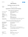
SPECIFICATIONS..................................................................................................................................572
Specifications of the Real Time Clock..........................................................................................................572
Specifications of the Measured Value Acquisition........................................................................................572
Phase and Ground Current Measuring...............................................................................................572
Phase-to-ground and Residual Voltage Measurement..............................................................................572
Frequency measurement..................................................................................................................572
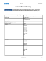
Protection Elements Accuracy.....................................................................................................................573
APPENDIX.........................................................................................................................................579
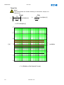
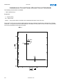
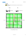
Instantaneous Current Curves (Phase)........................................................................................................585
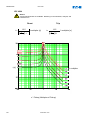
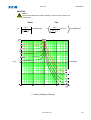
Time Current Curves (PHASE)....................................................................................................................586
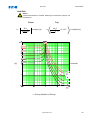
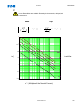
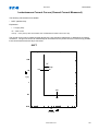
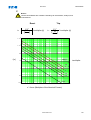
Instantaneous Current Curves (Ground Current Calculated).......................................................................598
Instantaneous Current Curves (Ground Current Measured)........................................................................599
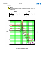
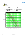
Time Current Curves (Gound Current).........................................................................................................600
d1a3398642356dad58d557d2877ae1b6
a52dfc3577bd5b2a214a254a0d0c6541
RMS Handoff: 0
File: C:\p4_data\deliverEDR-4000\generated\EDR-4000_user_manual_eaton_en.odt.odt
This manual applies to devices (version):
Version 1.0.b
Build: 10085
www.eaton.com
11
IM02602006E
EDR-4000
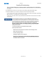
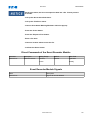
Key Features, Functions and Benefits
•
•
•
•
•
•
•
•
•
•
•
•
•
•
Microprocessor-based protection with monitoring and control for medium voltage main and feeder
applications.
Current, voltage, and frequency protection for electrical power distribution systems.
Complete metering of voltage, currents, power, energy, minimum/maximum and demand* functions.
Complete metering, protection, and control in a single compact case to reduce panel space, wiring and
costs.
Integral test function reduces maintenance time and expense.
Zone selective interlocking improves coordination and tripping time, and saves money compared to a
traditional bus differential scheme.
Programmable logic control functions for main-tie-main transfer schemes*.
Reduce trouble shooting time and maintenance costs- Trip and event recording in non-volatile memory
provides detailed information for analysis and system restoration. 6000 cycles of waveform capture aids
in post fault analysis (viewable using Powerport-E software)
Minimum replacement time- Removable terminal blocks ideal in industrial environments
Front RS-232 port and Powerport-E software provides local computer access and user-friendly windows
based interface for relay settings, configuration, and data retrieval.
Breaker open/close from relay faceplate* or remotely via communications.
Fast an easy troubleshooting, improved maintenance procedures and increased device security.
Provides detailed traceability for system configuration changes
Relays self-diagnostics and reporting improves uptime and troubleshooting.
Breaker trip circuit monitoring improves the reliability of the breaker operation.
*=future
General Description
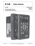
Eaton’s EDR-4000 distribution protection relay is a multi-functional, microprocessor-based relay for feeder
circuits of all voltage levels. It may be used as the primary protection on feeders, mains and tie circuit breaker
applications; or as backup protection for transformers, high voltage lines and differential protection. The relay is
most commonly used on medium voltage switchgear applications
The EDR-4000 feeder protection relay provides complete current, voltage, and frequency protection and
metering in a single, compact case. The relay has four current inputs rated for either 5 amperes or 1 ampere
and four voltage inputs. Three of the voltage inputs are to be connected to the 3-phase power voltage for voltage
protection and for metering. They can be connected in wye-ground or open delta configuration. The fourth
voltage is for independent single-phase undervoltage/overvoltage protection, or ground protection for an
ungrounded system.
The maintenance mode password protected soft key, can be used for arc flash mitigation to change to an
alternate settings group, set to have instantaneous elements only. The multiple setting groups can also be
changed, via communications or a digital input.
An integral keypad and display is provided for direct user programming and retrieval of data without the need of
a computer. 14 programmable LEDs provide quick indication of relay status.
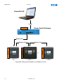
A front port is provided for direct computer connection. An RS-485 communication port on the back is standard
for local area networking using Modbus-RTU. An optional Ethernet port and protocols are available.
The EDR-4000 distribution protection relay includes programmable logic functions*. Logic gates and timers may
be defined and arranged for customized applications. Programmable logic control functions make the EDR-4000
relay ideally suited for main-tie-main and main 1/main 2 transfer schemes. Flash memory is used for the
programming and all settings are stored in nonvolatile memory. The relay allows for four preprogrammed setting
groups which can be activated through software or contact input.
Flash memory is used for the programming and all settings are stored in nonvolatile memory. The relay allows
for four preprogrammed setting groups which can be activated through software, the display or a contact input.
12
www.eaton.com
EDR-4000
IM02602006E
The EDR-4000 distribution protection relay has mass memory for data storage and a real-time clock with 1 ms
time resolution. The relay will log 300 sequence of event records, 20 detailed trip logs, minimum/maximum
values, load profiles, breaker wear information and oscillography data.
The EDR-4000 has eight programmable binary inputs, 2 normally opened and 8 Form C heavy duty outputs and
one form C signal alarm relay. It can be powered from 19 Vdc to 300 Vdc or 40 Vac to 250 Vac auxiliary power.
Features
Protection Features
Phase overcurrent elements
•
Three instantaneous elements with timers ( 50P[1], 50P[2], and 50P[3])
•
Three inverse time overcurrent elements (51P[1], 51P[2], and 51P[3])
•
11 standard curves
•
Instantaneous or time delay reset
Ground overcurrent elements
•
Two instantaneous measured elements with timers (50X[1], and 50X[2])
•
Two instantaneous calculated elements with timers (50R[1], and 50R[2])
•
Two inverse time overcurrent measured elements (51X[1], and 51X[2])
•
Two inverse time overcurrent calculated elements (51R[1], and 51R[2])
•
11 standard curves
•
Instantaneous or time delay reset
Breaker failure (50BF)
Phase unbalance negative sequence overcurrent (46[1], 46[2])).
Phase voltage unbalance and sequence protection (47[1], 47[2]).
Main 3-phase under/overvoltage (27M[1], 27M[2], 59M[1], 59M[2])
Auxiliary single-phase under/overvoltage (27A[1], 27A[2], 59A[1], 59A[2])
Ground fault overvoltage relay (59N[1], 59N[2])
6 Frequency elements that can be assigned to: over frequency, under frequency, rate of change, or vector
surge (81[1], 81[2], 81[3], 81[4], 81[5], 81[6])
Apparent and displacement power factor (55A[1], 55A[2], 55D[1], 55D[2]).
Zone interlocking for bus protection (87B).
Switch onto fault protection
Cold load pickup
Zone interlocking for bus protection (87B).
www.eaton.com
13
IM02602006E
EDR-4000
Metering Features
•
•
•
•
•
•
•
•
•
•
•
•
•
•
•
Amperes: Positive, negative and zero sequence.
Ampere demand.
Volts: Positive, negative and zero sequence.
Phase angles.
Volt-amperes and VA demand.
Watts and kW demand.
kWh (forward, reverse, net).
Vars and kvar demand.
kvarh (lead, leg and net).
Power factor.
Frequency.
% THD V and I.
Magnitude THD V and I.
Minimum/maximum recording.
Trending (load profile over time)*
*=future
Monitoring Features
•
•
•
•
•
•
Trip coil monitor
Breaker wear primary and secondary (accumulated interrupted current).
Oscillography (6000 cycles total).
Fault data logs (up to 20 events).
Sequence of events report (up to 300 events).
Clock (1 ms time stamping).
Communication Features
•
•
•
•
•
•
•
•
•
•
•
•
14
Local HMI.
Password protected.
Addressable.
IRIG-B
Local communication port.
Remote communication port:
RS-232
RS-485
Protocols:
Modbus-RTU
Modbus-TCP (Optional)
Configuration software
www.eaton.com
EDR-4000
IM02602006E
Protection and Control Functions
The Eaton’s EDR-4000 distribution protection relay has been designed for maximum user flexibility and
simplicity. The base relay includes all the standard current and voltage protection and metering functions.
Overcurrent Protection
The EDR-4000 distribution protection relay provides complete 3-phase and ground overcurrent protection. There
are 8 independent ground overcurrent elements. The ground elements “X” use the independently measured
ground (or neutral) current from a separate current-sensing input. The ground elements “R” uses a calculated
3Io residual current obtained from the sum of the 3-phase currents. This calculated current could be used for
either the neutral or ground current in a 3-phase, 4-wire system. Each of the phase and ground overcurrent
elements can be selected to operate based on fundamental or RMS current.
Voltage Restrained Overcurrent
Voltage restraint reduces the overcurrent pickup level (51P[3]). This modification of the pickup overcurrent level
is compared to the corresponding phase input voltage. The EDR-4000 uses the simple linear model below to
determine the effective pickup value.
Inverse-Time Characteristics
There are 11 user-selectable inverse-time overcurrent curve characteristics.
The user can select from the ANSI, IEC or thermal curve families and can select instantaneous or time delay
reset characteristics.
Breaker Failure
The EDR-4000 distribution protection relay includes a breaker failure (50BF, 62BF) function that can be initiated
from either an internal or external trip signal. This is an independent element that can be used to operate a
lockout relay or trip an upstream breaker. The timer must be longer than the breaker operating time and the
protective function reset times.
Voltage Protection
The EDR-4000 distribution protection relay has four voltage-input circuits. There is a 3-phase set designated as
Main Voltage (M) and a single-phase voltage circuit designated as Auxiliary Voltage (A). Both include
undervoltage (27) and overvoltage (59) protection. The 3-phase voltage protection can be set to operate on a
single-phase, 2 out of 3 phases, or all 3-phase logic. The Main VTs also provide phase voltage
unbalance/reversal (47 negative sequence) protection. Each element has an independent threshold set point
and adjustable time delay.
Ground Voltage Protection
In high impedance grounded systems, ground fault protection is provided by the detection of zero sequence
voltage (3Vo) voltage in the neutral of the transformer by an overvoltage element (59N) connected to the
secondary of the distribution grounding transformer, or in the secondary of a Wye- Broken Delta transformer
used when the neutral is not accessible or in Delta system. In the EDR-4000 we can measure this zero
sequence voltage through the 4th voltage input; the 59N element has to be desensitized for 3rd harmonic
voltages that can be present in the system under normal operation.
www.eaton.com
15
IM02602006E
EDR-4000
Flexible Phase Rotation
The EDR-4000 distribution protection relay can be applied on either an A-B-C or A-C-B phase rotation. A user
setting permits correct operation and indication of the actual system configuration.
Frequency Protection
The EDR-4000 relay provides 6 frequency elements than can be used to detect under/over frequency, rate of
change, and a vector surge (decoupling of two systems) protection on the Main VT inputs. Each element has an
independent threshold set point and adjustable time delay.
Maintenance Mode
The Maintenance Mode can improve safety by providing a simple and reliable method to reduce fault clearing
time
and lower incident energy levels at energized panels. The Maintenance Mode allows the user to switch to more
sensitive settings via a password protected soft key, communication or via a digital Input while maintenance
work is being performed at an energized panel or device. The more sensitive settings provide greater security for
maintenance personnel and helps reduce the possibility of injury.
Monitoring and Metering
Sequence of Events Records
The EDR-4000 protection relay records a maximum of 300 events associated with the relay. An event is
classified as a change of state as detected by the relay. These include relay pickups, dropouts, trips, contact
closure, alarms, setting changes and self-diagnostic failures. Each event is date and time stamped to a 1 ms
resolution. The events are stored in a FIFO in chronological order.
Trip Log
The EDR-4000 protection relay will store a maximum of 20 trip records in a FIFO trip log. Each trip record will
be date and time stamped to a 1 ms resolution. The trip log record will include information on the type of fault,
protection elements that operated, fault location and currents and voltages at the time of the fault.
Waveform Capture
The EDR-4000 transfomer protection relay provides oscillography-recording capabilities. The relay will record all
measured signals along with the binary signals of pickup, trip, logic and contact closures. The ETR-4000 relay
can record up to 6000 cycles of data. The number of records is proportional to the size of each record; the
maximum size per record is 600 cycles. The waveform capture is initiated by up to 8 different triggers; it can also
be generated manually through the display or via communications.
Integral User Interface
The front panel user interface has a 128 x 64 pixel LCD display with background illumination for wide angle
viewing in all light conditions. 17 programmable LEDs provide quick and easy visual display of power on, mode
of operation, alarm and trip indication. Soft keys are provided for operation mode selection, scrolling through
data and settings. In addition, the relay settings and test functions are password protected.
Programmable I/O
The EDR-4000 distribution protection relay provides heavy-duty, trip-rated, 2 normally open and 8 Form C
contacts. Two isolated inputs can be used for monitoring the trip circuit. One Form C contact is dedicated to the
relay failure alarm function and is operated in a normally energized (failsafe) mode. There are eight userconfigurable discrete inputs that accept a wet contact and can operate through a wide range of power. Each
input and output is user-programmable for maximum application flexibility.
16
www.eaton.com
EDR-4000
IM02602006E
Comments on the Manual
This manual gives a general explanation of the tasks of device planning, parameter setting, installation,
commissioning, operation, and maintenance of the Eaton devices.
The manual serves as reference document for:
•
•
•
•
Engineers in the protection field;
Commissioning engineers;
Personnel dealing with the setting, testing, and maintenance of protection and control devices; and
Well trained personnel involved in electrical installations and power stations.
All functions concerning the type code will be defined. Should there be a description of any functions,
parameters, or inputs/outputs that do not apply to the device in use, please ignore that information.
All details and references are explained to the best of our knowledge and are based on our experience and
observations.
This manual describes the full featured versions of the devices, including all options.
All technical information and data included in this manual reflect their state at the time this document was issued.
Eaton Corporation reserves the right to carry out technical modifications in line with further development without
changing this manual and without previous notice. Therefore no claim can be brought based on the information
and descriptions included in this manual.
Text, graphics, and formulas do not always apply to the actual delivery scope. The drawings and graphics are
not true to scale. Eaton Corporation does not accept any liability for damage and operational failures caused by
operating errors or disregarding the directions of this manual.
No part of this manual is allowed to be reproduced or passed on to others in any form, unless Eaton Corporation
has issued advanced approval in writing.
This user manual is part of the delivery scope when purchasing the device. In case the device is passed on
(sold) to a third party, the manual has to be passed on as well.
Any repair work carried out on the device requires skilled and competent personnel with verifiable knowledge
and experienced with local safety regulations and have the necessary experience with working on electronic
protection devices and power installations.
IMPORTANT DEFINITIONS
The symbol/word combinations detailed below are designed to call the User's attention to issues that could affect
User safety and well being as well as the operating life of the device.
DANGER indicates a hazardous situation which, if not avoided, will result in
death or serious injury.
WARNING indicates a hazardous situation which, if not avoided, could
result in death or serious injury.
CAUTION, used with the safety alert symbol, indicates a hazardous
situation which, if not avoided, could result in minor or moderate injury.
CAUTION, without the safety alert symbol, is used to address practices not
related to personal injury.
www.eaton.com
17
IM02602006E
EDR-4000
NOTICE is used to address information and practices not related to
personal injury.
FOLLOW INSTRUCTIONS
Read this entire manual and all other publications pertaining to the work to
be performed before installing, operating, or servicing this equipment.
Practice all plant and safety instructions and precautions. Failure to follow
the instructions can cause personal injury and/or property damage.
PROPER USE
Any unauthorized modifications to or use of this equipment outside its
specified mechanical, electrical, or other operating limits may cause
personal injury and/or property damage, including damage to the
equipment. Any such unauthorized modifications: (1) constitute "misuse"
and/or "negligence" within the meaning of the product warranty, thereby
excluding warranty coverage for any resulting damage; and (2) invalidate
product certifications or listings.
The programmable devices subject to this manual are designed for
protection and also control of power installations and operational devices.
The devices are further designed for installation in low voltage (LV)
compartments of medium voltage (MV) switchgear panels or in decentralized protection panels. The programming and settings have to meet
all requirements of the protection concept (of the equipment that is to be
protected). The User must ensure that the device will properly recognize
and manage (e.g.: switch off the circuit breaker) on the basis of User
selected programming and settings all operational conditions (failures).
Before starting any operation and after any modification of the
programming/settings, make a documented proof that the programming
and settings meet the requirements of the protection concept.
Typical applications for this product family/device line are for example:
•
Feeder protection;
•
Mains protection;
•
Transformer Protection and
•
Machine protection.
This device is not designed for any usage beyond these applications. The
manufacturer cannot be held liable for any resulting damage. The User
alone bears the risk if this device is used for any application for which it
was not designed. As to the appropriate use of the device: the technical
data specified by Eaton Corporation has to be met.
18
www.eaton.com
EDR-4000
IM02602006E
OUT-OF-DATE PUBLICATION
This publication may have been revised or updated since this copy was
produced. To verify that you have the latest revision, be sure to check the
Eaton Corporation website:
www.eaton.com
The latest versions of most publications are available at this site.
If the User's publication is not found on the web site, please contact Eaton
Customer Support to get the latest copy.
www.eaton.com
19
IM02602006E
EDR-4000
ELECTROSTATIC DISCHARGE AWARENESS
All electronic equipment is sensitive to electrostatic discharge, some
components more than others. To protect these components from
electrostatic damage, the User must take special precautions to minimize or
eliminate electrostatic discharges.
Follow these precautions when working with or near the device.
1.
Before performing maintenance on the electronic device, discharge
the static electricity on your body to ground by touching and holding a
grounded metal object (pipes, cabinets, equipment, etc.).
2.
Avoid the build-up of static electricity on your body by not wearing
clothing made of synthetic materials. Wear cotton or cotton-blend
materials as much as possible because these do not store static
electric charges as much as synthetics.
3.
Keep plastic, vinyl, and Styrofoam materials (such as plastic or
Styrofoam cups, cup holders, cigarette packages, cellophane
wrappers, vinyl books or folders, plastic bottles, and plastic ash trays)
away from the device, the modules, and the work area as much as
possible.
4.
Do not remove any printed circuit board (PCB) from the device cabinet
unless absolutely necessary. If you must remove the PCB from the
device cabinet, follow these precautions:
•
Do not touch any part of the PCB except the edges.
•
Do not touch the electrical conductors, the connectors, or the
components with conductive devices or with your hands.
•
When replacing a PCB, keep the new PCB in the plastic, antistatic protective bag it comes in until you are ready to install
the PCB. Immediately after removing the old PCB from the
device cabinet, place it in the anti-static protective bag.
Eaton Corporation reserves the right to update any portion of this publication at any time. Information provided
by Eaton Corporation is believed to be correct and reliable. However, no responsibility is assumed by Eaton
Corporation unless otherwise expressly undertaken.
© Eaton Corporation, 2010. All Rights Reserved.
20
www.eaton.com
EDR-4000
IM02602006E
What Is Included with the Device
The device package includes all connection terminals, except communication connectors, but does not include
the fastening material. Please check the package for completeness upon delivery.
Device Package Contents:
•
•
•
•
1 – Protective Relay;
1 – Mount (Standard or Projection);
1 – Quick Start Guide; and
2 – CDs
Disk 1 - Contains the User's Manual, Modbus Datapoint List, Wiring Diagram, and Device
Template for Off-line Parameter Setting;
Disk 2 - Contains PowerPort-E and Quality Manager software applications.
Disk1 contains the device templates. The device templates MUST BE
installed to allow PowerPort-E to configure a device off-line.
Please make sure the product label, wiring diagram, type code, and materials and description pertain to this
device. If you have any doubts, please contact Eaton Corporation's Customer Service Department.
Storage
The devices must not be stored outdoors. If stored, it must be stored in an area with temperature and humidity
control (see the Technical Data section contained in this manual).
Important Information
In line with the customer’s requirement, the devices are combined in a
modular way (in compliance with the order code). The terminal assignment
of the device can be found on the top of the device (wiring diagram). In
addition, it can be found within the Appendix of this manual (see Wiring
Diagrams).
www.eaton.com
21
22
www.eaton.com
"φ "=Elements with complex functions
"gray-box".
Functional description: If the setting
value "IG.Block at VE=0" is set to
"inactive", the output 1 is active and
output 2 is inactive. If the setting value
"IG.Block at VE=0" is set to "active",
the output 2 is active and the output 1
is inactive.
Measured Values:
Internal message
Signal:
Device Planning:
Setting Value:
φ
AR.t-DP
Active
Inactive
IG.nondir Trip at
VE=0
t-DP
IG
0
<Name>.*int Alm L1
Prot.I dir fwd
<Name>
<Name>.I
2
1
Limit value monitoring (Compared to
a fixed value). Compares a value with
the fixed set limit; output value is
binary as a result of the comparision.
If the signal exceeds the limit, the
corresponding output signal becomes
"1".
Limit value monitoring with three
analog input values. Compares 3
analog values with the set limit; output
values are three different binary
values as a result of the comparision.
If the analog signal exceeds the limit I/
In, the corresponding output signal
becomes "1".
Parameter of a Module-Input (with
special values): An (1..n) output from the
list will be assigned to the input
"<name>.identifier". If the parameter is
set to "ItemNull", an "active"-signal will be
given out.
Parameter of a Module-Input with a
SelectionList/DropDown. An (1..n)
signal/output from the list or a predefined value can be selected.
Option/features to be realised in the future.
IC
IB
IA
V
<20%Vn
I/ In
No assignment,1..n
1..n,
1..n,
Assignment
VeEnableList
No assignment 1
<Name>
1..n, Assignment List
<Name>
Active
Inactive
Bkr.Latched
Direct Command
Selection List
<Name>
Adaptive Parameter
IM02602006E
EDR-4000
Symbols
www.eaton.com
Analog Value
Comparator
Analog Values
Quotient of Analog Values
Band-pass (filter)
IH2
Band-pass (filter)
IH1
Negated Output
Negated Input
Inverting
Exclusive-XR
Or
And
IH1
IH2
IH2
IH1
XOR
OR
AND
Time stage minimum pulse
width: The pulse width
<name>.t will be started if a
"1" is feed to the input. By
starting <name>.t, the
output becomes "1". If the
time is expired, the output
becomes "0" independent
from the input signal.
Edge triggered counter
+ Increment
R Reset
Time stage: A "1" at the
input starts the element. If
the time <name>.t is
expired, the output becomes
"1" too. The time stage will
be reset by "0" at the input.
Thus the output will be set to
"0" at the same time.
RS flip-flop
abcd
0 0 Unchanged
0101
1010
1101
b
a
t
1
R
+
Q
Q
Counter
t2
t1: Switch On Delay
t2: Switch Off Delay
t2
c
d
Bkr.t-TripCmd
t1
t1
Delay Timer
R1
S
t1
Delay Timer
t2
EDR-4000
IM02602006E
23
2
24
www.eaton.com
Name.TripCmd
Name.Pickup
VTS.Pickup
Bkr.Trip Bkr
Name. Fault in Projected Direction
Name. Fault in Projected Direction
IH2.Blo IG
IH2.Blo Phase C
IH2.Blo Phase B
IH2.Blo Phase A
Name.Active
Name.Blo TripCmd
Name.Active
Prot.Available
Input Signal
Each trip of an active, trip authorized
protection module will lead to a general trip.
Each pickup of a module (except from
supervision modules but including BF) will
lead to a general pickup (collective pickup).
Please Refer to Diagram: VTS
Please Refer to Diagram: Bkr
Please Refer to Diagram: Direction Decision
Ground Fault
Please Refer to Diagram: Direction Decision
Phase overcurrent
Please Refer to Diagram: IH2
Please Refer to Diagram: IH2
Please Refer to Diagram: IH2
Please Refer to Diagram: IH2
Please Refer to Diagram: Blockings**
15
14
12
11
10
9
8
7
6
5
4
3
2
Please Refer to Diagram: Blockings
Please Refer to Diagram: Trip Blockings
1
2
Please Refer to Diagram: Prot
Output Signal
Name.TripCmd
Name.TripCmd
Name.TripCmd
Name.TripCmd
Name.TripCmd
Name.Trip Phase C
Name.Trip Phase C
Name.Trip Phase C
Name.Trip Phase B
Name.Trip Phase B
Name.Trip Phase B
Name.Trip Phase A
Name.Trip Phase A
Name.Trip Phase A
Each trip of an active, trip authorized protection module
will lead to a general trip.
Each trip of an active, trip authorized protection module
will lead to a general trip.
Each trip of an active, trip authorized protection module
will lead to a general trip.
Each trip of an active, trip authorized protection module
will lead to a general trip.
Each trip of an active, trip authorized protection module
will lead to a general trip.
Each trip of an active, trip authorized protection module
will lead to a general trip.
Each trip of an active, trip authorized protection module
will lead to a general trip.
Each trip of an active, trip authorized protection module
will lead to a general trip.
Each trip of an active, trip authorized protection module
will lead to a general trip.
Each trip of an active, trip authorized protection module
will lead to a general trip.
Each trip of an active, trip authorized protection module
will lead to a general trip.
Each trip of an active, trip authorized protection module
will lead to a general trip.
Each trip of an active, trip authorized protection module
will lead to a general trip.
Each trip of an active, trip authorized protection module
will lead to a general trip.
19d
19c
19b
19a
19
18b
18a
18
17b
17a
17
16b
16a
16
IM02602006E
EDR-4000
www.eaton.com
Name.Pickup IC
Name.Pickup IC
Name.Pickup IC
Name.Pickup IB
Name.Pickup IB
Name.Pickup IB
Name.Pickup IA
Name.Pickup IA
Name.Pickup IA
Name.Trip
Name.Trip Phase C
Name.Trip Phase B
Name.Trip Phase A
Each phase selective pickup of a module (I, IG, V, VX
depending on the device type) will lead to a phase
selective general pickup (collective pickup).
Each phase selective pickup of a module (I, IG, V, VX
depending on the device type) will lead to a phase
selective general pickup (collective pickup).
Each phase selective pickup of a module (I, IG, V, VX
depending on the device type) will lead to a phase
selective general pickup (collective pickup).
Each phase selective pickup of a module (I, IG, V, VX
depending on the device type) will lead to a phase
selective general pickup (collective pickup).
Each phase selective pickup of a module (I, IG, V, VX
depending on the device type) will lead to a phase
selective general pickup (collective pickup).
Each phase selective pickup of a module (I, IG, V, VX
depending on the device type) will lead to a phase
selective general pickup (collective pickup).
Each phase selective pickup of a module (I, IG, V, VX
depending on the device type) will lead to a phase
selective general pickup (collective pickup).
Each phase selective pickup of a module (I, IG, V, VX
depending on the device type) will lead to a phase
selective general pickup (collective pickup).
Each phase selective pickup of a module (I, IG, V, VX
depending on the device type) will lead to a phase
selective general pickup (collective pickup).
Each trip of an active, trip authorized protection module
will lead to a general trip.
Each trip of an active, trip authorized protection module
will lead to a general trip.
Each trip of an active, trip authorized protection module
will lead to a general trip.
Each trip of an active, trip authorized protection module
will lead to a general trip.
26b
26a
26
25b
25a
25
24b
24a
24
23
22
21
20
LOP.LOP Blo
Bkr.Pos Disturb
Bkr.Pos Indeterm
Bkr.Pos OPEN
Bkr.Pos CLOSE
Bkr.State
Prot.Blo TripCmd
Name.Pickup
Name.Pickup Phase C
Name.Pickup Phase B
Name.Pickup Phase A
Name.Pickup
Name.Pickup
Name.Pickup
Name.Pickup
Name.Pickup
Please Refer to Diagram: LOP.LOP Blo
Please Refer to Diagram: Bkr.Bkr Manager
Please Refer to Diagram: Bkr.Bkr Manager
Please Refer to Diagram: Bkr.Bkr Manager
Please Refer to Diagram: Bkr.Bkr Manager
Please Refer to Diagram: Bkr.Bkr Manager
Each phase selective pickup of a module (I, IG, V, VX
depending on the device type) will lead to a phase
selective general pickup (collective pickup).
Each phase selective pickup of a module (I, IG, V, VX
depending on the device type) will lead to a phase
selective general pickup (collective pickup).
Each phase selective pickup of a module (I, IG, V, VX
depending on the device type) will lead to a phase
selective general pickup (collective pickup).
Each phase selective pickup of a module (I, IG, V, VX
depending on the device type) will lead to a phase
selective general pickup (collective pickup).
Each phase selective pickup of a module (I, IG, V, VX
depending on the device type) will lead to a phase
selective general pickup (collective pickup).
Each phase selective pickup of a module (I, IG, V, VX
depending on the device type) will lead to a phase
selective general pickup (collective pickup).
Each phase selective pickup of a module (I, IG, V, VX
depending on the device type) will lead to a phase
selective general pickup (collective pickup).
Each phase selective pickup of a module (I, IG, V, VX
depending on the device type) will lead to a phase
selective general pickup (collective pickup).
Each phase selective pickup of a module (I, IG, V, VX
depending on the device type) will lead to a phase
selective general pickup (collective pickup).
38
37
36
35
34
33
32
31
30
29
28
27d
27c
27b
27a
27
EDR-4000
IM02602006E
25
IM02602006E
EDR-4000
Genral Conventions
»Parameters are indicated by right and left double arrow heads and written in italic.«
»SIGNALS are indicated by right and left double arrow heads and small caps.«
[Pathes are indicated by brackets.]
Software and Devicenames are written in italic.
Modul and Instance (Element) names are displayed italic and underlined.
»Pushbuttons, Modes, and Menu entries are indicated by right and left double arrow heads.«
26
www.eaton.com
EDR-4000
IM02602006E
Device
EDR-4000
Device Planning
Planning of a device means to reduce the functional range to a degree that suits the protection task to be fulfilled
(i.e.: the device shows only those functions needed or desired). If the User, for example, deactivates the voltage
protection function, all parameter branches related to this function will not appear in the parameters. All
corresponding events, signals, etc., will also be deactivated. Due to this change, the parameter trees become
very transparent.
Planning also involves adjustment of all basic system data (frequency, etc.).
It MUST be taken into account that by deactivating, for instance, the
protective functions, the User also changes the functionality of the device.
If the User cancels the directional feature of the overcurrent protections,
then the device no longer trips in a directional way but merely in a nondirectional way.
The manufacturer does not accept liability for any personal or material
damage as a result of incorrect planning.
Contact your Eaton Customer Service representative for more information.
Beware of the inadvertent deactivating of protective functions/modules.
If the User is deactivating modules within the device planning, all
parameters of those modules will be set on default.
If the User is activating one of these modules, again, all parameters of
those reactivated modules will be set on default.
If the protective device is equipped with Zone Interlocking, overcurrent and
earth current elements are needed to trigger the Zone Interlocking function.
Therefore, some overcurrent and earth current elements cannot be
deactivated if the device is equipped with Zone Interlocking.
www.eaton.com
27
IM02602006E
EDR-4000
Device Planning Parameters of the Device
Parameter
Description
Options
Default
Menu Path
Hardware Variant 1
Optional Hardware
Extension
»A« 8 DI, 2 Form A,
8+1 Form C, ZI
8 DI, 2 Form A, 8+1
Form C, ZI
[EDR-4000]
Hardware Variant 2
Optional Hardware
Extension
»0« Without
»0« Without
[EDR-4000]
Communication
Communication
»B« Modbus RTU:
RS485 / Terminals,
Modbus RTU:
RS485 / Terminals
[EDR-4000]
»A« Standard
[EDR-4000]
»I« RS485 term /
Ethernet
Printed Circuit Board Printed Circuit Board »A« Standard,
»B« Conformal
Coating
There are two mounts available for the EDR-4000: a Standard Mount and a Projection Mount. To order the
EDR-4000 with a Standard Mount, append the device code with a zero (0). To order the EDR-4000 with a Projection Mount, append the device code with a one (1). Refer to the table below for details of the available device
options.
28
www.eaton.com
IM02602006E
EDR-4000
EDR-4000 Eaton Distribution Relay Removable
Terminals
EDR-4000
A
0
B
A
1
Choose from the following options.
Hardware Option 1
8 DI, 11 Outputs, Removable Terminals, Zone
Interlocking.
A
8 DI, 11 Outputs, Removable Terminals, Zone
Interlocking, and Larger Display*.
B
Hardware Option 2
Phase Current 5A/1A, Ground Current 5A/1A,
Power Supply Range: 19-300 Vdc, 40-250 Vac.
0
(Zero)
Phase Current 5A/1A, Sensitive Ground Current
0.5A/0.1A, Power Supply Range: 19-300 Vdc,
40-250 Vac.*
1
Communication Options
Modbus-RTU (RS-485)
B
IEC-61850**
H
Modbus-RTU + Modbus-TCP
I
Conformal Coating Options
None
A
Conformal Coated Circuit Boards
B
Mounting Options
Standard Mount
0
(Zero)
Projection Panel Mount
*
**
1
Consult factory for the availability of sensitive ground and larger display.
Future Option.
The catalog number identification table defines the electrical characteristics and operation features included in
the EDR-4000. For example, if the catalog number were EDR-4000A0BA1, the device would have the following:
EDR-4000
(A) -
8 DI, 11 Outputs, Removable Terminals, Zone Interlocking
(0)
Phase Current 5A/1A, Ground Current 5A/1A, Power Supply Range: 19-300 Vdc, 40-250 Vac.
-
www.eaton.com
29
IM02602006E
(B) -
Modbus-RTU (RS-485)
(A) -
Without Conformal Coating
(1)
Projection Panel Mount
30
-
EDR-4000
www.eaton.com
EDR-4000
IM02602006E
Control Wiring Diagram
Below is the recommended control wiring schematic for the EDR-4000.
www.eaton.com
31
IM02602006E
EDR-4000
Wiring Diagrams
Please refer to the file “edr-4000_wiring_diagrams.pdf” on your manual CD.
32
www.eaton.com
IM02602006E
EDR-4000
Installation and Wiring
Three-Side-View
Depending on the connection method of the communication system used, the
needed space (depth) differs. If, for instance, a D-Sub-Plug is used, it has to be
added to the depth dimension.
5.56
[141.1]
8.16
[207,3]
4.80
[122,0]
1.08
[27,4]
6.00
[152,4]
7.12
[180,9]
3.56
[90,4]
2.50
[63.5]
Outline Projection Mount
The housing must be carefully grounded. Connect a ground cable (AWG
12-10 [4 to 6 mm2] / 15 In-lb [1.7 Nm]) to the housing, using the screw that is
marked with the ground symbol (at the rear side of the device).
The power supply card needs a separate ground connection (AWG 14
[2.5 mm2] / 5-7 In-lb [0.56-0.79 Nm]) at terminal X1.
www.eaton.com
33
IM02602006E
EDR-4000
Outline Standard Mount
The housing must be carefully grounded. Connect a ground cable (AWG
12-10 [4 to 6 mm2] / 15 In-lb [1.7 Nm]) to the housing, using the screw that
is marked with the ground symbol (at the rear side of the device).
The power supply card needs a separate ground connection (AWG 14
[2.5 mm2] / 5-7 In-lb [0.56-0.79 Nm]) at terminal X1.
34
www.eaton.com
IM02602006E
EDR-4000
Panel Cutout
Even when the auxiliary voltage is switched-off, unsafe voltages remain at
the device connections.
8.16
[207,2]
7.76
[197,2]
7.17
[182,0]
"B" HOLES FOR
PROJECTION
PANEL MOUNT
6.00
[152,4]
C
L
B
"A" HOLES FOR
STANDARD
PANEL MOUNT
B
A
A
A
CUTOUT
4.88
[124,0]
7.12
B
[180,8]
B
C
L
6.30
[160,0]
6.64
[168.6]
A
A
B
A
B
6x Ø.19
[Ø4,8]
6x Ø.19
[Ø4,8]
Door Cut-out
The housing must be carefully grounded. Connect a ground cable (AWG
12-10 [4 to 6 mm2] / 15 In-lb [1.7 Nm]) to the housing, using the screw that is
marked with the ground symbol (at the rear side of the device).
The power supply card needs a separate ground connection (AWG 14
[2.5 mm2]) / 5-7 In-lb [0.56-0.79 Nm]) at terminal X1.
DO NOT over-tighten the mounting nuts of the relay (0.164 x 32). Check the
torque by means of a torque wrench (15 lb-in [1.7 Nm]). Over-tightening the
mounting nuts could cause personal injury or damage the relay.
www.eaton.com
35
IM02602006E
EDR-4000
Overview of Slots - Assembly Groups
In line with the customers' requirement, the devices are combined in a
modular way (in compliance with the order code). In each of the slots, an
assembly/group may be integrated. In the following diagram, the terminal
assignment of the individual assembly/groups are shown. The exact
installation/placement of the individual modules can be determined from
the connection diagram attached to the top of your device.
Overview of Slots
Housing B2
Slot1
Slot2
X1
X2
X100
Slot3
Slot4
Slot5
Slot6
X3
X4
X5
X6
X102
X103
X104
Schematic Diagram
The housing must be carefully grounded. Connect a ground cable (AWG
12-10 [4 to 6 mm2] / 15 In-lb [1.7 Nm]) to the housing, using the screw that is
marked with the ground symbol (at the rear side of the device).
The power supply card needs a separate ground connection (AWG 14
[2.5 mm2] / 5-7 In-lb [0.56-0.79 Nm]) at terminal X1.
36
www.eaton.com
EDR-4000
IM02602006E
Grounding
The housing must be carefully grounded. Connect a ground cable (AWG
12-10 [4 to 6 mm2] / 15 In-lb [1.7 Nm]) to the housing, using the screw that is
marked with the ground symbol (at the rear side of the device).
The power supply card needs a separate ground connection (AWG 14
[2.5 mm2] / 5-7 In-lb [0.56-0.79 Nm]) at terminal X1.
The devices are very sensitive to electrostatic discharges.
www.eaton.com
37
IM02602006E
EDR-4000
Typical Connection Diagrams
Wye VTs and 5 A CTs in Residual Connection
A
B
C
A
B
C
X4.
1
2
3
4
5
6
7
8
A
B
C
IA'
IB'
IC'
IX'
IA
IB
IC
LOAD
38
www.eaton.com
X3.
1
2
3
4
5
6
7
8
9
10
11
12
VA/
VAB
VB/
VBC
VC/
VCA
VX
1A
5A
IA
N
1A
5A
IB
N
1A
5A
IC
N
1A
5A
N
IX
IM02602006E
EDR-4000
Wye Input Wiring with Aux VX input connected to the load side of the Breaker and 1A
CTs in Residual Connection
A
B
C
A
B
C
X4.
1
2
3
4
5
6
7
8
A
B
IB'
IC'
IB
VB/
VBC
VC/
VCA
VX
X3.
C
IA'
IA
VA/
VAB
IC
IX'
1
2
3
4
5
6
7
8
9
10
11
12
1A
5A
IA
N
1A
5A
IB
N
1A
5A
IC
N
1A
5A
IX
N
LOAD
www.eaton.com
39
IM02602006E
EDR-4000
Open Delta VTs Input Wiring and 1 A CTs in Residual Connection
A
B
C
A
A
B
B
X4.
C
1
2
3
4
5
6
7
8
C
IA'
IB'
IC'
IX'
IA
IB
IC
LOAD
40
www.eaton.com
X3.
1
2
3
4
5
6
7
8
9
10
11
12
VA/
VAB
VB/
VBC
VC/
VCA
VX
1A
5A
IA
N
1A
5A
IB
N
1A
5A
IC
N
1A
5A
N
IX
IM02602006E
EDR-4000
Open Delta VTs Input Wiring with Aux VTs connected to the load side of the breaker
and 1A CTs in Residual Connection
A
B
C
A
A
B
B
X4.
C
1
2
3
4
5
6
7
8
C
IA'
IB'
IC'
IA
IB
IC
IX'
X3.
1
2
3
4
5
6
7
8
9
10
11
12
VA/
VAB
VB/
VBC
VC/
VCA
VX
1A
5A
IA
N
1A
5A
IB
N
1A
5A
IC
N
1A
5A
IX
N
LOAD
www.eaton.com
41
IM02602006E
EDR-4000
Slot X1: Power Supply Card with Digital Inputs
Slot1
Slot2
X1
X2
X100
Slot3
Slot4
Slot5
Slot6
X3
X4
X5
X6
X102
X103
X104
Rear side of the device (Slots)
The type of power supply card and the number of digital inputs on it used in this slot is dependent on the ordered
device type. The different variants have a different scope of functions.
Available assembly groups in this slot:
•
(DI8-X1): This assembly group comprises a wide-range power supply unit;
and two non-grouped digital inputs and six (6) digital inputs (grouped).
The available combinations can be gathered from the ordering code.
42
www.eaton.com
EDR-4000
IM02602006E
DI-8 X - Power Supply and Digital Inputs
Make sure that the tightening torque is 5-7 In-lb [0.56-0.79 Nm].
This assembly group comprises:
•
•
•
A wide-range power supply unit;
Two non-grouped digital inputs; and
Six (6) digital inputs, grouped.
Auxiliary Voltage Supply
•
The auxiliary voltage inputs (wide-range power supply unit) are non-polarized. The device can be
powered with an AC or DC control voltage.
Digital Inputs
For each digital input group, the related voltage input range has to be
configured. Wrong switching thresholds can result in malfunctions/wrong
signal transfer times.
The digital inputs are provided with different switching thresholds (that are configurable) (two AC and five DC input ranges). The following switching levels can be defined:
•
•
•
•
•
24 Vdc;
48 Vdc
60 Vdc;
110/120 Vac/dc; and
230/240 Vac/dc.
If a voltage >80% of the set switching threshold is applied at the digital input, the state change is recognized
(logically “1”). If the voltage is below 40% of the set switching threshold, the device detects logically “0”.
When using DC supply, the negative potential has to be connected to the
common terminal (COM1, COM2, COM3 - please see the terminal marking).
www.eaton.com
43
IM02602006E
EDR-4000
Terminal Marking
X?.
1
2
3
4
5
6
7
8
9
10
11
12
13
14
15
16
17
18
PE
V+ Power Supply
VN.C.
COM1
DI1
COM2
DI2
COM3
COM
DI3
DI4
DI5
DI6
DI7
DI8
Do not use
Do not use
Pin Assignment
44
1
PE
2
V+
3
V-
4
N.C.
5
COM1
6
DI1
7
COM2
8
DI2
9
COM3
18 17 16 15 14 13 12 11 10
0+HTL-NT
COM3
Power Supply
DI3
DI4
DI5
DI6
DI7
DI8
Do not use
Do not use
www.eaton.com
IM02602006E
EDR-4000
Slot X2: Relay Output Card, Zone Interlock
Slot1
Slot2
X1
X2
X100
Slot3
Slot4
Slot5
Slot6
X3
X4
X5
X6
X102
X103
X104
Rear side of the device (Slots)
The type of card in this slot is dependent on the ordered device type. The different variants have a different
scope of functions.
Available assembly groups in this slot:
•
(RO-4Z X2): Assembly Group with 4 Relay Outputs (2 Form A and 2 Form C) and Zone Interlocking.
The available combinations can be gathered from the ordering code.
www.eaton.com
45
IM02602006E
EDR-4000
RO-ZI X - Relay Outputs and Zone Interlock
The Relay Outputs are potential-free contacts. In the Assignment/Relay Outputs section, the assignment of the
Relay Outputs is specified. The changeable signals are listed in the Assignment List section.
Make sure that the tightening torque is 5-7 In-lb [0.56-0.79 Nm].
Please carefully consider the current carrying capacity of the Relay
Outputs. Please refer to the Technical Data.
46
www.eaton.com
IM02602006E
EDR-4000
Terminal Marking
X?.
1
2
3
4
5
6
7
8
9
10
11
12
13
14
15
16
17
18
Do not use
Do not use
RO1
RO2
RO3
RO4
OUT
COM
IN
COM
Pin Assignment
1
Do not use
RO1 N.O.
5
4
3
Do not use
2
RO-4Z X
7
RO3 N.C.
8
RO3 CMN
9
RO3 N.O.
18 17 16 15 14 13 12 11 10
6
RO2 N.O.
RO4 N.C.
RO4 CMN
RO4 N.O.
OUT
COM
IN
COM
www.eaton.com
47
IM02602006E
EDR-4000
Slot X3: Current Transformer Measuring Inputs
Slot1
Slot2
X1
X2
X100
Slot3
Slot4
Slot5
Slot6
X3
X4
X5
X6
X102
X103
Rear side of the device (Slots)
This slot contains the current transformer measuring inputs.
48
www.eaton.com
X104
EDR-4000
IM02602006E
Current Measuring Inputs and Ground Current Measuring Input
A current measuring card is provided with four (4) current measuring inputs: three for measuring the phase
currents and one for measuring of the ground current.
Each of the current measuring inputs has a measuring input for 1 A and 5 A.
The input for ground current measuring either can be connected to a zero sequence current transformer or,
alternatively, it is possible to connect the summation current path of the phase current transformer to this input
(residual connection).
Current transformers have to be earth grounded on their secondary side.
Interrupting the secondary circuits of current transformers causes
hazardous voltages.
The secondary side of the current transformers have to be short circuited
before the current circuit to the device is opened.
The current measuring inputs may exclusively be connected to current
measuring transformers (with galvanic separation).
•
Do not mix the inputs (1 A/5 A).
•
Make sure the transformer ratios and the power of the CTs are
correctly rated. If the rating of the CTs is not correct (overrated),
then the normal operational conditions may not be recognized. The
pickup value of the measuring unit amounts to approximately 3% of
the rated current of the device. Also, the CTs need a current greater
than approximately 3% of the rated current to ensure sufficient
accuracy.
Example: For a 600 A CT (primary current), any currents below 18 A
cannot be detected.
•
Overloading can result in destruction of the measuring inputs or
faulty signals. Overloading means that, in case of a short circuit, the
current carrying capacity of the measuring inputs could be
exceeded.
Make sure that the tightening torque is 17.7 In-lb [2 Nm].
www.eaton.com
49
IM02602006E
EDR-4000
Terminal Markings
X?.
1
2
3
4
5
6
7
8
9
10
11
12
1A
5A
IA
N
1A
5A
IB
N
1A
5A
IC
N
1A
5A
IX
N
Pin Assignment
0+HTL-TI-x
IA-1A
IA-5A
2
IB-1A
4
IB-5A
5
IC-1A
7
IC-5A
8
IX-1A
10
IX-5A
50
1
3
IA-N
6
IB-N
9
IC-N
12
IX-N
11
www.eaton.com
EDR-4000
IM02602006E
Common CT Wiring Configurations
Check the installation direction.
It is imperative that the secondary sides of measuring transformers be
grounded.
The current measuring inputs may exclusively be connected to current
measuring transformers (with galvanic separation).
CT secondary circuits must always to be low-burdened or short-circuited
during operation.
For current and voltage sensing function external wired and appropriate
current and voltage transformer shall be used, based on the required input
measurement ratings. Those devices provide the necessary insulation
functionality.
All current measuring inputs can be provided with 1 A or 5 A nominal.
Make sure that the wiring is correct.
CT Connection Options
The current transformers may be connected in several ways, and the specified configuration affects the way
system measurements are made and results computed. The computation of the residual current IR, is
dependent on the system configuration setting for the CT connection. The configurations resulting from the
setting options are shown as well as the calculated IR residual current.
www.eaton.com
51
IM02602006E
EDR-4000
3-phase, 3-wire IG Calculated
A
B
C
X3.
1
2
3
4
5
6
7
8
9
10
11
12
IA'
IB'
IA
IC'
IB
IC
IR calc = IA + IB + IC = IG
Three-phase Current Measurement; Inom Secondary = 5 A.
52
www.eaton.com
1A
5A
IA
N
1A
5A
IB
N
1A
5A
IC
N
1A
5A
N
IX
IM02602006E
EDR-4000
3-phase, 3-wire IG Measured
A
B
C
X3.
IA'
IB'
IA
IC'
IB
IX'
1
2
3
4
5
6
7
8
9
10
11
12
1A
5A
IA
N
1A
5A
IB
N
1A
5A
IC
N
1A
5A
IX
N
IC
Zero Sequence Current
Transformer: Measures the
ground current (sum of the three
phase currents). Can be used for
measuring the ground current in
isolated and compensated
networks. The shield is to be
returned through the zero
sequence current transformer.
IR calc = IA + IB + IC
IX meas = IG
Three-phase Current Measurement; Inom Secondary = 1 A.
Ground Current Measuring via Zero Sequence CT ; IGnom Secondary = 1 A.
Warning!
The shielding at the dismantled end of the line has to be put through the zero sequence
current transformer and has to be grounded at the cable side.
www.eaton.com
53
IM02602006E
EDR-4000
4-wire system, 4th CT on Neutral
A
B
N
C
X3.
1
2
3
4
5
6
7
8
9
10
11
12
IA'
IB'
IA
IC'
IB
IN'
IC
IN
IR calc´
IR calc = IG = IA + IB + IC - IN
IX meas=IN
4-wire system, 4th CT on Neutral; In secondary = 5 A.
54
www.eaton.com
1A
5A
IA
N
1A
5A
IB
N
1A
5A
IC
N
1A
5A
N
IX
IM02602006E
EDR-4000
4-wire System Ground Current CT Involving Neutral
A
B
N
C
IA'
IA
IB'
IB
IC'
IR calc´
IC
X3.
1
2
3
4
5
6
7
8
9
10
11
12
1A
5A
IA
N
1A
5A
IB
N
1A
5A
IC
N
1A
5A
IX
N
IG = IA + IB + IC + IN
IN
IR calc = IA + IB + IC = IG + IN
IX meas = IG
4-wire system with ground current CT (Torodial) involving Neutral; In secondary = 5 A.
www.eaton.com
55
IM02602006E
EDR-4000
Slot X4: Voltage Transformer Measuring Inputs
Slot1
Slot2
X1
X2
X100
Slot3
Slot4
Slot5
Slot6
X3
X4
X5
X6
X102
X103
Rear side of the device (Slots)
This slot contains the voltage transformer measuring inputs.
56
www.eaton.com
X104
EDR-4000
IM02602006E
Voltage Measuring Inputs
The device is provided with 4 voltage measuring inputs. Three for measuring the mains voltages (»VAB«,
»VBC« , »VCA« - in case of Open Delta) or phase-to-neutral voltages (»VA«, »VB«, »VC« in case of Wye). The
fourth measuring input is to be used for »VX«.
Make sure that the tightening torque is 1.2-1-6 Nm [11-15 In-lb].
The rotating field of your power supply system has to be taken in to
account. Make sure that the voltage transformers are wired correctly.
For the Open Delta connection the system parameter »Main VT con« has to
be set to »Open Delta«.
For the Wye connection the system parameter »Main VT con« has to be set
to »Wye«.
Please refer to the Technical Data.
www.eaton.com
57
IM02602006E
EDR-4000
Terminal Marking
X?.
1
2
3
4
5
6
7
8
VL1/VL12
VL2/VL23
VL3/VL31
VX
Pin assignment
58
1
VL1.1
2
VL1.2
3
VL2.1
4
VL2.2
5
VL3.1
6
VL3.2
7
VX1.1
8
0+HTL-TU-x
VX1.2
www.eaton.com
EDR-4000
IM02602006E
Common VT Wirings
Check the installation direction of the VTs.
It is imperative that the secondary sides of measuring transformers be
grounded.
For current and voltage sensing function, externally wired and appropriate
current and voltage transformer must be used, based on the required input
measurement ratings. Those devices provide the necessary insulation
functionality.
VT Check Measuring Values
Connect a three-phase measuring voltage equal to the rated voltage to the relay.
Take the connection of the measuring transformers
(open delta/Wye connection) into account.
Now adjust the voltage values in the nominal voltage range with the corresponding nominal frequencies that are
not likely to cause over-voltage or under-voltage trips.
Compare the values shown in the device display with the readings of the measuring instruments. The deviation
must be according to the specifications in the Technical Data. section
www.eaton.com
59
IM02602006E
EDR-4000
VT Wye
A
B
C
A
VCA'
VAB'
B
VBC'
VAB
C
N
VA'
VBC
VB' VC'
VCA
X?.
1
2
3
4
5
6
7
8
VA/
VAB
VB/
VBC
VC/
VCA
VX
VA
VB
VC
Three-phase voltage measurement - wiring of the measurement inputs:
"Wye"
60
www.eaton.com
IM02602006E
EDR-4000
VT Open Delta
A
B
C
A
VCA'
VAB'
B
VBC'
C
VAB
VBC
VCA
X?.
1
2
3
4
5
6
7
8
VA/
VAB
VB/
VBC
VC/
VCA
VX
Two-phase voltage measurement - wiring of the measuring
inputs: "Open Delta"
www.eaton.com
61
IM02602006E
EDR-4000
Slot X5: Relay Output Card
Slot1
Slot2
X1
X2
X100
Slot3
Slot4
Slot5
Slot6
X3
X4
X5
X6
X102
X103
X104
Rear side of the device (Slots)
The type of card in this slot is dependent on the ordered device type. The different variants have a different
scope of functions.
Available assembly groups in this slot:
•
(RO-6 X5): Assembly Group with 6 Relay Outputs (Form C).
The available combinations can be gathered from the ordering code.
62
www.eaton.com
EDR-4000
IM02602006E
RO-6 X - Relay Outputs
The Relay Outputs are potential-free contacts. In the Assignment/Relay Outputs section, the assignment of the
Relay Outputs is specified. The changeable signals are listed in the Assignment List section.
Make sure that the tightening torque is 5-7 In-lb [0.56-0.79 Nm].
Please carefully consider the current carrying capacity of the Relay
Outputs. Please refer to the Technical Data.
www.eaton.com
63
IM02602006E
EDR-4000
Terminal Marking
X?.
1
2
3
4
5
6
7
8
9
10
11
12
13
14
15
16
17
18
RO1
RO2
RO3
RO4
RO5
RO6
Pin Assignment
64
1
RO1 N.C.
2
RO1 CMN
3
RO1 N.O.
4
RO2 N.C.
5
RO2 CMN
6
RO2 N.O.
7
RO3 N.C.
8
RO3 CMN
18 17 16 15 14 13 12 11 10 9
0+HTL-MK
RO3 N.O.
RO4 N.C.
RO4 CMN
RO4 N.O.
RO5 N.C.
RO5 CMN
RO5 N.O.
RO6 N.C.
RO6 CMN
RO6 N.O.
www.eaton.com
IM02602006E
EDR-4000
Slot X100: Ethernet Interface
Slot1
Slot2
X1
X2
X100
Slot3
Slot4
Slot5
Slot6
X3
X4
X5
X6
X102
X103
X104
Rear side of the device (Slots)
An Ethernet interface may be available depending on the device type ordered.
The available combinations can be gathered from the ordering code.
www.eaton.com
65
IM02602006E
EDR-4000
Ethernet - RJ45
1
66
N.C.
N.C.
RxD –
N.C.
N.C.
RxD +
TxD –
TxD +
Terminal Marking
8
www.eaton.com
IM02602006E
EDR-4000
Slot X103: Data Communication
Slot1
Slot2
X1
X2
X100
Slot3
Slot4
Slot5
Slot6
X3
X4
X5
X6
X102
X103
X104
Rear side of the device (Slots)
The data communication interface in the X103 slot is dependent on the ordered device type. The scope of
functions is dependent on the type of data communication interface.
Available assembly groups in this slot:
•
RS485 Terminals
The available combinations can be gathered from the ordering code.
www.eaton.com
67
IM02602006E
EDR-4000
RS485 - Modbus® RTU
Make sure that the tightening torque is 2-4 In-lb [0.22-0.45 Nm].
Terminal Marking
Protective Relay
GND
+5V
N.C.
A(-)
B(+)
1
2
3
4
5
6
X103
560Ω
120Ω
N.C.
560 Ω
Pin Assignment
Protective Relay
+5V
GND
N.C.
R1
N.C.
A(-)
R2
B(+)
R1
R1 = 560 Ω
R2 = 120 Ω
1 2 3 4 5 6
The Modbus® connection cable must be shielded. The shielding has to be
fixed at the screw that is marked with the ground symbol at the rear side of
the device.
The communication is Half Duplex.
68
www.eaton.com
IM02602006E
EDR-4000
Wiring Example: Device in the Middle of the Bus
Protective Relay
+5V
R1
GND
R2
R1
R1 = 560 Ω
R2 = 120 Ω
1 2 3 4 5 6
B(+)
B(+)*
A(-)*
A(-)
Wiring Example: Device at the End of the BUS (Using the Integrated Terminal Resistor)
Protective Relay
+5V
R1
GND
R2
R1
R1 = 560 Ω
R2 = 120 Ω
1 2 3 4 5 6
B(+)
A(-)
www.eaton.com
69
IM02602006E
EDR-4000
Shield at bus master side
connected to earth termination
resistors used
Shield at bus device side
connected to earth termination
resistors used
Shield at bus master side
connected to earth termination
resistors not used
Common
6
Shield
5
TR-N
4
A(-)
3
TR-P
2
2.2nF
(internal)
B(+)
1
Shield
6
TR-N
5
Common
4
B(+)
3
A(-)
2
2.2nF
(internal)
TR-P
1
Common
6
Shield
5
TR-N
Shield
4
B(+)
Common
3
A(-)
TR-N
2
2.2nF
(internal)
TR-P
B(+)
1
A(-)
TR-P
Shielding Options (2-wire + Shield)
1
2
3
4
5
6
2.2nF
(internal)
Shield at bus device side
connected to earth termination
resistors not used
Shield at bus master side
connected to earth termination
resistors used
70
Shield at bus device side
connected to earth termination
resistors used
6
Shield at bus master side
connected to earth termination
resistors not used
www.eaton.com
1
2
Shield
5
Common
4
A(-)
3
TR-N
2
B(+)
1
2.2nF
(internal)
TR-P
6
Shield
5
Common
4
TR-N
3
A(-)
2
B(+)
1
2.2nF
(internal)
TR-P
6
Shield
Shield
5
Common
Common
4
TR-N
TR-N
3
A(-)
A(-)
2
TR-P
B(+)
1
2.2nF
(internal)
B(+)
TR-P
Shielding Options (3-wire + Shield)
3
4
5
6
2.2nF
(internal)
Shield at bus device side
connected to earth termination
resistors not used
IM02602006E
EDR-4000
Slot X104: IRIG-B00X and Supervision Contact
Slot1
Slot2
X1
X2
X100
Slot3
Slot4
Slot5
Slot6
X3
X4
X5
X6
X102
X103
X104
Rear side of the device (Slots)
This comprises the IRIG-B00X and the System contact (Supervision Contact).
www.eaton.com
71
IM02602006E
EDR-4000
System Contact and IRIG-B00X
Make sure that the tightening torque is 5-7 In-lb [0.56-0.79 Nm].
SC
IRIG-B-
1
2
3
4
5
X104
IRIG-B+
Terminals
Pin Assignment for Device
0+HTL-uP-6 / 0+HTL-uP-14
SC N.O.
SC CMN
SC N.C.
IRIG-B-
IRIG-B+
X104
1 2 3 4 5
The Supervision Contact (SC) closes after the boot phase of the device if the protection is working. This Supervision Contact (SC) will open if an internal device error has occurred (please refer to the Self Supervision section).
The System-OK contact (SC relay) cannot be configured. The system contact is a Form “C” contact that picks
up when the device is free from internal faults. While the device is booting up, the System OK relay (SC) remains dropped-off (unenergized). As soon as the system is properly started, the System Contact picks up and
the assigned LED is activated accordingly (please refer to the Self Supervision section).
72
www.eaton.com
IM02602006E
EDR-4000
PC Interface - X120
The interface is a 9-pole D-Sub at all device fronts.
Pin Assignment
1
6
5
9
1 DCD
2 RxD
3 TxD
4 DTR
5 GND
6 DSR
7 RTS
8 CTS
9 RI
Housing shielded
Assignment of the Null Modem Cable
Assignment of the fully wired, null modem cable.
Dsub -9 (Female)
2
3
4
6,1
7
8
5
9
Signal
RxD
TxD
DTR
DSR, DCD
RTS
CTS
GND (Ground)
Ring Signal
Dsub -9 (Female)
3
2
6,1
4
8
7
5
9
Signal
TxD
RxD
DSR, DCD
DTR
CTS
RTS
GND (Ground)
Ring Signal
The connection cable must be shielded.
www.eaton.com
73
IM02602006E
EDR-4000
Control Wiring Diagram
Below is the recommended control wiring schematic for the EDR-4000.
74
www.eaton.com
EDR-4000
IM02602006E
Wiring Diagrams
Please refer to the file “edr-4000_wiring_diagrams.pdf” on your manual CD.
www.eaton.com
75
IM02602006E
EDR-4000
Input, Output and LED Settings
Digital Input Configuration
The State of the Digital Inputs can be checked within menu:
[Operations/Status Display/Name of the assembly group (e.g. DI-8X)]
The Digital Inputs can be configured within menu:
[Device Para/Digital Inputs/Name of the assembly group (e.g. DI-8X)/Group X]
Set the following parameters for each of the digital inputs:
•»Nominal voltage«;
•»Debouncing time«: A state change will only be adopted by the digital input after the debouncing time has
expired; and
•»Inverting« (where necessary).
Inverting
DI Slot X.DI x
XOR
State of the Digital Input.
Nom Voltage
Debouncing Time
t
Input Signal
0
The debouncing time will be started each time the state of the input signal alternates.
In addition to the debouncing time that can be set via software, there is always a
hardware debouncing time (approx 12 ms) that cannot be turned of.
76
www.eaton.com
IM02602006E
EDR-4000
DI-8P X
Name of the Assembly group:
DI-8P X1
Device Parameters of the Digital Inputs on DI-8P X
Parameter
Description
Setting Range
Default
Menu Path
Nom Voltage
Nominal voltage of
the digital inputs
24 V dc,
110/120 V dc
[Device Para
48 V dc,
/Digital Inputs
60 V dc,
/DI-8P X1
110/120 V dc,
/Group 1]
230/240 V dc,
110/120 V ac,
230/240 V ac
Inverting 1
Inverting the input
signals.
Inactive,
Inactive
Active
[Device Para
/Digital Inputs
/DI-8P X1
/Group 1]
Debouncing Time 1
Nom Voltage
A change of the
state of a digital
input will only be
recognized after the
debouncing time has
expired (become
effective). Thus,
wipers will not be
misinterpreted.
No Debouncing
Time,
Nominal voltage of
the digital inputs
24 V dc,
20 ms
[Device Para
/Digital Inputs
20 ms,
/DI-8P X1
50 ms,
/Group 1]
100 ms
110/120 V dc
[Device Para
48 V dc,
/Digital Inputs
60 V dc,
/DI-8P X1
110/120 V dc,
/Group 2]
230/240 V dc,
110/120 V ac,
230/240 V ac
Inverting 2
Inverting the input
signals.
Inactive,
Active
Inactive
[Device Para
/Digital Inputs
/DI-8P X1
/Group 2]
www.eaton.com
77
IM02602006E
EDR-4000
Parameter
Description
Debouncing Time 2
Nom Voltage
Setting Range
Default
Menu Path
A change of the
No Debouncing
state of a digital
Time,
input will only be
20 ms,
recognized after the
debouncing time has 50 ms,
expired (become
100 ms
effective). Thus,
wipers will not be
misinterpreted.
20 ms
[Device Para
Nominal voltage of
the digital inputs
110/120 V dc
24 V dc,
/Digital Inputs
/DI-8P X1
/Group 2]
[Device Para
48 V dc,
/Digital Inputs
60 V dc,
/DI-8P X1
110/120 V dc,
/Group 3]
230/240 V dc,
110/120 V ac,
230/240 V ac
Inverting 3
Inverting the input
signals.
Inactive,
Inactive
Active
[Device Para
/Digital Inputs
/DI-8P X1
/Group 3]
Debouncing Time 3
Inverting 4
A change of the
No Debouncing
state of a digital
Time,
input will only be
recognized after the 20 ms,
debouncing time has 50 ms,
expired (become
100 ms
effective). Thus,
wipers will not be
misinterpreted.
20 ms
Inverting the input
signals.
Inactive
Inactive,
[Device Para
/Digital Inputs
/DI-8P X1
/Group 3]
Active
[Device Para
/Digital Inputs
/DI-8P X1
/Group 3]
Debouncing Time 4
78
A change of the
No Debouncing
state of a digital
Time,
input will only be
20 ms,
recognized after the
debouncing time has 50 ms,
expired (become
100 ms
effective). Thus,
wipers will not be
misinterpreted.
www.eaton.com
20 ms
[Device Para
/Digital Inputs
/DI-8P X1
/Group 3]
IM02602006E
EDR-4000
Parameter
Description
Setting Range
Default
Menu Path
Inverting 5
Inverting the input
signals.
Inactive,
Inactive
[Device Para
Active
/Digital Inputs
/DI-8P X1
/Group 3]
Debouncing Time 5
Inverting 6
A change of the
state of a digital
input will only be
recognized after the
debouncing time has
expired (become
effective). Thus,
wipers will not be
misinterpreted.
No Debouncing
Time,
Inverting the input
signals.
Inactive,
20 ms
[Device Para
/Digital Inputs
20 ms,
/DI-8P X1
50 ms,
/Group 3]
100 ms
Inactive
Active
[Device Para
/Digital Inputs
/DI-8P X1
/Group 3]
Debouncing Time 6
Inverting 7
A change of the
state of a digital
input will only be
recognized after the
debouncing time has
expired (become
effective). Thus,
wipers will not be
misinterpreted.
No Debouncing
Time,
Inverting the input
signals.
Inactive,
20 ms
[Device Para
/Digital Inputs
20 ms,
/DI-8P X1
50 ms,
/Group 3]
100 ms
Inactive
Active
[Device Para
/Digital Inputs
/DI-8P X1
/Group 3]
Debouncing Time 7
Inverting 8
A change of the
state of a digital
input will only be
recognized after the
debouncing time has
expired (become
effective). Thus,
wipers will not be
misinterpreted.
No Debouncing
Time,
Inverting the input
signals.
Inactive,
20 ms
/Digital Inputs
20 ms,
/DI-8P X1
50 ms,
/Group 3]
100 ms
Active
[Device Para
Inactive
[Device Para
/Digital Inputs
/DI-8P X1
/Group 3]
www.eaton.com
79
IM02602006E
EDR-4000
Parameter
Description
Debouncing Time 8
A change of the
No Debouncing
state of a digital
Time,
input will only be
20 ms,
recognized after the
debouncing time has 50 ms,
expired (become
100 ms
effective). Thus,
wipers will not be
misinterpreted. 8
80
Setting Range
www.eaton.com
Default
Menu Path
20 ms
[Device Para
/Digital Inputs
/DI-8P X1
/Group 3]
IM02602006E
EDR-4000
Digital Inputs Output Signals on DI-8P X
Name
Description
DI 1
Signal: Digital Input
DI 2
Signal: Digital Input
DI 3
Signal: Digital Input
DI 4
Signal: Digital Input
DI 5
Signal: Digital Input
DI 6
Signal: Digital Input
DI 7
Signal: Digital Input
DI 8
Signal: Digital Input
www.eaton.com
81
IM02602006E
EDR-4000
Module: Trip Control (TripControl)
Bkr
The tripping commands of all protection modules are combined in the »TripLogic« module by an “OR” logic. The
command for tripping can come from each of the protection modules, but the actual tripping command to the
breaker is only given by the »TripLogic« module.
In addition to that, the User can set the minimum hold time of the tripping command within this module and
define whether the tripping command is latched or not.
82
www.eaton.com
Name.TripCmd
15
15
15
Name.TripCmd
15
www.eaton.com
Inactive
Active
Bkr.Latched
Bkr.Res TripCmdCr
Acknowledge-Comm
Acknowledge-1..n, Assignment List
Acknowledge -HMI
Name.TripCmd
Name.TripCmd
.
.
.
.
Name.TripCmd
15
OR
AND
OR
R1
S
Q
Q
Name =Each trip of an active, trip authorized protection module will lead to a general trip.
Bkr.Trip Bkr
OR
t
1
Bkr.t-TripCmd
OR
R
+
Counter
11
TripCmd Cr
Bkr.Trip Bkr
EDR-4000
IM02602006E
83
IM02602006E
EDR-4000
Direct Commands of the Trip Control Module
Parameter
Description
Setting Range
Default
Menu Path
Ack TripCmd
Acknowledge Trip
Command
Inactive,
Inactive
[Operation
Active
/Reset]
Global Protection Parameters of the Trip Control Module
Parameter
Description
Setting Range
Default
Menu Path
t-TripCmd
Minimum hold time
of the OPENcommand (Breaker,
load break switch)
0.1 - 300.0s
0.1s
[Protection Para
/Global Prot Para
/Bkr Manager
/Bkr]
Latched
Defines whether the
Relay Output will be
Latched when it
picks up.
Inactive,
Inactive
Active
[Protection Para
/Global Prot Para
/Bkr Manager
/Bkr]
Ack TripCmd
Acknowledge Trip
Command
1..n, Assignment List -.-
[Protection Para
/Global Prot Para
/Bkr Manager
/Bkr]
t-max-OPEN
t-max-CLOSE
84
Within this time the 0.00 - 10.00s
OPEN command
has to be carried out
by the breaker.
Within this time the
position indicators
(check back signals)
have to change from
CLOSE to OPEN.
0.10s
Within this time the 0.00 - 10.00s
CLOSE command
has to be carried out
by the breaker.
Within this time the
position indicators
(check back signals)
have to change from
OPEN to CLOSE.
0.10s
www.eaton.com
[Protection Para
/Global Prot Para
/Bkr Manager
/Bkr]
[Protection Para
/Global Prot Para
/Bkr Manager
/Bkr]
IM02602006E
EDR-4000
Parameter
Description
Setting Range
Default
Menu Path
CinBkr-52a
The breaker is in
CLOSE-position if
the state of the
assigned signal is
true (52a).
-.-,
DI-8P X1.DI 5
[Protection Para
DI-8P X1.DI 1,
/Global Prot Para
DI-8P X1.DI 2,
/Bkr Manager
DI-8P X1.DI 3,
/Bkr]
DI-8P X1.DI 4,
DI-8P X1.DI 5,
DI-8P X1.DI 6,
DI-8P X1.DI 7,
DI-8P X1.DI 8
CinBkr-52b
The breaker is in
-.-,
OPEN-position if the
state of the assigned DI-8P X1.DI 1,
signal is true (52b). DI-8P X1.DI 2,
DI-8P X1.DI 6
[Protection Para
/Global Prot Para
/Bkr Manager
DI-8P X1.DI 3,
/Bkr]
DI-8P X1.DI 4,
DI-8P X1.DI 5,
DI-8P X1.DI 6,
DI-8P X1.DI 7,
DI-8P X1.DI 8
Ex Manual CLOSE
CMD
Manual OPEN
External manual
breaker CLOSE
command (NOT for
AR!). The breaker
was closed manually
if the state of the
assigned signal is
true. This digital
input can be used by
some protective
elements (if they are
available within the
device) like Switch
Onto Fault (SOTF),
e.g. as a trigger
signal.
-.-,
The breaker was
switched off (OPEN)
manually if the state
of the assigned
signal is true. This
digital input can be
used by some
protective elements
(if they are available
within the device)
like Cold Load
Pickup (CLPU), e.g.
as a trigger signal.
-.-,
-.-
[Protection Para
DI-8P X1.DI 1,
/Global Prot Para
DI-8P X1.DI 2,
/Bkr Manager
DI-8P X1.DI 3,
/Bkr]
DI-8P X1.DI 4,
DI-8P X1.DI 5,
DI-8P X1.DI 6,
DI-8P X1.DI 7,
DI-8P X1.DI 8
-.-
[Protection Para
DI-8P X1.DI 1,
/Global Prot Para
DI-8P X1.DI 2,
/Bkr Manager
DI-8P X1.DI 3,
/Bkr]
DI-8P X1.DI 4,
DI-8P X1.DI 5,
DI-8P X1.DI 6,
DI-8P X1.DI 7,
DI-8P X1.DI 8
www.eaton.com
85
IM02602006E
EDR-4000
Parameter
Description
Setting Range
Default
Menu Path
Ready
Breaker is ready for
operation if the state
of the assigned
signal is true. This
digital input can be
used by some
protective elements
(if they are available
within the device)
like Auto Reclosure
(AR), e.g. as a
trigger signal.
-.-,
-.-
[Protection Para
DI-8P X1.DI 1,
/Global Prot Para
DI-8P X1.DI 2,
/Bkr Manager
DI-8P X1.DI 3,
/Bkr]
DI-8P X1.DI 4,
DI-8P X1.DI 5,
DI-8P X1.DI 6,
DI-8P X1.DI 7,
DI-8P X1.DI 8
86
www.eaton.com
IM02602006E
EDR-4000
Trip Control Module Input States
Name
Description
Assignment Via
Acknow Sig-I
Module Input State:
Acknowledgment Signal (only for
automatic acknowledgment).
Module input signal
[Protection Para
/Global Prot Para
/Bkr Manager
/Bkr]
CinBkr-52a-I
Position indicator/check-back signal [Protection Para
of the Bkr (52a)
/Global Prot Para
/Bkr Manager
/Bkr]
CinBkr-52b-I
Module Input State: Position
indicator/check-back signal of the
Bkr. (52b)
[Protection Para
/Global Prot Para
/Bkr Manager
/Bkr]
Ex Manual CLOSE CMD-I
Module Input State: External
manual breaker CLOSE command
(NOT for AR!)
[Protection Para
/Global Prot Para
/Bkr Manager
/Bkr]
Manual OPEN-I
Module Input State: Breaker was
switched off (OPEN) manually.
[Protection Para
/Global Prot Para
/Bkr Manager
/Bkr]
Ready-I
Module Input State: Breaker Ready
[Protection Para
/Global Prot Para
/Bkr Manager
/Bkr]
Trip Control Module Signals (Output States)
Name
Description
TripCmd
Signal: Trip Command
Ack TripCmd
Signal: Acknowledge Trip Command
State
Signal: Breaker Position (0 = Indeterminate, 1 =
OPEN, 2 = CLOSE, 3 = Disturbed)
Ready
Signal: Breaker is ready for operation.
Manual OPEN
Signal: Breaker was switched off manually.
Ex Manual CLOSE CMD
Signal: External manual breaker CLOSE command
(NOT for AR!)
Pos OPEN
Signal: Breaker is in OPEN-Position
Pos CLOSE
Signal: Breaker is in CLOSE-Position
Pos Indeterm
Signal: Breaker is in Indeterminate Position
www.eaton.com
87
IM02602006E
EDR-4000
Name
Description
Pos Disturb
Signal: Breaker Disturbed - Undefined Breaker
Position. The Position Indicators contradict
themselves. After expiring of a supervision timer this
signal becomes true.
88
www.eaton.com
EDR-4000
IM02602006E
Relay Output Configuration
The State of the Relay Outputs can be checked within menu:
[Operations/Status Display/Name of the assembly group (e.g. RO-XX)]
The Relay Outputs can be configured within menu:
[Device Para/Relay Outputs/Name of the assembly group (e.g. RO-XX)]
Set the following parameters for each of the relay output contacts.
•Up to seven (7) signals from the »assignment list« (OR-connected).
The states of the module outputs and the signals (e.g. states of protective functions) can be assigned to
the relay output contacts. The relay output contacts are “dry-type“ contacts.
•Each of the assigned signals can be inverted.
•The (collective) state of the relay output contacts can be inverted.
•Each relay output contact can be set as »Latched« (Latched = active or inactive). A latched relay output contact
will return to it's latched position after a loss of power to the protective device. A latched relay output contact will
keep it´s position as long as it has not been reset and as long as the power supply feeds the protective relay. In
the case of a loss of power to the protective device, the relays will return to the latched position once the power
is restored to the protective device (latched = relay output contacts have a memory). A latched state of a relay
output contact always needs to be reset after a power loss even if the assignments are taken away (if the
assignments are reprogrammed).
•Latched = inactive«:
If the latching function is »inactive«, the relay output and, respectively, the relay output contact will adopt the
state of those pickups that were assigned.
•»Latched = active«:
If the latching function is »active«, the state of the relay output and, respectively, the relay output contact that
was set by the pickups will be stored (they have a memory that needs to be reset).
The relay output contact can only be acknowledged after reset of those signals that had
initiated the setting of the relay and after expiration of the »t-OFF delay«.
•At signal changes, the minimal latching time (»t-OFF delay«) ensures that the relay will be maintained as
picked-up or released for at least this period.
If the relay output contacts are configured as »Latched=active«, they will
keep their position even if there is a power outage within the power supply
of the protective device.
If the relay output contacts are configured as »Latched=active«, they will
also retain their position even if they are reprogrammed in another way.
This also applies if the relay output contacts are set to »Latched is set to
inactive«. Resetting a relay output contact that has latched a signal will
always require an acknowledgement.
The »System OK Relay« (watchdog) cannot be configured.
www.eaton.com
89
IM02602006E
EDR-4000
Acknowledgment Options
Relay output contacts can be acknowledged:
•Via the push-button »C« at the operating panel;
•If »Latched is active«, each relay output contact can be acknowledged by a signal (for example: It could be
reset by the state of a digital input);
•Via the module »Ex Acknowledge« where all relay output contacts can be acknowledged at once if the signal for
external acknowledgment that was selected from the »Assignment list« becomes true (e.g.: the state of a digital
input); and
•Via Communication (Comm), all relay output contacts can be acknowledged at once.
90
www.eaton.com
www.eaton.com
Latched
Acknowledge-Comm
Acknowledge-1..n, Assignment List
Acknowledge -HMI
Active
Inactive
Inverting 7
Assignment 7
Inverting 6
Assignment 6
Inverting 5
Assignment 5
Inverting 4
Assignment 4
Inverting 3
Assignment 3
Inverting 2
Assignment 2
Inverting 1
Assignment 1
Inverting
OR
XOR
XOR
XOR
XOR
XOR
XOR
XOR
OR
XOR
AND
R1
S
Q
Q
OR
t-Off Delay
0
Switch Off Delay
OR
State of the Relay
Output
EDR-4000
IM02602006E
Relay output contacts can be set by force or disarmed (for commisioning support,
please refer to the “Service/Disarming the Relay Output Contacts“ and
“Service/Forcing the Relay Output Contacts“ sections).
91
IM02602006E
EDR-4000
RO-4ZI X - Settings
RO-4Z X2
Direct Commands of RO-4ZI X
Parameter
Description
Setting Range
DISARMED
This is the second
Inactive,
step, after the
Active
"DISARMED Ctrl"
has been activated,
that is required to
DISARM the relay
outputs. This will
DISARM those relay
outputs that are
currently not latched
and that are not
timing off.
CAUTION! RELAYS
DISARMED in order
to safely perform
maintenance while
eliminating the risk
of taking an entire
process off-line.
(Note: Zone
Interlocking and
Supervision Contact
cannot be
disarmed). YOU
MUST ENSURE that
the relays are
ARMED AGAIN after
maintenance.
Only available if:
DISARMED Ctrl =
Active
92
www.eaton.com
Default
Menu Path
Inactive
[Service
/Test
/DISARMED
/RO-4Z X2]
IM02602006E
EDR-4000
Parameter
Description
Setting Range
Default
Menu Path
Force all Outs
By means of this
function the normal
Relay Output State
can be overwritten
(forced). The relay
can be set from
normal operation
(relay works
according to the
assigned signals) to
"force energized" or
"force de-energized"
state. Forcing all
relay outputs of an
entire assembly
group has
precedence to
forcing a single relay
output.
Normal,
Normal
[Service
Signal: Forced Zone
Interlocking OUT
Normal,
Force ZI RO
De-Energized,
/Test
Energized
/Force RO
/RO-4Z X2]
Normal
[Service
De-Energized,
/Test
Energized
/Force RO
/RO-4Z X2]
Force RO1
Force RO2
By means of this
function the normal
Relay Output State
can be overwritten
(forced). The relay
can be set from
normal operation
(relay works
according to the
assigned signals) to
"force energized" or
"force de-energized"
state.
Normal,
By means of this
function the normal
Relay Output State
can be overwritten
(forced). The relay
can be set from
normal operation
(relay works
according to the
assigned signals) to
"force energized" or
"force de-energized"
state.
Normal,
Normal
[Service
De-Energized,
/Test
Energized
/Force RO
/RO-4Z X2]
Normal
[Service
De-Energized,
/Test
Energized
/Force RO
/RO-4Z X2]
www.eaton.com
93
IM02602006E
EDR-4000
Parameter
Description
Setting Range
Default
Menu Path
Force RO3
By means of this
function the normal
Relay Output State
can be overwritten
(forced). The relay
can be set from
normal operation
(relay works
according to the
assigned signals) to
"force energized" or
"force de-energized"
state.
Normal,
Normal
[Service
By means of this
function the normal
Relay Output State
can be overwritten
(forced). The relay
can be set from
normal operation
(relay works
according to the
assigned signals) to
"force energized" or
"force de-energized"
state.
Normal,
Force RO4
94
De-Energized,
/Test
Energized
/Force RO
/RO-4Z X2]
Normal
[Service
De-Energized,
/Test
Energized
/Force RO
/RO-4Z X2]
www.eaton.com
IM02602006E
EDR-4000
Global Protection Parameters of RO-4ZI X
Parameter
Description
Setting Range
Default
Menu Path
t-Off Delay
Switch Off Delay
0.00 - 300.00s
0.1s
[Device Para
/Relay Outputs
/RO-4Z X2
/RO 1]
Latched
Defines whether the
Relay Output will be
latched when it picks
up.
Inactive,
Inactive
Active
[Device Para
/Relay Outputs
/RO-4Z X2
/RO 1]
Acknowledgment
Acknowledgment
1..n, Assignment List -.Signal - An
acknowledgment
signal (that
acknowledges the
corresponding Relay
Output) can be
assigned to each
Relay Output. The
acknowledgementsignal is only
effective if the
parameter "Latched"
is set to active.
[Device Para
/Relay Outputs
/RO-4Z X2
/RO 1]
Only available if:
Latched = Active
Inverting
Inverting of the Relay Inactive,
Output.
Active
Inactive
[Device Para
/Relay Outputs
/RO-4Z X2
/RO 1]
Assignment 1
Assignment
1..n, Assignment List Bkr.TripCmd
[Device Para
/Relay Outputs
/RO-4Z X2
/RO 1]
Inverting 1
Inverting of the state
of the assigned
signal.
Inactive,
Inactive
Active
[Device Para
/Relay Outputs
/RO-4Z X2
/RO 1]
Assignment 2
Assignment
1..n, Assignment List -.-
[Device Para
/Relay Outputs
/RO-4Z X2
/RO 1]
www.eaton.com
95
IM02602006E
EDR-4000
Parameter
Description
Setting Range
Default
Menu Path
Inverting 2
Inverting of the state
of the assigned
signal.
Inactive,
Inactive
[Device Para
Active
/Relay Outputs
/RO-4Z X2
/RO 1]
Assignment 3
Assignment
1..n, Assignment List -.-
[Device Para
/Relay Outputs
/RO-4Z X2
/RO 1]
Inverting 3
Inverting of the state
of the assigned
signal.
Inactive,
Inactive
Active
[Device Para
/Relay Outputs
/RO-4Z X2
/RO 1]
Assignment 4
Assignment
1..n, Assignment List -.-
[Device Para
/Relay Outputs
/RO-4Z X2
/RO 1]
Inverting 4
Inverting of the state
of the assigned
signal.
Inactive,
Inactive
Active
[Device Para
/Relay Outputs
/RO-4Z X2
/RO 1]
Assignment 5
Assignment
1..n, Assignment List -.-
[Device Para
/Relay Outputs
/RO-4Z X2
/RO 1]
Inverting 5
Inverting of the state
of the assigned
signal.
Inactive,
Inactive
Active
[Device Para
/Relay Outputs
/RO-4Z X2
/RO 1]
Assignment 6
Assignment
1..n, Assignment List -.-
[Device Para
/Relay Outputs
/RO-4Z X2
/RO 1]
Inverting 6
Inverting of the state
of the assigned
signal.
Inactive,
Inactive
Active
[Device Para
/Relay Outputs
/RO-4Z X2
/RO 1]
Assignment 7
Assignment
1..n, Assignment List -.-
[Device Para
/Relay Outputs
/RO-4Z X2
/RO 1]
96
www.eaton.com
IM02602006E
EDR-4000
Parameter
Description
Setting Range
Default
Menu Path
Inverting 7
Inverting of the state
of the assigned
signal.
Inactive,
Inactive
[Device Para
Active
/Relay Outputs
/RO-4Z X2
/RO 1]
t-Off Delay
Switch Off Delay
0.00 - 300.00s
0.00s
[Device Para
/Relay Outputs
/RO-4Z X2
/RO 2]
Latched
Defines whether the
Relay Output will be
latched when it picks
up.
Inactive,
Inactive
Active
[Device Para
/Relay Outputs
/RO-4Z X2
/RO 2]
Acknowledgment
Acknowledgment
1..n, Assignment List -.Signal - An
acknowledgment
signal (that
acknowledges the
corresponding Relay
Output) can be
assigned to each
Relay Output. The
acknowledgementsignal is only
effective if the
parameter "Latched"
is set to active.
[Device Para
/Relay Outputs
/RO-4Z X2
/RO 2]
Only available if:
Latched = Active
Inverting
Inverting of the Relay Inactive,
Output.
Active
Inactive
[Device Para
/Relay Outputs
/RO-4Z X2
/RO 2]
Assignment 1
Assignment
1..n, Assignment List Prot.Pickup
[Device Para
/Relay Outputs
/RO-4Z X2
/RO 2]
Inverting 1
Inverting of the state
of the assigned
signal.
Inactive,
Inactive
Active
[Device Para
/Relay Outputs
/RO-4Z X2
/RO 2]
Assignment 2
Assignment
1..n, Assignment List -.-
[Device Para
/Relay Outputs
/RO-4Z X2
/RO 2]
www.eaton.com
97
IM02602006E
EDR-4000
Parameter
Description
Setting Range
Default
Menu Path
Inverting 2
Inverting of the state
of the assigned
signal.
Inactive,
Inactive
[Device Para
Active
/Relay Outputs
/RO-4Z X2
/RO 2]
Assignment 3
Assignment
1..n, Assignment List -.-
[Device Para
/Relay Outputs
/RO-4Z X2
/RO 2]
Inverting 3
Inverting of the state
of the assigned
signal.
Inactive,
Inactive
Active
[Device Para
/Relay Outputs
/RO-4Z X2
/RO 2]
Assignment 4
Assignment
1..n, Assignment List -.-
[Device Para
/Relay Outputs
/RO-4Z X2
/RO 2]
Inverting 4
Inverting of the state
of the assigned
signal.
Inactive,
Inactive
Active
[Device Para
/Relay Outputs
/RO-4Z X2
/RO 2]
Assignment 5
Assignment
1..n, Assignment List -.-
[Device Para
/Relay Outputs
/RO-4Z X2
/RO 2]
Inverting 5
Inverting of the state
of the assigned
signal.
Inactive,
Inactive
Active
[Device Para
/Relay Outputs
/RO-4Z X2
/RO 2]
Assignment 6
Assignment
1..n, Assignment List -.-
[Device Para
/Relay Outputs
/RO-4Z X2
/RO 2]
Inverting 6
Inverting of the state
of the assigned
signal.
Inactive,
Inactive
Active
[Device Para
/Relay Outputs
/RO-4Z X2
/RO 2]
Assignment 7
Assignment
1..n, Assignment List -.-
[Device Para
/Relay Outputs
/RO-4Z X2
/RO 2]
98
www.eaton.com
IM02602006E
EDR-4000
Parameter
Description
Setting Range
Default
Menu Path
Inverting 7
Inverting of the state
of the assigned
signal.
Inactive,
Inactive
[Device Para
Active
/Relay Outputs
/RO-4Z X2
/RO 2]
t-Off Delay
Switch Off Delay
0.00 - 300.00s
0.00s
[Device Para
/Relay Outputs
/RO-4Z X2
/RO 3]
Latched
Defines whether the
Relay Output will be
latched when it picks
up.
Inactive,
Inactive
Active
[Device Para
/Relay Outputs
/RO-4Z X2
/RO 3]
Acknowledgment
Acknowledgment
1..n, Assignment List -.Signal - An
acknowledgment
signal (that
acknowledges the
corresponding Relay
Output) can be
assigned to each
Relay Output. The
acknowledgementsignal is only
effective if the
parameter "Latched"
is set to active.
[Device Para
/Relay Outputs
/RO-4Z X2
/RO 3]
Only available if:
Latched = Active
Inverting
Inverting of the Relay Inactive,
Output.
Active
Inactive
[Device Para
/Relay Outputs
/RO-4Z X2
/RO 3]
Assignment 1
Assignment
1..n, Assignment List BF.Trip
[Device Para
/Relay Outputs
/RO-4Z X2
/RO 3]
Inverting 1
Inverting of the state
of the assigned
signal.
Inactive,
Inactive
Active
[Device Para
/Relay Outputs
/RO-4Z X2
/RO 3]
Assignment 2
Assignment
1..n, Assignment List -.-
[Device Para
/Relay Outputs
/RO-4Z X2
/RO 3]
www.eaton.com
99
IM02602006E
EDR-4000
Parameter
Description
Setting Range
Default
Menu Path
Inverting 2
Inverting of the state
of the assigned
signal.
Inactive,
Inactive
[Device Para
Active
/Relay Outputs
/RO-4Z X2
/RO 3]
Assignment 3
Assignment
1..n, Assignment List -.-
[Device Para
/Relay Outputs
/RO-4Z X2
/RO 3]
Inverting 3
Inverting of the state
of the assigned
signal.
Inactive,
Inactive
Active
[Device Para
/Relay Outputs
/RO-4Z X2
/RO 3]
Assignment 4
Assignment
1..n, Assignment List -.-
[Device Para
/Relay Outputs
/RO-4Z X2
/RO 3]
Inverting 4
Inverting of the state
of the assigned
signal.
Inactive,
Inactive
Active
[Device Para
/Relay Outputs
/RO-4Z X2
/RO 3]
Assignment 5
Assignment
1..n, Assignment List -.-
[Device Para
/Relay Outputs
/RO-4Z X2
/RO 3]
Inverting 5
Inverting of the state
of the assigned
signal.
Inactive,
Inactive
Active
[Device Para
/Relay Outputs
/RO-4Z X2
/RO 3]
Assignment 6
Assignment
1..n, Assignment List -.-
[Device Para
/Relay Outputs
/RO-4Z X2
/RO 3]
Inverting 6
Inverting of the state
of the assigned
signal.
Inactive,
Inactive
Active
[Device Para
/Relay Outputs
/RO-4Z X2
/RO 3]
Assignment 7
Assignment
1..n, Assignment List -.-
[Device Para
/Relay Outputs
/RO-4Z X2
/RO 3]
100
www.eaton.com
IM02602006E
EDR-4000
Parameter
Description
Setting Range
Default
Menu Path
Inverting 7
Inverting of the state
of the assigned
signal.
Inactive,
Inactive
[Device Para
Active
/Relay Outputs
/RO-4Z X2
/RO 3]
t-Off Delay
Switch Off Delay
0.00 - 300.00s
0.00s
[Device Para
/Relay Outputs
/RO-4Z X2
/RO 4]
Latched
Defines whether the
Relay Output will be
latched when it picks
up.
Inactive,
Inactive
Active
[Device Para
/Relay Outputs
/RO-4Z X2
/RO 4]
Acknowledgment
Acknowledgment
1..n, Assignment List -.Signal - An
acknowledgment
signal (that
acknowledges the
corresponding Relay
Output) can be
assigned to each
Relay Output. The
acknowledgementsignal is only
effective if the
parameter "Latched"
is set to active.
[Device Para
/Relay Outputs
/RO-4Z X2
/RO 4]
Only available if:
Latched = Active
Inverting
Inverting of the Relay Inactive,
Output.
Active
Inactive
[Device Para
/Relay Outputs
/RO-4Z X2
/RO 4]
Assignment 1
Assignment
1..n, Assignment List -.-
[Device Para
/Relay Outputs
/RO-4Z X2
/RO 4]
Inverting 1
Inverting of the state
of the assigned
signal.
Inactive,
Inactive
Active
[Device Para
/Relay Outputs
/RO-4Z X2
/RO 4]
Assignment 2
Assignment
1..n, Assignment List -.-
[Device Para
/Relay Outputs
/RO-4Z X2
/RO 4]
www.eaton.com
101
IM02602006E
EDR-4000
Parameter
Description
Setting Range
Default
Menu Path
Inverting 2
Inverting of the state
of the assigned
signal.
Inactive,
Inactive
[Device Para
Active
/Relay Outputs
/RO-4Z X2
/RO 4]
Assignment 3
Assignment
1..n, Assignment List -.-
[Device Para
/Relay Outputs
/RO-4Z X2
/RO 4]
Inverting 3
Inverting of the state
of the assigned
signal.
Inactive,
Inactive
Active
[Device Para
/Relay Outputs
/RO-4Z X2
/RO 4]
Assignment 4
Assignment
1..n, Assignment List -.-
[Device Para
/Relay Outputs
/RO-4Z X2
/RO 4]
Inverting 4
Inverting of the state
of the assigned
signal.
Inactive,
Inactive
Active
[Device Para
/Relay Outputs
/RO-4Z X2
/RO 4]
Assignment 5
Assignment
1..n, Assignment List -.-
[Device Para
/Relay Outputs
/RO-4Z X2
/RO 4]
Inverting 5
Inverting of the state
of the assigned
signal.
Inactive,
Inactive
Active
[Device Para
/Relay Outputs
/RO-4Z X2
/RO 4]
Assignment 6
Assignment
1..n, Assignment List -.-
[Device Para
/Relay Outputs
/RO-4Z X2
/RO 4]
Inverting 6
Inverting of the state
of the assigned
signal.
Inactive,
Inactive
Active
[Device Para
/Relay Outputs
/RO-4Z X2
/RO 4]
Assignment 7
Assignment
1..n, Assignment List -.-
[Device Para
/Relay Outputs
/RO-4Z X2
/RO 4]
102
www.eaton.com
IM02602006E
EDR-4000
Parameter
Description
Setting Range
Default
Menu Path
Inverting 7
Inverting of the state
of the assigned
signal.
Inactive,
Inactive
[Device Para
Active
/Relay Outputs
/RO-4Z X2
/RO 4]
DISARMED Ctrl
Disarm Mode
t-Timeout DISARM
Enables and
disables the
disarming of the
relay outputs. This is
the first step of a two
step process, to
inhibit the operation
or the relay outputs.
Please refer to
"DISARMED" for the
second step.
Inactive,
Inactive
Active
[Service
/Test
/DISARMED
/RO-4Z X2]
CAUTION! RELAYS Permanent,
DISARMED in order
Timeout
to safely perform
maintenance while
eliminating the risk
of taking an entire
process off-line.
(Note: Zone
Interlocking and
Supervision Contact
cannot be
disarmed). YOU
MUST ENSURE that
the relays are
ARMED AGAIN after
maintenance.
Permanent
The relays will be
armed again after
expiring of this time.
0.03s
0.00 - 300.00s
[Service
/Test
/DISARMED
/RO-4Z X2]
[Service
/Test
/DISARMED
Only available if:
Mode = Timeout
DISARM
/RO-4Z X2]
www.eaton.com
103
IM02602006E
EDR-4000
Parameter
Description
Force Mode
t-Timeout Force
Setting Range
Default
Menu Path
By means of this
Permanent,
function the normal
Relay Output States Timeout
can be overwritten
(forced) in case that
the Relay Output is
not in a disarmed
state. The relays can
be set from normal
operation (relay
works according to
the assigned signals)
to "force energized"
or "force deenergized" state.
Permanent
[Service
The Output State will 0.00 - 300.00s
be set by force for
the duration of this
time. That means,
for the duration of
this time, the Relay
Output does not
show the state of the
signals that are
assigned on it.
0.03s
Only available if:
Mode = Timeout
DISARM
104
www.eaton.com
/Test
/Force RO
/RO-4Z X2]
[Service
/Test
/Force RO
/RO-4Z X2]
IM02602006E
EDR-4000
Input States of RO-4ZI X
Name
Description
Assignment Via
RO1.1
Module Input State: Assignment
[Device Para
/Relay Outputs
/RO-4Z X2
/RO 1]
RO1.2
Module Input State: Assignment
[Device Para
/Relay Outputs
/RO-4Z X2
/RO 1]
RO1.3
Module Input State: Assignment
[Device Para
/Relay Outputs
/RO-4Z X2
/RO 1]
RO1.4
Module Input State: Assignment
[Device Para
/Relay Outputs
/RO-4Z X2
/RO 1]
RO1.5
Module Input State: Assignment
[Device Para
/Relay Outputs
/RO-4Z X2
/RO 1]
RO1.6
Module Input State: Assignment
[Device Para
/Relay Outputs
/RO-4Z X2
/RO 1]
RO1.7
Module Input State: Assignment
[Device Para
/Relay Outputs
/RO-4Z X2
/RO 1]
Ack signal RO 3
RO2.1
Module Input State:
Acknowledgment signal for the
Relay Output. If latching is set to
active, the Relay Output can only be
acknowledged if those signals that
initiated the setting are fallen back
and the hold time is expired.
[Device Para
Module Input State: Assignment
[Device Para
/Relay Outputs
/RO-4Z X2
/RO 1]
/Relay Outputs
/RO-4Z X2
/RO 2]
www.eaton.com
105
IM02602006E
EDR-4000
Name
Description
Assignment Via
RO2.2
Module Input State: Assignment
[Device Para
/Relay Outputs
/RO-4Z X2
/RO 2]
RO2.3
Module Input State: Assignment
[Device Para
/Relay Outputs
/RO-4Z X2
/RO 2]
RO2.4
Module Input State: Assignment
[Device Para
/Relay Outputs
/RO-4Z X2
/RO 2]
RO2.5
Module Input State: Assignment
[Device Para
/Relay Outputs
/RO-4Z X2
/RO 2]
RO2.6
Module Input State: Assignment
[Device Para
/Relay Outputs
/RO-4Z X2
/RO 2]
RO2.7
Module Input State: Assignment
[Device Para
/Relay Outputs
/RO-4Z X2
/RO 2]
Ack signal RO 4
RO3.1
Module Input State:
Acknowledgment signal for the
Relay Output. If latching is set to
active, the Relay Output can only be
acknowledged if those signals that
initiated the setting are fallen back
and the hold time is expired.
[Device Para
Module Input State: Assignment
[Device Para
/Relay Outputs
/RO-4Z X2
/RO 2]
/Relay Outputs
/RO-4Z X2
/RO 3]
RO3.2
Module Input State: Assignment
[Device Para
/Relay Outputs
/RO-4Z X2
/RO 3]
106
www.eaton.com
IM02602006E
EDR-4000
Name
Description
Assignment Via
RO3.3
Module Input State: Assignment
[Device Para
/Relay Outputs
/RO-4Z X2
/RO 3]
RO3.4
Module Input State: Assignment
[Device Para
/Relay Outputs
/RO-4Z X2
/RO 3]
RO3.5
Module Input State: Assignment
[Device Para
/Relay Outputs
/RO-4Z X2
/RO 3]
RO3.6
Module Input State: Assignment
[Device Para
/Relay Outputs
/RO-4Z X2
/RO 3]
RO3.7
Module Input State: Assignment
[Device Para
/Relay Outputs
/RO-4Z X2
/RO 3]
Ack signal RO 5
RO4.1
Module Input State:
Acknowledgment signal for the
Relay Output. If latching is set to
active, the Relay Output can only be
acknowledged if those signals that
initiated the setting are fallen back
and the hold time is expired.
[Device Para
Module Input State: Assignment
[Device Para
/Relay Outputs
/RO-4Z X2
/RO 3]
/Relay Outputs
/RO-4Z X2
/RO 4]
RO4.2
Module Input State: Assignment
[Device Para
/Relay Outputs
/RO-4Z X2
/RO 4]
RO4.3
Module Input State: Assignment
[Device Para
/Relay Outputs
/RO-4Z X2
/RO 4]
www.eaton.com
107
IM02602006E
EDR-4000
Name
Description
Assignment Via
RO4.4
Module Input State: Assignment
[Device Para
/Relay Outputs
/RO-4Z X2
/RO 4]
RO4.5
Module Input State: Assignment
[Device Para
/Relay Outputs
/RO-4Z X2
/RO 4]
RO4.6
Module Input State: Assignment
[Device Para
/Relay Outputs
/RO-4Z X2
/RO 4]
RO4.7
Module Input State: Assignment
[Device Para
/Relay Outputs
/RO-4Z X2
/RO 4]
Ack signal RO 6
108
Module Input State:
Acknowledgment signal for the
Relay Output. If latching is set to
active, the Relay Output can only be
acknowledged if those signals that
initiated the setting are fallen back
and the hold time is expired.
www.eaton.com
[Device Para
/Relay Outputs
/RO-4Z X2
/RO 4]
IM02602006E
EDR-4000
Signals of RO-4ZI X
Name
Description
ZI OUT
Signal: Zone Interlocking OUT
RO 1
Signal: Relay Output
RO 2
Signal: Relay Output
RO 3
Signal: Relay Output
RO 4
Signal: Relay Output
DISARMED!
Signal: CAUTION! RELAYS DISARMED in order to
safely perform maintenance while eliminating the risk
of taking an entire process off-line. (Note: Zone
Interlocking and Supervision Contact cannot be
disarmed). YOU MUST ENSURE that the relays are
ARMED AGAIN after maintenance
Outs forced
Signal: The State of at least one Relay Output has
been set by force. That means that the state of at least
one Relay is forced and hence does not show the
state of the assined signals.
www.eaton.com
109
IM02602006E
EDR-4000
RO-6 X Settings
RO-6 X5
Direct Commands of RO-6 X
Parameter
Description
Setting Range
DISARMED
This is the second
Inactive,
step, after the
Active
"DISARMED Ctrl"
has been activated,
that is required to
DISARM the relay
outputs. This will
DISARM those relay
outputs that are
currently not latched
and that are not
timing off.
CAUTION! RELAYS
DISARMED in order
to safely perform
maintenance while
eliminating the risk
of taking an entire
process off-line.
(Note: Zone
Interlocking and
Supervision Contact
cannot be
disarmed). YOU
MUST ENSURE that
the relays are
ARMED AGAIN after
maintenance.
Only available if:
DISARMED Ctrl =
Active
110
www.eaton.com
Default
Menu Path
Inactive
[Service
/Test
/DISARMED
/RO-6 X5]
IM02602006E
EDR-4000
Parameter
Description
Setting Range
Default
Menu Path
Force all Outs
By means of this
function the normal
Relay Output State
can be overwritten
(forced). The relay
can be set from
normal operation
(relay works
according to the
assigned signals) to
"force energized" or
"force de-energized"
state. Forcing all
relay outputs of an
entire assembly
group has
precedence to
forcing a single relay
output.
Normal,
Normal
[Service
By means of this
function the normal
Relay Output State
can be overwritten
(forced). The relay
can be set from
normal operation
(relay works
according to the
assigned signals) to
"force energized" or
"force de-energized"
state.
Normal,
By means of this
function the normal
Relay Output State
can be overwritten
(forced). The relay
can be set from
normal operation
(relay works
according to the
assigned signals) to
"force energized" or
"force de-energized"
state.
Normal,
Force RO1
Force RO2
De-Energized,
/Test
Energized
/Force RO
/RO-6 X5]
Normal
[Service
De-Energized,
/Test
Energized
/Force RO
/RO-6 X5]
Normal
[Service
De-Energized,
/Test
Energized
/Force RO
/RO-6 X5]
www.eaton.com
111
IM02602006E
EDR-4000
Parameter
Description
Setting Range
Default
Menu Path
Force RO3
By means of this
function the normal
Relay Output State
can be overwritten
(forced). The relay
can be set from
normal operation
(relay works
according to the
assigned signals) to
"force energized" or
"force de-energized"
state.
Normal,
Normal
[Service
By means of this
function the normal
Relay Output State
can be overwritten
(forced). The relay
can be set from
normal operation
(relay works
according to the
assigned signals) to
"force energized" or
"force de-energized"
state.
Normal,
By means of this
function the normal
Relay Output State
can be overwritten
(forced). The relay
can be set from
normal operation
(relay works
according to the
assigned signals) to
"force energized" or
"force de-energized"
state.
Normal,
Force RO4
Force RO5
112
De-Energized,
/Test
Energized
/Force RO
/RO-6 X5]
Normal
[Service
De-Energized,
/Test
Energized
/Force RO
/RO-6 X5]
Normal
[Service
De-Energized,
/Test
Energized
/Force RO
/RO-6 X5]
www.eaton.com
IM02602006E
EDR-4000
Parameter
Description
Setting Range
Default
Menu Path
Force RO6
By means of this
function the normal
Relay Output State
can be overwritten
(forced). The relay
can be set from
normal operation
(relay works
according to the
assigned signals) to
"force energized" or
"force de-energized"
state.
Normal,
Normal
[Service
De-Energized,
/Test
Energized
/Force RO
/RO-6 X5]
www.eaton.com
113
IM02602006E
EDR-4000
Device Parameters of RO-6 X
Parameter
Description
Setting Range
Default
Menu Path
t-Off Delay
Switch Off Delay
0.00 - 300.00s
0.00s
[Device Para
/Relay Outputs
/RO-6 X5
/RO 1]
Latched
Defines whether the
Relay Output will be
latched when it picks
up.
Inactive,
Inactive
Active
[Device Para
/Relay Outputs
/RO-6 X5
/RO 1]
Acknowledgment
Acknowledgment
1..n, Assignment List -.Signal - An
acknowledgment
signal (that
acknowledges the
corresponding Relay
Output) can be
assigned to each
Relay Output. The
acknowledgementsignal is only
effective if the
parameter "Latched"
is set to active.
[Device Para
/Relay Outputs
/RO-6 X5
/RO 1]
Only available if:
Latched = Active
Inverting
Inverting of the Relay Inactive,
Output.
Active
Inactive
[Device Para
/Relay Outputs
/RO-6 X5
/RO 1]
Assignment 1
Assignment
1..n, Assignment List -.-
[Device Para
/Relay Outputs
/RO-6 X5
/RO 1]
Inverting 1
Inverting of the state
of the assigned
signal.
Inactive,
Inactive
Active
[Device Para
/Relay Outputs
/RO-6 X5
/RO 1]
Assignment 2
Assignment
1..n, Assignment List -.-
[Device Para
/Relay Outputs
/RO-6 X5
/RO 1]
114
www.eaton.com
IM02602006E
EDR-4000
Parameter
Description
Setting Range
Default
Menu Path
Inverting 2
Inverting of the state
of the assigned
signal.
Inactive,
Inactive
[Device Para
Active
/Relay Outputs
/RO-6 X5
/RO 1]
Assignment 3
Assignment
1..n, Assignment List -.-
[Device Para
/Relay Outputs
/RO-6 X5
/RO 1]
Inverting 3
Inverting of the state
of the assigned
signal.
Inactive,
Inactive
Active
[Device Para
/Relay Outputs
/RO-6 X5
/RO 1]
Assignment 4
Assignment
1..n, Assignment List -.-
[Device Para
/Relay Outputs
/RO-6 X5
/RO 1]
Inverting 4
Inverting of the state
of the assigned
signal.
Inactive,
Inactive
Active
[Device Para
/Relay Outputs
/RO-6 X5
/RO 1]
Assignment 5
Assignment
1..n, Assignment List -.-
[Device Para
/Relay Outputs
/RO-6 X5
/RO 1]
Inverting 5
Inverting of the state
of the assigned
signal.
Inactive,
Inactive
Active
[Device Para
/Relay Outputs
/RO-6 X5
/RO 1]
Assignment 6
Assignment
1..n, Assignment List -.-
[Device Para
/Relay Outputs
/RO-6 X5
/RO 1]
Inverting 6
Inverting of the state
of the assigned
signal.
Inactive,
Inactive
Active
[Device Para
/Relay Outputs
/RO-6 X5
/RO 1]
Assignment 7
Assignment
1..n, Assignment List -.-
[Device Para
/Relay Outputs
/RO-6 X5
/RO 1]
www.eaton.com
115
IM02602006E
EDR-4000
Parameter
Description
Setting Range
Default
Menu Path
Inverting 7
Inverting of the state
of the assigned
signal.
Inactive,
Inactive
[Device Para
Active
/Relay Outputs
/RO-6 X5
/RO 1]
t-Off Delay
Switch Off Delay
0.00 - 300.00s
0.00s
[Device Para
/Relay Outputs
/RO-6 X5
/RO 2]
Latched
Defines whether the
Relay Output will be
latched when it picks
up.
Inactive,
Inactive
Active
[Device Para
/Relay Outputs
/RO-6 X5
/RO 2]
Acknowledgment
Acknowledgment
1..n, Assignment List -.Signal - An
acknowledgment
signal (that
acknowledges the
corresponding Relay
Output) can be
assigned to each
Relay Output. The
acknowledgementsignal is only
effective if the
parameter "Latched"
is set to active.
[Device Para
/Relay Outputs
/RO-6 X5
/RO 2]
Only available if:
Latched = Active
Inverting
Inverting of the Relay Inactive,
Output.
Active
Inactive
[Device Para
/Relay Outputs
/RO-6 X5
/RO 2]
Assignment 1
Assignment
1..n, Assignment List -.-
[Device Para
/Relay Outputs
/RO-6 X5
/RO 2]
Inverting 1
Inverting of the state
of the assigned
signal.
Inactive,
Inactive
Active
[Device Para
/Relay Outputs
/RO-6 X5
/RO 2]
Assignment 2
Assignment
1..n, Assignment List -.-
[Device Para
/Relay Outputs
/RO-6 X5
/RO 2]
116
www.eaton.com
IM02602006E
EDR-4000
Parameter
Description
Setting Range
Default
Menu Path
Inverting 2
Inverting of the state
of the assigned
signal.
Inactive,
Inactive
[Device Para
Active
/Relay Outputs
/RO-6 X5
/RO 2]
Assignment 3
Assignment
1..n, Assignment List -.-
[Device Para
/Relay Outputs
/RO-6 X5
/RO 2]
Inverting 3
Inverting of the state
of the assigned
signal.
Inactive,
Inactive
Active
[Device Para
/Relay Outputs
/RO-6 X5
/RO 2]
Assignment 4
Assignment
1..n, Assignment List -.-
[Device Para
/Relay Outputs
/RO-6 X5
/RO 2]
Inverting 4
Inverting of the state
of the assigned
signal.
Inactive,
Inactive
Active
[Device Para
/Relay Outputs
/RO-6 X5
/RO 2]
Assignment 5
Assignment
1..n, Assignment List -.-
[Device Para
/Relay Outputs
/RO-6 X5
/RO 2]
Inverting 5
Inverting of the state
of the assigned
signal.
Inactive,
Inactive
Active
[Device Para
/Relay Outputs
/RO-6 X5
/RO 2]
Assignment 6
Assignment
1..n, Assignment List -.-
[Device Para
/Relay Outputs
/RO-6 X5
/RO 2]
Inverting 6
Inverting of the state
of the assigned
signal.
Inactive,
Inactive
Active
[Device Para
/Relay Outputs
/RO-6 X5
/RO 2]
Assignment 7
Assignment
1..n, Assignment List -.-
[Device Para
/Relay Outputs
/RO-6 X5
/RO 2]
www.eaton.com
117
IM02602006E
EDR-4000
Parameter
Description
Setting Range
Default
Menu Path
Inverting 7
Inverting of the state
of the assigned
signal.
Inactive,
Inactive
[Device Para
Active
/Relay Outputs
/RO-6 X5
/RO 2]
t-Off Delay
Switch Off Delay
0.00 - 300.00s
0.00s
[Device Para
/Relay Outputs
/RO-6 X5
/RO 3]
Latched
Defines whether the
Relay Output will be
latched when it picks
up.
Inactive,
Inactive
Active
[Device Para
/Relay Outputs
/RO-6 X5
/RO 3]
Acknowledgment
Acknowledgment
1..n, Assignment List -.Signal - An
acknowledgment
signal (that
acknowledges the
corresponding Relay
Output) can be
assigned to each
Relay Output. The
acknowledgementsignal is only
effective if the
parameter "Latched"
is set to active.
[Device Para
/Relay Outputs
/RO-6 X5
/RO 3]
Only available if:
Latched = Active
Inverting
Inverting of the Relay Inactive,
Output.
Active
Inactive
[Device Para
/Relay Outputs
/RO-6 X5
/RO 3]
Assignment 1
Assignment
1..n, Assignment List -.-
[Device Para
/Relay Outputs
/RO-6 X5
/RO 3]
Inverting 1
Inverting of the state
of the assigned
signal.
Inactive,
Inactive
Active
[Device Para
/Relay Outputs
/RO-6 X5
/RO 3]
Assignment 2
Assignment
1..n, Assignment List -.-
[Device Para
/Relay Outputs
/RO-6 X5
/RO 3]
118
www.eaton.com
IM02602006E
EDR-4000
Parameter
Description
Setting Range
Default
Menu Path
Inverting 2
Inverting of the state
of the assigned
signal.
Inactive,
Inactive
[Device Para
Active
/Relay Outputs
/RO-6 X5
/RO 3]
Assignment 3
Assignment
1..n, Assignment List -.-
[Device Para
/Relay Outputs
/RO-6 X5
/RO 3]
Inverting 3
Inverting of the state
of the assigned
signal.
Inactive,
Inactive
Active
[Device Para
/Relay Outputs
/RO-6 X5
/RO 3]
Assignment 4
Assignment
1..n, Assignment List -.-
[Device Para
/Relay Outputs
/RO-6 X5
/RO 3]
Inverting 4
Inverting of the state
of the assigned
signal.
Inactive,
Inactive
Active
[Device Para
/Relay Outputs
/RO-6 X5
/RO 3]
Assignment 5
Assignment
1..n, Assignment List -.-
[Device Para
/Relay Outputs
/RO-6 X5
/RO 3]
Inverting 5
Inverting of the state
of the assigned
signal.
Inactive,
Inactive
Active
[Device Para
/Relay Outputs
/RO-6 X5
/RO 3]
Assignment 6
Assignment
1..n, Assignment List -.-
[Device Para
/Relay Outputs
/RO-6 X5
/RO 3]
Inverting 6
Inverting of the state
of the assigned
signal.
Inactive,
Inactive
Active
[Device Para
/Relay Outputs
/RO-6 X5
/RO 3]
Assignment 7
Assignment
1..n, Assignment List -.-
[Device Para
/Relay Outputs
/RO-6 X5
/RO 3]
www.eaton.com
119
IM02602006E
EDR-4000
Parameter
Description
Setting Range
Default
Menu Path
Inverting 7
Inverting of the state
of the assigned
signal.
Inactive,
Inactive
[Device Para
Active
/Relay Outputs
/RO-6 X5
/RO 3]
t-Off Delay
Switch Off Delay
0.00 - 300.00s
0.00s
[Device Para
/Relay Outputs
/RO-6 X5
/RO 4]
Latched
Defines whether the
Relay Output will be
latched when it picks
up.
Inactive,
Inactive
Active
[Device Para
/Relay Outputs
/RO-6 X5
/RO 4]
Acknowledgment
Acknowledgment
1..n, Assignment List -.Signal - An
acknowledgment
signal (that
acknowledges the
corresponding Relay
Output) can be
assigned to each
Relay Output. The
acknowledgementsignal is only
effective if the
parameter "Latched"
is set to active.
[Device Para
/Relay Outputs
/RO-6 X5
/RO 4]
Only available if:
Latched = Active
Inverting
Inverting of the Relay Inactive,
Output.
Active
Inactive
[Device Para
/Relay Outputs
/RO-6 X5
/RO 4]
Assignment 1
Assignment
1..n, Assignment List -.-
[Device Para
/Relay Outputs
/RO-6 X5
/RO 4]
Inverting 1
Inverting of the state
of the assigned
signal.
Inactive,
Inactive
Active
[Device Para
/Relay Outputs
/RO-6 X5
/RO 4]
Assignment 2
Assignment
1..n, Assignment List -.-
[Device Para
/Relay Outputs
/RO-6 X5
/RO 4]
120
www.eaton.com
IM02602006E
EDR-4000
Parameter
Description
Setting Range
Default
Menu Path
Inverting 2
Inverting of the state
of the assigned
signal.
Inactive,
Inactive
[Device Para
Active
/Relay Outputs
/RO-6 X5
/RO 4]
Assignment 3
Assignment
1..n, Assignment List -.-
[Device Para
/Relay Outputs
/RO-6 X5
/RO 4]
Inverting 3
Inverting of the state
of the assigned
signal.
Inactive,
Inactive
Active
[Device Para
/Relay Outputs
/RO-6 X5
/RO 4]
Assignment 4
Assignment
1..n, Assignment List -.-
[Device Para
/Relay Outputs
/RO-6 X5
/RO 4]
Inverting 4
Inverting of the state
of the assigned
signal.
Inactive,
Inactive
Active
[Device Para
/Relay Outputs
/RO-6 X5
/RO 4]
Assignment 5
Assignment
1..n, Assignment List -.-
[Device Para
/Relay Outputs
/RO-6 X5
/RO 4]
Inverting 5
Inverting of the state
of the assigned
signal.
Inactive,
Inactive
Active
[Device Para
/Relay Outputs
/RO-6 X5
/RO 4]
Assignment 6
Assignment
1..n, Assignment List -.-
[Device Para
/Relay Outputs
/RO-6 X5
/RO 4]
Inverting 6
Inverting of the state
of the assigned
signal.
Inactive,
Inactive
Active
[Device Para
/Relay Outputs
/RO-6 X5
/RO 4]
Assignment 7
Assignment
1..n, Assignment List -.-
[Device Para
/Relay Outputs
/RO-6 X5
/RO 4]
www.eaton.com
121
IM02602006E
EDR-4000
Parameter
Description
Setting Range
Default
Menu Path
Inverting 7
Inverting of the state
of the assigned
signal.
Inactive,
Inactive
[Device Para
Active
/Relay Outputs
/RO-6 X5
/RO 4]
t-Off Delay
Switch Off Delay
0.00 - 300.00s
0.00s
[Device Para
/Relay Outputs
/RO-6 X5
/RO 5]
Latched
Defines whether the
Relay Output will be
latched when it picks
up.
Inactive,
Inactive
Active
[Device Para
/Relay Outputs
/RO-6 X5
/RO 5]
Acknowledgment
Acknowledgment
1..n, Assignment List -.Signal - An
acknowledgment
signal (that
acknowledges the
corresponding Relay
Output) can be
assigned to each
Relay Output. The
acknowledgementsignal is only
effective if the
parameter "Latched"
is set to active.
[Device Para
/Relay Outputs
/RO-6 X5
/RO 5]
Only available if:
Latched = Active
Inverting
Inverting of the Relay Inactive,
Output.
Active
Inactive
[Device Para
/Relay Outputs
/RO-6 X5
/RO 5]
Assignment 1
Assignment
1..n, Assignment List -.-
[Device Para
/Relay Outputs
/RO-6 X5
/RO 5]
Inverting 1
Inverting of the state
of the assigned
signal.
Inactive,
Inactive
Active
[Device Para
/Relay Outputs
/RO-6 X5
/RO 5]
Assignment 2
Assignment
1..n, Assignment List -.-
[Device Para
/Relay Outputs
/RO-6 X5
/RO 5]
122
www.eaton.com
IM02602006E
EDR-4000
Parameter
Description
Setting Range
Default
Menu Path
Inverting 2
Inverting of the state
of the assigned
signal.
Inactive,
Inactive
[Device Para
Active
/Relay Outputs
/RO-6 X5
/RO 5]
Assignment 3
Assignment
1..n, Assignment List -.-
[Device Para
/Relay Outputs
/RO-6 X5
/RO 5]
Inverting 3
Inverting of the state
of the assigned
signal.
Inactive,
Inactive
Active
[Device Para
/Relay Outputs
/RO-6 X5
/RO 5]
Assignment 4
Assignment
1..n, Assignment List -.-
[Device Para
/Relay Outputs
/RO-6 X5
/RO 5]
Inverting 4
Inverting of the state
of the assigned
signal.
Inactive,
Inactive
Active
[Device Para
/Relay Outputs
/RO-6 X5
/RO 5]
Assignment 5
Assignment
1..n, Assignment List -.-
[Device Para
/Relay Outputs
/RO-6 X5
/RO 5]
Inverting 5
Inverting of the state
of the assigned
signal.
Inactive,
Inactive
Active
[Device Para
/Relay Outputs
/RO-6 X5
/RO 5]
Assignment 6
Assignment
1..n, Assignment List -.-
[Device Para
/Relay Outputs
/RO-6 X5
/RO 5]
Inverting 6
Inverting of the state
of the assigned
signal.
Inactive,
Inactive
Active
[Device Para
/Relay Outputs
/RO-6 X5
/RO 5]
Assignment 7
Assignment
1..n, Assignment List -.-
[Device Para
/Relay Outputs
/RO-6 X5
/RO 5]
www.eaton.com
123
IM02602006E
EDR-4000
Parameter
Description
Setting Range
Default
Menu Path
Inverting 7
Inverting of the state
of the assigned
signal.
Inactive,
Inactive
[Device Para
Active
/Relay Outputs
/RO-6 X5
/RO 5]
t-Off Delay
Switch Off Delay
0.00 - 300.00s
0.00s
[Device Para
/Relay Outputs
/RO-6 X5
/RO 6]
Latched
Defines whether the
Relay Output will be
latched when it picks
up.
Inactive,
Inactive
Active
[Device Para
/Relay Outputs
/RO-6 X5
/RO 6]
Acknowledgment
Acknowledgment
1..n, Assignment List -.Signal - An
acknowledgment
signal (that
acknowledges the
corresponding Relay
Output) can be
assigned to each
Relay Output. The
acknowledgementsignal is only
effective if the
parameter "Latched"
is set to active.
[Device Para
/Relay Outputs
/RO-6 X5
/RO 6]
Only available if:
Latched = Active
Inverting
Inverting of the Relay Inactive,
Output.
Active
Inactive
[Device Para
/Relay Outputs
/RO-6 X5
/RO 6]
Assignment 1
Assignment
1..n, Assignment List -.-
[Device Para
/Relay Outputs
/RO-6 X5
/RO 6]
Inverting 1
Inverting of the state
of the assigned
signal.
Inactive,
Inactive
Active
[Device Para
/Relay Outputs
/RO-6 X5
/RO 6]
Assignment 2
Assignment
1..n, Assignment List -.-
[Device Para
/Relay Outputs
/RO-6 X5
/RO 6]
124
www.eaton.com
IM02602006E
EDR-4000
Parameter
Description
Setting Range
Default
Menu Path
Inverting 2
Inverting of the state
of the assigned
signal.
Inactive,
Inactive
[Device Para
Active
/Relay Outputs
/RO-6 X5
/RO 6]
Assignment 3
Assignment
1..n, Assignment List -.-
[Device Para
/Relay Outputs
/RO-6 X5
/RO 6]
Inverting 3
Inverting of the state
of the assigned
signal.
Inactive,
Inactive
Active
[Device Para
/Relay Outputs
/RO-6 X5
/RO 6]
Assignment 4
Assignment
1..n, Assignment List -.-
[Device Para
/Relay Outputs
/RO-6 X5
/RO 6]
Inverting 4
Inverting of the state
of the assigned
signal.
Inactive,
Inactive
Active
[Device Para
/Relay Outputs
/RO-6 X5
/RO 6]
Assignment 5
Assignment
1..n, Assignment List -.-
[Device Para
/Relay Outputs
/RO-6 X5
/RO 6]
Inverting 5
Inverting of the state
of the assigned
signal.
Inactive,
Inactive
Active
[Device Para
/Relay Outputs
/RO-6 X5
/RO 6]
Assignment 6
Assignment
1..n, Assignment List -.-
[Device Para
/Relay Outputs
/RO-6 X5
/RO 6]
Inverting 6
Inverting of the state
of the assigned
signal.
Inactive,
Inactive
Active
[Device Para
/Relay Outputs
/RO-6 X5
/RO 6]
Assignment 7
Assignment
1..n, Assignment List -.-
[Device Para
/Relay Outputs
/RO-6 X5
/RO 6]
www.eaton.com
125
IM02602006E
EDR-4000
Parameter
Description
Setting Range
Default
Menu Path
Inverting 7
Inverting of the state
of the assigned
signal.
Inactive,
Inactive
[Device Para
Active
/Relay Outputs
/RO-6 X5
/RO 6]
DISARMED Ctrl
Disarm Mode
t-Timeout DISARM
Enables and
disables the
disarming of the
relay outputs. This is
the first step of a two
step process, to
inhibit the operation
or the relay outputs.
Please refer to
"DISARMED" for the
second step.
Inactive,
Active
[Service
/Test
/DISARMED
/RO-6 X5]
CAUTION! RELAYS Permanent,
DISARMED in order
Timeout
to safely perform
maintenance while
eliminating the risk
of taking an entire
process off-line.
(Note: Zone
Interlocking and
Supervision Contact
cannot be
disarmed). YOU
MUST ENSURE that
the relays are
ARMED AGAIN after
maintenance.
Permanent
The relays will be
armed again after
expiring of this time.
0.03s
0.00 - 300.00s
[Service
/Test
/DISARMED
/RO-6 X5]
[Service
/Test
/DISARMED
Only available if:
Mode = Timeout
DISARM
126
Inactive
/RO-6 X5]
www.eaton.com
IM02602006E
EDR-4000
Parameter
Description
Force Mode
t-Timeout Force
Setting Range
Default
Menu Path
By means of this
Permanent,
function the normal
Relay Output States Timeout
can be overwritten
(forced) in case that
the Relay Output is
not in a disarmed
state. The relays can
be set from normal
operation (relay
works according to
the assigned signals)
to "force energized"
or "force deenergized" state.
Permanent
[Service
The Output State will 0.00 - 300.00s
be set by force for
the duration of this
time. That means,
for the duration of
this time, the Relay
Output does not
show the state of the
signals that are
assigned on it.
0.03s
/Test
/Force RO
/RO-6 X5]
[Service
/Test
/Force RO
/RO-6 X5]
Only available if:
Mode = Timeout
DISARM
www.eaton.com
127
IM02602006E
EDR-4000
Input States of RO-6 X
Name
Description
Assignment Via
RO1.1
Module Input State: Assignment
[Device Para
/Relay Outputs
/RO-6 X5
/RO 1]
RO1.2
Module Input State: Assignment
[Device Para
/Relay Outputs
/RO-6 X5
/RO 1]
RO1.3
Module Input State: Assignment
[Device Para
/Relay Outputs
/RO-6 X5
/RO 1]
RO1.4
Module Input State: Assignment
[Device Para
/Relay Outputs
/RO-6 X5
/RO 1]
RO1.5
Module Input State: Assignment
[Device Para
/Relay Outputs
/RO-6 X5
/RO 1]
RO1.6
Module Input State: Assignment
[Device Para
/Relay Outputs
/RO-6 X5
/RO 1]
RO1.7
Module Input State: Assignment
[Device Para
/Relay Outputs
/RO-6 X5
/RO 1]
Ack signal RO 1
RO2.1
Module Input State:
Acknowledgment signal for the
Relay Output. If latching is set to
active, the Relay Output can only be
acknowledged if those signals that
initiated the setting are fallen back
and the hold time is expired.
[Device Para
Module Input State: Assignment
[Device Para
/Relay Outputs
/RO-6 X5
/RO 1]
/Relay Outputs
/RO-6 X5
/RO 2]
128
www.eaton.com
IM02602006E
EDR-4000
Name
Description
Assignment Via
RO2.2
Module Input State: Assignment
[Device Para
/Relay Outputs
/RO-6 X5
/RO 2]
RO2.3
Module Input State: Assignment
[Device Para
/Relay Outputs
/RO-6 X5
/RO 2]
RO2.4
Module Input State: Assignment
[Device Para
/Relay Outputs
/RO-6 X5
/RO 2]
RO2.5
Module Input State: Assignment
[Device Para
/Relay Outputs
/RO-6 X5
/RO 2]
RO2.6
Module Input State: Assignment
[Device Para
/Relay Outputs
/RO-6 X5
/RO 2]
RO2.7
Module Input State: Assignment
[Device Para
/Relay Outputs
/RO-6 X5
/RO 2]
Ack signal RO 2
RO3.1
Module Input State:
Acknowledgment signal for the
Relay Output. If latching is set to
active, the Relay Output can only be
acknowledged if those signals that
initiated the setting are fallen back
and the hold time is expired.
[Device Para
Module Input State: Assignment
[Device Para
/Relay Outputs
/RO-6 X5
/RO 2]
/Relay Outputs
/RO-6 X5
/RO 3]
RO3.2
Module Input State: Assignment
[Device Para
/Relay Outputs
/RO-6 X5
/RO 3]
www.eaton.com
129
IM02602006E
EDR-4000
Name
Description
Assignment Via
RO3.3
Module Input State: Assignment
[Device Para
/Relay Outputs
/RO-6 X5
/RO 3]
RO3.4
Module Input State: Assignment
[Device Para
/Relay Outputs
/RO-6 X5
/RO 3]
RO3.5
Module Input State: Assignment
[Device Para
/Relay Outputs
/RO-6 X5
/RO 3]
RO3.6
Module Input State: Assignment
[Device Para
/Relay Outputs
/RO-6 X5
/RO 3]
RO3.7
Module Input State: Assignment
[Device Para
/Relay Outputs
/RO-6 X5
/RO 3]
Ack signal RO 3
RO4.1
Module Input State:
Acknowledgment signal for the
Relay Output. If latching is set to
active, the Relay Output can only be
acknowledged if those signals that
initiated the setting are fallen back
and the hold time is expired.
[Device Para
Module Input State: Assignment
[Device Para
/Relay Outputs
/RO-6 X5
/RO 3]
/Relay Outputs
/RO-6 X5
/RO 4]
RO4.2
Module Input State: Assignment
[Device Para
/Relay Outputs
/RO-6 X5
/RO 4]
RO4.3
Module Input State: Assignment
[Device Para
/Relay Outputs
/RO-6 X5
/RO 4]
130
www.eaton.com
IM02602006E
EDR-4000
Name
Description
Assignment Via
RO4.4
Module Input State: Assignment
[Device Para
/Relay Outputs
/RO-6 X5
/RO 4]
RO4.5
Module Input State: Assignment
[Device Para
/Relay Outputs
/RO-6 X5
/RO 4]
RO4.6
Module Input State: Assignment
[Device Para
/Relay Outputs
/RO-6 X5
/RO 4]
RO4.7
Module Input State: Assignment
[Device Para
/Relay Outputs
/RO-6 X5
/RO 4]
Ack signal RO 4
RO5.1
Module Input State:
Acknowledgment signal for the
Relay Output. If latching is set to
active, the Relay Output can only be
acknowledged if those signals that
initiated the setting are fallen back
and the hold time is expired.
[Device Para
Module Input State: Assignment
[Device Para
/Relay Outputs
/RO-6 X5
/RO 4]
/Relay Outputs
/RO-6 X5
/RO 5]
RO5.2
Module Input State: Assignment
[Device Para
/Relay Outputs
/RO-6 X5
/RO 5]
RO5.3
Module Input State: Assignment
[Device Para
/Relay Outputs
/RO-6 X5
/RO 5]
RO5.4
Module Input State: Assignment
[Device Para
/Relay Outputs
/RO-6 X5
/RO 5]
www.eaton.com
131
IM02602006E
EDR-4000
Name
Description
Assignment Via
RO5.5
Module Input State: Assignment
[Device Para
/Relay Outputs
/RO-6 X5
/RO 5]
RO5.6
Module Input State: Assignment
[Device Para
/Relay Outputs
/RO-6 X5
/RO 5]
RO5.7
Module Input State: Assignment
[Device Para
/Relay Outputs
/RO-6 X5
/RO 5]
Ack signal RO 5
RO6.1
Module Input State:
Acknowledgment signal for the
Relay Output. If latching is set to
active, the Relay Output can only be
acknowledged if those signals that
initiated the setting are fallen back
and the hold time is expired.
[Device Para
Module Input State: Assignment
[Device Para
/Relay Outputs
/RO-6 X5
/RO 5]
/Relay Outputs
/RO-6 X5
/RO 6]
RO6.2
Module Input State: Assignment
[Device Para
/Relay Outputs
/RO-6 X5
/RO 6]
RO6.3
Module Input State: Assignment
[Device Para
/Relay Outputs
/RO-6 X5
/RO 6]
RO6.4
Module Input State: Assignment
[Device Para
/Relay Outputs
/RO-6 X5
/RO 6]
RO6.5
Module Input State: Assignment
[Device Para
/Relay Outputs
/RO-6 X5
/RO 6]
132
www.eaton.com
IM02602006E
EDR-4000
Name
Description
Assignment Via
RO6.6
Module Input State: Assignment
[Device Para
/Relay Outputs
/RO-6 X5
/RO 6]
RO6.7
Module Input State: Assignment
[Device Para
/Relay Outputs
/RO-6 X5
/RO 6]
Ack signal RO 6
Module Input State:
Acknowledgment signal for the
Relay Output. If latching is set to
active, the Relay Output can only be
acknowledged if those signals that
initiated the setting are fallen back
and the hold time is expired.
www.eaton.com
[Device Para
/Relay Outputs
/RO-6 X5
/RO 6]
133
IM02602006E
EDR-4000
Signals of RO-6 X
Name
Description
RO 1
Signal: Relay Output
RO 2
Signal: Relay Output
RO 3
Signal: Relay Output
RO 4
Signal: Relay Output
RO 5
Signal: Relay Output
RO 6
Signal: Relay Output
DISARMED!
Signal: CAUTION! RELAYS DISARMED in order to
safely perform maintenance while eliminating the risk
of taking an entire process off-line. (Note: Zone
Interlocking and Supervision Contact cannot be
disarmed). YOU MUST ENSURE that the relays are
ARMED AGAIN after maintenance
Outs forced
Signal: The State of at least one Relay Output has
been set by force. That means that the state of at least
one Relay is forced and hence does not show the
state of the assined signals.
134
www.eaton.com
EDR-4000
IM02602006E
LED Configuration
The LEDs can be configured within menu:
[Device Para/LEDs/Group X]
Attention must be paid to insure that there are no overlapping functions
due to double or multiple LED assignment of colors and flashing codes.
If LEDs are configured as »Latched=active«, they will keep (return to) their
blink code and color even if there is a power outage within the power
supply of the protective device.
If the LEDs are configured as »Latched=active«, they will also retain their
blink code and color even if the LEDs are reprogrammed in another way.
This also applies if the LEDs are set to »Latched = inactive«. Resetting a
LED that has latched a signal will always require an acknowledgement.
This chapter contains information on the LEDs that are placed on the left
hand side of the display (Group A).
If your device is also equipped with LEDs on the right hand side of the
display (Group B), the analog information in this chapter is valid. The only
difference between “Group A” and “Group B” is within the menu paths.
Via the »INFO« push-button, it is always possible to display the current pickups and alarm texts that are
assigned to an LED. Please refer to the Navigation section for a description of the »INFO« push-button
functionality.
Set the following parameters for each LED.
•»Latching (self holding function)«: If »Latching« is set to »Active«, the state that is set by the pickups will be
stored until it is reset. If »Latching« is set to »Inactive«, the LED always adopts the state of those pickups that
were assigned.
•»Acknowledgement«: Signal that will reset the LED.
•»LED active color«: LED lights up in this color when at least one of the allocated functions is valid (red, red-
flashing, green, green flashing, off).
•»LED inactive color«: LED lights up in this color when none of the allocated functions is valid (red, red-flashing,
green, green flashing, off).
•»Assignment 1...n« Apart from the LED for System OK, each LED can be assigned up to five functions (e.g.
pickups) out of the »Assignment list«.
•»Inverting an Assignment 1...n«: This will invert the input signal.
www.eaton.com
135
IM02602006E
EDR-4000
Acknowledgment Options
LEDs can be acknowledged by:
•The push-button »C« at the operating panel;
•A signal from the »LED Reset list« (e.g. digital inputs or communication signals) (If »Latched = active«);
•The »Ex Acknowledge« module - all LEDs can be acknowledged at once, if the signal for external
acknowledgment becomes true (e.g.: the state of a digital input); and
•Communication (Comm) - all LEDs can be acknowledged at once.
136
www.eaton.com
www.eaton.com
XOR
XOR
XOR
XOR
XOR
Acknowledge-Comm
Acknowledge-1..n, Assignment List
Acknowledge -HMI
Active
Inactive
Latched
Inverting 5
Assignment 5
Inverting 4
Assignment 4
Inverting 3
Assignment 3
Inverting 2
Assignment 2
Inverting 1
Assignment 1
OR
OR
AND
Q
Q
S
R1
OR
LED Inactive Color
LED Active Color
EDR-4000
IM02602006E
137
IM02602006E
EDR-4000
The »System OK« LED
This LED flashes green while the device is booting. After booting is complete, the LED for System OK lights up
in green signaling that the protection (function) is »activated«. If, however, in spite of successful booting, or after
the third unsuccessful reboot caused by the self supervision module, the System OK – LED flashes in red or is
solidly illuminated in red, please contact your Eaton Corporation Customer Service Representative (also see the
Self Supervision section).
The System OK LED cannot be configured.
138
www.eaton.com
IM02602006E
EDR-4000
LED Settings
LEDs group A ,LEDs group B
Device Parameters of the LEDs
Parameter
Description
Setting Range
Default
Menu Path
Latched
Defines whether the
LED will be latched
when it picks up.
Inactive,
LEDs group A:
Active
[Device Para
Active
LEDs group B:
Inactive
/LEDs
/LEDs group A
/LED 1]
Ack signal
Acknowledgment
1..n, Assignment List -.signal for the LED. If
latching is set to
active the LED can
only be
acknowledged if all
signals that initiated
the setting of the
LED are no longer
present.
[Device Para
/LEDs
/LEDs group A
/LED 1]
Dependency Only
available if: Latched
= Active
LED Active Color
The LED lights up in
this color if the state
of the ORassignment of the
signals is true.
Green,
LEDs group A: Red
[Device Para
Red,
LEDs group B:
Green
/LEDs
Red flash,
Green flash,
/LEDs group A
/LED 1]
LED Inactive Color
The LED lights up in
this color if the state
of the ORassignment of the
signals is false.
Green,
-
[Device Para
Red,
/LEDs
Red flash,
/LEDs group A
Green flash,
/LED 1]
Assignment 1
Assignment
1..n, Assignment List LEDs group A:
51P[1].TripCmd
LEDs group B:
Bkr.Pos OPEN
[Device Para
/LEDs
/LEDs group A
/LED 1]
Inverting 1
Inverting of the state
of the assigned
signal.
Inactive,
Active
Inactive
[Device Para
/LEDs
/LEDs group A
/LED 1]
www.eaton.com
139
IM02602006E
EDR-4000
Parameter
Description
Setting Range
Default
Assignment 2
Assignment
1..n, Assignment List -.-
Menu Path
[Device Para
/LEDs
/LEDs group A
/LED 1]
Inverting 2
Inverting of the state
of the assigned
signal.
Inactive,
Inactive
Active
[Device Para
/LEDs
/LEDs group A
/LED 1]
Assignment 3
Assignment
1..n, Assignment List -.-
[Device Para
/LEDs
/LEDs group A
/LED 1]
Inverting 3
Inverting of the state
of the assigned
signal.
Inactive,
Inactive
Active
[Device Para
/LEDs
/LEDs group A
/LED 1]
Assignment 4
Assignment
1..n, Assignment List -.-
[Device Para
/LEDs
/LEDs group A
/LED 1]
Inverting 4
Inverting of the state
of the assigned
signal.
Inactive,
Inactive
Active
[Device Para
/LEDs
/LEDs group A
/LED 1]
Assignment 5
Assignment
1..n, Assignment List -.-
[Device Para
/LEDs
/LEDs group A
/LED 1]
Inverting 5
Inverting of the state
of the assigned
signal.
Inactive,
Inactive
Active
[Device Para
/LEDs
/LEDs group A
/LED 1]
Latched
Defines whether the
LED will be latched
when it picks up.
Inactive,
Active
LEDs group A:
Active
LEDs group B:
Inactive
[Device Para
/LEDs
/LEDs group A
/LED 2]
140
www.eaton.com
IM02602006E
EDR-4000
Parameter
Description
Setting Range
Default
Ack signal
Acknowledgment
1..n, Assignment List -.signal for the LED. If
latching is set to
active the LED can
only be
acknowledged if all
signals that initiated
the setting of the
LED are no longer
present.
Menu Path
[Device Para
/LEDs
/LEDs group A
/LED 2]
Only available if:
Latched = Active
LED Active Color
The LED lights up in
this color if the state
of the ORassignment of the
signals is true.
Green,
Red
[Device Para
Red,
/LEDs
Red flash,
/LEDs group A
Green flash,
/LED 2]
LED Inactive Color
The LED lights up in
this color if the state
of the ORassignment of the
signals is false.
Green,
-
[Device Para
Red,
/LEDs
Red flash,
/LEDs group A
Green flash,
/LED 2]
Assignment 1
Assignment
1..n, Assignment List LEDs group A:
51X[1].TripCmd
LEDs group B:
Bkr.Pos CLOSE
[Device Para
/LEDs
/LEDs group A
/LED 2]
Inverting 1
Inverting of the state
of the assigned
signal.
Inactive,
Inactive
Active
[Device Para
/LEDs
/LEDs group A
/LED 2]
Assignment 2
Assignment
1..n, Assignment List LEDs group A:
51R[1].TripCmd
LEDs group B: -.-
[Device Para
/LEDs
/LEDs group A
/LED 2]
Inverting 2
Inverting of the state
of the assigned
signal.
Inactive,
Inactive
Active
[Device Para
/LEDs
/LEDs group A
/LED 2]
Assignment 3
Assignment
1..n, Assignment List -.-
[Device Para
/LEDs
/LEDs group A
/LED 2]
www.eaton.com
141
IM02602006E
EDR-4000
Parameter
Description
Setting Range
Default
Menu Path
Inverting 3
Inverting of the state
of the assigned
signal.
Inactive,
Inactive
[Device Para
Active
/LEDs
/LEDs group A
/LED 2]
Assignment 4
Assignment
1..n, Assignment List -.-
[Device Para
/LEDs
/LEDs group A
/LED 2]
Inverting 4
Inverting of the state
of the assigned
signal.
Inactive,
Inactive
Active
[Device Para
/LEDs
/LEDs group A
/LED 2]
Assignment 5
Assignment
1..n, Assignment List -.-
[Device Para
/LEDs
/LEDs group A
/LED 2]
Inverting 5
Inverting of the state
of the assigned
signal.
Inactive,
Inactive
Active
[Device Para
/LEDs
/LEDs group A
/LED 2]
Latched
Defines whether the
LED will be latched
when it picks up.
Inactive,
Active
Active
[Device Para
/LEDs
/LEDs group A
/LED 3]
Ack signal
Acknowledgment
1..n, Assignment List -.signal for the LED. If
latching is set to
active the LED can
only be
acknowledged if all
signals that initiated
the setting of the
LED are no longer
present.
[Device Para
/LEDs
/LEDs group A
/LED 3]
Only available if:
Latched = Active
LED Active Color
The LED lights up in
this color if the state
of the ORassignment of the
signals is true.
Green,
[Device Para
Red,
/LEDs
Red flash,
/LEDs group A
Green flash,
/LED 3]
-
142
Red
www.eaton.com
IM02602006E
EDR-4000
Parameter
Description
Setting Range
Default
Menu Path
LED Inactive Color
The LED lights up in
this color if the state
of the ORassignment of the
signals is false.
Green,
-
[Device Para
Red,
/LEDs
Red flash,
/LEDs group A
Green flash,
/LED 3]
Assignment 1
Assignment
1..n, Assignment List LEDs group A:
50P[1].TripCmd
LEDs group B:
27M[1].TripCmd
[Device Para
/LEDs
/LEDs group A
/LED 3]
Inverting 1
Inverting of the state
of the assigned
signal.
Inactive,
Inactive
Active
[Device Para
/LEDs
/LEDs group A
/LED 3]
Assignment 2
Assignment
1..n, Assignment List LEDs group A: -.LEDs group B:
59M[1].TripCmd
[Device Para
/LEDs
/LEDs group A
/LED 3]
Inverting 2
Inverting of the state
of the assigned
signal.
Inactive,
Inactive
Active
[Device Para
/LEDs
/LEDs group A
/LED 3]
Assignment 3
Assignment
1..n, Assignment List -.-
[Device Para
/LEDs
/LEDs group A
/LED 3]
Inverting 3
Inverting of the state
of the assigned
signal.
Inactive,
Inactive
Active
[Device Para
/LEDs
/LEDs group A
/LED 3]
Assignment 4
Assignment
1..n, Assignment List -.-
[Device Para
/LEDs
/LEDs group A
/LED 3]
Inverting 4
Inverting of the state
of the assigned
signal.
Inactive,
Active
Inactive
[Device Para
/LEDs
/LEDs group A
/LED 3]
www.eaton.com
143
IM02602006E
EDR-4000
Parameter
Description
Setting Range
Default
Assignment 5
Assignment
1..n, Assignment List -.-
Menu Path
[Device Para
/LEDs
/LEDs group A
/LED 3]
Inverting 5
Inverting of the state
of the assigned
signal.
Inactive,
Inactive
Active
[Device Para
/LEDs
/LEDs group A
/LED 3]
Latched
Defines whether the
LED will be latched
when it picks up.
Inactive,
Active
Active
[Device Para
/LEDs
/LEDs group A
/LED 4]
Ack signal
Acknowledgment
1..n, Assignment List -.signal for the LED. If
latching is set to
active the LED can
only be
acknowledged if all
signals that initiated
the setting of the
LED are no longer
present.
[Device Para
/LEDs
/LEDs group A
/LED 4]
Only available if:
Latched = Active
LED Active Color
The LED lights up in
this color if the state
of the ORassignment of the
signals is true.
Green,
Red
[Device Para
Red,
/LEDs
Red flash,
/LEDs group A
Green flash,
/LED 4]
LED Inactive Color
The LED lights up in
this color if the state
of the ORassignment of the
signals is false.
Green,
-
[Device Para
Red,
/LEDs
Red flash,
/LEDs group A
Green flash,
/LED 4]
Assignment 1
Assignment
1..n, Assignment List LEDs group A:
50X[1].TripCmd
LEDs group B:
81[1].TripCmd
[Device Para
/LEDs
/LEDs group A
/LED 4]
Inverting 1
Inverting of the state
of the assigned
signal.
Inactive,
Active
Inactive
[Device Para
/LEDs
/LEDs group A
/LED 4]
144
www.eaton.com
IM02602006E
EDR-4000
Parameter
Description
Setting Range
Default
Assignment 2
Assignment
1..n, Assignment List LEDs group A:
50R[1].TripCmd
LEDs group B:
81[3].TripCmd
Menu Path
[Device Para
/LEDs
/LEDs group A
/LED 4]
Inverting 2
Inverting of the state
of the assigned
signal.
Inactive,
Inactive
Active
[Device Para
/LEDs
/LEDs group A
/LED 4]
Assignment 3
Assignment
1..n, Assignment List LEDs group A: -.LEDs group B:
81[5].TripCmd
[Device Para
/LEDs
/LEDs group A
/LED 4]
Inverting 3
Inverting of the state
of the assigned
signal.
Inactive,
Inactive
Active
[Device Para
/LEDs
/LEDs group A
/LED 4]
Assignment 4
Assignment
1..n, Assignment List -.-
[Device Para
/LEDs
/LEDs group A
/LED 4]
Inverting 4
Inverting of the state
of the assigned
signal.
Inactive,
Inactive
Active
[Device Para
/LEDs
/LEDs group A
/LED 4]
Assignment 5
Assignment
1..n, Assignment List -.-
[Device Para
/LEDs
/LEDs group A
/LED 4]
Inverting 5
Inverting of the state
of the assigned
signal.
Inactive,
Inactive
Active
[Device Para
/LEDs
/LEDs group A
/LED 4]
Latched
Defines whether the
LED will be latched
when it picks up.
Inactive,
Active
LEDs group A:
Inactive
LEDs group B:
Active
[Device Para
/LEDs
/LEDs group A
/LED 5]
www.eaton.com
145
IM02602006E
EDR-4000
Parameter
Description
Setting Range
Default
Ack signal
Acknowledgment
1..n, Assignment List -.signal for the LED. If
latching is set to
active the LED can
only be
acknowledged if all
signals that initiated
the setting of the
LED are no longer
present.
Menu Path
[Device Para
/LEDs
/LEDs group A
/LED 5]
Only available if:
Latched = Active
LED Active Color
The LED lights up in
this color if the state
of the ORassignment of the
signals is true.
Green,
Red,
Red flash,
LEDs group A: Red
flash
LEDs group B: Red
Green flash,
[Device Para
/LEDs
/LEDs group A
/LED 5]
LED Inactive Color
The LED lights up in
this color if the state
of the ORassignment of the
signals is false.
Green,
-
[Device Para
Red,
/LEDs
Red flash,
/LEDs group A
Green flash,
/LED 5]
Assignment 1
Assignment
1..n, Assignment List LEDs group A:
Prot.Pickup
LEDs group B:
ZI.TripCmd
[Device Para
/LEDs
/LEDs group A
/LED 5]
Inverting 1
Inverting of the state
of the assigned
signal.
Inactive,
Inactive
Active
[Device Para
/LEDs
/LEDs group A
/LED 5]
Assignment 2
Assignment
1..n, Assignment List -.-
[Device Para
/LEDs
/LEDs group A
/LED 5]
Inverting 2
Inverting of the state
of the assigned
signal.
Inactive,
Inactive
Active
[Device Para
/LEDs
/LEDs group A
/LED 5]
Assignment 3
Assignment
1..n, Assignment List -.-
[Device Para
/LEDs
/LEDs group A
/LED 5]
146
www.eaton.com
IM02602006E
EDR-4000
Parameter
Description
Setting Range
Default
Menu Path
Inverting 3
Inverting of the state
of the assigned
signal.
Inactive,
Inactive
[Device Para
Active
/LEDs
/LEDs group A
/LED 5]
Assignment 4
Assignment
1..n, Assignment List -.-
[Device Para
/LEDs
/LEDs group A
/LED 5]
Inverting 4
Inverting of the state
of the assigned
signal.
Inactive,
Inactive
Active
[Device Para
/LEDs
/LEDs group A
/LED 5]
Assignment 5
Assignment
1..n, Assignment List -.-
[Device Para
/LEDs
/LEDs group A
/LED 5]
Inverting 5
Inverting of the state
of the assigned
signal.
Inactive,
Inactive
Active
[Device Para
/LEDs
/LEDs group A
/LED 5]
Latched
Defines whether the
LED will be latched
when it picks up.
Inactive,
Active
Active
[Device Para
/LEDs
/LEDs group A
/LED 6]
Ack signal
Acknowledgment
1..n, Assignment List -.signal for the LED. If
latching is set to
active the LED can
only be
acknowledged if all
signals that initiated
the setting of the
LED are no longer
present.
[Device Para
/LEDs
/LEDs group A
/LED 6]
Only available if:
Latched = Active
LED Active Color
The LED lights up in
this color if the state
of the ORassignment of the
signals is true.
Green,
Red
[Device Para
Red,
/LEDs
Red flash,
/LEDs group A
Green flash,
/LED 6]
-
www.eaton.com
147
IM02602006E
EDR-4000
Parameter
Description
Setting Range
Default
Menu Path
LED Inactive Color
The LED lights up in
this color if the state
of the ORassignment of the
signals is false.
Green,
-
[Device Para
Red,
/LEDs
Red flash,
/LEDs group A
Green flash,
/LED 6]
Assignment 1
Assignment
1..n, Assignment List LEDs group A:
BF.Trip
LEDs group B:
LOP.LOP Blo
[Device Para
/LEDs
/LEDs group A
/LED 6]
Inverting 1
Inverting of the state
of the assigned
signal.
Inactive,
Inactive
Active
[Device Para
/LEDs
/LEDs group A
/LED 6]
Assignment 2
Assignment
1..n, Assignment List -.-
[Device Para
/LEDs
/LEDs group A
/LED 6]
Inverting 2
Inverting of the state
of the assigned
signal.
Inactive,
Inactive
Active
[Device Para
/LEDs
/LEDs group A
/LED 6]
Assignment 3
Assignment
1..n, Assignment List -.-
[Device Para
/LEDs
/LEDs group A
/LED 6]
Inverting 3
Inverting of the state
of the assigned
signal.
Inactive,
Inactive
Active
[Device Para
/LEDs
/LEDs group A
/LED 6]
Assignment 4
Assignment
1..n, Assignment List -.-
[Device Para
/LEDs
/LEDs group A
/LED 6]
Inverting 4
Inverting of the state
of the assigned
signal.
Inactive,
Active
Inactive
[Device Para
/LEDs
/LEDs group A
/LED 6]
148
www.eaton.com
IM02602006E
EDR-4000
Parameter
Description
Setting Range
Default
Assignment 5
Assignment
1..n, Assignment List -.-
Menu Path
[Device Para
/LEDs
/LEDs group A
/LED 6]
Inverting 5
Inverting of the state
of the assigned
signal.
Inactive,
Inactive
Active
[Device Para
/LEDs
/LEDs group A
/LED 6]
Latched
Defines whether the
LED will be latched
when it picks up.
Inactive,
Active
LEDs group A:
Inactive
LEDs group B:
Active
[Device Para
/LEDs
/LEDs group A
/LED 7]
Ack signal
Acknowledgment
1..n, Assignment List -.signal for the LED. If
latching is set to
active the LED can
only be
acknowledged if all
signals that initiated
the setting of the
LED are no longer
present.
[Device Para
/LEDs
/LEDs group A
/LED 7]
Only available if:
Latched = Active
LED Active Color
The LED lights up in
this color if the state
of the ORassignment of the
signals is true.
Green,
Red,
Red flash,
LEDs group A:
Green flash
LEDs group B: Red
Green flash,
[Device Para
/LEDs
/LEDs group A
/LED 7]
LED Inactive Color
The LED lights up in
this color if the state
of the ORassignment of the
signals is false.
Green,
-
[Device Para
Red,
/LEDs
Red flash,
/LEDs group A
Green flash,
/LED 7]
Assignment 1
Inverting 1
Assignment
Inverting of the state
of the assigned
signal.
1..n, Assignment List LEDs group A:
Sys.Maint Mode
Active
Inactive,
Active
[Device Para
/LEDs
LEDs group B:
Prot.Trip
/LEDs group A
Inactive
[Device Para
/LED 7]
/LEDs
/LEDs group A
/LED 7]
www.eaton.com
149
IM02602006E
EDR-4000
Parameter
Description
Setting Range
Default
Assignment 2
Assignment
1..n, Assignment List -.-
Menu Path
[Device Para
/LEDs
/LEDs group A
/LED 7]
Inverting 2
Inverting of the state
of the assigned
signal.
Inactive,
Inactive
Active
[Device Para
/LEDs
/LEDs group A
/LED 7]
Assignment 3
Assignment
1..n, Assignment List -.-
[Device Para
/LEDs
/LEDs group A
/LED 7]
Inverting 3
Inverting of the state
of the assigned
signal.
Inactive,
Inactive
Active
[Device Para
/LEDs
/LEDs group A
/LED 7]
Assignment 4
Assignment
1..n, Assignment List -.-
[Device Para
/LEDs
/LEDs group A
/LED 7]
Inverting 4
Inverting of the state
of the assigned
signal.
Inactive,
Inactive
Active
[Device Para
/LEDs
/LEDs group A
/LED 7]
Assignment 5
Assignment
1..n, Assignment List -.-
[Device Para
/LEDs
/LEDs group A
/LED 7]
Inverting 5
Inverting of the state
of the assigned
signal.
Inactive,
Active
Inactive
[Device Para
/LEDs
/LEDs group A
/LED 7]
150
www.eaton.com
IM02602006E
EDR-4000
LED Input States
Name
Description
Assignment Via
LED1.1
Module Input State: LED
[Device Para
/LEDs
/LEDs group A
/LED 1]
LED1.2
Module Input State: LED
[Device Para
/LEDs
/LEDs group A
/LED 1]
LED1.3
Module Input State: LED
[Device Para
/LEDs
/LEDs group A
/LED 1]
LED1.4
Module Input State: LED
[Device Para
/LEDs
/LEDs group A
/LED 1]
LED1.5
Module Input State: LED
[Device Para
/LEDs
/LEDs group A
/LED 1]
Acknow Sig 1
Module Input State:
Acknowledgment Signal (only for
automatic acknowledgment).
[Device Para
/LEDs
/LEDs group A
/LED 1]
LED2.1
Module Input State: LED
[Device Para
/LEDs
/LEDs group A
/LED 2]
LED2.2
Module Input State: LED
[Device Para
/LEDs
/LEDs group A
/LED 2]
LED2.3
Module Input State: LED
[Device Para
/LEDs
/LEDs group A
/LED 2]
www.eaton.com
151
IM02602006E
EDR-4000
Name
Description
Assignment Via
LED2.4
Module Input State: LED
[Device Para
/LEDs
/LEDs group A
/LED 2]
LED2.5
Module Input State: LED
[Device Para
/LEDs
/LEDs group A
/LED 2]
Acknow Sig 2
Module Input State:
Acknowledgment Signal (only for
automatic acknowledgment).
[Device Para
/LEDs
/LEDs group A
/LED 2]
LED3.1
Module Input State: LED
[Device Para
/LEDs
/LEDs group A
/LED 3]
LED3.2
Module Input State: LED
[Device Para
/LEDs
/LEDs group A
/LED 3]
LED3.3
Module Input State: LED
[Device Para
/LEDs
/LEDs group A
/LED 3]
LED3.4
Module Input State: LED
[Device Para
/LEDs
/LEDs group A
/LED 3]
LED3.5
Module Input State: LED
[Device Para
/LEDs
/LEDs group A
/LED 3]
Acknow Sig 3
Module Input State:
Acknowledgment Signal (only for
automatic acknowledgment).
[Device Para
/LEDs
/LEDs group A
/LED 3]
LED4.1
Module Input State: LED
[Device Para
/LEDs
/LEDs group A
/LED 4]
152
www.eaton.com
IM02602006E
EDR-4000
Name
Description
Assignment Via
LED4.2
Module Input State: LED
[Device Para
/LEDs
/LEDs group A
/LED 4]
LED4.3
Module Input State: LED
[Device Para
/LEDs
/LEDs group A
/LED 4]
LED4.4
Module Input State: LED
[Device Para
/LEDs
/LEDs group A
/LED 4]
LED4.5
Module Input State: LED
[Device Para
/LEDs
/LEDs group A
/LED 4]
Acknow Sig 4
Module Input State:
Acknowledgment Signal (only for
automatic acknowledgment).
[Device Para
/LEDs
/LEDs group A
/LED 4]
LED5.1
Module Input State: LED
[Device Para
/LEDs
/LEDs group A
/LED 5]
LED5.2
Module Input State: LED
[Device Para
/LEDs
/LEDs group A
/LED 5]
LED5.3
Module Input State: LED
[Device Para
/LEDs
/LEDs group A
/LED 5]
LED5.4
Module Input State: LED
[Device Para
/LEDs
/LEDs group A
/LED 5]
LED5.5
Module Input State: LED
[Device Para
/LEDs
/LEDs group A
/LED 5]
www.eaton.com
153
IM02602006E
EDR-4000
Name
Description
Assignment Via
Acknow Sig 5
Module Input State:
Acknowledgment Signal (only for
automatic acknowledgment).
[Device Para
/LEDs
/LEDs group A
/LED 5]
LED6.1
Module Input State: LED
[Device Para
/LEDs
/LEDs group A
/LED 6]
LED6.2
Module Input State: LED
[Device Para
/LEDs
/LEDs group A
/LED 6]
LED6.3
Module Input State: LED
[Device Para
/LEDs
/LEDs group A
/LED 6]
LED6.4
Module Input State: LED
[Device Para
/LEDs
/LEDs group A
/LED 6]
LED6.5
Module Input State: LED
[Device Para
/LEDs
/LEDs group A
/LED 6]
Acknow Sig 6
Module Input State:
Acknowledgment Signal (only for
automatic acknowledgment).
[Device Para
/LEDs
/LEDs group A
/LED 6]
LED7.1
Module Input State: LED
[Device Para
/LEDs
/LEDs group A
/LED 7]
LED7.2
Module Input State: LED
[Device Para
/LEDs
/LEDs group A
/LED 7]
LED7.3
Module Input State: LED
[Device Para
/LEDs
/LEDs group A
/LED 7]
154
www.eaton.com
IM02602006E
EDR-4000
Name
Description
Assignment Via
LED7.4
Module Input State: LED
[Device Para
/LEDs
/LEDs group A
/LED 7]
LED7.5
Module Input State: LED
[Device Para
/LEDs
/LEDs group A
/LED 7]
Acknow Sig 7
Module Input State:
Acknowledgment Signal (only for
automatic acknowledgment).
[Device Para
/LEDs
/LEDs group A
/LED 7]
www.eaton.com
155
IM02602006E
EDR-4000
Front Panel
Programmable LEDs
LED »System OK«
Display
2
3
1
Programmable LEDs
4
5
Softkeys
6
7
INFO Key
ACK/RST-key
(Signals/Messages)
156
8
RS232 Interface
(PowerPort-E Connection)
www.eaton.com
9
OK-key
10
Currently not
supported
IM02602006E
EDR-4000
Item Graphic
Name
Description
1
Group A:
Programmable
LEDs
Basically, there are 14
programmable LEDs (7 on the
left, 7 on the right
side)provided for User to
configure. The choice for
each programmable LED can
be any signal from the global
assignment list, which
includes all internal operation
states of each function
activated. Based on the
application need, up to 14 (but
not necessarily all)
programmable LEDs can be
activated. By properly
configuring some or all 14
LEDs, the User will be able to
view the relay's overall
operation and some critical
information immediately and
intuitively without having to
access any menu.
2
LED »System
OK«
Should the LED »System OK«
flash red during operation,
contact Customer Support
immediately.
3
Display
Via the display, the User can
view operational data and edit
the parameters.
www.eaton.com
157
IM02602006E
EDR-4000
Item Graphic
Name
Description
4
Group B:
Programmable
LEDs
Basically, there are 14
programmable LEDs (7 on the
left, 7 on the right
side)provided for User to
configure. The choice for
each programmable LED can
be any signal from the global
assignment list, which
includes all internal operation
states of each function
activated. Based on the
application need, up to 14 (but
not necessarily all)
programmable LEDs can be
activated. By properly
configuring some or all 14
LEDs, the User will be able to
view the relay's overall
operation and some critical
information immediately and
intuitively without having to
access any menu.
5
Softkeys
The function of the
»SOFTKEYS« changes.
Their active functions appear
on the bottom line of the
display.
Possible functions are:
158
www.eaton.com
•
Navigation;
•
Parameter
decrement/increment;
•
Scrolling up/down a menu
page;
•
Moving to a digit; and
•
Change into the parameter
setting mode »Wrench
Symbol«.
IM02602006E
EDR-4000
Item Graphic
Name
Description
6
INFO Key
Looking through the present
(Signals/Message LED assignment. The Direct
s)
Select key can be activated at
any time. If the INFO key is
actuated again, the User will
leave the LED menu.
Here only the first
assignments of the LEDs will
be shown. Every three
seconds the »SOFTKEYs« will
be shown (flashing).
Displaying the Multiple
Assignments
If the INFO key is pressed,
only the first assignments of
any LED is shown. Every
three seconds the
»SOFTKEYs« will be shown
(flashing).
If there is more than one
signal assigned to an LED
(indicated by three dots), the
User can check the state of
the multiple assignments by
proceeding as follows.
In order to show all (multiple)
assignments, select an LED
by means of the
»SOFTKEYs« »up« and
»down«.
Via the »Softkey« »right«, call
up a sub-menu of this LED
that gives the User detailed
information on the state of all
signals assigned to this LED.
An arrow symbol points to the
LED whose assignments are
currently displayed.
Via the »SOFTKEYs« »up«
and »down«, the User can call
up the next / previous LED.
In order to leave the LED
menu, press the »SOFTKEY«
»left« multiple times.
www.eaton.com
159
IM02602006E
EDR-4000
Item Graphic
Name
Description
7
»ACK/RST- Key« Used to abort changes and to
acknowledge messages as
well as resetting counters.
In order to reset, press the
Softkey »Wrench« and enter
the password.
The User can exit the reset
menu by pressing the Softkey
»Arrow-left«
8
RS232 Interface
(PowerPort-E
Connection)
Connection to the
computer/software PowerPortE is done via the RS232
interface.
9
»OK Key«
When using the »OK« key,
parameter changes are
temporarily stored. If the
»OK« key is pressed again,
those changes are stored
indefinitely.
10
»CTRL Key«
Currently not supported.
160
www.eaton.com
EDR-4000
IM02602006E
Basic Menu Control
The graphic user interface is equivalent to a hierarchical structured menu tree. For access to the individual submenus, the »SOFTKEYS«/Navigation Keys are used. The function of the »SOFTKEYS« can be found near the
bottom of the display.
Softkey
Description
•
Via »SOFTKEY« »Up«, the User will be taken to the prior menu point/one parameter up by
scrolling upwards.
•
Via »SOFTKEY« »Left«, the User will be taken one step back.
•
Via »SOFTKEY« »Down«, the User will be taken to the next menu point/one parameter down
by scrolling downwards.
•
Via »SOFTKEY« »Right«, the User will be taken to a sub-menu.
•
Via »SOFTKEY« »Top of List«, the User will be taken directly to the top of a list.
•
Via »SOFTKEY« »Bottom of List«, the User will be taken directly to the end of a list.
•
Via »SOFTKEY« »+«, the related digit will be incremented. (Continuous pressure -> fast).
•
Via »SOFTKEY« »-«, the related digit will be decremented. (Continuous pressure -> fast)
•
Via »SOFTKEY« »Left«, the User will be taken one digit to the left.
•
Via »SOFTKEY« »Right«, the User will be taken one digit to the right.
•
Via »SOFTKEY« »Parameter Setting«, the User will call up the parameter setting mode.
•
Via »SOFTKEY« »Delete«, data will be deleted.
In order to return to the main menu, just keep pressing the Softkey »Arrow-Left« until you arrive at the »Main
Menu».
www.eaton.com
161
IM02602006E
EDR-4000
PowerPort-E Keyboard Commands
The User can control PowerPort-E alternatively by means of keyboard commands (instead of the mouse).
Key
Description
á
Move up within the navigation tree or parameter list.
â
Move down within the navigation tree or parameter list.
ß
Collapse the tree item or select a folder on a higher level.
à
Expands the tree item or selects a sub-folder.
Numpad +
Expands the tree item.
Numpad -
Collapses the tree item.
Home
Moves to the top of the active window.
End
Moves to the bottom of the active window.
Ctrl+O
Opens the file opening dialog. Allows browsing through the file system for an existing
device file.
Ctrl+N
Creates a new parameter file by means of a template.
Ctrl+S
Saves the actual loaded parameter file.
F1
Displays the on-line help information.
F2
Loads device data.
F5
Reloads the displayed data of a device.
Ctrl+F5
Enables the automatic refresh.
Ctrl+Shift+T
Moves back to the navigation window.
Ctrl+F6
Walks through the tabular forms (detail windows).
Page á
Moves to the previous value (parameter setting).
Page â
Moves to the next value (parameter setting).
162
www.eaton.com
EDR-4000
IM02602006E
PowerPort-E
PowerPort-E is software that is used to configure a device and read data from a device. PowerPort-E provides
the following:
•Menu-controlled parameter setting including validity checks;
•Off-line configuration of all relay types;
•Reading and evaluation of statistical data and measuring values;
•Commissioning Support (Forcing Relays, Disarming Relays);
•Display of the device status; and
•Fault analysis via event and fault recorder.
Installation of PowerPort-E
Port 52152 must not be blocked by a Firewall. Otherwise the connection
will be blocked.
If the Windows Vista User Access Control pops up while installing
PowerPort-E, please “Allow” all installation requirements concerning
PowerPort-E.
System Requirements: Windows 2000, Windows XP, or Windows Vista).
To install PowerPort-E:
•Double-click on the installation file with the left mouse button.
•Confirm by pressing the »Continue« button in the INFO frame.
•Select an installation path or confirm the standard installation path by mouse click on the »Continue«
button.
•Confirm the entry for the suggested installation folder by mouse click on the »Continue« button.
•Start the installation process by mouse click on the »Install« button.
•Finish the installation procedure by mouse click on the »Complete« button.
If the suggested installation folder was chosen in the procedure above, the User can now call up the program via
[Start > Programs > Eaton Relays> PowerPort-E].
Un-installing PowerPort-E
Via the [Start>System Control >Software] menu, the PowerPort-E application can be uninstalled from the computer.
www.eaton.com
163
IM02602006E
EDR-4000
Setting up the Serial Connection PC - Device
Set Up a Connection Via Serial Interface Under Windows 2000
After installation of the software, the »Connection PC/Notebook to the Device« has to be initially configured so
that the User is able to read device data or re-write them into the device by means of the PowerPort-E
application.
To connect the device to the User's PC/notebook, a special null modem
cable is needed (no serial cable!- -please refer to the section »Null Modem
Cable«).
If the PC/notebook does not have a serial interface, the User will need a
special USB-to-serial-adapter. If the USB-to-serial-adapter is correctly
installed, communication with the device can be established using the CD
provided (see the next section).
The connection of the PC/notebook to the device MUST NOT be
protected/encrypted via a smartcard.
If the network connection wizard asks to encrypt the connection via a
smartcard or not, please choose »Do not use the smartcard«.
Setting Up/Configuring the Connection
164
•
Connect the PC/notebook with the device via a null modem cable.
•
Start the PowerPort-E application.
•
Select the menu point »Device Connection« in the »Settings« menu.
•
Click on »Serial Connection«.
•
Click the »Settings« button.
•
When initially setting up the connection, a dialog window appears with the information that, so far, a direct
connection with your protection device has not been established. Click on »Yes«.
•
If, to this point, a location has not been set up on your PC, your location information has to be put in.
Confirm the pop-up window »Telephone and Modem Options« with »OK«.
•
The Windows network connection assistant appears after the location information is set up. Select the
connection type »Establish direct connection to another computer«.
•
Select the serial interface (COM-Port) where the device shall be connected.
•
Select »To be used for all users« in the »Availability of the connection« window.
•
Do not change the connection name appearing in window »Name of the connection« and click the button
»Complete«.
•
Finally, you arrive again in the window »Device Installation« from where you started establishing the
connection. Confirm the adjustments by clicking the »OK« button.
www.eaton.com
EDR-4000
IM02602006E
Due to a problem in Windows 2000, it is possible that the automatically
made communication settings are not correctly adopted. In order to
overcome this problem, proceed as follows after setting up the serial
connection.
•
Select the menu point »Device Connection« in the »Settings« menu.
•
Select »Serial Connection«.
•
Click on the »Settings« button.
•
Change the register card to »General«.
•
Ensure that »Communication cable between two computers Com X«
is selected in the »Drop Down Menu«. X = the interface number
where the User has connected the null modem cable.
•
Click the »Configure« button.
•
Ensure that the »Hardware Flowing Control« is activated.
•
Ensure that a baud rate »115200« is selected.
www.eaton.com
165
IM02602006E
EDR-4000
Set Up a Serial Connection Via Serial Interface Under Windows XP
After installation of the software, the »Connection PC/Notebook to the Device« has to be initially configured so
that the User is able to read device data or re-write them into the device by means of the PowerPort-E
application.
To connect the device to the User's PC/notebook, a special null modem
cable is needed (no serial cable!- -please refer to the section »Null Modem
Cable«).
If the PC/notebook does not have a serial interface, the User will need a
special USB-to-serial-adapter. If the USB-to-serial-adapter is correctly
installed, communication with the device can be established using the CD
provided (see the next section).
Setting Up/Configuring the Connection
166
•
Connect your PC/notebook with the device via a null modem cable.
•
Start the PowerPort-E application.
•
Select the menu point »Device Connection« in the »Settings« menu.
•
Click on »Serial Connection«.
•
Click the »Settings« button.
•
When initially setting up the connection, a dialog window appears with the information that, so far, a direct
connection with your protection device has not been established. Click on »Yes«.
•
If, to this point, a location has not been set up on your PC, your location information has to be put in.
Confirm the following pop-up window »Telephone and Modem Options« by selecting »OK«.
•
The Windows network connection assistant appears after the location information is set up. Select the
connection type »Establish direct connection to another computer«.
•
Select the serial interface (COM-Port) where the device will be connected.
•
Select »To be used for all users« in the »Availability of the connection« window.
•
Do not change the connection name appearing in the »Name of the connection« window and click the
»Complete« button.
•
Finally, you arrive again in the »Device Installation« window where you started establishing the
connection. Confirm the adjustments by clicking the »OK« button.
www.eaton.com
EDR-4000
IM02602006E
Parameter Setting and Evaluation via Serial/RS232
Device
Example
Protective
Relay
RS232
PowerPort-E
www.eaton.com
167
IM02602006E
EDR-4000
Set Up a Serial Connection Via Serial Interface Under Windows Vista
Establishing the connection between PowerPort-E and the device is a three step procedure:
1. Installing PowerPort-E (the application itself);
2. Installing a (virtual) modem (that is a precondition for TCP/IP communication via a null modem cable)/
(to be done within the control panel); and
3. Establishing a network connection between PowerPort-E and the device (to be done within PowerPortE).
1. Installation of PowerPort-E (the application itself).
Refer to the “Installation of PowerPort-E” (earlier in this section).
2. Installation of the (Virtual) Modem.
•Call up the »Control Panel«.
•Choose »Hardware & Sound«.
•Choose »Phone & Modem Options«.
•Go to the »Modem« tab.
•Click on the »Add« button
•A new window »Install new modem« pops up.
•Set the check box »Don´t detect my modem«.
•Choose »I will select from list«.
•Click on the »Next« button.
•Choose the correct COM Port.
•Click on the »Next« button.
•Select »Computer cable between two computers«.
•Click on the »Properties« button.
•Go to the »General« tab.
•Click on the »Change Settings« button.
•Go to the »Modem« tab.
•Set within the Drop-Down Menu the correct baud rate = 115200
•Click on the »OK« button.
•Click on the »OK« button again.
•The User will now have to reboot the computer.
168
www.eaton.com
EDR-4000
IM02602006E
3. Establishing a Network Connection Between PowerPort-E and the Device.
•Connect the device to the PC/notebook via a correct null Modem-Cable.
•Run PowerPort-E.
•Call up »Device Connection« within the »Device Connection« menu.
•Click on the »Settings« button.
•A wizard will pop up asking you »How do you want to connect«.
•Choose »Dial-up«.
•The Telephone number must not be empty. Please enter any number (e.g.: 1).
•Do not enter a User name and password
•Click on the »OK« button.
www.eaton.com
169
IM02602006E
EDR-4000
Calling Up Web Site While Connected to a Device
In principle, it is possible to call up web sites while there is an active connection to the device.
If your computer has no direct connection to the Internet, that means that it is placed behind a proxy server. In
certain circumstances, the device connection has to be modified. The device connection has to be provided with
the proxy settings.
Internet Explorer
For each connection, the proxy settings have to be set manually. Please proceed as follows.
•Start your Internet Explorer.
•Call up the »Tools« menu.
•Call up the »Internet options« menu.
•Call up the »Connections« tab.
•Left click on the »Settings« button on the right of the »Device-Connection«.
•Set the check box »Use Proxy Server for this connection«.
•Enter the proxy settings that are available from your network administrator.
•Confirm the settings by pressing »OK«.
Firefox
The proxy settings are centrally managed, so there is no need to modify any settings.
Establishing the Serial Connection Via a USB-/RS232-Adapter
If your PC/notebook does not have an RS-232 interface, an USB-/RS232-Adapter+Null Modem Cable can be
used.
Only an adapter approved by Eaton Corporation may be used. First install
the adapter (with the related driver that you can find on the CD) and then
establish the connection (PowerPort-E => Device). The adapters must
support very high speed data transfer.
170
www.eaton.com
IM02602006E
EDR-4000
Set-up a Connection via Ethernet - TCP/IP
Establishing a connection via TCP/IP to the device is only possible if your
device is equipped with an Ethernet Interface (RJ45).
Contact your IT administrator in order to establish the network connection.
Part 1: Set the TCP/IP Parameters at the panel (Device)
Call up the menu »Device parameter/TCP/IP« at the HMI (panel) and set the following parameters:
•TCP/IP address
•Subnet mask
•Gateway
Part 2: Setting the IP address within PowerPort-E
•
Call up the menu Settings/Device Connection within PowerPort-E.
•
Set radio button Network Connection.
•
Enter the IP-Address of the device that should be connected.
PowerPort-E
IP-Address
TCP/IP
Device
Example
Parameter Setting and Evaluation via TCP/IP
www.eaton.com
171
IM02602006E
EDR-4000
Or:
PowerPort-E
TCP/IP
Ethernet
TCP/IP
Device
Example
TCP/IP
...
IP-Address
Protective
Relay
IP-Address
IP-Address
TCP/IP
Device
Example
Parameter Setting and Evaluation via TCP/IP
172
www.eaton.com
Protective
Relay
Device
Example
EDR-4000
IM02602006E
Set-up a Connection via Modbus Tunnel
Establishing a connection via a Gateway (TCP/IP)/Modbus RTU to the
device is only possible if your device is equipped with an Ethernet Interface
(RJ45).
Contact your IT administrator in order to establish the network connection.
Part 1: If you don´t know the Slave ID of the device that should be connected via Modbus Tunnel, it can be read
out at the device.
Call up the menu »Device parameter/Modbus« at the HMI (panel) and read out the Slave ID:
Part 2: Setting the IP address of the gateway and the Slave ID of the device that is to be connected via Modbus
tunnel using PowerPort-E
•Call up the menu Settings/Device Connection within PowerPort-E.
•Set radio button Modbus TCP Gateway.
•Enter the IP-Address of the device that should be connected.
•Enter the Slave ID of the device.
www.eaton.com
173
IM02602006E
EDR-4000
PowerPort-E
TCP/IP
Power Xpert Gateway
IP-Address
Modbus RTU
Device
Example
...
SLAVE ID n
Protective
Relay
Modbus RTU
SLAVE ID 3
SLAVE ID 2
Modbus RTU
Device
Example
Parameter Setting and Evaluation via Modbus Tunnel
174
www.eaton.com
Protective
Relay
Device
Example
EDR-4000
IM02602006E
PowerPort-E Troubleshooting
•Make sure that the Windows service Telephony is started. In [Start>System Control >Administration
>Services] the service »Telephony« must be visible and must have been started. If not, the service has
to be started.
•For establishing the connection, the User needs to have sufficient rights (administration rights).
•If a firewall is installed on your computer, TCP/IP port 52152 must have been released.
•If your computer does not have a serial interface, the User needs a USB-to-serial-adapter, approved by
Eaton Corporation. This adapter has to be properly installed.
•Ensure that a null modem cable is used (a standard serial cable without control wires does not enable
communication).
If a serial interface connection can not be established, and the User is
running a Windows XP Operating System, the following may be the cause:
If a serial interface was selected in the connection assistant, it may be that
this is not entered correctly in the dial-up network due to a bug in the
Windows operating system. Your attention is drawn to this problem by the
operational software and the error message »Warning, invalid connection
setting« will be shown.
To solve this problem, you need administration rights.
Please proceed as follows.
•
Select the menu item »Device Connection« in the »Settings« menu.
•
Select »Serial Connection«.
•
Click the »Settings« button.
•
Change the register card to »General«.
•
Ensure that »Communication cable between two computers (Com X)« is
selected in the Drop Down menu. »X« = the interface number where the
null modem cable is connected.
www.eaton.com
175
IM02602006E
EDR-4000
If the message »Warning, invalid connection settings« appears during
establishment of the connection, it indicates that the connection
adjustments chosen are not correct.
If this warning is displayed, the User may respond as follows.
»Yes«: (to set up a completely new connection).
By selecting »Yes«, all adjustments are canceled and the connection
assistant is opened again for renewed adjustment of the connection to the
device.
This procedure is advisable in case basic adjustments cannot be modified
via the characteristics dialog (e.g.: if a new additional serial interface has
been installed on the system).
»No«: (to modify the existing dial-up network entry).
Selecting »No« opens the dialog for characteristics of the connection
settings. During the dialog, it is possible to correct invalid settings (e.g.:
the recommended baud rate).
»Cancel«:
The warning is ignored and the connection adjustments remain as they are
set. This procedure is accepted for a limited time, but the User is required
to establish a correct connection at a later time.
176
www.eaton.com
EDR-4000
IM02602006E
PowerPort-E Persistent Connection Problems
In the case of persistent connection problems, the User should remove all connection settings and establish
them again. In order to remove all connection settings, please proceed as follows.
1. Remove the Settings for the Dial-up Network
•Close PowerPort-E.
•Call up the »Control Panel«.
•Choose »Network & Internet«.
•On the left side, click on »Manage Network Connections«.
•Right click on »"Protective Device Name" Direct Connection«.
•Choose »Delete« from the shortcut menu.
•Click on the »OK« button.
2. Remove the (Virtual) Modem
•Call up the »Control Panel«.
•Choose »Hardware & Sound«.
•Choose »Phone & Modem Options«.
•Go to the »Modem« tab.
•Click on the correct (in case there is more than one) entry »Connection cable between two computers«.
•Click on the »Remove« button.
www.eaton.com
177
IM02602006E
EDR-4000
Loading of Device Data When Using PowerPort-E
•Start the PowerPort-E application.
•Make sure the connection has been established properly.
•Connect your PC with the device via a null modem cable.
•Select »Receiving Data From The Device« in the »Device« menu.
178
www.eaton.com
EDR-4000
IM02602006E
Restoring Device Data When Using PowerPort-E
By selecting the »Transfer only modified parameters into the device«
button only modified parameters are transmitted into the device.
Parameter modifications are indicated by a red “star symbol” in front of the
parameter.
The star symbol (in the device tree window) indicates that parameters in the
opened file (within PowerPort-E) differ from parameters stored on your
local hard disk.
By selecting the »Transfer only modified parameters into the device«
button, the User can transmit all parameters that are marked by this
symbol.
If a parameter file is saved on the local hard drive, these parameters are no
longer classified to be modified and cannot be transmitted via the »Transfer
only modified parameters into the device« button.
In case the User has loaded and modified a parameter file from the device
and saved it to the local hard drive without transferring the parameters into
the device beforehand, the User cannot use the »Transfer only modified
parameters into the device« button. In this case, use the »Transfer all
parameters into the device« button.
The »Transfer only modified parameters into the device« button only works
if modified parameters are available in the PowerPort-E.
In contrast, all parameters of the device are transferred when the »Transfer
all parameters into the device« button is pressed (provided all device
parameters are valid).
•In order to (re-)transfer changed parameters into the device, select »Transfer all parameters into the device« in
the »Device« menu.
•Confirm the safety inquiry »Shall the parameters be overwritten into the device?«.
•Enter the password for setting parameters in the pop-up window.
•
•Thereafter, the changed data is transferred to the device and adopted.
•Confirm the inquiry »Parameters successfully updated?«. It is recommended to save the parameters into a
local file on your hard drive. Confirm »Shall The Data Be Saved Locally?“« with »Yes« (recommended). Select a
suitable folder on the hard disk.
•Confirm the chosen folder by clicking »Save«.
•The changed parameter data are now saved in the chosen folder.
Backup and Documentation When Using PowerPort-E
How to Save Device Data on a PC
Click on »Save as ...« in the »File« menu. Specify a name, choose a folder on the hard disk, and save the
device data accordingly.
www.eaton.com
179
IM02602006E
EDR-4000
Printing of Device Data When Using PowerPort-E (Setting List)
The »Printing« menu offers the following options:
•Printer settings;
•Page preview;
•Printing; and
•Exporting the selected print range into a "txt" file.
The printing menu of the PowerPort-E software offers different types of printing ranges.
•Printing of the complete parameter tree:
All values and parameters of the present parameter file are printed.
•Printing of the displayed working window:
Only the data shown on the relevant working window are printed (i.e.: this applies, if at least one window is
opened).
•Printing of all opened working windows:
The data shown on all windows are printed (i.e.: this applies only if more than one window is opened).
•Printing of the device parameter tree as from a shown position on:
All data and parameters of the device parameter tree are printed as from the position/marking in the navigation
window. Below this selection, the complete name of the marking is additionally displayed.
Exporting Data as a “txt” File Via PowerPort-E
Within the print menu [File>Print], the User can choose »Export into File« in order to export the device data into
a “txt” file.
When exporting data, only the actual selected printing range will be
exported into a “txt” file. That means that if the User has chosen the
“Complete device parameter tree” printing range, then the “Complete
device parameter tree” will be exported. But, if the User has chosen
“Actual working window” printing range, only that range of data will be
exported.
This is the only method available to export data via PowerPort-E.
If the User exports a “txt” file, the content of this file is encoded as
Unicode. That means that, if the User wants to edit this file, the application
must support Unicode encoded files (e.g.: Microsoft Office 2003 or higher).
180
www.eaton.com
EDR-4000
IM02602006E
Off-line Device Planning Via PowerPort-E
In order to be able to transmit a parameter file (e.g.: created off-line) into
the device, the following information must be located:
•
Type code (written on the top of the device/type label); and
•
Version of the device model (can be found in menu [Device
Parameters\Version].
The PowerPort-E application also enables the User to create a configuration/parameter file off-line using a
“Device Model”. The advantage of using a device model is that the User can pre-configure a device by setting
parameters in advance.
The User can also read the parameter file out of the device, further process it off-line (e.g.: from the office) and
finally re-transfer it to the device.
The User can either:
•Load an existing parameter file from a device (please refer to the Section “Loading Device Data When Using
PowerPort-E");
•Create a new parameter file (see below); or
•Open a locally saved parameter file (backup).
In order to create a new device/parameter file by way of a device template off-line.
•In order to create a new off-line parameter file, select »Create new parameter file« within the »File« menu.
•A working window pops- up. Please make sure that you select the right device type with the correct version and
configuration.
•Finally click on »Apply«.
•In order to save the device configuration, select »Save« out of the »File« menu.
•Within the »Modify Device Configuration (Typecode)« menu, the User can modify the device configuration or
simply find out the type code of the current selection.
If the User wants to transfer the parameter file into a device, please refer to Section “Restoring Device Data
When using PowerPort-E”.
www.eaton.com
181
IM02602006E
EDR-4000
Measuring Values
Read Out Measured Values
In the »Operation/Measured Values« menu, both measured and calculated values can be viewed. The
measured values are ordered by »Standard values« and »Special values« (depending on the type of device).
Read Out of Measured Values Via PowerPort-E
•If PowerPort-E is not running, please start the application.
•If the device data have not been loaded, select »Receive Data From The Device« from the »Device« menu.
•Double click on the »Operation« icon in the navigation tree.
•Double click on the »Measured Values« icon within the »Operation« navigation tree.
•Double click the »Standard Values« or »Special values« within the »Measured values« tree.
•The measured and calculated values are now shown in tabular form in the window.
To have the measuring data read in a cyclic manner, select »Auto refresh«
in the »View« menu. The measured values are read out about every two
seconds.
Current - Measured Values
If the device is not equipped with an voltage measuring card the first measuring input on the first current
measuring card (slot with the lowest number) will be used as the reference angle (»IA«).
Angle IA
Measured Value (Calculated): Angle [Operation
of Phasor IA
/Measured Values
/Current]
Angle IB
Measured Value (Calculated): Angle [Operation
of Phasor phi IB
/Measured Values
/Current]
Angle IC
Measured Value (Calculated): Angle [Operation
of Phasor phi IC
/Measured Values
/Current]
Angle IX meas
Measured Value: Angle of Phasor
IX meas
[Operation
/Measured Values
/Current]
Angle IR calc
Measured Value (Calculated): Angle [Operation
of Phasor IR calc
/Measured Values
/Current]
182
www.eaton.com
IM02602006E
EDR-4000
Angle I0
Measured Value (calculated): Angle [Operation
of Zero Sequence System
/Measured Values
/Current]
Angle I1
Measured Value (calculated): Angle [Operation
of Positive Sequence System
/Measured Values
/Current]
Angle I2
Measured value (calculated): Angle [Operation
of Negative Sequence System
/Measured Values
/Current]
I0 Fund.
Measured value (calculated): Zero
current (Fundamental)
[Operation
/Measured Values
/Current]
I1 Fund.
Measured value (calculated):
Positive phase sequence current
(Fundamental)
[Operation
/Measured Values
/Current]
I2 Fund.
Measured value (calculated):
Unbalanced load current
(Fundamental)
[Operation
/Measured Values
/Current]
IA RMS
Measured value: Phase current
(RMS)
[Operation
/Measured Values
/Current]
IB RMS
Measured value: Phase current
(RMS)
[Operation
/Measured Values
/Current]
IC RMS
Measured value: Phase current
(RMS)
[Operation
/Measured Values
/Current]
IX meas RMS
Measured value (measured): IX
(RMS)
[Operation
/Measured Values
/Current]
IR calc RMS
Measured value (calculated): IR
(RMS)
[Operation
/Measured Values
/Current]
%IA THD
Measured Value (Calculated): IA
Total Harmonic Distortion
[Operation
/Measured Values
/Current]
%IB THD
Measured Value (Calculated): IB
Total Harmonic Distortion
[Operation
/Measured Values
/Current]
www.eaton.com
183
IM02602006E
%IC THD
EDR-4000
Measured Value (Calculated): IC
Total Harmonic Distortion
[Operation
/Measured Values
/Current]
IA THD
Measured Value (Calculated): IA
Total Harmonic Current
[Operation
/Measured Values
/Current]
IB THD
Measured Value (Calculated): IB
Total Harmonic Current
[Operation
/Measured Values
/Current]
IC THD
Measured Value (Calculated): IC
Total Harmonic Current
[Operation
/Measured Values
/Current]
%(I2/I1)
Measured value (calculated): I2/I1 if [Operation
ABC, I1/I2 if CBA
/Measured Values
/Current]
Voltage - Measured Values
The first measuring input on the first measuring card (slot with the lowest number) is used as the reference
angle.
E.g. »VA« respectively »VAB«.
f
Measured Value: Frequency
[Operation
/Measured Values
/Voltage]
V0 Fund.
Measured value (calculated):
Symmetrical components Zero
voltage(Fundamental)
[Operation
/Measured Values
/Voltage]
V1 Fund.
V2 Fund.
VAB RMS
Measured value (calculated):
Symmetrical components positive
phase sequence
voltage(Fundamental)
[Operation
Measured value (calculated):
Symmetrical components negative
phase sequence
voltage(Fundamental)
[Operation
Measured value: Phase-to-phase
voltage (RMS)
[Operation
/Measured Values
/Voltage]
/Measured Values
/Voltage]
/Measured Values
/Voltage]
VBC RMS
Measured value: Phase-to-phase
voltage (RMS)
[Operation
/Measured Values
/Voltage]
184
www.eaton.com
IM02602006E
EDR-4000
VCA RMS
Measured value: Phase-to-phase
voltage (RMS)
[Operation
/Measured Values
/Voltage]
VA RMS
Measured value: Phase-to-neutral
voltage (RMS)
[Operation
/Measured Values
/Voltage]
VB RMS
Measured value: Phase-to-neutral
voltage (RMS)
[Operation
/Measured Values
/Voltage]
VC RMS
Measured value: Phase-to-neutral
voltage (RMS)
[Operation
/Measured Values
/Voltage]
VX meas RMS
Measured value (measured): VE
measured (RMS)
[Operation
/Measured Values
/Voltage]
VR calc RMS
Measured value (calculated): VR
(RMS)
[Operation
/Measured Values
/Voltage]
Angle VAB
Measured Value (Calculated): Angle [Operation
of Phasor VAB
/Measured Values
/Voltage]
Angle VBC
Measured Value (Calculated): Angle [Operation
of Phasor phi VBC
/Measured Values
/Voltage]
Angle VCA
Measured Value (Calculated): Angle [Operation
of Phasor phi VCA
/Measured Values
/Voltage]
Angle VA
Measured Value (Calculated): Angle [Operation
of Phasor VA
/Measured Values
/Voltage]
Angle VB
Measured Value (Calculated): Angle [Operation
of Phasor phi VB
/Measured Values
/Voltage]
Angle VC
Measured Value (Calculated): Angle [Operation
of Phasor phi VC
/Measured Values
/Voltage]
Angle VX meas
Measured Value: Angle of Phasor
VX meas
[Operation
/Measured Values
/Voltage]
www.eaton.com
185
IM02602006E
Angle VR calc
EDR-4000
Measured Value (Calculated): Angle [Operation
of Phasor VR calc
/Measured Values
/Voltage]
Angle V0
Measured Value (calculated): Angle [Operation
of Zero Sequence System
/Measured Values
/Voltage]
Angle V1
Measured Value (calculated): Angle [Operation
of Positive Sequence System
/Measured Values
/Voltage]
Angle V2
Measured value (calculated): Angle [Operation
of Negative Sequence System
/Measured Values
/Voltage]
%(V2/V1)
Measured value (calculated): %V2/
V1 if ABC, %V1/V2 if CBA
[Operation
/Measured Values
/Voltage]
% VAB THD
Measured value (calculated): VAB
Total Harmonic Distortion /
fundamental
[Operation
/Measured Values
/Voltage]
% VBC THD
Measured value (calculated): VBC
Total Harmonic Distortion /
fundamental
[Operation
/Measured Values
/Voltage]
% VCA THD
Measured value (calculated): VCA
Total Harmonic Distortion /
fundamental
[Operation
/Measured Values
/Voltage]
% VA THD
Measured value (calculated): VA
Total Harmonic Distortion /
fundamental
[Operation
/Measured Values
/Voltage]
% VB THD
Measured value (calculated): VB
Total Harmonic Distortion /
fundamental
[Operation
/Measured Values
/Voltage]
% VC THD
Measured value (calculated): VC
Total Harmonic Distortion /
fundamental
[Operation
/Measured Values
/Voltage]
VAB THD
Measured value (calculated): VAB
Total Harmonic Distortion
[Operation
/Measured Values
/Voltage]
VBC THD
Measured value (calculated): VBC
Total Harmonic Distortion
[Operation
/Measured Values
/Voltage]
186
www.eaton.com
IM02602006E
EDR-4000
VCA THD
Measured value (calculated): VCA
Total Harmonic Distortion
[Operation
/Measured Values
/Voltage]
VA THD
Measured value (calculated): VA
Total Harmonic Distortion
[Operation
/Measured Values
/Voltage]
VB THD
VB THD
[Operation
/Measured Values
/Voltage]
VC THD
VC THD
[Operation
/Measured Values
/Voltage]
Power - Measured Values
Value
Description
Menu Path
Disp PF
Measured Value (Calculated): 55D - [Operation
Displacement Power Factor Power
/Measured Values
factor
/Power]
Wh Fwd
Positive Active Power is consumed
active energy
[Operation
/Measured Values
/Energy]
Wh Rev
Negative Active Power (Fed
Energy)
[Operation
/Measured Values
/Energy]
VArh Lag
Positive Reactive Power is
consumed Reactive Energy
[Operation
/Measured Values
/Energy]
VArh Lead
Negative Reactive Power (Fed
Energy)
[Operation
/Measured Values
/Energy]
VAh Net
Net VA Hours
[Operation
/Measured Values
/Energy]
Wh Net
Net Watt Hours
[Operation
/Measured Values
/Energy]
VArh Net
Net VAr Hours
[Operation
/Measured Values
/Energy]
www.eaton.com
187
IM02602006E
Syst VA RMS
EDR-4000
Measured VAs (RMS)
[Operation
/Measured Values
/Power]
Syst W RMS
Measured Watts. Active power (P= Fed Active Power, P+ =
Consumpted Active Power) (RMS)
[Operation
/Measured Values
/Power]
Syst VAr RMS
Apt PF
Measured VARs. Reactive power
(Q- = Fed Active Power, Q+ =
Consumpted Reactive Power)
(RMS)
[Operation
/Measured Values
/Power]
Measured Value (Calculated): 55A - [Operation
Apparent Power Factor
/Measured Values
/Power]
188
www.eaton.com
IM02602006E
EDR-4000
Energy Counter
EnergyCr
Direct Commands of the Energy Counter Module
Parameter
Description
Setting Range
Default
Menu Path
Res all Energy Cr
Reset of all Energy
Counters
Inactive,
Inactive
[Operation
Active
/Reset]
Signals of the Energy Counter Module (States of the Outputs)
Name
Description
Cr Overflow VAh Net
Signal: Counter Overflow VAh Net
Cr Overflow Wh Net
Signal: Counter Overflow Wh Net
Cr Overflow Wh Fwd
Signal: Counter Overflow Wh Fwd
Cr Overflow Wh Rev
Signal: Counter Overflow Wh Rev
Cr Overflow VArh Net
Signal: Counter Overflow VArh Net
Cr Overflow VArh Lag
Signal: Counter Overflow VArh Lag
Cr Overflow VArh Lead
Signal: Counter Overflow VArh Lead
VAh Net Reset Cr
Signal: VAh Net Reset Counter
Wh Net Reset Cr
Signal: Wh Net Reset Counter
Wh Fwd Reset Cr
Signal: Wh Fwd Reset Counter
Wh Rev Reset Cr
Signal: Wh Rev Reset Counter
VArh Net Reset Cr
Signal: VArh Net Reset Counter
VArh Lag Reset Cr
Signal: VArh Lag Reset Counter
VArh Lead Reset Cr
Signal: VArh Lead Reset Counter
Res all Energy Cr
Signal: Reset of all Energy Counters
Cr OverflwWarn VAh Net
Signal: Counter VAh Net will overflow soon
Cr OverflwWarn Wh Net
Signal: Counter Wh Net will overflow soon
Cr OverflwWarn Wh Fwd
Signal: Counter Wh Fwd will overflow soon
Cr OverflwWarn Wh Rev
Signal: Counter Wh Rev will overflow soon
Cr OverflwWarn VArh Net
Signal: Counter VArh Net will overflow soon
Cr OverflwWarn VArh Lag
Signal: Counter VArh Lag will overflow soon
Cr OverflwWarn VArh Lead
Signal: Counter VArh Lead will overflow soon
www.eaton.com
189
IM02602006E
EDR-4000
Statistics
Statistics
In the »Operation/Statistics« menu, the minimum, maximum, and mean values of the measured and calculated
quantities can be found. The statistics are ordered by »Standard values« and »Special values« (depending on
the type of device and the device planning).
In the »Device Parameter/Statistics« menu, the User can either set a fixed synchronization time and a
calculation interval or start and stop the statistics via a function (e.g.: digital input).
Read Out Statistics
•Call up the main menu.
•Call up the »Operation/Statistics« sub-menu.
•Call up either the »Standard values« or »Special values«.
Statistics to Be Read Out Via PowerPort-E
•If PowerPort-E is not running, please start the application.
•If device data have not been downloaded recently, click »Receive Data From The Device« in the
»Device« menu.
•Double click on the »Operation« icon in the navigation tree.
•Double click on the »Statistics« icon within the »Operation« navigation tree.
•Double click on the »Standard values« or »Special values« icon.
•In the window, the statistical data are shown in tabular form.
The values can be read out cyclically. For this purpose, please select »Auto Refresh« out of the »View« menu.
190
www.eaton.com
EDR-4000
IM02602006E
Statistics (Configuration)
The Statistics module can be configured within the »Device Parameter/Statistics« menu.
The time interval, that is taken into account for the calculation of the statistics, can either be limited by a fixed
duration or it can be limited by a start function (freely assignable signal from the »assignment list« menu).
Fixed Duration:
If the statistics module is set to a fixed duration/time interval, the minimum, maximum, and average values
will be calculated and displayed continuously on the basis of this duration/time interval.
Start Function (Flexible Duration):
If the statistics module is to be initiated by a start function, the statistics will not be updated until the start
function becomes true (rising edge). At the same time, a new time interval will be started.
Statistics (Configuration) Via PowerPort-E
•If PowerPort-E is not running, please start the application.
•If device data have not been downloaded recently, click »Receive Data From The Device« in the»Device«
menu.
•Double click on the »Device Parameter« icon in the navigation tree.
•Double click on the »Statistics« icon within the »Device Parameter« navagation tree.
•Configure the Statistics module.
www.eaton.com
191
IM02602006E
EDR-4000
Direct Commands
Parameter
Description
Setting Range
Default
Menu Path
Reset
Reset of statistics
Inactive,
Inactive
[Operation
Active
/Reset]
Global Protection Parameters of the Statistics Module
Parameter
Description
Setting Range
Default
Menu Path
Start via:
Start statistics by:
Duration,
Duration
[Device Para
StartFct
StartFct
/Statistics]
Update the displayed 1..n, Assignment List -.statistics and start
new measuring
interval if the
assigned signal
becomes true (rising
edge):
[Device Para
/Statistics]
Only available if:
Start via: = StartFct
ResetFct
Duration
Reset of statistics if
the assigned signal
becomes true
(slope).
1..n, Assignment List -.-
Recording time
15 s,
/Statistics]
30 s,
Only available if:
Start via: = Duration 1 min,
10 min,
30 min,
1 h,
2 h,
6 h,
12 h,
1 d,
2 d,
5 d,
7 d,
10 d,
30 d
192
[Device Para
www.eaton.com
15 s
[Device Para
/Statistics]
IM02602006E
EDR-4000
States of the Inputs of the Statistics Module
Name
Description
Assignment Via
StartFct-I
Module input state: Start statistics
Module input signal
[Device Para
ResetFct-I
/Statistics]
Module Input State: Reset Statistics [Device Para
Module input signal
/Statistics]
Signals of the Statistics Module
Name
Description
Reset
Signal: Reset of Statistics
Counters of the Module Statistics
Value
Description
Menu Path
MeasPointNo
Each measuring point that is taken
over by the statistics increments
this counter. By means of this
counter, the User can check
whether the statistics are alive and
if data are being acquired.
[Operation
www.eaton.com
/Count and RevData
/Statistics]
193
IM02602006E
EDR-4000
Current - Statistic Values
I1 max Fund.
Maximum value positive phase
sequence current (Fundamental)
[Operation
/Statistics
/Current]
I1 avg Fund.
Average value positive phase
sequence current (Fundamental)
[Operation
/Statistics
/Current]
I1 min Fund.
Minimum value positive phase
sequence current (Fundamental)
[Operation
/Statistics
/Current]
I2 max Fund.
Maximum value unbalanced load
current (Fundamental)
[Operation
/Statistics
/Current]
I2 avg Fund.
Average value unbalanced load
current (Fundamental)
[Operation
/Statistics
/Current]
I2 min Fund.
Minimum value unbalanced load
current (Fundamental)
[Operation
/Statistics
/Current]
IA max RMS
IA maximum value (RMS)
[Operation
/Statistics
/Current]
IA avg RMS
IA average value (RMS)
[Operation
/Statistics
/Current]
IA min RMS
IA minimum value (RMS)
[Operation
/Statistics
/Current]
IB max RMS
IB maximum value (RMS)
[Operation
/Statistics
/Current]
IB avg RMS
IB average value (RMS)
[Operation
/Statistics
/Current]
IB min RMS
IB minimum value (RMS)
[Operation
/Statistics
/Current]
IC max RMS
IC maximum value (RMS)
[Operation
/Statistics
/Current]
194
www.eaton.com
IM02602006E
EDR-4000
IC avg RMS
IC average value (RMS)
[Operation
/Statistics
/Current]
IC min RMS
IC minimum value (RMS)
[Operation
/Statistics
/Current]
IX meas max RMS
Measured value: IX maximum value [Operation
(RMS)
/Statistics
/Current]
IX meas avg RMS
Measured value: IX average value
(RMS)
[Operation
/Statistics
/Current]
IX meas min RMS
Measured value: IX minimum value [Operation
(RMS)
/Statistics
/Current]
IR calc max RMS
Measured value (calculated): IR
maximum value (RMS)
[Operation
/Statistics
/Current]
IR calc avg RMS
Measured value (calculated): IR
average value (RMS)
[Operation
/Statistics
/Current]
IR calc min RMS
Measured value (calculated): IR
minimum value (RMS)
[Operation
/Statistics
/Current]
%IA THD max
IATotal Harmonic Distortion
maximum value / fundamental
[Operation
/Statistics
/Current]
%IB THD max
IBTotal Harmonic Distortion
maximum value / fundamental
[Operation
/Statistics
/Current]
%IC THD max
ICTotal Harmonic Distortion
maximum value / fundamental
[Operation
/Statistics
/Current]
IA THD max
IA Total Harmonic Current
maximum value
[Operation
/Statistics
/Current]
IB THD max
IB Total Harmonic Current
maximum value
[Operation
/Statistics
/Current]
www.eaton.com
195
IM02602006E
IC THD max
EDR-4000
IC Total Harmonic Current
maximum value
[Operation
/Statistics
/Current]
%(I2/I1) max
Measured value (calculated): I2/I1
[Operation
maximum value if ABC, I1/I2 if CBA
/Statistics
/Current]
%(I2/I1) avg
Measured value (calculated): I2/I1
[Operation
maximum value if ABC, I1/I2 if CBA
/Statistics
/Current]
%(I2/I1) min
%(I2/I1) min
[Operation
/Statistics
/Current]
196
www.eaton.com
IM02602006E
EDR-4000
Voltage - Statistic Values
f max
Max. frequency value
[Operation
/Statistics
/Voltage]
f avg
Average frequency value
[Operation
/Statistics
/Voltage]
f min
Min. frequency value
[Operation
/Statistics
/Voltage]
V1 max Fund.
Maximum value: Symmetrical
components positive phase
sequence voltage(Fundamental)
[Operation
/Statistics
/Voltage]
V1 avg Fund.
Average value: Symmetrical
components positive phase
sequence voltage(Fundamental)
[Operation
/Statistics
/Voltage]
V1 min Fund.
Minimum value: Symmetrical
components positive phase
sequence voltage(Fundamental)
[Operation
/Statistics
/Voltage]
V2 max Fund.
Maximum value: Symmetrical
components negative phase
sequence voltage(Fundamental)
[Operation
/Statistics
/Voltage]
V2 avg Fund.
Average value: Symmetrical
components negative phase
sequence voltage(Fundamental)
[Operation
/Statistics
/Voltage]
V2 min Fund.
Minimum value: Symmetrical
components negative phase
sequence voltage(Fundamental)
[Operation
/Statistics
/Voltage]
VAB max RMS
VAB maximum value (RMS)
[Operation
/Statistics
/Voltage]
VAB avg RMS
VAB average value (RMS)
[Operation
/Statistics
/Voltage]
VAB min RMS
VAB average value (RMS)
[Operation
/Statistics
/Voltage]
VBC max RMS
VBC maximum value (RMS)
[Operation
/Statistics
/Voltage]
www.eaton.com
197
IM02602006E
VBC avg RMS
EDR-4000
VBC average value (RMS)
[Operation
/Statistics
/Voltage]
VBC min RMS
VBC average value (RMS)
[Operation
/Statistics
/Voltage]
VCA max RMS
VCA maximum value (RMS)
[Operation
/Statistics
/Voltage]
VCA avg RMS
VCA average value (RMS)
[Operation
/Statistics
/Voltage]
VCA min RMS
VCA average value (RMS)
[Operation
/Statistics
/Voltage]
VA max RMS
VA maximum value (RMS)
[Operation
/Statistics
/Voltage]
VA avg RMS
VA average value (RMS)
[Operation
/Statistics
/Voltage]
VA min RMS
VA minimum value (RMS)
[Operation
/Statistics
/Voltage]
VB max RMS
VB maximum value (RMS)
[Operation
/Statistics
/Voltage]
VB avg RMS
VB average value (RMS)
[Operation
/Statistics
/Voltage]
VB min RMS
VB minimum value (RMS)
[Operation
/Statistics
/Voltage]
VC max RMS
VC maximum value (RMS)
[Operation
/Statistics
/Voltage]
VC avg RMS
VC average value (RMS)
[Operation
/Statistics
/Voltage]
198
www.eaton.com
IM02602006E
EDR-4000
VC min RMS
VC minimum value (RMS)
[Operation
/Statistics
/Voltage]
VX meas max RMS
Measured value: VX maximum
value (RMS)
[Operation
/Statistics
/Voltage]
VX meas avg RMS
Measured value: VX average value
(RMS)
[Operation
/Statistics
/Voltage]
VX meas min RMS
Measured value: VX minimum value [Operation
(RMS)
/Statistics
/Voltage]
VR calc max RMS
Measured value (calculated): VR
maximum value (RMS)
[Operation
/Statistics
/Voltage]
VR calc avg RMS
Measured value (calculated): VR
average value (RMS)
[Operation
/Statistics
/Voltage]
VR calc min RMS
Measured value (calculated): VR
minimum value (RMS)
[Operation
/Statistics
/Voltage]
%(V2/V1) max
Measured value (calculated): %V2/
V1 maximum value
[Operation
/Statistics
/Voltage]
%(V2/V1) avg
Measured value (calculated): %V2/
V1 average value
[Operation
/Statistics
/Voltage]
%(V2/V1) min
Measured value (calculated): %V2/
V1 minimum value
[Operation
/Statistics
/Voltage]
% VAB THD max
Measured value (calculated): VAB [Operation
Total Harmonic Distortion maximum
/Statistics
value / fundamental
/Voltage]
% VBC THD max
Measured value (calculated): VBC [Operation
Total Harmonic Distortion maximum
/Statistics
value / fundamental
/Voltage]
% VCA THD max
Measured value (calculated): VCA [Operation
Total Harmonic Distortion maximum
/Statistics
value / fundamental
/Voltage]
www.eaton.com
199
IM02602006E
EDR-4000
% VA THD max
Measured value (calculated): VA
[Operation
Total Harmonic Distortion maximum
/Statistics
value / fundamental
/Voltage]
% VB THD max
Measured value (calculated): VB
[Operation
Total Harmonic Distortion maximum
/Statistics
value / fundamental
/Voltage]
% VC THD max
Measured value (calculated): VC
[Operation
Total Harmonic Distortion maximum
/Statistics
value / fundamental
/Voltage]
VAB THD max
Measured value (calculated): VAB [Operation
Total Harmonic Distortion maximum
/Statistics
value
/Voltage]
VBC THD max
Measured value (calculated): VBC [Operation
Total Harmonic Distortion maximum
/Statistics
value
/Voltage]
VCA THD max
Measured value (calculated): VCA [Operation
Total Harmonic Distortion maximum
/Statistics
value
/Voltage]
VA THD max
Measured value (calculated): VA
[Operation
Total Harmonic Distortion maximum
/Statistics
value
/Voltage]
VB THD max
Measured value (calculated): VB
[Operation
Total Harmonic Distortion maximum
/Statistics
value
/Voltage]
VC THD max
Measured value (calculated): VC
[Operation
Total Harmonic Distortion maximum
/Statistics
value
/Voltage]
200
www.eaton.com
IM02602006E
EDR-4000
Power - Statistic Values
Value
Description
Menu Path
Disp PF max
Maximum value of the 55D Displacement Power Factor power
factor
[Operation
/Statistics
/Power]
Disp PF avg
Average of the 55D - Displacement
Power Factor power factor
[Operation
/Statistics
/Power]
Disp PF min
Minimum value of the 55D Displacement Power Factor power
factor
[Operation
/Statistics
/Power]
Syst VA max
Maximum value of the apparent
power
[Operation
/Statistics
/Power]
Syst VA avg
Average of the apparent power
[Operation
/Statistics
/Power]
Syst VA min
Minimum value of the apparent
power
[Operation
/Statistics
/Power]
Syst W max
Maximum value of the active power [Operation
/Statistics
/Power]
Syst W avg
Average of the active power
[Operation
/Statistics
/Power]
Syst W min
Minimum value of the active power
[Operation
/Statistics
/Power]
Syst VAr max
Maximum value of the reactive
power
[Operation
/Statistics
/Power]
Syst VAr avg
Average of the reactive power
[Operation
/Statistics
/Power]
Syst VAr min
Minimum value of the reactive
power
[Operation
/Statistics
/Power]
www.eaton.com
201
IM02602006E
Apt PF max
EDR-4000
Maximum value of the 55A Apparent Power Factor
[Operation
/Statistics
/Power]
Apt PF avg
Average of the 55A - Apparent
Power Factor
[Operation
/Statistics
/Power]
Apt PF min
Minimum value of the 55A Apparent Power Factor
[Operation
/Statistics
/Power]
202
www.eaton.com
IM02602006E
EDR-4000
Resets
Collective Acknowledgments for Latched Signals:
Collective Acknowledgments
LEDs
Relay Outputs
SCADA
Pending
Trip Command
LEDs+
Relay Outputs+
SCADA+
Pending
Trip Command
Via PowerPortE or at the
panel all...
can be
acknowledged.
All LEDs at once: All Relay Outputs
All SCADA
at once:
signals at once:
Where?
[Operation\
Where?
Where?
Acknowledge]
[Operation\
[Operation\
Acknowledge]
Acknowledge]
All pending trip
commands at
once:
All Relay
Outputs at once:
All Pending Trip
commands at
once:
Where?
[Operation\
Acknowledge]
All at once:
Where?
[Operation\
Acknowledge]
At the panel, the
[Operation\
Acknowledge]
menu can
directly be
accessed via the
»C« key.
External
Acknowledgment:
All LEDs at once:
All SCADA
signals at once:
Where?
Via a signal from
Where?
Where?
the assignment
Within the
Where?
list (e.g.: a digital Ex Acknowledge
Within the
Within the
Ex Acknowledge Ex Acknowledge
Within the
Input) all... can
menu.
Ex Acknowledge
be
menu.
menu.
menu.
acknowledged.
All at once:
Where?
Within the
Ex Acknowledge
menu.
Options for Individual Acknowledgments for Latched Signals:
Individual Acknowledgment
Via a signal from the
assignment list (e.g.: a
digital Input), a single...
can be acknowledged.
LEDs
Relay Output
Pending
Trip Command
Single LED:
Relay Output:
Pending Trip Command.
Where?
Within the Configuration
menu of this single LED.
Where?
Within the Configuration
menu of this single Relay
Output.
www.eaton.com
Where?
Within the module
TripControl
203
IM02602006E
EDR-4000
If the User is within the parameter setting mode, the User cannot
acknowledge.
In case of a fault during parameter setting via the operating panel, the User
must first leave the parameter mode by pressing either the push-buttons
»C« or »OK« before accessing the »Acknowledgements« menu via the
push-button.
204
www.eaton.com
EDR-4000
IM02602006E
Manual Acknowledgment
•Press the »C« button on the panel.
•Select the item to be acknowledged via the softkeys:
•Relay Outputs;
•LEDs;
•SCADA;
•A trip command; or
•All the above mentioned items at once.
•Press the Softkey with the »Wrench-Symbol«.
•Enter the password.
Manual Acknowledgment Via PowerPort-E
•If PowerPort-E is not running, please start the application.
•If device data have not been downloaded recently, select »Receive Data From The Device« from the
»Device« menu.
•Double click on the »Operation« icon in the navigation tree.
•Double click on the »Acknowledgment« icon within the operation menu.
•Double click the entry within the pop-up that is to be acknowledged.
•Press the »Execute immediately« button.
•Enter the password.
www.eaton.com
205
IM02602006E
EDR-4000
External Acknowledgments
Within the [Ex Acknowledge] menu, the User can assign a signal (e.g.: the state of a digital input) from the
assignment list that:
•Acknowledges all (acknowledgeable) LEDs at once;
•Acknowledges all (acknowledgeable) Output Relays at once; or
•Acknowledges all (acknowledgeable) SCADA signals at once.
Ack LED
Ex Acknowledge.Ack LED
1..n, Assignment List
Ack RO
Ex Acknowledge.Ack RO
1..n, Assignment List
Ack Comm
Ex Acknowledge.Ack Comm
1..n, Assignment List
Within the [Protection Para\Global Prot Para\TripControl] menu, the User can assign a signal that acknowledges
a pending trip command.
For details, please refer to the Trip Control section.
External Acknowledge Via PowerPort-E
•If PowerPort-E is not running, please start the application.
•If device data have not been downloaded recently, select »Receive Data From The Device« from the »Device«
menu.
•Double click on the »Device Parameter« icon in the navigation tree.
•Double click on the »Ex Acknowledge« icon within the operation menu.
•In the working window, the User can now assign each signal that resets all acknowledgeable LEDs, a signal
that resets all Relay Outputs, a signal that resets the SCADA signals respectively, and a signal that
acknowledges a pending trip command.
206
www.eaton.com
IM02602006E
EDR-4000
External LED - Acknowledgment Signals
The following signals can be used for external acknowledgment of latched LEDs.
Name
Description
-.-
No assignment
DI-8P X1.DI 1
Signal: Digital Input
DI-8P X1.DI 2
Signal: Digital Input
DI-8P X1.DI 3
Signal: Digital Input
DI-8P X1.DI 4
Signal: Digital Input
DI-8P X1.DI 5
Signal: Digital Input
DI-8P X1.DI 6
Signal: Digital Input
DI-8P X1.DI 7
Signal: Digital Input
DI-8P X1.DI 8
Signal: Digital Input
Modbus.Comm Cmd 1
Communication Command
Modbus.Comm Cmd 2
Communication Command
Modbus.Comm Cmd 3
Communication Command
Modbus.Comm Cmd 4
Communication Command
Modbus.Comm Cmd 5
Communication Command
Modbus.Comm Cmd 6
Communication Command
Modbus.Comm Cmd 7
Communication Command
Modbus.Comm Cmd 8
Communication Command
Modbus.Comm Cmd 9
Communication Command
Modbus.Comm Cmd 10
Communication Command
Modbus.Comm Cmd 11
Communication Command
Modbus.Comm Cmd 12
Communication Command
Modbus.Comm Cmd 13
Communication Command
Modbus.Comm Cmd 14
Communication Command
Modbus.Comm Cmd 15
Communication Command
Modbus.Comm Cmd 16
Communication Command
www.eaton.com
207
IM02602006E
EDR-4000
Manual Resets
In the »Operation/Reset« menu, the User can:
•Reset counters;
•Delete records (e.g.: disturbance records); and
•Reset special things (like statistics, thermal replica, etc.).
The description of the reset commands can be found within the
corresponding modules.
Manual Resets Via PowerPort-E
•If PowerPort-E is not running, please start the application.
•If device data have not been downloaded recently, click »Receive Data From The Device« in the »Device«
menu.
•Double click the »Operation« icon in the navigation tree.
•Double click the »Reset icon« within the operation menu.
•Double click the entry within the pop-up that is to be reset or deleted.
The description of the reset commands can be found within the
corresponding modules.
208
www.eaton.com
IM02602006E
EDR-4000
Assignment List
The »ASSIGNMENT LIST« below summarizes all module outputs (signals) and inputs (e.g.: states of the
assignments).
Name
Description
-.-
No assignment
Prot.Available
Signal: Protection is available.
Prot.Active
Signal: Active
Prot.ExBlo
Signal: External Blocking
Prot.Pickup Phase A
Signal: General Pickup Phase A
Prot.Pickup Phase B
Signal: General Pickup Phase B
Prot.Pickup Phase C
Signal: General Pickup Phase C
Prot.Pickup IX or IR
Signal: General Pickup - Ground Fault
Prot.Pickup
Signal: General Pickup
Prot.Trip Phase A
Signal: General Trip Phase A
Prot.Trip Phase B
Signal: General Trip Phase B
Prot.Trip Phase C
Signal: General Trip Phase C
Prot.Trip IX or IR
Signal: General Trip Ground Fault
Prot.Trip
Signal: General Trip
Prot.Res Fault a Mains No
Signal: Resetting of fault number and number of grid
faults.
Prot.ExBlo1-I
Module Input State: External Blocking1
Prot.ExBlo2-I
Module Input State: External Blocking2
EnergyCr.Cr Overflow VAh Net
Signal: Counter Overflow VAh Net
EnergyCr.Cr Overflow Wh Net
Signal: Counter Overflow Wh Net
EnergyCr.Cr Overflow Wh Fwd
Signal: Counter Overflow Wh Fwd
EnergyCr.Cr Overflow Wh Rev
Signal: Counter Overflow Wh Rev
EnergyCr.Cr Overflow VArh Net
Signal: Counter Overflow VArh Net
EnergyCr.Cr Overflow VArh Lag
Signal: Counter Overflow VArh Lag
EnergyCr.Cr Overflow VArh Lead
Signal: Counter Overflow VArh Lead
EnergyCr.VAh Net Reset Cr
Signal: VAh Net Reset Counter
EnergyCr.Wh Net Reset Cr
Signal: Wh Net Reset Counter
EnergyCr.Wh Fwd Reset Cr
Signal: Wh Fwd Reset Counter
EnergyCr.Wh Rev Reset Cr
Signal: Wh Rev Reset Counter
EnergyCr.VArh Net Reset Cr
Signal: VArh Net Reset Counter
EnergyCr.VArh Lag Reset Cr
Signal: VArh Lag Reset Counter
EnergyCr.VArh Lead Reset Cr
Signal: VArh Lead Reset Counter
EnergyCr.Res all Energy Cr
Signal: Reset of all Energy Counters
EnergyCr.Cr OverflwWarn VAh Net
Signal: Counter VAh Net will overflow soon
EnergyCr.Cr OverflwWarn Wh Net
Signal: Counter Wh Net will overflow soon
EnergyCr.Cr OverflwWarn Wh Fwd
Signal: Counter Wh Fwd will overflow soon
www.eaton.com
209
IM02602006E
EDR-4000
Name
Description
EnergyCr.Cr OverflwWarn Wh Rev
Signal: Counter Wh Rev will overflow soon
EnergyCr.Cr OverflwWarn VArh Net
Signal: Counter VArh Net will overflow soon
EnergyCr.Cr OverflwWarn VArh Lag
Signal: Counter VArh Lag will overflow soon
EnergyCr.Cr OverflwWarn VArh Lead
Signal: Counter VArh Lead will overflow soon
Bkr.TripCmd
Signal: Trip Command
Bkr.Ack TripCmd
Signal: Acknowledge Trip Command
Bkr.Ready
Signal: Breaker is ready for operation.
Bkr.Manual OPEN
Signal: Breaker was switched off manually.
Bkr.Ex Manual CLOSE CMD
Signal: External manual breaker CLOSE command
(NOT for AR!)
Bkr.Pos OPEN
Signal: Breaker is in OPEN-Position
Bkr.Pos CLOSE
Signal: Breaker is in CLOSE-Position
Bkr.Pos Indeterm
Signal: Breaker is in Indeterminate Position
Bkr.Pos Disturb
Signal: Breaker Disturbed - Undefined Breaker
Position. The Position Indicators contradict
themselves. After expiring of a supervision timer this
signal becomes true.
Bkr.Acknow Sig-I
Module Input State: Acknowledgment Signal (only for
automatic acknowledgment). Module input signal
Bkr.CinBkr-52a-I
Position indicator/check-back signal of the Bkr (52a)
Bkr.CinBkr-52b-I
Module Input State: Position indicator/check-back
signal of the Bkr. (52b)
Bkr.Ex Manual CLOSE CMD-I
Module Input State: External manual breaker CLOSE
command (NOT for AR!)
Bkr.Manual OPEN-I
Module Input State: Breaker was switched off (OPEN)
manually.
Bkr.Ready-I
Module Input State: Breaker Ready
BWear.Active
Signal: Active
BWear.ExBlo
Signal: External Blocking
BWear.Operations Alarm
Signal: Service Alarm, too many Operations
BWear.Isum Intr trip: IA
Signal: Maximum permissible Summation of the
interruppting (tripping) currents exceeded: IA
BWear.Isum Intr trip: IB
Signal: Maximum permissible Summation of the
interruppting (tripping) currents exceeded: IB
BWear.Isum Intr trip: IC
Signal: Maximum permissible Summation of the
interruppting (tripping) currents exceeded: IC
BWear.Isum Intr trip
Signal: Maximum permissible Summation of the
interruppting (tripping) currents exceeded in at least
one phase.
BWear.Res TripCmdCr
Signal: Resetting of the Counter: total number of trip
commands
BWear.Res Isum trip
Signal: Reset summation of the tripping currents
BWear.ExBlo1-I
Module Input State: External Blocking1
BWear.ExBlo2-I
Module Input State: External Blocking2
50P[1].Active
Signal: Active
210
www.eaton.com
IM02602006E
EDR-4000
Name
Description
50P[1].ExBlo
Signal: External Blocking
50P[1].Rvs Blo
Signal: Reverse Blocking
50P[1].Blo TripCmd
Signal: Trip Command blocked
50P[1].ExBlo TripCmd
Signal: External Blocking of the Trip Command
50P[1].Pickup IA
Signal: Pickup IA
50P[1].Pickup IB
Signal: Pickup IB
50P[1].Pickup IC
Signal: Pickup IC
50P[1].Pickup
Signal: Pickup
50P[1].Trip Phase A
Signal: General Trip Phase A
50P[1].Trip Phase B
Signal: General Trip Phase B
50P[1].Trip Phase C
Signal: General Trip Phase C
50P[1].Trip
Signal: Trip
50P[1].TripCmd
Signal: Trip Command
50P[1].DefaultSet
Signal: Default Parameter Set
50P[1].AdaptSet 1
Signal: Adaptive Parameter 1
50P[1].AdaptSet 2
Signal: Adaptive Parameter 2
50P[1].AdaptSet 3
Signal: Adaptive Parameter 3
50P[1].AdaptSet 4
Signal: Adaptive Parameter 4
50P[1].ExBlo1-I
Module Input State: External Blocking1
50P[1].ExBlo2-I
Module Input State: External Blocking2
50P[1].ExBlo TripCmd-I
Module Input State: External Blocking of the Trip
Command
50P[1].Rvs Blo-I
Module Input State: Reverse Blocking
50P[1].AdaptSet1-I
Module Input State: Adaptive Parameter1
50P[1].AdaptSet2-I
Module Input State: Adaptive Parameter2
50P[1].AdaptSet3-I
Module Input State: Adaptive Parameter3
50P[1].AdaptSet4-I
Module Input State: Adaptive Parameter4
50P[2].Active
Signal: Active
50P[2].ExBlo
Signal: External Blocking
50P[2].Rvs Blo
Signal: Reverse Blocking
50P[2].Blo TripCmd
Signal: Trip Command blocked
50P[2].ExBlo TripCmd
Signal: External Blocking of the Trip Command
50P[2].Pickup IA
Signal: Pickup IA
50P[2].Pickup IB
Signal: Pickup IB
50P[2].Pickup IC
Signal: Pickup IC
50P[2].Pickup
Signal: Pickup
50P[2].Trip Phase A
Signal: General Trip Phase A
50P[2].Trip Phase B
Signal: General Trip Phase B
50P[2].Trip Phase C
Signal: General Trip Phase C
50P[2].Trip
Signal: Trip
50P[2].TripCmd
Signal: Trip Command
www.eaton.com
211
IM02602006E
EDR-4000
Name
Description
50P[2].DefaultSet
Signal: Default Parameter Set
50P[2].AdaptSet 1
Signal: Adaptive Parameter 1
50P[2].AdaptSet 2
Signal: Adaptive Parameter 2
50P[2].AdaptSet 3
Signal: Adaptive Parameter 3
50P[2].AdaptSet 4
Signal: Adaptive Parameter 4
50P[2].ExBlo1-I
Module Input State: External Blocking1
50P[2].ExBlo2-I
Module Input State: External Blocking2
50P[2].ExBlo TripCmd-I
Module Input State: External Blocking of the Trip
Command
50P[2].Rvs Blo-I
Module Input State: Reverse Blocking
50P[2].AdaptSet1-I
Module Input State: Adaptive Parameter1
50P[2].AdaptSet2-I
Module Input State: Adaptive Parameter2
50P[2].AdaptSet3-I
Module Input State: Adaptive Parameter3
50P[2].AdaptSet4-I
Module Input State: Adaptive Parameter4
50P[3].Active
Signal: Active
50P[3].ExBlo
Signal: External Blocking
50P[3].Rvs Blo
Signal: Reverse Blocking
50P[3].Blo TripCmd
Signal: Trip Command blocked
50P[3].ExBlo TripCmd
Signal: External Blocking of the Trip Command
50P[3].Pickup IA
Signal: Pickup IA
50P[3].Pickup IB
Signal: Pickup IB
50P[3].Pickup IC
Signal: Pickup IC
50P[3].Pickup
Signal: Pickup
50P[3].Trip Phase A
Signal: General Trip Phase A
50P[3].Trip Phase B
Signal: General Trip Phase B
50P[3].Trip Phase C
Signal: General Trip Phase C
50P[3].Trip
Signal: Trip
50P[3].TripCmd
Signal: Trip Command
50P[3].DefaultSet
Signal: Default Parameter Set
50P[3].AdaptSet 1
Signal: Adaptive Parameter 1
50P[3].AdaptSet 2
Signal: Adaptive Parameter 2
50P[3].AdaptSet 3
Signal: Adaptive Parameter 3
50P[3].AdaptSet 4
Signal: Adaptive Parameter 4
50P[3].ExBlo1-I
Module Input State: External Blocking1
50P[3].ExBlo2-I
Module Input State: External Blocking2
50P[3].ExBlo TripCmd-I
Module Input State: External Blocking of the Trip
Command
50P[3].Rvs Blo-I
Module Input State: Reverse Blocking
50P[3].AdaptSet1-I
Module Input State: Adaptive Parameter1
50P[3].AdaptSet2-I
Module Input State: Adaptive Parameter2
50P[3].AdaptSet3-I
Module Input State: Adaptive Parameter3
212
www.eaton.com
IM02602006E
EDR-4000
Name
Description
50P[3].AdaptSet4-I
Module Input State: Adaptive Parameter4
51P[1].Active
Signal: Active
51P[1].ExBlo
Signal: External Blocking
51P[1].Rvs Blo
Signal: Reverse Blocking
51P[1].Blo TripCmd
Signal: Trip Command blocked
51P[1].ExBlo TripCmd
Signal: External Blocking of the Trip Command
51P[1].Pickup IA
Signal: Pickup IA
51P[1].Pickup IB
Signal: Pickup IB
51P[1].Pickup IC
Signal: Pickup IC
51P[1].Pickup
Signal: Pickup
51P[1].Trip Phase A
Signal: General Trip Phase A
51P[1].Trip Phase B
Signal: General Trip Phase B
51P[1].Trip Phase C
Signal: General Trip Phase C
51P[1].Trip
Signal: Trip
51P[1].TripCmd
Signal: Trip Command
51P[1].DefaultSet
Signal: Default Parameter Set
51P[1].AdaptSet 1
Signal: Adaptive Parameter 1
51P[1].AdaptSet 2
Signal: Adaptive Parameter 2
51P[1].AdaptSet 3
Signal: Adaptive Parameter 3
51P[1].AdaptSet 4
Signal: Adaptive Parameter 4
51P[1].ExBlo1-I
Module Input State: External Blocking1
51P[1].ExBlo2-I
Module Input State: External Blocking2
51P[1].ExBlo TripCmd-I
Module Input State: External Blocking of the Trip
Command
51P[1].Rvs Blo-I
Module Input State: Reverse Blocking
51P[1].AdaptSet1-I
Module Input State: Adaptive Parameter1
51P[1].AdaptSet2-I
Module Input State: Adaptive Parameter2
51P[1].AdaptSet3-I
Module Input State: Adaptive Parameter3
51P[1].AdaptSet4-I
Module Input State: Adaptive Parameter4
51P[2].Active
Signal: Active
51P[2].ExBlo
Signal: External Blocking
51P[2].Rvs Blo
Signal: Reverse Blocking
51P[2].Blo TripCmd
Signal: Trip Command blocked
51P[2].ExBlo TripCmd
Signal: External Blocking of the Trip Command
51P[2].Pickup IA
Signal: Pickup IA
51P[2].Pickup IB
Signal: Pickup IB
51P[2].Pickup IC
Signal: Pickup IC
51P[2].Pickup
Signal: Pickup
51P[2].Trip Phase A
Signal: General Trip Phase A
51P[2].Trip Phase B
Signal: General Trip Phase B
51P[2].Trip Phase C
Signal: General Trip Phase C
www.eaton.com
213
IM02602006E
EDR-4000
Name
Description
51P[2].Trip
Signal: Trip
51P[2].TripCmd
Signal: Trip Command
51P[2].DefaultSet
Signal: Default Parameter Set
51P[2].AdaptSet 1
Signal: Adaptive Parameter 1
51P[2].AdaptSet 2
Signal: Adaptive Parameter 2
51P[2].AdaptSet 3
Signal: Adaptive Parameter 3
51P[2].AdaptSet 4
Signal: Adaptive Parameter 4
51P[2].ExBlo1-I
Module Input State: External Blocking1
51P[2].ExBlo2-I
Module Input State: External Blocking2
51P[2].ExBlo TripCmd-I
Module Input State: External Blocking of the Trip
Command
51P[2].Rvs Blo-I
Module Input State: Reverse Blocking
51P[2].AdaptSet1-I
Module Input State: Adaptive Parameter1
51P[2].AdaptSet2-I
Module Input State: Adaptive Parameter2
51P[2].AdaptSet3-I
Module Input State: Adaptive Parameter3
51P[2].AdaptSet4-I
Module Input State: Adaptive Parameter4
51P[3].Active
Signal: Active
51P[3].ExBlo
Signal: External Blocking
51P[3].Rvs Blo
Signal: Reverse Blocking
51P[3].Blo TripCmd
Signal: Trip Command blocked
51P[3].ExBlo TripCmd
Signal: External Blocking of the Trip Command
51P[3].Pickup IA
Signal: Pickup IA
51P[3].Pickup IB
Signal: Pickup IB
51P[3].Pickup IC
Signal: Pickup IC
51P[3].Pickup
Signal: Pickup
51P[3].Trip Phase A
Signal: General Trip Phase A
51P[3].Trip Phase B
Signal: General Trip Phase B
51P[3].Trip Phase C
Signal: General Trip Phase C
51P[3].Trip
Signal: Trip
51P[3].TripCmd
Signal: Trip Command
51P[3].DefaultSet
Signal: Default Parameter Set
51P[3].AdaptSet 1
Signal: Adaptive Parameter 1
51P[3].AdaptSet 2
Signal: Adaptive Parameter 2
51P[3].AdaptSet 3
Signal: Adaptive Parameter 3
51P[3].AdaptSet 4
Signal: Adaptive Parameter 4
51P[3].ExBlo1-I
Module Input State: External Blocking1
51P[3].ExBlo2-I
Module Input State: External Blocking2
51P[3].ExBlo TripCmd-I
Module Input State: External Blocking of the Trip
Command
51P[3].Rvs Blo-I
Module Input State: Reverse Blocking
51P[3].AdaptSet1-I
Module Input State: Adaptive Parameter1
214
www.eaton.com
IM02602006E
EDR-4000
Name
Description
51P[3].AdaptSet2-I
Module Input State: Adaptive Parameter2
51P[3].AdaptSet3-I
Module Input State: Adaptive Parameter3
51P[3].AdaptSet4-I
Module Input State: Adaptive Parameter4
50X[1].Active
Signal: Active
50X[1].ExBlo
Signal: External Blocking
50X[1].Rvs Blo
Signal: Reverse Blocking
50X[1].Blo TripCmd
Signal: Trip Command blocked
50X[1].ExBlo TripCmd
Signal: External Blocking of the Trip Command
50X[1].Pickup
Signal: Pickup IX or IR
50X[1].Trip
Signal: Trip
50X[1].TripCmd
Signal: Trip Command
50X[1].DefaultSet
Signal: Default Parameter Set
50X[1].AdaptSet 1
Signal: Adaptive Parameter 1
50X[1].AdaptSet 2
Signal: Adaptive Parameter 2
50X[1].AdaptSet 3
Signal: Adaptive Parameter 3
50X[1].AdaptSet 4
Signal: Adaptive Parameter 4
50X[1].ExBlo1-I
Module Input State: External Blocking1
50X[1].ExBlo2-I
Module Input State: External Blocking2
50X[1].ExBlo TripCmd-I
Module Input State: External Blocking of the Trip
Command
50X[1].Rvs Blo-I
Module Input State: Reverse Blocking
50X[1].AdaptSet1-I
Module Input State: Adaptive Parameter1
50X[1].AdaptSet2-I
Module Input State: Adaptive Parameter2
50X[1].AdaptSet3-I
Module Input State: Adaptive Parameter3
50X[1].AdaptSet4-I
Module Input State: Adaptive Parameter4
50X[2].Active
Signal: Active
50X[2].ExBlo
Signal: External Blocking
50X[2].Rvs Blo
Signal: Reverse Blocking
50X[2].Blo TripCmd
Signal: Trip Command blocked
50X[2].ExBlo TripCmd
Signal: External Blocking of the Trip Command
50X[2].Pickup
Signal: Pickup IX or IR
50X[2].Trip
Signal: Trip
50X[2].TripCmd
Signal: Trip Command
50X[2].DefaultSet
Signal: Default Parameter Set
50X[2].AdaptSet 1
Signal: Adaptive Parameter 1
50X[2].AdaptSet 2
Signal: Adaptive Parameter 2
50X[2].AdaptSet 3
Signal: Adaptive Parameter 3
50X[2].AdaptSet 4
Signal: Adaptive Parameter 4
50X[2].ExBlo1-I
Module Input State: External Blocking1
50X[2].ExBlo2-I
Module Input State: External Blocking2
www.eaton.com
215
IM02602006E
EDR-4000
Name
Description
50X[2].ExBlo TripCmd-I
Module Input State: External Blocking of the Trip
Command
50X[2].Rvs Blo-I
Module Input State: Reverse Blocking
50X[2].AdaptSet1-I
Module Input State: Adaptive Parameter1
50X[2].AdaptSet2-I
Module Input State: Adaptive Parameter2
50X[2].AdaptSet3-I
Module Input State: Adaptive Parameter3
50X[2].AdaptSet4-I
Module Input State: Adaptive Parameter4
51X[1].Active
Signal: Active
51X[1].ExBlo
Signal: External Blocking
51X[1].Rvs Blo
Signal: Reverse Blocking
51X[1].Blo TripCmd
Signal: Trip Command blocked
51X[1].ExBlo TripCmd
Signal: External Blocking of the Trip Command
51X[1].Pickup
Signal: Pickup IX or IR
51X[1].Trip
Signal: Trip
51X[1].TripCmd
Signal: Trip Command
51X[1].DefaultSet
Signal: Default Parameter Set
51X[1].AdaptSet 1
Signal: Adaptive Parameter 1
51X[1].AdaptSet 2
Signal: Adaptive Parameter 2
51X[1].AdaptSet 3
Signal: Adaptive Parameter 3
51X[1].AdaptSet 4
Signal: Adaptive Parameter 4
51X[1].ExBlo1-I
Module Input State: External Blocking1
51X[1].ExBlo2-I
Module Input State: External Blocking2
51X[1].ExBlo TripCmd-I
Module Input State: External Blocking of the Trip
Command
51X[1].Rvs Blo-I
Module Input State: Reverse Blocking
51X[1].AdaptSet1-I
Module Input State: Adaptive Parameter1
51X[1].AdaptSet2-I
Module Input State: Adaptive Parameter2
51X[1].AdaptSet3-I
Module Input State: Adaptive Parameter3
51X[1].AdaptSet4-I
Module Input State: Adaptive Parameter4
51X[2].Active
Signal: Active
51X[2].ExBlo
Signal: External Blocking
51X[2].Rvs Blo
Signal: Reverse Blocking
51X[2].Blo TripCmd
Signal: Trip Command blocked
51X[2].ExBlo TripCmd
Signal: External Blocking of the Trip Command
51X[2].Pickup
Signal: Pickup IX or IR
51X[2].Trip
Signal: Trip
51X[2].TripCmd
Signal: Trip Command
51X[2].DefaultSet
Signal: Default Parameter Set
51X[2].AdaptSet 1
Signal: Adaptive Parameter 1
51X[2].AdaptSet 2
Signal: Adaptive Parameter 2
51X[2].AdaptSet 3
Signal: Adaptive Parameter 3
216
www.eaton.com
IM02602006E
EDR-4000
Name
Description
51X[2].AdaptSet 4
Signal: Adaptive Parameter 4
51X[2].ExBlo1-I
Module Input State: External Blocking1
51X[2].ExBlo2-I
Module Input State: External Blocking2
51X[2].ExBlo TripCmd-I
Module Input State: External Blocking of the Trip
Command
51X[2].Rvs Blo-I
Module Input State: Reverse Blocking
51X[2].AdaptSet1-I
Module Input State: Adaptive Parameter1
51X[2].AdaptSet2-I
Module Input State: Adaptive Parameter2
51X[2].AdaptSet3-I
Module Input State: Adaptive Parameter3
51X[2].AdaptSet4-I
Module Input State: Adaptive Parameter4
50R[1].Active
Signal: Active
50R[1].ExBlo
Signal: External Blocking
50R[1].Rvs Blo
Signal: Reverse Blocking
50R[1].Blo TripCmd
Signal: Trip Command blocked
50R[1].ExBlo TripCmd
Signal: External Blocking of the Trip Command
50R[1].Pickup
Signal: Pickup IX or IR
50R[1].Trip
Signal: Trip
50R[1].TripCmd
Signal: Trip Command
50R[1].DefaultSet
Signal: Default Parameter Set
50R[1].AdaptSet 1
Signal: Adaptive Parameter 1
50R[1].AdaptSet 2
Signal: Adaptive Parameter 2
50R[1].AdaptSet 3
Signal: Adaptive Parameter 3
50R[1].AdaptSet 4
Signal: Adaptive Parameter 4
50R[1].ExBlo1-I
Module Input State: External Blocking1
50R[1].ExBlo2-I
Module Input State: External Blocking2
50R[1].ExBlo TripCmd-I
Module Input State: External Blocking of the Trip
Command
50R[1].Rvs Blo-I
Module Input State: Reverse Blocking
50R[1].AdaptSet1-I
Module Input State: Adaptive Parameter1
50R[1].AdaptSet2-I
Module Input State: Adaptive Parameter2
50R[1].AdaptSet3-I
Module Input State: Adaptive Parameter3
50R[1].AdaptSet4-I
Module Input State: Adaptive Parameter4
50R[2].Active
Signal: Active
50R[2].ExBlo
Signal: External Blocking
50R[2].Rvs Blo
Signal: Reverse Blocking
50R[2].Blo TripCmd
Signal: Trip Command blocked
50R[2].ExBlo TripCmd
Signal: External Blocking of the Trip Command
50R[2].Pickup
Signal: Pickup IX or IR
50R[2].Trip
Signal: Trip
50R[2].TripCmd
Signal: Trip Command
50R[2].DefaultSet
Signal: Default Parameter Set
www.eaton.com
217
IM02602006E
EDR-4000
Name
Description
50R[2].AdaptSet 1
Signal: Adaptive Parameter 1
50R[2].AdaptSet 2
Signal: Adaptive Parameter 2
50R[2].AdaptSet 3
Signal: Adaptive Parameter 3
50R[2].AdaptSet 4
Signal: Adaptive Parameter 4
50R[2].ExBlo1-I
Module Input State: External Blocking1
50R[2].ExBlo2-I
Module Input State: External Blocking2
50R[2].ExBlo TripCmd-I
Module Input State: External Blocking of the Trip
Command
50R[2].Rvs Blo-I
Module Input State: Reverse Blocking
50R[2].AdaptSet1-I
Module Input State: Adaptive Parameter1
50R[2].AdaptSet2-I
Module Input State: Adaptive Parameter2
50R[2].AdaptSet3-I
Module Input State: Adaptive Parameter3
50R[2].AdaptSet4-I
Module Input State: Adaptive Parameter4
51R[1].Active
Signal: Active
51R[1].ExBlo
Signal: External Blocking
51R[1].Rvs Blo
Signal: Reverse Blocking
51R[1].Blo TripCmd
Signal: Trip Command blocked
51R[1].ExBlo TripCmd
Signal: External Blocking of the Trip Command
51R[1].Pickup
Signal: Pickup IX or IR
51R[1].Trip
Signal: Trip
51R[1].TripCmd
Signal: Trip Command
51R[1].DefaultSet
Signal: Default Parameter Set
51R[1].AdaptSet 1
Signal: Adaptive Parameter 1
51R[1].AdaptSet 2
Signal: Adaptive Parameter 2
51R[1].AdaptSet 3
Signal: Adaptive Parameter 3
51R[1].AdaptSet 4
Signal: Adaptive Parameter 4
51R[1].ExBlo1-I
Module Input State: External Blocking1
51R[1].ExBlo2-I
Module Input State: External Blocking2
51R[1].ExBlo TripCmd-I
Module Input State: External Blocking of the Trip
Command
51R[1].Rvs Blo-I
Module Input State: Reverse Blocking
51R[1].AdaptSet1-I
Module Input State: Adaptive Parameter1
51R[1].AdaptSet2-I
Module Input State: Adaptive Parameter2
51R[1].AdaptSet3-I
Module Input State: Adaptive Parameter3
51R[1].AdaptSet4-I
Module Input State: Adaptive Parameter4
51R[2].Active
Signal: Active
51R[2].ExBlo
Signal: External Blocking
51R[2].Rvs Blo
Signal: Reverse Blocking
51R[2].Blo TripCmd
Signal: Trip Command blocked
51R[2].ExBlo TripCmd
Signal: External Blocking of the Trip Command
51R[2].Pickup
Signal: Pickup IX or IR
218
www.eaton.com
IM02602006E
EDR-4000
Name
Description
51R[2].Trip
Signal: Trip
51R[2].TripCmd
Signal: Trip Command
51R[2].DefaultSet
Signal: Default Parameter Set
51R[2].AdaptSet 1
Signal: Adaptive Parameter 1
51R[2].AdaptSet 2
Signal: Adaptive Parameter 2
51R[2].AdaptSet 3
Signal: Adaptive Parameter 3
51R[2].AdaptSet 4
Signal: Adaptive Parameter 4
51R[2].ExBlo1-I
Module Input State: External Blocking1
51R[2].ExBlo2-I
Module Input State: External Blocking2
51R[2].ExBlo TripCmd-I
Module Input State: External Blocking of the Trip
Command
51R[2].Rvs Blo-I
Module Input State: Reverse Blocking
51R[2].AdaptSet1-I
Module Input State: Adaptive Parameter1
51R[2].AdaptSet2-I
Module Input State: Adaptive Parameter2
51R[2].AdaptSet3-I
Module Input State: Adaptive Parameter3
51R[2].AdaptSet4-I
Module Input State: Adaptive Parameter4
27M[1].Active
Signal: Active
27M[1].ExBlo
Signal: External Blocking
27M[1].Blo TripCmd
Signal: Trip Command blocked
27M[1].ExBlo TripCmd
Signal: External Blocking of the Trip Command
27M[1].Pickup Phase A
Signal: Pickup Phase A
27M[1].Pickup Phase B
Signal: Pickup Phase B
27M[1].Pickup Phase C
Signal: Pickup Phase C
27M[1].Pickup
Signal: Pickup Voltage Element
27M[1].Trip Phase A
Signal: General Trip Phase A
27M[1].Trip Phase B
Signal: General Trip Phase B
27M[1].Trip Phase C
Signal: General Trip Phase C
27M[1].Trip
Signal: Trip
27M[1].TripCmd
Signal: Trip Command
27M[1].ExBlo1-I
Module Input State: External Blocking1
27M[1].ExBlo2-I
Module Input State: External Blocking2
27M[1].ExBlo TripCmd-I
Module Input State: External Blocking of the Trip
Command
27M[2].Active
Signal: Active
27M[2].ExBlo
Signal: External Blocking
27M[2].Blo TripCmd
Signal: Trip Command blocked
27M[2].ExBlo TripCmd
Signal: External Blocking of the Trip Command
27M[2].Pickup Phase A
Signal: Pickup Phase A
27M[2].Pickup Phase B
Signal: Pickup Phase B
27M[2].Pickup Phase C
Signal: Pickup Phase C
27M[2].Pickup
Signal: Pickup Voltage Element
www.eaton.com
219
IM02602006E
EDR-4000
Name
Description
27M[2].Trip Phase A
Signal: General Trip Phase A
27M[2].Trip Phase B
Signal: General Trip Phase B
27M[2].Trip Phase C
Signal: General Trip Phase C
27M[2].Trip
Signal: Trip
27M[2].TripCmd
Signal: Trip Command
27M[2].ExBlo1-I
Module Input State: External Blocking1
27M[2].ExBlo2-I
Module Input State: External Blocking2
27M[2].ExBlo TripCmd-I
Module Input State: External Blocking of the Trip
Command
59M[1].Active
Signal: Active
59M[1].ExBlo
Signal: External Blocking
59M[1].Blo TripCmd
Signal: Trip Command blocked
59M[1].ExBlo TripCmd
Signal: External Blocking of the Trip Command
59M[1].Pickup Phase A
Signal: Pickup Phase A
59M[1].Pickup Phase B
Signal: Pickup Phase B
59M[1].Pickup Phase C
Signal: Pickup Phase C
59M[1].Pickup
Signal: Pickup Voltage Element
59M[1].Trip Phase A
Signal: General Trip Phase A
59M[1].Trip Phase B
Signal: General Trip Phase B
59M[1].Trip Phase C
Signal: General Trip Phase C
59M[1].Trip
Signal: Trip
59M[1].TripCmd
Signal: Trip Command
59M[1].ExBlo1-I
Module Input State: External Blocking1
59M[1].ExBlo2-I
Module Input State: External Blocking2
59M[1].ExBlo TripCmd-I
Module Input State: External Blocking of the Trip
Command
59M[2].Active
Signal: Active
59M[2].ExBlo
Signal: External Blocking
59M[2].Blo TripCmd
Signal: Trip Command blocked
59M[2].ExBlo TripCmd
Signal: External Blocking of the Trip Command
59M[2].Pickup Phase A
Signal: Pickup Phase A
59M[2].Pickup Phase B
Signal: Pickup Phase B
59M[2].Pickup Phase C
Signal: Pickup Phase C
59M[2].Pickup
Signal: Pickup Voltage Element
59M[2].Trip Phase A
Signal: General Trip Phase A
59M[2].Trip Phase B
Signal: General Trip Phase B
59M[2].Trip Phase C
Signal: General Trip Phase C
59M[2].Trip
Signal: Trip
59M[2].TripCmd
Signal: Trip Command
59M[2].ExBlo1-I
Module Input State: External Blocking1
59M[2].ExBlo2-I
Module Input State: External Blocking2
220
www.eaton.com
IM02602006E
EDR-4000
Name
Description
59M[2].ExBlo TripCmd-I
Module Input State: External Blocking of the Trip
Command
27A[1].Active
Signal: Active
27A[1].ExBlo
Signal: External Blocking
27A[1].Blo TripCmd
Signal: Trip Command blocked
27A[1].ExBlo TripCmd
Signal: External Blocking of the Trip Command
27A[1].Pickup
Signal: Pickup Residual Voltage Supervision-Element
27A[1].Trip
Signal: Trip
27A[1].TripCmd
Signal: Trip Command
27A[1].ExBlo1-I
Module Input State: External Blocking1
27A[1].ExBlo2-I
Module Input State: External Blocking2
27A[1].ExBlo TripCmd-I
Module Input State: External Blocking of the Trip
Command
27A[2].Active
Signal: Active
27A[2].ExBlo
Signal: External Blocking
27A[2].Blo TripCmd
Signal: Trip Command blocked
27A[2].ExBlo TripCmd
Signal: External Blocking of the Trip Command
27A[2].Pickup
Signal: Pickup Residual Voltage Supervision-Element
27A[2].Trip
Signal: Trip
27A[2].TripCmd
Signal: Trip Command
27A[2].ExBlo1-I
Module Input State: External Blocking1
27A[2].ExBlo2-I
Module Input State: External Blocking2
27A[2].ExBlo TripCmd-I
Module Input State: External Blocking of the Trip
Command
59A[1].Active
Signal: Active
59A[1].ExBlo
Signal: External Blocking
59A[1].Blo TripCmd
Signal: Trip Command blocked
59A[1].ExBlo TripCmd
Signal: External Blocking of the Trip Command
59A[1].Pickup
Signal: Pickup Residual Voltage Supervision-Element
59A[1].Trip
Signal: Trip
59A[1].TripCmd
Signal: Trip Command
59A[1].ExBlo1-I
Module Input State: External Blocking1
59A[1].ExBlo2-I
Module Input State: External Blocking2
59A[1].ExBlo TripCmd-I
Module Input State: External Blocking of the Trip
Command
59A[2].Active
Signal: Active
59A[2].ExBlo
Signal: External Blocking
59A[2].Blo TripCmd
Signal: Trip Command blocked
59A[2].ExBlo TripCmd
Signal: External Blocking of the Trip Command
59A[2].Pickup
Signal: Pickup Residual Voltage Supervision-Element
59A[2].Trip
Signal: Trip
59A[2].TripCmd
Signal: Trip Command
www.eaton.com
221
IM02602006E
EDR-4000
Name
Description
59A[2].ExBlo1-I
Module Input State: External Blocking1
59A[2].ExBlo2-I
Module Input State: External Blocking2
59A[2].ExBlo TripCmd-I
Module Input State: External Blocking of the Trip
Command
59N[1].Active
Signal: Active
59N[1].ExBlo
Signal: External Blocking
59N[1].Blo TripCmd
Signal: Trip Command blocked
59N[1].ExBlo TripCmd
Signal: External Blocking of the Trip Command
59N[1].Pickup
Signal: Pickup Residual Voltage Supervision-Element
59N[1].Trip
Signal: Trip
59N[1].TripCmd
Signal: Trip Command
59N[1].ExBlo1-I
Module Input State: External Blocking1
59N[1].ExBlo2-I
Module Input State: External Blocking2
59N[1].ExBlo TripCmd-I
Module Input State: External Blocking of the Trip
Command
59N[2].Active
Signal: Active
59N[2].ExBlo
Signal: External Blocking
59N[2].Blo TripCmd
Signal: Trip Command blocked
59N[2].ExBlo TripCmd
Signal: External Blocking of the Trip Command
59N[2].Pickup
Signal: Pickup Residual Voltage Supervision-Element
59N[2].Trip
Signal: Trip
59N[2].TripCmd
Signal: Trip Command
59N[2].ExBlo1-I
Module Input State: External Blocking1
59N[2].ExBlo2-I
Module Input State: External Blocking2
59N[2].ExBlo TripCmd-I
Module Input State: External Blocking of the Trip
Command
46[1].Active
Signal: Active
46[1].ExBlo
Signal: External Blocking
46[1].Blo TripCmd
Signal: Trip Command blocked
46[1].ExBlo TripCmd
Signal: External Blocking of the Trip Command
46[1].Pickup
Signal: Pickup Negative Sequence
46[1].Trip
Signal: Trip
46[1].TripCmd
Signal: Trip Command
46[1].ExBlo1-I
Module Input State: External Blocking1
46[1].ExBlo2-I
Module Input State: External Blocking2
46[1].ExBlo TripCmd-I
Module Input State: External Blocking of the Trip
Command
46[2].Active
Signal: Active
46[2].ExBlo
Signal: External Blocking
46[2].Blo TripCmd
Signal: Trip Command blocked
46[2].ExBlo TripCmd
Signal: External Blocking of the Trip Command
46[2].Pickup
Signal: Pickup Negative Sequence
222
www.eaton.com
IM02602006E
EDR-4000
Name
Description
46[2].Trip
Signal: Trip
46[2].TripCmd
Signal: Trip Command
46[2].ExBlo1-I
Module Input State: External Blocking1
46[2].ExBlo2-I
Module Input State: External Blocking2
46[2].ExBlo TripCmd-I
Module Input State: External Blocking of the Trip
Command
47[1].Active
Signal: Active
47[1].ExBlo
Signal: External Blocking
47[1].Blo TripCmd
Signal: Trip Command blocked
47[1].ExBlo TripCmd
Signal: External Blocking of the Trip Command
47[1].Pickup
Signal: Pickup Voltage Asymmetry
47[1].Trip
Signal: Trip
47[1].TripCmd
Signal: Trip Command
47[1].ExBlo1-I
Module Input State: External Blocking1
47[1].ExBlo2-I
Module Input State: External Blocking2
47[1].ExBlo TripCmd-I
Module Input State: External Blocking of the Trip
Command
47[2].Active
Signal: Active
47[2].ExBlo
Signal: External Blocking
47[2].Blo TripCmd
Signal: Trip Command blocked
47[2].ExBlo TripCmd
Signal: External Blocking of the Trip Command
47[2].Pickup
Signal: Pickup Voltage Asymmetry
47[2].Trip
Signal: Trip
47[2].TripCmd
Signal: Trip Command
47[2].ExBlo1-I
Module Input State: External Blocking1
47[2].ExBlo2-I
Module Input State: External Blocking2
47[2].ExBlo TripCmd-I
Module Input State: External Blocking of the Trip
Command
81[1].Active
Signal: Active
81[1].ExBlo
Signal: External Blocking
81[1].Blo by V<
Signal: Module is blocked by undervoltage.
81[1].Blo TripCmd
Signal: Trip Command blocked
81[1].ExBlo TripCmd
Signal: External Blocking of the Trip Command
81[1].Pickup 81
Signal: Pickup Frequency Protection
81[1].Pickup df/dt | DF/DT
Pickup instantaneous or average value of the rate-offrequency-change
81[1].Pickup Vector Surge
Signal: Pickup Vector Surge
81[1].Pickup
Signal: Pickup Frequency Protection (collective signal)
81[1].Trip 81
Signal: Frequency has exceeded the limit.
81[1].Trip df/dt | DF/DT
Signal: Trip df/dt or DF/DT
81[1].Trip Vector Surge
Signal: Trip delta phi
81[1].Trip
Signal: Trip Frequency Protection (collective signal)
www.eaton.com
223
IM02602006E
EDR-4000
Name
Description
81[1].TripCmd
Signal: Trip Command
81[1].ExBlo1-I
Module Input State: External Blocking1
81[1].ExBlo2-I
Module Input State: External Blocking2
81[1].ExBlo TripCmd-I
Module Input State: External Blocking of the Trip
Command
81[2].Active
Signal: Active
81[2].ExBlo
Signal: External Blocking
81[2].Blo by V<
Signal: Module is blocked by undervoltage.
81[2].Blo TripCmd
Signal: Trip Command blocked
81[2].ExBlo TripCmd
Signal: External Blocking of the Trip Command
81[2].Pickup 81
Signal: Pickup Frequency Protection
81[2].Pickup df/dt | DF/DT
Pickup instantaneous or average value of the rate-offrequency-change
81[2].Pickup Vector Surge
Signal: Pickup Vector Surge
81[2].Pickup
Signal: Pickup Frequency Protection (collective signal)
81[2].Trip 81
Signal: Frequency has exceeded the limit.
81[2].Trip df/dt | DF/DT
Signal: Trip df/dt or DF/DT
81[2].Trip Vector Surge
Signal: Trip delta phi
81[2].Trip
Signal: Trip Frequency Protection (collective signal)
81[2].TripCmd
Signal: Trip Command
81[2].ExBlo1-I
Module Input State: External Blocking1
81[2].ExBlo2-I
Module Input State: External Blocking2
81[2].ExBlo TripCmd-I
Module Input State: External Blocking of the Trip
Command
81[3].Active
Signal: Active
81[3].ExBlo
Signal: External Blocking
81[3].Blo by V<
Signal: Module is blocked by undervoltage.
81[3].Blo TripCmd
Signal: Trip Command blocked
81[3].ExBlo TripCmd
Signal: External Blocking of the Trip Command
81[3].Pickup 81
Signal: Pickup Frequency Protection
81[3].Pickup df/dt | DF/DT
Pickup instantaneous or average value of the rate-offrequency-change
81[3].Pickup Vector Surge
Signal: Pickup Vector Surge
81[3].Pickup
Signal: Pickup Frequency Protection (collective signal)
81[3].Trip 81
Signal: Frequency has exceeded the limit.
81[3].Trip df/dt | DF/DT
Signal: Trip df/dt or DF/DT
81[3].Trip Vector Surge
Signal: Trip delta phi
81[3].Trip
Signal: Trip Frequency Protection (collective signal)
81[3].TripCmd
Signal: Trip Command
81[3].ExBlo1-I
Module Input State: External Blocking1
81[3].ExBlo2-I
Module Input State: External Blocking2
224
www.eaton.com
IM02602006E
EDR-4000
Name
Description
81[3].ExBlo TripCmd-I
Module Input State: External Blocking of the Trip
Command
81[4].Active
Signal: Active
81[4].ExBlo
Signal: External Blocking
81[4].Blo by V<
Signal: Module is blocked by undervoltage.
81[4].Blo TripCmd
Signal: Trip Command blocked
81[4].ExBlo TripCmd
Signal: External Blocking of the Trip Command
81[4].Pickup 81
Signal: Pickup Frequency Protection
81[4].Pickup df/dt | DF/DT
Pickup instantaneous or average value of the rate-offrequency-change
81[4].Pickup Vector Surge
Signal: Pickup Vector Surge
81[4].Pickup
Signal: Pickup Frequency Protection (collective signal)
81[4].Trip 81
Signal: Frequency has exceeded the limit.
81[4].Trip df/dt | DF/DT
Signal: Trip df/dt or DF/DT
81[4].Trip Vector Surge
Signal: Trip delta phi
81[4].Trip
Signal: Trip Frequency Protection (collective signal)
81[4].TripCmd
Signal: Trip Command
81[4].ExBlo1-I
Module Input State: External Blocking1
81[4].ExBlo2-I
Module Input State: External Blocking2
81[4].ExBlo TripCmd-I
Module Input State: External Blocking of the Trip
Command
81[5].Active
Signal: Active
81[5].ExBlo
Signal: External Blocking
81[5].Blo by V<
Signal: Module is blocked by undervoltage.
81[5].Blo TripCmd
Signal: Trip Command blocked
81[5].ExBlo TripCmd
Signal: External Blocking of the Trip Command
81[5].Pickup 81
Signal: Pickup Frequency Protection
81[5].Pickup df/dt | DF/DT
Pickup instantaneous or average value of the rate-offrequency-change
81[5].Pickup Vector Surge
Signal: Pickup Vector Surge
81[5].Pickup
Signal: Pickup Frequency Protection (collective signal)
81[5].Trip 81
Signal: Frequency has exceeded the limit.
81[5].Trip df/dt | DF/DT
Signal: Trip df/dt or DF/DT
81[5].Trip Vector Surge
Signal: Trip delta phi
81[5].Trip
Signal: Trip Frequency Protection (collective signal)
81[5].TripCmd
Signal: Trip Command
81[5].ExBlo1-I
Module Input State: External Blocking1
81[5].ExBlo2-I
Module Input State: External Blocking2
81[5].ExBlo TripCmd-I
Module Input State: External Blocking of the Trip
Command
81[6].Active
Signal: Active
81[6].ExBlo
Signal: External Blocking
www.eaton.com
225
IM02602006E
EDR-4000
Name
Description
81[6].Blo by V<
Signal: Module is blocked by undervoltage.
81[6].Blo TripCmd
Signal: Trip Command blocked
81[6].ExBlo TripCmd
Signal: External Blocking of the Trip Command
81[6].Pickup 81
Signal: Pickup Frequency Protection
81[6].Pickup df/dt | DF/DT
Pickup instantaneous or average value of the rate-offrequency-change
81[6].Pickup Vector Surge
Signal: Pickup Vector Surge
81[6].Pickup
Signal: Pickup Frequency Protection (collective signal)
81[6].Trip 81
Signal: Frequency has exceeded the limit.
81[6].Trip df/dt | DF/DT
Signal: Trip df/dt or DF/DT
81[6].Trip Vector Surge
Signal: Trip delta phi
81[6].Trip
Signal: Trip Frequency Protection (collective signal)
81[6].TripCmd
Signal: Trip Command
81[6].ExBlo1-I
Module Input State: External Blocking1
81[6].ExBlo2-I
Module Input State: External Blocking2
81[6].ExBlo TripCmd-I
Module Input State: External Blocking of the Trip
Command
PF-55D[1].Active
Signal: Active
PF-55D[1].ExBlo
Signal: External Blocking
PF-55D[1].Blo TripCmd
Signal: Trip Command blocked
PF-55D[1].ExBlo TripCmd
Signal: External Blocking of the Trip Command
PF-55D[1].Pickup
Signal: Pickup Power Factor
PF-55D[1].Trip
Signal: Trip Power Factor
PF-55D[1].TripCmd
Signal: Trip Command
PF-55D[1].Compensator
Signal: Compensation Signal
PF-55D[1].Impossible
Signal: Pickup Power Factor Impossible
PF-55D[1].ExBlo1-I
Module Input State: External Blocking
PF-55D[1].ExBlo2-I
Module Input State: External Blocking
PF-55D[1].ExBlo TripCmd-I
Module Input State: External Blocking of the Trip
Command
PF-55D[2].Active
Signal: Active
PF-55D[2].ExBlo
Signal: External Blocking
PF-55D[2].Blo TripCmd
Signal: Trip Command blocked
PF-55D[2].ExBlo TripCmd
Signal: External Blocking of the Trip Command
PF-55D[2].Pickup
Signal: Pickup Power Factor
PF-55D[2].Trip
Signal: Trip Power Factor
PF-55D[2].TripCmd
Signal: Trip Command
PF-55D[2].Compensator
Signal: Compensation Signal
PF-55D[2].Impossible
Signal: Pickup Power Factor Impossible
PF-55D[2].ExBlo1-I
Module Input State: External Blocking
PF-55D[2].ExBlo2-I
Module Input State: External Blocking
226
www.eaton.com
IM02602006E
EDR-4000
Name
Description
PF-55D[2].ExBlo TripCmd-I
Module Input State: External Blocking of the Trip
Command
PF-55A[1].Active
Signal: Active
PF-55A[1].ExBlo
Signal: External Blocking
PF-55A[1].Blo TripCmd
Signal: Trip Command blocked
PF-55A[1].ExBlo TripCmd
Signal: External Blocking of the Trip Command
PF-55A[1].Pickup
Signal: Pickup Power Factor
PF-55A[1].Trip
Signal: Trip Power Factor
PF-55A[1].TripCmd
Signal: Trip Command
PF-55A[1].Compensator
Signal: Compensation Signal
PF-55A[1].Impossible
Signal: Pickup Power Factor Impossible
PF-55A[1].ExBlo1-I
Module Input State: External Blocking
PF-55A[1].ExBlo2-I
Module Input State: External Blocking
PF-55A[1].ExBlo TripCmd-I
Module Input State: External Blocking of the Trip
Command
PF-55A[2].Active
Signal: Active
PF-55A[2].ExBlo
Signal: External Blocking
PF-55A[2].Blo TripCmd
Signal: Trip Command blocked
PF-55A[2].ExBlo TripCmd
Signal: External Blocking of the Trip Command
PF-55A[2].Pickup
Signal: Pickup Power Factor
PF-55A[2].Trip
Signal: Trip Power Factor
PF-55A[2].TripCmd
Signal: Trip Command
PF-55A[2].Compensator
Signal: Compensation Signal
PF-55A[2].Impossible
Signal: Pickup Power Factor Impossible
PF-55A[2].ExBlo1-I
Module Input State: External Blocking
PF-55A[2].ExBlo2-I
Module Input State: External Blocking
PF-55A[2].ExBlo TripCmd-I
Module Input State: External Blocking of the Trip
Command
ZI.Active
Signal: Active
ZI.ExBlo
Signal: External Blocking
ZI.Blo TripCmd
Signal: Trip Command blocked
ZI.ExBlo TripCmd
Signal: External Blocking of the Trip Command
ZI.Bkr Blo
Signal: Blocked by Breaker Failure
ZI.Phase Pickup
Signal: Zone Interlocking Phase Pickup
ZI.Phase Trip
Signal: Zone Interlocking Phase Trip
ZI.Ground Pickup
Signal: Zone Interlocking Ground Pickup
ZI.Ground Trip
Signal: Zone Interlocking Ground Trip
ZI.Pickup
Signal: Pickup Zone Interlocking
ZI.Trip
Signal: Zone Interlocking Trip
ZI.TripCmd
Signal: Zone Interlocking Trip Command
ZI.Phase OUT
Signal: Zone Interlocking Phase OUT
ZI.Ground OUT
Signal: Zone Interlocking Ground OUT
www.eaton.com
227
IM02602006E
EDR-4000
Name
Description
ZI.OUT
Signal: Zone Interlocking OUT
ZI.IN
Signal: Zone Interlocking IN
ZI.ExBlo1-I
Module Input State: External Blocking1
ZI.ExBlo2-I
Module Input State: External Blocking2
ZI.ExBlo TripCmd-I
Module Input State: External Blocking of the Trip
Command
ZI.Bkr Blo-I
Signal: Blocked by Breaker Failure
SOTF.Active
Signal: Active
SOTF.ExBlo
Signal: External Blocking
SOTF.Rvs Blo
Signal: Reverse Blocking
SOTF.enabled
Signal: Switch Onto Fault enabled. This Signal can be
used to modify Overcurrent Protection Settings.
SOTF.I<
Signal: No Load Current.
SOTF.ExBlo1-I
Module Input State: External Blocking
SOTF.ExBlo2-I
Module Input State: External Blocking
SOTF.Rvs Blo-I
Module Input State: Reverse Blocking
SOTF.Ex Manual CLOSE CMD-I
Module Input State: External manual breaker CLOSE
command (NOT for AR!)
SOTF.Ext SOTF-I
Module Input State: External Switch Onto Fault Alarm
CLPU.Active
Signal: Active
CLPU.ExBlo
Signal: External Blocking
CLPU.Rvs Blo
Signal: Reverse Blocking
CLPU.enabled
Signal: Cold Load enabled
CLPU.detected
Signal: Cold Load detected
CLPU.I<
Signal: No Load Current.
CLPU.Load Inrush
Signal: Load Inrush
CLPU.Settle Time
Signal: Settle Time
CLPU.ExBlo1-I
Module Input State: External Blocking
CLPU.ExBlo2-I
Module Input State: External Blocking
CLPU.Rvs Blo-I
Module Input State: Reverse Blocking
ExP[1].Active
Signal: Active
ExP[1].ExBlo
Signal: External Blocking
ExP[1].Blo TripCmd
Signal: Trip Command blocked
ExP[1].ExBlo TripCmd
Signal: External Blocking of the Trip Command
ExP[1].Alarm
Signal: Alarm
ExP[1].Trip
Signal: Trip
ExP[1].TripCmd
Signal: Trip Command
ExP[1].ExBlo1-I
Module Input State: External Blocking1
ExP[1].ExBlo2-I
Module Input State: External Blocking2
ExP[1].ExBlo TripCmd-I
Module Input State: External Blocking of the Trip
Command
ExP[1].Alarm-I
Module Input State: Alarm
228
www.eaton.com
IM02602006E
EDR-4000
Name
Description
ExP[1].Trip-I
Module Input State: Trip
ExP[2].Active
Signal: Active
ExP[2].ExBlo
Signal: External Blocking
ExP[2].Blo TripCmd
Signal: Trip Command blocked
ExP[2].ExBlo TripCmd
Signal: External Blocking of the Trip Command
ExP[2].Alarm
Signal: Alarm
ExP[2].Trip
Signal: Trip
ExP[2].TripCmd
Signal: Trip Command
ExP[2].ExBlo1-I
Module Input State: External Blocking1
ExP[2].ExBlo2-I
Module Input State: External Blocking2
ExP[2].ExBlo TripCmd-I
Module Input State: External Blocking of the Trip
Command
ExP[2].Alarm-I
Module Input State: Alarm
ExP[2].Trip-I
Module Input State: Trip
ExP[3].Active
Signal: Active
ExP[3].ExBlo
Signal: External Blocking
ExP[3].Blo TripCmd
Signal: Trip Command blocked
ExP[3].ExBlo TripCmd
Signal: External Blocking of the Trip Command
ExP[3].Alarm
Signal: Alarm
ExP[3].Trip
Signal: Trip
ExP[3].TripCmd
Signal: Trip Command
ExP[3].ExBlo1-I
Module Input State: External Blocking1
ExP[3].ExBlo2-I
Module Input State: External Blocking2
ExP[3].ExBlo TripCmd-I
Module Input State: External Blocking of the Trip
Command
ExP[3].Alarm-I
Module Input State: Alarm
ExP[3].Trip-I
Module Input State: Trip
ExP[4].Active
Signal: Active
ExP[4].ExBlo
Signal: External Blocking
ExP[4].Blo TripCmd
Signal: Trip Command blocked
ExP[4].ExBlo TripCmd
Signal: External Blocking of the Trip Command
ExP[4].Alarm
Signal: Alarm
ExP[4].Trip
Signal: Trip
ExP[4].TripCmd
Signal: Trip Command
ExP[4].ExBlo1-I
Module Input State: External Blocking1
ExP[4].ExBlo2-I
Module Input State: External Blocking2
ExP[4].ExBlo TripCmd-I
Module Input State: External Blocking of the Trip
Command
ExP[4].Alarm-I
Module Input State: Alarm
ExP[4].Trip-I
Module Input State: Trip
BF.Active
Signal: Active
BF.ExBlo
Signal: External Blocking
www.eaton.com
229
IM02602006E
EDR-4000
Name
Description
BF.Pickup
Signal: BF-Module Started (Pickup)
BF.Trip
Signal: Breaker Failure Trip
BF.ExBlo1-I
Module Input State: External Blocking1
BF.ExBlo2-I
Module Input State: External Blocking2
BF.Trigger1
Module Input: Trigger that will start the BF
BF.Trigger2
Module Input: Trigger that will start the BF
BF.Trigger3
Module Input: Trigger that will start the BF
TCM.Active
Signal: Active
TCM.ExBlo
Signal: External Blocking
TCM.Pickup
Signal: Pickup Trip Circuit Supervision
TCM.Not Possible
Not possible because no state indicator assigned to
the breaker.
TCM.CinBkr-52a
Position indicator/check-back signal of the Bkr (52a)
TCM.CinBkr-52b
Module Input State: Position indicator/check-back
signal of the Bkr. (52b)
TCM.ExBlo1-I
Module Input State: External Blocking1
TCM.ExBlo2-I
Module Input State: External Blocking2
CTS.Active
Signal: Active
CTS.ExBlo
Signal: External Blocking
CTS.Pickup
Signal: Pickup Current Transformer Measuring Circuit
Supervision
CTS.ExBlo1-I
Module Input State: External Blocking1
CTS.ExBlo2-I
Module Input State: External Blocking2
LOP.Active
Signal: Active
LOP.ExBlo
Signal: External Blocking
LOP.Pickup
Signal: Pickup Loss of Potential
LOP.LOP Blo
Signal: Loss of Potential blocks other elements
LOP.ExBlo1-I
Module Input State: External Blocking1
LOP.ExBlo2-I
Module Input State: External Blocking2
DI-8P X1.DI 1
Signal: Digital Input
DI-8P X1.DI 2
Signal: Digital Input
DI-8P X1.DI 3
Signal: Digital Input
DI-8P X1.DI 4
Signal: Digital Input
DI-8P X1.DI 5
Signal: Digital Input
DI-8P X1.DI 6
Signal: Digital Input
DI-8P X1.DI 7
Signal: Digital Input
DI-8P X1.DI 8
Signal: Digital Input
RO-6 X5.RO 1
Signal: Relay Output
RO-6 X5.RO 2
Signal: Relay Output
RO-6 X5.RO 3
Signal: Relay Output
RO-6 X5.RO 4
Signal: Relay Output
RO-6 X5.RO 5
Signal: Relay Output
230
www.eaton.com
IM02602006E
EDR-4000
Name
Description
RO-6 X5.RO 6
Signal: Relay Output
RO-6 X5.DISARMED!
Signal: CAUTION! RELAYS DISARMED in order to
safely perform maintenance while eliminating the risk
of taking an entire process off-line. (Note: Zone
Interlocking and Supervision Contact cannot be
disarmed). YOU MUST ENSURE that the relays are
ARMED AGAIN after maintenance
RO-6 X5.Outs forced
Signal: The State of at least one Relay Output has
been set by force. That means that the state of at least
one Relay is forced and hence does not show the
state of the assined signals.
RO-4Z X2.ZI OUT
Signal: Zone Interlocking OUT
RO-4Z X2.RO 1
Signal: Relay Output
RO-4Z X2.RO 2
Signal: Relay Output
RO-4Z X2.RO 3
Signal: Relay Output
RO-4Z X2.RO 4
Signal: Relay Output
RO-4Z X2.DISARMED!
Signal: CAUTION! RELAYS DISARMED in order to
safely perform maintenance while eliminating the risk
of taking an entire process off-line. (Note: Zone
Interlocking and Supervision Contact cannot be
disarmed). YOU MUST ENSURE that the relays are
ARMED AGAIN after maintenance
RO-4Z X2.Outs forced
Signal: The State of at least one Relay Output has
been set by force. That means that the state of at least
one Relay is forced and hence does not show the
state of the assined signals.
Event rec.Reset all rec
Signal: All records deleted
Disturb rec.Recording
Signal: Recording
Disturb rec.Write err
Signal: Writing Error in Memory
Disturb rec.Memory full
Signal: Memory Full
Disturb rec.Clear fail
Signal: Clear Failure in Memory
Disturb rec.Reset all rec
Signal: All records deleted
Disturb rec.Reset record
Signal: Delete Record
Disturb rec.Man. Trigger
Signal: Manual Trigger
Disturb rec.Start1-I
State of the module input: Trigger event / start
recording if:
Disturb rec.Start2-I
State of the module input: Trigger event / start
recording if:
Disturb rec.Start3-I
State of the module input: Trigger event / start
recording if:
Disturb rec.Start4-I
State of the module input: Trigger event / start
recording if:
Disturb rec.Start5-I
State of the module input: Trigger event / start
recording if:
Disturb rec.Start6-I
State of the module input: Trigger event / start
recording if:
Disturb rec.Start7-I
State of the module input: Trigger event / start
recording if:
www.eaton.com
231
IM02602006E
EDR-4000
Name
Description
Disturb rec.Start8-I
State of the module input: Trigger event / start
recording if:
Fault rec.Reset record
Signal: Delete Record
Fault rec.Man. Trigger
Signal: Manual Trigger
Fault rec.Start1-I
State of the module input: Trigger event / start
recording if:
Fault rec.Start2-I
State of the module input: Trigger event / start
recording if:
Fault rec.Start3-I
State of the module input: Trigger event / start
recording if:
Fault rec.Start4-I
State of the module input: Trigger event / start
recording if:
Fault rec.Start5-I
State of the module input: Trigger event / start
recording if:
Fault rec.Start6-I
State of the module input: Trigger event / start
recording if:
Fault rec.Start7-I
State of the module input: Trigger event / start
recording if:
Fault rec.Start8-I
State of the module input: Trigger event / start
recording if:
Modbus.Transmission
Signal: Communication Active
Modbus.Comm Cmd 1
Communication Command
Modbus.Comm Cmd 2
Communication Command
Modbus.Comm Cmd 3
Communication Command
Modbus.Comm Cmd 4
Communication Command
Modbus.Comm Cmd 5
Communication Command
Modbus.Comm Cmd 6
Communication Command
Modbus.Comm Cmd 7
Communication Command
Modbus.Comm Cmd 8
Communication Command
Modbus.Comm Cmd 9
Communication Command
Modbus.Comm Cmd 10
Communication Command
Modbus.Comm Cmd 11
Communication Command
Modbus.Comm Cmd 12
Communication Command
Modbus.Comm Cmd 13
Communication Command
Modbus.Comm Cmd 14
Communication Command
Modbus.Comm Cmd 15
Communication Command
Modbus.Comm Cmd 16
Communication Command
IRIG-B.Active
Signal: Active
IRIG-B.Inverted
Signal: IRIG-B inverted
IRIG-B.Control Signal1
Signal: IRIG-B Control Signal
IRIG-B.Control Signal2
Signal: IRIG-B Control Signal
IRIG-B.Control Signal4
Signal: IRIG-B Control Signal
IRIG-B.Control Signal5
Signal: IRIG-B Control Signal
IRIG-B.Control Signal6
Signal: IRIG-B Control Signal
232
www.eaton.com
IM02602006E
EDR-4000
Name
Description
IRIG-B.Control Signal7
Signal: IRIG-B Control Signal
IRIG-B.Control Signal8
Signal: IRIG-B Control Signal
IRIG-B.Control Signal9
Signal: IRIG-B Control Signal
IRIG-B.Control Signal10
Signal: IRIG-B Control Signal
IRIG-B.Control Signal11
Signal: IRIG-B Control Signal
IRIG-B.Control Signal12
Signal: IRIG-B Control Signal
IRIG-B.Control Signal13
Signal: IRIG-B Control Signal
IRIG-B.Control Signal14
Signal: IRIG-B Control Signal
IRIG-B.Control Signal15
Signal: IRIG-B Control Signal
IRIG-B.Control Signal16
Signal: IRIG-B Control Signal
IRIG-B.Control Signal17
Signal: IRIG-B Control Signal
IRIG-B.Control Signal18
Signal: IRIG-B Control Signal
Statistics.Reset
Signal: Reset of Statistics
Statistics.StartFct-I
Module input state: Start statistics Module input signal
Statistics.ResetFct-I
Module Input State: Reset Statistics Module input
signal
Sys.PS 1
Signal: Parameter Set 1
Sys.PS 2
Signal: Parameter Set 2
Sys.PS 3
Signal: Parameter Set 3
Sys.PS 4
Signal: Parameter Set 4
Sys.PSS manual
Signal: Manual switch over of a Parameter Set
Sys.PSS via Comm
Signal: Parameter Set Switch via Communication
Sys.PSS via Inp fct
Signal: Parameter Set Switch via Input Function
Sys.Min. 1 param changed
Signal: At least one parameter has been changed
Sys.Maint Mode Active
Signal: Arc Flash Reduction Maintenance Active
Sys.Maint Mode Inactive
Signal: Arc Flash Reduction Maintenance Inactive
Sys.Maint Mode Manually
Signal: Arc Flash Reduction Maintenance Manual
Mode
Sys.Maint Mode Comm
Signal: Arc Flash Reduction Maintenance Comm Mode
Sys.Maint Mode DI
Signal: Arc Flash Reduction Maintenance Digital Input
Mode
Sys.Ack LED
Signal: LEDs Acknowledgment
Sys.Ack RO
Signal: Acknowledgment of the Relay Outputs
Sys.Ack Comm
Signal: Acknowledge Communication
Sys.Ack TripCmd
Signal: Reset Trip Command
Sys.Ack LED-HMI
Signal: LEDs Acknowledgment :HMI
Sys.Ack RO-HMI
Signal: Acknowledgment of the Relay Outputs :HMI
Sys.Ack Comm-HMI
Signal: Acknowledge Communication :HMI
Sys.Ack TripCmd-HMI
Signal: Reset Trip Command :HMI
Sys.Ack LED-Comm
Signal: LEDs Acknowledgment :Communication
Sys.Ack RO-Comm
Signal: Acknowledgment of the Relay Outputs
:Communication
www.eaton.com
233
IM02602006E
EDR-4000
Name
Description
Sys.Ack Counter-Comm
Signal: Reset of all Counters :Communication
Sys.Ack Comm-Comm
Signal: Acknowledge Communication :Communication
Sys.Ack TripCmd-Comm
Signal: Reset Trip Command :Communication
Sys.Ack LED-I
Module Input State: LEDs Acknowledgment by Digital
Input.
Sys.Ack RO-I
Module Input State: Acknowledgment of the Relay
Outputs.
Sys.Ack Comm-I
Module Input State: Acknowledge Communication via
Digital Input. The replica that Communication has
received from the device is to be reset.
Sys.PS1-I
State of the module input, respectively of the signal,
that should activate this Parameter Setting Group.
Sys.PS2-I
State of the module input, respectively of the signal,
that should activate this Parameter Setting Group.
Sys.PS3-I
State of the module input, respectively of the signal,
that should activate this Parameter Setting Group.
Sys.PS4-I
State of the module input, respectively of the signal,
that should activate this Parameter Setting Group.
Sys.Maint Mode-I
Module Input State: Arc Flash Reduction Maintenance
Switch
234
www.eaton.com
IM02602006E
EDR-4000
Status Display
In the status display within the »Operation« menu, the present state of all signals of the »ASSIGNMENT LIST« can be
viewed. This means the User is able to see if the individual signals are active or inactive at that moment. The
User can choose whether to see all signals in an overall status or view the signals sorted by modules.
State of the Module Input / Signal Is...
Is Shown at the Panel as...
false / »0«
true / »1«
Status Display via PowerPort E
•If PowerPort E is not running, please start the application.
•If the device data have not been downloaded recently, select »Receive Data From The Device« from
»Device« menu.
•Double click on the »Operation« icon in the navigation tree.
•Double click on the »Status Display« icon within the operational data.
•Double click the »Overall status« i to see all signals at once or call up a specific module to see the states.
•The User can see the state of all corresponding signals on the window.
To have the status display updated in a cyclic manner, select »Automatic
Up-Date« in the »VIEW« menu.
State of the Module Input / Signal Is...
Is Shown in PowerPort-E as...
false / »0«
0
true / »1«
1
No connection to the device
?
www.eaton.com
235
IM02602006E
EDR-4000
Operating Panel (HMI)
HMI
Special Parameters of the Panel
The »Device Parameter/HMI« menu is used to define the contrast of the display, the maximum admissible edit
time, and the menu language (after expiration, all unsaved parameter changes will be rejected).
Direct Commands of the Panel
Parameter
Description
Setting Range
Default
Menu Path
Contrast
Contrast
30 - 60
50
[Device Para
/HMI]
Global Protection Parameters of the Panel
Parameter
Description
t-max Edit
If no other key(s) is 20 - 3600s
pressed at the panel,
after expiration of
this time, all cached
(changed)
parameters are
cancelled.
236
Setting Range
www.eaton.com
Default
Menu Path
180s
[Device Para
/HMI]
EDR-4000
IM02602006E
Module: Disturbance Recorder
Disturb rec
The disturbance recorder works with 32 samples per cycle. It can be started by one of eight start events
(selection from the »Assignment list«/OR-Logic).
The disturbance record contains the measuring values including the pre-trigger time. By means of PowerPort-E/
Quality Manager (option), the oscillographic curves of the analog (current, voltage) and digital channels/traces
can be shown and evaluated in a graphical form.
The disturbance recorder has a storage capacity of 120 s (duration). The amount of records depends on the file
size of each record.
The disturbance recorder can be configured in the»Device Parameter/Recorder/Disturb rec« menu.
Determine the maximum recording time to register a disturbance event. The maximum total length of a
recording is
10 s (including pre-trigger and post-trigger time).
To trigger the disturbance recorder, up to eight signals can be selected from the »Assignment list«. The trigger
events are OR-linked. If a disturbance record is written, a new disturbance record cannot be triggered until all
trigger signals, which have triggered the previous disturbance record, are gone.
Recording is only done for the time the assigned event exists (event controlled), plus the time for the pre- and
post-trigger, but not longer than 10 s. The time for the pre- and post-trigger is to be entered as percent of the
maximum file size.
The post-trigger time will be up to the "Post-trigger time" depending on the duration of
the trigger signal. The post-trigger will be the remaining time of the "Max file size" but,
at maximum, the "Post-trigger time".
Example
The disturbance recorder is started by the general activation facility. After the fault has been cleared (plus
follow-up time), the recording process is stopped (but after 10 s at the latest).
The parameter »Auto Delete« defines how the device will react if a location to which to save the disturbance
record is not available. In case »Auto Delete« is »Active«, the first recorded disturbance will be overwritten
according to the FIFO principle. If the parameter is set to »Inactive«, recording of the disturbance events will be
stopped until the storage location is manually released.
www.eaton.com
237
IM02602006E
EDR-4000
Start: 1
Trigger
Start: 2
Trigger
Start: 3
Trigger
Start: 4
Trigger
OR
Start: 5
Trigger
OR
Start: 6
Trigger
Start: 7
Trigger
Start: 8
Trigger
Man. Trigger
238
www.eaton.com
Recording
IM02602006E
EDR-4000
Start 1 = Prot.Pickup
Start 2 = -.Start 3 = -.Start 4 = -.Start 5 = -.Start 6 = -.Start 7 = -.Start 8 = -.Auto overwriting = Active
Post-trigger time = 25%
t-rec = Max file size
Pre-trigger time = 15%
Max file size = 2s
Start 1
1335 ms
1
0
t
Pre-trigger time
300 ms
1
0
t
Post-trigger time
365 ms
1
0
t
t-rec
2000 ms
1
0
t
Max file size
2000 ms
1
0
t
www.eaton.com
239
IM02602006E
EDR-4000
Start 1 = Prot.Trip
Start 2 = -.Start 3 = -.Start 4 = -.Start 5 = -.Start 6 = -.Start 7 = -.Start 8 = -.-
t-rec < Max file size
Auto overwriting = Active
Post-trigger time = 25%
Pre-trigger time = 15%
Start 1
Max file size = 2s
200 ms
1
0
t
Pre-trigger time
300 ms
1
0
t
Post-trigger time
500 ms
1
0
t
t-rec
1000 ms
1
0
t
Max file size
2000 ms
1
0
t
240
www.eaton.com
EDR-4000
IM02602006E
Read Out of Disturbance Records
Within the »Operation/Disturb rec« menu, the User can:
•Detect the accumulated disturbance records.
Within the »Operation/Recorders/Man Trigger« menu, the User can trigger
the disturbance recorder manually.
To Read Out the Disturbance Recorder with PowerPort-E
•
If PowerPort-E is not running, please start the application.
•
If the device data have not been loaded, click »Receive Data From The Device« in the »Device« menu.
•
Double click the »Operation« icon in the navigation tree.
•
Double click the »Recorders« icon in the navigation tree.
•
Double click the »Disturb rec« icon.
•
In the window, the disturbance records are shown in tabular form.
•
A pop-up will appear by double clicking on a disturbance record. Choose a folder where the
disturbance record is to be saved.
•
The User can analyze the disturbance records by means of the optionally available Quality Manager by
clicking on »Yes« when asked “Shall the received disturbance record be opened by the Quality
Manager?"
www.eaton.com
241
IM02602006E
EDR-4000
Deleting Disturbance Records
Within the »Operation/Disturb rec« menu, the User can:
•Delete disturbance records;
•Choose the disturbance record that is to be deleted via »SOFTKEY« »up« and »SOFTKEY« »down«;
•Call up the detailed view of the disturbance record via »SOFTKEY« »right«;
•Confirm by pressing »SOFTKEY« »delete«;
•Enter the User password followed by pressing the »OK« key;
•Choose whether only the current or all disturbance records should be deleted; and
•Confirm by pressing »SOFTKEY« »OK«.
Deleting Disturbance Records Via PowerPort-E
•
If PowerPort-E is not running, please start the application.
•
If the device data have not been loaded, click »Receive Data From The Device« in the »Device« menu.
•
Double click the »Operation« icon in the navigation tree.
•
Double click the »Recorders« icon in the navigation tree.
•
Double click the »Disturb rec« icon.
•
In the window, the disturbance records are shown in tabular form.
•
In order to delete a disturbance record, double click on
(the red x) in front of the disturbance record and confirm.
242
www.eaton.com
IM02602006E
EDR-4000
Direct Commands of the Disturbance Recorder Module
Parameter
Description
Setting Range
Default
Menu Path
Man. Trigger
Manual Trigger
False,
False
[Operation
True
/Recorders
/Man. Trigger]
Reset all rec
Reset all records
Inactive,
Inactive
Active
[Operation
/Reset]
Global Protection Parameters of the Disturbance Recorder Module
Parameter
Description
Setting Range
Default
Start: 1
Start recording if the 1..n, Assignment List Prot.Pickup
assigned signal is
true.
Menu Path
[Device Para
/Recorders
/Disturb rec]
Start: 2
Start recording if the 1..n, Assignment List -.assigned signal is
true.
[Device Para
/Recorders
/Disturb rec]
Start: 3
Start recording if the 1..n, Assignment List -.assigned signal is
true.
[Device Para
/Recorders
/Disturb rec]
Start: 4
Start recording if the 1..n, Assignment List -.assigned signal is
true.
[Device Para
/Recorders
/Disturb rec]
Start: 5
Start recording if the 1..n, Assignment List -.assigned signal is
true.
[Device Para
/Recorders
/Disturb rec]
Start: 6
Start recording if the 1..n, Assignment List -.assigned signal is
true.
[Device Para
/Recorders
/Disturb rec]
Start: 7
Start recording if the 1..n, Assignment List -.assigned signal is
true.
[Device Para
/Recorders
/Disturb rec]
www.eaton.com
243
IM02602006E
EDR-4000
Parameter
Description
Setting Range
Default
Start: 8
Start recording if the 1..n, Assignment List -.assigned signal is
true.
Menu Path
[Device Para
/Recorders
/Disturb rec]
Auto overwriting
Post-trigger time
Pre-trigger time
Max file size
244
If there is no more
free memory
capacity left, the
oldest file will be
overwritten.
Inactive,
Active
Active
[Device Para
/Recorders
/Disturb rec]
The post-trigger time 0 - 50%
will be up to "Posttrigger time"
depending on the
duration of the
trigger signal. The
post-trigger will be
the remaining time of
the "Max file size"
but at maximum
"Post-trigger time"
20%
The pre-trigger time
will always be "Pretrigger time" of the
"Max file size".
20%
0 - 50%
[Device Para
/Recorders
/Disturb rec]
[Device Para
/Recorders
/Disturb rec]
The maximum
0.1 - 10.0s
storage capacity per
record is 10
seconds, including
pre-trigger and posttrigger time. The
disturbance recorder
has a total storage
capacity of 120
seconds.
www.eaton.com
2s
[Device Para
/Recorders
/Disturb rec]
IM02602006E
EDR-4000
Disturbance Recorder Module Input States
Name
Description
Assignment Via
Start1-I
State of the module input: Trigger
event / start recording if:
[Device Para
/Recorders
/Disturb rec]
Start2-I
State of the module input: Trigger
event / start recording if:
[Device Para
/Recorders
/Disturb rec]
Start3-I
State of the module input: Trigger
event / start recording if:
[Device Para
/Recorders
/Disturb rec]
Start4-I
State of the module input: Trigger
event / start recording if:
[Device Para
/Recorders
/Disturb rec]
Start5-I
State of the module input: Trigger
event / start recording if:
[Device Para
/Recorders
/Disturb rec]
Start6-I
State of the module input: Trigger
event / start recording if:
[Device Para
/Recorders
/Disturb rec]
Start7-I
State of the module input: Trigger
event / start recording if:
[Device Para
/Recorders
/Disturb rec]
Start8-I
State of the module input: Trigger
event / start recording if:
[Device Para
/Recorders
/Disturb rec]
Disturbance Recorder Module Signals
Name
Description
Recording
Signal: Recording
Write err
Signal: Writing Error in Memory
Memory full
Signal: Memory Full
Clear fail
Signal: Clear Failure in Memory
Reset all rec
Signal: All records deleted
Reset record
Signal: Delete Record
Man. Trigger
Signal: Manual Trigger
www.eaton.com
245
IM02602006E
EDR-4000
Special Parameters of the Disturbance Recorder
Value
Description
Default
Size
Menu Path
Rec state
Recording state
Ready
Ready,
[Operation
Recording,
/Status display
Writing file,
/Disturb rec]
Trigger Blo
Error code
Error code
OK
OK,
[Operation
Write err,
/Status display
Clear fail,
/Disturb rec]
Calculation err,
File not found,
Auto overwriting off
246
www.eaton.com
IM02602006E
EDR-4000
Module: Fault Recorder
Fault rec
The fault recorder can be started by one of eight start events (selection from the »Assignment list«/OR-Logic). It
can register up to 20 faults. The last of the recorded faults is stored in a fail-safe manner.
If one of the assigned trigger events becomes true, the fault recorder will be started. When a trigger event
happens, each fault is saved including the module and name, fault number, number of grid faults and record
number at that time. For each of the faults, the measuring values (at the time when the trigger event became
true) can be viewed.
Up to eight signals to trigger the fault recorder can be selected from the »Assignment list«. The trigger events
are OR-linked.
The parameter »Auto Delete« defines how the device will react if there is no saving place available. In case
»Auto Delete« is »Active«, the first recorded fault will be overwritten according to the FIFO principle. If the
parameter is set to »Inactive«, recording of the fault events will be stopped until the storage location is released
manually.
Start: 1
Trigger
Start: 2
Trigger
Start: 3
Trigger
Start: 4
Trigger
OR
Start: 5
Trigger
OR
Recording
Start: 6
Trigger
Start: 7
Trigger
Start: 8
Trigger
Man. Trigger
www.eaton.com
247
IM02602006E
EDR-4000
Read Out the Fault Recorder
The measured values at the time of tripping are saved (fail-safe) within the fault recorder. If there is no more
memory free, the oldest record will be overwritten (FIFO).
In order to read out a failure record:
•
Call up the main menu;
•
Call up the sub-menu »Operation/Recorders/Fault rec.«;
•
Select a fault record; and
•
Analyze the corresponding measured values.
To Read Out the Fault Recorder Via PowerPort-E
248
•
If PowerPort-E is not running, please start the application.
•
If the device data have not been loaded, click »Receive Data From The Device« in the »Device« menu.
•
Double click the »Operation« icon in the navigation tree.
•
Double click the »Fault Rec« icon within the »Operation/Recorders« tree.
•
In the window, the fault recordings are shown in tabular form.
•
In order to receive more detailed information on a fault, click the »Plus Sign« in front of the fault number.
www.eaton.com
EDR-4000
IM02602006E
Via the print menu, the User can export the data into a file. Please proceed
as follows.
•Call up the data as described above.
•Call up the »File/Print« menu.
•Choose »Print Actual Working Window« within the pop-up.
•Press the »Print« button.
•Press the »Export to File« button.
•Enter a file name.
•Choose a location where to save the file.
•Confirm the »Save« button.
www.eaton.com
249
IM02602006E
EDR-4000
Direct Commands of the Fault Recorder Module
Parameter
Description
Setting Range
Default
Menu Path
Reset all rec
Reset all records
Inactive,
Inactive
[Operation
Active
Man. Trigger
Manual Trigger
False,
/Reset]
False
True
[Operation
/Recorders
/Man. Trigger]
Global Protection Parameters of the Fault Recorder Module
Parameter
Description
Setting Range
Default
Start: 1
Start recording if the 1..n, Assignment List Prot.Trip
assigned signal is
true.
Menu Path
[Device Para
/Recorders
/Fault rec]
Start: 2
Start recording if the 1..n, Assignment List -.assigned signal is
true.
[Device Para
/Recorders
/Fault rec]
Start: 3
Start recording if the 1..n, Assignment List -.assigned signal is
true.
[Device Para
/Recorders
/Fault rec]
Start: 4
Start recording if the 1..n, Assignment List -.assigned signal is
true.
[Device Para
/Recorders
/Fault rec]
Start: 5
Start recording if the 1..n, Assignment List -.assigned signal is
true.
[Device Para
/Recorders
/Fault rec]
Start: 6
Start recording if the 1..n, Assignment List -.assigned signal is
true.
[Device Para
/Recorders
/Fault rec]
Start: 7
Start recording if the 1..n, Assignment List -.assigned signal is
true.
[Device Para
/Recorders
/Fault rec]
Start: 8
Start recording if the 1..n, Assignment List -.assigned signal is
true.
[Device Para
/Recorders
/Fault rec]
250
www.eaton.com
IM02602006E
EDR-4000
Parameter
Description
Setting Range
Default
Menu Path
Auto overwriting
If there is no more
free memory
capacity left, the
oldest file will be
overwritten.
Inactive,
Active
[Device Para
Active
/Recorders
/Fault rec]
www.eaton.com
251
IM02602006E
EDR-4000
Fault Recorder Module Input States
Name
Description
Assignment Via
Start1-I
State of the module input: Trigger
event / start recording if:
[Device Para
/Recorders
/Fault rec]
Start2-I
State of the module input: Trigger
event / start recording if:
[Device Para
/Recorders
/Fault rec]
Start3-I
State of the module input: Trigger
event / start recording if:
[Device Para
/Recorders
/Fault rec]
Start4-I
State of the module input: Trigger
event / start recording if:
[Device Para
/Recorders
/Fault rec]
Start5-I
State of the module input: Trigger
event / start recording if:
[Device Para
/Recorders
/Fault rec]
Start6-I
State of the module input: Trigger
event / start recording if:
[Device Para
/Recorders
/Fault rec]
Start7-I
State of the module input: Trigger
event / start recording if:
[Device Para
/Recorders
/Fault rec]
Start8-I
State of the module input: Trigger
event / start recording if:
[Device Para
/Recorders
/Fault rec]
Fault Recorder Module Signals
Name
Description
Reset record
Signal: Delete Record
Man. Trigger
Signal: Manual Trigger
252
www.eaton.com
IM02602006E
EDR-4000
Module: Event Recorder
Event rec
The event recorder can register up to 300 events and the last 50 (minimum) saved events are stored in nonvolatile memory, and therefore retailed when power is lost to the unit. The following information is provided for
any of the events.
Events are logged as follows:
Record No.
Fault No.
No of grid faults
Date of Record Module Name
State
Sequential
Number
Number of the
ongoing fault.
A grid fault No. can
have several Fault
Nos.
Time stamp
Changed
Value
What has
changed?
This counter will
be incremented This counter will be
by each General incremented by each
Pickup
General Pickup.
(Prot.Pickup).
(Exception AR: this
applies only to
devices that offer
auto reclosing).
There are three different classes of events.
•Alternation of binary states are shown as:
•0->1 if the signal changes physically from »0« to »1«.
•1->0 if the signal changes physically from »1« to »0«.
•Counters increment is shown as:
•Old Counter state -> New Counter state (e.g.: 3->4)
•Alternation of multiple states are shown as:
•Old state -> New state (e.g.: 0->2)
www.eaton.com
253
IM02602006E
EDR-4000
Read Out the Event Recorder
•
Call up the »main menu«.
•
Call up the sub-menu »Operation/Recorders/Event rec«.
•
Select an event.
To Read Out the Event Recorder via PowerPort-E
•
If PowerPort-E is not running, please start the application.
•
If the device data have not been loaded, click »Receive Data From The Device« in the »Device menu.
•
Double click the »Operation« icon in the navigation tree.
•
Double click the »Event Rec« icon within the »Operation/Recorders« menu.
•
In the window, the events are shown in tabular form.
To have the event recorder updated in a cyclic manner, select »Automatic
Up-Date« in the »View« menu.
PowerPort-E is able to record more events than the device itself, if the
window of the event recorder is opened and »Automatic Up-Date« is set to
active.
254
www.eaton.com
IM02602006E
EDR-4000
Via the print menu, the User can export the data into a file. Please proceed
as follows.
•Call up the data as described above.
•Call up the »File/Print« menu.
•Choose »Print Actual Working Window« within the pop-up.
•Press the »Print« button.
•Press the »Export to File« button.
•Enter a file name.
•Choose a location where to save the file.
•Confirm the »Save« button.
Direct Commands of the Event Recorder Module
Parameter
Description
Setting Range
Default
Menu Path
Reset all rec
Reset all records
Inactive,
Inactive
[Operation
Active
/Reset]
Event Recorder Module Signals
Name
Description
Reset all rec
Signal: All records deleted
www.eaton.com
255
IM02602006E
EDR-4000
Module: Modbus® (Modbus)
Modbus
Modbus® Protocol Configuration
The time-controlled Modbus® protocol is based on the master-slave working principle. This means that the
substation control and protection system sends an inquiry or instruction to a certain device (slave address) that
will then be answered or carried out accordingly. If the inquiry/instruction cannot be answered/carried out (e.g.:
because of an invalid slave address), a failure message is returned to the master.
The master (substation control and protection system) can query information from the device, such as:
•
•
•
•
•
•
•
Type of unit version;
Measuring values/statistical measured values;
Switch operating position (in preparation);
State of device;
Time and date;
State of the device’s digital inputs; and
Protection-/state pickups.
The master (control system) can give commands/instructions to the device, such as:
•
•
•
•
•
Control of switchgear (where applicable, i.e.: each according to the applied device version);
Change-over of parameter set;
Reset and acknowledgment of pickups/signals;
Adjustment of the date and time; and
Control of pickup relays.
For detailed information on data point lists and error handling, please refer to the Modbus® documentation.
To allow configuration of the devices for Modbus® connection, some default values of the control system must be
available.
Device Planning Parameters of the Modbus
Parameter
Description
Options
Default
Menu Path
Mode
Mode
RTU,
RTU
[Device Planning]
TCP
256
www.eaton.com
EDR-4000
IM02602006E
Modbus RTU
Part 1: Configuration of the Devices
Call up »Device parameter/Modbus« and set the following communication parameters:
•
Slave address, to allow clear identification of the device; and
•
Baud rate.
Also, select the RS485 interface-related parameters such as:
•
Number of data bits;
•
One of the following supported communication variants:
• Number of data bits,
• Even,
• Odd,
• Parity or no parity, or
• Number of stop bits;
•
»t-timeout«: communication errors are only identified after expiration of a supervision time »t-timeout«;
and
•
Response time (defining the period within which an inquiry from the master has to be answered).
Part 2: Hardware Connection
•
For hardware connection to the control system, there is an RS485 interface at the rear side of the device
(RS485, fiber optic or terminals).
•
Connect the bus and the device (wiring).
•
Up to 32 devices can be connected to the bus (point to point connection/spurs).
•
Connect a terminating resistor to the bus.
Error Handling - Hardware Errors
Information on physical communication errors, such as:
•
•
Baud rate error and
Parity error;
can be obtained from the event recorder.
Error Handling – Errors on Protocol Level
If, for example, an invalid memory address is inquired, error codes will be returned by the device that need to be
interpreted.
www.eaton.com
257
IM02602006E
EDR-4000
Modbus TCP
Establishing a connection via TCP/IP to the device is only possible if the
device is equipped with an Ethernet Interface (RJ45).
Contact your IT administrator in order to establish the network connection.
Part 1: Setting the TCP/IP Parameters
Call up »Device parameter/TCP/IP« at the HMI (panel) and set the following parameters:
•
TCP/IP address;
•
Subnetmask; and
•
Gateway.
Part 2: Configuration of the Devices
Call up »Device parameter/Modbus« and set the following communication parameters.
•
Setting a unit identifier is only necessary if a TCP network should be coupled to a RTU network.
•
If a different port than the default port 502 should be used, please proceed as follows:
•
Choose “Private” within the TCP-Port-Configuration.
•
Set the port number.
•
Set the maximum acceptable time out for “no communication”. If this time has expired without any
communication, the device concludes a failure has occurred within the master system.
•
Allow or disallow the blocking of SCADA commands.
Part 3: Hardware Connection
258
•
There is a RJ45 interface at the rear side of the device for the hardware connection to the control system.
•
Establish the connection to the device by means of a proper Ethernet cable.
www.eaton.com
IM02602006E
EDR-4000
Direct Commands of the Modbus®
Parameter
Description
Setting Range
Default
Menu Path
Reset Diagn Cr
All Modbus
Diagnosis Counters
will be reset.
Inactive,
Inactive
[Operation
Active
/Reset]
Global Protection Parameters of the Modbus®
Parameter
Description
Setting Range
Slave ID
Device address
1 - 247
(Slave ID) within the
bus system. Each
device address has
to be unique within a
bus system.
Default
Menu Path
1
[Device Para
/Modbus]
Only available
if:Device Planning =
RTU
Unit ID
The Unit Identifier is 1 - 255
used for routing.
This parameter is to
be set, if a Modbus
RTU and a Modbus
TCP network should
be coupled.
255
[Device Para
/Modbus]
Only available
if:Device Planning =
TCP
TCP Port Config
TCP Port
Configuration. This
parameter is to be
set only if the default
Modubs TCP Port
should not be used.
Default,
Default
Private
[Device Para
/Modbus]
Only available
if:Device Planning =
TCP
Port
Port number
502 - 65535
502
[Device Para
/Modbus]
Only available
if:Device Planning =
TCP And Only
available if: TCP Port
Config = Private
www.eaton.com
259
IM02602006E
EDR-4000
Parameter
Description
Setting Range
Default
Menu Path
t-timeout
Within this time the
answer has to be
received by the
Communication
system, otherwise
the request will be
disregarded. In that
case, the
Communication
system detects a
communication
failure and the
Communication
System has to send
a new request.
0.01 - 10.00s
1s
[Device Para
/Modbus]
Only available
if:Device Planning =
RTU
Baud rate
Baud rate
1200,
Only available
if:Device Planning =
RTU
2400,
4800,
9600,
19200,
38400
260
www.eaton.com
19200
[Device Para
/Modbus]
IM02602006E
EDR-4000
Parameter
Description
Setting Range
Default
Menu Path
Physical Settings
Digit 1: Number of
bits. Digit 2: E=even
parity, O=odd parity,
N=no parity. Digit 3:
Number of stop bits.
More information on
the parity: It is
possible that the last
data bit is followed
by a parity bit which
is used for
recognition of
communication
errors. The parity bit
ensures that with
even parity ("EVEN")
always an even
number of bits with
valence "1" or with
odd parity ("ODD")
an odd number of "1"
valence bits are
transmitted. But it is
also possible to
transmit no parity
bits (here the setting
is "Parity = None").
More information on
the stop-bits: The
end of a data byte is
terminated by the
stop-bits.
8E1,
8E1
[Device Para
8O1,
/Modbus]
8N1,
8N2
Only available
if:Device Planning =
RTU
t-call
Comm CmdBlo
If there is no request 1 - 3600s
message sent from
Communication to
the device after
expiry of this time,
the device concludes
a communication
failure within the
Communication
system.
Activating (allowing)/
Deactivating
(disallowing) the
blocking of the
Communication
Commands
Inactive,
Active
www.eaton.com
10s
[Device Para
/Modbus]
Inactive
[Device Para
/Modbus]
261
IM02602006E
EDR-4000
Parameter
Description
Setting Range
Default
Menu Path
Disable Latching
Disable Latching: If
this parameter is
active (true), none of
the Modbus states
will be latched. That
means that trip
signals wont be
latched by Modbus.
Inactive,
Inactive
[Device Para
262
Active
www.eaton.com
/Modbus]
IM02602006E
EDR-4000
Modbus® Module Signals (Output States)
Some signals (that are active for a short time only) have to be
acknowledged separately (e.g.: trip signals) by the communication system.
Name
Description
Transmission
Signal: Communication Active
Comm Cmd 1
Communication Command
Comm Cmd 2
Communication Command
Comm Cmd 3
Communication Command
Comm Cmd 4
Communication Command
Comm Cmd 5
Communication Command
Comm Cmd 6
Communication Command
Comm Cmd 7
Communication Command
Comm Cmd 8
Communication Command
Comm Cmd 9
Communication Command
Comm Cmd 10
Communication Command
Comm Cmd 11
Communication Command
Comm Cmd 12
Communication Command
Comm Cmd 13
Communication Command
Comm Cmd 14
Communication Command
Comm Cmd 15
Communication Command
Comm Cmd 16
Communication Command
www.eaton.com
263
IM02602006E
EDR-4000
Modbus® Module Values
Value
Description
Default
Size
Menu Path
NoOfRequestsTotal
Total number of
requests. Includes
requests for other
slaves.
0
0 - 9999999999
[Operation
Total Number of
requests for this
slave.
0
NoOfRequestsForM
e
/Count and RevData
/Modbus]
0 - 9999999999
[Operation
/Count and RevData
/Modbus]
NoOfResponse
Total number of
requests having
been responded.
0
0 - 9999999999
[Operation
/Count and RevData
/Modbus]
NoOfResponsTimeO Total number of
verruns
requests with
exceeded response
time. Physically
corrupted Frame.
0
NoOfOverrunErros
Total Number of
Overrun Failures.
Physically corrupted
Frame.
0
Total number of
parity errors.
Physically corrupted
Frame.
0
Total Number of
Frame Errors.
Physically corrupted
Frame.
0
Number of detected
communication
aborts
0
NoOfParityErrors
NoOfFrameErrors
NoOfBreaks
0 - 9999999999
[Operation
/Count and RevData
/Modbus]
0 - 9999999999
[Operation
/Count and RevData
/Modbus]
0 - 9999999999
[Operation
/Count and RevData
/Modbus]
0 - 9999999999
[Operation
/Count and RevData
/Modbus]
0 - 9999999999
[Operation
/Count and RevData
/Modbus]
NoOfQueryInvalid
NoOfInternalError
264
Total Number of
Request errors.
Request could not
be interpreted
0
Total Number of
Internal errors while
interpreting the
request.
0
0 - 9999999999
[Operation
/Count and RevData
/Modbus]
0 - 9999999999
[Operation
/Count and RevData
/Modbus]
www.eaton.com
EDR-4000
IM02602006E
Parameters
Parameter setting and planning can be done:
•Directly at the device; or
•By way of the PowerPort-E software application.
Parameter Definitions
Device Parameters
Device Parameters are part of the Device Parameter tree. By modifying the Device Parameters, the User may
(depending on the type of device):
•
•
•
•
•
•
•
•
•
Set cutoff levels;
Assign digital inputs, Assign LEDs;
Assign acknowledgment signals;
Configure statistics;
Adapt HMI settings;
Configure recorders (reports);
Set date and time;
Change passwords; and/or
Check the version (build) of the device.
System Parameters
System Parameters are part of the Device Parameter tree. System Parameters comprise the essential, basic
settings of your switchboard such as rated frequency and transformer ratios.
Protection Parameters
Protection Parameters are part of the Device Parameter tree. This Protection Parameters include the
following.
•
Global Protection Parameters are part of the Protection Parameters: All settings and assignments
that are done within the Global Parameter tree are valid independent of the Setting Groups. They have
to be set only once. In addition, Global Protection Parameters include the parameters used for Breaker
Management.
•
The Parameter Setting Switch is part of the Protection Parameters: The User may either directly
switch to a certain parameter setting group or determine the conditions for switching to another
parameter setting group.
•
Setting Group Parameters are part of the Protection Parameters: By means of the Setting Group
Parameters, the User may individually adapt the protective device to the current conditions or grid
conditions. The Setting Group Parameters may be individually set in each Settings group.
www.eaton.com
265
IM02602006E
EDR-4000
Device Planning Parameters
Device Planning Parameters are part of the Device Parameter tree.
•
Improving the Usability (Clarity): All protection modules that are currently unused can be hidden
(switched to invisible) through Device Planning. In the Device Planning menu, the User can adapt the
scope of functionality of the protective device exactly as needed. The User can improve the usability by
hiding all modules that are not currently needed.
•
Adapting the device to the application: For those modules that are needed, determine how they
should be set up (e.g.: directional, non-directional, <, >...).
Direct Commands
Direct Commands are part of the Device Parameter tree but NOT part of the parameter file. They will be
executed directly (e.g.: Resetting of a Counter).
State of the Module Inputs
Module Inputs are part of the Device Parameter tree. The State of the Module Input is context-dependent.
By means of the Module Inputs, information can be passed to and acted upon by the modules. The User can
assign signals to Module Inputs. The state of the signals that are assigned to an input can be viewed from the
Status Display. Module Inputs can be identified by an ”-I” at the end of the name.
Signals
Signals are part of the Device Parameter tree. The state of the signal is context-dependent.
266
•
Signals represent the state of the installation/equipment (e.g.: position indicators of the breaker).
•
Signals are assessments of the state of the grid and the equipment (System OK, Transformer failure
detected, ...).
•
Signals represent decisions that are taken by the device (e.g.: Trip Command) based on the User
parameter settings.
www.eaton.com
www.eaton.com
PSS via Comm
PSS via Inp fct
PS4
PS3
PS2
PS1
PSet-Switch.Mode
ExBlo Fc
Active/
Inactive
Active/
Inactive
Active/
Inactive
Active/
Inactive
Active/
Inactive
Active/
Inactive
Active/
Inactive
Active/
Inactive
Parameter Set 1
Parameter Set 2
Parameter Set 3
Parameter Set 4
&
AND
Function
1..n, Assignment List
AdaptSet 1
1..n, Assignment List
AdaptSet 2
1..n, Assignment List
AdaptSet 3
1..n, Assignment List
AdaptSet 4
Rvs Blo Fc
Active/Inactive
Active/Inactive
Active/Inactive
&
AND
Active/Inactive
&
AND
Protection Para/Global Prot Para / I-Prot / I[1]...[n] / AdaptSet...
Active/
Inactive
Active/
Inactive
Active/
Inactive
Active/
Inactive
Blo TripCmd
&
Active/Inactive
Active/Inactive
Active/Inactive
Active/Inactive
ExBlo TripCmd Fc
AdaptSet 4
AdaptSet 3
AdaptSet 2
AdaptSet 1
Standard
AND
PSet-Switch
[0…*In]
[0…*In]
[0…*In]
[0…*In]
Pickup
Standard
[1...n]
[1...n]
[1...n]
[1...n]
Curve Shape
Standard
[0…s]
[0…s]
[0…s]
[0…s]
t
Standard
[0.05...n]
[0.05...n]
[0.05...n]
[0.05...n]
t-multiplier
Standard
[1...n]
[1...n]
[1...n]
[1...n]
Reset Mode
Standard
[0…s]
[0…s]
[0…s]
[0…s]
t-reset
Standard
Active/Inactive
Active/Inactive
Active/Inactive
Active/Inactive
IH2 Blo
Standard
Active/Inactive
Active/Inactive
Active/Inactive
Active/Inactive
Nondir Trip at V=0
Standard
[0…*In]
[1...n]
[0…s]
[0.05...n]
[1...n]
[0…s]
Active/Inactive
Active/Inactive
[0…*In]
[1...n]
[0…s]
[0.05...n]
[1...n]
[0…s]
Active/Inactive
Active/Inactive
[0…*In]
[1...n]
[0…s]
[0.05...n]
[1...n]
[0…s]
Active/Inactive
Active/Inactive
[0…*In]
[1...n]
[0…s]
[0.05...n]
[1...n]
[0…s]
Active/Inactive
Active/Inactive
Protection Para
et
tS
ap
Ad
EDR-4000
IM02602006E
Adaptive Parameter Sets
267
IM02602006E
EDR-4000
Adaptive Parameter Sets are part of the Device Parameter tree.
By means of Adaptive Parameter Sets, the User can temporarily modify single parameters within the
Parameter Setting groups.
Adaptive Parameters drop-out automatically if the acknowledged signal that
has activated them has dropped-out. Please take into account that
Adaptive Set 1 is dominant to Adaptive Set 2. Adaptive Set 2 is dominant to
Adaptive Set 3. Adaptive Set 3 is dominant to Adaptive Set 4.
In order to increase the usability (clarity), Adaptive Parameter Sets become
visible if a corresponding activation signal has been assigned (PowerPort-E
V. 1.2 and higher).
Example: In order to use Adaptive Parameters within Protective Element
I [1], please proceed as follows.
•
Assign within the Global Parameter tree, within Protective Element
I[1], an activation signal for Adaptive Parameter Set 1.
•
Adaptive Parameter Set 1 becomes now visible within the Protection
Parameter Sets for element I[1].
By means of additional activation signals, further Adaptive Parameter Sets
can be used.
The functionality of the IED (relay) can be enhanced / adapted, by means of Adaptive Parameters in order to
meet the requirements of modified states of the grid or the power supply system respectively, to manage
unpredictable events.
Moreover, the adaptive parameter can also be used to realize various special protective functions or to expand
the existing function modules in a simple way, without costly redesign the existing hardware or software platform.
The Adaptive Parameter feature allows, besides a standard parameter set, one of the four parameter sets
labeled from 1 to 4, to be used, for example, in a time overcurrent element under the control of the configurable
Set Control Logics. The dynamic switch-over of the adaptive parameter set is only active for a particular element
when its adaptive set control logic is configured and only as long as the activation signal is true.
For some protection elements, such as time overcurrent and instantaneous overcurrent ( 50P, 51P, 50G, 51G,
…), besides the “default” setting there exists another four “alternative” settings for pickup value, curve type, time
dial, and reset mode set values that can dynamically be switched-over by means of the configurable adaptive
setting control logics in the single set parameter.
If the Adaptive Parameter feature is not used, the adaptive set control logics will not be selected (assigned).
The protective elements work, in this case, just like a normal protection using the “Default” settings. If one of the
Adaptive Set Control logics is assigned to a logic function, the protective element will be “switched-over” to the
corresponding adaptive settings if the assigned logic function is asserted and will drop-out to the “Default” setting
if the assigned signal that has activated the Adaptive Set has dropped-out.
268
www.eaton.com
EDR-4000
IM02602006E
Adaptive Parameters via HMI
The use of Adaptive Parameters via the HMI (panel) differs a bit to the use
via PowerPort-E.
Adaptive Parameters can be also used via the HMI (instead of using the recommended PowerPort-E). The
principle method of using them via the HMI is as follows.
1. Assign an activation signal for an Adaptive Parameter Set within the Global Parameters »Global Para«
for a protective element (available for current functions only).
2. Call up this protective element within a Setting Group.
3. Go to the parameter that should be modified adaptively and call it up for editing (arrow-right-key).
4. Choose the corresponding Adaptive Set.
5. Set the modified parameter for the selected Adaptive Set.
Application Example
The tripping time »t« for the 50[1] element of »Parameter Set 1« should be desensitized (reduced) in case
Digital Input 2 becomes active.
1. Call up the menu [Protection Para/Global Protection Para/I-Prot/50[1]/Adaptive Para1] and assign Digital
Input 2 as activation signal.
2. Call up the 50[1] element within the menu [Protection Para/Set[1]/I-Port/50[1].
3. Go to the tripping time parameter »t« by means of the softkey (arrow-down) and call up the submenu by
means of the softkey (arrow-right).
4. Call up the corresponding parameter set (Adaptive Set 1 in this example).
5. Set the reduced tripping time for »Adaptive Set 1«.
Check and confirm that the functionality is in compliance with your protection plan via a commissioning test.
www.eaton.com
269
IM02602006E
EDR-4000
Application Example
During a “Switch-OnTo-Fault” condition, the User is usually requested to make the embedded protective function
tripping of the faulted line faster, instantaneous, or sometimes non-directional.
Such a “Switch-OnTo-Fault” application can easily be realized using the Adaptive Parameter features
mentioned previously. The standard time overcurrent protection element (e.g.: 51P) should trip instantaneously
in case of SOTF condition,. If the SOTF logic function »SOTF ENABLED« is detecting a manual breaker close
condition, the relay switches to Adaptive Set 1 if the signal »SOTF.ENABLED« is assigned to Adaptive Set 1. The
corresponding Adaptive Set 1 will become active and than »t = 0« sec.
270
www.eaton.com
EDR-4000
IM02602006E
The screen shot above shows the adaptive setting configurations following applications based on only one
simple overcurrent protection element:
1.
2.
3.
Standard Set: Default settings;
Adaptive Set 1: SOTF application (Switch-OnTo-Fault);
Adaptive Set 2: CLPU application (Cold Load Pickup);
Application Examples
•
The output signal of the Switch OnTo Fault module can be used to activate an Adaptive Parameter Set
that sensitizes the overcurrent protection.
•
The output signal of the Cold Load Pickup module can be used to activate an Adaptive Parameter Set
that desensitizes the overcurrent protection.
•
By means of Adaptive Parameter Sets, an Adaptive Auto Reclosure can be realized. After a reclosure
attempt, the tripping thresholds or tripping curves of the overcurrent protection can be adapted.
•
Depending on undervoltage, the overcurrent protection can be modified (voltage controlled). This
applies to devices that offer voltage protection only.
•
The ground overcurrent protection can be modified by the residual voltage. This applies to devices that
offer voltage protection only.
•
Dynamic and automatic adaption of the ground current settings in order to adapt the settings to different
loads (single-phase load diversity).
www.eaton.com
271
IM02602006E
EDR-4000
Adaptive Parameter Sets are only available for devices with current
protection modules.
272
www.eaton.com
IM02602006E
EDR-4000
Adaptive Parameter Set Activation Signals
Name
Description
-.-
No assignment
27M[1].Pickup
Signal: Pickup Voltage Element
27M[2].Pickup
Signal: Pickup Voltage Element
59M[1].Pickup
Signal: Pickup Voltage Element
59M[2].Pickup
Signal: Pickup Voltage Element
47[1].Pickup
Signal: Pickup Voltage Asymmetry
47[2].Pickup
Signal: Pickup Voltage Asymmetry
SOTF.enabled
Signal: Switch Onto Fault enabled. This Signal can be
used to modify Overcurrent Protection Settings.
CLPU.enabled
Signal: Cold Load enabled
DI-8P X1.DI 1
Signal: Digital Input
DI-8P X1.DI 2
Signal: Digital Input
DI-8P X1.DI 3
Signal: Digital Input
DI-8P X1.DI 4
Signal: Digital Input
DI-8P X1.DI 5
Signal: Digital Input
DI-8P X1.DI 6
Signal: Digital Input
DI-8P X1.DI 7
Signal: Digital Input
DI-8P X1.DI 8
Signal: Digital Input
Sys.Maint Mode Active
Signal: Arc Flash Reduction Maintenance Active
Sys.Maint Mode Inactive
Signal: Arc Flash Reduction Maintenance Inactive
www.eaton.com
273
IM02602006E
EDR-4000
Operational Modes (Access Authorization)
Operational Mode – »Display Only«
•The protection is activated.
•All data, measuring values, records, and counters/meters can be viewed.
Operation Mode – »Parameter Setting and Planning«
In this mode, the User is able to:
•Edit and set parameters;
•Change device planning details; and
•Configure and reset operational data (event recorder/fault recorder/power meter/switching cycles).
If the device was not active within the parameter setting mode for a longer
time (can be set between 20 – 3600 seconds), the device will automatically
reset to »Display Only« mode (Please refer to the Appendix Module Panel).
As long as the User is within the parameter setting mode, the device cannot
acknowledge.
In order to change into the operation mode (»Parameter Setting«) please proceed as follows.
1.
Mark the parameter to be changed in the device display.
2.
Press the »Wrench« soft key to temporarily change into the Parameter Setting mode.
3.
Enter the parameter password.
4.
Change the parameter.
5.
Change any additional parameters that are needed.
As long as the User is within the parameter setting mode, a wrench icon
will be shown in the upper right corner of the display.
6.
For saving the altered parameter(s):
•Press the »OK« key; and
•Confirm by pressing the »Yes« soft key.
7.
274
Then the device changes into the »Display Only« mode.
www.eaton.com
IM02602006E
EDR-4000
Password
Password Entry at the Panel
Passwords can be entered by way of the soft keys
1
2
3
4
Example: For password (3244) press successively:
•Soft key 3;
•Soft key 2;
•Soft key 4; and
•Soft key 4.
Password Changes
Passwords can be changed at the device in the »Device Para/Password« menu or by means of the PowerPort-E
software.
A password must be a User-defined combination of the numbers 1, 2, 3, and
4.
All other characters and keys WILL NOT be accepted.
The password for the operation mode »Parameter setting and planning« enables the User to transfer
parameters from the PowerPort-E software into the device.
When the User wants to change a password, the existing one has to be entered first. The new password (up to
8 digits) is then to be confirmed twice. Please proceed as follows.
•In order to change the password, please enter the old password followed by pressing the »OK« key.
•Next, enter the new password and press the »OK« key.
•Finally, confirm your new password and press the »OK« key.
Password Forgotten
All passwords can be reset to the fail-safe adjustment (1234) by pressing the »Ack/Rst« key during cold booting.
For this procedure, confirm the inquiry »Reset Passwords?« with »Yes«.
www.eaton.com
275
IM02602006E
EDR-4000
Changing of Parameters - Example
•Move to the parameter to be change by using the soft keys.
•Press the »Wrench« soft key.
•Enter the password for parameter setting.
•Edit/change the parameter.
Now the User can:
•Save the change made and have it adopted by the system; or
•Change additional parameters and save all the altered parameters and have them adopted by the system.
To Save Parameter Changes Immediately
•Press the »OK« key to save the changed parameters directly and to have them adopted by the device. Confirm
the parameter changes by pressing the »Yes« soft key or dismiss by pressing »No« soft key.
To Change Additional Parameters and Save Afterwards
•Move to other parameters and change them.
A star symbol in front of the changed parameters indicates that the
modifications have only temporarily been saved. They are not yet stored
and adopted by the device.
In order to make things easier to follow, especially where complex
parameter changes are involved, on every superior/higher-ranking menu
level, the intended change of the parameter is indicated by the star symbol
(star trace). This makes it possible to control or follow from the main menu
level at any time where parameter changes have been made and have not
been saved.
In addition to the star trace to the temporarily saved parameter changes, a
general parameter changing symbol is faded in at the left corner of the
display. It is possible from each point of the menu tree to see that there are
parameter changes still not adopted by the device.
Press the »OK« key to initiate the final storage of all parameter changes. Confirm the parameter changes by
pressing the »Yes« soft key or dismiss by pressing the »No« soft key.
276
www.eaton.com
EDR-4000
IM02602006E
Plausibility Check
In order to prevent obvious incorrect settings, the device constantly
monitors all temporarily saved parameter changes. If the device detects a
conflict, it is indicated by a question mark in front of the respective
parameter.
In order to make things easier to follow, especially where complex
parameter changes are involved, a question mark appears above the
temporarily saved parameters (on every superior /higher - ranking
menu level). This makes it possible to control or follow, from the
main menu level, where conflicts are intended to be saved. This can
be done at any time.
In addition to the question mark trace to the temporarily saved conflict
parameter changes, a general conflict symbol/question mark is faded-in at
the left corner of the display, and so it is possible to see from each point of
the menu tree that conflicts have been detected by the device.
A star/parameter change indication is always overwritten by the question
mark/conflict symbol.
If a device detects a conflict, it rejects saving and adopting of the
parameters.
Example: If the residual voltage has been configured as »calculated«
(»EVTcon = calculated«), then the device recognizes a conflict in case
voltage measuring is configured as »Phase to Phase« (»VTcon = Phase to
Phase«). The calculation of the residual voltage is physically not possible
by means of phase-to-phase voltages.
Changing of Parameters When Using the PowerPort-E - Example
Example: Changing of a protective parameter (to alter the characteristic for the overcurrent protection function
I[1] in Parameter Set 1).
•If PowerPort-E is not in operation, please start the application.
•If the device data have not been loaded, select »Data To Be Received From The Device« in the »Device«
menu.
•Double-click the »Protection Para Icon« in the navigation tree.
•Double-click the »Protection Para Set Icon« in the navigation tree.
•Double-click the »Set 1 Icon« in the navigation tree.
•Double-click the »protection stage I[1]« in the navigation tree.
•In the working window, a tabulated overview appears showing the parameters assigned to this protective
function.
•In this table, double-click the value/parameter to be changed (in this example: »Char«).
•Another window (pop-up) is opened where the User can select the required characteristic.
•Close this window by clicking the »OK« key.
www.eaton.com
277
IM02602006E
EDR-4000
A star symbol in front of the changed parameters indicates that the
alterations have only temporarily been saved. They are not yet stored and
adopted by the software/device.
In order to make things easier to follow, especially where complex
parameter changes are involved, on every superior/higher menu level, the
intended change of the parameter is indicated by the star symbol (star
trace). This makes it possible to control or follow, from the main menu
level, where parameter changes have been made and have not been saved.
This can be done at any time.
Plausibility Check
In order to prevent obvious incorrect settings, the application constantly
monitors all temporarily saved parameter changes. If the device detects a
conflict, it is indicated by a question mark in front of the respective
parameter.
In order to make things easier to follow, especially where complex
parameter changes are involved, on every superior/higher menu level
above of the temporarily saved parameters, a conflict is indicated by a
question mark (plausibility trace). This makes it possible to control or
follow, from the main menu level, where conflicts exist. This can be done
at any time.
So it is possible to see from each point of the menu tree that conflicts have
been detected by the application.
A star/parameter change indication is always overwritten by the question
mark/conflict symbol.
If the software detects a conflict, it rejects the saving and adopting of the
parameters.
Example: If the residual voltage has been configured as »Calculated«
(»EVTcon = calculated«), then the application recognizes a conflict in case
voltage measuring is configured as »Phase to Phase« (»VTcon = Phase to
Phase«). The calculation of the residual voltage is physically not possible
by means of phase-to-phase voltages.
•Additional parameters can be changed if required.
•In order to transfer changed parameters into the device, please select »Transfer all parameters into the device«
in the »Device« menu.
•Confirm the safety inquiry »Shall The Parameters Be Overwritten?«.
•Enter the password for setting parameters in the pop-up window.
•Confirm the inquiry »Shall The Data Be Saved Locally?« with »Yes« (recommended). Select a suitable storing
location on your hard disk.
•Confirm the selected storage location by clicking »Save«.
278
www.eaton.com
EDR-4000
IM02602006E
•The changed parameter data is now saved in the data file chosen. Thereafter, the changed data is transferred
to the device and adopted.
•
Once the User has entered the parameter setting password, PowerPort-E
will not ask the User again for the password for at least 10 minutes. This
time interval will start again each time parameters are transmitted into the
device. If, for more than 10 minutes, no parameters are transmitted into the
device, PowerPort-E will again ask for the password when the User tries to
transmit parameters into the device.
www.eaton.com
279
IM02602006E
EDR-4000
Protection Parameters
Please note that by deactivating, for example protective functions, the User
also changes the functionality of the device.
The manufacturer does not accept liability for any personal or material
damage as a result of incorrect planning.
Contact your Eaton Customer Service representative for more information.
The protection parameters include the following protection parameter trees.
•Global Protection Parameters »Global Prot Para«: Here the User can find all protection parameters that are
universally valid. That means they are valid independent of the protection parameter sets.
•Setting Group Parameters »Set1..4«: The protection parameters that the User set within a parameter set are
only valid if the parameter set selected is switched to active.
Setting Groups
Setting Group Switch
Within the »Protection Para/P-Set Switch« menu, the User has the following possibilities:
•To manually set one of the four setting groups active;
•To assign a signal to each setting group that sets this group to active; and
•Scada switches the setting groups.
Setting Group Switch
Switching Options
Manual Selection
Via Input Function
(e.g.: Digital Input)
Via Scada
Switch over, if another
setting group is chosen
manually within the
»Protection Para/P-Set
Switch« menu.
Switch over not until the
request is clear.
Switch over if there is a
clear Scada request.
That means if there is
more or less than one
request signal active, no
switch over will be
executed.
Otherwise no switch over
will be executed.
The description of the parameters can be found within the “System
Parameters” section.
280
www.eaton.com
EDR-4000
IM02602006E
Setting Group Switch Via PowerPort-E
•If PowerPort-E is not running, please start the application.
•If the device data have not been loaded, click »Receive Data From The Device« in the »Device« menu.
•Double click the »Protection Para« icon in the navigation tree.
•Double click the »P-Set Switch« within the protection parameters.
•To configure the Setting Group Switch respectively, manually choose an active set.
The description of the parameters can be found within the “System
Parameters” section.
www.eaton.com
281
IM02602006E
EDR-4000
Copying Setting Groups (Parameter Sets) Via PowerPort-E
Setting groups can only be copied if there are no conflicts (no red question
marks).
For applications using multiple settings groups, one can use the configuration file from the first group to create
the second group. With the help of PowerPort-E, the User can simply copy an existing setting group to another
(not yet configured) one. The User only needs to change those parameters where the two setting groups are
different.
To efficiently establish a second parameter set where only few parameters are different, proceed as follows.
•If PowerPort-E is not running, please start the application.
•Open a (off-line) parameter file of a device or load data of a connected device.
•Carefully save the relevant device parameters by selecting [File\Save as].
•Select »Copy Parameter Sets« out of the “Edit” menu.
•Then define both source and destination of the parameter sets to be copied (source = copy from; destination:
copy to).
•Click on »OK« to start the copy procedure.
•The copied parameter set is now cached (not yet saved!).
•Then, modify the copied parameter set(s), if applicable.
•Assign a new file name to the revised device parameter file and save it on your hard disk (backup copy).
•To transfer the modified parameters back to the device, click on the »Device« menu item and select »Transfer
All Parameters into the Device«.
Comparing Setting Groups Via PowerPort-E
•If PowerPort-E is not running, please start the application.
•Click on menu item »Edit« and select »Compare Parameter Sets«.
•Select the two parameter sets from the two drop down menus that are to be compared with each other.
•Press the »Compare« button.
•The values that are different from the set parameters will be listed in tabular form.
282
www.eaton.com
EDR-4000
IM02602006E
Comparing Parameter Files Via PowerPort-E
With the help of PowerPort-E, the User can simply compare/differentiate the currently open parameter/device file
against a file on the hard disk. The precondition is that the versions and type of devices match. To compare the
parameter files, please proceed as follows.
•Click on »Compare with a Parameter File« within the »Device« menu.
•Click on the Folder icon in order to select a file on your hard disk.
•The differences will be shown in tabular form.
Converting Parameter Files Via PowerPort-E
Parameter files of the same type can be up- or down-graded (converted). During this process, the new
parameter file will keep all active settings from the source parameter file and, at the same time, remove all
inactive settings. As many parameters as possible will be converted.
•Parameters that are newly added will be set to default.
•Parameters that are not included in the target file version will be deleted.
In order to convert a parameter file please proceed as follows.
•If PowerPort-E is not in operation, please start the application.
•Open a parameter file or load the parameters from a device that should be converted.
•Make a backup of this file in a fail-safe place.
•Choose »Save as« from the »File« menu.
•Enter a new file name (in order to prevent overwriting the original file).
•Choose the new file type from drop down menu »File Type«.
•Confirm the security check by clicking on »Yes« only if the User is sure that the file conversion should be
executed.
•In tabular form the modifications will be shown as follows.
Added parameter:
Deleted parameter:
www.eaton.com
283
IM02602006E
EDR-4000
System Parameters
System Para
Within the system parameters, the User can set all parameters that are relevant for the primary side and the
mains operational method like frequency, primary and secondary values, and the star point treatment.
Parameter
Description
Setting Range
Default
Menu Path
Phase Sequence
Phase Sequence
direction
ABC,
ABC
[System Para]
Nominal frequency
50Hz,
60Hz
[System Para]
f
ACB
60Hz
Main VT pri
Primary Voltage of
Main VTs. The
phase to phase
voltage is to be
entered even if the
load is in delta
connection.
60 - 500000V
12000V
[System Para]
Main VT sec
Secondary Voltage
of Main VTs. The
phase to phase
voltage is to be
entered even if the
load is in delta
connection.
60.00 - 400.00V
120V
[System Para]
Main VT con
Main VTs connection Wye,
Wye
[System Para]
12000V
[System Para]
Open-Delta
Aux VT pri
Primary voltage of
Aux VTs
60 - 500000V
Aux VT sec
Secondary voltage of 35.00 - 400.00V
Aux VTs
120V
[System Para]
CT con
Current transformer
connection
3-wire
[System Para]
3-wire,
4th CT IN,
4th CT IG
284
www.eaton.com
IM02602006E
EDR-4000
CT pri
Nominal current of
the primary side of
the current
transformers.
1 - 50000A
500A
[System Para]
CT sec
Nominal current of
the secondary side
of the current
transformers.
1A,
5A
[System Para]
Protection functions
with directional
feature can only
work properly if the
connection of the
current transformers
is free of wiring
errors. If all current
transformers are
connected to the
device with a wrong
polarity, the wiring
error can be
compensated by this
parameter. This
parameter turns the
current vectors by
180 degrees.
0°,
0°
[System Para]
50A
[System Para]
CT dir
XCT pri
5A
180°
This parameter
1 - 50000A
defines the primary
nominal current of
the connected
ground current
transformer. If the
ground current is
measured via the
Residual connection,
the primary value of
the phase current
transformer must be
entered here.
www.eaton.com
285
IM02602006E
EDR-4000
XCT sec
This parameter
1A,
defines the
5A
secondary nominal
current of the
connected ground
current transformer.
If the ground current
is done via the
Residual connection,
the primary value of
the phase current
transformer must be
entered here.
5A
[System Para]
XCT dir
Ground fault
0°,
protection with
180°
directional feature
depends also on the
correct wiring of the
ground current
transformer. A wrong
polarity/wiring can be
corrected by means
of the settings "0°" or
"180°". The operator
has the possibility of
turning the current
vector by "180°"
(change of sign)
without modification
of the wiring. This
means, that – in
terms of figures - the
determined current
indicator was turned
by "180°" by the
device.
0°
[System Para]
286
www.eaton.com
EDR-4000
IM02602006E
Blocking
The device provides a function for temporary blocking of the complete protection functionality or of single
protections.
Make absolutely sure that no illogical or even life-threatening blockings are
allocated.
Make sure not to carelessly deactivate protection functions that have to be
available according to the protection concept.
Permanent Blocking
Switching “On” or “Off” the Complete Protection Functionality
In the »Protection« module, the complete protection of the device can be switched “On” or “Off”. Set the
Function parameter to »Active« or »Inactive« in the »Prot« module.
Protection is activated only if in the »Prot« module the parameter Function
is = »Active« (i.e.: with »Function« = »Inactive«, no protection function are
operating). If »Function« = »Inactive«, then the device cannot protect any
components.
Switching Modules “On” or “Off”
Each of the modules can be switched “On” or “Off” (permanently). This is achieved when the »Function«
parameter is set to »Active« or »Inactive« in the respective module.
Activating or Deactivating the Tripping Command of a Protection Permanently
In each of the protections, the tripping command to the breaker can be permanently blocked. For this purpose,
the »TripCmd Blo« parameter has to be set to »Active«.
Temporary Blocking
To Block the Complete Protection of the Device Temporarily by a Signal
In the »Prot« module, the complete protection of the device can be blocked temporarily by a signal. On the
condition that a module-external blocking is permitted (»ExBlo Fc=active«). In addition to this, a related blocking
signal from the »Assignment list« must have been assigned. For the time the allocated blocking signal is active,
the module is blocked.
If the »Prot« module is blocked, the complete protection function does not
work. As long as the blocking signal is active, the device cannot protect
any components.
To Block a Complete Protection Module Temporarily by an Active Assignment
•
In order to establish a temporary blockage of a protection module, the parameter »ExBlo Fc« of the
module has to be set to »Active«. This gives the permission: »This module can be blocked«.
•
Within the general protection parameters, a signal has to be additionally chosen from the »Assignment
www.eaton.com
287
IM02602006E
EDR-4000
list«. The blocking only becomes active when the assigned signal is active.
To Block the Tripping Command of a Protection Element Temporarily by an Active Assignment
The tripping command of any of the protection modules can be blocked from an external signal. In this case,
external does not only mean from outside the device, but also from outside the module. Not only real external
signals are permitted to be used as blocking signals (for example: the state of a digital input), but the User can
also choose any other signal from the »Assignment list«.
288
•
In order to establish a temporary blockage of a protection element, the parameter »ExBlo TripCmd Fc« of
the module has to be set to »Active«. This gives the permission: »The tripping command of this element
can be blocked«.
•
Within the general protection parameters, an additional signal has to be chosen and assigned to the
»ExBlo« parameter from the »Assignment list«. If the selected signal is activated, the temporary
blockage becomes effective.
www.eaton.com
I[x].Tripping criterion fulfilled: Trip
Global Protection blocked, if the assigned
Blocking signal is active.
No
www.eaton.com
Temporarily
Blocking
Ye
s
1..n,
Assignment
List=Active
Prot.ExBlo
Active
Permanent
Blocking
Ye
s
Inactive
No
Temporarily
Blocking
Ye
s
I[x].ExBlo1
1..n,
Assignment
List=Active
oder
I[x].ExBlo1
Active
Inactive
No
Temporarily
Blocking
Ye
s
1..n,
Assignment
List=Active
I[x].Rvs Blo
Active
Inactive
IH2
No
Temporarily
Blocking
Ye
s
IH2 Detected
Active
Inactive
I[x].IH2 Blo
Permanent
Blocking
Active
Inactive
I[x]..Blo TripCmd
I[x]: Permanent Blocking of the Trip Command
Active
Reverse interlocking if the assigned signal is true.
I[x].Rvs Blo Fc
No
Temporarily
Blocking
Ye
s
1..n,
Assignment
List=Active
I[x].ExBlo
TripCmd
Active
Inactive
I[x].ExBlo TripCmd
Fc
Permanent
Blocking
Active
Inactive
Bkr.Trigger[x]
Inactive
I[x]=Active/Inactive
I[x].ExBlo Fc
Blocking, if the assigned signal is active
I[x].Function
Blocking the Bkr. Trip Command if the assigned
signal is true.
Prot.ExBlo Fc
No Trip Command given out to the
Breaker
Trip Command given out to the
breaker
EDR-4000
IM02602006E
Tripping criterion fulfilled for I (overcurrent protection module: e.g. 50P[x]). How could the trip command be
blocked?
289
290
www.eaton.com
TripCmd Fc
1..n, Assignment List
Name.ExBlo TripCmd
Active
Inactive
Name.ExBlo
Active
Inactive
Name.Blo TripCmd
Name = All Modules That Are Blockable
Trip Blockings
AND
OR
3
Name.ExBlo TripCmd-I
Name.ExBlo TripCmd
Name.Blo TripCmd
IM02602006E
EDR-4000
To Activate or Deactivate the Tripping Command of a Protection Module
1
www.eaton.com
1..n, Assignment List
Name.ExBlo 2
1..n, Assignment List
Name.ExBlo 1
Active
Inactive
Name.ExBlo Fc
Active
Inactive
Name.Function
(The General Protection module is not deactivated or blocked)
Prot. Active
Please Refer to Diagram: Prot
Name =All Modules That Are Blockable
Blockings
OR
AND
AND
2
Name.ExBlo2-I
Name.ExBlo1-I
Name.ExBlo
Name.Active
EDR-4000
IM02602006E
Activate, Deactivate Respectively to Block Temporary Protection
Functions
291
292
Blockings **
1
www.eaton.com
1..n, Assignment List
Name.Rvs Blo
Active
Inactive
Name.Rvs Blo Fc
1..n, Assignment List
Name.ExBlo 2
1..n, Assignment List
Name.ExBlo 1
Active
Inactive
Name.ExBlo Fc
Active
Inactive
Name.Function
(The General Protection module is not deactivated or blocked)
Please Refer to Diagram: Prot
Prot. Active
Name = I[1]...[n], IG[1]...[n]
AND
OR
AND
AND
4
Name.Rvs Blo-I
Name.Rvs Blo
Name.ExBlo2-I
Name.ExBlo1-I
Name.ExBlo
Name.Active
IM02602006E
EDR-4000
Current protective functions cannot only be blocked permanently (»Function = Inactive«) or temporarily by any
blocking signal from the »Assignment list«, but also by »Reverse Interlocking«.
All other protection functions can be activated, deactivated, or blocked in the same manner.
EDR-4000
IM02602006E
Module: Protection (Prot)
Prot
The »Protection« module serves as the outer frame for all other protection modules (i.e.: they are all enclosed by
the »Protection« Module).
In the case where the »Protection« module is blocked, the complete
protective function of the device is disabled.
Module Prot Blocked - Protection Inactive:
If the master »Protection« module is allowed to be temporarily blocked and the allocated blocking signals are
active, then all protection functions will be disabled. In such a case, the protective function is »Inactive«.
Protection Active:
If the master »Protection« module was activated and a blockade for this module was not activated respectively,
the assigned blocking signals are inactive at that moment, then the »Protection« is »Active«.
How to Block All Protective and Supervisory Functions
In order to block all protective and supervisory functions, call up the menu [Protection/Para/Global Prot
Para/Prot]:
•
Set the parameter »ExBlo Fc = active«;
•
Choose an assignment for »ExBlo1«; and
•
Optionally choose an assignment for »ExBlo2«.
If the signal becomes true, then all protective and supervisory functions will be blocked as long as one of these
signals are true.
www.eaton.com
293
294
www.eaton.com
1..n, Assignment List
Prot.ExBlo 2
1..n, Assignment List
Prot.ExBlo 1
Active
Inactive
Prot.ExBlo Fc
Measured Values: OK
OR
AND
AND
At the moment, no parameter is being changed (except parameter set parameters).
Prot - Active
AND
1
Prot.ExBlo2-I
Prot.ExBlo1-I
Prot.ExBlo
Prot.Active
Prot.Available
IM02602006E
EDR-4000
EDR-4000
IM02602006E
Each protection element generates its own pickup and trip signals, which are automatically passed onto the
»Prot« module where the phase based and general (collective) pickup and trip signals are generated. The
»Prot« module serves as a top level and a common place to group all pickups and trips from each individual
protection element.
For instance, »PROT.PICKUP PHASE A« is the phase A pickup signal OR-ed from all protection elements; »PROT.TRIP
PHASE A« is the phase A trip signal OR-ed from all protection elements; »PROT.PICKUP« is the collective pickup
signal OR-ed from all protection elements; Prot.Trip is the collective Trip signal OR-ed from all protection
elements, and etc. The Tripping commands of the protection elements have to be fed to the »Bkr Manager«
module for further trip request processing.
The tripping commands are executed by the »Bkr Manager« module.
Tripping commands have to be assigned to a breaker. The Breaker Manager will
issue the trip command to the breaker.
If a protection element is activated and respectively decides to trip, two pickup signals will be created.
1.
The module or the protection element issues an pickup/alarm (e.g.: »50P[1].PICKUP or »50P[1].TRIP«).
2. The master »Prot« module collects/summarizes the signals and issues a pickup/alarm or a trip signal
»PROT.PICKUP« »PROT.TRIP«.
www.eaton.com
295
296
www.eaton.com
15
15
15
Name[n].Trip
Name.Trip
Name.Trip
...
OR
Name = Each trip of an active, trip authorized protection module will lead to a general trip.
Prot.Trip
Prot.Trip
IM02602006E
EDR-4000
www.eaton.com
Name.Pickup
Name.Pickup
Name.Pickup
14
14
14
...
OR
Name = Each pickup of a module (except from supervision modules but including BF) will lead to a general pickup (collective pickup).
Prot.Pickup
Prot.Pickup
EDR-4000
IM02602006E
297
298
www.eaton.com
*=Depending on the type of device
23
19d
19c
19b
19a
22
18b
18a
21
17b
17a
20
16b
16a
59[n].TripCmd*
51R[1]...[n].Trip*
50R[1]...[n].Trip*
51X[1]...[n].Trip*
50X[1]...[n].Trip*
V[n].Trip Phase C*
51P[1]...[n].Trip Phase C*
50P[1]...[n].Trip Phase C*
V[n].Trip Phase B*
51P[1]...[n].Trip Phase B*
50P[1]...[n].Trip Phase B*
V[n].Trip Phase A*
51P[1]...[n].Trip Phase A*
50P[1]...[n].Trip Phase A*
OR
OR
OR
OR
Each phase selective trip of a trip authorized module (I, IG, V, VX depending on the device type) will lead to a phase
selective general trip.
Prot.Trip
Prot.Trip IX or IR
Prot.Trip Phase C
Prot.Trip Phase B
Prot.Trip Phase A
IM02602006E
EDR-4000
www.eaton.com
31
27d
27c
27b
27a
30
26b
26a
29
25b
25a
28
24b
24a
59[n].Pickup*
51R[1]...[n].Pickup*
50R[1]...[n].Pickup*
51X[1]...[n].Pickup*
50X[1]...[n].Pickup*
V[n].Pickup Phase C*
51P[1]...[n].Pickup IC*
50P[1]...[n].Pickup IC*
V[n].Pickup Phase B*
51P[1]...[n].Pickup IB*
50P[1]...[n].Pickup IB*
V[n].Pickup Phase A*
51P[1]...[n].Pickup IA*
50P[1]...[n].Pickup IA*
OR
OR
OR
OR
Each phase selective pickup of a module (I, IG, V, VX depending on the
device type) will lead to a phase selective general pickup (collective
pickup).
Prot.Pickup
Prot.Pickup IX or IR
Prot.Pickup Phase C
Prot.Pickup Phase B
Prot.Pickup Phase A
EDR-4000
IM02602006E
*=Depending on the type of device
299
IM02602006E
EDR-4000
Direct Commands of the Protection Module
Parameter
Description
Setting Range
Default
Menu Path
Res Fault a Mains
No
Resetting of fault
number and number
of grid faults.
Inactive,
Inactive
[Operation
Active
/Reset]
Global Protection Parameters of the Protection Module
Parameter
Description
Setting Range
Default
Menu Path
ExBlo Fc
Activate (allow) the
external blocking of
the global protection
functionality of the
device.
Inactive,
Inactive
[Protection Para
ExBlo1
ExBlo2
300
Active
/Global Prot Para
/Prot]
If external blocking
1..n, Assignment List -.of this module is
activated (allowed),
the global protection
functionality of the
device will be
blocked if the state
of the assigned
signal becomes true.
[Protection Para
If external blocking
1..n, Assignment List -.of this module is
activated (allowed),
the global protection
functionality of the
device will be
blocked if the state
of the assigned
signal becomes true.
[Protection Para
www.eaton.com
/Global Prot Para
/Prot]
/Global Prot Para
/Prot]
IM02602006E
EDR-4000
Protection Module Input States
Name
Description
Assignment Via
ExBlo1-I
Module Input State: External
Blocking1
[Protection Para
/Global Prot Para
/Prot]
ExBlo2-I
Module Input State: External
Blocking2
[Protection Para
/Global Prot Para
/Prot]
Protection Module Signals (Output States)
Name
Description
Available
Signal: Protection is available.
Active
Signal: Active
ExBlo
Signal: External Blocking
Pickup Phase A
Signal: General Pickup Phase A
Pickup Phase B
Signal: General Pickup Phase B
Pickup Phase C
Signal: General Pickup Phase C
Pickup IX or IR
Signal: General Pickup - Ground Fault
Pickup
Signal: General Pickup
Trip Phase A
Signal: General Trip Phase A
Trip Phase B
Signal: General Trip Phase B
Trip Phase C
Signal: General Trip Phase C
Trip IX or IR
Signal: General Trip Ground Fault
Trip
Signal: General Trip
Res Fault a Mains No
Signal: Resetting of fault number and number of grid
faults.
www.eaton.com
301
IM02602006E
EDR-4000
Protection Module Values
Value
Description
Menu Path
FaultNo
Disturbance No.
[Operation
/Count and RevData
/Prot]
No of grid faults
302
Number of grid faults: A grid fault,
e.g. a short circuit, might cause
several faults with trip and
autoreclosing, each fault being
identified by an increased fault
number. In this case, the grid fault
number remains the same.
www.eaton.com
[Operation
/Count and RevData
/Prot]
EDR-4000
IM02602006E
Breaker (Manager)
Principle – General Use
By means of this module [Protection Para/Global Prot Para/Bkr Manager], the breaker is managed. That
means:
•Assign the signal that represents the wired 52a contact (minimum requirement);
•Assign the signal that represents the wired 52b contact (recommendation);
•Assign the signal that represents »Manual Close« command
(This digital input can be used by some protective elements (if they are available within the device) like Switch
Onto Fault (SOTF), e.g. as a trigger signal.);
•Assign the signal that represents »Manual Open« command;
(This digital input can be used by some protective elements (if they are available within the device) like Cold
Load Pickup (CLPU), e.g. as a trigger signal.)
•Assign the signal that represents »Bkr ready«;
(This digital input can be used by some protective elements (if they are available within the device) like Auto
Reclosure (AR), e.g. as a trigger signal.)
•Determine whether the Open command is latched;
•Determine the minimum hold time of the tripping command; and
•Determine which trip decisions of protection modules should be issued to the breaker. The command for
tripping can come from each of the protection modules, but the actual tripping command to the breaker is only
given by the »Bkr« module. Therefore the User can assign up to 40 trip decisions. Those will be issued to the
breaker by an “OR” logic.
www.eaton.com
303
304
www.eaton.com
1..n, Dig Inputs
Bkr.Ready
1..n, Dig Inputs
Bkr.Manual OPEN
1..n, Dig Inputs
Bkr.Ex Manual CLOSE CMD
CinBkr-52b
CinBkr-52a
1..n, Dig Inputs
Bkr.CinBkr-52b
Available if a Digital Input is
assigned
1..n, Dig Inputs
Bkr.CinBkr-52a
Available if a Digital Input is
assigned
Bkr
AND
XOR
AND
AND
AND
AND
52b
available
52a
available
52a/b
available
AND
AND
AND
Bkr OFF
(52a/b)
52a/b
disagreement
Bkr ON
(52a/b)
AND
AND
AND
AND
Bkr OFF
(52b)
Bkr ON
(52b)
Bkr OFF
(52a)
Bkr ON
(52a)
OR
Bkr OFF
OR
Bkr ON
0
t-max-CLOSE
Name.t-max-CLOSE
0
t-max-OPEN
Name.t-max-OPEN
AND
35
36
37
34
Bkr.Manual OPEN
Bkr.Manual OPEN-I
Bkr.Ex Manual CLOSE CMD
Bkr.Ex Manual CLOSE CMD-I
Bkr.Ready
Bkr.Ready-I
Bkr.Pos OPEN
Bkr.Pos Indeterm
Bkr.Pos Disturb
Bkr.Pos CLOSE
Bkr.CinBkr-52a-I
Bkr.CinBkr-52b-I
IM02602006E
EDR-4000
Configuration of a Breaker
Trigger3 = Name .TripCmd
15
Trigger39 = Name .TripCmd
www.eaton.com
Bkr.Res TripCmdCr
Acknowledge-Comm
Acknowledge-1..n, Assignment List
Acknowledge -HMI
Inactive
Active
Bkr.Latched
15 Trigger40 = Name .TripCmd
15
Trigger2 = Name .TripCmd
15
.
.
.
.
Trigger1 = Name .TripCmd
15
OR
OR
AND
R1
S
Q
Q
OR
Name =Each trip of an active, trip authorized protection module can be assigned to an breaker.
Bkr.Trip Bkr
t
1
Bkr.t-TripCmd
OR
R
+
Counter
11
TripCmd Cr
Bkr.Trip Bkr
EDR-4000
IM02602006E
Assignment of the Trip Commands
305
IM02602006E
EDR-4000
50P- DEFT Overcurrent Protection Module [ANSI 50P]
Elements
50P[1] ,50P[2] ,50P[3]
If using inrush blockings, the tripping delay of the current protection
functions must be at least 30 ms or more in order to prevent faulty
trippings.
All overcurrent protective elements are identically structured.
For each element the following characteristic is available:
•DEFT (definite time).
Explanation
t = Tripping delay
I = Fault current
Pickup = If the pickup value is exceeded, the module/element starts to time out to trip.
This element offers a criterion setting. The criterion setting tells if the threshold is based on the fundamental
(Phasor) or RMS.
For Tripping curves, please refer to the “Appendix/Instantaneous Current Curves (Phase)” section.
306
www.eaton.com
www.eaton.com
IC
IB
IA
3
7
6
5
4
Name.Pickup
(Tripping command not deactivated or blocked. )
Please Refer to Diagram: Trip Blockings
φ
RMS
Fund.
Name.Criterion
IH2.Blo Phase C
Please Refer to Diagram: IH2*
IH2.Blo Phase B
Please Refer to Diagram: IH2*
IH2.Blo Phase A
Please Refer to Diagram: IH2*
Active
Inactive
Name.IH2 Blo
AND
AND
AND
(Element is not deactivated and no active blocking signals)
Please Refer to Diagram: Blockings**
Name = 50P[1]...[n]
50P[1]...[n]
OR
AND
AND
AND
AND
OR
Based on above parameters,
tripping times and reset modes will
be calculated by the device.
0
t
φ
DEFT
Name.t
Name.Pickup
AND
AND
AND
AND
14
26a
25a
15
Name.TripCmd
Name.Trip
18a
Name.Trip Phase C
17a
Name.Trip Phase B
16a
Name.Trip Phase A
Name.Pickup
Name.Pickup IC
Name.Pickup IB
24a
Name.IH2 Blo*
Name.Pickup IA
EDR-4000
IM02602006E
*=Applies only to devices that offer Inrush Protection
307
IM02602006E
EDR-4000
Device Planning Parameters of the 50P Module
Parameter
Description
Options
Default
Menu Path
Mode
Mode
50P[1]: Nondirectional
Non-directional
[Device Planning]
50P[2]: Nondirectional
50P[3]: Do not use,
Non-directional
Global Protection Parameters of the 50P Module
Parameter
Description
Setting Range
ExBlo1
External blocking of
the module, if
blocking is activated
(allowed) within a
parameter set and if
the state of the
assigned signal is
true.
1..n, Assignment List -.-
External blocking of
the module, if
blocking is activated
(allowed) within a
parameter set and if
the state of the
assigned signal is
true.
1..n, Assignment List -.-
ExBlo2
ExBlo TripCmd
Rvs Blo
308
Default
Menu Path
[Protection Para
/Global Prot Para
/I-Prot
/50P[1]]
[Protection Para
/Global Prot Para
/I-Prot
/50P[1]]
External blocking of 1..n, Assignment List -.the Trip Command
of the module/the
element, if blocking
is activated (allowed)
within a parameter
set and if the state of
the assigned signal
is true.
[Protection Para
Reverse Blocking, if 1..n, Assignment List -.Reverse Blocking is
activated (allowed)
within a parameter
set and if the state of
the assigned signal
is true.
[Protection Para
www.eaton.com
/Global Prot Para
/I-Prot
/50P[1]]
/Global Prot Para
/I-Prot
/50P[1]]
IM02602006E
EDR-4000
Parameter
Description
Setting Range
AdaptSet 1
Assignment Adaptive AdaptSet
Parameter 1
Default
Menu Path
-.-
[Protection Para
/Global Prot Para
/I-Prot
/50P[1]]
AdaptSet 2
Assignment Adaptive AdaptSet
Parameter 2
-.-
[Protection Para
/Global Prot Para
/I-Prot
/50P[1]]
AdaptSet 3
Assignment Adaptive AdaptSet
Parameter 3
-.-
[Protection Para
/Global Prot Para
/I-Prot
/50P[1]]
AdaptSet 4
Assignment Adaptive AdaptSet
Parameter 4
-.-
[Protection Para
/Global Prot Para
/I-Prot
/50P[1]]
www.eaton.com
309
IM02602006E
EDR-4000
Setting Group Parameters of the 50P Module
Parameter
Description
Setting Range
Function
Permanent activation Inactive,
or deactivation of
Active
module/element.
Default
Menu Path
50P[1]: Active
[Protection Para
50P[2]: Active
/<n>
50P[3]: Inactive
/I-Prot
/50P[1]]
ExBlo Fc
Rvs Blo Fc
Blo TripCmd
Activate (allow) or
Inactive,
inactivate (disallow)
Active
blocking of the
module/element.
This parameter is
only effective if a
signal is assigned to
the corresponding
global protection
parameter. If the
signal becomes true,
those
modules/elements
are blocked that are
parameterized
"ExBlo Fc=active".
Inactive
Activate (allow) or
Inactive,
inactivate (disallow)
Active
reverse blocking of
the module/element.
This parameter is
only effective if a
signal is assigned to
the corresponding
global protection
parameter. If the
signal becomes true,
those
modules/element are
blocked that are
parameterized "Rvs
Blo Fc = active".
Inactive
Permanent blocking
of the Trip
Command of the
module/element.
Inactive
Inactive,
Active
[Protection Para
/<n>
/I-Prot
/50P[1]]
[Protection Para
/<n>
/I-Prot
/50P[1]]
[Protection Para
/<n>
/I-Prot
/50P[1]]
310
www.eaton.com
IM02602006E
EDR-4000
Parameter
Description
ExBlo TripCmd Fc
Criterion
Setting Range
Default
Menu Path
Activate (allow) or
Inactive,
inactivate (disallow)
Active
blocking of the
module/element.
This parameter is
only effective if a
signal is assigned to
the corresponding
global protection
parameter. If the
signal becomes true,
those
modules/elements
are blocked that are
parameterized
"ExBlo TripCmd
Fc=active".
Inactive
[Protection Para
Measuring method:
fundamental or rms
True RMS
Fundamental,
/<n>
/I-Prot
/50P[1]]
True RMS
[Protection Para
/<n>
/I-Prot
/50P[1]]
Pickup
If the pickup value is 0.02 - 40.00In
exceeded, the
module/element
starts to time out to
trip.
50P[1]: 2In
[Protection Para
50P[2]: 2.5In
/<n>
50P[3]: 3.0In
/I-Prot
/50P[1]]
Only available if:
Characteristic =
DEFT Or
Characteristic =
INV Minimum of the
setting range If:
VRestraint = Active
Minimum of the
setting range If:
VRestraint =
Inactive
t
Tripping delay
0.00 - 300.00s
Only available if:
Characteristic =
DEFT
50P[1]: 0s
[Protection Para
50P[2]: 0.25s
/<n>
50P[3]: 0.25s
/I-Prot
/50P[1]]
www.eaton.com
311
IM02602006E
EDR-4000
50P Module Input States
Name
Description
Assignment Via
ExBlo1-I
Module Input State: External
Blocking1
[Protection Para
/Global Prot Para
/I-Prot
/50P[1]]
ExBlo2-I
Module Input State: External
Blocking2
[Protection Para
/Global Prot Para
/I-Prot
/50P[1]]
ExBlo TripCmd-I
Module Input State: External
Blocking of the Trip Command
[Protection Para
/Global Prot Para
/I-Prot
/50P[1]]
Rvs Blo-I
Module Input State: Reverse
Blocking
[Protection Para
/Global Prot Para
/I-Prot
/50P[1]]
AdaptSet1-I
Module Input State: Adaptive
Parameter1
[Protection Para
/Global Prot Para
/I-Prot
/50P[1]]
AdaptSet2-I
Module Input State: Adaptive
Parameter2
[Protection Para
/Global Prot Para
/I-Prot
/50P[1]]
AdaptSet3-I
Module Input State: Adaptive
Parameter3
[Protection Para
/Global Prot Para
/I-Prot
/50P[1]]
AdaptSet4-I
Module Input State: Adaptive
Parameter4
[Protection Para
/Global Prot Para
/I-Prot
/50P[1]]
312
www.eaton.com
IM02602006E
EDR-4000
50P Module Signals (Output States)
Name
Description
Active
Signal: Active
ExBlo
Signal: External Blocking
Rvs Blo
Signal: Reverse Blocking
Blo TripCmd
Signal: Trip Command blocked
ExBlo TripCmd
Signal: External Blocking of the Trip Command
Pickup IA
Signal: Pickup IA
Pickup IB
Signal: Pickup IB
Pickup IC
Signal: Pickup IC
Pickup
Signal: Pickup
Trip Phase A
Signal: General Trip Phase A
Trip Phase B
Signal: General Trip Phase B
Trip Phase C
Signal: General Trip Phase C
Trip
Signal: Trip
TripCmd
Signal: Trip Command
Active AdaptSet
Active Adaptive Parameter
DefaultSet
Signal: Default Parameter Set
AdaptSet 1
Signal: Adaptive Parameter 1
AdaptSet 2
Signal: Adaptive Parameter 2
AdaptSet 3
Signal: Adaptive Parameter 3
AdaptSet 4
Signal: Adaptive Parameter 4
www.eaton.com
313
IM02602006E
EDR-4000
Commissioning: Overcurrent Protection, Non-directional [ANSI 50P]
Object to be tested:
•Signals to be measured for each current protection element: the threshold values, total tripping time
(recommended), or alternatively tripping delays and the drop-out ratios; each time 3 x single-phase and
1 x three-phase.
Eaton recommends measuring the total tripping time instead of the tripping
delay. The tripping delay should be specified by the User. The total
tripping time is measured at the position signaling contact of the breaker
(not at the relay output contacts!).
Total tripping time
= tripping delay (please refer to the tolerances of the
protection elements)
+ breaker operating time (about 50 ms)
Please take the breaker operating times from the technical data specified in
the relevant documentation provided by the breaker manufacturer.
Necessary means:
•Current source;
•Current meters; and
•Timer.
Procedures:
Testing the threshold values (3 x single-phase and 1 x three-phase)
For each test performed, feed a current that is about 3-5% above the threshold value for activation/tripping.
Then check the threshold values.
Testing the total tripping delay (recommendation)
Measure the total tripping times at the auxiliary contacts of the breaker (breaker tripping).
Testing the tripping delay (measuring at the relay output contact)
Measure the tripping times at the relay output contact.
Testing the drop-out ratio
Reduce the current to 97% below the trip value and check the drop-out ratio.
Successful test result
The measured total tripping delays or individual tripping delays, threshold values, and drop-out ratios correspond
with those values specified in the adjustment list. Permissible deviations/tolerances can be found in the
Technical Data section.
314
www.eaton.com
EDR-4000
IM02602006E
51P - INV Overcurrent-Protection Module [ANSI 51P]
Elements
51P[1]
If using inrush blockings, the tripping delay of the current protection
functions must be at least 30 ms or more in order to prevent faulty
trippings.
All overcurrent protective elements are identically structured.
For each element, the following characteristics are available:
•NINV (IEC/XInv);
•VINV (IEC/XInv);
•LINV (IEC/XInv);
•EINV (IEC/XInv);
•MINV (ANSI/XInv);
•VINV (ANSI/XInv);
•EINV (ANSI/XInv);
•Thermal Flat;
•Therm Flat IT;
•Therm Flat I2T; and
•Therm Flat I4T.
For tripping curves please refer to the “Appendix/Time Current Curves (PHASE)” section.
www.eaton.com
315
316
*=Applies only to devices that offer Inrush Protection
www.eaton.com
3
IC
IB
IA
7
6
5
4
(Tripping command not deactivated or blocked. )
Imax
Name.Pickup
Please Refer to Diagram: Trip Blockings
φ
RMS
Fund.
Name.Criterion
IH2.Blo Phase C
Please Refer to Diagram: IH2*
IH2.Blo Phase B
Please Refer to Diagram: IH2*
IH2.Blo Phase A
Please Refer to Diagram: IH2*
Active
Inactive
Name.IH2 Blo
AND
AND
AND
(Element is not deactivated and no active blocking signals)
Please Refer to Diagram: Blockings**
Name = 51P[1]...[n]
51P[1]...[n]
OR
AND
AND
AND
AND
OR
Imax
Based on above parameters,
tripping times and reset modes will
be calculated by the device.
INV
φ
Name.Reset Mode
Name.t-reset
Name.t-multiplier
Name.Curve Shape
AND
AND
AND
AND
14
26b
25b
15
Name.TripCmd
Name.Trip
18b
Name.Trip Phase C
17b
Name.Trip Phase B
16b
Name.Trip Phase A
Name.Pickup
Name.Pickup IC
Name.Pickup IB
24b
Name.IH2 Blo*
Name.Pickup IA
IM02602006E
EDR-4000
IM02602006E
EDR-4000
Device Planning Parameters of the 51P Module
Parameter
Description
Options
Default
Menu Path
Mode
Mode
Non-directional
Non-directional
[Device Planning]
Global Protection Parameters of the 51P Module
Parameter
Description
Setting Range
ExBlo1
External blocking of
the module, if
blocking is activated
(allowed) within a
parameter set and if
the state of the
assigned signal is
true.
1..n, Assignment List -.-
External blocking of
the module, if
blocking is activated
(allowed) within a
parameter set and if
the state of the
assigned signal is
true.
1..n, Assignment List -.-
ExBlo2
ExBlo TripCmd
Rvs Blo
AdaptSet 1
Default
Menu Path
[Protection Para
/Global Prot Para
/I-Prot
/51P[1]]
[Protection Para
/Global Prot Para
/I-Prot
/51P[1]]
External blocking of 1..n, Assignment List -.the Trip Command
of the module/the
element, if blocking
is activated (allowed)
within a parameter
set and if the state of
the assigned signal
is true.
[Protection Para
Reverse Blocking, if 1..n, Assignment List -.Reverse Blocking is
activated (allowed)
within a parameter
set and if the state of
the assigned signal
is true.
[Protection Para
Assignment Adaptive AdaptSet
Parameter 1
[Protection Para
-.-
/Global Prot Para
/I-Prot
/51P[1]]
/Global Prot Para
/I-Prot
/51P[1]]
/Global Prot Para
/I-Prot
/51P[1]]
www.eaton.com
317
IM02602006E
EDR-4000
Parameter
Description
Setting Range
AdaptSet 2
Assignment Adaptive AdaptSet
Parameter 2
Default
Menu Path
-.-
[Protection Para
/Global Prot Para
/I-Prot
/51P[1]]
AdaptSet 3
Assignment Adaptive AdaptSet
Parameter 3
-.-
[Protection Para
/Global Prot Para
/I-Prot
/51P[1]]
AdaptSet 4
Assignment Adaptive AdaptSet
Parameter 4
-.-
[Protection Para
/Global Prot Para
/I-Prot
/51P[1]]
318
www.eaton.com
IM02602006E
EDR-4000
Setting Group Parameters of the 51P Module
Parameter
Description
Setting Range
Function
Permanent activation Inactive,
or deactivation of
Active
module/element.
Default
Menu Path
Active
[Protection Para
/<n>
/I-Prot
/51P[1]]
ExBlo Fc
Rvs Blo Fc
Blo TripCmd
Activate (allow) or
Inactive,
inactivate (disallow)
Active
blocking of the
module/element.
This parameter is
only effective if a
signal is assigned to
the corresponding
global protection
parameter. If the
signal becomes true,
those
modules/elements
are blocked that are
parameterized
"ExBlo Fc=active".
Inactive
Activate (allow) or
Inactive,
inactivate (disallow)
Active
reverse blocking of
the module/element.
This parameter is
only effective if a
signal is assigned to
the corresponding
global protection
parameter. If the
signal becomes true,
those
modules/element are
blocked that are
parameterized "Rvs
Blo Fc = active".
Inactive
Permanent blocking
of the Trip
Command of the
module/element.
Inactive
Inactive,
Active
[Protection Para
/<n>
/I-Prot
/51P[1]]
[Protection Para
/<n>
/I-Prot
/51P[1]]
[Protection Para
/<n>
/I-Prot
/51P[1]]
www.eaton.com
319
IM02602006E
EDR-4000
Parameter
Description
ExBlo TripCmd Fc
Criterion
Setting Range
Default
Menu Path
Activate (allow) or
Inactive,
inactivate (disallow)
Active
blocking of the
module/element.
This parameter is
only effective if a
signal is assigned to
the corresponding
global protection
parameter. If the
signal becomes true,
those
modules/elements
are blocked that are
parameterized
"ExBlo TripCmd
Fc=active".
Inactive
[Protection Para
Measuring method:
fundamental or rms
True RMS
Fundamental,
/<n>
/I-Prot
/51P[1]]
True RMS
[Protection Para
/<n>
/I-Prot
/51P[1]]
Pickup
If the pickup value is 0.02 - 40.00In
exceeded, the
module/element
starts to time out to
trip.
1.00In
[Protection Para
/<n>
/I-Prot
/51P[1]]
Minimum of the
setting range If:
VRestraint = Active
Minimum of the
setting range If:
VRestraint =
Inactive
Curve Shape
Characteristic
IEC NINV,
[Protection Para
IEC VINV,
/<n>
IEC EINV,
/I-Prot
IEC LINV,
/51P[1]]
ANSI MINV,
ANSI VINV,
ANSI EINV,
Therm Flat,
IT,
I2T,
I4T
320
ANSI MINV
www.eaton.com
IM02602006E
EDR-4000
Parameter
Description
Setting Range
Default
Menu Path
t-multiplier
Time
multiplier/tripping
characteristic factor
0.02 - 20.00
1
[Protection Para
/<n>
/I-Prot
/51P[1]]
Reset Mode
Reset Mode
Instantaneous,
Calculated
[Protection Para
t-delay,
/<n>
Calculated
/I-Prot
/51P[1]]
t-reset
Reset time for
intermittent phase
failures (INV
characteristics only)
0.00 - 60.00s
0s
[Protection Para
/<n>
/I-Prot
/51P[1]]
Available if:Reset
Mode = t-delay
www.eaton.com
321
IM02602006E
EDR-4000
51P Module Input States
Name
Description
Assignment Via
ExBlo1-I
Module Input State: External
Blocking1
[Protection Para
/Global Prot Para
/I-Prot
/51P[1]]
ExBlo2-I
Module Input State: External
Blocking2
[Protection Para
/Global Prot Para
/I-Prot
/51P[1]]
ExBlo TripCmd-I
Module Input State: External
Blocking of the Trip Command
[Protection Para
/Global Prot Para
/I-Prot
/51P[1]]
Rvs Blo-I
Module Input State: Reverse
Blocking
[Protection Para
/Global Prot Para
/I-Prot
/51P[1]]
AdaptSet1-I
Module Input State: Adaptive
Parameter1
[Protection Para
/Global Prot Para
/I-Prot
/51P[1]]
AdaptSet2-I
Module Input State: Adaptive
Parameter2
[Protection Para
/Global Prot Para
/I-Prot
/51P[1]]
AdaptSet3-I
Module Input State: Adaptive
Parameter3
[Protection Para
/Global Prot Para
/I-Prot
/51P[1]]
AdaptSet4-I
Module Input State: Adaptive
Parameter4
[Protection Para
/Global Prot Para
/I-Prot
/51P[1]]
322
www.eaton.com
IM02602006E
EDR-4000
51P Module Signals (Output States)
Name
Description
Active
Signal: Active
ExBlo
Signal: External Blocking
Rvs Blo
Signal: Reverse Blocking
Blo TripCmd
Signal: Trip Command blocked
ExBlo TripCmd
Signal: External Blocking of the Trip Command
Pickup IA
Signal: Pickup IA
Pickup IB
Signal: Pickup IB
Pickup IC
Signal: Pickup IC
Pickup
Signal: Pickup
Trip Phase A
Signal: General Trip Phase A
Trip Phase B
Signal: General Trip Phase B
Trip Phase C
Signal: General Trip Phase C
Trip
Signal: Trip
TripCmd
Signal: Trip Command
Active AdaptSet
Active Adaptive Parameter
DefaultSet
Signal: Default Parameter Set
AdaptSet 1
Signal: Adaptive Parameter 1
AdaptSet 2
Signal: Adaptive Parameter 2
AdaptSet 3
Signal: Adaptive Parameter 3
AdaptSet 4
Signal: Adaptive Parameter 4
www.eaton.com
323
IM02602006E
EDR-4000
Commissioning: Overcurrent Protection, Non-directional [ANSI 51P]
Object to be tested
•
Signals to be measured for each current protection element: the threshold values, total tripping time
(recommended), or alternatively tripping delays and the drop-out ratios; each time 3 x single-phase and
1 x three-phase.
Eaton recommends measuring the total tripping time instead of the tripping
delay. The tripping delay should be specified by the User. The total
tripping time is measured at the position signaling contact of the breaker
(not at the relay output contacts!).
Total tripping time
= tripping delay (please refer to the tolerances of the
protection stages)
+ breaker operating time (about 50 ms)
Please take the breaker operating times from the technical data specified in
the relevant documentation provided by the breaker manufacturer.
Necessary means:
•Current source;
•Current meters; and
•Timer.
Procedure:
Testing the threshold values (3 x single-phase and 1 x three-phase)
For each test performed, feed a current that is about 3-5% above the threshold value for activation/tripping.
Then check the threshold values.
Testing the total tripping delay (recommendation)
Measure the total tripping times at the auxiliary contacts of the breaker (breaker tripping).
Testing the tripping delay (measuring at the relay output contact)
Measure the tripping times at the relay output contact.
Testing the drop-out ratio
Reduce the current to 97% below the trip value and check the drop-out ratio.
Successful test result
The measured total tripping delays or individual tripping delays, threshold values, and drop-out ratios correspond
with those values specified in the adjustment list. Permissible deviations/tolerances can be found in the
Technical Data section.
324
www.eaton.com
IM02602006E
EDR-4000
51V – Voltage Restraint Overcurrent-Protection Module
Elements
51P[2] ,51P[3]
All voltage restraint overcurrent protective elements are identically
structured.
The 51V element restrains operation which reduces pickup levels. This allows the User to lower the pickup
value of the 51V elements with the corresponding phase input voltage (phase-to-phase or phase-to-ground,
depending on the setting of »Main VT con« within the System Parameters). When the minimum fault phase
current is close to the load current, it may make the phase time overcurrent protection coordination difficult. In
this case, an undervoltage function may be used to alleviate this situation. When the voltage (RMS) is low, the
phase time overcurrent pickup threshold may be set low accordingly, so that the phase time overcurrent
protection may achieve adequate sensitivity and better coordination. The device uses a simple linear model to
determine the effective pickup by characterizing the relationship between the voltage and the phase time
overcurrent pickup threshold.
Once the voltage restraint is activated, the effective phase time overcurrent pickup threshold will be the
calculated Pickup% times the phase time overcurrent pickup setting. The effective pickup threshold must be
within the setting range allowed and, if it is less, the minimum pickup value will be used.
Pickup%
100%
25%
VRestraint max
25% VRestraint max
V
That means:
•Vmin = 0.25*Vmax;
•Pickup%min = 25%;
•Pickup% = 25%, if V <= Vmin;
•Pickup% = 1/Vmax*(V - Vmin) + 25%, if Vmin < V < Vmax;
•Pickup% = 100%, if V >= Vmax;
For tripping curves, please refer to the“Appendix/Instantaneous Current Curves (Phase)” section.
If this element should be blocked in case of a Loss Of Potential, »LOP BLO« has to be set to »active«.
www.eaton.com
325
IM02602006E
EDR-4000
Definition of Vn: Vn is dependent on the System Parameter setting of "Main VT con".
In case that within the System Parameters "Main VT con" is set to "Open-Delta":
Vn=Main VT sec .
In case that "Main VT con" is set to "Wye":
Vn=
MainVT sec
3
51V[1]...[n]
Name = 51V[1]...[n]
4
Name.IH2 Blo*
Please Refer to Diagram: Blockings**
Name.Pickup IA
(Element is not deactivated and no active blocking signals)
Name.Pickup IB
Name.Pickup IC
Name.Pickup
Name.IH2 Blo
AND
Inactive
Active
AND
24b
25b
26b
14
Name.Trip Phase A
16b
*=Applies only to devices that offer Inrush Protection
5
AND
Please Refer to Diagram: IH2*
Name.Trip Phase B
IH2.Blo Phase A
AND
6
Please Refer to Diagram: IH2*
Name.Curve Shape
IH2.Blo Phase B
Name.t-multiplier
7
17b
AND
AND
Please Refer to Diagram: IH2*
Name.Trip Phase C
AND
18b
Name.t-reset
AND
IH2.Blo Phase C
Name.Reset Mode
φ
INV
OR
AND
51V Pickup =
%Pickup * 51P
Name.Trip
OR
Pickup
IA
RMS
IB
AND
RMS
IC
Name.TripCmd
Based on above parameters ,
tripping times and reset modes will
be calculated by the device .
RMS
Imax
Imax
φ
Pickup%
VA
RMS
100%
VB
RMS
VC
%Pickup
25%
V
RMS
25%
VRestraint max
3
326
Please Refer to Diagram: Trip Blockings
(Tripping command not deactivated or blocked . )
www.eaton.com
AND
15
IM02602006E
EDR-4000
Device Planning Parameters of the 51V Module
Parameter
Description
Options
Default
Menu Path
Mode
Mode
Do not use,
Non-directional
[Device Planning]
Non-directional
Global Protection Parameters of the 51V Module
Parameter
Description
Setting Range
ExBlo1
External blocking of
the module, if
blocking is activated
(allowed) within a
parameter set and if
the state of the
assigned signal is
true.
1..n, Assignment List -.-
External blocking of
the module, if
blocking is activated
(allowed) within a
parameter set and if
the state of the
assigned signal is
true.
1..n, Assignment List -.-
ExBlo2
ExBlo TripCmd
Rvs Blo
AdaptSet 1
Default
Menu Path
[Protection Para
/Global Prot Para
/I-Prot
/51P[2]]
[Protection Para
/Global Prot Para
/I-Prot
/51P[2]]
External blocking of 1..n, Assignment List -.the Trip Command
of the module/the
element, if blocking
is activated (allowed)
within a parameter
set and if the state of
the assigned signal
is true.
[Protection Para
Reverse Blocking, if 1..n, Assignment List -.Reverse Blocking is
activated (allowed)
within a parameter
set and if the state of
the assigned signal
is true.
[Protection Para
Assignment Adaptive AdaptSet
Parameter 1
[Protection Para
-.-
/Global Prot Para
/I-Prot
/51P[2]]
/Global Prot Para
/I-Prot
/51P[2]]
/Global Prot Para
/I-Prot
/51P[2]]
www.eaton.com
327
IM02602006E
EDR-4000
Parameter
Description
Setting Range
AdaptSet 2
Assignment Adaptive AdaptSet
Parameter 2
Default
Menu Path
-.-
[Protection Para
/Global Prot Para
/I-Prot
/51P[2]]
AdaptSet 3
Assignment Adaptive AdaptSet
Parameter 3
-.-
[Protection Para
/Global Prot Para
/I-Prot
/51P[2]]
AdaptSet 4
Assignment Adaptive AdaptSet
Parameter 4
-.-
[Protection Para
/Global Prot Para
/I-Prot
/51P[2]]
328
www.eaton.com
IM02602006E
EDR-4000
Setting Group Parameters of the 51V Module
In the case that Voltage Restraint is active (Vrestraint=active), the minimum
pickup that can be set is 0.1 In.
In the case that Voltage Restraint is inactive (Vrestraint=inactive), the
minimum pickup that can be set is 0.01 In.
Parameter
Description
Setting Range
Function
Permanent activation Inactive,
or deactivation of
Active
module/element.
Default
Menu Path
51P[2]: Active
[Protection Para
51P[3]: Inactive
/<n>
/I-Prot
/51P[2]]
ExBlo Fc
Rvs Blo Fc
Blo TripCmd
Activate (allow) or
Inactive,
inactivate (disallow)
Active
blocking of the
module/element.
This parameter is
only effective if a
signal is assigned to
the corresponding
global protection
parameter. If the
signal becomes true,
those
modules/elements
are blocked that are
parameterized
"ExBlo Fc=active".
Inactive
Activate (allow) or
Inactive,
inactivate (disallow)
Active
reverse blocking of
the module/element.
This parameter is
only effective if a
signal is assigned to
the corresponding
global protection
parameter. If the
signal becomes true,
those
modules/element are
blocked that are
parameterized "Rvs
Blo Fc = active".
Inactive
Permanent blocking
of the Trip
Command of the
module/element.
Inactive
Inactive,
Active
[Protection Para
/<n>
/I-Prot
/51P[2]]
[Protection Para
/<n>
/I-Prot
/51P[2]]
[Protection Para
/<n>
/I-Prot
/51P[2]]
www.eaton.com
329
IM02602006E
EDR-4000
Parameter
Description
ExBlo TripCmd Fc
Criterion
Setting Range
Default
Menu Path
Activate (allow) or
Inactive,
inactivate (disallow)
Active
blocking of the
module/element.
This parameter is
only effective if a
signal is assigned to
the corresponding
global protection
parameter. If the
signal becomes true,
those
modules/elements
are blocked that are
parameterized
"ExBlo TripCmd
Fc=active".
Inactive
[Protection Para
Measuring method:
fundamental or rms
True RMS
Fundamental,
/<n>
/I-Prot
/51P[2]]
True RMS
[Protection Para
/<n>
/I-Prot
/51P[2]]
Pickup
If the pickup value is 0.02 - 40.00In
exceeded, the
module/element
starts to time out to
trip.
1.00In
[Protection Para
/<n>
/I-Prot
/51P[2]]
Minimum of the
setting range If:
VRestraint = Active
Minimum of the
setting range If:
VRestraint =
Inactive
Curve Shape
Characteristic
IEC NINV,
[Protection Para
IEC VINV,
/<n>
IEC EINV,
/I-Prot
IEC LINV,
/51P[2]]
ANSI MINV,
ANSI VINV,
ANSI EINV,
Therm Flat,
IT,
I2T,
I4T
330
ANSI MINV
www.eaton.com
IM02602006E
EDR-4000
Parameter
Description
Setting Range
Default
Menu Path
t-multiplier
Time
multiplier/tripping
characteristic factor
0.02 - 20.00
51P[2]: 2
[Protection Para
51P[3]: 3
/<n>
/I-Prot
/51P[2]]
Reset Mode
Reset Mode
Instantaneous,
Calculated
[Protection Para
t-delay,
/<n>
Calculated
/I-Prot
/51P[2]]
t-reset
Reset time for
intermittent phase
failures (INV
characteristics only)
0.00 - 60.00s
0s
/<n>
/I-Prot
/51P[2]]
Available if:Reset
Mode = t-delay
VRestraint
Voltage Restraint
Protection
[Protection Para
Inactive,
Active
Active
[Protection Para
/<n>
/I-Prot
/51P[2]]
VRestraint max
Maximum voltage
0.04 - 2.00Vn
restraint level.
Definition of Vn: Vn
is dependent on the
System Parameter
setting of "Main VT
con". In case that
within the System
Parameters "Main
VT con" is set to
"Open-Delta" , "Vn =
Main VT sec ". In
case that "Main VT
con" is set to "Wye",
"Vn = Main VT
sec/SQRT(3)".
1.00Vn
[Protection Para
/<n>
/I-Prot
/51P[2]]
Only available if:
VRestraint = Active
LOP Blo
Blocking if voltage
Inactive,
transformer failure
detected. LOP (Loss Active
of Potential)
Inactive
[Protection Para
/<n>
/I-Prot
/51P[2]]
Only available if:
VRestraint = Active
www.eaton.com
331
IM02602006E
EDR-4000
51V Module Input States
Name
Description
Assignment Via
ExBlo1-I
Module Input State: External
Blocking1
[Protection Para
/Global Prot Para
/I-Prot
/51P[2]]
ExBlo2-I
Module Input State: External
Blocking2
[Protection Para
/Global Prot Para
/I-Prot
/51P[2]]
ExBlo TripCmd-I
Module Input State: External
Blocking of the Trip Command
[Protection Para
/Global Prot Para
/I-Prot
/51P[2]]
Rvs Blo-I
Module Input State: Reverse
Blocking
[Protection Para
/Global Prot Para
/I-Prot
/51P[2]]
AdaptSet1-I
Module Input State: Adaptive
Parameter1
[Protection Para
/Global Prot Para
/I-Prot
/51P[2]]
AdaptSet2-I
Module Input State: Adaptive
Parameter2
[Protection Para
/Global Prot Para
/I-Prot
/51P[2]]
AdaptSet3-I
Module Input State: Adaptive
Parameter3
[Protection Para
/Global Prot Para
/I-Prot
/51P[2]]
AdaptSet4-I
Module Input State: Adaptive
Parameter4
[Protection Para
/Global Prot Para
/I-Prot
/51P[2]]
332
www.eaton.com
IM02602006E
EDR-4000
51V Module Signals (Output States)
Name
Description
Active
Signal: Active
ExBlo
Signal: External Blocking
Rvs Blo
Signal: Reverse Blocking
Blo TripCmd
Signal: Trip Command blocked
ExBlo TripCmd
Signal: External Blocking of the Trip Command
Pickup IA
Signal: Pickup IA
Pickup IB
Signal: Pickup IB
Pickup IC
Signal: Pickup IC
Pickup
Signal: Pickup
Trip Phase A
Signal: General Trip Phase A
Trip Phase B
Signal: General Trip Phase B
Trip Phase C
Signal: General Trip Phase C
Trip
Signal: Trip
TripCmd
Signal: Trip Command
Active AdaptSet
Active Adaptive Parameter
DefaultSet
Signal: Default Parameter Set
AdaptSet 1
Signal: Adaptive Parameter 1
AdaptSet 2
Signal: Adaptive Parameter 2
AdaptSet 3
Signal: Adaptive Parameter 3
AdaptSet 4
Signal: Adaptive Parameter 4
www.eaton.com
333
IM02602006E
EDR-4000
Commissioning: Overcurrent Protection, Non-directional [ANSI 51P]
Object to be tested:
Signals to be measured for Voltage Restraint element: the threshold values, total tripping time (recommended),
or alternatively tripping delays and the dropout ratios; each time 3 x single-phase and 1 x three-phase.
•
Eaton recommends measuring the total tripping time instead of the tripping
delay. The tripping delay should be specified by the customer. The total
tripping time is measured at the position signaling contact of the breaker
(not at the relay output contacts!).
Total tripping time
= tripping delay (please refer to the tolerances of the
protection stages)
+ breaker operating time (about 50 ms)
Please take the breaker operating times from the technical data specified in
the relevant documentation provided by the breaker manufacturer.
Necessary means:
•
•
•
•
Current source;
Voltage Source;
Current and Voltage meters; and
Timer.
Procedure:
Testing the threshold values (3 x single-phase and 1 x three-phase)
Feed %Pickup voltage. For each test performed, feed a current that is about 3-5% above the threshold value for
activation/tripping. Then check if the pickup values are %Pickup of the value according to 51P protection.
Testing the total tripping delay (recommendation)
Measure the total tripping times at the auxiliary contacts of the breakers (breaker tripping).
Testing the tripping delay (measuring at the relay output contact)
Measure the tripping times at the relay output contact.
Testing the dropout ratio
Reduce the current to 97% below the trip value and check the dropout ratio.
Successful test result
The measured total tripping delays or individual tripping delays, threshold values, and dropout ratios correspond
with those values specified in the adjustment list. Permissible deviations/tolerances can be found under
Technical Data.
334
www.eaton.com
EDR-4000
IM02602006E
50X DEFT Measured Ground Fault Protection Module –
[ANSI 50X]
Elements
50X[1] ,50X[2]
If using inrush blockings, the tripping delay of the ground current
protection functions must be at least 30 ms or more in order to prevent
faulty trippings.
All ground current elements are identically structured.
For each element the following characteristics are available:
•DEFT (definite time).
For tripping curves please refer to the “Appendix/Instantaneous Current Curves (Ground Current Measured)”
section.
The ground current can be measured either directly via a zero sequence transformer or detected by a residual
connection. The ground current can alternatively be calculated from the phase currents. However, this is only
possible if the current transformers are Wye-connected.
www.eaton.com
335
336
Please Refer to Diagram: Blockings**
IH2.Blo IG
*=Applies only to devices that offer Inrush Protection
www.eaton.com
3
Active
(Tripping command not deactivated or blocked. )
Please Refer to Diagram: Trip Blockings
φ
RMS
Fund.
Name.Criterion
Please Refer to Diagram: IH2*
Inactive
Name.IGH2 Blo
(Element is not deactivated and no active blocking signals)
IX Measured
8
4
Name = 50X[1]...[n]
50X[1]...[n]
Name.Pickup
AND
AND
AND
Based on above parameters,
tripping times and reset modes
will be calculated by the device.
0
t
DEFT
φ
Name.t
Name.Pickup
AND
Name.TripCmd
Name.Pickup
27a
15
19a
Name.Trip
14
Name.IGH2 Blo*
IM02602006E
EDR-4000
IM02602006E
EDR-4000
Device Planning Parameters of the 50X Ground Fault Protection
Parameter
Description
Options
Default
Menu Path
Mode
Mode
Non-directional
Non-directional
[Device Planning]
Global Protection Parameters of the 50X Ground Fault Protection
Parameter
Description
Setting Range
ExBlo1
External blocking of
the module, if
blocking is activated
(allowed) within a
parameter set and if
the state of the
assigned signal is
true.
1..n, Assignment List -.-
External blocking of
the module, if
blocking is activated
(allowed) within a
parameter set and if
the state of the
assigned signal is
true.
1..n, Assignment List -.-
ExBlo2
ExBlo TripCmd
Rvs Blo
AdaptSet 1
Default
Menu Path
[Protection Para
/Global Prot Para
/I-Prot
/50X[1]]
[Protection Para
/Global Prot Para
/I-Prot
/50X[1]]
External blocking of 1..n, Assignment List -.the Trip Command
of the module/the
element, if blocking
is activated (allowed)
within a parameter
set and if the state of
the assigned signal
is true.
[Protection Para
Reverse Blocking, if 1..n, Assignment List -.Reverse Blocking is
activated (allowed)
within a parameter
set and if the state of
the assigned signal
is true.
[Protection Para
Assignment Adaptive AdaptSet
Parameter 1
[Protection Para
-.-
/Global Prot Para
/I-Prot
/50X[1]]
/Global Prot Para
/I-Prot
/50X[1]]
/Global Prot Para
/I-Prot
/50X[1]]
www.eaton.com
337
IM02602006E
EDR-4000
Parameter
Description
Setting Range
AdaptSet 2
Assignment Adaptive AdaptSet
Parameter 2
Default
Menu Path
-.-
[Protection Para
/Global Prot Para
/I-Prot
/50X[1]]
AdaptSet 3
Assignment Adaptive AdaptSet
Parameter 3
-.-
[Protection Para
/Global Prot Para
/I-Prot
/50X[1]]
AdaptSet 4
Assignment Adaptive AdaptSet
Parameter 4
-.-
[Protection Para
/Global Prot Para
/I-Prot
/50X[1]]
338
www.eaton.com
IM02602006E
EDR-4000
Setting Group Parameters of the 50X Ground Fault Protection
Parameter
Description
Setting Range
Function
Permanent activation Inactive,
or deactivation of
Active
module/element.
Default
Menu Path
Active
[Protection Para
/<n>
/I-Prot
/50X[1]]
ExBlo Fc
Rvs Blo Fc
Blo TripCmd
Activate (allow) or
Inactive,
inactivate (disallow)
Active
blocking of the
module/element.
This parameter is
only effective if a
signal is assigned to
the corresponding
global protection
parameter. If the
signal becomes true,
those
modules/elements
are blocked that are
parameterized
"ExBlo Fc=active".
Inactive
Activate (allow) or
Inactive,
inactivate (disallow)
Active
reverse blocking of
the module/element.
This parameter is
only effective if a
signal is assigned to
the corresponding
global protection
parameter. If the
signal becomes true,
those
modules/element are
blocked that are
parameterized "Rvs
Blo Fc = active".
Inactive
Permanent blocking
of the Trip
Command of the
module/element.
Inactive
Inactive,
Active
[Protection Para
/<n>
/I-Prot
/50X[1]]
[Protection Para
/<n>
/I-Prot
/50X[1]]
[Protection Para
/<n>
/I-Prot
/50X[1]]
www.eaton.com
339
IM02602006E
EDR-4000
Parameter
Description
ExBlo TripCmd Fc
Criterion
Setting Range
Default
Menu Path
Activate (allow) or
Inactive,
inactivate (disallow)
Active
blocking of the
module/element.
This parameter is
only effective if a
signal is assigned to
the corresponding
global protection
parameter. If the
signal becomes true,
those
modules/elements
are blocked that are
parameterized
"ExBlo TripCmd
Fc=active".
Inactive
[Protection Para
Measuring method:
fundamental or rms
True RMS
Fundamental,
/<n>
/I-Prot
/50X[1]]
True RMS
[Protection Para
/<n>
/I-Prot
/50X[1]]
Pickup
If the pickup value is 0.02 - 20.00In
exceeded, the
module/element will
be started.
50X[1]: 1In
[Protection Para
50X[2]: 2In
/<n>
/I-Prot
/50X[1]]
Only available if:
Characteristic =
DEFT Or
Characteristic =
INV
t
Tripping delay
0.00 - 300.00s
[Protection Para
/<n>
Only available if:
Characteristic =
DEFT
340
0.5s
/I-Prot
/50X[1]]
www.eaton.com
IM02602006E
EDR-4000
50X Ground Fault Protection Input States
Name
Description
Assignment Via
ExBlo1-I
Module Input State: External
Blocking1
[Protection Para
/Global Prot Para
/I-Prot
/50X[1]]
ExBlo2-I
Module Input State: External
Blocking2
[Protection Para
/Global Prot Para
/I-Prot
/50X[1]]
ExBlo TripCmd-I
Module Input State: External
Blocking of the Trip Command
[Protection Para
/Global Prot Para
/I-Prot
/50X[1]]
Rvs Blo-I
Module Input State: Reverse
Blocking
[Protection Para
/Global Prot Para
/I-Prot
/50X[1]]
AdaptSet1-I
Module Input State: Adaptive
Parameter1
[Protection Para
/Global Prot Para
/I-Prot
/50X[1]]
AdaptSet2-I
Module Input State: Adaptive
Parameter2
[Protection Para
/Global Prot Para
/I-Prot
/50X[1]]
AdaptSet3-I
Module Input State: Adaptive
Parameter3
[Protection Para
/Global Prot Para
/I-Prot
/50X[1]]
AdaptSet4-I
Module Input State: Adaptive
Parameter4
[Protection Para
/Global Prot Para
/I-Prot
/50X[1]]
www.eaton.com
341
IM02602006E
EDR-4000
50X Ground Fault Protection Signals (Output States)
Name
Description
Active
Signal: Active
ExBlo
Signal: External Blocking
Rvs Blo
Signal: Reverse Blocking
Blo TripCmd
Signal: Trip Command blocked
ExBlo TripCmd
Signal: External Blocking of the Trip Command
Pickup
Signal: Pickup IX or IR
Trip
Signal: Trip
TripCmd
Signal: Trip Command
Active AdaptSet
Active Adaptive Parameter
DefaultSet
Signal: Default Parameter Set
AdaptSet 1
Signal: Adaptive Parameter 1
AdaptSet 2
Signal: Adaptive Parameter 2
AdaptSet 3
Signal: Adaptive Parameter 3
AdaptSet 4
Signal: Adaptive Parameter 4
Commissioning: Ground Fault Protection – Non-directional [ANSI 50X]
Please test the non-directional ground overcurrent analog to the non-directional phase overcurrent protection.
342
www.eaton.com
EDR-4000
IM02602006E
51X INV Measured Ground Fault Protection Module [ANSI
51X]
Elements
51X[1] ,51X[2]
All ground current elements are identically structured.
For each element the following characteristics are available:
•NINV (IEC/XInv);
•VINV (IEC/XInv);
•LINV (IEC/XInv);
•EINV (IEC/XInv);
•MINV (ANSI/XInv);
•VINV (ANSI/XInv);
•EINV (ANSI/XInv);
•Thermal Flat;
•Therm Flat IT;
•Therm Flat I2T; and
•Therm Flat I4T.
For tripping curves please refer to the “Appendix/Time Current Curves (Ground Current)” section.
The ground current can be measured either directly via a zero sequence transformer or detected by a residual
connection. The ground current can alternatively be calculated from the phase currents. However, this is only
possible if the current transformers are Wye-connected.
www.eaton.com
343
344
Please Refer to Diagram: Blockings**
IH2.Blo IG
www.eaton.com
*=Applies only to devices that offer Inrush Protection
3
(Tripping command not deactivated or blocked. )
Please Refer to Diagram: Trip Blockings
φ
RMS
Fund.
Name.Criterion
Please Refer to Diagram: IH2*
Active
Inactive
Name.IGH2 Blo
(Element is not deactivated and no active blocking signals)
IX Measured
8
4
Name = 51X[1]...[n]
51X[1]...[n]
Name.Pickup
AND
AND
AND
Based on above parameters, tripping
times and reset modes will be calculated
by the device.
INV
φ
Name.Reset Mode
Name.t-reset
Name.t-multiplier
Name.Curve Shape
AND
Name.TripCmd
Name.Pickup
27b
15
19b
Name.Trip
14
Name.IGH2 Blo*
IM02602006E
EDR-4000
IM02602006E
EDR-4000
Device Planning Parameters of the 51X Ground Fault Protection
Parameter
Description
Options
Default
Menu Path
Mode
Mode
51X[1]: Nondirectional
Non-directional
[Device Planning]
51X[2]: Do not use,
Non-directional
Global Protection Parameters of the 51X Ground Fault Protection
Parameter
Description
Setting Range
ExBlo1
External blocking of
the module, if
blocking is activated
(allowed) within a
parameter set and if
the state of the
assigned signal is
true.
1..n, Assignment List -.-
External blocking of
the module, if
blocking is activated
(allowed) within a
parameter set and if
the state of the
assigned signal is
true.
1..n, Assignment List -.-
ExBlo2
ExBlo TripCmd
Rvs Blo
Default
Menu Path
[Protection Para
/Global Prot Para
/I-Prot
/51X[1]]
[Protection Para
/Global Prot Para
/I-Prot
/51X[1]]
External blocking of 1..n, Assignment List -.the Trip Command
of the module/the
element, if blocking
is activated (allowed)
within a parameter
set and if the state of
the assigned signal
is true.
[Protection Para
Reverse Blocking, if 1..n, Assignment List -.Reverse Blocking is
activated (allowed)
within a parameter
set and if the state of
the assigned signal
is true.
[Protection Para
www.eaton.com
/Global Prot Para
/I-Prot
/51X[1]]
/Global Prot Para
/I-Prot
/51X[1]]
345
IM02602006E
EDR-4000
Parameter
Description
Setting Range
AdaptSet 1
Assignment Adaptive AdaptSet
Parameter 1
Default
Menu Path
-.-
[Protection Para
/Global Prot Para
/I-Prot
/51X[1]]
AdaptSet 2
Assignment Adaptive AdaptSet
Parameter 2
-.-
[Protection Para
/Global Prot Para
/I-Prot
/51X[1]]
AdaptSet 3
Assignment Adaptive AdaptSet
Parameter 3
-.-
[Protection Para
/Global Prot Para
/I-Prot
/51X[1]]
AdaptSet 4
Assignment Adaptive AdaptSet
Parameter 4
-.-
[Protection Para
/Global Prot Para
/I-Prot
/51X[1]]
346
www.eaton.com
IM02602006E
EDR-4000
Setting Group Parameters of the 51X Ground Fault Protection
Parameter
Description
Setting Range
Function
Permanent activation Inactive,
or deactivation of
Active
module/element.
Default
Menu Path
Active
[Protection Para
/<n>
/I-Prot
/51X[1]]
ExBlo Fc
Rvs Blo Fc
Blo TripCmd
Activate (allow) or
Inactive,
inactivate (disallow)
Active
blocking of the
module/element.
This parameter is
only effective if a
signal is assigned to
the corresponding
global protection
parameter. If the
signal becomes true,
those
modules/elements
are blocked that are
parameterized
"ExBlo Fc=active".
Inactive
Activate (allow) or
Inactive,
inactivate (disallow)
Active
reverse blocking of
the module/element.
This parameter is
only effective if a
signal is assigned to
the corresponding
global protection
parameter. If the
signal becomes true,
those
modules/element are
blocked that are
parameterized "Rvs
Blo Fc = active".
Inactive
Permanent blocking
of the Trip
Command of the
module/element.
Inactive
Inactive,
Active
[Protection Para
/<n>
/I-Prot
/51X[1]]
[Protection Para
/<n>
/I-Prot
/51X[1]]
[Protection Para
/<n>
/I-Prot
/51X[1]]
www.eaton.com
347
IM02602006E
EDR-4000
Parameter
Description
ExBlo TripCmd Fc
Criterion
Setting Range
Default
Menu Path
Activate (allow) or
Inactive,
inactivate (disallow)
Active
blocking of the
module/element.
This parameter is
only effective if a
signal is assigned to
the corresponding
global protection
parameter. If the
signal becomes true,
those
modules/elements
are blocked that are
parameterized
"ExBlo TripCmd
Fc=active".
Inactive
[Protection Para
Measuring method:
fundamental or rms
True RMS
Fundamental,
/<n>
/I-Prot
/51X[1]]
True RMS
[Protection Para
/<n>
/I-Prot
/51X[1]]
Pickup
If the pickup value is 0.02 - 20.00In
exceeded, the
module/element will
be started.
0.5In
[Protection Para
/<n>
/I-Prot
/51X[1]]
Curve Shape
Characteristic
IEC NINV,
ANSI MINV
[Protection Para
IEC VINV,
/<n>
IEC EINV,
/I-Prot
IEC LINV,
/51X[1]]
ANSI MINV,
ANSI VINV,
ANSI EINV,
Therm Flat,
IT,
I2T,
I4T
t-multiplier
Time
multiplier/tripping
characteristic factor
0.02 - 20.00
51X[1]: 1
[Protection Para
51X[2]: 2
/<n>
/I-Prot
/51X[1]]
348
www.eaton.com
IM02602006E
EDR-4000
Parameter
Description
Setting Range
Default
Menu Path
Reset Mode
Reset Mode
Instantaneous,
Calculated
[Protection Para
t-delay,
/<n>
Calculated
/I-Prot
/51X[1]]
t-reset
Reset time for
intermittent phase
failures (INV
characteristics only)
0.00 - 60.00s
0.00s
[Protection Para
/<n>
/I-Prot
/51X[1]]
Only available
if:Reset Mode = tdelay
www.eaton.com
349
IM02602006E
EDR-4000
51X Ground Fault Protection Input States
Name
Description
Assignment Via
ExBlo1-I
Module Input State: External
Blocking1
[Protection Para
/Global Prot Para
/I-Prot
/51X[1]]
ExBlo2-I
Module Input State: External
Blocking2
[Protection Para
/Global Prot Para
/I-Prot
/51X[1]]
ExBlo TripCmd-I
Module Input State: External
Blocking of the Trip Command
[Protection Para
/Global Prot Para
/I-Prot
/51X[1]]
Rvs Blo-I
Module Input State: Reverse
Blocking
[Protection Para
/Global Prot Para
/I-Prot
/51X[1]]
AdaptSet1-I
Module Input State: Adaptive
Parameter1
[Protection Para
/Global Prot Para
/I-Prot
/51X[1]]
AdaptSet2-I
Module Input State: Adaptive
Parameter2
[Protection Para
/Global Prot Para
/I-Prot
/51X[1]]
AdaptSet3-I
Module Input State: Adaptive
Parameter3
[Protection Para
/Global Prot Para
/I-Prot
/51X[1]]
AdaptSet4-I
Module Input State: Adaptive
Parameter4
[Protection Para
/Global Prot Para
/I-Prot
/51X[1]]
350
www.eaton.com
IM02602006E
EDR-4000
51X Ground Fault Protection Signals (Output States)
Name
Description
Active
Signal: Active
ExBlo
Signal: External Blocking
Rvs Blo
Signal: Reverse Blocking
Blo TripCmd
Signal: Trip Command blocked
ExBlo TripCmd
Signal: External Blocking of the Trip Command
Pickup
Signal: Pickup IX or IR
Trip
Signal: Trip
TripCmd
Signal: Trip Command
Active AdaptSet
Active Adaptive Parameter
DefaultSet
Signal: Default Parameter Set
AdaptSet 1
Signal: Adaptive Parameter 1
AdaptSet 2
Signal: Adaptive Parameter 2
AdaptSet 3
Signal: Adaptive Parameter 3
AdaptSet 4
Signal: Adaptive Parameter 4
Commissioning: Ground Fault Protection – Non-directional [ANSI 51X]
Please test the non-directional ground overcurrent analog to the non-directional phase overcurrent protection.
www.eaton.com
351
IM02602006E
EDR-4000
50R DEFT Calculated Ground Fault Protection Module
[ANSI 50R]
Elements
50R[1] ,50R[2]
If using inrush blockings, the tripping delay of the ground current
protection functions must be at least 30 ms or more in order to prevent
faulty trippings.
All ground current elements are identically structured.
For each element, the following characteristics are available:
•DEFT (definite time).
For tripping curves please refer to the “Appendix/Instantaneous Current Curves (Ground Current Calculated)”
section.
The ground current can be measured either directly via a zero sequence transformer or detected by a residual
connection. The ground current can alternatively be calculated from the phase currents. However, this is only
possible if the current transformers are Wye-connected.
352
www.eaton.com
50R[1]...[n]
www.eaton.com
Please Refer to Diagram: Blockings**
IH2.Blo IG
3
Active
(Tripping command not deactivated or blocked. )
Please Refer to Diagram: Trip Blockings
φ
RMS
Fund.
Name.Criterion
Please Refer to Diagram: IH2*
Inactive
Name.IGH2 Blo
(Element is not deactivated and no active blocking signals)
IX Calculated
8
4
Name = 50R[1]...[n]
Name.Pickup
AND
AND
AND
0
t
0
Based on above parameters, tripping
times and reset modes will be calculated
by the device.
t
φ
DEFT
Name.t
Name.Pickup
AND
Name.TripCmd
Name.Pickup
27c
15
19c
Name.Trip
14
Name.IGH2 Blo*
EDR-4000
IM02602006E
*=Applies only to devices that offer Inrush Protection
353
IM02602006E
EDR-4000
Device Planning Parameters of the 50R Ground Fault Protection
Parameter
Description
Options
Default
Menu Path
Mode
Mode
Non-directional
Non-directional
[Device Planning]
Global Protection Parameters of the 50R Ground Fault Protection
Parameter
Description
Setting Range
ExBlo1
External blocking of
the module, if
blocking is activated
(allowed) within a
parameter set and if
the state of the
assigned signal is
true.
1..n, Assignment List -.-
External blocking of
the module, if
blocking is activated
(allowed) within a
parameter set and if
the state of the
assigned signal is
true.
1..n, Assignment List -.-
ExBlo2
ExBlo TripCmd
Rvs Blo
AdaptSet 1
Default
Menu Path
[Protection Para
/Global Prot Para
/I-Prot
/50R[1]]
[Protection Para
/Global Prot Para
/I-Prot
/50R[1]]
External blocking of 1..n, Assignment List -.the Trip Command
of the module/the
element, if blocking
is activated (allowed)
within a parameter
set and if the state of
the assigned signal
is true.
[Protection Para
Reverse Blocking, if 1..n, Assignment List -.Reverse Blocking is
activated (allowed)
within a parameter
set and if the state of
the assigned signal
is true.
[Protection Para
Assignment Adaptive AdaptSet
Parameter 1
[Protection Para
-.-
/Global Prot Para
/I-Prot
/50R[1]]
/Global Prot Para
/I-Prot
/50R[1]]
/Global Prot Para
/I-Prot
/50R[1]]
354
www.eaton.com
IM02602006E
EDR-4000
Parameter
Description
Setting Range
AdaptSet 2
Assignment Adaptive AdaptSet
Parameter 2
Default
Menu Path
-.-
[Protection Para
/Global Prot Para
/I-Prot
/50R[1]]
AdaptSet 3
Assignment Adaptive AdaptSet
Parameter 3
-.-
[Protection Para
/Global Prot Para
/I-Prot
/50R[1]]
AdaptSet 4
Assignment Adaptive AdaptSet
Parameter 4
-.-
[Protection Para
/Global Prot Para
/I-Prot
/50R[1]]
www.eaton.com
355
IM02602006E
EDR-4000
Setting Group Parameters of the 50R Ground Fault Protection
Parameter
Description
Setting Range
Function
Permanent activation Inactive,
or deactivation of
Active
module/element.
Default
Menu Path
Active
[Protection Para
/<n>
/I-Prot
/50R[1]]
ExBlo Fc
Rvs Blo Fc
Blo TripCmd
Activate (allow) or
Inactive,
inactivate (disallow)
Active
blocking of the
module/element.
This parameter is
only effective if a
signal is assigned to
the corresponding
global protection
parameter. If the
signal becomes true,
those
modules/elements
are blocked that are
parameterized
"ExBlo Fc=active".
Inactive
Activate (allow) or
Inactive,
inactivate (disallow)
Active
reverse blocking of
the module/element.
This parameter is
only effective if a
signal is assigned to
the corresponding
global protection
parameter. If the
signal becomes true,
those
modules/element are
blocked that are
parameterized "Rvs
Blo Fc = active".
Inactive
Permanent blocking
of the Trip
Command of the
module/element.
Inactive
Inactive,
Active
[Protection Para
/<n>
/I-Prot
/50R[1]]
[Protection Para
/<n>
/I-Prot
/50R[1]]
[Protection Para
/<n>
/I-Prot
/50R[1]]
356
www.eaton.com
IM02602006E
EDR-4000
Parameter
Description
ExBlo TripCmd Fc
Criterion
Setting Range
Default
Menu Path
Activate (allow) or
Inactive,
inactivate (disallow)
Active
blocking of the
module/element.
This parameter is
only effective if a
signal is assigned to
the corresponding
global protection
parameter. If the
signal becomes true,
those
modules/elements
are blocked that are
parameterized
"ExBlo TripCmd
Fc=active".
Inactive
[Protection Para
Measuring method:
fundamental or rms
True RMS
Fundamental,
/<n>
/I-Prot
/50R[1]]
True RMS
[Protection Para
/<n>
/I-Prot
/50R[1]]
Pickup
If the pickup value is 0.02 - 20.00In
exceeded, the
module/element will
be started.
50R[1]: 1In
[Protection Para
50R[2]: 2In
/<n>
/I-Prot
/50R[1]]
Only available if:
Characteristic =
DEFT Or
Characteristic =
INV
t
Tripping delay
0.00 - 300.00s
0.5s
[Protection Para
/<n>
Only available if:
Characteristic =
DEFT
/I-Prot
/50R[1]]
www.eaton.com
357
IM02602006E
EDR-4000
50R Ground Fault Protection Input States
Name
Description
Assignment Via
ExBlo1-I
Module Input State: External
Blocking1
[Protection Para
/Global Prot Para
/I-Prot
/50R[1]]
ExBlo2-I
Module Input State: External
Blocking2
[Protection Para
/Global Prot Para
/I-Prot
/50R[1]]
ExBlo TripCmd-I
Module Input State: External
Blocking of the Trip Command
[Protection Para
/Global Prot Para
/I-Prot
/50R[1]]
Rvs Blo-I
Module Input State: Reverse
Blocking
[Protection Para
/Global Prot Para
/I-Prot
/50R[1]]
AdaptSet1-I
Module Input State: Adaptive
Parameter1
[Protection Para
/Global Prot Para
/I-Prot
/50R[1]]
AdaptSet2-I
Module Input State: Adaptive
Parameter2
[Protection Para
/Global Prot Para
/I-Prot
/50R[1]]
AdaptSet3-I
Module Input State: Adaptive
Parameter3
[Protection Para
/Global Prot Para
/I-Prot
/50R[1]]
AdaptSet4-I
Module Input State: Adaptive
Parameter4
[Protection Para
/Global Prot Para
/I-Prot
/50R[1]]
358
www.eaton.com
IM02602006E
EDR-4000
50R Ground Fault Protection Signals (Output States)
Name
Description
Active
Signal: Active
ExBlo
Signal: External Blocking
Rvs Blo
Signal: Reverse Blocking
Blo TripCmd
Signal: Trip Command blocked
ExBlo TripCmd
Signal: External Blocking of the Trip Command
Pickup
Signal: Pickup IX or IR
Trip
Signal: Trip
TripCmd
Signal: Trip Command
Active AdaptSet
Active Adaptive Parameter
DefaultSet
Signal: Default Parameter Set
AdaptSet 1
Signal: Adaptive Parameter 1
AdaptSet 2
Signal: Adaptive Parameter 2
AdaptSet 3
Signal: Adaptive Parameter 3
AdaptSet 4
Signal: Adaptive Parameter 4
Commissioning: Ground Fault Protection – Non-directional [ANSI 50R]
Please test the non-directional ground overcurrent using the procedure for non-directional phase overcurrent
protection.
www.eaton.com
359
IM02602006E
EDR-4000
51R INV Calculated Ground Fault Protection Module
[ANSI 51R]
Elements
51R[1] ,51R[2]
All ground current elements are identically structured.
For each element the following characteristics are available:
•NINV (IEC/XInv);
•VINV (IEC/XInv);
•LINV (IEC/XInv);
•EINV (IEC/XInv);
•MINV (ANSI/XInv);
•VINV (ANSI/XInv);
•EINV (ANSI/XInv);
•Thermal Flat;
•Therm Flat IT;
•Therm Flat I2T; and
•Therm Flat I4T.
For tripping curves please refer to the “Appendix/Time Current Curves (Ground Current)” section.
The ground current can be measured either directly via a zero sequence transformer or detected by a residual
connection. The ground current can alternatively be calculated from the phase currents. However, this is only
possible if the current transformers are Wye-connected.
360
www.eaton.com
Please Refer to Diagram: Blockings**
IH2.Blo IG
www.eaton.com
3
(Tripping command not deactivated or blocked. )
Please Refer to Diagram: Trip Blockings
φ
RMS
Fund.
Name.Criterion
Please Refer to Diagram: IH2*
Active
Inactive
Name.IGH2 Blo
(Element is not deactivated and no active blocking signals)
IX Calculated
8
4
Name = 51R[1]...[n]
51R[1]...[n]
Name.Pickup
AND
AND
AND
Based on above parameters, tripping
times and reset modes will be calculated
by the device.
INV
φ
Name.Reset Mode
Name.t-reset
Name.t-multiplier
Name.Curve Shape
AND
Name.TripCmd
Name.Pickup
27d
15
19d
Name.Trip
14
Name.IGH2 Blo*
EDR-4000
IM02602006E
*=Applies only to devices that offer Inrush Protection
361
IM02602006E
EDR-4000
Device Planning Parameters of the 51R Ground Fault Protection
Parameter
Description
Options
Default
Menu Path
Mode
Mode
51R[1]: Nondirectional
Non-directional
[Device Planning]
51R[2]: Do not use,
Non-directional
Global Protection Parameters of the 51R Ground Fault Protection
Parameter
Description
Setting Range
ExBlo1
External blocking of
the module, if
blocking is activated
(allowed) within a
parameter set and if
the state of the
assigned signal is
true.
1..n, Assignment List -.-
External blocking of
the module, if
blocking is activated
(allowed) within a
parameter set and if
the state of the
assigned signal is
true.
1..n, Assignment List -.-
ExBlo2
ExBlo TripCmd
Rvs Blo
362
Default
Menu Path
[Protection Para
/Global Prot Para
/I-Prot
/51R[1]]
[Protection Para
/Global Prot Para
/I-Prot
/51R[1]]
External blocking of 1..n, Assignment List -.the Trip Command
of the module/the
element, if blocking
is activated (allowed)
within a parameter
set and if the state of
the assigned signal
is true.
[Protection Para
Reverse Blocking, if 1..n, Assignment List -.Reverse Blocking is
activated (allowed)
within a parameter
set and if the state of
the assigned signal
is true.
[Protection Para
www.eaton.com
/Global Prot Para
/I-Prot
/51R[1]]
/Global Prot Para
/I-Prot
/51R[1]]
IM02602006E
EDR-4000
Parameter
Description
Setting Range
AdaptSet 1
Assignment Adaptive AdaptSet
Parameter 1
Default
Menu Path
-.-
[Protection Para
/Global Prot Para
/I-Prot
/51R[1]]
AdaptSet 2
Assignment Adaptive AdaptSet
Parameter 2
-.-
[Protection Para
/Global Prot Para
/I-Prot
/51R[1]]
AdaptSet 3
Assignment Adaptive AdaptSet
Parameter 3
-.-
[Protection Para
/Global Prot Para
/I-Prot
/51R[1]]
AdaptSet 4
Assignment Adaptive AdaptSet
Parameter 4
-.-
[Protection Para
/Global Prot Para
/I-Prot
/51R[1]]
www.eaton.com
363
IM02602006E
EDR-4000
Setting Group Parameters of the 51R Ground Fault Protection
Parameter
Description
Setting Range
Function
Permanent activation Inactive,
or deactivation of
Active
module/element.
Default
Menu Path
Active
[Protection Para
/<n>
/I-Prot
/51R[1]]
ExBlo Fc
Rvs Blo Fc
Blo TripCmd
Activate (allow) or
Inactive,
inactivate (disallow)
Active
blocking of the
module/element.
This parameter is
only effective if a
signal is assigned to
the corresponding
global protection
parameter. If the
signal becomes true,
those
modules/elements
are blocked that are
parameterized
"ExBlo Fc=active".
Inactive
Activate (allow) or
Inactive,
inactivate (disallow)
Active
reverse blocking of
the module/element.
This parameter is
only effective if a
signal is assigned to
the corresponding
global protection
parameter. If the
signal becomes true,
those
modules/element are
blocked that are
parameterized "Rvs
Blo Fc = active".
Inactive
Permanent blocking
of the Trip
Command of the
module/element.
Inactive
Inactive,
Active
[Protection Para
/<n>
/I-Prot
/51R[1]]
[Protection Para
/<n>
/I-Prot
/51R[1]]
[Protection Para
/<n>
/I-Prot
/51R[1]]
364
www.eaton.com
IM02602006E
EDR-4000
Parameter
Description
ExBlo TripCmd Fc
Criterion
Setting Range
Default
Menu Path
Activate (allow) or
Inactive,
inactivate (disallow)
Active
blocking of the
module/element.
This parameter is
only effective if a
signal is assigned to
the corresponding
global protection
parameter. If the
signal becomes true,
those
modules/elements
are blocked that are
parameterized
"ExBlo TripCmd
Fc=active".
Inactive
[Protection Para
Measuring method:
fundamental or rms
True RMS
Fundamental,
/<n>
/I-Prot
/51R[1]]
True RMS
[Protection Para
/<n>
/I-Prot
/51R[1]]
Pickup
If the pickup value is 0.02 - 20.00In
exceeded, the
module/element will
be started.
51R[1]: 0.1In
[Protection Para
51R[2]: 0.5In
/<n>
/I-Prot
/51R[1]]
Curve Shape
Characteristic
IEC NINV,
ANSI MINV
[Protection Para
IEC VINV,
/<n>
IEC EINV,
/I-Prot
IEC LINV,
/51R[1]]
ANSI MINV,
ANSI VINV,
ANSI EINV,
Therm Flat,
IT,
I2T,
I4T
t-multiplier
Time
multiplier/tripping
characteristic factor
0.02 - 20.00
51R[1]: 1
[Protection Para
51R[2]: 2
/<n>
/I-Prot
/51R[1]]
www.eaton.com
365
IM02602006E
EDR-4000
Parameter
Description
Setting Range
Default
Menu Path
Reset Mode
Reset Mode
Instantaneous,
Calculated
[Protection Para
t-delay,
/<n>
Calculated
/I-Prot
/51R[1]]
t-reset
Reset time for
intermittent phase
failures (INV
characteristics only)
0.00 - 60.00s
[Protection Para
/<n>
/I-Prot
/51R[1]]
Only available
if:Reset Mode = tdelay
366
0.00s
www.eaton.com
IM02602006E
EDR-4000
51R Ground Fault Protection Input States
Name
Description
Assignment Via
ExBlo1-I
Module Input State: External
Blocking1
[Protection Para
/Global Prot Para
/I-Prot
/51R[1]]
ExBlo2-I
Module Input State: External
Blocking2
[Protection Para
/Global Prot Para
/I-Prot
/51R[1]]
ExBlo TripCmd-I
Module Input State: External
Blocking of the Trip Command
[Protection Para
/Global Prot Para
/I-Prot
/51R[1]]
Rvs Blo-I
Module Input State: Reverse
Blocking
[Protection Para
/Global Prot Para
/I-Prot
/51R[1]]
AdaptSet1-I
Module Input State: Adaptive
Parameter1
[Protection Para
/Global Prot Para
/I-Prot
/51R[1]]
AdaptSet2-I
Module Input State: Adaptive
Parameter2
[Protection Para
/Global Prot Para
/I-Prot
/51R[1]]
AdaptSet3-I
Module Input State: Adaptive
Parameter3
[Protection Para
/Global Prot Para
/I-Prot
/51R[1]]
AdaptSet4-I
Module Input State: Adaptive
Parameter4
[Protection Para
/Global Prot Para
/I-Prot
/51R[1]]
www.eaton.com
367
IM02602006E
EDR-4000
51R Ground Fault Protection Signals (Output States)
Name
Description
Active
Signal: Active
ExBlo
Signal: External Blocking
Rvs Blo
Signal: Reverse Blocking
Blo TripCmd
Signal: Trip Command blocked
ExBlo TripCmd
Signal: External Blocking of the Trip Command
Pickup
Signal: Pickup IX or IR
Trip
Signal: Trip
TripCmd
Signal: Trip Command
Active AdaptSet
Active Adaptive Parameter
DefaultSet
Signal: Default Parameter Set
AdaptSet 1
Signal: Adaptive Parameter 1
AdaptSet 2
Signal: Adaptive Parameter 2
AdaptSet 3
Signal: Adaptive Parameter 3
AdaptSet 4
Signal: Adaptive Parameter 4
Commissioning: Ground Fault Protection – Non-directional [ANSI 51R]
Please test the non-directional ground overcurrent analog to the non-directional phase overcurrent protection.
368
www.eaton.com
EDR-4000
IM02602006E
Zone Interlocking
Elements
ZI
Principle – General Use
The purpose of zone interlocking is to speed up tripping for some faults without sacrificing the coordination of the
system and interjecting nuisance trips into the system. Zone interlocking devices can communicate across
distribution zones to determine whether or not a device sees a fault condition.
Zone interlocking is a communication scheme used with breakers and protective relays to improve the level of
protection in a power distribution system. This is achieved through communication between the downstream
and upstream devices in a power system. The zones are classified by their location downstream of the main
circuit protective device which is generally defined as Zone 1.
By definition, a selectively coordinated system is one where by adjusting the trip unit pickup and time delay
settings, the breaker closest to the fault trips first. The upstream breaker serves two functions: (1) back-up
protection to the downstream breaker and (2) protection of the conductors between the upstream and
downstream breakers.
For faults which occur on the conductors between the upstream and downstream breakers, it is ideal for the
upstream breaker to trip with no time delay. This is the feature provided by Zone Selective Interlocking.
The zone interlocking information can be transferred to or received from other compatible zone interlocking
devices by means of suitable communication cables. The single zone interlock terminal block, with its 3-wire
scheme, can be used for either phase zone interlocking, ground zone interlocking, or a combination of the two.
If phase and ground zone interlocking are combined, the potential consequences must be understood before
implementation.
Systems containing multiple sources, or where the direction of power flow varies,
require special considerations, or may not be suitable for this feature.
The breaker failure pickup signal »BF.PICKUP« is implicitly connected to zone
interlocking, so that NO zone interlock output signal can be sent to the upstream
device if a breaker failure on a downstream device is detected.
Description of the Functions and Features
•
Configurable protection functions to initiate the zone interlocking OUTPUT signal (start functions).
•
Remove zone interlocking OUTPUT signal immediately after detection of a breaker failure.
•
Reset time (about ten cycles - settable) to interrupt OUTPUT signal for durable trip signal.
•
Small trip delay (about three cycles – settable) to wait for downstream devices interlocking signals.
•
Zone interlocking trip signal only possible by absence of zone interlocking INPUT signals.
•
Configurable zone interlocking trip functions (protective functions serve as zone interlocking trip
functions).
www.eaton.com
369
IM02602006E
•
EDR-4000
Zone interlocking trip function pickup and tripping characteristic adaption using adaptive settings
controlled by the zone interlocking input signals.
Device Planning Parameters of the Zone Interlocking
Parameter
Description
Options
Default
Menu Path
Mode
Mode
Use
Use
[Device Planning]
370
www.eaton.com
IM02602006E
EDR-4000
Global Protection Parameters of the Zone Interlocking
In the global parameter menu for zone interlocking, two external blocking inputs (»Ex Block1/Ex Block2«), as
with other protection modules, can be assigned to the input of the zone interlocking function so that the zone
interlock function can be blocked by an assigned functions
Via an external input signal, the zone interlocking can also be blocked if the parameter »ExtBlockTripCMD« is
assigned.
Breaker Failure Pickup flag BF.Pickup is implicitly connected to zone
interlocking, so that NO zone interlock output signal can be sent to the
upstream device if a breaker failure on downstream device is detected.
Parameter
Description
Setting Range
ExBlo1
External blocking of
the module, if
blocking is activated
(allowed) within a
parameter set and if
the state of the
assigned signal is
true.
1..n, Assignment List -.-
External blocking of
the module, if
blocking is activated
(allowed) within a
parameter set and if
the state of the
assigned signal is
true.
1..n, Assignment List -.-
ExBlo2
ExBlo TripCmd
Default
Menu Path
[Protection Para
/Global Prot Para
/ZI]
[Protection Para
/Global Prot Para
/ZI]
External blocking of 1..n, Assignment List -.the Trip Command
of the module/the
element, if blocking
is activated (allowed)
within a parameter
set and if the state of
the assigned signal
is true.
www.eaton.com
[Protection Para
/Global Prot Para
/ZI]
371
IM02602006E
EDR-4000
Setting Group Parameters of the Zone Interlocking
The zone interlocking Setting Group Parameters consists of three groups of setting to configure the zone
interlocking module to adapt to various application philosophies accordingly:
•
General: This group comprises the settings used to control the general usage of the zone interlocking
module.
•
OUTPUT: What should be assigned to the Zone Out?
- Phase,
- Ground, or
- Both.
•
The OUTPUT group comprises the settings to configure the zone interlocking output logic. If the zone
interlocking application is used to a downstream device, the settings in OUTPUT group should be
programmed accordingly. If the zone interlocking application is only used for an upstream device (main
breaker or Zone 1), the setting ZoneInterlockOut within the OUTPUT group should be disabled.
•
TRIP: Activate the Zone Trip.
The TRIP group comprises the settings used to configure the zone interlocking TRIP logic. If the zone
interlocking application is applied to an upstream device, (main breaker or Zone 1), the settings in the
TRIP group should be programmed accordingly. If the zone interlocking application is only used for a
downstream device (feeder breaker or Zone 2), the setting ZoneInterlockTrip in TRIP group should be
disabled.
Setting the above mentioned setting groups accordingly the zone interlocking module can be configured as:
•
Downstream device application (using only OUTPUT logic);,
•
Upstream device application (using only TRIP logic); or
•
Midstream device application (using both OUTPUT and TRIP logics together).
The following menu and tables show the detailed information about the settings.
Parameter
Description
Setting Range
Function
Permanent activation Inactive,
or deactivation of
Active
module/element.
Default
Menu Path
Inactive
[Protection Para
/<n>
/ZI
/General Settings]
372
www.eaton.com
IM02602006E
EDR-4000
Parameter
Description
ExBlo Fc
Blo TripCmd
Setting Range
Default
Menu Path
Activate (allow) or
Inactive,
inactivate (disallow)
Active
blocking of the
module/element.
This parameter is
only effective if a
signal is assigned to
the corresponding
global protection
parameter. If the
signal becomes true,
those
modules/elements
are blocked that are
parameterized
"ExBlo Fc=active".
Inactive
[Protection Para
Permanent blocking
of the Trip
Command of the
module/element.
Inactive
Inactive,
/<n>
/ZI
/General Settings]
Active
[Protection Para
/<n>
/ZI
/General Settings]
ExBlo TripCmd Fc
ZI OUT Fc
Activate (allow) or
Inactive,
inactivate (disallow)
Active
blocking of the
module/element.
This parameter is
only effective if a
signal is assigned to
the corresponding
global protection
parameter. If the
signal becomes true,
those
modules/elements
are blocked that are
parameterized
"ExBlo TripCmd
Fc=active".
Inactive
Zone Interlocking
Out activate (allow) /
inactivate (disallow)
Active
Inactive,
[Protection Para
/<n>
/ZI
/General Settings]
Active
[Protection Para
/<n>
/ZI
/Zone Out]
Fault Type
Fault Type
Phase,
Both
[Protection Para
Ground,
/<n>
Both
/ZI
/Zone Out]
www.eaton.com
373
IM02602006E
EDR-4000
Parameter
Description
Setting Range
Default
Menu Path
Trip
Signal: Zone
Interlocking Trip
Inactive,
Active
[Protection Para
Active
/<n>
/ZI
/Zone Trip]
Fault Type
Fault Type
Phase,
Both
[Protection Para
Ground,
/<n>
Both
/ZI
/Zone Trip]
374
www.eaton.com
IM02602006E
EDR-4000
Zone Interlocking Output Logic [X2]
The following current protective function elements serve as the Phase Zone Interlock OUTPUT start functions:
•
•
•
51P[1];
50P[1]; and
50P[2].
The following current protective function serves as the Ground Zone Interlock OUTPUT start functions:
•
•
•
•
51X[1];
50X[1];
51R[1]; and
50R[1].
Zone Interlocking OUTPUT Logic Timing
51P[1].Pickup
1
0
t
51P[1].Trip
1
0
t
Reset Timer
10 Cycles
1
0
t
ZI.Bkr Blo
1
0
t
ZI.OUT
1
0
t
STATE
TRANSFER
STANDBY
STARTED
TRIPPED
www.eaton.com
RESET
STANDBY
375
376
Ground
Phase
Both
www.eaton.com
51R[1].Pickup
50R[1].Pickup
51X[1].Pickup
50X[1].Pickup
51P[1].Pickup
50P[2].Pickup
50P[1].Pickup
(Element is not deactivated and no active blocking signals)
Please Refer to Diagram: Blockings
Fault Type
2
X2: ZI.Zone Out
Inactive
Active
ZI OUT Fc
51R[1].TripCmd
50R[1].TripCmd
51X[1].TripCmd
50X[1].TripCmd
OR
OR
OR
OR
OR
AND
AND
BF[1].Trip
50P[1].TripCmd
51P[1].TripCmd
50P[2].TripCmd
OR
AND
AND
t
t
166 ms
166 ms
AND
AND
OR
ZI[1].Ground OUT
ZI[1].Bkr Blo
ZI[1].OUT
ZI[1].Phase OUT
IM02602006E
EDR-4000
Ground
Phase
Both
www.eaton.com
51R[2].Pickup
50R[2].Pickup
51X[2].Pickup
50X[2].Pickup
51P[3].Pickup
50P[4].Pickup
50P[3].Pickup
51R[2].TripCmd
50R[2].TripCmd
51X[2].TripCmd
50X[2].TripCmd
(Element is not deactivated and no active blocking signals)
Please Refer to Diagram: Blockings
Fault Type
2
X5: ZI.Zone Out
Inactive
Active
ZI OUT Fc
OR
OR
OR
OR
OR
AND
AND
BF[2].Trip
50P[3].TripCmd
51P[3].TripCmd
50P[4].TripCmd
OR
AND
AND
t
t
166 ms
166 ms
AND
AND
OR
ZI[2].Ground OUT
ZI[2].Bkr Blo
ZI[2].OUT
ZI[2].Phase OUT
EDR-4000
IM02602006E
377
IM02602006E
EDR-4000
Zone Interlocking Trip Logic [X2]
The following overcurrent protection elements trigger Phase Zone-Interlock trip functions:
1.5 * 51P[1];
50P[1]; and
50P[2].
•
•
•
The following overcurrent protection elements trigger Ground Zone Interlock trip functions:
51X[1];
50X[1];
51R[1]; and
50R[1].
•
•
•
•
Zone Interlocking TRIP Logic Timing
51P[1].Pickup
1
0
t
ZI.IN
1
0
t
Trip Delay Timer
3 Cycles
1
0
t
ZI.Pickup
1
0
t
ZI.Trip
1
t
0
STANDBY
STARTED
TRIPPED
STATE
TRANSFER
378
www.eaton.com
STANDBY
INTERLOCKED
STANDBY
3
2
www.eaton.com
51R[1].Pickup
50R[1].Pickup
51X[1].Pickup
50X[1].Pickup
(Tripping command not deactivated or blocked. )
Please Refer to Diagram: Trip Blockings
Ground
Phase
Both
Fault Type
1.5*51P[1].Pickup
50P[2].Pickup
50P[1].Pickup
(Element is not deactivated and no active blocking signals)
Please Refer to Diagram: Blockings
X2: ZI.Zone Trip
Inactive
Active
Trip
OR
OR
OR
OR
AND
AND
ZI.IN
AND
AND
t
t
50 ms
50 ms
OR
OR
ZI[1].Pickup
14
14
ZI[1].Ground Trip
15
ZI[1].TripCmd
ZI[1].Trip
ZI[1].Ground Pickup
AND
14
ZI[1].Phase Trip
ZI[1].Phase Pickup
EDR-4000
IM02602006E
379
IM02602006E
EDR-4000
Zone Interlocking Input States
Name
Description
Assignment Via
ExBlo1-I
Module Input State: External
Blocking1
[Protection Para
/Global Prot Para
/ZI]
ExBlo2-I
Module Input State: External
Blocking2
[Protection Para
/Global Prot Para
/ZI]
ExBlo TripCmd-I
Module Input State: External
Blocking of the Trip Command
[Protection Para
/Global Prot Para
/ZI]
Bkr Blo-I
Signal: Blocked by Breaker Failure
[]
Zone Interlocking Signals (Output States)
Name
Description
Active
Signal: Active
ExBlo
Signal: External Blocking
Blo TripCmd
Signal: Trip Command blocked
ExBlo TripCmd
Signal: External Blocking of the Trip Command
Bkr Blo
Signal: Blocked by Breaker Failure
Phase Pickup
Signal: Zone Interlocking Phase Pickup
Phase Trip
Signal: Zone Interlocking Phase Trip
Ground Pickup
Signal: Zone Interlocking Ground Pickup
Ground Trip
Signal: Zone Interlocking Ground Trip
Pickup
Signal: Pickup Zone Interlocking
Trip
Signal: Zone Interlocking Trip
TripCmd
Signal: Zone Interlocking Trip Command
Phase OUT
Signal: Zone Interlocking Phase OUT
Ground OUT
Signal: Zone Interlocking Ground OUT
OUT
Signal: Zone Interlocking OUT
IN
Signal: Zone Interlocking IN
380
www.eaton.com
EDR-4000
IM02602006E
Zone Interlocking Wiring
The ZI Outputs are for use with connection to electronic inputs only.
The zone interlocking connection between relays is done by means of a twisted shielded cable. Downstream
zone interlock outputs may be paralleled from up to ten devices (FP-5000 or DT-3000 or a combination of both)
for connection to upstream zone interlocked relays.
www.eaton.com
381
IM02602006E
EDR-4000
Zone 1
FP-X000
J3
Out
1
In
4
Com
2
Zone 2
EDR-X000
FP-X000
X2
Zone 3
Phase
382
Shield
13
Out
1
Out
14
In
4
Com
2
Com
15
Shield
16
In
17
Com
18
DT-3000
Ground
J3
EDR-X000
FP-X000
Out
13
In
14
Out
15
Shield
13
In
16
Out
14
Com
18
Com
15
Shield
16
In
17
Com
18
J3
X2
www.eaton.com
Out
1
In
4
Com
2
IM02602006E
EDR-4000
Hardware Terminals for Zone Interlocking
By means of the zone interlocking terminals, the device can be connected to other Eaton protective devices such
as an FP5000, DT3000, etc.
As an upstream device, the terminals - Phase/Ground IN should be connected to the OUT terminals of up to ten
downstream device(s) by means of a dedicated cable wired in parallel. As a downstream device, the terminals Phase/Ground OUT should be connected to the IN terminals of an upstream device by means of a dedicated
cable.
The zone interlocking connection between relays is done by means of a twisted shielded cable. Downstream
zone interlock outputs may be paralleled from up to ten devices (FP-5000 or DT-3000 or a combination of both)
for connection.
Terminal Marking X2 for Device: EDR-3000
X?.
1
2
3
4
5
6
7
8
9
10
11
12
13
14
15
16
17
18
IRIG-B+
IRIG-B-
RO3
SC
OUT
COM
IN
COM
www.eaton.com
383
IM02602006E
EDR-4000
Terminal Marking X2 for Device: EDR-4000
X?.
1
2
3
4
5
6
7
8
9
10
11
12
13
14
15
16
17
18
384
Do not use
Do not use
RO1
RO2
RO3
RO4
OUT
COM
IN
COM
www.eaton.com
EDR-4000
IM02602006E
46-Current Unbalance Protection Module
Elements:
46[1] ,46[2]
This is the 46 device Current Unbalance setting, which works similar to the 47 device Voltage Unbalance setting.
The positive and negative sequence currents are calculated from the 3-phase currents. The Threshold setting
defines a minimum operating current magnitude of either I1 or I2 for the 46 function to operate, which insures
that the relay has a solid basis for initiating a current unbalance trip. The »%(I2/I1)« setting is the unbalance trip
pickup setting. It is defined by the ratio of negative sequence current to positive sequence current »%(I2/I1)« for
ABC rotation and »%(I1/I2)« for ACB rotation. The device will automatically select the correct ratio based on the
Phase Sequence setting in the System Configuration group described above.
This function requires positive or negative sequence current magnitude above the threshold setting and the
percentage current unbalance above the »%(I2/I1)« setting before allowing a current unbalance trip. Therefore,
both the threshold and percent settings must be met for the specified Delay time setting before the relay initiates
a trip for current unbalance.
All elements are identically structured.
www.eaton.com
385
386
www.eaton.com
IC
IB
IA
3
2
%(I2/I1)
(Tripping command not deactivated or blocked. )
Please Refer to Diagram: Trip Blockings
PPS
NPS
Filter
I2
(Element is not deactivated and no active blocking signals)
Please Refer to Diagram: Blockings
Name = 46[1]...[n]
46[1]...[n]
Name.%(I2/I1)
Name.Threshold
AND
AND
0
t
Name.t
AND
14
Name.TripCmd
15
Name.Trip
Name.Pickup
IM02602006E
EDR-4000
IM02602006E
EDR-4000
Device Planning Parameters of the Current Unbalance Module
Parameter
Description
Options
Default
Menu Path
Mode
Mode
Do not use,
Use
[Device Planning]
Use
Global Protection Parameters of the Current Unbalance Module
Parameter
Description
Setting Range
ExBlo1
External blocking of
the module, if
blocking is activated
(allowed) within a
parameter set and if
the state of the
assigned signal is
true.
1..n, Assignment List -.-
External blocking of
the module, if
blocking is activated
(allowed) within a
parameter set and if
the state of the
assigned signal is
true.
1..n, Assignment List -.-
ExBlo2
ExBlo TripCmd
Default
Menu Path
[Protection Para
/Global Prot Para
/Unbalance-Prot
/46[1]]
[Protection Para
/Global Prot Para
/Unbalance-Prot
/46[1]]
External blocking of 1..n, Assignment List -.the Trip Command
of the module/the
element, if blocking
is activated (allowed)
within a parameter
set and if the state of
the assigned signal
is true.
www.eaton.com
[Protection Para
/Global Prot Para
/Unbalance-Prot
/46[1]]
387
IM02602006E
EDR-4000
Setting Group Parameters of the Current Unbalance Module
Parameter
Description
Setting Range
Function
Permanent activation Inactive,
or deactivation of
Active
module/element.
Default
Menu Path
Inactive
[Protection Para
/<n>
/Unbalance-Prot
/46[1]]
ExBlo Fc
Blo TripCmd
Activate (allow) or
Inactive,
inactivate (disallow)
Active
blocking of the
module/element.
This parameter is
only effective if a
signal is assigned to
the corresponding
global protection
parameter. If the
signal becomes true,
those
modules/elements
are blocked that are
parameterized
"ExBlo Fc=active".
Inactive
Permanent blocking
of the Trip
Command of the
module/element.
Inactive
Inactive,
[Protection Para
/<n>
/Unbalance-Prot
/46[1]]
Active
[Protection Para
/<n>
/Unbalance-Prot
/46[1]]
ExBlo TripCmd Fc
388
Activate (allow) or
Inactive,
inactivate (disallow)
Active
blocking of the
module/element.
This parameter is
only effective if a
signal is assigned to
the corresponding
global protection
parameter. If the
signal becomes true,
those
modules/elements
are blocked that are
parameterized
"ExBlo TripCmd
Fc=active".
www.eaton.com
Inactive
[Protection Para
/<n>
/Unbalance-Prot
/46[1]]
IM02602006E
EDR-4000
Parameter
Description
Threshold
%(I2/I1)
Setting Range
Default
Menu Path
The Threshold
0.01 - 4.00In
setting defines a
minimum operating
current magnitude of
either I1 or I2 for the
46 function to
operate, which
ensures that the
relay has a solid
basis for initiating a
current unbalace trip.
This is a supervisory
function and not a
trip level.
0.1In
[Protection Para
The %(I2/I1) setting 2 - 40%
is the unbalance trip
pickup setting. It is
defined by the ratio
of negative
sequence current to
positive sequence
current (%
Unbalance=I2/I1), or
%(I2/I1) for ABC
rotation and %(I1/I2)
for ACB rotation.
46[1]: 40%
[Protection Para
46[2]: 20%
/<n>
/<n>
/Unbalance-Prot
/46[1]]
/Unbalance-Prot
/46[1]]
Only available if: %
(I2/I1) = Use
t
Tripping delay
0.00 - 300.00s
Only available if:
Characteristic =
DEFT
46[1]: 10s
[Protection Para
46[2]: 20s
/<n>
/Unbalance-Prot
/46[1]]
www.eaton.com
389
IM02602006E
EDR-4000
Current Unbalance Module Input States
Name
Description
Assignment Via
ExBlo1-I
Module Input State: External
Blocking1
[Protection Para
/Global Prot Para
/Unbalance-Prot
/46[1]]
ExBlo2-I
Module Input State: External
Blocking2
[Protection Para
/Global Prot Para
/Unbalance-Prot
/46[1]]
ExBlo TripCmd-I
Module Input State: External
Blocking of the Trip Command
[Protection Para
/Global Prot Para
/Unbalance-Prot
/46[1]]
Current Unbalance Module Signals (Output States)
Name
Description
Active
Signal: Active
ExBlo
Signal: External Blocking
Blo TripCmd
Signal: Trip Command blocked
ExBlo TripCmd
Signal: External Blocking of the Trip Command
Pickup
Signal: Pickup Negative Sequence
Trip
Signal: Trip
TripCmd
Signal: Trip Command
390
www.eaton.com
EDR-4000
IM02602006E
Commissioning: Current Unbalance Module
Object to be tested:
Test of the unbalanced load protection function.
Necessary means:
• Three-phase current source with adjustable current unbalance; and
• Timer.
Procedure:
Check the phase sequence:
•
Ensure that the phase sequence is the same as that set in the field parameters.
•
Feed-in a three-phase nominal current.
•
Change to the »Measuring Values« menu.
•
Check the measuring value for the unbalanced current »I2«. The measuring value displayed for »I2« should
be zero (within the physical measuring accuracy).
If the displayed magnitude for I2 is the same as that for the symmetrical
nominal currents fed to the relay, it implies that the phase sequence of the
currents seen by the relay is reversed.
•
Now turn-off phase A.
•
Again check the measuring value of the unbalanced current »I2« in the »Measuring Values« menu.
The measuring value of the asymmetrical current »I2« should now be 33%.
•
Turn-on phase A, but turn-off phase B.
•
Once again check the measuring value of the asymmetrical current I2 in the »Measuring Values« menu.
The measuring value of the asymmetrical current »I2« should be again 33%.
•
Turn-on phase B, but turn-off phase C.
•
Again check the measuring value of asymmetrical current »I2« in the »Measuring Values« menu.
The measuring value of the asymmetrical current »I2« should still be 33%.
Testing the trip delay:
•
Apply a symmetrical three-phase current system (nominal currents).
•
Switch off IA (the threshold value »Threshold« for »I2« must be below 33%).
•
Measure the tripping time.
The present current unbalance »I2« corresponds with 1/3 of the existing phase current displayed.
www.eaton.com
391
IM02602006E
EDR-4000
Testing the threshold values
•
Configure minimum »%I2/I1« setting (2%) and an arbitrary threshold value »Threshold« (I2).
•
For testing the threshold value, a current has to be fed to phase A which is lower than three times the
adjusted threshold value »Threshold« (I2).
•
Feeding only phase A results in »%I2/I1 = 100%«, so the first condition »%I2/I1 >= 2%« is always
fulfilled.
•
Now increase the phase A current until the relay is activated.
Testing the dropout ratio of the threshold values
Having tripped the relay in the previous test, now decrease the phase A current. The dropout ratio must not be
higher than 0.97 times the threshold value.
Testing %I2/I1
•
Configure minimum threshold value »Threshold« (I2) (0.01 x In) and set »%I2/I1« greater or equal to
10%.
•
Apply a symmetrical three-phase current system (nominal currents). The measuring value of »%I2/I1«
should be 0%.
•
Now increase the phase A current. With this configuration, the threshold value »Threshold« (I2) should
be reached before the value »%I2/I1« reaches the set »%I2/I1« ratio threshold.
•
Continue increasing the phase 1 current until the relay is activated.
Testing the dropout ratio of %I2/I1
Having tripped the relay in the previous test, now decrease the phase A current. The dropout of »%I2/I1« has to
be 1% below the »%I2/I1«setting.
Successful test result:
The measured trip delays, threshold values, and dropout ratios are within the permitted deviations/tolerances,
specified under Technical Data.
392
www.eaton.com
IM02602006E
EDR-4000
Breaker Wear
BWear
Principle – General Use
The sum of the accumulated interrupted currents are monitored by the Breaker Wear Module.
Device Planning Parameters of the Breaker Wear Module
Parameter
Description
Options
Default
Menu Path
Mode
Mode
Do not use,
Use
[Device Planning]
Use
Global Protection Parameters of the Breaker Wear Module
Parameter
Description
Setting Range
ExBlo1
External blocking of
the module, if
blocking is activated
(allowed) within a
parameter set and if
the state of the
assigned signal is
true.
1..n, Assignment List -.-
External blocking of
the module, if
blocking is activated
(allowed) within a
parameter set and if
the state of the
assigned signal is
true.
1..n, Assignment List -.-
ExBlo2
Function
Default
Menu Path
[Protection Para
/Global Prot Para
/Bkr Manager
/BWear]
[Protection Para
/Global Prot Para
/Bkr Manager
/BWear]
Permanent activation Inactive,
or deactivation of
Active
module/element.
Inactive
[Protection Para
/Global Prot Para
/Bkr Manager
/BWear]
www.eaton.com
393
IM02602006E
EDR-4000
Parameter
Description
ExBlo Fc
Operations Alarm
Setting Range
Default
Menu Path
Activate (allow) or
Inactive,
inactivate (disallow)
Active
blocking of the
module/element.
This parameter is
only effective if a
signal is assigned to
the corresponding
global protection
parameter. If the
signal becomes true,
those
modules/elements
are blocked that are
parameterized
"ExBlo Fc=active".
Inactive
[Protection Para
Service Alarm, too
many Operations
100
1 - 65535
/Global Prot Para
/Bkr Manager
/BWear]
[Protection Para
/Global Prot Para
/Bkr Manager
/BWear]
Isum Intr Alarm
Alarm, the Sum
0 - 2500000A
(Limit) of interrupting
currents has been
exceeded.
70000A
[Protection Para
/Global Prot Para
/Bkr Manager
/BWear]
Breaker Wear Input States
Name
Description
Assignment Via
ExBlo1-I
Module Input State: External
Blocking1
[Protection Para
/Global Prot Para
/Bkr Manager
/BWear]
ExBlo2-I
Module Input State: External
Blocking2
[Protection Para
/Global Prot Para
/Bkr Manager
/BWear]
394
www.eaton.com
IM02602006E
EDR-4000
Breaker Wear Signals (Output States)
Name
Description
Active
Signal: Active
ExBlo
Signal: External Blocking
Operations Alarm
Signal: Service Alarm, too many Operations
Isum Intr trip: IA
Signal: Maximum permissible Summation of the
interruppting (tripping) currents exceeded: IA
Isum Intr trip: IB
Signal: Maximum permissible Summation of the
interruppting (tripping) currents exceeded: IB
Isum Intr trip: IC
Signal: Maximum permissible Summation of the
interruppting (tripping) currents exceeded: IC
Isum Intr trip
Signal: Maximum permissible Summation of the
interruppting (tripping) currents exceeded in at least
one phase.
Res TripCmdCr
Signal: Resetting of the Counter: total number of trip
commands
Res Isum trip
Signal: Reset summation of the tripping currents
Breaker Wear Counter Values
Value
Description
Menu Path
TripCmd Cr
Counter: Total number of trips of
[Operation
the switchgear (breaker, load break
/Count and RevData
switch…).
/BWear]
Breaker Wear Values
Value
Description
Default
Size
Menu Path
Isum trip IA
Summation of the
tripping currents
phase1
0A
0 - 65535A
[Operation
/Count and RevData
/BWear]
Isum trip IB
Summation of the
tripping currents
phase2
0A
0 - 65535A
[Operation
/Count and RevData
/BWear]
Isum trip IC
Summation of the
tripping currents
phase3
0A
0 - 65535A
[Operation
/Count and RevData
/BWear]
www.eaton.com
395
IM02602006E
EDR-4000
Direct Commands of the Breaker Wear Module
Parameter
Description
Setting Range
Default
Menu Path
Res TripCmdCr
Resetting of the
Counter: total
number of trip
commands
Inactive,
Inactive
[Operation
Reset summation of
the tripping currents
Inactive,
Res Isum trip
396
Active
Active
www.eaton.com
/Reset]
Inactive
[Operation
/Reset]
EDR-4000
IM02602006E
LOP – Loss of Potential
Available elements:
LOP
LOP function detects the loss of voltage in any of the voltage input measuring circuits and uses the following
measured values and information to detect an LOP condition:
•Three-phase voltages;
•Ratio of negative-to-positive sequence voltages;
•Zero sequence voltage;
•Three-phase currents;
•Residual current (I0);
•Pickup flags from all overcurrent elements; and
•Breaker status
Once an LOP condition is detected and it lasts longer than an adjustable minimum pickup time, the LOP Pickup
will be set. The LOP Block will only be set if the LOP-Block control setting is set to enabled (activated). The
LOP Pickup and LOP Block signals can both be used as logical signal to block the protective functions which
use the voltage information such as voltage restraint. The minimum pickup timer is used to prevent short time
incorrect operation of the LOP function during breaker switching-on operation.
www.eaton.com
397
398
2
Name = LOP
www.eaton.com
Bkr state = closed
No IOC Pickup
3*I0
IC
IB
IA
V0
%(V2/V1)
VC/VCA
VB/VBC
VA/VAB
IOC = Instantaneous Overcurrent
3*I0 < 0.1 x In
I < 2 x In
V0 < 1.0 V
%(V2/V1) > 40%
V < 1.0 V
(Element is not deactivated and no active blocking signals)
Please Refer to Diagram: Blockings
Active
Inactive
LOP Blo Enable
LOP[1]...[n]
AND
OR
OR
AND
0
t-Pickup
0.0 9999 s
R
S
Q
0
t-Min Hold Time
50 ms
t-ResetDelay
0
100 ms
AND
AND
Name.LOP Blo
38
Name.Pickup
IM02602006E
EDR-4000
IM02602006E
EDR-4000
Device Planning Parameters of the LOP Module
Parameter
Description
Options
Default
Menu Path
Mode
Mode
Use
Use
[Device Planning]
Global Protection Parameters of the LOP Module
Parameter
Description
Setting Range
ExBlo1
External blocking of
the module, if
blocking is activated
(allowed) within a
parameter set and if
the state of the
assigned signal is
true.
1..n, Assignment List -.-
External blocking of
the module, if
blocking is activated
(allowed) within a
parameter set and if
the state of the
assigned signal is
true.
1..n, Assignment List -.-
ExBlo2
Default
Menu Path
[Protection Para
/Global Prot Para
/Supervision
/LOP]
[Protection Para
/Global Prot Para
/Supervision
/LOP]
www.eaton.com
399
IM02602006E
EDR-4000
Setting Group Parameters of the LOP Module
Parameter
Description
Setting Range
Function
Permanent activation Inactive,
or deactivation of
Active
module/element.
Default
Menu Path
Inactive
[Protection Para
/<n>
/Supervision
/LOP]
ExBlo Fc
LOP Blo Enable
Activate (allow) or
Inactive,
inactivate (disallow)
Active
blocking of the
module/element.
This parameter is
only effective if a
signal is assigned to
the corresponding
global protection
parameter. If the
signal becomes true,
those
modules/elements
are blocked that are
parameterized
"ExBlo Fc=active".
Inactive
Activate (allow) or
inactivate (disallow)
blocking by the
module LOP.
Inactive
Inactive,
[Protection Para
/<n>
/Supervision
/LOP]
Active
[Protection Para
/<n>
/Supervision
/LOP]
UndervoltageThresh Criterion 1: Any of
old
the phase voltages
less than 1.0 V
(hidden)
0.01 - 2.00Vn
0.01Vn
[Protection Para
/<n>
/Supervision
/LOP]
OvercurrentThreshol Criterion 4: None of
d
the phase currents
greater than 2xIn
(hidden)
0.01 - 40.0In
2.0In
[Protection Para
/<n>
/Supervision
/LOP]
ResidualCurrentThre Criterion 5: Residual 0.01 - 20.0In
shold
current less than
0.1xIn (hidden)
0.1In
[Protection Para
/<n>
/Supervision
/LOP]
ZeroVoltageThreshol Criterion 7: Zero
d
sequence Voltage
(V0) less than
0.01xVn (hidden)
0.01 - 2.0Vn
0.01Vn
[Protection Para
/<n>
/Supervision
/LOP]
400
www.eaton.com
IM02602006E
EDR-4000
Parameter
Description
V2_2_V1
t-Pickup
Setting Range
Default
Menu Path
Criterion 6: Negative 0 - 100%
to positive phase
sequence voltage
(%) greater than
40% (hidden)
40%
[Protection Para
Pickup Delay
0.1s
0 - 9999.0s
/<n>
/Supervision
/LOP]
[Protection Para
/<n>
/Supervision
/LOP]
t-ResetDelay
Reset Delay
0 - 9999.0s
0.1s
[Protection Para
/<n>
/Supervision
/LOP]
t-Min Hold Time
Minimum hold time
after triggering the
Loss of Potential
Module.
0 - 9999.0s
0.05s
[Protection Para
/<n>
/Supervision
/LOP]
www.eaton.com
401
IM02602006E
EDR-4000
LOP Module Input States
Name
Description
Assignment Via
ExBlo1-I
Module Input State: External
Blocking1
[Protection Para
/Global Prot Para
/Supervision
/LOP]
ExBlo2-I
Module Input State: External
Blocking2
[Protection Para
/Global Prot Para
/Supervision
/LOP]
State
Module input state: Breaker Position []
(0 = Indeterminate, 1 = OPEN, 2 =
CLOSE, 3 = Disturbed)
LOP Module Signals (Output States)
Name
Description
Active
Signal: Active
ExBlo
Signal: External Blocking
Pickup
Signal: Pickup Loss of Potential
LOP Blo
Signal: Loss of Potential blocks other elements
402
www.eaton.com
EDR-4000
IM02602006E
Commissioning: Loss of Potential
Object to be tested:
Testing the LOP.
Necessary means:
•
Three-phase current source and
•
Three-phase voltage source.
Procedure part 1:
Examine if the output signals »LOP BLO « (200ms delay) and »LOP« only become true if:
•Any of the three-phase voltages becomes less 1 Volt
and
•The residual voltage is less than 1 Volt or the %V2/V1 ratio is greater 40%
and
•All three-phase currents are less than 2 * Ipu (rated current)
and
•The residual current is less than 0.1 Ipu (rated current)
and
•No pickup of an IOC element
and
•The breaker is closed.
Successful test result part 1:
The output signals only become true if all the above mentioned conditions are fulfilled.
Procedure part 2:
Assign the »LOP« or »LOP BLO« output signals to all protection element that should be blocked by LOP (e.g.:
Undervoltage Protection, Voltage Restraint...).
Test if those elements are blocked if the LOP modules issue a blocking signal.
Successful test result part 2:
All elements that should be blocked in case of LOP are blocked if the conditions (Procedure part 1) are fulfilled.
www.eaton.com
403
IM02602006E
EDR-4000
SOTF - Protection Module: Switch Onto Fault
SOTF
In case a faulty line is energized (e.g.: when an earthing switch is in the ON position), an instantaneous trip is
required. The SOTF module is provided to generate a permissive signal for other protection functions such as
overcurrents to accelerate their trips. The SOTF condition is recognized according to the User’s operation mode
that can be based on:
•The breaker state;
•No current flowing;
•Breaker state and no current flowing;
•Breaker switched on manually; and/or
•An external trigger.
This protection module can initiate a high speed trip of the overcurrent protection modules. The module can be
started via a digital input that indicates that the breaker is manually closed.
This module issues a signal only (the module is not armed and does not
issue a trip command).
In order to influence the trip settings of the overcurrent protection in case
of switching onto a fault, the User has to assign the signal “SOTF.ENABLED“
to an Adaptive Parameter Set. Please refer to Parameter / Adaptive
Parameter Sets sections. Within the Adaptive Parameter Set, the User has
to modify the trip characteristic of the overcurrent protection according to
the User's needs.
404
www.eaton.com
SOTF
www.eaton.com
*Applies only for devices with Auto Reclosure
AR.Running*
Ext SOTF
Bkr[x].Ex Manual CLOSE CMD
IC
IB
IA
SOTF.I<
(Element is not deactivated and no active blocking signals)
Please Refer to Diagram: Blockings
Bkr[x].Pos OPEN
2
Name = SOTF
AND
AND
Ext SOTF
Bkr manual CLOSE
Bkr State And I<
I<
Bkr State
SOTF.Mode
OR
T
t
SOTF.
t-enable
0
OR
AND
SOTF.AR Blo *
SOTF.enabled
SOTF.I<
EDR-4000
IM02602006E
405
IM02602006E
EDR-4000
Device Planning Parameters of the Switch Onto Fault Module
Parameter
Description
Options
Default
Menu Path
Mode
Mode
Do not use,
Use
[Device Planning]
Use
Global Protection Parameters of the Switch Onto Fault Module
Parameter
Description
Setting Range
Default
Menu Path
Mode
Mode
Bkr State,
Bkr manual CLOSE
[Protection Para
I<,
/Global Prot Para
Bkr State And I<,
/SOTF]
Bkr manual CLOSE,
Ext SOTF
ExBlo1
ExBlo2
Rvs Blo
406
External blocking of
the module, if
blocking is activated
(allowed) within a
parameter set and if
the state of the
assigned signal is
true.
1..n, Assignment List -.-
External blocking of
the module, if
blocking is activated
(allowed) within a
parameter set and if
the state of the
assigned signal is
true.
1..n, Assignment List -.-
[Protection Para
/Global Prot Para
/SOTF]
[Protection Para
/Global Prot Para
/SOTF]
Reverse Blocking, if 1..n, Assignment List -.Reverse Blocking is
activated (allowed)
within a parameter
set and if the state of
the assigned signal
is true.
www.eaton.com
[Protection Para
/Global Prot Para
/SOTF]
IM02602006E
EDR-4000
Parameter
Description
Setting Range
Ex Manual CLOSE
CMD
External manual
-.-,
breaker CLOSE
command (NOT for Bkr.Ex Manual
CLOSE CMD
AR!). The breaker
was closed manually
if the state of the
assigned signal is
true. This digital
input can be used by
some protective
elements (if they are
available within the
device) like Switch
Onto Fault (SOTF),
e.g. as a trigger
signal.
Default
Menu Path
-.-
[Protection Para
/Global Prot Para
/SOTF]
Only available if:
Mode = Bkr manual
CLOSE
Ext SOTF
External Switch Onto -.-,
Fault
DI-8P X1.DI 1,
Only available if:
Mode = Ext SOTF
DI-8P X1.DI 2,
-.-
[Protection Para
/Global Prot Para
/SOTF]
DI-8P X1.DI 3,
DI-8P X1.DI 4,
DI-8P X1.DI 5,
DI-8P X1.DI 6,
DI-8P X1.DI 7,
DI-8P X1.DI 8
www.eaton.com
407
IM02602006E
EDR-4000
Setting Group Parameters of the Switch Onto Fault Module
Parameter
Description
Setting Range
Function
Permanent activation Inactive,
or deactivation of
Active
module/element.
Default
Menu Path
Inactive
[Protection Para
/<n>
/SOTF]
ExBlo Fc
Rvs Blo Fc
I<
408
Activate (allow) or
Inactive,
inactivate (disallow)
Active
blocking of the
module/element.
This parameter is
only effective if a
signal is assigned to
the corresponding
global protection
parameter. If the
signal becomes true,
those
modules/elements
are blocked that are
parameterized
"ExBlo Fc=active".
Inactive
Activate (allow) or
Inactive,
inactivate (disallow)
Active
reverse blocking of
the module/element.
This parameter is
only effective if a
signal is assigned to
the corresponding
global protection
parameter. If the
signal becomes true,
those
modules/element are
blocked that are
parameterized "Rvs
Blo Fc = active".
Inactive
The breaker is in the 0.01 - 1.00In
OPEN Position, if the
measured current is
less than this
parameter.
0.01In
www.eaton.com
[Protection Para
/<n>
/SOTF]
[Protection Para
/<n>
/SOTF]
[Protection Para
/<n>
/SOTF]
IM02602006E
EDR-4000
Parameter
Description
Setting Range
t-enable
While this timer is
0.10 - 10.00s
running, and while
the module is not
blocked, the Switch
Onto Fault Module is
effective (SOTF is
armed).
www.eaton.com
Default
Menu Path
2s
[Protection Para
/<n>
/SOTF]
409
IM02602006E
EDR-4000
Switch Onto Fault Module Input States
Name
Description
Assignment Via
ExBlo1-I
Module Input State: External
Blocking
[Protection Para
/Global Prot Para
/SOTF]
ExBlo2-I
Module Input State: External
Blocking
[Protection Para
/Global Prot Para
/SOTF]
Rvs Blo-I
Module Input State: Reverse
Blocking
[Protection Para
/Global Prot Para
/SOTF]
Ex Manual CLOSE CMD-I
Module Input State: External
manual breaker CLOSE command
(NOT for AR!)
[Protection Para
/Global Prot Para
/SOTF]
Bkr Pos Detect-I
Module Input State: Criterion by
[]
which the Breaker Switch Position is
to be detected.
Ext SOTF-I
Module Input State: External Switch [Protection Para
Onto Fault Alarm
/Global Prot Para
/SOTF]
Signals of the Switch Onto Fault Module (Output States)
Name
Description
Active
Signal: Active
ExBlo
Signal: External Blocking
Rvs Blo
Signal: Reverse Blocking
enabled
Signal: Switch Onto Fault enabled. This Signal can be
used to modify Overcurrent Protection Settings.
I<
Signal: No Load Current.
410
www.eaton.com
EDR-4000
IM02602006E
Commissioning: Switch Onto Fault [ANSI 50HS]
Object to be tested:
Testing the module Switch Onto Fault according to the configured operating mode:
•I< (No current);
•Bkr state (Breaker position);
•I< (No current) and Bkr state (Breaker position); and
•Bkr manual ON.
Necessary means:
•Three-phase current source (if the Enable Mode depends on current);
•Ampere meters (may be needed if the Enable Mode depends on current); and
•Timer.
Test Example for Mode Bkr Manual ON
Mode I< (In order to test the effectiveness): Initially, do not feed any current.
Start the timer and feed with an abruptly changing current that is distinctly
greater than the I<-threshold to the measuring inputs of the relay.
Mode I< and Bkr state: Simultaneously, manually switch on the breaker
and feed with an abrupt change current that is distinctly greater than the
I<-threshold.
Mode Bkr state: The breaker has to be in the OFF position. The signal
„SOTF.ENABLED“=0 is false. If the breaker is switched on, the signal
„SOTF.ENABLED“=1 becomes true as long as the timer t-effective is running.
•The breaker has to be in the OFF position. There must be no load current.
•The status display of the device shows the signal "SOTF.ENABLED“=1.
Testing:
•Manually switch the breaker to the ON position and start the timer at the same time.
•After the hold time t-enable is expired, the state of the signal has to change to "SOTF.enabled“=0.
•Write down the measured time.
Successful test result:
The measured total tripping delays or individual tripping delays, threshold values, and drop-out ratios correspond
with those values, specified in the adjustment list. Permissible deviations/tolerances can be found in the Technical Data section.
www.eaton.com
411
IM02602006E
EDR-4000
CLPU - Supervision Module Cold Load Pickup
Available Elements:
CLPU
When manually or automatically closing a breaker after it has been open for a prolonged time, a greater than
normal load current may be experienced due to the load inrush . This high starting current causes some
overcurrent elements to unnecessarily trip the breaker. The cold load pickup (CLPU) function prevents this from
happening.
The cold load pickup function detects a warm-to-cold load transition according to the four selectable cold load
detection modes:
•Breaker state;
•Undercurrent (I<);
•Breaker state AND undercurrent; and
•Breaker state OR undercurrent.
After a warm-to-cold load transition has been detected, a specified load-off timer will be started. This Usersettable load-off timer is used in some cases to make sure that the load is really “cold” enough. After the loadoff timer times out, the CLPU function issues an “enable” signal »CLPU.ENABLED« that can be used to block Userselected, sensitive protection elements such as instantaneous overcurrent elements, current unbalance, or
power protection elements. Using this enable signal, some User-selected time inverse overcurrent elements
may also be desensitized by means of activating adaptive settings of the corresponding overcurrent elements.
When a cold load condition is finished (a cold-to-warm load condition is detected) due to, for example, breaker
closing or load current injection, a load inrush detector will be initiated that supervises the coming and going of
the load inrush current process. A load inrush is detected if the coming load current exceeds a User-specified
inrush current threshold. This load inrush is considered as finished if the load current is decreased to 90% of
the inrush current threshold.
After the inrush current is diminished, a settle timer starts. The cold load pickup enable signal can only be reset
after the settle timer times out. Another max-Block timer, which is started parallel with the load inrush detector
after a cold load condition is finished, may also terminate the CLPU enable signal if a load inrush condition is
prolonged abnormally.
The cold load pickup function can be blocked manually by external or internal signal at the User´s choice. For
the devices with the Auto-Reclosing function, the CLPU function will be blocked automatically if auto-reclosure is
initiated (AR is running).
This module issues a signal only (it is not armed).
In order to influence the tripping settings of the overcurrent protection, the
User has to assign the signal “CLPU.ENABLED“ to an adaptive parameter set.
Please refer to the Parameter / Adaptive Parameter Sets section. Within the
adaptive parameter set, the User has to modify the tripping characteristic of
the overcurrent protection according to the needs.
Please be aware of the meaning of the two delay timers.
t load Off (Pickup Delay): After this time expires, the load is no longer
diversified.
t Max Block (Release Delay): After the starting condition is fulfilled (e.g.:
breaker switched on manually), the “CLPU.enabled” signal will be issued
for this time. That means for the duration of this time, the tripping
thresholds of the overcurrent protection can be desensitized by means of
adaptive parameters (please refer to the Parameters section). This timer
412
www.eaton.com
EDR-4000
IM02602006E
will be stopped if the current falls below 0.9 times of the threshold of the
load inrush detector and remains below 0.9 times of the threshold for the
duration of the settle time.
www.eaton.com
413
414
www.eaton.com
0
1
0
1
0
1
Cold Load
CLPU.detected
CinBkr-52a
Name = CLPU
CLPU
t-Max Block
t-Load Off
IM02602006E
EDR-4000
Example Mode: Breaker Position
CLPU
www.eaton.com
Imax
0.9 * Threshold
0.9 * Threshold
1.0 * Threshold
1.0 * Threshold
Load Inrush Detector
CLPU.I<
*Applies only for devices with Auto Reclosure
AR.Running*
IC
IB
IA
AND
(Element is not deactivated and no active blocking signals)
Please Refer to Diagram: Blockings
Bkr[x].Pos OPEN
2
Name = CLPU
0
Settle Time+e
OR
AND
AND
0
Settle Time
Bkr State Or I<
Bkr State And I<
I<
Bkr State
CLPU.Mode
0
t-Max Block
OR
0
OR
t-Load Off
Q
Q
S
R1
AND
CLPU.Load Inrush
CLPU.Settle Time
CLPU.enabled
CLPU.detected
CLPU.I<
EDR-4000
IM02602006E
415
IM02602006E
EDR-4000
Device Planning Parameters of the Cold Load Pickup Module
Parameter
Description
Options
Default
Menu Path
Mode
Mode
Do not use,
Use
[Device Planning]
Use
Global Protection Parameter of the Cold Load Pickup Module
Parameter
Description
Setting Range
Default
Menu Path
Mode
Mode
Bkr State,
Bkr State
[Protection Para
I<,
/Global Prot Para
Bkr State Or I<,
/CLPU]
Bkr State And I<
ExBlo1
ExBlo2
Rvs Blo
416
External blocking of
the module, if
blocking is activated
(allowed) within a
parameter set and if
the state of the
assigned signal is
true.
1..n, Assignment List -.-
External blocking of
the module, if
blocking is activated
(allowed) within a
parameter set and if
the state of the
assigned signal is
true.
1..n, Assignment List -.-
[Protection Para
/Global Prot Para
/CLPU]
[Protection Para
/Global Prot Para
/CLPU]
Reverse Blocking, if 1..n, Assignment List -.Reverse Blocking is
activated (allowed)
within a parameter
set and if the state of
the assigned signal
is true.
www.eaton.com
[Protection Para
/Global Prot Para
/CLPU]
IM02602006E
EDR-4000
Set Parameters of the Cold Load Pickup Module
Parameter
Description
Setting Range
Function
Permanent activation Inactive,
or deactivation of
Active
module/element.
Default
Menu Path
Inactive
[Protection Para
/<n>
/CLPU]
ExBlo Fc
Rvs Blo Fc
t-Load Off
Activate (allow) or
Inactive,
inactivate (disallow)
Active
blocking of the
module/element.
This parameter is
only effective if a
signal is assigned to
the corresponding
global protection
parameter. If the
signal becomes true,
those
modules/elements
are blocked that are
parameterized
"ExBlo Fc=active".
Inactive
Activate (allow) or
Inactive,
inactivate (disallow)
Active
reverse blocking of
the module/element.
This parameter is
only effective if a
signal is assigned to
the corresponding
global protection
parameter. If the
signal becomes true,
those
modules/element are
blocked that are
parameterized "Rvs
Blo Fc = active".
Inactive
Select the outage
time required for a
load to be
considered cold. If
the Pickup Timer
(Delay) has run out,
a Cold Load Signal
will be issued.
10s
0.00 - 7200.00s
[Protection Para
/<n>
/CLPU]
[Protection Para
/<n>
/CLPU]
[Protection Para
/<n>
/CLPU]
www.eaton.com
417
IM02602006E
EDR-4000
Parameter
Description
t-Max Block
I<
Threshold
Setting Range
Default
Menu Path
Select the maximum 0.00 - 300.00s
amount of time
allowed for cold load
pickup to be active; if
the time has elapsed
a warm load signal
will be issued.
10s
[Protection Para
The breaker is in the 0.01 - 1.00In
OPEN Position, if the
measured current is
less than this
parameter.
0.01In
Set the load current
inrush threshold.
1.2In
0.10 - 4.00In
/<n>
/CLPU]
[Protection Para
/<n>
/CLPU]
[Protection Para
/<n>
/CLPU]
Settle Time
Select the time for
the cold load inrush.
0.00 - 300.00s
1.00s
[Protection Para
/<n>
/CLPU]
418
www.eaton.com
IM02602006E
EDR-4000
States of the Inputs of the Cold Load Pickup Module
Name
Description
Assignment Via
ExBlo1-I
Module Input State: External
Blocking
[Protection Para
/Global Prot Para
/CLPU]
ExBlo2-I
Module Input State: External
Blocking
[Protection Para
/Global Prot Para
/CLPU]
Rvs Blo-I
Module Input State: Reverse
Blocking
[Protection Para
/Global Prot Para
/CLPU]
Bkr Pos Detect-I
Module Input State: Criterion by
[]
which the Breaker Switch Position is
to be detected.
Signals of the Cold Load Pickup Module (States of the Outputs)
Name
Description
Active
Signal: Active
ExBlo
Signal: External Blocking
Rvs Blo
Signal: Reverse Blocking
enabled
Signal: Cold Load enabled
detected
Signal: Cold Load detected
I<
Signal: No Load Current.
Load Inrush
Signal: Load Inrush
Settle Time
Signal: Settle Time
www.eaton.com
419
IM02602006E
EDR-4000
Commissioning of the Cold Load Pickup Module
Object to be tested:
Testing the Cold Load Pickup module according to the configured operating mode:
•I< (No current);
•Bkr state (Breaker position);
•I< (No Current) and Bkr state (Breaker position); and
•I< (No Current) or Bkr state (Breaker position).
Necessary means:
•Three-phase current source (if the Enable Mode depends on current);
•Ampere meters (may be needed if the Enable Mode depends on current); and
•Timer.
Test Example for Mode Bkr State (Breaker Position)
Mode I<: In order to test the tripping delay, start the timer then feed with an
abruptly changing current that is distinctly less than the I<-threshold.
Measure the tripping delay. In order to measure the drop-out ratio, feed an
abruptly changing current that is distinctly above the I<-threshold.
Mode I< and Bkr state: Combine the abruptly changing current(switching
the current ON and OFF) with the manual switching ON and OFF of the
breaker.
Mode I< or Bkr state: Initially carry out the test with an abruptly changing
current that is switched ON and OFF (above and below the I<-threshold).
Measure the tripping times. Finally, carry out the test by manually
switching the breaker ON and OFF.
•The breaker has to be in the OFF position. There must not be any load current.
•The Status Display of the device shows the signal "CLPU.ENABLED“=1.
•The Status Display of the device shows the signal ”CLPU.I<“=1.
Testing the tripping delay and the resetting ratio:
•Manually switch the breaker ON and simultaneously start the timer.
•After the the »t Max Block (Release Delay)« timer has expired, the signal "CPLU.Enabled “=0 has to be false.
•Write down the measured time.
•Manually switch the breaker OFF and simultaneously start the timer.
•After the »t load Off« timer has expired, the signal ”CPLU.ENABLED “=1 has to become true.
•Write down the measured time.
420
www.eaton.com
EDR-4000
IM02602006E
Successful test result:
The measured total tripping delays or individual tripping delays, threshold values, and drop-out ratios correspond
with those values specified in the adjustment list. Permissible deviations/tolerances can be found in the Technical Data section.
www.eaton.com
421
IM02602006E
EDR-4000
27M - Undervoltage Protection Module
Available elements:
27M[1] ,27M[2]
M is for “Main” referring to protection metered by the Main Voltage transformer in the
System Configuration.
All undervoltage elements are identically structured.
Definition of Vn: Vn is dependent on the System Parameter setting of "Main VT con".
In case that within the System Parameters "Main VT con" is set to "Open-Delta":
Vn=Main VT sec .
In case that "Main VT con" is set to "Wye":
Vn=
MainVT sec
3
This is the 27 device undervoltage setting for the main three phase VT. This function consists of a Phase, a
Pickup, a Delay setting. The Phase setting allows the User to select at which phase (any one, any two, or all)
the undervoltage function operates. The Pickup setting is the magnitude at which the undervoltage element
operates. The Delay setting is the time period an undervoltage must occur before the device initiates a trip.
Depending on the settings within the System Parameters, the element works based on phase-to-phase (»OpenDelta«) or phase-to-ground (»wye«) voltages. This element will operate depending on the phase setting: if any
one, any two, or all of the voltage(s) that is/are selected by the Phase setting drop(s) below the set point. This
element works based on RMS values.
An undervoltage pickup occurs when the measured voltage drops below the UV Threshold setting. The
undervoltage trip is set when the voltage stays below the threshold setting for the delay time specified (within the
number of phases specified by the phase setting). The undervoltage pickup and trip is reset when the voltage
rises above the dropout ratio specified in Specifications section for the undervoltage protection.
If the element should be blocked in the event of a “Loss of Potential”, the »LOP BLO« parameter must be set to
»active«.
If the VT measurement location is not at the bus bar side but at the output side, the
following has to be taken into account.
When disconnecting the line, it has to be ensured by an »External Blocking« that
undervoltage tripping cannot happen. In order to block the 27M element in case that the
breaker is open:
•
•
Assign the »Bkr.POS OPEN« signal to a blocking input (»ExBlo1« or »ExBlo2«
within the Global Parameters) of the 27M element,
and
»ExBlo Fc« has to be set to “active” within the parameter sets of the the 27M
element.
When the auxiliary voltage is switched on and the measuring voltage has not yet been
applied, undervoltage tripping has to be prevented by an »External Blocking«.
Otherwise a continuous tripping would occur, disabling the ability to energize again.
422
www.eaton.com
EDR-4000
IM02602006E
If phase voltages are applied to the measuring inputs of the device and field parameter
»VT con« is set to »Phase-to-ground«, the messages issued by the voltage protection
module in case of actuation or trip should be interpreted as follows:
»27M[1].PICKUP A« or »27M[1].TRIP A« => pickup or trip caused by phase voltage »VA«.
»27M[1].PICKUP B« or »27M[1].TRIP B« => pickup or trip caused by phase voltage »VB«.
»27M[1].PICKUPB« or »27M[1].TRIP B« => pickup or trip caused by phase voltage »VC«.
However, if line-to-line voltages are applied to the measuring inputs and field parameter
»VT con« is set to »Phase to Phase«, then the messages should be interpreted as
follows:
»27M[1].PICKUP A« or »27M[1].TRIP A« => pickup or trip caused by phase-to-phase
voltage »VAB«.
»27M[1]. PICKUP B« or »27M[1].TRIP B« => pickup or trip caused by phase-to-phase
voltage »VBC«.
»27M[1]. PICKUP C« or »27M[1].TRIP C« => pickup or trip caused by phase-to-phase
voltage »VCA«
www.eaton.com
423
424
www.eaton.com
3
VC
VB
VA
38
2
RMS
RMS
RMS
(Tripping command not deactivated or blocked. )
Please Refer to Diagram: Trip Blockings
LOP.LOP Blo
Active
Inactive
Name.LOP Blo
V<
(Element is not deactivated and no active blocking signals)
Please Refer to Diagram: Blockings
Name = 27M[1]...[n]
27M[1]...[n]
AND
AND
AND
AND
OR
AND
all
any two
any one
Name.Mode
AND
AND
OR
0
t
Name.t
AND
AND
AND
AND
14
30
29
28
15
Name.TripCmd
Name.Trip
22
Name.Trip Phase C
21
Name.Trip Phase B
20
Name.Trip Phase A
Name.Pickup
Name.Pickup Phase C
Name.Pickup Phase B
Name.Pickup Phase A
IM02602006E
EDR-4000
IM02602006E
EDR-4000
Device Planning Parameters of the Undervoltage Protection Module
Parameter
Description
Options
Default
Menu Path
Mode
Mode
Do not use,
Use
[Device Planning]
Use
Global Protection Parameters of the Undervoltage Protection Module
Parameter
Description
Setting Range
ExBlo1
External blocking of
the module, if
blocking is activated
(allowed) within a
parameter set and if
the state of the
assigned signal is
true.
1..n, Assignment List -.-
External blocking of
the module, if
blocking is activated
(allowed) within a
parameter set and if
the state of the
assigned signal is
true.
1..n, Assignment List -.-
ExBlo2
ExBlo TripCmd
Default
Menu Path
[Protection Para
/Global Prot Para
/Main-V-Prot
/27M[1]]
[Protection Para
/Global Prot Para
/Main-V-Prot
/27M[1]]
External blocking of 1..n, Assignment List -.the Trip Command
of the module/the
element, if blocking
is activated (allowed)
within a parameter
set and if the state of
the assigned signal
is true.
www.eaton.com
[Protection Para
/Global Prot Para
/Main-V-Prot
/27M[1]]
425
IM02602006E
EDR-4000
Setting Group Parameters of the Undervoltage Protection Module
Parameter
Description
Setting Range
Function
Permanent activation Inactive,
or deactivation of
Active
module/element.
Default
Menu Path
Inactive
[Protection Para
/<n>
/Main-V-Prot
/27M[1]]
ExBlo Fc
Blo TripCmd
Activate (allow) or
Inactive,
inactivate (disallow)
Active
blocking of the
module/element.
This parameter is
only effective if a
signal is assigned to
the corresponding
global protection
parameter. If the
signal becomes true,
those
modules/elements
are blocked that are
parameterized
"ExBlo Fc=active".
Inactive
Permanent blocking
of the Trip
Command of the
module/element.
Inactive
Inactive,
[Protection Para
/<n>
/Main-V-Prot
/27M[1]]
Active
[Protection Para
/<n>
/Main-V-Prot
/27M[1]]
ExBlo TripCmd Fc
Phases
Activate (allow) or
Inactive,
inactivate (disallow)
Active
blocking of the
module/element.
This parameter is
only effective if a
signal is assigned to
the corresponding
global protection
parameter. If the
signal becomes true,
those
modules/elements
are blocked that are
parameterized
"ExBlo TripCmd
Fc=active".
Inactive
Indicates if one, two any one,
of three or all phases
any two,
are required for
operation
all
any one
[Protection Para
/<n>
/Main-V-Prot
/27M[1]]
[Protection Para
/<n>
/Main-V-Prot
/27M[1]]
426
www.eaton.com
IM02602006E
EDR-4000
Parameter
Description
Setting Range
Pickup
If the pickup value is 0.01 - 2.00Vn
exceeded, the
module/element will
be started. Definition
of Vn: Vn is
dependent on the
System Parameter
setting of "Main VT
con". In case that
within the System
Parameters "Main
VT con" is set to
"Open-Delta" , "Vn =
Main VT sec ". In
case that "Main VT
con" is set to "Wye",
"Vn = Main VT
sec/SQRT(3)".
Default
Menu Path
27M[1]: 0.80Vn
[Protection Para
27M[2]: 0.90Vn
/<n>
/Main-V-Prot
/27M[1]]
Only available if:
Device Planning:
V.Mode = V<
t
Tripping delay
0.00 - 300.00s
27M[1]: 10s
[Protection Para
27M[2]: 2.00s
/<n>
/Main-V-Prot
/27M[1]]
LOP Blo
Blocking if voltage
Inactive,
transformer failure
detected. LOP (Loss Active
of Potential)
Active
[Protection Para
/<n>
/Main-V-Prot
/27M[1]]
Vstart<
If the voltage falls
0.01 - 2.00Vn
below this voltage,
the Time Depending
Voltage Protection
will be started.
0.90Vn
[Protection Para
/<n>
/Main-V-Prot
/27M[1]]
Only available if:
Device Planning:
V.Mode = Vstart<
V(t)<1
Pickup value
0.01 - 2.00Vn
0.01Vn
/<n>
Only available if:
Device Planning:
V.Mode = V(t)<
t1
Tripping delay
[Protection Para
/Main-V-Prot
/27M[1]]
0.00 - 10.00s
0.00s
[Protection Para
/<n>
Only available if:
Device Planning:
V.Mode = V(t)<
/Main-V-Prot
/27M[1]]
www.eaton.com
427
IM02602006E
EDR-4000
Parameter
Description
Setting Range
Default
Menu Path
V(t)<2
Pickup value
0.01 - 2.00Vn
0.01Vn
[Protection Para
/<n>
Only available if:
Device Planning:
V.Mode = V(t)<
t2
Tripping delay
/Main-V-Prot
/27M[1]]
0.00 - 10.00s
0.15s
/<n>
Only available if:
Device Planning:
V.Mode = V(t)<
V(t)<3
Pickup value
/Main-V-Prot
/27M[1]]
0.01 - 2.00Vn
0.70Vn
Tripping delay
/Main-V-Prot
/27M[1]]
0.00 - 10.00s
0.15s
Pickup value
/Main-V-Prot
/27M[1]]
0.01 - 2.00Vn
0.70Vn
Tripping delay
/Main-V-Prot
/27M[1]]
0.00 - 10.00s
0.70s
Pickup value
/Main-V-Prot
/27M[1]]
0.01 - 2.00Vn
0.90Vn
Tripping delay
/Main-V-Prot
/27M[1]]
0.00 - 10.00s
1.50s
Pickup value
/Main-V-Prot
/27M[1]]
0.01 - 2.00Vn
0.90Vn
Tripping delay
/Main-V-Prot
/27M[1]]
0.00 - 10.00s
3.00s
[Protection Para
/<n>
Only available if:
Device Planning:
V.Mode = V(t)<
428
[Protection Para
/<n>
Only available if:
Device Planning:
V.Mode = V(t)<
t6
[Protection Para
/<n>
Only available if:
Device Planning:
V.Mode = V(t)<
V(t)<6
[Protection Para
/<n>
Only available if:
Device Planning:
V.Mode = V(t)<
t5
[Protection Para
/<n>
Only available if:
Device Planning:
V.Mode = V(t)<
V(t)<5
[Protection Para
/<n>
Only available if:
Device Planning:
V.Mode = V(t)<
t4
[Protection Para
/<n>
Only available if:
Device Planning:
V.Mode = V(t)<
V(t)<4
[Protection Para
/<n>
Only available if:
Device Planning:
V.Mode = V(t)<
t3
[Protection Para
/Main-V-Prot
/27M[1]]
www.eaton.com
IM02602006E
EDR-4000
Parameter
Description
Setting Range
Default
Menu Path
V(t)<7
Pickup value
0.01 - 2.00Vn
0.90Vn
[Protection Para
/<n>
Only available if:
Device Planning:
V.Mode = V(t)<
t7
Tripping delay
/Main-V-Prot
/27M[1]]
0.00 - 10.00s
3.00s
/<n>
Only available if:
Device Planning:
V.Mode = V(t)<
V(t)<8
Pickup value
/Main-V-Prot
/27M[1]]
0.01 - 2.00Vn
0.90Vn
Tripping delay
/Main-V-Prot
/27M[1]]
0.00 - 10.00s
3.00s
Pickup value
/Main-V-Prot
/27M[1]]
0.01 - 2.00Vn
0.90Vn
Tripping delay
/Main-V-Prot
/27M[1]]
0.00 - 10.00s
3.00s
Pickup value
/Main-V-Prot
/27M[1]]
0.01 - 2.00Vn
0.90Vn
Tripping delay
[Protection Para
/<n>
Only available if:
Device Planning:
V.Mode = V(t)<
t10
[Protection Para
/<n>
Only available if:
Device Planning:
V.Mode = V(t)<
V(t)<10
[Protection Para
/<n>
Only available if:
Device Planning:
V.Mode = V(t)<
t9
[Protection Para
/<n>
Only available if:
Device Planning:
V.Mode = V(t)<
V(t)<9
[Protection Para
/<n>
Only available if:
Device Planning:
V.Mode = V(t)<
t8
[Protection Para
/Main-V-Prot
/27M[1]]
0.00 - 10.00s
3.00s
[Protection Para
/<n>
Only available if:
Device Planning:
V.Mode = V(t)<
/Main-V-Prot
/27M[1]]
www.eaton.com
429
IM02602006E
EDR-4000
Undervoltage Protection Module Input States
Name
Description
Assignment Via
ExBlo1-I
Module Input State: External
Blocking1
[Protection Para
/Global Prot Para
/Main-V-Prot
/27M[1]]
ExBlo2-I
Module Input State: External
Blocking2
[Protection Para
/Global Prot Para
/Main-V-Prot
/27M[1]]
ExBlo TripCmd-I
Module Input State: External
Blocking of the Trip Command
[Protection Para
/Global Prot Para
/Main-V-Prot
/27M[1]]
Undervoltage Protection Module Signals (Output States)
Name
Description
Active
Signal: Active
ExBlo
Signal: External Blocking
Blo TripCmd
Signal: Trip Command blocked
ExBlo TripCmd
Signal: External Blocking of the Trip Command
Pickup Phase A
Signal: Pickup Phase A
Pickup Phase B
Signal: Pickup Phase B
Pickup Phase C
Signal: Pickup Phase C
Pickup
Signal: Pickup Voltage Element
Trip Phase A
Signal: General Trip Phase A
Trip Phase B
Signal: General Trip Phase B
Trip Phase C
Signal: General Trip Phase C
Trip
Signal: Trip
TripCmd
Signal: Trip Command
430
www.eaton.com
EDR-4000
IM02602006E
Commissioning: Undervoltage Protection [27M]
This test can be carried out similar to the test for overvoltage protection 59M (by using the related undervoltage
values).
Please consider the following deviations:
•
For testing the threshold values, the test voltage has to be decreased until the relay is activated.
•
For detection of the dropout ratio, the measuring quantity has to be increased to achieve more than 103%
of the trip value. At 103% of the trip value, the relay is to dropout at the earliest moment.
www.eaton.com
431
IM02602006E
EDR-4000
59M - Overvoltage Protection Module
Available elements:
59M[1] ,59M[2]
M is for “Main” referring to protection metered by the Main Voltage transformer in the
System Configuration.
All elements are identically structured.
Definition of Vn: Vn is dependent on the System Parameter setting of "Main VT con".
In case that within the System Parameters "Main VT con" is set to "Open-Delta":
Vn=Main VT sec .
In case that "Main VT con" is set to "Wye":
Vn=
MainVT sec
3
This is the 59 device Overvoltage setting for the Main VT. This element consists of a Phase, a Pickup, and a
Delay setting. The Phase setting allows the User to select which phase (any one, any two, or all) the
Overvoltage function operates. Depending on the settings within the System Parameters, the element works
based on phase-to-phase (»Open-Delta«) or phase-to-ground (»wye«) voltages. This element will operate
depending on the phase setting: if any one, any two, or all of the voltage(s) that is/are selected by the Phase
setting rise(s) above the set point. This element works based on RMS values.
An overvoltage pickup occurs when the measured voltage rises above the overvoltage Threshold setting. The
overvoltage trip is set when the voltage stays above the threshold setting for the delay time specified (within the
number of phases specified by the phase setting).. The overvoltage pickup and trip is reset when the voltage
falls below the dropout ratio specified in Specifications section for the overvoltage protection.
If phase voltages are applied to the measuring inputs of the device and field parameter
»VT con« is set to »Phase-to-ground«, the messages issued by the voltage protection
module in case of actuation or trip should be interpreted as follows:
»59M[1].PICKUP A« or »59M[1].TRIP A« => pickup or trip caused by phase voltage »VA«.
»59M[1].PICKUP B« or »59M[1].TRIP B« => pickup or trip caused by phase voltage »VB«.
»59M[1].PICKUPB« or »59M[1].TRIP B« => pickup or trip caused by phase voltage »VC«.
However,if line-to-line voltages are applied to the measuring inputs and field parameter
»VT con« is set to »Phase to Phase«, then the messages should be interpreted as
follows:
»59M[1].PICKUP A« or »59M[1].TRIP A« => pickup or trip caused by line-to-line voltage
»VAB«.
»59M[1]. PICKUP B« or »59M[1].TRIP B« => pickup or trip caused by line-to-line voltage
»VBC«.
»59M[1]. PICKUP C« or »59M[1].TRIP C« => pickup or trip caused by line-to-line voltage
»VCA«
432
www.eaton.com
www.eaton.com
3
VC
VB
VA
2
(Tripping command not deactivated or blocked. )
Please Refer to Diagram: Trip Blockings
RMS
RMS
RMS
V>
(Element is not deactivated and no active blocking signals)
Please Refer to Diagram: Blockings
Name = 59M[1]...[n]
59M[1]...[n]
AND
AND
AND
OR
AND
all
any two
any one
Name.Mode
AND
AND
OR
0
t
Name.t
AND
AND
AND
AND
14
30
29
28
15
Name.TripCmd
Name.Trip
22
Name.Trip Phase C
21
Name.Trip Phase B
20
Name.Trip Phase A
Name.Pickup
Name.Pickup Phase C
Name.Pickup Phase B
Name.Pickup Phase A
EDR-4000
IM02602006E
433
IM02602006E
EDR-4000
Device Planning Parameters of the Overvoltage Protection Module
Parameter
Description
Options
Default
Menu Path
Mode
Mode
Do not use,
Use
[Device Planning]
Use
Global Protection Parameters of the Overvoltage Protection Module
Parameter
Description
Setting Range
ExBlo1
External blocking of
the module, if
blocking is activated
(allowed) within a
parameter set and if
the state of the
assigned signal is
true.
1..n, Assignment List -.-
External blocking of
the module, if
blocking is activated
(allowed) within a
parameter set and if
the state of the
assigned signal is
true.
1..n, Assignment List -.-
ExBlo2
ExBlo TripCmd
434
Default
Menu Path
[Protection Para
/Global Prot Para
/Main-V-Prot
/59M[1]]
[Protection Para
/Global Prot Para
/Main-V-Prot
/59M[1]]
External blocking of 1..n, Assignment List -.the Trip Command
of the module/the
element, if blocking
is activated (allowed)
within a parameter
set and if the state of
the assigned signal
is true.
www.eaton.com
[Protection Para
/Global Prot Para
/Main-V-Prot
/59M[1]]
IM02602006E
EDR-4000
Setting Group Parameters of the Overvoltage Protection Module
Parameter
Description
Setting Range
Function
Permanent activation Inactive,
or deactivation of
Active
module/element.
Default
Menu Path
Inactive
[Protection Para
/<n>
/Main-V-Prot
/59M[1]]
ExBlo Fc
Blo TripCmd
Activate (allow) or
Inactive,
inactivate (disallow)
Active
blocking of the
module/element.
This parameter is
only effective if a
signal is assigned to
the corresponding
global protection
parameter. If the
signal becomes true,
those
modules/elements
are blocked that are
parameterized
"ExBlo Fc=active".
Inactive
Permanent blocking
of the Trip
Command of the
module/element.
Inactive
Inactive,
[Protection Para
/<n>
/Main-V-Prot
/59M[1]]
Active
[Protection Para
/<n>
/Main-V-Prot
/59M[1]]
ExBlo TripCmd Fc
Phases
Activate (allow) or
Inactive,
inactivate (disallow)
Active
blocking of the
module/element.
This parameter is
only effective if a
signal is assigned to
the corresponding
global protection
parameter. If the
signal becomes true,
those
modules/elements
are blocked that are
parameterized
"ExBlo TripCmd
Fc=active".
Inactive
Indicates if one, two any one,
of three or all phases
any two,
are required for
operation
all
any one
[Protection Para
/<n>
/Main-V-Prot
/59M[1]]
[Protection Para
/<n>
/Main-V-Prot
/59M[1]]
www.eaton.com
435
IM02602006E
EDR-4000
Parameter
Description
Setting Range
Pickup
If the pickup value is 0.01 - 2.00Vn
exceeded, the
module/element will
be started. Definition
of Vn: Vn is
dependent on the
System Parameter
setting of "Main VT
con". In case that
within the System
Parameters "Main
VT con" is set to
"Open-Delta" , "Vn =
Main VT sec ". In
case that "Main VT
con" is set to "Wye",
"Vn = Main VT
sec/SQRT(3)".
Default
Menu Path
59M[1]: 1.2Vn
[Protection Para
59M[2]: 1.1Vn
/<n>
/Main-V-Prot
/59M[1]]
Only available if:
Device Planning:
V.Mode = V>
t
Tripping delay
0.00 - 300.00s
Only available if:
Device Planning:
V.Mode = V> Or V<
Vstart<
V(t)<1
59M[1]: 10s
[Protection Para
59M[2]: 2.00s
/<n>
/Main-V-Prot
/59M[1]]
If the voltage falls
0.01 - 2.00Vn
below this voltage,
the Time Depending
Voltage Protection
will be started.
0.90Vn
Pickup value
0.01Vn
0.01 - 2.00Vn
[Protection Para
/<n>
/Main-V-Prot
/59M[1]]
[Protection Para
/<n>
/Main-V-Prot
/59M[1]]
t1
Tripping delay
0.00 - 10.00s
0.00s
[Protection Para
/<n>
/Main-V-Prot
/59M[1]]
V(t)<2
Pickup value
0.01 - 2.00Vn
0.01Vn
[Protection Para
/<n>
/Main-V-Prot
/59M[1]]
t2
Tripping delay
0.00 - 10.00s
0.15s
[Protection Para
/<n>
/Main-V-Prot
/59M[1]]
436
www.eaton.com
IM02602006E
EDR-4000
Parameter
Description
Setting Range
Default
Menu Path
V(t)<3
Pickup value
0.01 - 2.00Vn
0.70Vn
[Protection Para
/<n>
/Main-V-Prot
/59M[1]]
t3
Tripping delay
0.00 - 10.00s
0.15s
[Protection Para
/<n>
/Main-V-Prot
/59M[1]]
V(t)<4
Pickup value
0.01 - 2.00Vn
0.70Vn
[Protection Para
/<n>
/Main-V-Prot
/59M[1]]
t4
Tripping delay
0.00 - 10.00s
0.70s
[Protection Para
/<n>
/Main-V-Prot
/59M[1]]
V(t)<5
Pickup value
0.01 - 2.00Vn
0.90Vn
[Protection Para
/<n>
/Main-V-Prot
/59M[1]]
t5
Tripping delay
0.00 - 10.00s
1.50s
[Protection Para
/<n>
/Main-V-Prot
/59M[1]]
V(t)<6
Pickup value
0.01 - 2.00Vn
0.90Vn
[Protection Para
/<n>
/Main-V-Prot
/59M[1]]
t6
Tripping delay
0.00 - 10.00s
3.00s
[Protection Para
/<n>
/Main-V-Prot
/59M[1]]
V(t)<7
Pickup value
0.01 - 2.00Vn
0.90Vn
[Protection Para
/<n>
/Main-V-Prot
/59M[1]]
t7
Tripping delay
0.00 - 10.00s
3.00s
[Protection Para
/<n>
/Main-V-Prot
/59M[1]]
www.eaton.com
437
IM02602006E
EDR-4000
Parameter
Description
Setting Range
Default
Menu Path
V(t)<8
Pickup value
0.01 - 2.00Vn
0.90Vn
[Protection Para
/<n>
/Main-V-Prot
/59M[1]]
t8
Tripping delay
0.00 - 10.00s
3.00s
[Protection Para
/<n>
/Main-V-Prot
/59M[1]]
V(t)<9
Pickup value
0.01 - 2.00Vn
0.90Vn
[Protection Para
/<n>
/Main-V-Prot
/59M[1]]
t9
Tripping delay
0.00 - 10.00s
3.00s
[Protection Para
/<n>
/Main-V-Prot
/59M[1]]
V(t)<10
Pickup value
0.01 - 2.00Vn
0.90Vn
[Protection Para
/<n>
/Main-V-Prot
/59M[1]]
t10
Tripping delay
0.00 - 10.00s
3.00s
[Protection Para
/<n>
/Main-V-Prot
/59M[1]]
438
www.eaton.com
IM02602006E
EDR-4000
Overvoltage Protection Module Input States
Name
Description
Assignment Via
ExBlo1-I
Module Input State: External
Blocking1
[Protection Para
/Global Prot Para
/Main-V-Prot
/59M[1]]
ExBlo2-I
Module Input State: External
Blocking2
[Protection Para
/Global Prot Para
/Main-V-Prot
/59M[1]]
ExBlo TripCmd-I
Module Input State: External
Blocking of the Trip Command
[Protection Para
/Global Prot Para
/Main-V-Prot
/59M[1]]
Overvoltage Protection Module Signals (Output States)
Name
Description
Active
Signal: Active
ExBlo
Signal: External Blocking
Blo TripCmd
Signal: Trip Command blocked
ExBlo TripCmd
Signal: External Blocking of the Trip Command
Pickup Phase A
Signal: Pickup Phase A
Pickup Phase B
Signal: Pickup Phase B
Pickup Phase C
Signal: Pickup Phase C
Pickup
Signal: Pickup Voltage Element
Trip Phase A
Signal: General Trip Phase A
Trip Phase B
Signal: General Trip Phase B
Trip Phase C
Signal: General Trip Phase C
Trip
Signal: Trip
TripCmd
Signal: Trip Command
www.eaton.com
439
IM02602006E
EDR-4000
Commissioning: Overvoltage Protection [59M]
Object to be tested:
Test of the overvoltage protection elements, 3 x single-phase and 1 x three-phase (for each element).
Necessary means:
• Three phase AC voltage source;
• Timer for measuring of the tripping time; and
• Voltmeter.
Procedure (3 x single-phase, 1 x three-phase, for each element)
Testing the threshold values:
For testing the threshold values and dropout values, the test voltage has to be increased until the relay is activated. When comparing the displayed values with those of the voltmeter, the deviation must be within the permissible tolerances.
Testing the trip delay:
For testing the trip delay, a timer is to be connected to the contact of the associated trip relay. The timer is
started when the limiting value of the tripping voltage is exceeded and it is stopped when the relay trips.
Testing the dropout ratio:
Reduce the measuring quantity to less than 97% of the trip value. The relay must only dropout at a minimum of
97% of the trip value.
Successful test result:
The measured threshold values, trip delays, and dropout ratios comply with those specified in the adjustment list.
Permissible deviations/tolerances can be taken from the Technical Data.
440
www.eaton.com
EDR-4000
IM02602006E
27A - Auxiliary Undervoltage Protection Module
Available elements:
27A[1] ,27A[2]
All elements are identically structured.
This is the 27A device Undervoltage setting for the Auxiliary VT. This device setting works exactly the same as
the 27M except it is a single-phase element only operating from the Auxiliary VT input. The Alarm Delay is the
time period a LOP must occur before the device initiates a »LOP BLO« signal that can be used to block other
elements like 51V (Voltage Restraint).
www.eaton.com
441
442
V
3
2
www.eaton.com
(Tripping command not deactivated or blocked. )
Please Refer to Diagram: Trip Blockings
RMS
Name.V<
(Element is not deactivated and no active blocking signals)
Please Refer to Diagram: Blockings
Name = 27A[1]...[n]
27A[1]...[n]
AND
0
t
Name.t
AND
Name.TripCmd
Name.Pickup
15 23
Name.Trip
14 31
IM02602006E
EDR-4000
IM02602006E
EDR-4000
Device Planning Parameters of the Aux. Undervoltage Module
Parameter
Description
Options
Default
Menu Path
Mode
Mode
Do not use,
Use
[Device Planning]
Use
Global Protection Parameters of the Aux. Undervoltage Module
Parameter
Description
Setting Range
ExBlo1
External blocking of
the module, if
blocking is activated
(allowed) within a
parameter set and if
the state of the
assigned signal is
true.
1..n, Assignment List -.-
External blocking of
the module, if
blocking is activated
(allowed) within a
parameter set and if
the state of the
assigned signal is
true.
1..n, Assignment List -.-
ExBlo2
ExBlo TripCmd
Default
Menu Path
[Protection Para
/Global Prot Para
/Aux-V-Prot
/27A[1]]
[Protection Para
/Global Prot Para
/Aux-V-Prot
/27A[1]]
External blocking of 1..n, Assignment List -.the Trip Command
of the module/the
element, if blocking
is activated (allowed)
within a parameter
set and if the state of
the assigned signal
is true.
www.eaton.com
[Protection Para
/Global Prot Para
/Aux-V-Prot
/27A[1]]
443
IM02602006E
EDR-4000
Setting Group Parameters of the Aux. Undervoltage Module
Parameter
Description
Setting Range
Function
Permanent activation Inactive,
or deactivation of
Active
module/element.
Default
Menu Path
Inactive
[Protection Para
/<n>
/Aux-V-Prot
/27A[1]]
ExBlo Fc
Blo TripCmd
Activate (allow) or
Inactive,
inactivate (disallow)
Active
blocking of the
module/element.
This parameter is
only effective if a
signal is assigned to
the corresponding
global protection
parameter. If the
signal becomes true,
those
modules/elements
are blocked that are
parameterized
"ExBlo Fc=active".
Inactive
Permanent blocking
of the Trip
Command of the
module/element.
Inactive
Inactive,
[Protection Para
/<n>
/Aux-V-Prot
/27A[1]]
Active
[Protection Para
/<n>
/Aux-V-Prot
/27A[1]]
ExBlo TripCmd Fc
Pickup
Activate (allow) or
Inactive,
inactivate (disallow)
Active
blocking of the
module/element.
This parameter is
only effective if a
signal is assigned to
the corresponding
global protection
parameter. If the
signal becomes true,
those
modules/elements
are blocked that are
parameterized
"ExBlo TripCmd
Fc=active".
Inactive
Vn refers to either
0.01 - 2.00Vn
the primary or
secondary voltage of
the aux VT.
27A[1]: 0.8Vn
[Protection Para
27A[2]: 0.9Vn
/<n>
/<n>
/Aux-V-Prot
/27A[1]]
/Aux-V-Prot
/27A[1]]
Only available if:
Device Planning:
59.Mode = V<
444
[Protection Para
www.eaton.com
IM02602006E
EDR-4000
Parameter
Description
Setting Range
Default
Menu Path
t
Tripping delay
0.00 - 300.00s
27A[1]: 10s
[Protection Para
27A[2]: 2.00s
/<n>
/Aux-V-Prot
/27A[1]]
www.eaton.com
445
IM02602006E
EDR-4000
Aux. Undervoltage Module Input States
Name
Description
Assignment Via
ExBlo1-I
Module Input State: External
Blocking1
[Protection Para
/Global Prot Para
/Aux-V-Prot
/27A[1]]
ExBlo2-I
Module Input State: External
Blocking2
[Protection Para
/Global Prot Para
/Aux-V-Prot
/27A[1]]
ExBlo TripCmd-I
Module Input State: External
Blocking of the Trip Command
[Protection Para
/Global Prot Para
/Aux-V-Prot
/27A[1]]
446
www.eaton.com
IM02602006E
EDR-4000
Aux. Undervoltage Module Signals (Output States)
Name
Description
Active
Signal: Active
ExBlo
Signal: External Blocking
Blo TripCmd
Signal: Trip Command blocked
ExBlo TripCmd
Signal: External Blocking of the Trip Command
Pickup
Signal: Pickup Residual Voltage Supervision-Element
Trip
Signal: Trip
TripCmd
Signal: Trip Command
www.eaton.com
447
IM02602006E
EDR-4000
Commissioning: Aux. Undervoltage
Object to be tested:
Aux. undervoltage protection elements.
Necessary components:
• One-phase AC voltage source;
• Timer for measuring of the tripping time; and
• Voltmeter.
Procedure (for each element):
Testing the threshold values
For testing the threshold and dropout values, the test voltage at the measuring input for the residual voltage has
to be decreased until the relay is activated. When comparing the displayed values with those of the voltmeter,
the deviation must be within the permissible tolerances.
Testing the trip delay
For testing the trip delay, a timer is to be connected to the contact of the associated trip relay. The timer is
started when the limiting value of the tripping voltage is reached and it is stopped when the relay trips.
Testing the dropout ratio
Increase the measuring quantity to more than 103% of the trip value. The relay must only dropout at a
maximum of 103% of the trip value.
Successful test result
The measured threshold values, trip delays, and dropout ratios comply with those specified in the adjustment list.
Permissible deviations/tolerances can be taken from the Technical Data.
448
www.eaton.com
EDR-4000
IM02602006E
59A – Auxiliary Overvoltage Protection Module
Available elements:
59A[1] ,59A[2]
All elements are identically structured.
This is the 59 device Overvoltage setting for the Auxiliary VT. This device setting works exactly the same as the
59M, except it is a single-phase element only operating from the Auxiliary VT input.
www.eaton.com
449
450
V
3
2
www.eaton.com
(Tripping command not deactivated or blocked. )
Please Refer to Diagram: Trip Blockings
RMS
Name.Pickup
(Element is not deactivated and no active blocking signals)
Please Refer to Diagram: Blockings
Name = 59A[1]...[n]
59A[1]...[n]
AND
0
t
Name.t
AND
Name.TripCmd
Name.Pickup
15 23
Name.Trip
14 31
IM02602006E
EDR-4000
IM02602006E
EDR-4000
Device Planning Parameters of the Aux. Overvoltage Module
Parameter
Description
Options
Default
Menu Path
Mode
Mode
Do not use,
Use
[Device Planning]
Use
Global Protection Parameters of the Aux. Overvoltage Module
Parameter
Description
Setting Range
ExBlo1
External blocking of
the module, if
blocking is activated
(allowed) within a
parameter set and if
the state of the
assigned signal is
true.
1..n, Assignment List -.-
External blocking of
the module, if
blocking is activated
(allowed) within a
parameter set and if
the state of the
assigned signal is
true.
1..n, Assignment List -.-
ExBlo2
ExBlo TripCmd
Default
Menu Path
[Protection Para
/Global Prot Para
/Aux-V-Prot
/59A[1]]
[Protection Para
/Global Prot Para
/Aux-V-Prot
/59A[1]]
External blocking of 1..n, Assignment List -.the Trip Command
of the module/the
element, if blocking
is activated (allowed)
within a parameter
set and if the state of
the assigned signal
is true.
www.eaton.com
[Protection Para
/Global Prot Para
/Aux-V-Prot
/59A[1]]
451
IM02602006E
EDR-4000
Setting Group Parameters of the Aux. Overvoltage Module
Parameter
Description
Setting Range
Function
Permanent activation Inactive,
or deactivation of
Active
module/element.
Default
Menu Path
Inactive
[Protection Para
/<n>
/Aux-V-Prot
/59A[1]]
ExBlo Fc
Blo TripCmd
Activate (allow) or
Inactive,
inactivate (disallow)
Active
blocking of the
module/element.
This parameter is
only effective if a
signal is assigned to
the corresponding
global protection
parameter. If the
signal becomes true,
those
modules/elements
are blocked that are
parameterized
"ExBlo Fc=active".
Inactive
Permanent blocking
of the Trip
Command of the
module/element.
Inactive
Inactive,
[Protection Para
/<n>
/Aux-V-Prot
/59A[1]]
Active
[Protection Para
/<n>
/Aux-V-Prot
/59A[1]]
ExBlo TripCmd Fc
Pickup
Activate (allow) or
Inactive,
inactivate (disallow)
Active
blocking of the
module/element.
This parameter is
only effective if a
signal is assigned to
the corresponding
global protection
parameter. If the
signal becomes true,
those
modules/elements
are blocked that are
parameterized
"ExBlo TripCmd
Fc=active".
Inactive
Vn refers to either
0.01 - 2.00Vn
the primary or
secondary voltage of
the aux VT.
59A[1]: 1.2Vn
[Protection Para
59A[2]: 1.1Vn
/<n>
/<n>
/Aux-V-Prot
/59A[1]]
/Aux-V-Prot
/59A[1]]
Only available if:
Device Planning:
59.Mode = V>
452
[Protection Para
www.eaton.com
IM02602006E
EDR-4000
Parameter
Description
Setting Range
Default
Menu Path
t
Tripping delay
0.00 - 300.00s
59A[1]: 10s
[Protection Para
59A[2]: 2.00s
/<n>
/Aux-V-Prot
/59A[1]]
www.eaton.com
453
IM02602006E
EDR-4000
Aux. Overvoltage Module Input States
Name
Description
Assignment Via
ExBlo1-I
Module Input State: External
Blocking1
[Protection Para
/Global Prot Para
/Aux-V-Prot
/59A[1]]
ExBlo2-I
Module Input State: External
Blocking2
[Protection Para
/Global Prot Para
/Aux-V-Prot
/59A[1]]
ExBlo TripCmd-I
Module Input State: External
Blocking of the Trip Command
[Protection Para
/Global Prot Para
/Aux-V-Prot
/59A[1]]
454
www.eaton.com
IM02602006E
EDR-4000
Aux. Overvoltage Module Signals (Output States)
Name
Description
Active
Signal: Active
ExBlo
Signal: External Blocking
Blo TripCmd
Signal: Trip Command blocked
ExBlo TripCmd
Signal: External Blocking of the Trip Command
Pickup
Signal: Pickup Residual Voltage Supervision-Element
Trip
Signal: Trip
TripCmd
Signal: Trip Command
www.eaton.com
455
IM02602006E
EDR-4000
Commissioning: Aux. Overvoltage
Object to be tested:
Aux. Overvoltage protection elements.
Necessary components:
• One-phase AC voltage source;
• Timer for measuring of the tripping time; and
• Voltmeter.
Procedure (for each element):
Testing the threshold values
For testing the threshold and dropout values, the test voltage at the measuring input for the voltage has to be increased until the relay is activated. When comparing the displayed values with those of the voltmeter, the deviation must be within the permissible tolerances.
Testing the trip delay
For testing the trip delay a timer is to be connected to the contact of the associated trip relay. The timer is
started when the limiting value of the tripping voltage is exceeded and it is stopped when the relay trips.
Testing the dropout ratio
Reduce the measuring quantity to less than 97% of the trip value. The relay must only dropout at a minimum of
97% of the trip value.
Successful test result
The measured threshold values, trip delays, and dropout ratios comply with those specified in the adjustment list.
Permissible deviations/tolerances can be taken from the Technical Data.
456
www.eaton.com
EDR-4000
IM02602006E
59N - Neutral Overvoltage Protection
Available elements:
59N[1] ,59N[2]
All elements are identically structured.
This is the 59 device for the Neutral Overvoltage settings. This element offers a criterion setting. The criterion
setting tells if the threshold is based on the fundamental (Phasor) or RMS.
www.eaton.com
457
458
www.eaton.com
3
VX
2
(Tripping command not deactivated or blocked. )
Please Refer to Diagram: Trip Blockings
Fund.
Name.Pickup
(Element is not deactivated and no active blocking signals)
Please Refer to Diagram: Blockings
Name = 59N[1]...[n]
59N[1]...[n]
AND
0
t
Name.t
AND
Name.TripCmd
Name.Pickup
15 23
Name.Trip
14 31
IM02602006E
EDR-4000
IM02602006E
EDR-4000
Device Planning Parameters of the Neutral Overvoltage Module
Parameter
Description
Options
Default
Menu Path
Mode
Mode
Do not use,
Use
[Device Planning]
Use
Global Protection Parameters of the Neutral Overvoltage Module
Parameter
Description
Setting Range
ExBlo1
External blocking of
the module, if
blocking is activated
(allowed) within a
parameter set and if
the state of the
assigned signal is
true.
1..n, Assignment List -.-
External blocking of
the module, if
blocking is activated
(allowed) within a
parameter set and if
the state of the
assigned signal is
true.
1..n, Assignment List -.-
ExBlo2
ExBlo TripCmd
Default
Menu Path
[Protection Para
/Global Prot Para
/Neutral-V-Prot
/59N[1]]
[Protection Para
/Global Prot Para
/Neutral-V-Prot
/59N[1]]
External blocking of 1..n, Assignment List -.the Trip Command
of the module/the
element, if blocking
is activated (allowed)
within a parameter
set and if the state of
the assigned signal
is true.
www.eaton.com
[Protection Para
/Global Prot Para
/Neutral-V-Prot
/59N[1]]
459
IM02602006E
EDR-4000
Setting Group Parameters of the Neutral Overvoltage Module
Parameter
Description
Setting Range
Function
Permanent activation Inactive,
or deactivation of
Active
module/element.
Default
Menu Path
Inactive
[Protection Para
/<n>
/Neutral-V-Prot
/59N[1]]
ExBlo Fc
Blo TripCmd
Activate (allow) or
Inactive,
inactivate (disallow)
Active
blocking of the
module/element.
This parameter is
only effective if a
signal is assigned to
the corresponding
global protection
parameter. If the
signal becomes true,
those
modules/elements
are blocked that are
parameterized
"ExBlo Fc=active".
Inactive
Permanent blocking
of the Trip
Command of the
module/element.
Inactive
Inactive,
[Protection Para
/<n>
/Neutral-V-Prot
/59N[1]]
Active
[Protection Para
/<n>
/Neutral-V-Prot
/59N[1]]
ExBlo TripCmd Fc
Pickup
Activate (allow) or
Inactive,
inactivate (disallow)
Active
blocking of the
module/element.
This parameter is
only effective if a
signal is assigned to
the corresponding
global protection
parameter. If the
signal becomes true,
those
modules/elements
are blocked that are
parameterized
"ExBlo TripCmd
Fc=active".
Inactive
Vn refers to either
0.01 - 2.00Vn
the primary or
secondary voltage of
the aux VT.
59N[1]: 0.4Vn
[Protection Para
59N[2]: 0.3Vn
/<n>
/<n>
/Neutral-V-Prot
/59N[1]]
/Neutral-V-Prot
/59N[1]]
Only available if:
Device Planning:
59.Mode = V>
460
[Protection Para
www.eaton.com
IM02602006E
EDR-4000
Parameter
Description
Setting Range
Default
Menu Path
t
Tripping delay
0.00 - 300.00s
59N[1]: 5.00s
[Protection Para
59N[2]: 2.00s
/<n>
/Neutral-V-Prot
/59N[1]]
www.eaton.com
461
IM02602006E
EDR-4000
Neutral Overvoltage Module Input States
Name
Description
Assignment Via
ExBlo1-I
Module Input State: External
Blocking1
[Protection Para
/Global Prot Para
/Neutral-V-Prot
/59N[1]]
ExBlo2-I
Module Input State: External
Blocking2
[Protection Para
/Global Prot Para
/Neutral-V-Prot
/59N[1]]
ExBlo TripCmd-I
Module Input State: External
Blocking of the Trip Command
[Protection Para
/Global Prot Para
/Neutral-V-Prot
/59N[1]]
Neutral Overvoltage Module Signals (Output States)
Name
Description
Active
Signal: Active
ExBlo
Signal: External Blocking
Blo TripCmd
Signal: Trip Command blocked
ExBlo TripCmd
Signal: External Blocking of the Trip Command
Pickup
Signal: Pickup Residual Voltage Supervision-Element
Trip
Signal: Trip
TripCmd
Signal: Trip Command
462
www.eaton.com
EDR-4000
IM02602006E
Commissioning: Neutral Overvoltage Protection
Object to be tested:
Neutral overvoltage protection elements.
Necessary components:
• One-phase AC voltage source;
• Timer for measuring of the tripping time; and
• Voltmeter.
Procedure (for each element):
Testing the threshold values
For testing the threshold and dropout values, the test voltage at the measuring input for the voltage has to be increased until the relay is activated. When comparing the displayed values with those of the voltmeter, the deviation must be within the permissible tolerances.
Testing the trip delay
For testing the trip delay, a timer is to be connected to the contact of the associated trip relay. The timer is
started when the limiting value of the tripping voltage is exceeded and it is stopped when the relay trips.
Testing the dropout ratio
Reduce the measuring quantity to less than 97% of the trip value. The relay must only dropout at a minimum of
97% of the trip value.
Successful test result
The measured threshold values, trip delays, and dropout ratios comply with those specified in the adjustment list.
Permissible deviations/tolerances can be taken from the Technical Data.
www.eaton.com
463
IM02602006E
EDR-4000
47 – Voltage Unbalance
Available elements:
47[1] ,47[2]
This is the 47 device Voltage Unbalance setting, which consists of the Threshold, %(V2/V1), and Delay settings.
The voltage unbalance function is based on the Main VT system 3-phase voltages.
The positive and negative sequence voltages are calculated from the 3-phase voltages. The Threshold setting
defines a minimum operating voltage magnitude of either V1 or V2 for the 47 function to operate, which ensures
that the relay has a solid basis for initiating a voltage unbalance trip. This is a supervisory function and not a trip
level.
The %(V2/V1) setting is the unbalance trip pickup setting. It is defined by the ratio of negative sequence voltage
to positive sequence voltage (% Unbalance=V2/V1), or %(V2/V1) for ABC rotation and %(V1/V2) for ACB
rotation. The device will automatically select the correct ratio based on the Phase Sequence setting in the
System Configuration group described above.
This function requires positive or negative sequence voltage magnitude above the threshold setting and the
percentage voltage unbalance above the %(V2/V1) setting before allowing a voltage unbalance trip. Therefore,
both the threshold and percent settings must be met for the specified Delay time setting before the relay initiates
a trip for voltage unbalance.
The voltage unbalance pickup and trip functions are reset when the positive and negative sequence voltages V1
and V2 drop below the Threshold setting or (V2/V1) drops below the %(V2/V1) setting minus 1%.
464
www.eaton.com
3
2
www.eaton.com
NPS
Filter
(Tripping command not deactivated or blocked. )
Please Refer to Diagram: Trip Blockings
VC
VB
VA
PPS
Filter
(Element is not deactivated and no active blocking signals)
Please Refer to Diagram: Blockings
Threshold
V1<
V1>
Name.Mode
Device Planning
Name = 47[1]...[n]
47[1]...[n]
V2
V1
Name.%(V2/V1)
Name.Threshold
AND
AND
0
t
Name.t
AND
Name.TripCmd
Name.Trip
15
14
Name.Pickup
EDR-4000
IM02602006E
465
IM02602006E
EDR-4000
Device planning parameters of the asymmetry module
Parameter
Description
Options
Default
Menu Path
Mode
Unbalance
Protection:
Supervision of the
Voltage System
Do not use,
Use
[Device Planning]
Use
Global protection parameter of the asymmetry-module
Parameter
Description
Setting Range
ExBlo1
External blocking of
the module, if
blocking is activated
(allowed) within a
parameter set and if
the state of the
assigned signal is
true.1
1..n, Assignment List -.-
External blocking of
the module, if
blocking is activated
(allowed) within a
parameter set and if
the state of the
assigned signal is
true.2
1..n, Assignment List -.-
ExBlo2
ExBlo TripCmd
466
Default
Menu Path
[Protection Para
/Global Prot Para
/Unbalance-Prot
/47[1]]
[Protection Para
/Global Prot Para
/Unbalance-Prot
/47[1]]
External blocking of 1..n, Assignment List -.the Trip Command
of the module/the
element, if blocking
is activated (allowed)
within a parameter
set and if the state of
the assigned signal
is true.
www.eaton.com
[Protection Para
/Global Prot Para
/Unbalance-Prot
/47[1]]
IM02602006E
EDR-4000
Parameter set parameters of the asymmetry module
Parameter
Description
Setting Range
Function
Permanent activation Inactive,
or deactivation of
Active
module/element.
Default
Menu Path
Inactive
[Protection Para
/<n>
/Unbalance-Prot
/47[1]]
ExBlo Fc
Blo TripCmd
Activate (allow) or
Inactive,
inactivate (disallow)
Active
blocking of the
module/element.
This parameter is
only effective if a
signal is assigned to
the corresponding
global protection
parameter. If the
signal becomes true,
those
modules/elements
are blocked that are
parameterized
"ExBlo Fc=active".
Inactive
Permanent blocking
of the Trip
Command of the
module/element.
Inactive
Inactive,
[Protection Para
/<n>
/Unbalance-Prot
/47[1]]
Active
[Protection Para
/<n>
/Unbalance-Prot
/47[1]]
ExBlo TripCmd Fc
Activate (allow) or
Inactive,
inactivate (disallow)
Active
blocking of the
module/element.
This parameter is
only effective if a
signal is assigned to
the corresponding
global protection
parameter. If the
signal becomes true,
those
modules/elements
are blocked that are
parameterized
"ExBlo TripCmd
Fc=active".
www.eaton.com
Inactive
[Protection Para
/<n>
/Unbalance-Prot
/47[1]]
467
IM02602006E
EDR-4000
Parameter
Description
Setting Range
Threshold
The Threshold
0.01 - 2.00Vn
defines a minimum
operating voltage
magnitude of either
V1 or V2 for the 47
function to operate,
which ensures that
the relay has a solid
basis for initiating a
voltage unbalance
trip. This is a
supervisory function
and not a trip level.
The meaning of Vn:
Phase to Phase: Vn
= Main VT sec.
Phase to Ground: Vn
= Main VT /
SQRT(3).
Default
Menu Path
0.2Vn
[Protection Para
/<n>
/Unbalance-Prot
/47[1]]
Only available if:
Device Planning:
47.Mode =
Threshold
%(V2/V1)
The %(V2/V1)
2 - 40%
setting is the
unbalance trip
pickup setting. It is
defined by the ratio
of negative
sequence voltage to
positive sequence
voltage (%
Unbalance=V2/V1),
or %(V2/V1) for ABC
rotation and %
(V1/V2) for ACB
rotation.
47[1]: 40%
[Protection Para
47[2]: 20%
/<n>
/Unbalance-Prot
/47[1]]
Only available if: %
(V2/V1) = Use
t
Tripping delay
0.00 - 300.00s
47[1]: 10.0s
[Protection Para
47[2]: 20s
/<n>
/Unbalance-Prot
/47[1]]
LOP Blo
Inactive,
Blocking if voltage
transformer failure
detected. LOP (Loss Active
of Potential)
[Protection Para
/<n>
/Unbalance-Prot
/47[1]]
Only available if:
Device Planning:
47.Mode =
Threshold
468
Inactive
www.eaton.com
IM02602006E
EDR-4000
States of the inputs of the asymmetry module
Name
Description
Assignment Via
ExBlo1-I
Module Input State: External
Blocking1
[Protection Para
/Global Prot Para
/Unbalance-Prot
/47[1]]
ExBlo2-I
Module Input State: External
Blocking2
[Protection Para
/Global Prot Para
/Unbalance-Prot
/47[1]]
ExBlo TripCmd-I
Module Input State: External
Blocking of the Trip Command
[Protection Para
/Global Prot Para
/Unbalance-Prot
/47[1]]
Signals of the asymmetry module (states of the outputs)
Name
Description
Active
Signal: Active
ExBlo
Signal: External Blocking
Blo TripCmd
Signal: Trip Command blocked
ExBlo TripCmd
Signal: External Blocking of the Trip Command
Pickup
Signal: Pickup Voltage Asymmetry
Trip
Signal: Trip
TripCmd
Signal: Trip Command
www.eaton.com
469
IM02602006E
EDR-4000
Commissioning: Asymmetry Protection
Object to be tested
Test of the asymmetry protection elements.
Necessary means
• 3-phase AC voltage source
• Timer for measuring of the tripping time
• Voltmeter
Testing the tripping values (Example)
Set the pickup value for the voltage in the negative phase sequence to 0.5 Vn. Set the tripping delay to 1 s.
In order to generate a negative phase sequence voltage interchange the wiring of two phases (VL2 and VL3).
Testing the trip delay
Start the timer and abrupt change (switch) to 1.5 times of the set tripping value. Measure the trip delay.
Successful test result
The measured threshold values and trip delays comply with those specified in the adjustment list. Permissible
deviations/tolerances can be taken from the Technical Data.
470
www.eaton.com
IM02602006E
EDR-4000
Frequency Protection Module [81O/U, 81R, 78V]
Available elements:
81[1] ,81[2] ,81[3] ,81[4] ,81[5] ,81[6]
All frequency protective elements are identically structured.
Frequency - Measuring Principle
The frequency is calculated as the average of the measured values of the
three phase frequencies. Only valid measured frequency values are taken
into account. If a phase voltage is no longer measurable, this phase will be
excluded from the calculation of the average value.
The measuring principle of the frequency supervision is based in general on the time measurement of complete
cycles, whereby a new measurement is started at each zero passage. The influence of harmonics on the
measuring result is thus minimized.
T
V(t)
t
T
Frequency tripping is sometimes not desired by low measured voltages which, for instance. occur during
alternator acceleration. All frequency supervision functions are blocked if the voltage is lower 0.15 times Vn.
Frequency Functions
Due to its various frequency functions, the device is very flexible. That makes it suitable for a wide range of
applications where frequency supervision is an important criterion.
In the Device Planning menu, the User can decide how to use each of the six frequency elements.
f[1] to f[6] can be assigned as:
•81U – Underfrequency;
•81O – Overfrequency;
•81R – Rate of Change of Frequency (df/dt);
•81UR – Underfrequency and Rate of Change of Frequency (df/dt);
•81OR – Overfrequency and Rate of Change of Frequency (df/dt);
•81UΔR – Underfrequency and DF/DT (absolute frequency change per definite time interval);
•81OΔR – Overfrequency and DF/DT (absolute frequency change per definite time interval); and
•78V – Vector Surge.
www.eaton.com
471
IM02602006E
EDR-4000
81U – Underfrequency
This protection element provides a pickup threshold and a tripping delay. If the frequency falls below the set
pickup threshold, an alarm will be issued instantaneously. If the frequency remains under the set pickup
threshold until the tripping delay has elapsed, a tripping command will be issued.
With this setting, the frequency element protects electrical generators, loads, or electrical operating equipment in
general against underfrequency.
81O – Overfrequency
This protection element provides a pickup threshold and a tripping delay. If the frequency exceeds the set
pickup threshold, an alarm will be issued instantaneously. If the frequency remains above the set pickup
threshold until the tripping delay has elapsed, a tripping command will be issued.
With this setting, the frequency element protects electrical generators, loads, or electrical operating equipment in
general against overfrequency.
Working Principle
(Please refer to the block diagram on next page.)
The frequency element supervises the three phase voltages »VA«, »VB« and »VC«. If any of the three phase
voltages is below 15% Vn, the frequency calculation is blocked. According to the frequency supervision mode
set in the Device Planning (81U or 81O), the phase voltages are compared to the set pickup threshold for overor under-frequency. If in any of the phases, the frequency exceeds or falls below the set pickup threshold and if
there are no blocking commands for the frequency element, an alarm is issued instantaneously and the tripping
delay timer is started. When the frequency still exceeds or is below the set pickup threshold after the tripping
delay timer has elapsed, a tripping command will be issued.
472
www.eaton.com
3
2
Or 81O-Over
www.eaton.com
<15%Vn
<15%Vn
<15%Vn
Frequency Calculation
f
(Tripping command not deactivated or blocked. )
Please Refer to Diagram: Trip Blockings
VC
VB
VA
(Element is not deactivated and no active blocking signals)
Please Refer to Diagram: Blockings
Name = 81[1]...[n]
81[1]...[n]:81U-Under
AND
Name.f
(81O-Over|81UUnder)
81O-Over: 81U-Under
81U-Under: 81O-Over
Name.Mode
Device Planning
AND
0
t
Name.t
AND
15
Name.Blo by V<
Name.TripCmd
Name.Trip
Name.Trip 81
14
Name.Pickup 81
Name.Pickup
EDR-4000
IM02602006E
473
IM02602006E
EDR-4000
81R Rate of Change of Frequency (df/dt)
Electrical generators running in parallel with the mains (e. g.: industrial internal power supply plants) should be
separated from the mains when failure in the intra-system occurs for the following reasons:
•Damage to electrical generators must be prevented when mains voltage is recovering asynchronously (e. g.:
after a short interruption).
•The industrial internal power supply must be maintained.
A reliable criterion of detecting mains failure is the measurement of the rate of change of frequency 81R (df/dt).
The precondition for this is a load flow via the mains coupling point. At mains failure, the load flow change
spontaneously leads to an increasing or decreasing frequency. At active power deficit of the internal power
station, a linear drop of the frequency occurs and a linear increase occurs at power excess. Typical frequency
gradients during application of "mains decoupling" are in the range of 0.5 Hz/s up to over 2 Hz/s.
The protective device detects the instantaneous frequency gradient 81R (df/dt) of each mains voltage period.
Through multiple evaluations of the frequency gradient in sequence, the continuity of the directional change (sign
of the frequency gradient) is determined. Because of this special measuring procedure, a high safety in tripping
and thus a high stability against transient processes (e. g.: switching procedure) are achieved.
The frequency gradient (rate of change of frequency [df/dt]) may have a negative or positive sign, depending on
frequency increase (positive sign) or decrease (negative sign).
In the frequency parameter sets, the User can define the kind of df/dt mode:
•Positive df/dt = the frequency element detects an increase in frequency;
•Negative df/dt = the frequency element detects a decrease in frequency; and
•Absolute df/dt (positive and negative) = the frequency element detects both, increase and decrease in
frequency.
This protection element provides a tripping threshold and a tripping delay. If the frequency gradient df/dt
exceeds or falls below the set tripping threshold, an alarm will be issued instantaneously. If the frequency
gradient remains still above/below the set tripping threshold until the tripping delay has elapsed, a tripping
command will be issued.
Working Principle
(Please refer to block diagram on next page.)
The frequency element supervises the three phase voltages »VA«, »VB« and »VC«. If any of the three phase
voltages is below 15% Vn, the frequency calculation is blocked. According to the frequency supervision mode
set in the Device Planning (81R), the phase voltages are compared to the set frequency gradient (df/dt)
threshold. If in any of the phases, the frequency gradient exceeds or falls below the set pickup threshold (acc. to
the set df/dt mode) and if there are no blocking commands for the frequency element, an alarm is issued
instantaneously and the tripping delay timer is started. When the frequency gradient still exceeds or is below the
set pickup threshold after the tripping delay timer has elapsed, a tripping command will be issued.
474
www.eaton.com
www.eaton.com
VC
VB
3
Please Refer to Diagram: Blockings
(Tripping command not deactivated or blocked. )
Please Refer to Diagram: Trip Blockings
<15%Vn
<15%Vn
<15%Vn
df/dt Calculation
81R-Rate of Change
Name.Mode
Device Planning
(Element is not deactivated and no active blocking signals)
VA
2
Name = 81[1]...[n]
81[1]...[n]: 81R-Rate of Change
Absolute df/dt
AND
Idf/dtI
-df/dt
+df/dt
Negative df/dt
Positive df/dt
df/dt Mode
81R-Rate of Change
AND
0
t
Name.t
AND
14
15
Name.Blo by V<
Name.TripCmd
Name.Trip
Name.Trip df/dt | DF/DT
Name.Pickup
Name.Pickup df/dt | DF/DT
EDR-4000
IM02602006E
475
IM02602006E
EDR-4000
81UR – Underfrequency and Rate of Change of Frequency (df/dt)
With this setting, the frequency element supervises if the frequency falls below a set pickup threshold and if the
frequency gradient exceeds a set threshold at the same time.
In the selected frequency parameter set 81[X], an underfrequency pickup threshold f<, a frequency gradient
df/dt, and a tripping delay can be set.
Whereby:
•Positive df/dt = the frequency element detects an increase in frequency;
•Negative df/dt = the frequency element detects a decrease in frequency; and
•Absolute df/dt (positive and negative) = the frequency element detects both, increase and decrease in
frequency.
81OR – Overfrequency and Rate of Change of Frequency (df/dt)
With this setting, the frequency element supervises if the frequency exceeds a set pickup threshold and if the
frequency gradient exceeds a set threshold at the same time.
In the selected frequency parameter set 81[X], an overfrequency pickup threshold f>, a frequency gradient df/dt,
and a tripping delay can be set.
Whereby:
•Positive df/dt = the frequency element detects an increase in frequency;
•Negative df/dt = the frequency element detects a decrease in frequency; and
•Absolute df/dt (positive and negative) = the frequency element detects both, increase and decrease in
frequency.
Working Principle
(Please refer to block diagram on next page.)
The frequency element supervises the three phase voltages »VA«, »VB« and »VC«. If any of the three phase
voltages is below 15% Vn, the frequency calculation is blocked. According to the frequency supervision mode
set in the Device Planning (81UR & df/dt or 81OR & dt/dt), the phase voltages are compared to the set
frequency pickup threshold and the set frequency gradient (df/dt) threshold. If in any of the phases, both the
frequency and the frequency gradient exceed or falls below the set thresholds and if there are no blocking
commands for the frequency element, an alarm is issued instantaneously and the tripping delay timer is started.
When the frequency and the frequency gradient still exceed or are below the set threshold after the tripping
delay timer has elapsed, a tripping command will be issued.
476
www.eaton.com
3
2
www.eaton.com
<15%Vn
<15%Vn
<15%Vn
df/dt Calculation
Frequency Calculation
f
f
(Tripping command not deactivated or blocked. )
Please Refer to Diagram: Trip Blockings
VC
VB
VA
(Element is not deactivated and no active blocking signals)
Please Refer to Diagram: Blockings
Name = 81[1]...[n]
Idf/dtI
-df/dt
+df/dt
AND
Absolute df/dt
Negative df/dt
Positive df/dt
df/dt Mode
81U-Under
81O-Over
81UR- Under & df/dt
81OR- Over & df/dt
Name.Mode
Device Planning
81[1]...[n]: 81UR- Under & df/dt Or 81OR- Over & df/dt
81R-Rate of Change
f
AND
0
t
Name.t
AND
14
15
Name.Blo by V<
Name.TripCmd
Name.Trip
Name.Trip 81
Name.Trip df/dt | DF/DT
Name.Pickup
Name.Pickup df/dt | DF/DT
Name.Pickup 81
EDR-4000
IM02602006E
477
IM02602006E
EDR-4000
81UΔR – Underfrequency and DF/DT
With this setting, the frequency element supervises the frequency and the absolute frequency difference during a
definite time interval.
In the selected frequency parameter set 81[X], an underfrequency pickup threshold f<, a threshold for the
absolute frequency difference (frequency decrease) DF and supervision interval DT can be set.
81OΔR – Overfrequency and DF/DT
With this setting, the frequency element supervises the frequency and the absolute frequency difference during a
definite time interval.
In the selected frequency parameter set 81[X], an overfrequency pickup threshold f>, a threshold for the
absolute frequency difference (frequency increase) DF and supervision interval DT can be set.
Working Principle
(Please refer to block diagram on next page.)
The frequency element supervises the three phase voltages »VA«, »VB« and »VC«. If any of the three phase
voltages is below 15% Vn, the frequency calculation is blocked. According to the frequency supervision mode
set in the Device Planning (81UR & DF/DT or 81OR & DF/DT), the phase voltages are compared to the set
frequency pickup threshold and the set frequency decrease or increase threshold DF.
If in any of the phases, the frequency exceeds or falls below the set pickup threshold and if there are no blocking
commands for the frequency element, an alarm is issued instantaneously. At the same time the timer for the
supervision interval DT is started. When, during the supervision interval DT, the frequency still exceeds or is
below the set pickup threshold and the frequency decrease/increase reaches the set threshold DF, a tripping
command will be issued.
Working Principle of DF/DT Function
(Please refer to f(t) diagram after the block diagram.)
Case 1:
When the frequency falls below a set f< threshold (81U) at t1, the DF/DT element energizes. If the frequency
difference (decrease) does not reach the set value DF before the time interval DT has expired, no trip will occur.
The frequency element remains blocked until the frequency falls below the underfrequency threshold f< (81U)
again.
Case 2:
When the frequency falls below a set f< threshold (81U) at t4, the DF/DT element energizes. If the frequency
difference (decrease) reaches the set value DF before the time interval DT has expired (t5), a trip command is
issued.
478
www.eaton.com
4
2
www.eaton.com
<15%Vn
<15%Vn
<15%Vn
Frequency Calculation
f
(Tripping command not deactivated or blocked. )
Please Refer to Diagram: Trip Blockings
VC
VB
VA
(Element is not deactivated and no active blocking signals)
Please Refer to Diagram: Blockings
Name = 81[1]...[n]
AND
81U-Under
81O-Over
81UDR- Under & DF/DT
81ODR- Over & DF/DT
Name.Mode
Device Planning
81[1]...[n]: 81UDR- Under & DF/DT Or 81ODR- Over & DF/DT
f
AND
DT
<name>.81+D
F
1
t
AND
AND
14
15
Name.Blo by V<
Name.TripCmd
Name.Trip
Name.Trip 81
Name.Trip df/dt | DF/DT
Name.Pickup
Name.Pickup df/dt | DF/DT
Name.Pickup 81
EDR-4000
IM02602006E
479
480
fN
f
81U-Under
Name = 81[1]...[n]
81[1]...[n]: 81UDR- Under & DF/DT
t1
DT
t2
t3
Temporarily Blocking
Reset
t4
DT
t5
t6
Trip
t
IM02602006E
EDR-4000
DF
DF
DF
www.eaton.com
EDR-4000
IM02602006E
78V Vector Surge
The vector surge supervision protects synchronous generators in mains parallel operation due to very fast
decoupling in case of mains failure. Very dangerous are mains auto reclosings for synchronous generators. The
mains voltage returning typically after 300 ms can hit the generator in asynchronous position. A very fast
decoupling is also necessary in case of long time mains failures.
Generally there are two different applications.
•Only mains parallel operation - no single operation:
In this application, the vector surge supervision protects the generator by tripping the generator circuit
breaker in case of mains failure.
•Mains parallel operation and single operation:
For this application, the vector surge supervision trips the mains circuit breaker. Here it is insured that
the gen.-set is not blocked when it is required as an emergency set.
A very fast decoupling in case of mains failures for synchronous generators is very difficult. Voltage supervision
units cannot be used because the synchronous alternator, as well as the load impedance, support the
decreasing voltage.
In this situation, the mains voltage drops only after some 100 ms below the pickup threshold of the voltage
supervision and, therefore, a safe detection of mains auto reclosings is not possible with voltage supervision
only.
Frequency supervision is partially unsuitable because only a highly loaded generator decreases its speed within
100 ms. Current relays detect a fault only when short-circuit type currents exist, but cannot avoid their
development. Power relays are able to pickup within 200 ms, but they also cannot prevent the power from rising
to short-circuit values. Since power changes are also caused by sudden loaded alternators, the use of power
relays can be problematic.
Whereas the vector surge supervision of the device detects mains failures within 60 ms without the restrictions
described above because it is specially designed for applications where very fast decoupling from the mains is
required. Adding the typical operating time of a circuit breaker or contactor, the total disconnection time remains
below 150 ms.
Basic requirement for tripping of the generator/mains monitor is a change in load of more than 15 - 20% of the
rated load. Slow changes of the system frequency, for instance at regulating processes (adjustment of speed
regulator), do not cause the relay to trip.
Trippings can also be caused by short-circuits within the grid, because a voltage vector surge higher than the
preset value can occur. The magnitude of the voltage vector surge depends on the distance between the shortcircuit and the generator. This function is also of advantage to the Power Utility Company because the mains
short-circuit capacity and, consequently, the energy feeding the short-circuit is limited.
To prevent a possible false tripping, the vector surge measuring is blocked at a low input voltage <15% Vn. The
undervoltage lockout acts faster then the vector surge measurement.
Vector surge tripping is blocked by a phase loss so that a VT fault (e. g.: faulty VTs fuse) does not cause false
tripping.
www.eaton.com
481
IM02602006E
EDR-4000
Measuring Principle of Vector Surge Supervision
Equivalent circuit at synchronous generator in parallel with the mains.
V = I1* j Xd
VP
I 1 I2
V1
Grid
Voltage vectors at mains parallel operation.
V1
VP
V = I1* j Xd
Grid/Load
Generator
The rotor displacement angle between stator and rotor is dependent on the mechanical moving torque of the
generator shaft. The mechanical shaft power is balanced with the electrical fed mains power and, therefore, the
synchronous speed keeps constant.
482
www.eaton.com
IM02602006E
EDR-4000
Equivalent circuit at mains failure.
V´ = I´1* j Xd
VP
I1
V´1
Grid
In case of mains failure or auto-reclosing, the generator suddenly feeds a very high load. The rotor
displacement angle is decreased repeatedly and the voltage vector V1 changes its direction (V1').
Voltage vectors at mains failure.
VP
V1
V´1
V´ = I´1* j Xd
Generator
Load
www.eaton.com
483
IM02602006E
EDR-4000
Voltage vector surge.
Voltage Vector Surge
V(t)
V(t)
V(t)`
Trip
t=0
t
78V vector surge
As shown in the voltage/time diagram, the instantaneous value of the voltage jumps to another value and the
phase position changes. This is called phase or vector surge.
The relay measures the cycle duration. A new measuring is started at each zero passage. The measured cycle
duration is internally compared with a reference time and from this the deviation of the cycle duration of the
voltage signal is ascertained. In case of a vector surge as shown in the above graphic, the zero passage occurs
either earlier or later. The established deviation of the cycle duration is in compliance with the vector surge
angle. If the vector surge angle exceeds the set value, the relay trips immediately.
Tripping of the vector surge is blocked in case of loss of one or more phases of the measuring voltage.
Working Principle
(Please refer to block diagram on next page.)
The vector surge element supervises the three phase voltages »VA«, »VB« and »VC«. If any of the three phase
voltages is below 15% Vn, the vector surge calculation is blocked. According to the frequency supervision mode
set in the Device Planning (78V), the phase voltages are compared to the set vector surge threshold. If in any of
the phases, the vector surge exceeds the set threshold and if there are no blocking commands for the frequency
element, an alarm and a trip command is issued instantaneously.
484
www.eaton.com
www.eaton.com
VC
VB
3
Please Refer to Diagram: Blockings
(Tripping command not deactivated or blocked. )
Please Refer to Diagram: Trip Blockings
<15%Vn
<15%Vn
<15%Vn
Delta phi Calculation
78V vector surge
Name.Mode
Device Planning
(Element is not deactivated and no active blocking signals)
VA
2
Name = 81[1]...[n]
81[1]...[n]: 78V vector surge
AND
78V vector
surge
Name.78V vector
surge
AND
AND
15
14
Name.Blo by V<
Name.TripCmd
Name.Trip
Name.Trip Vector Surge
Name.Pickup
Name.Pickup Vector Surge
EDR-4000
IM02602006E
485
IM02602006E
EDR-4000
Device Planning Parameters of the Frequency Protection Module
Parameter
Description
Options
Default
Menu Path
Mode
Mode
Do not use,
81[1]: 81O-Over
[Device Planning]
81U-Under,
81[2]: 81O-Over
81O-Over,
81[3]: 81U-Under
81UR- Under &
df/dt,
81[4]: 81U-Under
81UDR- Under &
DF/DT,
81[6]: 81R-Rate of
Change
81[5]: 81R-Rate of
81OR- Over & df/dt, Change
81ODR- Over & DF/
DT,
81R-Rate of
Change,
78V vector surge
Global Protection Parameters of the Frequency Protection Module
Parameter
Description
Setting Range
ExBlo1
External blocking of
the module, if
blocking is activated
(allowed) within a
parameter set and if
the state of the
assigned signal is
true.
1..n, Assignment List -.-
External blocking of
the module, if
blocking is activated
(allowed) within a
parameter set and if
the state of the
assigned signal is
true.
1..n, Assignment List -.-
ExBlo2
ExBlo TripCmd
486
Default
Menu Path
[Protection Para
/Global Prot Para
/Freq-Prot
/81[1]]
[Protection Para
/Global Prot Para
/Freq-Prot
/81[1]]
External blocking of 1..n, Assignment List -.the Trip Command
of the module/the
element, if blocking
is activated (allowed)
within a parameter
set and if the state of
the assigned signal
is true.
www.eaton.com
[Protection Para
/Global Prot Para
/Freq-Prot
/81[1]]
IM02602006E
EDR-4000
Setting Group Parameters of the Frequency Protection Module
Parameter
Description
Setting Range
Function
Permanent activation Inactive,
or deactivation of
Active
module/element.
Default
Menu Path
Inactive
[Protection Para
/<n>
/Freq-Prot
/81[1]]
ExBlo Fc
Blo TripCmd
Activate (allow) or
Inactive,
inactivate (disallow)
Active
blocking of the
module/element.
This parameter is
only effective if a
signal is assigned to
the corresponding
global protection
parameter. If the
signal becomes true,
those
modules/elements
are blocked that are
parameterized
"ExBlo Fc=active".
Inactive
Permanent blocking
of the Trip
Command of the
module/element.
Inactive
Inactive,
[Protection Para
/<n>
/Freq-Prot
/81[1]]
Active
[Protection Para
/<n>
/Freq-Prot
/81[1]]
ExBlo TripCmd Fc
Activate (allow) or
Inactive,
inactivate (disallow)
Active
blocking of the
module/element.
This parameter is
only effective if a
signal is assigned to
the corresponding
global protection
parameter. If the
signal becomes true,
those
modules/elements
are blocked that are
parameterized
"ExBlo TripCmd
Fc=active".
www.eaton.com
Inactive
[Protection Para
/<n>
/Freq-Prot
/81[1]]
487
IM02602006E
EDR-4000
Parameter
Description
Setting Range
Default
Menu Path
81O-Over
Pickup value for
overfrequency.
40.00 - 69.95Hz
81[1]: 61.00Hz
[Protection Para
81[2]: 61.0Hz
/<n>
81[3]: 51.00Hz
/Freq-Prot
81[4]: 51.00Hz
/81[1]]
Only available if:
Device Planning:
81.Mode = 81OOver Or 81OR- Over
& df/dt Or 81ODROver & DF/DT
81U-Under
Pickup value for
underfrequency.
81[5]: 51.00Hz
81[6]: 51.00Hz
40.00 - 69.95Hz
Only available if:
Device Planning:
81.Mode = 81UUnder Or 81URUnder & df/dt Or
81UDR- Under &
DF/DT
t
Tripping delay
81[1]: 59.0Hz
[Protection Para
81[2]: 49.00Hz
/<n>
81[3]: 59.0Hz
/Freq-Prot
81[4]: 59.0Hz
/81[1]]
81[5]: 59.0Hz
81[6]: 59.0Hz
0.00 - 3600.00s
1.00s
/<n>
Only available if:
Device Planning:
81.Mode = 81UUnder Or 81OOverOr 81OR- Over
& df/dt Or 81URUnder & df/dt
/Freq-Prot
/81[1]]
81R-Rate of Change Measured value
0.1 - 10.0Hz/s
(calculated): Rate-offrequency-change.
1.0Hz/s
Trip delay df/dt
[Protection Para
/<n>
/Freq-Prot
Only available if:
Device Planning:
81.Mode = 81RRate of Change Or
81UR- Under & df/dt
Or 81OR- Over & df/
dt
t-df/dt
[Protection Para
/81[1]]
0.00 - 300.00s
1.00s
[Protection Para
/<n>
/Freq-Prot
/81[1]]
488
www.eaton.com
IM02602006E
EDR-4000
Parameter
Description
Setting Range
DF
Frequency difference 0.0 - 10.0Hz
for the maximum
admissable variation
of the mean of the
rate of frequencychange. This
function is inactive if
DF=0.
Default
Menu Path
1.00Hz
[Protection Para
/<n>
/Freq-Prot
/81[1]]
Only available if:
Device Planning:
81.Mode = 81UDRUnder & DF/DT Or
81ODR- Over & DF/
DT
DT
Time interval of the
maximum
admissable rate-offrequency-change.
0.1 - 10.0s
1.00s
/<n>
/Freq-Prot
/81[1]]
Only available if:
Device Planning:
81.Mode = 81UDRUnder & DF/DT Or
81ODR- Over & DF/
DT
df/dt Mode
78V vector surge
[Protection Para
df/dt Mode
Absolute df/dt,
Only available if:
Device Planning:
81.Mode = 81RRate of Change Or
81UR- Under & df/dt
Or 81OR- Over & df/
dt Only available if:
Device Planning:
81.Mode = 81RRate of Change Or
81UR- Under & df/dt
Or 81OR- Over & df/
dt Only available if:
Device Planning:
81.Mode = 81RRate of Change
Positive df/dt,
/<n>
Negative df/dt
/Freq-Prot
Measured Value
(Calculated): Vector
Surge
1 - 30°
Absolute df/dt
[Protection Para
/81[1]]
10°
[Protection Para
/<n>
/Freq-Prot
Only available if:
Device Planning:
81.Mode = 78V
vector surge
/81[1]]
www.eaton.com
489
IM02602006E
EDR-4000
Frequency Protection Module Input States
Name
Description
Assignment Via
ExBlo1-I
Module Input State: External
Blocking1
[Protection Para
/Global Prot Para
/Freq-Prot
/81[1]]
ExBlo2-I
Module Input State: External
Blocking2
[Protection Para
/Global Prot Para
/Freq-Prot
/81[1]]
ExBlo TripCmd-I
Module Input State: External
Blocking of the Trip Command
[Protection Para
/Global Prot Para
/Freq-Prot
/81[1]]
Frequency Protection Module Signals (Output States)
Name
Description
Active
Signal: Active
ExBlo
Signal: External Blocking
Blo by V<
Signal: Module is blocked by undervoltage.
Blo TripCmd
Signal: Trip Command blocked
ExBlo TripCmd
Signal: External Blocking of the Trip Command
Pickup 81
Signal: Pickup Frequency Protection
Pickup df/dt | DF/DT
Pickup instantaneous or average value of the rate-offrequency-change
Pickup Vector Surge
Signal: Pickup Vector Surge
Pickup
Signal: Pickup Frequency Protection (collective signal)
Trip 81
Signal: Frequency has exceeded the limit.
Trip df/dt | DF/DT
Signal: Trip df/dt or DF/DT
Trip Vector Surge
Signal: Trip delta phi
Trip
Signal: Trip Frequency Protection (collective signal)
TripCmd
Signal: Trip Command
490
www.eaton.com
EDR-4000
IM02602006E
Commissioning: Overfrequency [ANSI 81O]
Object to be tested:
All configured overfrequency protection stages.
Necessary means:
• Three-phase voltage source with variable frequency; and
• Timer
Procedure:
Testing the threshold values
• Keep on increasing the frequency until the respective frequency element is activated;
• Note the frequency value; and
• Disconnect the test voltage.
Testing the trip delay
• Set the test voltage to nominal frequency and
• Now connect a frequency jump (activation value) and then start a timer. Measure the tripping time at the
relay output.
Testing the fallback ratio:
Reduce the measuring quantity to less than 99.95% of the trip value (or 0.05% fn). The relay must only fall back
at 99.95% of the trip value at the earliest (or 0.05% fn).
Successful test result:
Permissible deviations/tolerances can be taken from the Technical Data.
Commissioning: Underfrequency [ANSI 81U]
For all configured underfrequency elements, this test can be carried out similar to the test for overfrequency
protection (by using the related underfrequency values).
Please consider the following deviations:
•
For testing the threshold values, the frequency has to be decreased until the protection element is
activated.
•
For detection of the fallback ratio, the measuring quantity has to be increased to more than 100.05% of
the trip value (or 0.05% fn). At 100.05% of the trip value the relay is to fall back at the earliest (or 0.05%
fn).
www.eaton.com
491
IM02602006E
EDR-4000
Commissioning: 81R Rate of Change (df/dt)
Object to be tested:
All frequency protection stages that are projected as df/dt.
Necessary means:
• Three-phase voltage source and
• Frequency generator that can generate and measure a linear, defined rate of change of frequency.
Procedure:
Testing the threshold values
• Keep on increasing the rate of change of frequency until the respective element is activated and
• Note the value.
Testing the trip delay
• Set the test voltage to nominal frequency:
• Now apply a step change (sudden change) that is 1.5 times the setting value (example: apply 3 Hz per
second if the setting value is 2 Hz per second); and
• Measure the tripping time at the relay output. Compare the measured tripping time to the configured
tripping time.
Successful test result:
Permissible deviations/tolerances and dropout ratios can be taken from the Technical Data.
492
www.eaton.com
EDR-4000
IM02602006E
Commissioning: 81U and Rate of Change (f< and -df/dt)
Object to be tested:
All frequency protection stages that are projected as f< and -df/dt.
Necessary means:
• Three-phase voltage source and
• Frequency generator that can generate and measure a linear, defined rate of change of frequency.
Procedure:
Testing the threshold values
• Feed nominal voltage and nominal frequency to the device:
• Decrease the frequency below the f< threshold: and
• Apply a rate of change of frequency (step change) that is below the setting value (example: apply -1 Hz
per second if the setting value is -0.8 Hz per second). After the tripping delay is expired the relay has to
trip.
Successful test result:
Permissible deviations/tolerances and dropout ratios can be taken from the Technical Data.
Commissioning: 81O and Rate of Change (f> and df/dt)
Object to be tested:
All frequency protection stages that are projected as f> and df/dt.
Necessary means:
• Three-phase voltage source and
• Frequency generator that can generate and measure a linear, defined rate of change of frequency.
Procedure:
Testing the threshold values
• Feed nominal voltage and nominal frequency to the device;
• Increase the frequency above the f> threshold; and
• Apply a rate of change of frequency (step change) that is above the setting value (example: apply 1 Hz
per second if the setting value is 0.8 Hz per second). After the tripping delay is expired the relay has to
trip.
Successful test result:
Permissible deviations/tolerances and dropout ratios can be taken from the Technical Data.
www.eaton.com
493
IM02602006E
EDR-4000
Commissioning: 81UΔR – Underfrequency and DF/DT
Object to be tested:
All frequency protection stages that are projected as f< and Df/Dt.
Necessary means:
• Three-phase voltage source and
• Frequency generator that can generate and measure a defined frequency change.
Procedure:
Testing the threshold values
• Feed nominal voltage and nominal frequency to the device;
• Decrease the frequency below the f< threshold; and
• Apply a defined frequency change (step change) that is above the setting value (example: apply a
frequency change of 1 Hz during the set time interval DT if the setting value DF is 0.8 Hz ). The relay has
to trip immediately.
Successful test result:
Permissible deviations/tolerances and dropout ratios can be taken from the Technical Data.
Commissioning: 81OΔR – Overfrequency and DF/DT
Object to be tested:
All frequency protection stages that are projected as f> and Df/Dt.
Necessary means:
• Three-phase voltage source and
• Frequency generator that can generate and measure a defined frequency change.
Procedure:
Testing the threshold values
• Feed nominal voltage and nominal frequency to the device;
• Increase the frequency above the f> threshold; and
• Apply a defined frequency change (step change) that is above the setting value (example: apply a
frequency change of 1 Hz during the set time interval DT if the setting value DF is 0.8 Hz ). The relay has
to trip immediately.
Successful test result:
Permissible deviations/tolerances and dropout ratios can be taken from the Technical Data.
494
www.eaton.com
EDR-4000
IM02602006E
Commissioning: Vector Surge 78V
Object to be tested:
All frequency protection stages that are projected as vector surge (78V).
Necessary means:
• Three-phase voltage source that can generate a definite step (sudden change) of the voltage pointers
(phase shift).
Procedure:
Testing the threshold values
• Apply a vector surge (sudden change) that is 1.5 times the setting value (example: if the setting value is
10° apply 15°).
Successful test result:
Permissible deviations/tolerances and dropout ratio can be taken from the Technical Data.
www.eaton.com
495
IM02602006E
EDR-4000
55A and 55D - PF Protection Module
Available elements:
PF-55D[1] ,PF-55D[2] ,PF-55A[1] ,PF-55A[2]
Definition Apparent Power Factor 55A (RMS - Includes Harmonics):
The Apparent Power Factor is computed by dividing real power (watts) by volt-amperes. The apparent power
factor computation includes harmonics.
PF apparent =
Watt
VA
Definition Displacement Power Factor 55D (Fundamental):
The Displacement Power Factor is computed by dividing the fundamental watts by the fundamental voltamperes as shown below. This definition is only valid at the system fundamental operating frequency. The
Displacement Power Factor isolates the fundamental portion of the Power Factor from the effects of harmonics.
PF displacement =
Watt
Watt 2var 2
These elements supervise the Power Factor within a defined area (limits).
The area is defined by four parameters:
•The Trigger Quadrant (lead or lag);
•The Threshold (Power Factor value);
•The Reset Quadrant (lead or lag); and
•The Reset Value (Power Factor value).
Q
leading
lagging
PF<0
PF>0
90°<phi<180°
0°<phi<90°
P
496
lagging
leading
PF>0
PF<0
180°<phi<270°
270°<phi<360°
www.eaton.com
3
2
www.eaton.com
(Tripping command not deactivated or blocked. )
φ
<0.5%In
<20%Vn
Please Refer to Diagram: Trip Blockings
Imax
V
PF
RMS
Fund.
Name.Criterion
(Element is not deactivated and no active blocking signals)
Please Refer to Diagram: Blockings
Name = PF[1]...[n]
PF[1]...[n]
OR
Name.PF
OR
AND
Comp
Comp
0
t
Name .t
Pre-trigger time
Name.t-Reset
Name.t-Pickup
Post-trigger time
Pickup Delay And Release Delay
AND
14
Name.Impossible
15
Name.TripCmd
Name.Trip
Name.Compensator
Name.Pickup
EDR-4000
IM02602006E
497
IM02602006E
EDR-4000
Device Planning Parameters of the Power Factor Module
Parameter
Description
Options
Default
Menu Path
Mode
Mode
Do not use,
Use
[Device Planning]
Use
Global Protection Parameter of the Power Factor Module
Parameter
Description
Setting Range
ExBlo1
External blocking of
the module, if
blocking is activated
(allowed) within a
parameter set and if
the state of the
assigned signal is
true.
1..n, Assignment List -.-
External blocking of
the module, if
blocking is activated
(allowed) within a
parameter set and if
the state of the
assigned signal is
true.
1..n, Assignment List -.-
ExBlo2
ExBlo TripCmd
498
Default
Menu Path
[Protection Para
/Global Prot Para
/Power Factor-Prot
/PF-55D[1]]
[Protection Para
/Global Prot Para
/Power Factor-Prot
/PF-55D[1]]
External blocking of 1..n, Assignment List -.the Trip Command
of the module/the
element, if blocking
is activated (allowed)
within a parameter
set and if the state of
the assigned signal
is true.
www.eaton.com
[Protection Para
/Global Prot Para
/Power Factor-Prot
/PF-55D[1]]
IM02602006E
EDR-4000
Set Parameters of the Power Factor Module
Parameter
Description
Setting Range
Function
Permanent activation Inactive,
or deactivation of
Active
module/element.
Default
Menu Path
Inactive
[Protection Para
/<n>
/Power Factor-Prot
/PF-55D[1]]
ExBlo Fc
Blo TripCmd
Activate (allow) or
Inactive,
inactivate (disallow)
Active
blocking of the
module/element.
This parameter is
only effective if a
signal is assigned to
the corresponding
global protection
parameter. If the
signal becomes true,
those
modules/elements
are blocked that are
parameterized
"ExBlo Fc=active".
Inactive
Permanent blocking
of the Trip
Command of the
module/element.
Inactive
Inactive,
[Protection Para
/<n>
/Power Factor-Prot
/PF-55D[1]]
Active
[Protection Para
/<n>
/Power Factor-Prot
/PF-55D[1]]
ExBlo TripCmd Fc
Activate (allow) or
Inactive,
inactivate (disallow)
Active
blocking of the
module/element.
This parameter is
only effective if a
signal is assigned to
the corresponding
global protection
parameter. If the
signal becomes true,
those
modules/elements
are blocked that are
parameterized
"ExBlo TripCmd
Fc=active".
www.eaton.com
Inactive
[Protection Para
/<n>
/Power Factor-Prot
/PF-55D[1]]
499
IM02602006E
EDR-4000
Parameter
Description
Setting Range
Default
Menu Path
Trig Mode
Trigger Mode.
Should the Module
be triggered if the
Current Pointer is
leading to the
Voltage Pointer =
Lead? Or should the
Module be triggered
if the Current Pointer
is lagging to the
Voltage Pointer =
Lag?
leading,
lagging
[Protection Para
Trigger-PF
lagging
/<n>
/Power Factor-Prot
/PF-55D[1]]
This setting is the
0.5 - 0.99
power factor, that the
relay will pickup.
0.7
[Protection Para
/<n>
/Power Factor-Prot
/PF-55D[1]]
Res Mode
Reset-PF
t-trip
Trigger Mode.
Should the Module
be triggered if the
Current Pointer is
leading to the
Voltage Pointer =
Lead? Or should the
Module be triggered
if the Current Pointer
is lagging to the
Voltage Pointer =
Lag?
leading,
This setting is the
power factor, at
which the relay will
reset the power
factor trip. It is like
setting a hysteresis
for the Trigger
setting.
0.5 - 0.99
Tripping delay
0.00 - 300.00s
lagging
lagging
[Protection Para
/<n>
/Power Factor-Prot
/PF-55D[1]]
0.9
[Protection Para
/<n>
/Power Factor-Prot
/PF-55D[1]]
0.00s
[Protection Para
/<n>
/Power Factor-Prot
/PF-55D[1]]
t-Pickup Comp
500
Pre-trigger time for
0.00 - 300.00s
the Compensation
Signal. When this
timer is elapsed the
compensation signal
will be activated.
www.eaton.com
5.00s
[Protection Para
/<n>
/Power Factor-Prot
/PF-55D[1]]
IM02602006E
EDR-4000
Parameter
Description
Setting Range
t-Reset Comp
Reset (Post-trigger) 0.00 - 300.00s
time of the
Compensation
Signal. When this
timer is elapsed the
compensation signal
will be deactivated.
Default
Menu Path
5.00s
[Protection Para
/<n>
/Power Factor-Prot
/PF-55D[1]]
States of the Inputs of the Power Factor Module
Name
Description
Assignment Via
ExBlo1-I
Module Input State: External
Blocking
[Protection Para
/Global Prot Para
/Power Factor-Prot
/PF-55D[1]]
ExBlo2-I
Module Input State: External
Blocking
[Protection Para
/Global Prot Para
/Power Factor-Prot
/PF-55D[1]]
ExBlo TripCmd-I
Module Input State: External
Blocking of the Trip Command
[Protection Para
/Global Prot Para
/Power Factor-Prot
/PF-55D[1]]
Signals of the Power Factor Module (States of the Outputs)
Name
Description
Active
Signal: Active
ExBlo
Signal: External Blocking
Blo TripCmd
Signal: Trip Command blocked
ExBlo TripCmd
Signal: External Blocking of the Trip Command
Pickup
Signal: Pickup Power Factor
Trip
Signal: Trip Power Factor
TripCmd
Signal: Trip Command
Compensator
Signal: Compensation Signal
Impossible
Signal: Pickup Power Factor Impossible
www.eaton.com
501
IM02602006E
EDR-4000
Commissioning: Power Factor
Object to be tested:
•Testing the projected Power Factor Modules.
Necessary means:
•Three-phase AC voltage source;
•Three-phase AC current source; and
•Timer.
Procedure – Testing the wiring:
•
Feed the rated voltage and rated current to the measuring inputs of the relay.
•
Adjust the current pointers 30° lagging to the voltage pointers.
•
The following measuring values have to be shown:
•
P = 0.86 Pn
•
Q = 0.5 Qn
•
S = 1 Sn
If the measured values are shown with a negative (algebraic) sign, check
the wiring.
In this example, the PF-Trigger is set to 0.86 = 30° (lagging) and the PFReset is set to 0.86 = 30° (leading).
Carry out the test with the settings (trigger and reset) that fit the
switchboard.
Testing the threshold values (Trigger) (PF Trigger: Example = 0.86 lagging):
•
Feed the rated voltage and rated current in phase to the measuring inputs of the relay (PF=1).
•
Adjust the angle between the voltage and current (current pointer lagging) until the relay picks up.
•
Write down the pickup value.
Testing the Reset (PF Reset: Example = 0.86 leading):
502
•
Reduce the angle between voltage and current beyond PF = 1 (current pointer leading) until the alarm
drops off.
•
Write down the reset value.
www.eaton.com
EDR-4000
IM02602006E
Testing the trip delay (PF Trigger: Example = 0.86 lagging):
•
Feed the rated voltage and rated current in phase to the measuring inputs of the relay (PF=1).
•
Adjust the angle between voltage and current (current pointer lagging) with an abrupt change to
PF = 0.707 (45°) lagging.
•
Measure the tripping delay at the output of the relay. Compare the measured tripping time to the
selected trip time.
Successful test result:
The measured total tripping delays, threshold, and reset values correspond with those values specified in the adjustment list. Permissible deviations/tolerances can be found the Technical Data section.
www.eaton.com
503
IM02602006E
EDR-4000
ExP Protection Module – External Protection
Available elements:
ExP[1] ,ExP[2] ,ExP[3] ,ExP[4]
All four elements of the external protection ExP[1]...[4] are identically
structured.
By using the module External Protection, the following can be incorporated into the device function:
•Trip commands;
•Pickups (alarms); and
•Blockages of external protection facilities.
504
www.eaton.com
www.eaton.com
3
2
(Tripping command not deactivated or blocked. )
Please Refer to Diagram: Trip Blockings
1..n, Assignment List
Name.Trip
1..n, Assignment List
Name.Alarm
(Element is not deactivated
and no active blocking
signals)
Please Refer to Diagram: Blockings
Name = ExP[1]...[n]
ExP[1]...[n]
AND
AND
AND
14
Name.TripCmd
15
Name.Trip
Name.Alarm
Name.Alarm-I
Name.Trip-I
EDR-4000
IM02602006E
505
IM02602006E
EDR-4000
Device Planning Parameters of the External Protection Module
Parameter
Description
Options
Default
Menu Path
Mode
Mode
Do not use,
Do not use
[Device Planning]
Use
Global Protection Parameters of the External Protection Module
Parameter
Description
Setting Range
ExBlo1
External blocking of
the module, if
blocking is activated
(allowed) within a
parameter set and if
the state of the
assigned signal is
true.
1..n, Assignment List -.-
External blocking of
the module, if
blocking is activated
(allowed) within a
parameter set and if
the state of the
assigned signal is
true.
1..n, Assignment List -.-
ExBlo2
ExBlo TripCmd
Alarm
Default
Menu Path
[Protection Para
/Global Prot Para
/ExP
/ExP[1]]
[Protection Para
/Global Prot Para
/ExP
/ExP[1]]
External blocking of 1..n, Assignment List -.the Trip Command
of the module/the
element, if blocking
is activated (allowed)
within a parameter
set and if the state of
the assigned signal
is true.
[Protection Para
Assignment for
External Alarm
[Protection Para
1..n, Assignment List -.-
/Global Prot Para
/ExP
/ExP[1]]
/Global Prot Para
/ExP
/ExP[1]]
Trip
External trip of the
Bkr. if the state of
the assigned signal
is true.
1..n, Assignment List -.-
[Protection Para
/Global Prot Para
/ExP
/ExP[1]]
506
www.eaton.com
IM02602006E
EDR-4000
Setting Group Parameters of the External Protection Module
Parameter
Description
Setting Range
Function
Permanent activation Inactive,
or deactivation of
Active
module/element.
Default
Menu Path
Inactive
[Protection Para
/<n>
/ExP
/ExP[1]]
ExBlo Fc
Blo TripCmd
Activate (allow) or
Inactive,
inactivate (disallow)
Active
blocking of the
module/element.
This parameter is
only effective if a
signal is assigned to
the corresponding
global protection
parameter. If the
signal becomes true,
those
modules/elements
are blocked that are
parameterized
"ExBlo Fc=active".
Inactive
Permanent blocking
of the Trip
Command of the
module/element.
Inactive
Inactive,
[Protection Para
/<n>
/ExP
/ExP[1]]
Active
[Protection Para
/<n>
/ExP
/ExP[1]]
ExBlo TripCmd Fc
Activate (allow) or
Inactive,
inactivate (disallow)
Active
blocking of the
module/element.
This parameter is
only effective if a
signal is assigned to
the corresponding
global protection
parameter. If the
signal becomes true,
those
modules/elements
are blocked that are
parameterized
"ExBlo TripCmd
Fc=active".
www.eaton.com
Inactive
[Protection Para
/<n>
/ExP
/ExP[1]]
507
IM02602006E
EDR-4000
External Protection Module Input States
Name
Description
Assignment Via
ExBlo1-I
Module Input State: External
Blocking1
[Protection Para
/Global Prot Para
/ExP
/ExP[1]]
ExBlo2-I
Module Input State: External
Blocking2
[Protection Para
/Global Prot Para
/ExP
/ExP[1]]
ExBlo TripCmd-I
Module Input State: External
Blocking of the Trip Command
[Protection Para
/Global Prot Para
/ExP
/ExP[1]]
Alarm-I
Module Input State: Alarm
[Protection Para
/Global Prot Para
/ExP
/ExP[1]]
Trip-I
Module Input State: Trip
[Protection Para
/Global Prot Para
/ExP
/ExP[1]]
External Protection Module Signals (Output States)
Name
Description
Active
Signal: Active
ExBlo
Signal: External Blocking
Blo TripCmd
Signal: Trip Command blocked
ExBlo TripCmd
Signal: External Blocking of the Trip Command
Alarm
Signal: Alarm
Trip
Signal: Trip
TripCmd
Signal: Trip Command
508
www.eaton.com
EDR-4000
IM02602006E
Commissioning: External Protection
Object to be tested:
Test of the External Protection Module.
Necessary means:
Dependent on the application.
Procedure:
Simulate the functionality of the External Protection (pickup, trip, and blockings) by (de-)energizing the digital
inputs.
Successful test result:
All external pickups, external trips, and external blockings are correctly recognized and processed by the device.
www.eaton.com
509
IM02602006E
EDR-4000
BF Supervision Module – Circuit Breaker Failure
Protection [ANSI 50BF]
BF
Principle – General Use
The breaker failure (BF) protection is used to provide backup protection in the event that a breaker fails to operate properly during fault clearing. A breaker failure condition is recognized if current is still flowing through the
breaker after tripping or opening breaker commands have been issued for a specified time. The User can select
different trigger modes. In addition, up to three additional trigger events (trip commands) can be assigned from
all the protection modules.
Trigger Modes
There are three trigger modes for the breaker failure available. In addition, there are three assignable trigger
inputs available.
•All Trips: All trip signals that are assigned to this breaker (within the breaker manager) will start the BF module.
•Current Trips: All current trips that are assigned to this breaker (within the breaker manager) will start the BF
module.
•External Trips: All external trips that are assigned to this breaker (within the breaker manager) will start the BF
module.
•In addition, the User can also select none (e.g.: if the User intends to use one of the three additional assignable
trigger inputs).
Those trips can exclusively start the breaker failures that are assigned
within the breaker manager to the breaker that is to be supervised.
Select the winding side from which the measured currents should be taken
in case this protective device is a transformer differential protection.
510
www.eaton.com
www.eaton.com
15
15
IC
IB
IA
B F .T rig g er3
B F .T rig g er2
B F .T rig ge r1
15
2
15
15
15
N am e.I-B F >
E xterna l T rip s
no n e
E xterna l T rip s
C u rren t T rips
A ll T rips
C u rre nt T rips
A ll Trip s
D e te rm inin g the trigg er m od e fo r
the B rea ke r F a ilure.
(E lem en t is no t d ea ctivated an d no ac tive blo c kin g
sig na ls )
P lea se R e fe r to D ia g ra m : B lo ckin g s
N am e = BF
BF
AND
OR
AND
Q
Q
S
R1
t-B F
0
N a m e.t-B F
14
B F .T rigger3-I
B F .T rigger2-I
BF .T rigger1-I
B F.T rip
B F.P icku p
EDR-4000
IM02602006E
511
IM02602006E
EDR-4000
Device Planning Parameters of the BF Module
Parameter
Description
Options
Default
Menu Path
Mode
Mode
Use
Use
[Device Planning]
Global Protection Parameters of the BF Module
Parameter
Description
Setting Range
ExBlo1
External blocking of
the module, if
blocking is activated
(allowed) within a
parameter set and if
the state of the
assigned signal is
true.
1..n, Assignment List -.-
External blocking of
the module, if
blocking is activated
(allowed) within a
parameter set and if
the state of the
assigned signal is
true.
1..n, Assignment List -.-
Determining the
trigger mode for the
Breaker Failure.
none,
ExBlo2
Trigger
Trigger1
Default
Menu Path
[Protection Para
/Global Prot Para
/Supervision
/BF]
[Protection Para
/Global Prot Para
/Supervision
/BF]
All Trips
[Protection Para
All Trips,
/Global Prot Para
Current Trips,
/Supervision
ExP Fc
/BF]
Trigger that will start Trigger
the BF
-.-
[Protection Para
/Global Prot Para
/Supervision
/BF]
Trigger2
Trigger that will start Trigger
the BF
-.-
[Protection Para
/Global Prot Para
/Supervision
/BF]
Trigger3
Trigger that will start Trigger
the BF
-.-
[Protection Para
/Global Prot Para
/Supervision
/BF]
512
www.eaton.com
IM02602006E
EDR-4000
Setting Group Parameters of the BF Module
In order to prevent a faulty activation of the BF Module, the pickup (alarm)
time must be greater than the sum of:
•
The close-open time of the breaker (please refer to the technical data of
the manufacturer of the breaker);
•
+ The tripping delay of the device (please refer to the Technical Data
section);
•
+ The security margin; and
•
+ The operating time.
Parameter
Description
Setting Range
Function
Permanent activation Inactive,
or deactivation of
Active
module/element.
Default
Menu Path
Inactive
[Protection Para
/<n>
/Supervision
/BF]
ExBlo Fc
I-BF >
Activate (allow) or
Inactive,
inactivate (disallow)
Active
blocking of the
module/element.
This parameter is
only effective if a
signal is assigned to
the corresponding
global protection
parameter. If the
signal becomes true,
those
modules/elements
are blocked that are
parameterized
"ExBlo Fc=active".
Inactive
Current level that
needs to exist after
Trip Command has
been given.
0.00In
0.00 - 0.10In
[Protection Para
/<n>
/Supervision
/BF]
[Protection Para
/<n>
/Supervision
/BF]
t-BF
If the delay time is
0.00 - 10.00s
expired, an BF alarm
is given out.
0.20s
[Protection Para
/<n>
/Supervision
/BF]
www.eaton.com
513
IM02602006E
EDR-4000
BF Module Input States
Name
Description
Assignment Via
ExBlo1-I
Module Input State: External
Blocking1
[Protection Para
/Global Prot Para
/Supervision
/BF]
ExBlo2-I
Module Input State: External
Blocking2
[Protection Para
/Global Prot Para
/Supervision
/BF]
Trigger1
Module Input: Trigger that will start
the BF
[Protection Para
/Global Prot Para
/Supervision
/BF]
Trigger2
Module Input: Trigger that will start
the BF
[Protection Para
/Global Prot Para
/Supervision
/BF]
Trigger3
Module Input: Trigger that will start
the BF
[Protection Para
/Global Prot Para
/Supervision
/BF]
BF Module Signals (Output States)
Name
Description
Active
Signal: Active
ExBlo
Signal: External Blocking
Pickup
Signal: BF-Module Started (Pickup)
Trip
Signal: Breaker Failure Trip
514
www.eaton.com
IM02602006E
EDR-4000
These trips will start the BF module if all current functions have been selected as the trigger event.
Name
Description
-.-
No assignment
50P[1].TripCmd
Signal: Trip Command
50P[2].TripCmd
Signal: Trip Command
50P[3].TripCmd
Signal: Trip Command
51P[1].TripCmd
Signal: Trip Command
51P[2].TripCmd
Signal: Trip Command
51P[3].TripCmd
Signal: Trip Command
50X[1].TripCmd
Signal: Trip Command
50X[2].TripCmd
Signal: Trip Command
51X[1].TripCmd
Signal: Trip Command
51X[2].TripCmd
Signal: Trip Command
50R[1].TripCmd
Signal: Trip Command
50R[2].TripCmd
Signal: Trip Command
51R[1].TripCmd
Signal: Trip Command
51R[2].TripCmd
Signal: Trip Command
46[1].TripCmd
Signal: Trip Command
46[2].TripCmd
Signal: Trip Command
ZI.TripCmd
Signal: Zone Interlocking Trip Command
www.eaton.com
515
IM02602006E
EDR-4000
These trips will start the BF module if external trips have been selected as the trigger event.
Name
Description
-.-
No assignment
ExP[1].TripCmd
Signal: Trip Command
ExP[2].TripCmd
Signal: Trip Command
ExP[3].TripCmd
Signal: Trip Command
ExP[4].TripCmd
Signal: Trip Command
516
www.eaton.com
EDR-4000
IM02602006E
Commissioning: Circuit Breaker Failure Protection [ANSI 50BF]
The time that is configured for the BF MUST NOT be below the breaker
control time, otherwise an unwanted operation of the BF is caused by any
protective trip.
Object to Be Tested:
Test of the breaker failure protection.
Necessary Means:
•
•
•
Current source;
Ammeter; and
Timer.
When testing, the applied test current must always be higher than the
tripping threshold »I-BF«. If the test current falls below the threshold while
the breaker is in the “Off” position, no pickup will be generated.
Procedure (Single-Phase):
For testing the tripping time of the BF protection, a test current has to be higher than the threshold value of one
of the current protection modules that are assigned to trigger the BF protection. The BF trip delay can be
measured from the time when one of the triggering inputs becomes active to the time when the BF protection trip
is asserted.
To avoid wiring errors, checked to make sure the breaker in the upstream system switches off.
The time, measured by the timer, should be in line with the specified tolerances.
Re-connect the control cable to the breaker!
Successful Test Result:
The actual times measured comply with the setpoint times. The breaker in the higher-level section switches off.
www.eaton.com
517
IM02602006E
EDR-4000
IRIG-B00X
IRIG-B
Requirement: A IRIG-B00X time code receiver is needed. IRIG-B004 and
higher will support/transmit the “year” information.
If you are using an IRIG time code that does not support the “year”
information (IRIG-B000, IRIG-B001, IRIG-B002, IRIG-B003), you have to set
the “year” manually within the device. In these cases the correct year
information is a precondition for a properly working IRIG-B.
Principle - General Use
This standard is the most used standard to synchronize the time of protection devices in medium voltage
applications.
GPS Satellite Signal (optional)
GPS Conncection (optional)
IRIG-B
Time Code Generator
Protective Relay
-
+
Twisted Pair Cable
To Other Devices
Based on the IRIG STANDARD 200-04, the device interface and software provides all time synchronization
formats IRIG-B00X (IRIG-B000 / B001 / B002 / B003 / B004 / B005 / B006 / B007) as described in the standard.
IRIG-B004 and higher will support/transmit the “year” information.
Time code B has a time frame of 1 second with an index count of 10 milliseconds and contains time-of-year and
year information in a binary code decimal (BCD) format, and seconds-of-day in straight binary seconds (SBS)
format.
Time accuracy of ±1ms is a requirement to synchronize the different protection devices. The location of the
IRIG-B interface depends to the device type. Please see the wiring diagram supplied with the protective device.
518
www.eaton.com
IM02602006E
EDR-4000
Function
The following IRIG-B parameters can be set within the Device Parameters menu.
•
Set the IRIG-B type (choose B000 through B007).
•
Set the time synchronization via IRIG-B to Active or Inactive.
•
Set the time zone parameter (choose one of the 36 UTC Time Zones).
•
Activate or deactivate the “Daylight Savings Time” function.
Parameter for Daylight Savings Time (summer-winter time) has to be set
manually.
Check the wiring (wiring error) if no IRIG signal can be detected.
A signal will be issued if no IRIG-B time code is received for longer than 60 s.
IRIG-B Control Commands
In addition to the date and time information, the IRIB-B code offers the option to transmit up to 18 control
commands that can be processed by the protective device. They have to be set and issued by the Time Code
Generator.
The protective devices offer up to 18 IRIG-B assignment options for those control commands in order to carry
out the assigned action. That means if the IRIG-B time code is fed with the corresponding state of those control
commands, than they can be used for further processing within the devices (e.g.: in order to start statistics,
switch on or off street lighting).
Device Planning Parameters of the IRIG-B00X
Parameter
Description
Options
Default
Menu Path
Mode
Mode
Do not use,
Use
[Device Planning]
Use
Direct Commands of the IRIG-B00X
Parameter
Description
Setting Range
Default
Menu Path
Res IRIG-B Cr
Resetting of the
Diagnosis Counters:
IRIG-B
Inactive,
Inactive
[Operation
Active
www.eaton.com
/Reset]
519
IM02602006E
EDR-4000
Global Protection Parameters of the IRIG-B00X
Parameter
Description
Setting Range
Default
Menu Path
Function
Permanent
activation or
deactivation
of
module/elem
ent.
Inactive,
Inactive
[Device Para
Determinatio
n of the Type:
IRIG-B00X.
IRIG-B types
differ in types
of included
“Coded
Expressions”
(year,
controlfunctions,
straightbinaryseconds).
IRIB-000,
IRIG-B00X
520
Active
/IRIG-B]
IRIB-000
IRIB-001,
[Device Para
/IRIG-B]
IRIB-002,
IRIB-003,
IRIB-004,
IRIB-005,
IRIB-006,
IRIB-007
www.eaton.com
IM02602006E
EDR-4000
Parameter
Description
Setting Range
Default
Menu Path
Time Zones
Time Zones
UTC+14 Kiritimati,
UTC+0 London
[Device Para
UTC+13 Rawaki,
/IRIG-B]
UTC+12.75 Chatham Island,
UTC+12 Wellington,
UTC+11.5 Kingston,
UTC+11 Port Vila,
UTC+10.5 Lord Howe Island,
UTC+10 Sydney,
UTC+9.5 Adelaide,
UTC+9 Tokyo,
UTC+8 Hong Kong,
UTC+7 Bangkok,
UTC+6.5 Rangoon,
UTC+6 Colombo,
UTC+5.75 Kathmandu,
UTC+5.5 New Delhi,
UTC+5 Islamabad,
UTC+4.5 Kabul,
UTC+4 Abu Dhabi,
UTC+3.5 Tehran,
UTC+3 Moscow,
UTC+2 Athens,
UTC+1 Berlin,
UTC+0 London,
UTC-1 Azores,
UTC-2 Fern. d. Noronha,
UTC-3 Buenos Aires,
UTC-3.5 St. John’s,
UTC-4 Santiago,
UTC-5 New York,
UTC-6 Chicago,
UTC-7 Salt Lake City,
UTC-8 Los Angeles,
UTC-9 Anchorage,
UTC-9.5 Taiohae,
UTC-10 Honolulu,
UTC-11 Midway Islands
www.eaton.com
521
IM02602006E
EDR-4000
Parameter
Description
Setting Range
Default
Menu Path
Daylight Saving
Time
Daylight
Saving Time
Inactive,
Inactive
[Device Para
522
Active
/IRIG-B]
www.eaton.com
IM02602006E
EDR-4000
Signals of the IRIG-B00X (Output States)
Name
Description
Active
Signal: Active
Inverted
Signal: IRIG-B inverted
Control Signal1
Signal: IRIG-B Control Signal
Control Signal2
Signal: IRIG-B Control Signal
Control Signal4
Signal: IRIG-B Control Signal
Control Signal5
Signal: IRIG-B Control Signal
Control Signal6
Signal: IRIG-B Control Signal
Control Signal7
Signal: IRIG-B Control Signal
Control Signal8
Signal: IRIG-B Control Signal
Control Signal9
Signal: IRIG-B Control Signal
Control Signal10
Signal: IRIG-B Control Signal
Control Signal11
Signal: IRIG-B Control Signal
Control Signal12
Signal: IRIG-B Control Signal
Control Signal13
Signal: IRIG-B Control Signal
Control Signal14
Signal: IRIG-B Control Signal
Control Signal15
Signal: IRIG-B Control Signal
Control Signal16
Signal: IRIG-B Control Signal
Control Signal17
Signal: IRIG-B Control Signal
Control Signal18
Signal: IRIG-B Control Signal
www.eaton.com
523
IM02602006E
EDR-4000
IRIG-B00X Values
Value
Description
Default
Size
Menu Path
NoOfFramesOK
Total number valid
Frames.
0
0 - 65535
[Operation
/Count and RevData
/IRIG-B]
NoOfFrameErrors
Edges
Total Number of
Frame Errors.
Physically corrupted
Frame.
0
Edges
0
0 - 65535
[Operation
/Count and RevData
/IRIG-B]
0 - 65535
[Operation
/Count and RevData
/IRIG-B]
524
www.eaton.com
IM02602006E
EDR-4000
CTS-Supervision Module – Current Transformer
Supervision
CTS
Most functions of metering, protection, and control in the relay rely on correct current measurements. It is
important to make sure the CT connections and their operations are correct. The failures (including CT
secondary wire broken, insulation broken down, broken wiring between CT and relay, and mismatched
polarities) will cause the incorrect current measurements. The other CT errors (due to the magnetizing current
that is proportional to the primary current, CT saturation, and measuring circuit and quantization error) can also
cause inaccurate current measurements.
The CTS utilizes the Kirchhoff’s current law to detect a CT failure and can differentiate the wiring errors from the
measurement errors by adding biases to offset the measurement related errors. The biases include two terms,
one of which is related to the static error that accounts for CT magnetizing characteristic differences and current
measurement circuit calibration errors and other is the dynamic error that is proportional to the measured
maximum current due to CT transformation characteristics. The CTs are assumed to be used in the wyegrounded winding sides. Under normal conditions, the mismatch between the calculated and the measured zero
sequence current should be less than the bias value. However, if there is a CT wiring error, such relationship
will not hold true. If the mismatch exceeds the bias for a specified time, an alarm will be generated.
The operating principle can be expressed in terms of CT secondary currents as follow:
IL1IL2IL3KI∗IG=3∗I 0KI∗ IG∆IKd∗Imax
KI is the ratio of the ground CT ratio over the phase CT ratio, and it is automatically calculated from the rated
system parameters.
∆I
=
Kd
=
Imax
=
Total bias value =
The static error, a minimum mismatch allowed between the calculated and measured zero
sequence current.
The dynamic error factor, a restrain slope that defines a percentage error generated by a
high current.
maximum phase current.
∆I + Kd x Imax.
The current transformer supervision operation can be graphically represented as follows.
Limit Value
Kd*Imax
I
Imax
If the current is measured in two phases only (for example only IA/IB) or if
there is no separate ground current measuring (e.g.: normally via a zero
sequence CT), the supervision function should be deactivated.
www.eaton.com
525
2
526
www.eaton.com
IX
IC
IB
IA
IX
Calculated
(Element is not deactivated and no active blocking signals)
Please Refer to Diagram: Blockings
CTS
Σ
-
+
Kd
CTS.
ξI
0
t
CTS.t
AND
CTS.Pickup
IM02602006E
EDR-4000
IM02602006E
EDR-4000
Device Planning Parameters of the Current Transformer Supervision
Parameter
Description
Options
Default
Menu Path
Mode
Mode
Do not use,
Do not use
[Device Planning]
Use
Global Protection Parameter of the Current Transformer Supervision
Parameter
Description
Setting Range
ExBlo1
External blocking of
the module, if
blocking is activated
(allowed) within a
parameter set and if
the state of the
assigned signal is
true.
1..n, Assignment List -.-
External blocking of
the module, if
blocking is activated
(allowed) within a
parameter set and if
the state of the
assigned signal is
true.
1..n, Assignment List -.-
ExBlo2
Default
Menu Path
[Protection Para
/Global Prot Para
/Supervision
/CTS]
[Protection Para
/Global Prot Para
/Supervision
/CTS]
www.eaton.com
527
IM02602006E
EDR-4000
Setting Group Parameters of the Current Transformer Supervision
Parameter
Description
Setting Range
Function
Permanent activation Inactive,
or deactivation of
Active
module/element.
Default
Menu Path
Inactive
[Protection Para
/<n>
/Supervision
/CTS]
ExBlo Fc
ΔI
Pickup delay
Activate (allow) or
Inactive,
inactivate (disallow)
Active
blocking of the
module/element.
This parameter is
only effective if a
signal is assigned to
the corresponding
global protection
parameter. If the
signal becomes true,
those
modules/elements
are blocked that are
parameterized
"ExBlo Fc=active".
Inactive
In order to prevent
0.10 - 1.00In
faulty tripping of
phase selective
protection functions
that use the current
as tripping criterion.
If the difference of
the measured
ground current and
the calculated value
I0 is higher than the
pick up value ΔI, an
pickup event is
generated after
expiring of the
excitation time. In
such a case, a fuse
failure, a broken wire
or a faulty measuring
circuit can be
assumed.
0.50In
Pickup delay
1.0s
0.1 - 9999.0s
[Protection Para
/<n>
/Supervision
/CTS]
[Protection Para
/<n>
/Supervision
/CTS]
[Protection Para
/<n>
/Supervision
/CTS]
528
www.eaton.com
IM02602006E
EDR-4000
Parameter
Description
Setting Range
Default
Menu Path
Kd
Dynamic correction
factor for the
evaluation of the
difference between
calculated and
measured ground
current. This
correction factor
allows transformer
faults, caused by
higher currents, to
be compensated.
0.00 - 0.99
0.00
[Protection Para
/<n>
/Supervision
/CTS]
www.eaton.com
529
IM02602006E
EDR-4000
Current Transformer Supervision Input States
Name
Description
Assignment Via
ExBlo1-I
Module Input State: External
Blocking1
[Protection Para
/Global Prot Para
/Supervision
/CTS]
ExBlo2-I
Module Input State: External
Blocking2
[Protection Para
/Global Prot Para
/Supervision
/CTS]
Current Transformer Supervision Signals (Outputs States)
Name
Description
Active
Signal: Active
ExBlo
Signal: External Blocking
Pickup
Signal: Pickup Current Transformer Measuring Circuit
Supervision
530
www.eaton.com
EDR-4000
IM02602006E
Commissioning: Current Transformer Failure Supervision
Preconditions:
1.Measurement of all three-phase currents (are applied to the measuring
inputs of the device).
2.The ground current is detected via a zero sequence transformer (not in
residual connection).
Object to Be Tested:
Check of the CT Supervision (by comparing the calculated with the measured ground current).
Necessary Means:
Three-phase current source.
Procedure, Part 1:
•Set the limiting value of the CTs to »delta I=0.1*In«.
•Feed a three-phase, symmetrical current system (approx. nominal current) to the secondary side.
•Disconnect the current of one phase from one of the measuring inputs (the symmetrical feeding at the
secondary side has to be maintained).
•Make sure that the »CTS.ALARM« signal is generated.
Successful Test Result, Part 1:
The »CTS.ALARM« signal is generated.
Procedure, Part 2:
•
•
•
Feed a three-phase, symmetrical current system (approx. nominal current) to the secondary side.
Feed a current that is higher than the threshold value for the measuring circuit supervision to the ground
current measuring input.
Make sure that the »CTS.ALARM« signal is generated.
Successful Test Result, Part 2:
The »CTS.ALARM« signal is generated.
www.eaton.com
531
IM02602006E
EDR-4000
TCM-Supervision Module – Trip Circuit Monitoring [74TC]
TCM
The trip circuit monitoring is used for monitoring if the trip circuit is ready for opening operations. The monitoring
can be fulfilled by two ways. The one way assumes only 52a is used in the trip circuit and other assumes
besides 52a, 52b is also used for the circuit monitoring. Two options either 52a only (or breaker closed) or both
(52a and 52b) are provided for the User to select based on use of the breaker status in the trip circuit. With 52a
only in the trip circuit, the monitoring is only effective when the breaker is closed while if both 52a and 52b are
used, the trip circuit will be monitored all time as long as the control power is on.
The trip circuit continuity is monitored through the digital inputs DI1 and DI2, and the breaker status 52a or 52b
or both must be monitored through the other digital inputs. Note that the digital inputs used for this purpose must
be configured properly based on the trip circuit control voltage and also that the de-bouncing times must be set
to minimum. If the trip circuit is detected broken, an alarm will be issued with a specified delay, which must be
greater than a period from the time when a trip contact is closed to the time when the breaker status is clearly
recognized by the relay.
In Slot 1 has two digital inputs, each of which has a separate root (contact
separation) for the trip circuit supervision.
In this case, the trip circuit supply voltage serves also as supply voltage for the digital inputs and so the supply
voltage failure of a trip circuit can be detected directly.
In order to identify a conductor failure in the trip circuit on the supply line or in the trip coil, the off-coil has to be
looped-in to the supervision circuit.
The time delay is to be set in a way that switching actions cannot cause false trips in this module.
532
www.eaton.com
IM02602006E
EDR-4000
One Breaker Application Examples
Trip Circuit Monitoring for one Breaker: Auxiliary Contacts (52a and 52b) in trip circuit.
Relay Control Voltage
V+
V-
Breaker 1 (Bkr[1]) Control Voltage
- DC
X1
COM1
DI1
COM2
DI2
W1-52a
W1-52b
1
2
3
4
5
6
7
8
9
10
11
12
13
14
15
16
17
18
PE
V+
TC
V-
52a
52b
Trip
+DC
52a and 52b in Trip Circuit
DI-Threshold
X1
6
5
AND
t-TCM
OR
DI-Threshold
t
TCM.Pickup
0
X1
8
7
AND
www.eaton.com
533
IM02602006E
EDR-4000
Trip Circuit Monitoring for One Breaker: Auxiliary Contacts (52a Only) in Trip Circuit.
Relay Control Voltage
V+
V-
Breaker 1 (Bkr[1]) Control Voltage
- DC
X1
COM1
DI1
W1-52a
W1-52b
1
2
3
4
5
6
7
8
9
10
11
12
13
14
15
16
17
18
PE
V+
TC
V-
52a
52b
Trip
+DC
52a only in Trip Circuit
DI-Threshold
X1
6
5
t-TCM
AND
TCM.Pickup
t
0
Bkr.Pos CLOSE
Device Planning Parameters of the Trip Circuit Monitoring Module
Parameter
Description
Options
Default
Menu Path
Mode
Mode
Do not use,
Use
[Device Planning]
Use
534
www.eaton.com
IM02602006E
EDR-4000
Global Protection Parameters of the Trip Circuit Monitoring Module
Parameter
Description
Setting Range
Default
Menu Path
Mode
Select if trip circuit is
going to be
monitored when the
breaker is closed or
when the breaker is
either open or close.
Closed,
Closed
[Protection Para
Select the input
configured to
monitor the trip coil
when the breaker is
closed.
-.-,
Input 1
Either
/Global Prot Para
/Supervision
/TCM]
DI-8P X1.DI 1
[Protection Para
DI-8P X1.DI 1,
/Global Prot Para
DI-8P X1.DI 2,
/Supervision
DI-8P X1.DI 3,
/TCM]
DI-8P X1.DI 4,
DI-8P X1.DI 5,
DI-8P X1.DI 6,
DI-8P X1.DI 7,
DI-8P X1.DI 8
Input 2
Select the input
configured to
monitor the trip coil
when the breaker is
open. Only available
if Mode set to
“Either”.
-.-,
Only available if:
Mode = Either
DI-8P X1.DI 5,
-.-
[Protection Para
DI-8P X1.DI 1,
/Global Prot Para
DI-8P X1.DI 2,
/Supervision
DI-8P X1.DI 3,
/TCM]
DI-8P X1.DI 4,
DI-8P X1.DI 6,
DI-8P X1.DI 7,
DI-8P X1.DI 8
ExBlo1
ExBlo2
External blocking of
the module, if
blocking is activated
(allowed) within a
parameter set and if
the state of the
assigned signal is
true.
1..n, Assignment List -.-
External blocking of
the module, if
blocking is activated
(allowed) within a
parameter set and if
the state of the
assigned signal is
true.
1..n, Assignment List -.-
[Protection Para
/Global Prot Para
/Supervision
/TCM]
[Protection Para
/Global Prot Para
/Supervision
/TCM]
www.eaton.com
535
IM02602006E
EDR-4000
Setting Group Parameters of the Trip Circuit Monitoring Module
Parameter
Description
Setting Range
Function
Permanent activation Inactive,
or deactivation of
Active
module/element.
Default
Menu Path
Inactive
[Protection Para
/<n>
/Supervision
/TCM]
ExBlo Fc
t-TCM
Activate (allow) or
Inactive,
inactivate (disallow)
Active
blocking of the
module/element.
This parameter is
only effective if a
signal is assigned to
the corresponding
global protection
parameter. If the
signal becomes true,
those
modules/elements
are blocked that are
parameterized
"ExBlo Fc=active".
Inactive
Tripping delay time
of the Trip Circuit
Supervision
0.2s
0.10 - 10.00s
[Protection Para
/<n>
/Supervision
/TCM]
[Protection Para
/<n>
/Supervision
/TCM]
536
www.eaton.com
IM02602006E
EDR-4000
Trip Circuit Monitoring Module Input States
Name
Description
Assignment Via
CinBkr-52a
Position indicator/check-back signal [Protection Para
of the Bkr (52a)
/Global Prot Para
/Supervision
/TCM]
CinBkr-52b
Module Input State: Position
indicator/check-back signal of the
Bkr. (52b)
[Protection Para
/Global Prot Para
/Supervision
/TCM]
ExBlo1-I
Module Input State: External
Blocking1
[Protection Para
/Global Prot Para
/Supervision
/TCM]
ExBlo2-I
Module Input State: External
Blocking2
[Protection Para
/Global Prot Para
/Supervision
/TCM]
Bkr Pos Detect-I
Module Input State: Criterion by
[]
which the Breaker Switch Position is
to be detected.
Trip Circuit Monitoring Module Signals (Output States)
Name
Description
Active
Signal: Active
ExBlo
Signal: External Blocking
Pickup
Signal: Pickup Trip Circuit Supervision
Not Possible
Not possible because no state indicator assigned to
the breaker.
www.eaton.com
537
IM02602006E
EDR-4000
Commissioning: Trip Circuit Monitoring for Breakers [74TC]
For breakers that trip by means of little energy (e.g.: via an optocoupler), it
has to be ensured that the current applied by the digital inputs will not
cause false tripping of the breaker.
Object to Be Tested:
Test of the trip circuit monitoring (with 52a and 52b contact).
Procedure, Part 1:
Simulate failure of the control voltage in the power circuits.
Successful Test Result, Part 1:
After expiration of »t-TCM« the trip circuit supervision, TCM of the device should signal an alarm.
Procedure, Part 2:
Simulate a broken cable in the breaker control circuit.
Successful Test Result, Part 2:
After expiration of »t-TCM«, the trip circuit supervision TCM of the device should signal an alarm.
538
www.eaton.com
EDR-4000
IM02602006E
Device Parameters
Sys
Date and Time
In the »Device parameters/Date/Time« menu, the User can set the date and time.
Synchronize Date and Time Via PowerPort-E
•
If PowerPort-E is not running, please start the application.
•
If device data have not been downloaded recently, click »Receive Data From The Device« in the
»Device« menu.
•
Double click the »Device parameters« icon in the navigation tree.
•
Double click the »Date/time« icon within the operational data.
•
From the working window, the User can now synchronize the date and time of the device with the PC
(i.e.: that means that the device accepts the date and time from the PC).
Version
Within the»Device parameters/Version« menu, the User can obtain information on the software and hardware
versions.
Version Via PowerPort-E
Within the »File/Properties« menu, the User can obtain detailed information on the currently opened file (e.g.:
software and hardware version).
In order to be able to transmit a parameter file (e.g.: created off line) into the
device, the following parameters must agree:
•
Type Code (written on the top of the device/type label); and
•
Version of the device model (can be found in the
»Device Parameters\Version« menu).
www.eaton.com
539
IM02602006E
EDR-4000
TCP/IP Settings
Within »Device Para / TCP/IP« menu, the TCP/IP settings have to be set.
The first-time setting of the TCP/IP Parameters can be done at the panel (HMI) only.
Establishing a connection via TCP/IP to the device is only possible if the
device is equipped with an Ethernet interface (RJ45).
Contact your IT administrator in order to establish the network connection.
Set the TCP/IP Parameters:
Call up »Device parameter/TCP/IP« at the HMI (panel) and set the following parameters:
540
•
TCP/IP address;
•
Subnetmask; and
•
Gateway.
www.eaton.com
IM02602006E
EDR-4000
Direct Commands of the System Module
Parameter
Description
Setting Range
Default
Menu Path
Ack LED
All acknowledgeable
LEDs will be
acknowledged.
Inactive,
Inactive
[Operation
Ack RO
Active
/Reset]
All acknowledgeable Inactive,
Relay Outputs will be
Active
acknowledged.
Inactive
Communication will
be acknowledged.
Inactive,
Inactive
Ack RO LED Comm
TCmd
Reset the Relay
Outputs, LEDs,
Communication, and
the Trip Command.
Inactive,
Reboot
Rebooting the
device.
No,
Ack Comm
Maint Mode
Manually
/Reset]
Active
[Operation
/Reset]
Inactive
Active
[Operation
/Reset]
No
Yes
[Service
/General]
Arc Flash Reduction Maint Mode inacMaintenance Switch tive,
Mode: Manual
Activation via
Activation of the Arc
Comm,
Flash Reduction
Mode
Activation via DI,
Only available if:
Maint Mode =
Activation Manually
[Operation
Inactive
[Service
/Maint Mode
Manually]
Inactive,
Active
CAUTION, rebooting the device manually will release the Supervision
Contact.
Global Protection Parameters of the System
Parameter
Description
Setting Range
Default
Menu Path
PSet-Switch
Switching Parameter
Set
PS1,
PSS via Inp fct
[Protection Para
PS2,
/PSet-Switch]
PS3,
PS4,
PSS via Inp fct,
PSS via Comm
www.eaton.com
541
IM02602006E
EDR-4000
Parameter
Description
Setting Range
Default
Menu Path
PS1: Activated by
This Setting Group
will be the active one
if: The Parameter
Setting Group Switch
is set to "Switch via
Input" and the other
three input functions
are inactive at the
same time. In case
there is more than
one input function
active, no Parameter
Setting Group Switch
will be executed. In
case all input
functions are
inactive, the device
will keep working
with the Setting
Group that was
activated lastly.
-.-,
-.-
[Protection Para
DI-8P X1.DI 1,
/PSet-Switch]
DI-8P X1.DI 2,
DI-8P X1.DI 3,
DI-8P X1.DI 4,
DI-8P X1.DI 5,
DI-8P X1.DI 6,
DI-8P X1.DI 7,
DI-8P X1.DI 8,
Sys.Maint Mode Active,
Sys.Maint Mode Inactive
Only available if:
PSet-Switch = PSS
via Inp fct
PS2: Activated by
This Setting Group
will be the active one
if: The Parameter
Setting Group Switch
is set to "Switch via
Input" and the other
three input functions
are inactive at the
same time. In case
there is more than
one input function
active, no Parameter
Setting Group Switch
will be executed. In
case all input
functions are
inactive, the device
will keep working
with the Setting
Group that was
activated lastly.
-.-,
-.-
DI-8P X1.DI 1,
DI-8P X1.DI 2,
DI-8P X1.DI 3,
DI-8P X1.DI 4,
DI-8P X1.DI 5,
DI-8P X1.DI 6,
DI-8P X1.DI 7,
DI-8P X1.DI 8,
Sys.Maint Mode Active,
Sys.Maint Mode Inactive
Only available if:
PSet-Switch = PSS
via Inp fct
542
www.eaton.com
[Protection Para
/PSet-Switch]
IM02602006E
EDR-4000
Parameter
Description
Setting Range
Default
Menu Path
PS3: Activated by
This Setting Group
will be the active one
if: The Parameter
Setting Group Switch
is set to "Switch via
Input" and the other
three input functions
are inactive at the
same time. In case
there is more than
one input function
active, no Parameter
Setting Group Switch
will be executed. In
case all input
functions are
inactive, the device
will keep working
with the Setting
Group that was
activated lastly.
-.-,
-.-
[Protection Para
DI-8P X1.DI 1,
/PSet-Switch]
DI-8P X1.DI 2,
DI-8P X1.DI 3,
DI-8P X1.DI 4,
DI-8P X1.DI 5,
DI-8P X1.DI 6,
DI-8P X1.DI 7,
DI-8P X1.DI 8,
Sys.Maint Mode Active,
Sys.Maint Mode Inactive
Only available if:
PSet-Switch = PSS
via Inp fct
PS4: Activated by
This Setting Group
will be the active one
if: The Parameter
Setting Group Switch
is set to "Switch via
Input" and the other
three input functions
are inactive at the
same time. In case
there is more than
one input function
active, no Parameter
Setting Group Switch
will be executed. In
case all input
functions are
inactive, the device
will keep working
with the Setting
Group that was
activated lastly.
-.-,
-.-
DI-8P X1.DI 1,
[Protection Para
/PSet-Switch]
DI-8P X1.DI 2,
DI-8P X1.DI 3,
DI-8P X1.DI 4,
DI-8P X1.DI 5,
DI-8P X1.DI 6,
DI-8P X1.DI 7,
DI-8P X1.DI 8,
Sys.Maint Mode Active,
Sys.Maint Mode Inactive
Only available if:
PSet-Switch = PSS
via Inp fct
Ack LED
All acknowledgeable 1..n, Assignment List -.LEDs will be
acknowledged if the
state of the assigned
signal becomes true.
www.eaton.com
[Device Para
/Ex Acknowledge]
543
IM02602006E
EDR-4000
Parameter
Description
Ack RO
All acknowledgeable 1..n, Assignment List -.Relay Outputs will be
acknowledged if the
state of the assigned
signal becomes true.
[Device Para
Communication will
be acknowledged if
the state of the
assigned signal
becomes true.
1..n, Assignment List -.-
[Device Para
Display of the
measured values as
primary, secondary,
or per unit values
Per unit values,
Activation Mode of
the Arc Flash
Reduction. Switching
into another mode is
only possible when
no Activation Signal
is active (pending).
Inactive,
Ack Comm
Scaling
Maint Mode
Maint Mode
Activated by
Setting Range
Menu Path
/Ex Acknowledge]
/Ex Acknowledge]
Primary values
Primary values,
[Operation
/General Settings]
Secondary values
Activation Manually
Activation Manually,
[Service
/Maint Mode]
Activation via
Comm,
Activation via DI
Activation Signal for
the Arc Flash
Reduction
Maintenance Switch
-.-,
Only available if:
Maint Mode
Activated by =
Activation via DI
DI-8P X1.DI 3,
DI-8P X1.DI 7
DI-8P X1.DI 1,
DI-8P X1.DI 2,
DI-8P X1.DI 4,
DI-8P X1.DI 5,
DI-8P X1.DI 6,
DI-8P X1.DI 7,
DI-8P X1.DI 8
544
Default
www.eaton.com
[Service
/Maint Mode]
IM02602006E
EDR-4000
System Module Input States
Name
Description
Assignment Via
Ack LED-I
Module Input State: LEDs
Acknowledgment by Digital Input.
[Device Para
Module Input State:
Acknowledgment of the Relay
Outputs.
[Device Para
Ack RO-I
/Ex Acknowledge]
/Ex Acknowledge]
Ack Comm-I
Module Input State: Acknowledge
[Device Para
Communication via Digital Input.
The replica that Communication has /Ex Acknowledge]
received from the device is to be
reset.
PS1-I
State of the module input,
respectively of the signal, that
should activate this Parameter
Setting Group.
[Protection Para
State of the module input,
respectively of the signal, that
should activate this Parameter
Setting Group.
[Protection Para
State of the module input,
respectively of the signal, that
should activate this Parameter
Setting Group.
[Protection Para
State of the module input,
respectively of the signal, that
should activate this Parameter
Setting Group.
[Protection Para
Module Input State: Arc Flash
Reduction Maintenance Switch
[Service
PS2-I
PS3-I
PS4-I
Maint Mode-I
www.eaton.com
/PSet-Switch]
/PSet-Switch]
/PSet-Switch]
/PSet-Switch]
/Maint Mode]
545
IM02602006E
EDR-4000
System Module Signals
Name
Description
Reboot
Signal: Rebooting the device: 1=Restart initiated by
power supply; 2=Restart initiated by the user; 3=Set on
defaults (Super Reset); 4=Restart by the debugger;
5=Restart because of configuration change; 6=General
failure; 7=Restart initiated by System Abort (host side);
8=Restart initiated by watchdog timeout (host side);
9=Restart initiated by System Abort (dsp side);
10=Restart initiated by watchdog timeout (dsp side);
11=Power supply failure (short term interruption) or
power supply voltage to low; 12=illegal memory
access.
Act Set
Signal: Active Parameter Set
PS 1
Signal: Parameter Set 1
PS 2
Signal: Parameter Set 2
PS 3
Signal: Parameter Set 3
PS 4
Signal: Parameter Set 4
PSS manual
Signal: Manual switch over of a Parameter Set
PSS via Comm
Signal: Parameter Set Switch via Communication
PSS via Inp fct
Signal: Parameter Set Switch via Input Function
Min. 1 param changed
Signal: At least one parameter has been changed
Maint Mode Active
Signal: Arc Flash Reduction Maintenance Active
Maint Mode Inactive
Signal: Arc Flash Reduction Maintenance Inactive
Maint Mode Manually
Signal: Arc Flash Reduction Maintenance Manual
Mode
Maint Mode Comm
Signal: Arc Flash Reduction Maintenance Comm Mode
Maint Mode DI
Signal: Arc Flash Reduction Maintenance Digital Input
Mode
Param to be saved
Number of parameters to be saved. 0 means that all
parameter changes are overtaken.
Ack LED
Signal: LEDs Acknowledgment
Ack RO
Signal: Acknowledgment of the Relay Outputs
Ack Counter
Signal: Reset of all Counters
Ack Comm
Signal: Acknowledge Communication
Ack TripCmd
Signal: Reset Trip Command
Ack LED-HMI
Signal: LEDs Acknowledgment :HMI
Ack RO-HMI
Signal: Acknowledgment of the Relay Outputs :HMI
Ack Counter-HMI
Signal: Reset of all Counters :HMI
Ack Comm-HMI
Signal: Acknowledge Communication :HMI
Ack TripCmd-HMI
Signal: Reset Trip Command :HMI
Ack LED-Comm
Signal: LEDs Acknowledgment :Communication
Ack RO-Comm
Signal: Acknowledgment of the Relay Outputs
:Communication
Ack Counter-Comm
Signal: Reset of all Counters :Communication
Ack Comm-Comm
Signal: Acknowledge Communication :Communication
546
www.eaton.com
IM02602006E
EDR-4000
Name
Description
Ack TripCmd-Comm
Signal: Reset Trip Command :Communication
www.eaton.com
547
IM02602006E
EDR-4000
Special Values of the System Module
Value
Description
Menu Path
Build
Build
[Device Para
/Version]
Version
Version
[Device Para
/Version]
Operating hours Cr
Operating hours counter
[Operation
/Count and RevData
/Sys]
548
www.eaton.com
EDR-4000
IM02602006E
Commissioning
Before starting work on an open switchboard, it is required that the switchboard is de-energized and the following
five safety regulations have been met.
Safety precautions:
• Disconnect the power supply;
• Secure against reconnection;
• Verify that the equipment is de-energized;
• Connect to ground and short-circuit all phases; and
• Cover or safeguard all live adjacent parts.
The secondary circuit of a current transformer must never be opened
during operation. The prevailing high voltages can cause severe injury or
death.
Even when the auxiliary voltage is switched off, it is likely that there are still
hazardous voltages at the component connections.
All locally applicable national and international installation and safety
regulations for working at electrical power installations MUST always to be
followed.
Prior to the initial voltage connection, the following must be guaranteed:
•
•
•
•
•
•
•
•
•
•
•
•
Correct grounding of the device;
That all signal circuits are tested;
That all control circuits are tested;
Transformer wiring is checked;
Correct rating of the CTs;
Correct burden of the CTs;
That the operational conditions are in line with the Technical Data;
Correct rating of the transformer protection;
Function of the transformer fuses;
Correct wiring of all digital inputs;
Polarity and capacity of the supply voltage; and
Correct wiring of the analog inputs and outputs.
The permissible deviations of measuring values and device adjustment are
dependent on the Technical Data/Tolerances.
www.eaton.com
549
IM02602006E
EDR-4000
Commissioning/Protection Test
Commissioning/protection test must be carried out by authorized and
qualified personnel. Before the device is put into operation, the related
documentation MUST be read and understood.
With any test of the protection functions, the following has to be checked:
Is activation/tripping saved in the event recorder?
Is tripping saved in the fault recorder?
Is tripping saved in the disturbance recorder?
Are all signals/messages correctly generated?
Do all generally configured blocking functions work properly?
Do all temporarily configured (via DI) blocking functions work
properly?
To enable checks on all LEDs and relay functions, these have to
be provided with the relevant pickup (alarm) and tripping functions
of the respective protection functions/elements. This MUST be
tested in practical operation.
•
•
•
•
•
•
•
Check of all temporary blockings (via digital inputs).
•
In order to avoid malfunctions, all blockings related to
tripping/non-tripping of protection function MUST be tested. The
test can be very complex and should therefore be performed by
the same personnel who set up the protection concept.
Check all general trip blockings. All general trip blockings MUST be tested.
Prior to the initial operation of the protection device, all tripping times and
values shown in the adjustment list MUST be confirmed by a secondary
test.
Any description of functions, parameters, inputs, or outputs that does not
match the device in hand can be ignored.
550
www.eaton.com
EDR-4000
IM02602006E
Decommissioning – Removing the Plug from the Relay
Dismounting the relay will lead to a loss of the protection functionality.
Ensure that there is a back-up protection. If you are not aware of the
consequences of decommissioning the device – STOP! DO NOT start.
Inform SCADA before you start.
Switch-off the power supply.
Ensure that the cabinet is de-energized and that there are no voltages that
could lead to injury of personnel.
Disconnect the terminals at the rear-side of the device. DO NOT pull any
cable – pull on the plug! If it is stuck, use a screw driver.
Fasten the cables and terminals in the cabinet by means of cable clips to
ensure that no accidental electrical connections are caused.
Hold the device at the front-side while removing the mounting nuts.
Remove the device carefully from the cabinet.
In case no other device is to be mounted or replaced, cover/close the cutout in the front-door.
Close the cabinet.
www.eaton.com
551
IM02602006E
EDR-4000
Service
Within the service menu various functions support maintenance and commissioning of the device.
General
Within the menu [Service/General], the user can initiate a reboot of the device.
Maintenance Mode
Principle – General Use
The Maintenance Mode can be used to reduce arc flash levels.
Refer to Std. NFPA70E.
DO NOT attempt to install or perform maintenance on equipment while it is
energized. Severe personal injury or death can result from contact with
energized equipment. Verify that no voltage is present before opening
doors of the switchboard.
If maintenance will be performed on a device, special protective clothing
and equipment MUST BE USED and all industry standard procedures MUST
BE FOLLOWED. Failure to do so can result in severe personal injury or
death.
The Maintenance Mode can improve safety by providing a simple and reliable method to reduce fault clearing
time and lower incident energy levels at energized panels. The Maintenance Mode allows the User to switch to
more sensitive settings via the HMI/panel, Communication, or via a Digital Input while maintenance work is being
performed at an energized panel or device. The more sensitive settings provide greater security for
maintenance personnel and helps reduce the possibility of injury.
The status of the Maintenance Mode (active/inactive) is stored power fail-safe.
Manual activation is only possible via the HMI/panel (not via PowerPort-E).
The Maintenance Mode can be activated:
•
•
•
Manually (only at the HMI/panel);
Via communication; or
Via a digital input.
Changing to another mode is only possible if there is no active Activation
Signal (e.g.: if the device is in the “Via Digital Input Mode” and while the
assigned Digital Input is “true”, the User cannot switch to the “Manual
Mode”).
552
www.eaton.com
EDR-4000
IM02602006E
Before Use
The sensitivity settings for the Maintenance Mode have to be calculated
and programmed into the device (according to Std. NFPA70E).
They are not part of the device by default.
When the Maintenance Mode is enabled and fault current causes its operation, the fault clearing time of the
associated breaker has to be very fast. Calculate the sensitivity setting on the basis of Std. NFPA70E.
Program those sensitivity settings either into a setting group or into Adaptive Parameters.
How to Use the Maintenance Mode
Calculate the sensitivity setting on the basis of Std. NFPA70E. Program those sensitivity settings either into a
setting group or into Adaptive Parameters.
The Maintenance Mode offers two output signals: “Maint Mode activated” and “Maint Mode not activated”.
The »Maint Mode.ACTIVATED« signal should be used to:
•Switch to another setting group (in case the sensitivity settings are saved within this setting group);
•Activate “Adaptive Parameters” (in case the sensitivity settings are saved within these adaptive parameters);
and/or
•Block or activate dedicated functions.
Please see the Adaptive Parameters section for more details.
The »Maint Mode.NOT ACTIVATED« signal should be used to:
•Switch back to the standard setting group when Maintenance Mode should not be used.
For a fast access, the Maintenance Mode can be accessed by means of the »Softkey« Maint on the start screen
(root) of the device.
www.eaton.com
553
554
www.eaton.com
1..n, Dig Inputs
Sys.Maint Mode Activated by
Activation via DI
Activation via Comm
Activation Manually
Inactive
Sys.Maint Mode Mode
Maint Mode
Sys
Comm Cmd
Active
Inactive
Sys.Maint Mode Manually
AND
AND
AND
OR
Sys.Maint Mode-I
Sys.Maint Mode Inactive
Sys.Maint Mode Active
Sys.Maint Mode DI
Sys.Maint Mode Comm
Sys.Maint Mode Manually
IM02602006E
EDR-4000
EDR-4000
IM02602006E
Forcing the Relay Output Contacts
The parameters, their defaults, and setting ranges have to be taken from
Relay Output Contacts section.
Principle – General Use
The User MUST ENSURE that the relay output contacts operate normally
after maintenance is completed. If the relay output contacts do not operate
normally, the protective device WILL NOT provide protection.
For commissioning purposes or for maintenance, relay output contacts can be set by force.
Within this mode [Service/Test/Force RO], relay output contacts can be set by force:
•Permanent; or
•Via timeout.
If they are set with a timeout, they will keep their “Force Position” only as long as this timer runs. If the timer
expires, the relay will operate normally. If they are set as Permanent, they will keep the “Force Position”
continuously.
There are two options available:
•Forcing a single relay »Force Rox«; and
•Forcing an entire group of relay output contacts »Force all Outs«.
Forcing an entire group takes precedence over forcing a single relay output contact!
A relay output contact will NOT follow a force command as long as it is
disarmed at the same time.
A relay output contact will follow a force command:
•If it is not disarmed; and
•If the Direct Command is applied to the relay(s).
Keep in mind, that the forcing of all relay output contacts (of the same
assembly group) takes precedence over the force command of a single
relay output contact.
www.eaton.com
555
IM02602006E
EDR-4000
Disarming the Relay Output Contacts
The parameters, their defaults, and setting ranges have to be taken from
the Relay Output Contacts section.
Principle – General Use
Within this mode [Service/Test/Disarmed], entire groups of relay output contacts can be disabled. By means of
this test mode, contact outputs switching actions of the relay output contacts are prevented. If the relay output
contacts are disarmed, maintenance actions can be carried out without the risk of taking entire processes offline.
The User MUST ENSURE that the relay output contacts are ARMED AGAIN
after maintenance is complete. If they are not armed, the protective device
WILL NOT provide protection.
Zone Interlocking Output and the Supervision Contact cannot be disarmed.
Within this mode [Service/Test/DISARMED] entire groups of relay output contacts can be disarmed:
•Permanent; or
•Via timeout.
If they are set with a timeout, they will keep their “Disarm Position” only as long as this timer runs. If the timer
expires, the relay output contacts will operate normally. If they are set Permanent, they will keep the “Disarm
State” continuously.
A relay output contact will NOT be disarmed as long as:
•A relay output contact will NOT be disarmed if it´s latched (and not yet
reset).
•A relay output contact will NOT be disarmed as long as a running
t-OFF-delay timer is not yet expired (hold time of a relay output contact).
•If the Disarm Control is not set to active.
•If the Direct Command is not applied.
A relay output contact will be disarmed if it´s not latched and
•If there is no running t-OFF-delay timer (hold time of a relay output
contact) and
•If the DISARM Control is set to active and
•If the Direct Command Disarm is applied.
556
www.eaton.com
EDR-4000
IM02602006E
Self Supervision
The System-OK contact (SC relay) cannot be configured. The system contact is a Form “C” contact that picks
up when the device is free from internal faults. While the device is booting up, the System OK relay (SC) remains dropped-off (unenergized). As soon as the system is properly started (and protection is active), the System Contact picks up and the assigned LED is activated accordingly (please refer to the Self Supervision
chapter).
The devices are continuously monitored and supervised through different methods during normal operation as
well as during the start-up phase.
Results of this supervision may be:
•
•
•
•
•
•
Messages appearing within the event recorder;
Indications within the display or PowerPort-E;
Corrective measures;
Disabling of protection functions;
Restart of the device; or
Any combination of the above results.
In case of failures that cannot be corrected immediately, 3 restarts within 20 minutes are accepted before the
device will be deactivated. In such a case, the device should be removed for service to ensure continuous
correct operation. The Eaton Customer Service contact information and address can be found at the front of this
manual.
In case of any failures, the recorders of the device should be left untouched to ensure an easy diagnosis and
proper repair at the factory. Besides the records and visible indications to the customer, there is internal
information about failures. These allow Eaton service personnel at the repair facility to make a detailed analysis
of files with failure reports.
Self supervision is applied by different functions at different cyclic or non-cyclic timings to the following parts and
functions of the device:
•Faultless cyclic execution of the software;
•Functional capability of memory boards;
•Consistency of data;
•Functional capability of hardware sub-assemblies; and
•Faultless operation of the measuring unit.
Faultless cyclic operation of the software is supervised by timing analysis and checking results of different
functions. Errors of the software function (watchdog function) lead to restarting the device and switching off the
self-supervision relay (life contact). In addition, the “System-OK” LED will blink red after 3 unsuccessful attempts
to restart the device within a time period of 20 minutes.
The main processor cyclically monitors the operation of the signal processor and initiates corrective actions or
restart of the device in case of faulty operation.Data and files are generally secured against unintended
overwriting or faulty changes by check-sums.
The measuring unit continuously checks the measured data by comparing received data with data from a
second channel sampled in parallel.
Monitoring of the auxiliary voltage is done by reset IC's. If the voltage of one of the different supply circuits falls
below a certain threshold, a restart of the device is initiated. There are three major supply groups (24 V, 3.3 V
and 1.6 V), each of them being monitored separately and forcing the processor to reset (stop of the device) until
the voltage again reaches nominal value. If the voltage staggers around the threshold, the device also starts
again after five s.
www.eaton.com
557
IM02602006E
EDR-4000
Independent of these separate monitoring functions, the intermediate voltage circuit is buffered for 100 ms until
all important and relevant operational and fault-data have been saved and the device initiates a restart. The
device will restart after five (5) seconds.
558
www.eaton.com
EDR-4000
IM02602006E
Error Messages / Codes
After a reboot of the device, the reason for rebooting will be displayed under [Operation/Status
Display/Sys/Reset]. For more information about the reboot reason, please refer to the information in this
section.
The reboot will also be logged within the event recorder. Rebooting causes an event named “Sys.reboot”.
Numeric Reboot Codes
Error Messages/Codes
1.
Reboot after clean switching off of the device - Normal reboot after clean shut-down of the
device.
2.
Reboot by User command - User-initiated reboot through panel command.
3.
Super reset - Reset to factory settings.
4.
Restart by debugger - Eaton internally for system-analysis purposes.
5.
Restart because of configuration changes.
6.
General failure - Reboot without definite reason.
7.
Reboot by “SW-system abort” (HOST-side) - Summary of several reboot reasons detected by the
software (i.e.: wrong pointer, corrupted files, etc.).
8.
Reboot by watchdog timeout (HOST-side) - Signaling if the protection-class-task hangs for more
than 800 ms.
9.
Reboot by system abort (DSP-side) - Summary of several reboot reasons detected by software
(i.e.: wrong pointer, DSP-side).
10.
Reboot by watchdog timeout (DS-side) - Appears when DSP sequence needs longer than 3 ms
for one cycle.
11.
Loss of auxiliary voltage or low voltage reboot after loss of auxiliary voltage or voltage dropping
below reboot level but not becoming zero.
12.
Faulty memory access - Message of MMU (memory mapping unit) that prohibited memory
access has occurred.
www.eaton.com
559
IM02602006E
EDR-4000
Technical Data
Use Copper conductors only, 75°C (167°F).
Conductor size AWG 14 [2.5 mm].
Climatic Environmental Conditions
Storage Temperature:
Operating Temperature:
Permissible Humidity at Ann. Average:
Permissible Installation Altitude:
-30°C to +70°C (-22°F to 158°F)
-20°C to +60°C (-4°F to 140°F)
<75% rel. (on 56d up to 95% rel.)
<2,000 m (6,561.67 ft) above sea level
If 4,000 m (13,123.35 ft) altitude applies, a changed
classification of the operating and test voltages may be
necessary.
Degree of Protection EN 60529
HMI Front Panel with Seal:
IP54
Rear Side Terminals:
IP20
Routine Test
Insulation Test Acc. to IEC60255-5:
Aux. Voltage Supply, Digital Inputs,
Current Measuring Inputs, Signal Relay
Outputs:
Voltage Measuring Inputs:
All Wire-Bound Communication
Interfaces:
560
All tests to be carried out against ground and other input and
output circuits.
2.5 kV (eff.) / 50 Hz
3.0 kV (eff.) / 50 Hz
1.5 kV DC
www.eaton.com
EDR-4000
IM02602006E
Housing
Housing B2: Height / Width
Housing Depth (Incl. Terminals):
Material, Housing:
Material, Front Panel:
Mounting Position:
183 mm (7.205 in.)/ 212.7 mm (8.374 in.)
208 mm (8.189 in.)
Aluminum extruded section
Aluminum/Foil front
Horizontal (±45° around the X-axis must be permitted)
Weight:
Approx. 4.2 kg (9.259 lb)
Current and Ground Current Measurement
Nominal Currents:
Max. Measuring Range:
Continuous Loading
Capacity:
Overcurrent Proof:
Power Consumption:
1A/5A
Up to 40 x In (phase currents)
Up to 25 x In (ground current standard)
Up to 2.5 x In (ground current sensitive)
4 x In/continuously
30 x In / 10 s
100 x In / 1 s
250 x In / 10 ms (1 half-wave)
Phase current inputs
At In = 1A S = 0.15 mVA
At In = 5A S = 0.15 mVA
Ground current input
At In = 1A S = 0.35 mVA
At In = 5A S = 0.35 mVA
Frequency Range:
50 Hz / 60 Hz ±10%
Terminals:
Screw-type terminals with integrated short-circuiters (contacts)
Connection Cross Sections: 1 x or 2 x 2.5 mm² (2 x AWG 14) with wire end ferrule
1 x or 2 x 4.0 mm² (2 x AWG 12) with ring cable sleeve or cable sleeve
1 x or 2 x 6 mm² (2 x AWG 10) with ring cable sleeve or cable sleeve
The current measuring board´s terminal blocks may be used as with 2
(double) conductors AWG 10,12,14 otherwise with single conductors only.
www.eaton.com
561
IM02602006E
EDR-4000
Plug-in Connector with Integrated Short-Circuiter
(Conventional Current Inputs)
Nominal Current:
1 A and 5 A
Continuous Loading Capacity:
4 x In / continuously
Overcurrent Withstand:
30 x In / 10 s
100 x In / 1 s
250 x In / 10 ms (1 half-wave)
Screws:
M4, captive type acc. to VDEW
Connection Cross Sections:
1 x or 2 x 2.5 mm² (2 x AWG 14) with wire end ferrule
1 x or 2 x 4.0 mm² (2 x AWG 12) with ring cable sleeve or cable sleeve
1 x or 2 x 6 mm² (2 x AWG 10) with ring cable sleeve or cable sleeve
The current measuring board´s terminal blocks may be used as with 2
(double) conductors AWG 10,12,14 otherwise with single conductors only.
562
www.eaton.com
IM02602006E
EDR-4000
Voltage and Residual Voltage Measurement
Nominal Voltages:
Max. Measuring Range:
Continuous Loading Capacity:
Power Consumption:
100 V/ 110 V/ 230 V/ 400 V (can be configured)
2 x nominal voltage
2 x nominal voltage (800 Vac)
at Vn = 100 V S = 0.1 mVA
at Vn = 110 V S = 0.1 mVA
at Vn = 230 V S = 0.4 mVA
at Vn = 400 V S = 1.0 mVA
50 Hz or 60 Hz ±10%
Screw-type terminals
Frequency Range:
Terminals:
Frequency Measurement
Nominal Frequencies:
50 Hz / 60 Hz
Voltage Supply
Aux. Voltage:
Buffer Time in Case of Supply Failure:
Max. Permissible Making Current:
24 - 270 Vdc / 48 - 230 Vac (-20/+10%)
>= 50 ms at minimal aux. voltage
Interrupted communication is permitted.
18 A peak value for <0.25 ms
12 A peak value for <1 ms
The voltage supply must be protected by a fuse of:
•
2,5 A time-lag miniature fuse 5 x 20 mm (approx. 0.2 x 0.8 in.) according to IEC 60127
•
3,5 A time-lag miniature fuse 6,3 x 32 mm (approx. 0.25 x 1.25 in.) according to UL 248-14
Power Consumption
Power Supply Range:
24 - 270 Vdc:
48 - 230 Vac
(For Frequencies of 40-70 Hz):
Power consumption
in Idle Mode
Approx. 7 W
Approx. 7 VA
www.eaton.com
Max. Power Consumption
Approx.13 W
Approx.13 VA
563
IM02602006E
EDR-4000
Display
Display Type:
Resolution - Graphics Display:
LCD with LED background illumination
128 x 64 pixel
LED - Type:
Number of LEDs, Housing B2:
Two colored: red / green
15
Front Interface RS232
Baud Rates:
Handshake:
Connection:
115,200 Baud
RTS and CTS
9-pole D-Sub plug
Real Time Clock
Running Reserve of the Real Time
Clock:
1 year min.
Digital Inputs
Max. Input Voltage:
Input Current:
Reaction Time:
Fallback Time:
300 Vdc / 259 Vac
<4 mA
<20 ms
<30 ms
(Safe State of the Digital Inputs)
Switching Thresholds:
Un = 24 Vdc, 48 Vdc, 60 Vdc,
110 Vac / dc, 230 Vac / dc
Un = 24 Vdc
Switching Threshold 1 ON:
Switching Threshold 1 OFF:
Min. 19.2 Vdc
Max. 9.6 Vdc
Un = 48 V / 60Vdc
Switching Threshold 2 ON:
Switching Threshold 2 OFF:
Min. 42.6 Vdc
Max. 21.3 Vdc
Un = 110 / 120 Vac / dc
Switching Threshold 3 ON:
Switching Threshold 3 OFF:
Min. 88.0 Vdc / 88.0 Vac
Max. 44.0 Vdc / 44.0 Vac
Un = 230 / 240 Vac / dc
Switching Threshold 4 ON:
Switching Threshold 4 OFF:
Min. 184 Vdc / 184 Vac
Max. 92 Vdc / 92 Vac
Terminals:
Screw-type terminal
564
www.eaton.com
EDR-4000
IM02602006E
Relay Outputs
Continuous Current:
Max. Make Current:
5 A ac / dc
25 A ac / 25 A dc up to 30 V for 4 s
30 A / 230Vac according to ANSI IEEE Std C37.90-2005
30 A / 250Vdc according to ANSI IEEE Std C37.90-2005
5 A ac up to 120/240 Vac
5 A dc up to 30 V (resistive)
0.3 A dc at 300 V
250 V ac / 250 Vdc
1,250 VA
Form C or normally open contact
Screw-type terminals
Max. Breaking Current:
Max. Switching Voltage:
Switching Capacity:
Contact Type:
Terminals:
Supervision Contact (SC)
Continuous Current:
Max. Switch-on Current:
Max. Breaking Current:
5 A ac / dc
15 A ac / 15 A dc up to 30 V for 4 s
5 A ac up to 250 Vac
5 A dc up to 30 Vdc
0,4 A at 125 Vdc
1 Form C contact
Screw-type terminals
Contact Type:
Terminals:
Time Synchronization IRIG-B00X
Nominal input voltage:
Connection:
5V
Screw-type terminals (twisted pair)
Zone Interlocking
Only for Zone Interlock Tripping Outputs (Zone Interlock, semiconductor
output): 5 Vdc, <2mA for connection to electronic inputs only.
Zone Out:
Output voltage (High)
Output voltage (Low)
4.75 to 5.25 Vdc
0.0 to +0.5 Vdc
Zone In:
Nominal input voltage
Max. input voltage
Switching threshold ON
Switching threshold OFF
+5 Vdc
+5.5 Vdc
min. 4.0 Vdc
max. 1.5 Vdc
Galvanic isolation
Connection:
2.5 kV ac (to ground and other IO)
Screw-type terminals (twisted pair)
www.eaton.com
565
IM02602006E
EDR-4000
RS485*
Master/Slave:
Connection:
Slave
6 screw-clamping terminals RM 3.5 mm (138 MIL)
(terminating resistors internal)
The RS485 interface is realized via terminals. The communication cable has
to be shielded. The shielding has to be fixed at the screw that is marked
with the ground symbol (rear side of the device).
*availability depends on device
Boot Phase
After switching on the power supply, the protection will be available in approximately 46 seconds. After
approximately 97 seconds, the boot phase is completed (HMI and Communication initialized).
566
www.eaton.com
IM02602006E
EDR-4000
Standards
Approvals
•
UL-listed file: e217753
Design Standards
Generic Standard
Product Standard
EN 61000-6-2
EN 61000-6-3
IEC 60255-6
EN 50178
UL 508 (Industrial Control Equipment)
CSA C22.2 No. 14-95 (Industrial Control Equipment)
ANSI C37.90
High Voltage Tests (IEC 60255-6)
High Frequency Interference Test
IEC 60255-22-1
Within one circuit
Class 3
Insulation Voltage Test
IEC 60255-5
EN 50178
1 kV/2 s
Circuit to ground
2.5 kV/2 s
Circuit to circuit
2.5 kV/2 s
All circuits to other circuits and
exposed conductive parts
2.5 kV (eff.)/50Hz, 1 min.
Except interfaces
1.5 kV DC, 1 min.
Voltage measuring input
3 kV (eff.)/50 Hz, 1 min.
Impulse Voltage Test
IEC 60255-5
5 kV/0.5J, 1.2/50 µs
www.eaton.com
567
IM02602006E
EDR-4000
EMC Immunity Tests
Fast Transient Disturbance Immunity Test (Burst)
IEC 60255-22-4
Power supply, mains inputs
IEC 61000-4-4
Class 4
Other in- and outputs
ANSI C37.90.1
Surge Immunity Test
IEC 61000-4-5
Class 4
Class 3
568
±4 kV, 2.5 kHz
±2 kV, 5 kHz (coupling network)
±4 kV, 2.5 kHz (coupling clamp)
Within one circuit
2 kV
Circuit to ground
4 kV
Communication cables
2 kV
www.eaton.com
IM02602006E
EDR-4000
Electrical Discharge Immunity Test
IEC 60255-22-2
Air discharge
IEC 61000-4-2
Class 3
Contact discharge
Radiated Radio Frequency Electromagnetic Field Immunity Test
IEC 61000-4-3
26 MHz – 80 MHz
Class X
80 MHz – 1 GHz
ANSI C37.90.2
1 GHz – 3 GHz
8 kV
6 kV
10 V/m
35 V/m
10 V/m
Immunity to Conducted Disturbances Induced by Radio Frequency Fields
IEC 61000-4-6
10 V
Class 3
Power Frequency Magnetic Field Immunity Test
IEC 61000-4-8
Continuous
Class 4
3 sec
30 A/m
300 A/m
EMC Emission Tests
Radio Interference Suppression Test
IEC/CISPR11
Limit value class B
Radio Interference Radiation Test
IEC/CISPR11
Limit value class B
www.eaton.com
569
IM02602006E
EDR-4000
Environmental Tests
Classification:
IEC 60068-1
Climatic
0/055/56
Classification
IEC 60721-3-1
Classification of ambient conditions
(Storage)
Classification of ambient conditions
(Transportation)
Classification of ambient conditions
(Stationary use at weather protected
locations)
1K5/1B1/1C1L/1S1/1M2
but min. -25°C (-13°F)
2K3/2B1/2C1/2S1/2M2
Temperature
Test duration
-20°C (-4°F)
16 h
Temperature
Relative humidity
Test duration
55°C (131°F)
<50%
72 h
Test Cab: Damp Heat (Steady State)
IEC 60068-2-78
Temperature
Relative humidity
Test duration
40°C (104°F)
93%
56 d
Test Db: Damp Heat (Cyclic)
IEC 60068-2-30
Temperature
Relative humidity
Cycles (12 + 12-hour)
55°C (131°F)
95%
2
IEC 60721-3-2
IEC 60721-3-3
Test Ad: Cold
IEC 60068-2-1
Test Bd: Dry Heat
IEC 60068-2-2
570
www.eaton.com
3K6/3B1/3C1/3S1/3M2 but min. 0°C
(32°F) and 3K8H for 2 h
IM02602006E
EDR-4000
Mechanical Tests
Test Fc: Vibration Response Test
IEC 60068-2-6
(10 Hz – 59 Hz)
IEC 60255-21-1
Displacement
Class 1
(59Hz – 150Hz)
Acceleration
0.0014 in. (0.035 mm)
0.5 gn
Number of cycles in each axis
Test Fc: Vibration Endurance Test
IEC 60068-2-6
(10 Hz – 150 Hz)
IEC 60255-21-1
Acceleration
Class 1
Number of cycles in each axis
Test Ea: Shock Test
IEC 60068-2-27
IEC 60255-21-2
Class 1
1.0 gn
20
Shock response test
5 gn, 11 ms, 3 impulses in each
direction
Shock resistance test
15 gn, 11 ms, 3 impulses in each
direction
Test Eb: Shock Endurance Test
IEC 60068-2-29
Shock endurance test
IEC 60255-21-2
Class 1
Test Fe: Earthquake Test
IEC 60068-3-3
KTA 3503
IEC 60255-21-3
Class 2
1
Single axis earthquake vibration test
10 gn, 16 ms, 1,000 impulses in
each direction
3 – 7 Hz:
Horizontal 0.394 in. (10
mm), 1 cycle each axis
7 – 35 Hz Horizontal: 2 gn,
1 cycle each axis
www.eaton.com
571
IM02602006E
EDR-4000
Specifications
Specifications of the Real Time Clock
Resolution:
1 ms
Tolerance:
<1 minute / month (+20°C [68°F])
Specifications of the Measured Value Acquisition
Phase and Ground Current Measuring
Max. Measuring Range:
Up to 40 x In (phase currents)
Up to 25 x In (ground current standard)
Frequency Range:
50 Hz / 60 Hz ± 10%
Accuracy:
Class 0.5
Amplitude Error if I < In:
±0.5% of the rated value
Amplitude Error if I > In:
±0.5% of the measured value
Amplitude Error if I > 2 In:
±1.0% of the measured value
Resolution:
0.01 A
Harmonics:
Up to 20% 3rd harmonic ±2%
Up to 20% 5th harmonic ±2%
Frequency Influence:
<±2% / Hz in the range of ±5 Hz of the configured nominal frequency
Temperature Influence:
<±1% within the range of 0°C to +60°C (+32°F to +140°F)
Phase-to-ground and Residual Voltage Measurement
Nominal voltage (Vn):
100 V / 110 V / 230 V / 400 V (configurable)
Max measuring range:
2 x nominal value (Vn)
Frequency range:
50 Hz or 60 Hz ±10%
Precision:
Class 0,5
Amplitude error for V<Vn:
±0.5% (of the nominal value)
Amplitude error for V>Vn:
±0.5% (of the nominal value)
Resolution:
0.1 V
Harmonics:
up to 20% 3rd harmonic ±1%, up to 20% 5th harmonic ±1%
Frequency influence:
< ±2% / Hz in the range of ±5 Hz of the configured nominal frequency
Temperature influence:
<±1% within the range of 0°C up to +55°C
Frequency measurement
Nominal frequency:
50 Hz / 60 Hz
Precision:
±0.05% of fn within the range of 40-70 Hz
Voltage dependency:
frequency acquisition of 5 V – 800 V
572
www.eaton.com
IM02602006E
EDR-4000
Protection Elements Accuracy
The tripping delay relates to the time between alarm and trip. The accuracy
of the operating time relates to the time between when the measured value
has exceeded the threshold until the protection element is picked-up.
Overcurrent Protection Elements: 50P[x], 51P[x]
Accuracy
Pickup
±1.5% of the setting value resp. 1% x In.
Dropout Ratio
97% or 0.5% x In
t
DEFT
±1% resp. ±10 ms
Operating Time
<35 ms
Starting from I higher than 1.1 x I>
Disengaging Time
<45 ms
t-Multiplier
±5%
IEC NINV
IEC VINV
IEC EINV
IEC LINV
ANSI MINV
ANSI VINV
ANSI EINV
Flat
It
I2t
I4t
Reset Mode
±1% resp. ±10 ms
IEC NINV
IEC VINV
IEC EINV
IEC LINV
5%
ANSI MINV
ANSI VINV
ANSI EINV
Flat
It
I2t
I4t
www.eaton.com
573
IM02602006E
EDR-4000
Voltage restraint 51V[x]
Accuracy
Pickup
±1.5% of the setting value resp. 1% x In.
Dropout Ratio
97% or 0.5% x In
Operating Time
<35 ms
Starting from I higher than 1.1 x I>
Disengaging Time
<45 ms
t-Multiplier
±5%
IEC NINV
IEC VINV
IEC EINV
IEC LINV
ANSI MINV
ANSI VINV
ANSI EINV
Flat
It
I2t
I4t
Reset Mode
±1% resp. ±10 ms
IEC NINV
IEC VINV
IEC EINV
IEC LINV
5%
ANSI MINV
ANSI VINV
ANSI EINV
Flat
It
I2t
I4t
574
www.eaton.com
EDR-4000
Ground Current Elements: 50X[x], 50R[x], 51X[x],
51R[x]
Accuracy
Pickup
±1.5% of the setting value
IM02602006E
Resp. 1% x In
Dropout Ratio
97% or 0.5% x In
t
DEFT
±1% resp. ±10 ms
Operating Time
<35 ms
Starting from IE higher than 1.1 x IE>
Disengaging Time
<45 ms
t-Multiplier
±5%
IEC NINV
IEC VINV
IEC EINV
IEC LINV
ANSI MINV
ANSI VINV
ANSI EINV
Flat
It
I2t
I4t
Reset Mode
±1% resp. ±10 ms
IEC characteristics
IEC NINV
IEC VINV
IEC EINV
IEC LINV
5%
Reset curves if ANSI characteristics
ANSI MINV
ANSI VINV
ANSI EINV
Flat
It
I2t
I4t
www.eaton.com
575
IM02602006E
EDR-4000
Phase under- and phase overvoltage 27M[x]/59M[x]
Pickup
Accuracy
±1.5% of the setting value
Operating Time
Resp. 1% x Vn
97% or 0.5% x Vn
DEFT
±1% resp. ±10 ms
<35 ms
Starting from V higher/lower than 1.1 x V> or V<
Disengaging Time
<45 ms
Dropout Ratio
t
Aux. under- and phase overvoltage and neutral
overvoltage 27A[x]/59A[x]/59N[x]
Pickup
Accuracy
±1.5% of the setting value
Operating Time
Resp. 1% x Vn
97% or 0.5% x Vn
DEFT
±1% resp. ±10 ms
<35 ms
Starting from VG or VX higher than 1.1 x VG> or VX>
Disengaging Time
<45 ms
Dropout Ratio
t
Current unbalance: 46[x]
Threshold
I2/I1 ≥ 0.1 x In
t
Operating Time
Accuracy
±2% of the setting value resp.1% In
±1%
DEFT
±1% resp. ±10 ms
<60 ms
Starting from I2/I1 ≥ 1.1 x In
Release Time
<40 ms
Voltage unbalance: 47[x]
Threshold
V2/V1 ≥ 0.1 x Vn
t
Operating Time
Accuracy
±2% of the setting value resp.1% Vn
±1%
DEFT
±1% resp. ±10 ms
<60 ms
Starting from V2/V1 ≥ 1.1 x Vn
Release Time
<40 ms
576
www.eaton.com
IM02602006E
EDR-4000
Frequency Protection 81O[x]
Threshold
Dropout ratio
t
Operating time
Starting from f higher than f>+0.02 Hz
Release time
Frequency Protection 81U[x]
Threshold
t
Dropout ratio
Operating time
Starting from f lower than f<-0.02 Hz
Release time
V Block f
Dropout ratio
Accuracy
10 mHz at fn
99.95%
or 0.05% x fn
±1% resp. ±10 ms
40-50Hz <60 ms
50-70Hz <50 ms
40-50Hz <85 ms
50-70Hz <75 ms
Accuracy
10 mHz at fn
±1% resp. ±10 ms
100.05% or 0.05% x fn
40-50Hz <60 ms
50-70Hz <50 ms
40-50Hz <85 ms
50-70Hz <75 ms
±1.5% of the setting value resp. 1% x Vn
103%
or 0.5% x Vn
Rate of Change of Frequency df/dt
Treshold
t
Operating time
Accuracy
100 mHz per Second
±1% resp. ±10 ms
<40 ms
Release time
<40 ms
Rate of Change of Frequency Df/Dt
Treshold
t
Operating time
Accuracy
100 mHz per Second
±1% resp. ±10 ms
<40 ms
Release time
<40 ms
Vector surge 87V
Treshold
Operating time
Accuracy
±0,5° [1-30°] at Vn and fn
<40 ms
PF-55D/PF-55A - Power Factor
Treshold
Operating time
Accuracy
± 0.01 (absolute)
<120 ms
www.eaton.com
577
IM02602006E
EDR-4000
SOTF – Switch onto fault
Operating time
I<
t-enable
Accuracy
<35 ms
±1.5% of the setting value resp.1% x In
±1% resp. ±10 ms
CLPU – Cold load pickup
Operating time
t-Load OFF
t-Max Block
I<
Accuracy
<35 ms
±1% resp. ±10 ms
±1% resp. ±10 ms
±1.5% of the setting value resp.1% x In
Breaker Failure Protection 50BF
Accuracy
I-BF>
±1.5% of the setting value resp.1% x In
t-BF
±1% resp. ±10 ms
Operating Time
<40 ms
Starting from I Higher than 1.3 x I-BF>
Disengaging Time
<40 ms
Trip Circuit Monitoring TCM
t-TCM
Accuracy
±1% resp. ±10 ms
LOP - loss of potential
t-Pickup
Accuracy
±1% resp. ±10 ms
Current Transformer Supervision CTS
ΔI
Dropout Ratio
Pickup delay
Accuracy
±2% of the setting value resp. 1.5% In
94%
±1% resp. ± 10 ms
578
www.eaton.com
EDR-4000
IM02602006E
Appendix
The following terms, abbreviations, and acronyms are used in this manual. Please refer to this section for their
meanings / definitions.
A
AC
A/D
Ack.
AMP
AND
ANG
ANSI
AR
AUX
AVG, avg
AWG
BF
BFI
BKR, bkr
Blo
°C
calc
CB
CD
Char
CHK
CHNL
Cmd.
CMND
CMN
COM
Comm
COMP
CONN
CONT
CPU
Cr.
CRT, CRNT
CSA
CT
Ctrl.
CTS
d
D/A
D-Sub-Plug
DC, dc
DEFT
DFLT
DGNST
DI
Diagn.
Ampere(s), Amp(s)
Alternating current
Analog to digital
Acknowledge
Ampere(s), Amp(s)
Logical gate (The output becomes true if all Input signals are true.)
Angle
American National Standards Institute
Automatic reclosure
Auxiliary
Average
American wire gauge
Breaker failure
Breaker failure initiate
Breaker
Blocking(s)
Degrees Celsius
Calculated
Circuit breaker
Compact disk
Curve shape
Check
Channel
Command
Command
Common input
Common input
Communication
Compensated, comparison
Connection
Continuous, contact
Central processing unit
Counter(s)
Current
Canadian Standards Association
Control transformer
Control
Current transformer supervision
Day
Digital to analog
Communication interface
Direct current
Definite time characteristic (Tripping time does not depend on the height of the current.)
Default
Diagnostics
Digital Input
Diagnosis
www.eaton.com
579
IM02602006E
Diagn Cr
DIFF
DIN
DIR, dir
DMD
DPO
DSP
dt
EINV
EMC
EN
err. / Err.
EVTcon
Ex
ExBlo
ExP
EXT
°F
F
Fc
FIFO
FIFO Principal
FLA
FO
FTP
fund
FWD
G, g
gn
GND
GPS
h
HARM
HMI
HTL
HTTP
Hz
I
I
I0
I1
I2
IA
IAB
IB
IBC
I-BF
IC
IC's
ICA
ID
IEC
IED
580
EDR-4000
Diagnosis counter(s)
Differential
Deutsche Industrie Norm
Directional
Demand
Dropout
Digital signal processor
Rate of change
Extremely inverse tripping characteristic
Electromagnetic compatibility
Europäische Norm
Error
Parameter determines if the residual voltage is measured or calculated.
External
External blocking(s)
External protection
Extension, external
Degrees Fahrenheit
Field
Function (Enable or disable functionality = allow or disallow.)
First in first out
First in first out
Full load current
Fiber optic
File transfer protocol
Fundamental (ground wave)
Forward
Generator
Acceleration of the earth in vertical direction (9.81 m/s2)
Ground
Global positioning system
Hour
Harmonic / harmonics
Human machine interface (Front of the protective relay)
Manufacturer internal product designation
Hyper text transfer protocol
Hertz
Fault current
Current
Zero current (symmetrical components), Zero sequence current
Positive sequence current (symmetrical components)
Negative sequence current (symmetrical components)
Phase A current
Phase A minus B current
Phase B current
Phase B minus C current
Tripping threshold
Phase C current
Manufacturer internal product designation
Phase C minus A current
Identification
International Electrotechnical Commission
Intelligent electronic device
www.eaton.com
EDR-4000
IM02602006E
IEEE
IG
IG
Igd
IGnom
IH1
IH2
IINV
in.
incl.
Info.
Interl.
INV
Institute of Electrical and Electronics Engineers
Ground current (not residual)
Fault current
Differential ground current
Nominal ground current
Fundamental harmonic (1st harmonic)
2nd harmonic
Inverse
Inch
Include, including
Information
Interlocking
Inverse characteristic (The tripping time will be calculated depending on the height of the
current)
I/O
Input / output
IOC
Instantaneous overcurrent
IOV
Instantaneous overvoltage
IR
Calculated ground current
IRIG
Input for time synchronization (Clock), Inter-range instrumentation group
ISO
International Standards Organization
IT
Thermal Characteristic
I2T
Thermal Characteristic
I4T
Thermal Characteristic
IUV
Instantaneous undervoltage
IX
4th measuring input of the current measuring assembly group (either ground or neutral current)
J
Joule
kA
Kiloampere
kg
Kilogram
kHz
Kilohertz
kV
Kilovolt(s)
kVdc or kVDC Kilovolt(s) direct current
L1
Phase A
L2
Phase B
L3
Phase C
l/ln
Ratio of current to nominal current.
LED
Light emitting diode
lb-in
Pound-inch
LINV
Long time inverse tripping characteristic
LV
Low voltage
m
Meter
M
Machine
mA
Milliampere(s), Milliamp(s)
MAG
Magnitude
MAN, man.
Manual / manually
MAX, max.
Maximum
meas
Measured
MIN, min.
Minimum
min.
Minute
MINV
Moderately Inverse Tripping Characteristic
MK
Manufacturer Internal Product Designation Code
mm
Millimeter
MMU
Memory mapping unit
MRT
Minimum response time
www.eaton.com
581
IM02602006E
ms
MTA
MTR
MV
mVA
MVA
MVA A
MVA B
MVA C
MVAR
MVAR A
MVAR B
MVAR C
MVARH
MW
MW A
MW B
MW C
MWH
N
N/A, n/a
N.C.
NEG
NINV
Nm
No
N.O.
NOM, Nom.
NT
O
OC, O/C
O/P, Op, OUT
OV
OVERFREQ
OVLD
P
Para.
PC
PCB
PE
PF
PF A
PF B
PF C
Ph
POS
PRESS
PRI, pri
PROT, Prot
PS1
PS2
PS3
PS4
582
EDR-4000
Milli-second(s)
Maximum torque angle
Motor
Medium voltage
Milli volt amperes (Power)
Mega volt-ampere (total 3-phase)
Mega volt-ampere (phase A)
Mega volt-ampere (phase B)
Mega volt-ampere (phase C)
Mega Var (total 3-phase)
Mega Var (phase A)
Mega Var (phase B)
Mega Var (phase C)
Mega Var-Hour
Megawatt(s) (total 3-phase)
Megawatt(s) (phase A)
Megawatt(s) (phase B)
Megawatt(s) (phase C)
Megawatt-Hour(s)
Neutral
Not applicable
Not connected
Negative
Normal inverse tripping characteristic
Newton-meter
Number
Normal open (Contact)
Nominal
Manufacturer internal product designation code
Over
Overcurrent
Output
Overvoltage
Overfrequency
Overload
Phase
Parameter
Personal computer
Printed circuit board
Protected Earth
Power factor (total 3-phase)
Power factor (phase A)
Power factor (phase B)
Power factor (phase C)
Phase
Positive
Pressure
Primary
Protection Module (Master Module), protection
Parameter set 1
Parameter set 2
Parameter set 3
Parameter set 4
www.eaton.com
EDR-4000
PSet
PSS
pu
PWM
PWR
R
rec.
REF
rel
REM
res
ResetFct
REV
RevData
RMS
RO
RO1
RO2
RO3
Rst
RTD
RX (Rx)
s
S
SAT
SC
Sca
SCADA
sec
SEC, sec
SENS
SEQ
Sig.
SNTP
SRC
StartFct
STATS
Sum
SUPERV
SW
SYNC
SYNCHCHK
Sys.
t or t.
t
T
Tcmd
TCP
TCP/IP
TEMP, temp
THD
TI
TOC
IM02602006E
Parameter set
Parameter set switch (Switching from one parameter set to another)
Per unit
Pulse width modulated
Power
Reset
Record
Reference
Relative
Remote
Reset
Reset function
Reverse
Review data
Root mean square
Relay Output
1st Relay Output
2nd Relay Output
3rd Relay Output
Reset
Resistance-temperature detector
Receive, receiver
Second
Sensitive
CT saturation
Supervision contact
SCADA
Communication module, supervisory control and data acquistion
Second(s)
Secondary
Sensitive
Sequence
Signal
Simple network time protocol
Source
Start function
Statistics
Summation
Supervision
Software
Synchrocheck
Synchrocheck
System
Time
Tripping delay
Time, transformer
Trip command
Transmission control protocol
Communication protocol
Temperature
Total harmonic distortion
Manufacturer internal product designation code
Time overcurrent
www.eaton.com
583
IM02602006E
TOV
TRANS
TripCmd
TX (Tx)
txt
UC
UL
UMZ
URTD
USB
V
V0
V1
V2
VA
VAB
Vac / V ac
VAG
VARH
VB
VBA
VBG
VC
VCA
VCG
Vdc / V dc
VDE
VDEW
VE
V/Hz
VINV
VT
VTS
W
WDC
WDG
WH
www
X
XCT
XInv
Z
584
EDR-4000
Time overvoltage
Transient
Trip command
Transmit, transmitter
Text
Undercurrent
Underwriters Laboratories
DEFT (definite time tripping characteristic)
Universal resistance-temperature detector
Universal serial bus
Volts
Zero sequence voltage
Positive sequence voltage
Negative sequence voltage
Phase A voltage
Phase A to B voltage
Volts alternating current
Phase A to ground voltage
Var-hour voltage
Phase B voltage
Phase B to A voltage
Phase B to ground voltage
Phase C voltage
Phase C to A voltage
Phase C to ground voltage
Volts direct current
Verband Deutscher Elektrotechnik
Verband der Elektrizitätswirtschaft
Residual voltage
Volts per Hertz
Very inverse tripping characteristic
Voltage transformer
Voltage transformer supervision
Watt(s)
Watch dog contact (supervision contact)
Winding
Watthour
World wide web
Reactance
4th current measuring input (ground or neutral current)
Inverse characteristic
Impedance, zone
www.eaton.com
IM02602006E
EDR-4000
Instantaneous Current Curves (Phase)
Explanation:
t = Tripping delay
I = Fault current
Pickup = If the pickup value is exceeded, the module/element starts to time out to trip.
DEFT
100
I
10
0.01
Pickup
40
t [s]
1
300 s
t
0.1
0.0 s
0.01
1
10
I
Pickup
www.eaton.com
585
IM02602006E
EDR-4000
Time Current Curves (PHASE)
The following characteristics are available:
•
•
•
•
•
•
•
•
•
•
•
NINV (IEC/XInv);
VINV (IEC/XInv);
LINV (IEC/XInv);
EINV (IEC/XInv);
MINV (ANSI/XInv);
VINV (ANSI/XInv);
EINV (ANSI/XInv);
Thermal Flat;
Therm Flat IT;
Therm Flat I2T; and
Therm Flat I4T.
Explanation:
t = Tripping delay
t-multiplier = Time multiplier/tripping characteristic factor
I = Fault current
Pickup = If the pickup value is exceeded, the module/element starts to time out to trip.
586
www.eaton.com
IM02602006E
EDR-4000
IEC NINV
Notice!
Various Reset Modes are available. Resetting via characteristic, delayed, and
instantaneous.
Reset
t=
0.14
I
*t-multiplier [s]
2
(Pickup)
Trip
-1
t=
0.14
I
0.02
(Pickup)
t [s]
*t-multiplier [s]
-1
t-multiplier
x * Pickup (Multiples of Pickup)
www.eaton.com
587
IM02602006E
EDR-4000
IEC VINV
Notice!
Various Reset Modes are available. Resetting via characteristic, delayed, and
instantaneous.
Reset
t=
13.5
I
2
(Pickup)-1
Trip
*t-multiplier [s]
13.5
t=
I
(Pickup)-1
t [s]
t-multiplier
x * Pickup (Multiples of Pickup)
588
*t-multiplier [s]
www.eaton.com
IM02602006E
EDR-4000
IEC LINV
Notice!
Various Reset Modes are available. Resetting via characteristic, delayed, and
instantaneous.
Reset
t=
120
I
2
(Pickup)-1
*t-multiplier [s]
Trip
120
t=
I
*t-multiplier [s]
( Pickup)-1
t-multiplier
t [s]
x * Pickup (Multiples of Pickup)
www.eaton.com
589
IM02602006E
EDR-4000
IEC EINV
Notice!
Various Reset Modes are available. Resetting via characteristic, delayed, and
instantaneous.
Reset
t=
80
I
2
(Pickup)
*t-multiplier [s]
-1
Trip
t=
80
I
2
(Pickup)
*t-multiplier [s]
-1
t [s]
t-multiplier
x * Pickup (Multiples of Pickup)
590
www.eaton.com
IM02602006E
EDR-4000
ANSI MINV
Notice!
Various Reset Modes are available. Resetting via characteristic, delayed, and
instantaneous.
Reset
t=
4.85
I
*t-multiplier [s]
2
(Pickup)
-1
Trip
t=
(
0.0515
+ 0.1140
0.02
I
(Pickup) -1
)
*t-multiplier [s]
t-multiplier
t [s]
x * Pickup (Multiples of Pickup)
www.eaton.com
591
IM02602006E
EDR-4000
ANSI VINV
Notice!
Various Reset Modes are available. Resetting via characteristic, delayed, and
instantaneous.
Reset
t=
21.6
2
I
)-1
(Pickup
*t-multiplier [s]
Trip
t=
(
19.61
I
2
(Pickup)
t [s]
)
*t-multiplier [s]
t-multiplier
x * Pickup (Multiples of Pickup)
592
-1
+ 0.491
www.eaton.com
IM02602006E
EDR-4000
ANSI EINV
Notice!
Various Reset Modes are available. Resetting via characteristic, delayed, and
instantaneous.
Reset
t=
29.1
*t-multiplier [s]
2
I
(Pickup)-1
Trip
t=
(
28.2
I
(Pickup)
t [s]
+ 0.1217
2
-1
)
*t-multiplier [s]
t-multiplier
x * Pickup (Multiples of Pickup)
www.eaton.com
593
IM02602006E
EDR-4000
Therm Flat
Notice!
Various Reset Modes are available. Resetting via characteristic, delayed, and
instantaneous.
Reset
t=
(
5*3
I
In
Trip
2
2
0
)
5*1
t=
*t-multiplier [s]
(
I
In
0
*t-multiplier [s]
)
t = 45 *t-multiplier [s]
4
1× 10
3
1× 10
TM[s]=
10
5
100
2
1.0
t [s]
10
0.5
1
0.05
0.1
0.01
0.01
0.1
1
10
x * In (Multiples of the Nominal Current)
594
www.eaton.com
100
t-multiplier
IM02602006E
EDR-4000
IT
Notice!
Various Reset Modes are available. Resetting via characteristic, delayed, and
instantaneous.
Reset
Trip
2
t=
(
5*3
I
In
0
)
1
*t-multiplier [s]
5*3
t=
(
I
In
1
*t-multiplier [s]
)
4
1× 10
3
1× 10
100
TM[s]=
t [s]
10
10
t-multiplier
5
2
1
1.0
0.5
0.1
0.05
0.01
0.01
0.1
1
10
100
x * In (Multiples of the Nominal Current)
www.eaton.com
595
IM02602006E
EDR-4000
I2T
Notice!
Various Reset Modes are available. Resetting via characteristic, delayed, and
instantaneous.
Reset
Trip
2
t=
(
5*3
I
In
2
0
*t-multiplier [s]
t=
)
(
5*3
I
In
2
)
*t-multiplier [s]
4
1× 10
3
1× 10
100
t [s]
t-multiplier
10
TM[s]=
1
10
5
0.1
2
1.0
0.01
0.01
0.05
0.1
1
10
x * In (Multiples of the Nominal Current)
596
www.eaton.com
0.5
100
IM02602006E
EDR-4000
I4T
Notice!
Various Reset Modes are available. Resetting via characteristic, delayed, and
instantaneous.
Reset
Trip
4
2
t=
(
5*3
I
In
0
)
t=
*t-multiplier [s]
(
5*3
I
In
*t-multiplier [s]
4
)
4
1× 10
3
1× 10
100
t [s]
t-multiplier
10
TM[s]=
1
10
5
2
0.1
1.0
0.5
0.05
0.01
0.01
0.1
1
10
100
x *In (Multiples of the Nominal Current)
www.eaton.com
597
IM02602006E
EDR-4000
Instantaneous Current Curves (Ground Current Calculated)
The following characteristics is available:
DEFT (definite time).
•
Explanation:
t = Tripping delay
IG = Fault current
Pickup = If the pickup value is exceeded, the module/element starts to time out to trip.
The ground current can be measured either directly via a zero sequence transformer or detected by a residual
connection. The ground current can alternatively be calculated from the phase currents; but this is only possible
if the current transformers are Wye-connected.
DEFT
100
IR calc
Pickup
10
0.01
I/I>
20
40
t [s]
1
300 s
t
0.1
0.0 s
0.01
1
IR calc
Pickup
598
www.eaton.com
10
IM02602006E
EDR-4000
Instantaneous Current Curves (Ground Current Measured)
The following characteristics is available:
•
DEFT (definite time).
Explanation:
t = Tripping delay
IX = Fault current
Pickup = If the pickup value is exceeded, the module/element starts to time out to trip.
The ground current can be measured either directly via a zero sequence transformer or detected by a residual
connection. The ground current can alternatively be calculated from the phase currents; but this is only possible
if the current transformers are Wye-connected.
DEFT
100
IX
Pickup
10
0.01
I/I>
20
40
t [s]
1
300 s
t
0.1
0.0 s
0.01
1
IX
10
Pickup
www.eaton.com
599
IM02602006E
EDR-4000
Time Current Curves (Gound Current)
The following characteristics are available:
NINV (IEC/XInv);
VINV (IEC/XInv);
LINV (IEC/XInv);
EINV (IEC/XInv);
MINV (ANSI/XInv);
VINV (ANSI/XInv);
EINV (ANSI/XInv);
Thermal Flat;
Therm Flat IT;
Therm Flat I2T; and
Therm Flat I4T.
•
•
•
•
•
•
•
•
•
•
•
Explanation:
t = Tripping delay
t-multiplier = Time multiplier/tripping characteristic factor
IG = Fault current
Pickup = If the pickup value is exceeded, the module/element starts to time out to trip.
The ground current can be measured either directly via a zero sequence transformer or detected by a residual
connection. The ground current can alternatively be calculated from the phase currents; but this is only possible
if the current transformers are Wye-connected.
600
www.eaton.com
IM02602006E
EDR-4000
IEC NINV
Notice!
Various Reset Modes are available. Resetting via characteristic, delayed, and
instantaneous.
Reset
t=
0.14
2
IG
(Pickup) -1
*t-multiplier [s]
Trip
t=
0.14
0.02
IG
(Pickup) -1
t [s]
*t-multiplier [s]
t-multiplier
x * Pickup (Multiples of Pickup)
www.eaton.com
601
IM02602006E
EDR-4000
IEC VINV
Notice!
Various Reset Modes are available. Resetting via characteristic, delayed, and
instantaneous.
Reset
t=
13.5
IG 2
(Pickup)-1
*t-multiplier [s]
Trip
t=
13.5
IG
(Pickup) -1
t [s]
t-multiplier
x * Pickup (Multiples of Pickup)
602
*t-multiplier [s]
www.eaton.com
IM02602006E
EDR-4000
IEC LINV
Notice!
Various Reset Modes are available. Resetting via characteristic, delayed, and
instantaneous.
Reset
t=
120
IG 2
)-1
(Pickup
Trip
*t-multiplier [s]
t=
120
IG
(Pickup)-1
*t-multiplier [s]
t-multiplier
t [s]
x * Pickup (Multiples of Pickup)
www.eaton.com
603
IM02602006E
EDR-4000
IEC EINV
Notice!
Various Reset Modes are available. Resetting via characteristic, delayed, and
instantaneous.
Reset
t=
80
IG 2
(Pickup) -1
*t-multiplier [s]
Trip
t=
80
IG 2
(Pickup) -1
t [s]
t-multiplier
x * Pickup (Multiples of Pickup)
604
*t-multiplier [s]
www.eaton.com
IM02602006E
EDR-4000
ANSI MINV
Notice!
Various Reset Modes are available. Resetting via characteristic, delayed, and
instantaneous.
Reset
t=
4.85
2
IG
(Pickup)
*t-multiplier [s]
-1
Trip
t=
(
0.0515
+ 0.1140
0.02
IG
(Pickup) -1
)
*t-multiplier [s]
t-multiplier
t [s]
x * Pickup (Multiples of Pickup)
www.eaton.com
605
IM02602006E
EDR-4000
ANSI VINV
Notice!
Various Reset Modes are available. Resetting via characteristic, delayed, and
instantaneous.
Reset
t=
21.6
IG 2
)-1
(Pickup
*t-multiplier [s]
t=
(
19.61
2
IG
(Pickup) -1
t [s]
+ 0.491
)
*t-multiplier [s]
t-multiplier
x * Pickup (Multiples of Pickup)
606
Trip
www.eaton.com
IM02602006E
EDR-4000
ANSI EINV
Notice!
Various Reset Modes are available. Resetting via characteristic, delayed, and
instantaneous.
Reset
t=
29.1
*t-multiplier [s]
IG 2
)-1
(Pickup
Trip
t=
(
28.2
+ 0.1217
2
IG
(Pickup) -1
t [s]
)
*t-multiplier [s]
t-multiplier
x * Pickup (Multiples of Pickup)
www.eaton.com
607
IM02602006E
EDR-4000
Therm Flat
Notice!
Various Reset Modes are available. Resetting via characteristic, delayed, and
instantaneous.
Reset
5*1
IG
t=
Trip
2
0
(IGnom)
t=
*t-multiplier [s]
5
IG
0
(IGnom)
*t-multiplier [s]
t = 5 *t-multiplier [s]
4
1× 10
3
1× 10
TM[s]=
10
5
100
2
t [s]
1.0
10
0.5
1
0.05
0.1
0.01
0.01
0.1
1
10
x * IGnom (Multiples of the Nominal Current)
608
www.eaton.com
100
t-multiplier
IM02602006E
EDR-4000
IT
Notice!
Various Reset Modes are available. Resetting via characteristic, delayed, and
instantaneous.
Reset
Trip
2
5*1
IG
t=
1
0
(IGnom)
*t-multiplier [s]
t=
5*1
IG
1
(IGnom)
*t-multiplier [s]
1× 10⁴
3
1× 10
100
t [s]
t-multiplier
TM[s]=
10
5
10
5
1
2
2
1.0
0.1
0.5
0.05
0.01
0.01
0.1
1
10
100
x * IGnom (Multiples of the Nominal Current)
www.eaton.com
609
IM02602006E
EDR-4000
I2T
Notice!
Various Reset Modes are available. Resetting via characteristic, delayed, and
instantaneous.
Reset
Trip
2
2
t=
5*1
IG
0
5*1
IG
t=
*t-multiplier [s]
2
(IGnom)
(IGnom)
*t-multiplier [s]
4
1× 10
3
1× 10
100
t [s]
t-multiplier
10
TM[s]=
1
10
5
0.1
2
0.05
0.01
0.01
0.1
1
1.0
0.5
10
x * IGnom (Multiples of the Nominal Current)
610
www.eaton.com
100
IM02602006E
EDR-4000
I4T
Notice!
Various Reset Modes are available. Resetting via characteristic, delayed, and
instantaneous.
Reset
Trip
2
5*1
IG
t=
4
0
(IGnom)
*t-multiplier [s]
5*1
IG
t=
4
(IGnom)
*t-multiplier [s]
4
1× 10
3
1× 10
100
t [s]
t-multiplier
10
TM[s]=
10
1
5
2
0.1
1.0
0.5
0.05
0.01
0.01
0.1
1
10
100
x * IGnom (Multiples of the Nominal Current)
www.eaton.com
611
IM02602006E
EDR-4000
EDR-4000
Instruction Leaflet IM02602006E
Effective 4/1/10
This instruction leaflet is published solely for information purposes
and should not be considered all-inclusive. If further information is
required, you should consult an authorized Eaton sales
representative.
The sale of the product shown in this literature is subject to the
terms and conditions outlined in appropriate Eaton selling policies
or other contractual agreement between the parties. This
literature
is not intended to and does not enlarge or add to any such
contract.
The sole source governing the rights and remedies of any
purchaser of this equipment is the contract between the
purchaser and Eaton.
NO WARRANTIES, EXPRESSED OR IMPLIED, INCLUDING
WARRANTIES OF FITNESS FOR A PARTICULAR PURPOSE
OR MERCHANTABILITY, OR WARRANTIES ARISING FROM
COURSE OF DEALING OR USAGE OF TRADE, ARE MADE
REGARDING THE INFORMATION, RECOMMENDATIONS,
AND DESCRIPTIONS CONTAINED HEREIN. In no event will
Eaton be responsible to the purchaser or user in contract, in tort
(including negligence), strict liability or otherwise for any special,
indirect, incidental or consequential damage or loss whatsoever,
including but not limited to damage or loss of use of equipment,
plant or power system, cost
of capital, loss of power, additional expenses in the use of
existing
power facilities, or claims against the purchaser or user by its
customers resulting from the use of the information,
recommendations and description contained herein.
Eaton Corporation
Electrical Group
1000 Cherrington Parkway
Moon Township, PA 15108
United States
877-ETN-CARE (877-386-2273)
Eaton.com
© 2009 Eaton Corporation
All Rights Reserved
Printed in USA
Publication No. IM02602006E/ 66A2414
612
www.eaton.com
PowerChain Management is a registered
trademark of Eaton Corporation.
All other trademarks are property of their
respective owners.