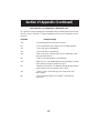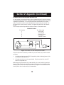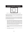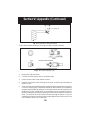
1
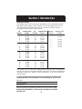
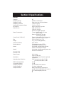
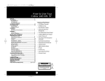
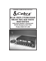
OPERATING INSTRUCTIONS FOR YOUR
40 CHANNEL
SOLID STATE CITIZENS BAND
SSB/AM TWO-WAY RADIO
BASE STATION
With Seven Weather Channels and
NOAA Emergency Alert Tone
Model 2010 GTL WX
How To Use Your
Cobra
®
SOLID STATE CITIZENS BAND
SSB/AM 2-WAY RADIO BASE STATION
Model 2010 GTL WX
Contents
Page
The CB Story .................................................................................... 1
Section I: Introduction ..................................................................... 2
Section II: Specifications ............................................................. 3, 4
Section III: Installation .................................................................... 5
Section IV: Operation ............................................................... 6 - 17
Control Functions ................................................................. 6, 7, 8
Indicator Functions ....................................................................... 9
Operating Procedure to Receive ................................................. 10
Operating Procedure to Transmit ................................................ 10
Operating Procedure to Receive Weather Band .................... 10, 11
Frequency Counter/LCD Digital Clock ........................................ 11
Receiving SSB Signals ........................................................... 13, 13
Section V: Maintenance and Adjustment ....................................... 14
FCC Warning .............................................................................. 14
Section VI: Appendix ......................................................... 15, 16, 17
Ten Code .................................................................................... 15
A Few Rules That Should Be Obeyed ......................................... 16
How Your CB Can Serve You ..................................................... 16
Use Channel 9 for Emergency Messages Only ............................ 17
Alternate Microphones and Installation .......................... 18, 19, 20
Warranty Service Instructions ..................................................... 21
Limited One Year Warranty ........................................................ 22
Cobra CB Radio Accessories .................................. Inside Back Cover
The CB Story
The Citizens Band lies between the shortwave broadcast and 10-meter Amateur radio
bands, and was established by law in 1949. The Class D two-way communications
service was opened in 1959. (CB also includes a Class A citizens band and Class C
remote control frequencies.)
FCC regulations permit only “transmissions” (one party to another) rather than
“broadcasts” (to a wide audience). Thus, advertising is not allowed on CB Channels
because that is “broadcasting.”
Replacement or substitution of transistors, regular diodes or other parts of
a unique nature, with parts other than those recommended by Cobra
Electronics, may cause violation of the technical regulations of Part 95 of
the FCC Rules, or violation of Type Acceptance requirements of Part 2 of the
Rules.
Citizens Band (CB) Radio operators are no longer required to obtain an FCC
license to operate their CB equipment or provide station identification.
Nevertheless, an operator of a CB radio station is still required to comply
with the communications act and with the rules of CB Radio Operation.
What Is Weather Radio?
NOAA WEATHER RADIO (NWR) is a service of the National Oceanic and Atmospheric Administration (NOAA), of the U.S. Department of Commerce. It provides
continuous, around-the-clock broadcasts of the latest weather information directly
from National Weather Service Offices. The broadcasts are tailored to the weatherinformation needs of people within the receiving area. For example, coastal and Great
Lakes' stations provide specialized weather information for area boaters, fishermen
and others engaged in marine activities, as well as general weather information for the
public-at-large. Three hundred eighty (380) NWR stations are in operation by the U.S.
Government in addition to several NWR stations that are maintained by private interest
groups.
Under a January 1975 White House policy statement, NOAA Weather Radio was
designated as the sole Government operated radio system to provide direct warnings
into private homes for both natural disasters and nuclear attack. The capability is to
supplement warnings by sirens and by commercial radio and television.
NWR Frequencies and Transmission Characteristics
NWR broadcasts have been allocated seven frequencies within the VHF radio
spectrum reserved for Government use. Assigned frequencies are:
162.400 MHz
162.425 MHz
162.450 MHz
162.475 MHz
162.500 MHz
1
162.525 MHz
162.550 MHz
Section I Introduction
FREQUENCY RANGE
The COBRA 2010 GTL WX transceiver represents one of the most advanced AM
base station radios used as a Class D station in the Citizens Radio Service. This
unit features advanced Phase Lock Loop (PLL) circuitry providing complete
coverage of all 40 channels as shown below.
CB
Channel
Channel Freq.
CB
Channel Freq.
in MHz
Channel
in MHz
1
2
3
4
5
26.965
26.975
26.985
27.005
27.015
21
22
23
24
25
27.215
27.225
27.255
27.235
27.245
6
7
8
9
10
27.025
27.035
27.055
27.065
27.075
26
27
28
29
30
27.265
27.275
27.285
27.295
27.305
11
12
13
14
15
27.085
27.105
27.115
27.125
27.135
31
32
33
34
35
27.315
27.325
27.335
27.345
27.355
16
17
18
19
20
27.155
27.165
27.175
27.185
27.205
36
37
38
39
40
27.365
27.375
27.385
27.395
27.405
Weather
Channel
Weather Freq.
in MHz
1
2
3
4
5
6
7
162.550
162.400
162.475
162.425
162.450
162.500
162.525
The COBRA 2010 GTL WX has a vastly superior receiver which includes noise
blanker circuitry and a switchable automatic noise limiter. The receiver also features
increased protection against cross modulation and strong adjacent
channel signals.
To obtain maximum performance please read carefully the descriptions and
operating instructions in this manual. Fill out below;keep for your records.
Serial No.
Date of Purchase
Dealer Name
Keep this manual for detailed information about your Cobra CB radio.
SAVE YOUR SALES RECEIPT, CARTON AND PACKING FOR POSSIBLE
FUTURE USE.
2
Section II Specifications
GENERAL
Channels
Frequency Range
Frequency Control
Frequency Tolerance
Operating Temperature Range
Microphone
Power Source
Power Consumption
Current Drain (13.8V DC)
Size
Weight
Antenna Conductor
Semiconductors
Meter 1
Meter 2
40.
26.965 to 27.405 MHz.
Phase Lock Loop (PLL) synthesizer.
±130 Hz Typical.
-30° C to + 50° C.
Plug-in type; 600Ω dynamic.
120V AC nominal.
13.8V DC nominal.
(Positive or negative ground).
Transmit: AM full mod., 65 watts.
SSB 70 watts.
Receive: Squelched, 30 watts.
Full audio, 40 watts.
Transmit: AM and SSB, 2.2A DC (nominal).
Receive: Full audio output, 1.1A DC
5”(H) x 15”(W) x 4 7/16”(D).
19 1/2 lbs. (Including speaker).
UHF, S0239.
12 integrated circuits, 3 FETs,
58 transistors, 79 diodes, 1 LCD.
Illuminated; indicates relative power
output, received signal strength.
Illuminated; indicates standing wave ratio
and level of modulation.
TRANSMITTER
Power Output
Modulation
Intermodulation Distortion
SSB Carrier Suppression
Unwanted Sideband
Frequency Response
Output Impedance
Output Indicators
AM, 4 watts.
SSB, 12 watts, PEP.
High-and low-level Class B, Amplitude
Modulation.
SSB: 3rd order, more than -25 dB.
5th order, more than -35 dB.
55 dB.
50 dB.
AM and SSB; 300 to 2500 Hz.
50 ohms, unbalanced
Meter shows relative RF output power
and SWR. RX/TX USB/LSB AM ANT. icons on
LCD, channel frequency and clock.
3
Section II Specifications (Cont.)
RECEIVER
Sensitivity
Selectivity
Image Rejection
IF Frequency
Adjacent-Channel Rejection
AM and SSB RF Gain Control
Automatic Gain Control (AGC)
Squelch
ANL
Noise Blanker
Voice Lock Range
Audio Output Power
Frequency Response
Built-in Speaker
External Speaker (Not Supplied)
SSB: 0.25 µV for 10dB (S+N)/N at greater
than 1/2-watt of audio output.
AM: 0.5 µV for 10 dB (S+N)/ at greater
than 1/2-watt of audio output.
AM: 6dB @ 3 KHz, 50 dB @ 9 KHz.
SSB: 6 dB @ 1.1 KHz, 60 dB @ 2.3 KHz.
More than 65 dB.
AM: 7.8 MHz 1st IF, 455 KHz 2nd IF.
SSB: 7.8 MHz.
60 dB AM & 70 dB SSB.
40 dB adjustable for optimum signal
reception.
Less than 10 dB change in audio output
for inputs from 10 to 100,000 microvolts.
Adjustable; threshold less than 0.25 µV.
Switchable.
RF type, effective on AM and SSB.
±1.5 KHz.
4 watts into 8 ohms.
300 to 2500 Hz.
8 ohms, round.
8 ohms; disables internal speaker
when connected.
CLOCK/COUNTER
Clock
Counter
24 hr. time.
Displays transmit and receive frequency.
WEATHER (WX) RECEIVER
Type
Modulation
Sensitivity
Frequency Range
Channels
Frequency Control
WX Emergency Warning
Audio Output Power
Single Conversion, Superhet 455Hz IF.
FM; ± 5 KHz Deviation.
Less than 1µV for 12dB Sinad.
162.400 to 162.550 MHz.
7; 25KHz Spacing.
Crystal.
Phase Lock Loop; 1050Hz.
4 watts.
(SPECIFICATIONS SUBJECT TO CHANGE WITHOUT NOTICE)
4
Section III Installation
LOCATION
Prior to beginning operation of the transceiver, a basic installation must be prepared.
Installation of the transceiver itself is a rather simple procedure.
In selecting the location for the unit, two basic factors must be considered:
1. Access to a 120V, 60 Hz power source.
2. The location must be convenient for running the antenna lead-in cable if outside
antenna installation is proposed.
BASE STATION ANTENNA
Since the maximum allowable power output of the transmitter is limited by the FCC,
the antenna is the most important factor affecting transmission distance. Only a
properly matched antenna system will allow maximum power transfer from the 50ohm transmission line to the radiating element.
The recommended method of antenna tuning is to use the built-in SWR meter to adjust
the antenna tuning for minimum reflected power on channel 21.
The radio may be used with any type of 50-ohm base station antenna. A ground plane
vertical antenna will provide the most uniform horizontal coverage. This type of
antenna is best suited for communication with a mobile unit. For point-to-point
operation where both stations are fixed, a directional beam will usually increase
communicating range since this type of antenna concentrates transmitted energy in
one direction. The beam antenna also allows the receiver to "listen" in only one
direction thus reducing interfering signals.
Antenna height is an important factor when maximum range is desired. Keep the
antenna clear of surrounding structures or foliage. FCC regulations for base station
antenna height are:
1. Omnidirectional antennas may not be higher than 60 feet above the ground when
using a tower, mast or pole, and no higher than 20 feet above an existing structure.
These are only general regulations applicable to most but not all parts of the nation.
Locations near airports and some military installations are subject to different rules;
therfore, it is best to contact your nearest Federal Communications Commission office
for information regarding your specific area.
MOBILE OPERATION/EMERGENCY POWER OPERATION
It is possible to operate the Cobra 2010 GTL WX from an external 13.8V DC power
supply for emergency conditions or from an automobile battery for mobile operation.
We recommend using a genuine Cobra DC power cord (not supplied). The DC power
cord can be purchased through your local dealer, or direct from Cobra. See CB radio
Accessories on the back page of this manual.
5
Section IV Operation
CONTROLS AND INDICATORS
There are eighteen controls, 2 meters, 1 LCD and 1 jack on the front panel of your
2010 GTL WX.
3
12
11
17
POWER
1
VOLUME
5
6
9 10 11
7 8
12
13
14
15
4
3
RF PWR
2
3
16
17
18
19
PHONE
0
20
16
1
3
SIGNAL
9
RX
TX
ANT
+30
AM / SSB
MIC
DYNAMIKE
2010 GTL
WX
4
5
SQUELCH
RF GAIN
USB
LSB
AM
HOUR
MOD
MIN
1.5
FREQ. CTR
BASE STA
TION WITH
WEATHER
VOICELOCK
15
100%
ANL
3
AM
CH 9
10
WX
13
CAL
SWR
NB
ALERT CLOCK
LSB
USB
2
0
TUNING
SWR CAL
SWR
CAL
MOD
MIN
MAX
COARSE
2
4
5
7
8
6
14
9
A. CONTROL FUNCTIONS
1. POWER SWITCH. Press in to turn on radio. Press in, again, and release to turn off
radio.
2. DYNAMIKE. Adjusts the microphone gain in the transmit mode. This controls the
gain to the extent that full talk power is available several inches away from the
microphone.
3. VOLUME. Turn clockwise to set the desired listening level.
4. SQUELCH . This control is used to cut off or eliminate receiver background noise
in the absence of an incoming signal. For maximum receiver sensitivity the control
should be adjusted only to the point where the receiver background noise or
ambient background noise is eliminated. Turn fully counterclockwise then slowly
clockwise until the receiver noise disappears. Any signal to be received must now
be slightly stronger than the average received noise. Further clockwise rotation
will increase the threshold level which a signal must overcome in order to be
heard. Only strong signals will be heard at a maximum clockwise setting.
5. RF GAIN CONTROL. Adjust as required to optimize the signal. This control is
used primarily to optimize reception in strong signal areas. Gain is reduced by
counterclockwise rotation of the control.
6
Section IV Operation (Continued)
6.
SWR CAL CONTROL . In order for you to achieve maximum radiated power and
the longest range, it is important that your antenna be in good condition, properly
adjusted and matched to your transceiver. The Built-in SWR (standing wave
ratio) meter lets you easily measure your antenna condition. To operate this
function, connect your antenna to the transceiver antenna output connector.
Select a channel near the middle of the band such as 21 or the channel you plan
to use most frequently. Turn the power on, set mode switch to AM, and set the
meter function switch to the CAL position. Press and hold the microphone pushto-talk button and using the SWR CAL control, adjust the meter to read the CAL
position indicated on the meter face. Then, without releasing the microphone
button, switch the meter function switch to the SWR position and read the SWR
indicated. The lower the figure, the better, with 1 being ideal. Generally
speaking, readings up to 3 are acceptable, but over 3 indicates that you are losing
radiated power and antenna adjustment may be advisable. This feature cannot
be used in Weather Mode.
7.
VOICE LOCK FINE/COURSE. Allows variation of the receiver operating frequencies above and below the assigned frequency. Although this control is
intended primarily to tune in SSB signals, it may also be used to optimize AM
signals. This feature cannot be used in the Weather Mode.
8.
MODE SWITCH (USB/LSB/AM). This switch selects AM (Amplitutde Modulation), USB (Upper Side Band) or LSB ( Lower Side Band) mode of operation. The
Mode selector switch changes the mode of operation of both the transmitter and
receiver simultaneously. This feature cannot be used in the Weather Mode.
9.
CHANNEL SELECTOR. In the CB Mode, this electronic selector selects any one
of the forty Citizens Band channels desired. The selected channel appears on the
LCD readout directly above the Channel Selector knob. In WX Mode, any one
of the 7 Weather Channels will be selected.
10. INSTANT CHANNEL 9 BUTTON. Use to activate Emergency Channel 9 instantly.
11. ANL SWITCH. In the ANL position, the noise reduction circuits of the Automatic
Noise Limiter are activated. This feature cannot be used in the Weather Mode.
12. NB SWITCH. When this switch is placed in the NB position the RF noise blanker
is activated. The RF noise blanker is very effective for repetitive impulse noise
such as ignition interference. This feature cannot be used in the Weather Mode.
13. WX/CB SWITCH. Selects the mode of operation. In the CB position, the WX
function is placed in Alert mode and the unit will transmit and receive on the
selected CB frequency. In the WX position, select one of 7 Weather Channels for
continous WX monitoring.
Note: Clock is displayed when in Weather Mode.
14. SWR/SWR CAL/MOD SELECTOR. In the MOD position, the MOD meter is
activated. When in the SWR or SWR CAL positions the SWR meter is activated.
This feature cannot be used in Weather Mode. In USB or LSB mode, the MOD
meter does not operate.
7
Section IV Operation (Continued)
15. PRESS-TO-TALK MICROPHONE. The receiver and transmitter are controlled by
the press-to-talk switch on the microphone. Press the switch and the transmitter
is activated; release switch to receive. When transmitting, hold the microphone
two inches from the mouth and speak clearly in a normal "voice." The radio is
supplied with a low-impedance 500-ohm dynamic desktop microphone. For
installation instructions on other microphones, see "ALTERNATE MICROPHONES
AND INSTALLATION.
16. HEAD PHONE JACK. For your individual listening with head phones.
17. EXTERNAL SPEAKER (Optional). The External Speaker Jack is used for remote
receiver monitoring. The external speaker should have 8-ohm impedance and be
rated to handle at least 4.0 watts. When the external speaker is plugged in, the
internal speaker is automatically disconnected.
•
WX ALERT TONE. If threatening weather is nearby, the National Weather
Service may broadcast a 10 second alert tone. This tone will be heard
through the CB, even if the CB/WX Switch is in the CB mode or the unit
is turned off (see NOTE below). This enables you to monitor CB frequencies and still be warned by the National Weather Service Emergency Alert.
When you hear the Alert, place the CB/WX switch in the WX position. You
will then be able to hear the Weather Warning Broadcast.
NOTE: If you are using the CB mode, remember to change the CB/WX
Switch from CB to WX every so often to make sure you are continually
tuned to the clearest weather band channel in case an alert is broadcast.
8
Section IV Operation (Continued)
POWER
6
5
3
7
1
2
100%
ANL
VOLUME
5
6
9 10 11
7 8
12
13
14
15
4
3
RF PWR
2
3
16
17
18
19
PHONE
0
20
1
3
SIGNAL
DYNAMIKE
2010 GTL
WX
4
5
9
+30
RX
TX
ANT
AM / SSB
MIC
4
SQUELCH
RF GAIN
USB
LSB
AM
HOUR
MOD
MIN
2
1.5
FREQ. CTR
BASE STA
TION WITH
WEATHER
ALERT CLOCK
VOICELOCK
LSB
USB
AM
3
0
CH 9
CAL
SWR
NB
WX
TUNING
SWR CAL
SWR
CAL
MOD
MIN
MAX
COARSE
8
INDICATOR FUNCTIONS
1.
MODULATION METER. Indicates the percent modulation (AM only).
NOTE
The SWR/SWR CAL/MOD switch must be in the
MOD position to read modulation.
2.
SWR METER. Measures the ratio of standing wave voltage of the antenna system.
Used to properly adjust the length of the antenna, and to monitor the quality of
the coaxial cable and all RF electrical connections. If there is any degradation
whatsoever in any of the above, due to humdidity, salt spray, vibration or
corrosion, the SWR meter reading will rise, therby indicating that a problem exists.
To calibrate, switch to the CAL position. Transmit by pressing the mic switch (AM
mode), and adjust the SWR/CAL control to the CAL mark on the meter. Then
switch to SWR position for the SWR measurement.
3.
S/RF METER. Indicates relative output power and incoming signal strength.
4.
CHANNEL INDICATOR. The selected channel appears on the LCD left of the
channel selector knob.
5.
RECEIVE INDICATOR (RX). Appears in LCD.
6.
TRANSMIT INDICATOR (TX). Appears in LCD.
7.
MODE INDICATOR (USB/LSB/AM). Mode appears in LCD when set by mode
selector.
8.
ANTENNA WARNING INDICATOR. Appears on the lower left corner of the LCD
if there is a serious degradation of the antenna system SWR due to humidity, salt
spray, vibration or corrosion.
9
Section IV Operation (Continued)
OPERATING PROCEDURE TO RECEIVE
1. Place the WX/CB Switch in the CB position.
2. Turn the set ON by pressing the POWER Switch.
3. Adjust the VOLUME for a comfortable listening level.
4. Set the Channel selector switch to the desired channel.
5. Set RF GAIN fully clockwise.
6. Set the Mode Selector to desired mode for LSB, AM or USB.
7. Adjust the VOICE LOCK control to clarify the SSB signals or to optimize AM
signals.
8. Listen to the background noise from the speaker. Turn the SQUELCH control
slowly clockwise, until the noise JUST disappears. (No signal should now be
present.) Leave the control at this setting. The SQUELCH is now properly adjusted.
The receiver will remain quiet until a signal is actually received. Do not advance
the control too far, or some of the weaker signals will not be heard.
OPERATING PROCEDURE TO TRANSMIT
1. Select the desired channel of transmission.
2. Set the DYNAMIKE control fully clockwise.
3. If the channel is clear, press the push-to-talk switch on the microphone and speak
in a normal voice.
The S-RF meter will indicate relative power output and the modulation meter will
indicate percentage of modulation as you speak into the microphone.
CAUTION
Be sure the antenna is properly connected to the radio before transmitting.
Prolonged transmitting without an antenna or a poorly matched antenna
could cause damage to the transmitter.
OPERATING PROCEDURE TO RECEIVE WEATHER BAND
1. Place WX/CB Switch in the WX position.
2. Turn the Weather Channel Selector (1-7) until you find the Weather
Channel with the clearest reception. Sometimes more than one channel
can be received depending on your location in the broadcast area; however, the closest broadcast to you will be the one with the clearest signal
(the least static or background noise).
10
Section IV Operation (Continued)
OPERATING PROCEDURE TO RECEIVE WEATHER BAND continued
3. If threatening weather is nearby, the National Weather Service may broadcast
a 10 second alert tone. This tone will be heard through the CB, even if the
WX/CB Switch is in the CB mode or the unit is turned off (see NOTE below).
This enables you to monitor CB frequencies and still be warned by the
National Weather Service Emergency Alert. When you hear the alert, place
the WX/CB Switch in the WX position. You will then be able to hear the
Weather Warning Broadcast.
NOTE: If you are using the CB Mode, remember to change the WX/CB Switch
from CB to WX every so often to make sure you are continually tuned to the
clearest weather band channel in case an alert is broadcast.
FREQUENCY COUNTER/LCD DIGITAL CLOCK
1. Located on the right side of the LCD is the Counter/Clock Indicator.
2. For proper procedure to set your LCD Clock, there are the following features:
TIME SET: 2 switches (used to set time).
COUNTER/CLOCK: 1 switch (used to select display).
TO SET TIME
1. Press FREQ. CTR./CLOCK Switch to select the clock.
2. HOUR SWITCH: Press this switch to get correct hour setting.
3. MINUTE SWITCH: Press this switch to get correct minutes setting.
NOTE: the 2010 GTL WX uses a 24-hour clock display (no a.m. or p.m. indicated). Example:
Display Reads
01:00
12:00
18:00
24:00
Time Is:
1:00 a.m.
12:00 noon
6:00 p.m.
12:00 midnight
FREQ. CTR./CLOCK:
On power up, the display shows
channel number and frequency being
received. Pressing thr FREQ. CTR./
CLOCK button will select the Clock.
Clock mode only is displayed in the
WX (weather) mode. When switching
out of WX mode, the display will
continue to show the clock until the
FREQ. CTR./CLOCK button is pressed
again.
11
Cobra
®
2010 GTL WX
HOUR
RX
LSB
:
MIN
FREQ. CTR.
CLOCK
Display in RX mode with Clock showing.
Section IV Operation (Continued)
RECEIVING SSB SIGNALS
There are three types of signals presently used for communications in the Citizens
Band: AM, USB, and LSB. When the MODE switch on your unit is placed in the AM
position, only standard double-sideband, full carrier signals will be detected. An SSB
signal may be recognized while in the AM mode by its characteristic “Donald Duck”
sound and the inability of the AM detector to produce an intelligible output. The USB
and LSB modes will detect upper sideband and lower sideband respectively, and
standard AM signals.
SSB reception differs from standard AM reception in that SSB receiver does not require
a carrier or opposite sideband to produce an intelligible signal. A single-sideband
transmitted signal consists only of the upper or the lower sideband and no carrier is
transmitted. The elimination of the carrier from the AM signal helps to eliminate the
biggest cause of whistles and tones heard on channels which make even moderately
strong AM signals unreadable. Also, SSB takes only half of an AM channel, therefore two
SSB conversations will fit into each channel, expanding the 40 AM channels to 80 SSB
channels. The reduction in channel space required also helps in the receiver because
only half of the noise and interference can be received with 100% of the SSB signal.
An SSB signal may be received only when the listening receiver is functioning in the
same mode. In other words, an upper sideband signal (USB) may be made intelligible
only if the receiver is functioning in the USB position.
If a lower sideband (LSB) signal is heard when the receiver is in the USB mode, no
amount of tuning will make the signal intelligible. The reason for this may be
understood if you consider that when the modulation is applied to the transmitter’s
microphone in the USB mode, the transmitter’s output frequency is increased whereas
in the LSB mode the transmitter’s output frequency is decreased. The result in listening
to the receiver is that when the MODE switch is in the proper position (either USB or
LSB), a true reproduction of single tone of modulation will result, and if the tone is
increased in frequency (such as a low-pitched whistle or a high-pitched whistle) you
will hear the increase in the output tone of the receiver. If the incorrect mode is selected,
an increase in tone of a whistle applied to the transmitter will cause a decrease in the
resultant tone from the receiver.
Thus when a voice is used in place of a whistle or tone, in the proper listening mode
the voice will be received correctly whereas in the incorrect mode, the voice will be
translated backwards and cannot be made intelligible by the voice lock control. When
listening to an AM transmission, a correct sideband is heard in either mode since both
upper and lower sideband are received.
12
Section IV Operation (Continued)
RECEIVING SSB SIGNALS continued
Once the desired SSB mode has been selected, frequency adjustment may be necessary
in order to make the incoming signal intelligible, the VOICE LOCK control allows the
operator to vary frequency above and below the exact-center frequency of the received
signal. If the sound of the incoming signal is high or low pitched, adjust the operation
of the VOICE LOCK. Consider it as performing the same function as a phonograph
speed control. When the speed is set too high, voices will be high-pitched and if set
too low, voices will be low-pitched. Also, there is only one correct speed that will make
a particular record produce the same sound that was recorded. If the record is played
on a turntable that rotates in the wrong direction (opposite sideband) no amount of
speed control (VOICE LOCK) will produce an intelligible sound.
An AM signal received while listening in one of the SSB modes will produce a steady
tone (carrier) in addition to the intelligence, unless the SSB receiver is tuned to exactly
the same frequency by the VOICE LOCK control. For simplicity it is recommended that
the AM modes be used to listen to AM signals.
13
Section V Maintenance and Adjustment
The COBRA 2010 GTL WX transceiver is specifically designed for the environment
encountered in base station installations. The use of all solid state circuitry and its light
weight result in high reliability. Should a failure occur, however, replace parts only
with identical parts. Do not substitute. Refer to the schematic diagram and parts list.
NOTE
If the performance described in the OPERATION and MAINTENANCE
AND ADJUSTMENT sections is not obtained, review the operating instructions to insure that proper procedures were followed. If a problem still
exists, refer to WARRANTY SERVICE INSTRUCTIONS elsewhere in
this manual.
FCC WARNING
All transmitter adjustments other than those provided on front panel
by the manufacturer must be made by or under the supervision of the
holder of an FCC-issued general radio-telephone operator’s license.
14
Section VI Appendix
Citizens Band operators have largely adopted the “10-code” for standard questions and
answers. Its use permits faster communications and better understanding in noisy
areas. The following table lists some of the more common codes and their meanings.
10 CODE
Code Meaning
10-1
Receiving poorly
10-2
Receiving well
10-3
Stop transmitting
10-4
OK, message received
10-5
Relay message
10-6
Busy, stand by
10-7
Out of service, leaving air
10-8
In service, subject to call
10-9
Repeat message
10-10 Transmission completed,
standing by
10-11 Talking too rapidly
10-12 Visitors present
10-13 Advise Weather/Road conditions
10-16 Make pick up at
10-17 Urgent business
10-18 Anything for us?
10-19 Nothing for you, return to base
10-20 My location is
10-21 Call by telephone
10-22 Report in person to
10-23 Stand by
10-24 Completed last assignment
10-25 Can you contact
10-26 Disregard last information
10-27 I am moving to channel
10-28 Identify your station
10-29 Time is up for contact
10-30 Does not conform to FCC rules
10-32 I will give you a radio check
10-33 EMERGENCY TRAFFIC
10-34 Trouble at this station
10-35 Confidential information
10-36 Correct time is
15
Code Meaning
10-37 Wrecker needed at
10-38 Ambulance needed at
10-39 Your message delivered
10-41 Please turn to channel
10-42 Traffic accident at
10-43 Traffic Tie up at
10-44 I have a message for you
10-45 All units within range
please report
10-50 Break channel
10-60 What is the next message
number?
10-62 Unable to copy, use
phone
10-63 Net directed to
10-64 Net clear
10-65 Awaiting your next
message/assignment
10-67 All units comply
10-70 Fire at
10-71 Proceed with transmission
in sequence
10-77 Negative contact
10-81 Reserve hotel room for
10-82 Reserve room for
10-84 My telephone number is
10-85 My address is
10-91 Talk closer to mike
10-93 Check my frequency on
this channel
10-94 Please give me a long
count
10-99 Mission completed, all
units secure
10-200 Police needed at
Section VI Appendix (Continued)
A FEW RULES THAT SHOULD BE OBEYED
1.
You are not allowed to carry on a conversation with another station for more than
five minutes at a time without taking a one-minute break, to give others a chance
to use the channel.
2.
You are not allowed to blast others off the air by over-powering them with
illegally amplified transmitter power, or illegally high antennas.
3.
You can’t use the CB to promote illegal activities.
4.
You are not allowed to use profanity.
5.
You may not play music in your CB.
6.
You may not use your CB to sell merchandise or professional service.
HOW YOUR CB CAN SERVE YOU
•
•
•
•
•
•
•
•
•
Warn of traffic tie ups ahead.
Provide weather and road information.
Provide help fast in event of emergency or breakdown.
Suggest good spots to eat and sleep.
Make long trips more interesting, and help keep you awake.
Provide direct contact with your office or home.
Make friends for you as you travel.
Provide “local information” to find you destination.
Help law enforcement officers by reporting drunk and reckless drivers.
Colonel Samuel S. Smith of the Missouri Highway Patrol called the number of drunken
drivers, wrong-way drivers and speeders reported by CBers as “amazing.” He said,
that even the “Smokey Bear” warnings don’t shake their beliefs that “the potential
benefits of CB radio to law enforcement are so great that they far outweigh the
disadvantages.” In regards to CB radar warnings to other CBers, Colonel Smith said
cheerfully that “We’ve overheard warnings being relayed to truckers long after our
operations have been discontinued...so we actually receive a residual benefit from
these warnings.”
16
Section VI Appendix (Continued)
USE CHANNEL 9 FOR EMERGENCY MESSAGES ONLY
FCC gives the following examples of permitted and prohibited types of communications for use on Channel 9. These are guidelines and are not intended to be allinclusive.
Permitted
Example Message
Yes
”A tornado sighted six miles north of town.”
No
”This is observation post number 10. No tornado sighted.”
Yes
”I am out of gas on Interstate 95.”
No
”I am out of gas in my driveway.”
Yes
There is a four-car collision at Exit 10 on the Beltway, send
police and ambulance.”
No
”Traffic is moving smoothly on the Beltway.”
Yes
”Base to Unit 1, the Weather Bureau has just issued a thunder
storm warning. Bring the sailboat into port.”
No
”Attention all motorists. The Weather Bureau advises that the
snow tomorrow will accumulate 4 to 6 inches.”
Yes
“There is a fire in the building on the corner of 6th and
Main Streets.”
No
“This is Halloween patrol unit number 3. Everything is
quiet here.“
17
Section VI
IV Appendix
Operation(Continued)
(Continued)
ALTERNATE MICROPHONES AND INSTALLATION
For best results, the user should select a low-impedance dynamic type microphone
or a transistorized microphone. Transistorized type microphones have a low output
impedance characteristic. The microphones must be provided with a five-lead
cable. The audio conductor and its shielded lead comprise two of the leads. The
third lead is for receive control, the forth is for grounding and fifth is for transmit
control.
The microphone should provide the functions shown in schematic below.
5 WIRE MIC CABLE
Pin Number
Mic Cable Lead
1
2
3
4
5
Audio Lead
Audio Shield
Receive Control
Grounding
Transmit Control
Fig. 1. Cobra 2010 GTL WX microphone schematic.
If the microphone to be used is provided with pre-cut leads, they must be revised
as follows.
1.
Cut leads so that they extend 7/16” beyond the plastic insulating jacket of the
microphone cable (see Fig. 2.)
2.
All leads should be cut to the same length. Strip the ends of each wire 1/8”
and tin the exposed wire.
Before beginning the actual wiring, read carefully, the circuit and wiring information provided with the microphone you select. Use the minimum lead required in
soldering the connections. Keep the exposed wire lengths to a minimum to avoid
shorting when the microphone plug is reassembled.
18
Section VI Appendix (Continued)
Fig. 4. Microphone plug pin numbers viewed from rear of pin receptacle.
Be sure that the housing and the knurled ring of Fig. 3 are pushed back onto the
microphone cable before starting to solder. If the washer is not captive to the pin
receptacle body, make sure that it is placed on the threaded portion of the pin
receptacle body before soldering.
If the microphone jack is used to hold the pin receptacle during soldering operation,
best results are obtained when the connections to pins 1 and 3 are made first and then
the connections to pins 2, 4 and 5. Use a minimum amount of solder and be careful
to prevent excessive solder accumulation on pins, which could cause a short between
the pin and the microphone plug housing.
6.
When all soldering connections to the pins of the microphone are complete,
push the knurled ring and the housing forward and screw the housing onto the
threaded portion of the pin receptacle body. Note the location of the screw
clearance hole in the plug housing with respect to the threaded hole in the pin
receptacle body. When the housing is completely threaded into the pin
receptacle body, a final fraction of a turn either clockwise or counterclockwise
may be required to align the screw hole with the threaded hole in the pin
receptacle body. When these are aligned, the retaining screw is then screwed
into place to secure the housing to the pin receptacle body.
7.
The two cable clamp retainer screws should now be tightened to secure the
housing to the microphone cord. If the cutting directions have been carefully
followed, the cable clamp should secure to the insulation jacket of the microphone cable.
8.
Upon completion of the microphone plug wiring, connect and secure the
microphone plug in the transceiver.
19
Section VI Appendix (Continued)
Fig. 2. Microphone Cable Preparation
To wire the microphone cable to the plug provided, proceed as follows.
Fig. 3. Microphone plug wiring.
1.
Remove the retaining screw.
2.
Unscrew the housing from the pin receptacle body.
3.
Loosen the two cable clamp retainer screws.
4.
Feed the microphone cable through the housing, knurled ring and washer as
shown Fig. 3B.
5.
The wires must now be soldered to the pins as indicated in the above wiring tables.
If a vise or clamping tool is available it should be used to hold the pin receptacle
body during the soldering operation, so that both hands are free to perform the
soldering. If a vise or clamping tool is not available, the pin receptacle body can
be held in a stationary position by inserting it into the microphone jack on the front
panel. The numbers of the pins of the microphone plug are shown in Fig 4, as
viewed from the back of the plug. Before soldering the wire to the pins, pre-tin the
wire receptacle of each pin of the plug.
20
If You Need Service
If You Think You Need Service, Call 773-889-3087
You may be asked to send your unit to the Cobra factory. It will be necessary to
furnish the following, in order to have the product serviced and returned.
1. For Warranty Repair, include some form of proof-of-purchase, such as a mechanical
reproduction or carbon or a sales receipt. If you send the original receipt it cannot be
returned.
2. Send the entire product. Must include CB unit and microphone.
3. Enclose a description of what is happening with the unit. Include a typed or clearly
printed name and address of where the unit is to be returned.
4. Pack unit securely to prevent damage in transit. If possible, use the original packing
material.
5. Ship prepaid and insured by way of a traceable carrier ( to avoid loss in transit) such
as United Parcel Service (UPS), Roadway Parcel Service (RPS) or First Class Insured
Mail to Cobra Factory Service, Cobra Electronics Corporation, 6500 W. Cortland
St., Chicago, IL 60707. Cobra is not responsible for units not received if package has
not been properly insured.
6. If the unit is in warranty, upon receipt of your unit it will either be repaired or exchanged
depending on the model. Please allow approximately 3 to 4 weeks before contacting
us for status. If the unit is out of warranty a letter will automatically be sent informing
you of the repair charge or replacement charge. If you have any questions, please call
773-889-3087 for assistance.
For technical assistance, please call our Automated Help Desk
which can assist you by answering the most frequently asked
questions about Cobra products.
(773) 889-3087
24 hours a day, 7 days a week.
A Consumer Service Representative
can be reached through this same number
8:00 am - 8:00 pm, Monday through Friday, CST.
Technical assistance is also available on-line in the
Frequently Asked Question (FAQ) section at
www.cobraelec.com or by e-mail to [email protected]
21
WARRANTY
Limited Two Year Warranty
COBRA ELECTRONICS CORPORATION warrants that its COBRA citizens band (CB)
radio, and the component parts thereof, will be free of defects in workmanship and
materials for period of two (2) year from the date of first consumer purchase. This warranty
may be enforced by the first consumer purchaser, provided that the product is utilized
within the U.S.A.
COBRA will, without charge, repair or replace, at its option, defective citizens band (CB)
products or component parts upon delivery to the COBRA factory Service Department,
accompanied by proof of the date of first consumer purchase, such as a duplicated copy
of a sales receipt.
You must pay any initial shipping charges required to ship the product for warranty service.
The return charges will be at Cobra’s expense, if the product is repaired or replaced under
warranty. For further details concerning procedures for obtaining service, see the “If You
Need Service” section of the Owner’s Manual.
Exclusions: This limited warranty does not apply; 1) to any product damaged by accident;
2) in the event of misuse or abuse of the product or as a result of unauthorized alterations
or repairs; 3) if the serial number has been altered, defaced or removed; 4) if the owner
of the product resides outside the U.S.A.
All implied warranties, including warranties of merchantability and fitness for a
particular purpose are limited in duration to the length of this warranty.
COBRA shall not be liable for any incidental, consequential or other damages; including,
without limitation, damages resulting from loss of use or cost of installation.
Some states do not allow limitations on how long an implied warranty lasts and/or do
not allow the exclusion or limitation of incidental or consequential damages, so the
above limitations may not apply to you.
This limited warranty gives you specific legal rights, and you may also have other rights
which vary from state to state.
Cobra Electronics Corporation,
6500 W. Cortland Street, Chicago, IL 60707
22
FOLD THIS FLAP OVER BOTTOM AND TAPE IT DOWN AND SIDES TO CLOSE
COBRA CB RADIO ACCESSORIES
Cost Ea. X Qty. = Amount
AT-55 Cellular-Style Glass-Mount Antenna
for 2010 GTL WX
AT-55
$24.95
CA-72 BASE STATION MICROPHONE with
5-pin connector for 2010 GTL WX
CA-72
$53.95
CA-78, MOBILE POWER MICROPHONE
Amplified Power Microphone with 5-pin connector
for 2010 GTL WX
CA-78
$39.95
ATW-400 DUAL BAND ANTENNA, Magnetic
mount with 15' RG58U Cable and PL-259 connector ATW-400
$39.95
ATW-480 DUAL BAND ANTENNA Truck mirror
mount with 1.2 meter 3/8" fiberglass whip,
weather tunable
ATW-480
$29.95
ATW-500 DUAL BAND ANTENNA 48" whip, magnet
mount with 16’ 8240 cable & PL-259 connector
ATW-500
$49.95
ATW-1000 DUAL BAND ANTENNA Magnet mount
with16' 8240 cable and PL-259 connector
ATW-1000
$89.95
ATW-2000 DUAL BAND ANTENNA Truck mirror
mount, 48" stainless steel whip, weather tunable
ATW-2000
$69.95
DC POWER CORD for 2010 GTL WX
PC-2010
$5.00
93 ATW INDOOR DUAL BAND (CB/WEATHER)
BASE STATION ANTENNA with 15 ft. coaxial cable ATW-93
★★
Illinois residents add 7%
Cook County, IL residents additional .75% (7.75% total)
★★
Chicago, IL residents additional 1% (8.75% total)
★★
Indiana residents add 5%
★★
Michigan residents add 6 %
★★
Ohio residents add 6%
★★
Wisconsin residents add appropriate %
★★
$44.95
Amount
(Tax if applicable ★★)
Shipping / handling
Total★★
Make check or money order (no stamps) payable to :
Cobra Accessories Dept.
6500 W. Cortland St., Chicago, IL 60707
or call 773-889-3087 for credit card orders.
Please print clearly—this is shipping label.
Name
Address (Not P.O. Box)
City
State
THIS LINE SECOND
Part No.
FOLD ALONG
CUT ALONG
FOLD ALONG
DOTTED LINE
THIS LINE FIRST
Description
Zip
Allow 4 to 6 weeks delivery. Offer valid in Continental U.S. only.
$3.50
FOLD HERE TO MAKE SELF MAILER
PLACE
STAMP
HERE
Cobra
®
Cobra Electronics Corporation
6500 W. Cortland Street
Chicago, IL 60707
PRINTED IN MALAYSIA
©COBRA ELECTRONICS CORP. 1996
480-114-P-001