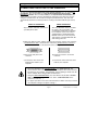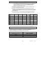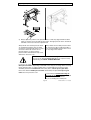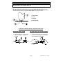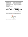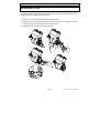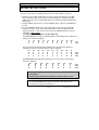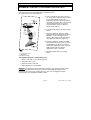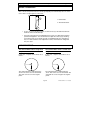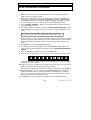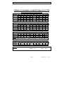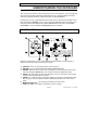
1
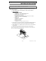
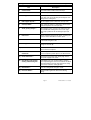
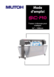
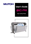
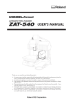
SC CUTTING PLOTTERS OPERATION INSTRUCTIONS MUTOH EUROPE N.V. Part n°: AP-75026 Rev. 1.0 - 11/01/00 Operation Instructions SC Cutting Plotters AP-75026 Rev 1.0 - 11/01/00 Operation Instructions SC Cutting Plotters COPYRIGHT NOTICE COPYRIGHT 2000 Mutoh Europe N.V. All rights reserved. This document may not be reproduced by any means, in whole or in part, without written permission of the copyright owner. This document is furnished to support the MUTOH SC Series cutting plotters. In consideration of the furnishing of the information contained in this document, the party to whom it is given assumes its custody and control and agrees to the following: 1. The information herein contained is given in confidence, and any part thereof shall not be copied or reproduced without written consent of Mutoh Europe N.V. 2. This document or the contents herein under no circumstances, shall be used in the manufacture or reproduction of the article shown and the delivery of this document shall not constitute any right or license to do so. FCC WARNING This equipment complies with the requirements for a class A computing device in the FCC rules, part 15, subpart J. Operation of this device in a residential area may interfere with television reception or operation of utilities. Cutters generate weak radio signals and may interfere with television reception and utilities. If the cutter does interfere with radio or TV reception, try the following: • Change the direction of your radio and TV reception antenna or feeder. • Change the direction of the cutter. • Move either the cutter or the receiving antenna so that there is more distance between them. • Be sure the cutter and the receiving antenna are on separate power lines. AP-75026 Rev 1.0 - 11/01/00 Operation Instructions SC Cutting Plotters AP-75026 Rev 1.0 - 11/01/00 Operation Instructions SC Cutting Plotters Congratulations with your new MUTOH cutting plotter ! We are happy to find you joining the ever rapidly growing family of MUTOH computer peripherals users. By purchasing an SC series cutter, you have become the owner of one of the most versatile single-tool cutters in the market. It is fast, reliable, of the highest quality and has been assembled with the application of the most stringent quality checks. But even more important, it is easy to use, as the following guide will show you. Hereafter you will find all information necessary to set-up your SC cutting plotter in a trice. ENJOY ! AP-75026 Rev 1.0 - 11/01/00 Operation Instructions SC Cutting Plotters AP-75026 Rev 1.0 - 11/01/00 Operation Instructions SC Cutting Plotters TABLE OF CONTENTS: SC CUTTING PLOTTERS OPERATION INSTRUCTIONS Setting up the cutter ....................................................................................1 Preparing the cutting environment ...............................................................................1 Unpacking your SC cutter ............................................................................................2 What’s in the box ?.......................................................................................................2 Getting to know the cutter parts ...................................................................................3 Connecting the cutter to the computer .........................................................................5 Connecting the power cable.........................................................................................6 Communication Settings...............................................................................................6 Changing the set-up language of your cutter ...............................................................7 Preparing for a job .......................................................................................9 Loading media..............................................................................................................9 Adjusting the knife depth ............................................................................................12 Installing a tool ...........................................................................................................14 Tool presets / Tooltype selection................................................................................15 General procedure to change settings on the cutter ..................................................16 Setting the tool force ..................................................................................................17 Setting the tool speed.................................................................................................18 Acceleration Selection................................................................................................18 Alignment feature to perform contour cuts .................................................................19 Offset principle ...........................................................................................................20 Offset effect................................................................................................................20 Offset adjustment procedure ......................................................................................21 Performing a test cut ..................................................................................................23 Understanding the keyboard ....................................................................27 Function keys .............................................................................................................27 Control panel overview...............................................................................................28 AP-75026 Rev 1.0 - 11/01/00 Operation Instructions SC Cutting Plotters AP-75026 Rev 1.0 - 11/01/00 Setting up the cutter Operation Instructions SC Cutting Plotters SETTING UP THE CUTTER PREPARING THE CUTTING ENVIRONMENT The location where you set up your equipment is very important. Please see to it that it meets following conditions : ♦ Power supply of 100 to 120 VAC 50/60 Hz or 200 to 240 VAC 50/60 Hz. ♦ Ambient Conditions : • Operating environment - Temperature : 5° C to 40° C ( 41° F to 104° F ) - Humidity : 35% - 75% non-condensing. • Recommended environment - Temperature : Room temperature 16°C to 32°C ( 61° F to 90° F ) - Humidity : 50% to 65%, non-condensing. • Variation rate - Temperature : 2° C per hour. - Humidity : 5% per hour. • Storage environment - Temperature : 0° C to 50° C ( 32° F to 122° F) ♦ Please protect your cutter from moisture, dust, draughts and direct sunlight. It is best to keep your machine away from open windows and air-conditioners. ♦ See to it that there is an adequate space around the cutter so that ventilation is not obstructed. ♦ Avoid unnecessary vibrations and set up your cutter on a level surface. When selecting a place for your cutter, leave at least 90 cm in front and 90 cm at the rear, as shown in the illustration below. Page 1 AP-75026 Rev 1.0 - 11/01/00 Setting up the cutter Operation Instructions SC Cutting Plotters UNPACKING YOUR SC CUTTER • • • • When unpacking the cutter, check whether all parts described in the parts list are included in the box. Consult your dealer if anything seems to be missing. Lifting the machine out of the box should be done by two people. Protect the plotter from firm shocks. Do not dismantle the unit To unpack the cutter: 1. 2. 3. 4. 5. Lift the cutter unit out of the box and put it on a flat and stable surface. Take out the accessories box. Remove all plastic wrapping materials. Remove the pieces of foam, protecting the tool head during transportation. If you had your cutter delivered with a stand, please refer to the instructions for mounting the stand. WHAT’S IN THE BOX ? What’s in the box - SC-? • SC plotter unit with roll support system, 2 conveyor rolls and small guiding flanges • Cutting plotter stand (optional for SC-650) • Mutoh SC Series User guide • Knife holder with pre-mounted cutting blade • Set of 2 spare cutting blades + spring • Set of 2 water-based fibre tip pens • Spare cutting mat • Power Cord • RS-232 interface cable Page 2 AP-75026 Rev 1.0 - 11/01/00 Setting up the cutter Operation Instructions SC Cutting Plotters GETTING TO KNOW THE CUTTER PARTS Page 3 AP-75026 Rev 1.0 - 11/01/00 Setting up the cutter Operation Instructions SC Cutting Plotters Part Description 1) Control Panel : Panel with indicator LEDs and control keys. 2) Power Switch : Switches the plotter ON or OFF. 3) Carriage Cover : For safety reasons, the cutter will not work with the cover open. The cover will also prevent objects from falling into the cutting zone. 4) Roll Support System : The roll support system carries the conveyor rolls. 5) Conveyor Rolls : When using roll media for cutting jobs, put the roll of media on top of the two conveyor rolls. 6) Small guiding Flanges : These flanges on the conveyor rolls will prevent the roll of media from shifting to the left or to the right when vinyl is pulled off the roll during the pre-feed cycle. 7) Hold Lever : Raises and lowers the pressure rollers. Lowering the pressure rollers will hold the media in place. 8) Platen & Grid Cover : Supports the cutting media and guides the movement of the media along the x-axis. 9) Cutting Mat : Provides a firm cutting surface and minimises damage to the knife tip. 10) Serial Interface Connector : RS-232 serial interface connector to connect the cutter to the host computer. 11) Parallel Interface Connector : Centronics parallel connector to connect the cutter to the host computer’s printer port for fast data transfer. 12) Power Connector : Connector for the power cord, which plugs into the main power supply of the cutter. 13) Dual Action Tool head for Cutting and Sheeting Off: All available tools such as knife holders, drawing pens and painting pens can be secured into the head using the locking screw. The tool head moves along the Y-axis to locate the cutting position. 14) Drive Rollers : Move the cutting media along the X-axis. 15) Pressure Rollers : Hold the media against the drive rollers during cutting. Page 4 AP-75026 Rev 1.0 - 11/01/00 Setting up the cutter Operation Instructions SC Cutting Plotters CONNECTING THE CUTTER TO THE COMPUTER To make the connection between the cutter and the computer, you are offered two possibilities. The first possibility is a high-speed unidirectional 8-bit parallel Centronics interface. The second possibility is a 2-way RS-232C serial interface. Of course, it is also possible to connect two different computers to the cutter, the first one using the serial interface, the second one using the parallel interface. The cutter will automatically determine on which port data is coming in and will handle the jobs one by one. SERIAL INTERFACE PARALLEL INTERFACE All you need to make this connection is a parallel printer cable. The serial RS-232C interface enables the cutter to be connected to and controlled by an RS-232C compatible host computer system. The cutter is equipped with a standard RS-232C DB-25P connector on the rear panel and requires a standard RS-232C dB25S mating connector. a) Make sure both the cutter and the computer are turned off. Connect one end of the parallel interface cable / serial interface cable to the parallel interface connector / serial interface connector at the back side of the cutting plotter. b) Secure the lock pins to the connector. b) Fasten the screws to secure the connector. c) Connect the other end of the parallel printer cable to your computer. c) Connect the other end of the serial cable to your computer. • Please be advised that the parallel interface only works one-way. This means that the cutter can receive data from the computer but cannot send any information to the computer. Consequently, software polling for media size will not be available when using parallel communication. • Using the serial communication, your cutter will not only be able to receive data from the computer, but will also be able to send information to the computer (media size, ...). • For proper operation of the serial communication, it will be necessary to match the computer settings to the plotter settings ! Page 5 AP-75026 Rev 1.0 - 11/01/00 Setting up the cutter Operation Instructions SC Cutting Plotters CONNECTING THE POWER CABLE 1. Make sure the plotter’s power switch is turned OFF. 2. Plug the plotter-end of the power cable into the connector at the back of the plotter. 3. Plug the other end of the power cable into an electrical outlet of the correct voltage and with a proper grounding. COMMUNICATION SETTINGS In order for your plotter to be able to communicate well with your host computer, the communication settings on both machines have to match exactly. Please refer to the manual of your software to determine which communication settings will be used by your software. Your cutter is able to be set up to use any settings necessary. You can proceed in two ways: • You can check which of the 5 possible defaults matches your software and enable this particular default setting. • You can set all communication parameters yourself. In this case, for communication, select USER DEFINED. To do this proceed as follows: 1) Install a PEN in the tool head. 2) Load an A3-size ( B-Size) sheet of paper or larger into the cutter (short side first). 3) Switch the cutter to OFF-LINE by pressing the ONLINE button. 4) Now you can enter the MENU-MODE by pressing: ENTER & À (SETUP). 5) The cutter now plots a MENU-SELECTION LINE (example below). MENU: xx.xx: 1 2 3 4 5 6 7 8 9 10 11 12 13 14 15 16 17 18 19 20 21 22 23 24 25 26 27 28 29 30 31 32 SHOW This menu selection line will give you direct access to : • 32 different cutter settings. • a SHOW function which will plot the actual settings on an A3-size (B-size) sheet. 6) After having plotted this line, the user can park the tool head above any of the options using the or JOG keys. ½ ¾ 7) When ENTER is pressed, there are two possibilities : • When ENTER is pressed with the head above SHOW , the current settings are plotted. Afterwards, the tool head is returned to the MENU-SELECTIONLINE. Page 6 AP-75026 Rev 1.0 - 11/01/00 Setting up the cutter Operation Instructions SC Cutting Plotters • When ENTER is pressed with the head above any of the other options, only that line is plotted with its different parameter possibilities. After this, the head will be parked above the current setting. The communication settings can be found in lines 8 to 16. ¿ À With the ½ & ¾ JOG-keys, the head can be positioned above the desired 8) With the & JOG-keys you can return to the MENU-SELECTION LINE leaving the original setting unchanged. 9) setting, after which the ENTER key needs to be pressed to save the new setting into memory. When ENTER has been pressed, the head returns to the MENUSELECTION-LINE. 10) The cutter will return to its normal operation mode by putting the media hold lever in the “up” position and removing the SET-UP SHEET from the cutter. 8. Communication DEFAULT 1 DEFAULT 2 DEFAULT 3 DEFAULT 4 DEFAULT 5 USER DEFINED 9. BAUDRATE 9600 9600 9600 9600 9600 Adjustable 10. DATABITS 7 8 7 8 8 Adjustable 11. PARITY EVEN NONE EVEN NONE EVEN Adjustable 12. STOPBITS 1 1 1 1 2 Adjustable 13. SOFTWARE HANDSHAKE OFF OFF Xon/Xoff Xon/Xoff OFF Adjustable 14. DTR-Pin ON ON OFF OFF ON Adjustable 15. CTS-Pin OFF OFF OFF OFF OFF Adjustable 16. RTS-Pin ON ON ON ON ON Adjustable The factory default settings are shown in Bold-face. CHANGING THE SET-UP LANGUAGE OF YOUR CUTTER It is possible to change the user language of your cutter, thus changing the set-up sheet language. Changing the set-up language can be done by pressing two keys simultaneously during power-up. See table below for an overview. LANGUAGE KEY COMBINATION American (dimensions in inches) German French English (dimensions in metric units) Japanese ENTER + JOG-DOWN ENTER + JOG-UP ENTER + JOG-RIGHT ENTER + JOG-LEFT ENTER + ONLINE Page 7 AP-75026 Rev 1.0 - 11/01/00 Setting up the cutter Operation Instructions SC Cutting Plotters Page 8 AP-75026 Rev 1.0 - 11/01/00 Preparing for a job Operation Instructions SC Cutting Plotters PREPARING FOR A JOB This section covers the tasks you should perform as you prepare for running a job. • • • • • • • • • Loading the material Adjusting the knife depth Installing a tool Selecting a tool on the control panel Setting the force, the speed and the acceleration Alignment feature Changing the settings Offset principle, effect and offset adjustment procedure Performing a test cut LOADING MEDIA When loading media into the cutter, it is necessary to clearly distinguish two situations. The first situation is when you are using cut-sheet media. The second situation is when you are using a roll of media. LOADING CUT SHEET MEDIA LOADING ROLL MEDIA 1) Close the safety cover (1), put the pressure rollers in the “up” position using the media hold lever and turn the power switch ON. The cutter will perform its initialisation routine and move the tool head to the rightmost position. 2) Open the protective cover (1) and insert 2) the media into the cutter. On the aluminium extrusion, marker lines have been affixed for alignment purposes. It is best to position the media so that half of it hangs in front and half of it hangs at the back of the cutter. Page 9 Position the roll of media onto the conveyor rolls. Open the protective cover and pull the media through to be able to choose the best possible position for the pressure rollers. AP-75026 Rev 1.0 - 11/01/00 Preparing for a job Operation Instructions SC Cutting Plotters 3) Always adjust the position of the pressure rollers so that they align well with the drive rollers so that they are in line with the drive roller. The right pressure roller’s movement is limited so that it can never be malpositioned. Always make sure that the pressure rollers are completely inside the sheet of media you want to load. Especially when you use a cut-sheet of which the corners are not perfectly square, it is best to put the pressure rollers well inside the vinyl as the width of the sheet may vary. Always make sure that both pressure rollers are at least 5 mm (0.2”) inside the media. It is not recommendable that the rollers run on the very edge of the material. Please do not use the marker lines to align a roll of media! They are for use with cut-sheets only! Rolls can only be correctly installed using the EQUAL TENSION METHOD. In case you are using an SC-1000 or larger, you have the opportunity to use either two or three pressure rollers, depending on the width of the vinyl you are using. When not using the left pressure roller (i.e. when loading vinyl of a small width), the left pressure roller should be placed at the extreme left of the cutter (that is, not on top of a grid roller). Please note that the middle pressure roller should always be placed on top of a grid roller. Close the protective cover. It is best that you hold the front edge of the media in the middle with one hand and with the other hand, the roll itself. As you are holding the roll firmly into Page 10 AP-75026 Rev 1.0 - 11/01/00 Preparing for a job Operation Instructions SC Cutting Plotters 4) Put the hold lever in the DOWN position and close the cover. This action will initialise the media loading sequence, during which the cutter will measure the loaded sheet. The sheet will be shuffled back and forth, enabling the cutter to determine the media size and enabling you to verify the media transport. 5) position, pull the front edge of the media forward so that there is an even tension across the whole width of the roll. (= Equal Tension method). 4) At this stage, put the hold lever in the DOWN position. Adjust the position of the small conveyor flanges so that they are just alongside the roll of vinyl. This action will initialise the media loading sequence, during which the cutter will shuffle a pre-set distance of vinyl. The media will be shuffled back and forth enabling you to verify the media transport. The page length (pre-feed length) is factory-set to 1 m (40”) and can be adjusted by the user. After finishing the media loading sequence, the tool head will be parked at the origin position and the cutter will be in ON-LINE mode, ready to receive data from the host computer. Do not try to move the pressure rollers when the media hold lever is in the down position as this may cause damage to the system. Page 11 AP-75026 Rev 1.0 - 11/01/00 Preparing for a job Operation Instructions SC Cutting Plotters ADJUSTING THE KNIFE DEPTH Two types of high quality knife holders are available for the SC cutters. No matter which type of knife holder you are using, adjusting the knife depth is a very important parameter when it comes to making high quality outputs. Always make sure that the knife blade protrudes enough, but not too much out of the knife holder. 1. Knife Holder 2. Vinyl 3. Backing 4. Cutting blade TO ADJUST THE KNIFE DEPTH, PROCEED AS FOLLOWS : STANDARD KNIFE HOLDER OPTIONAL KNIFE HOLDER WITH NONIUS 1) Hold the body (2) in one hand and adjust the depth by using the set screw (3). 1) Loosen the base part of the cutting knife. To do this, take the base part in your left hand and twist the ring slightly. Page 12 AP-75026 Rev 1.0 - 11/01/00 Preparing for a job STANDARD KNIFE HOLDER Operation Instructions SC Cutting Plotters OPTIONAL KNIFE HOLDER WITH NONIUS 2) Turning the set screw (3) clockwise 2) Take the base part and the ring in your left will make the blade protrude out of hand and twist the shaft until the knife the edge of the base part (1). Turning point protrudes about 0.2 mm (0.008”) out the set screw (3) counterclockwise, of the edge of the base part. will retract the blade. For a first test, turn out the blade until it protrudes about 0.2 mm (0.008”) out of the base part Tighten the ring firmly against the base part. This will prevent the cutting blade from coming loose during cutting. 3) Make a manual test-cut on a small piece of media, of the same type that you will be using. Adjust the depth until the top layer is cut completely and that you can see a slight scratch on the backing when peeling off. At no times you should be able to see a scratch at the back side of the media. 4) Repeat steps 2 and 3 until the correct depth is obtained. Page 13 AP-75026 Rev 1.0 - 11/01/00 Preparing for a job Operation Instructions SC Cutting Plotters INSTALLING A TOOL At the right-hand side of the cutter head, you will find a pivoting mounting bracket / mounting clips. Opening this bracket / holding back these mounting clips will enable you to install a full range of cutting and drawing tools. 1. Open the screw to unlock the tool head mounting bracket. 2. Hold back the clip of the tool head and slide the tool into position, making sure the tool collar fits into the groove just beneath the locking screw. 3. Fasten the screw to secure the tool into position. Page 14 AP-75026 Rev 1.0 - 11/01/00 Preparing for a job Operation Instructions SC Cutting Plotters TOOL PRESETS / TOOLTYPE SELECTION Your cutting plotter is capable of remembering 4 tool presets. Each of them can remember all tool settings required for a specific application : Tool Type, Speed, Acceleration, Force, Offset (knives only), punching gap (punching tool only). To take control of the Tool Presets and the Tool type selection, you need to select the TOOL Menu with the menu keys (Led next to Tool must be on). When the TOOL Menu is selected, you can do 2 things: • Activate another Tool Preset. • Change the Tool Type / Toolkind for the selected Tool preset. Activating another Tool Preset : 1. Via the MENU keys, select the TOOL option (LED next to TOOL must be ON). Please make sure the plotter is OFF-LINE. 2. Press the VALUE - key to select: TOOL-UP, TOOL 1, TOOL 2, TOOL 3, TOOL 4. Each of those corresponds with one Tool-Preset, capable of remembering: Tool Type, Speed, Acceleration, Force, Offset and Punching gap. Tool-up (selected when all Tool LED’s are OFF) is used to control SPEED & ACCELERATION for TOOL-UP movements. 3. Press ENTER to confirm your Tool Preset Selection, also when TOOL-UP is selected (all TOOL LEDs OFF). 4. You can now switch to another MENU to change SPEED, ACCELERATION or FORCE for the selected Preset. When the TOOL-UP settings are being modified, it is not necessary to select one of the other presets to start a job. The cutting plotter will automatically re-activate the tool preset which was selected prior to selecting the tool up preset. Changing the TOOL TYPE of a Tool preset Your cutting plotter is compatible with knives, drawing pens and a punching (pouncing) tool. To make sure that a job is executed correctly you must be sure that the tool preset which is used is set up for the tool you want to use. By factory default, the set-up is as follows: Preset Tool Preset 1 Tool Preset 2 Tool Preset 3 Tool Preset 4 Tool LED Tool 1 Tool 2 Tool 3 Tool 4 Tool Type Knife Knife Pen Pen When the TOOL MENU is selected (LED next to TOOL is ON), the LED-bar on top shows the tool type. Page 15 AP-75026 Rev 1.0 - 11/01/00 Preparing for a job Operation Instructions SC Cutting Plotters 10 Drag Knife Pen Pounce 20 30 To change the TOOL TYPE for the currently selected TOOL PRESET, proceed as follows: 1. Via the MENU keys, select the TOOL menu (LED next to TOOL must be ON). Please make sure the cutter is OFF-LINE. 2. Press the VALUE + key to alternatively select DRAG KNIFE, PEN, PUNCHING tool. You will notice the LED in the LED bar jump from 10% (Knife) to 20% (Pen) to 30% (Pounce) as you press the VALUE + key. 3. Press ENTER to confirm the TOOL TYPE selection. Please note it is possible to combine the selection of Tool Preset with changing the TOOL TYPE of the TOOL Preset you select. To do this, first select the preset with the VALUE key, then change the TOOL TYPE with the VALUE + key and press ENTER. When TOOL-UP is selected, the FORCE adjustment refers to the FORCE which will be used for automatic sheet-off. GENERAL PROCEDURE TO CHANGE SETTINGS ON THE CUTTER 1. Switch the cutter to OFF-LINE mode. This can be done by switching the cutter ON without loading media or, when media has been loaded before, by pressing the ONLINE button. The cutter is in OFF-LINE mode if it is switched on, without the ON-LINE LED being lit. 2. Using the MENU-keys, the user selects one of the five different parameters (TOOL, FORCE, SPEED, ACCELERATION, PAGE LENGTH). 3. Using the VALUE keys, the user adjusts the settings for the selected parameter. The + key will increase the value or select the next parameter. The - key will decrease the value or select the previous parameter. A requested change will always be indicated by one or several blinking LEDs. 4. Press ENTER to confirm the requested change. The blinking will stop, indicating that the new setting has been saved. To exit without a change, the user has to press one of the menu keys. Page 16 AP-75026 Rev 1.0 - 11/01/00 Preparing for a job Operation Instructions SC Cutting Plotters SETTING THE TOOL FORCE Tool force is the amount of downward pressure that the cutter applies on the tool. 1. Switch the cutter to OFF-LINE mode. This can be done by switching the cutter ON without loading media or when media has been loaded before, by pressing the ONLINE button. The cutter is in OFF-LINE mode if it is switched on without the ON-LINE LED being lit. 2. Using the MENU selection keys, select the FORCE option ( LED next to FORCE must be ON ). 3. The actual FORCE-setting for the selected tool will now be shown on the LED-bar. Viewing of the value can be performed in OFF-LINE as well as in ON-LINE mode. Using the VALUE +/- keys, the user can now alter the FORCE settings. The force is adjustable in three ranges: 15 - 100 grams, 110 - 190 grams and 200 - 500 grams. The first range will be using the standard indication : One blinking LED to indicate the cutting force. Increment: 10g/step. 15 20 30 40 50 60 70 80 90 100 30g 80g The second range will be indicated by blinking of the last LED of the LED-bar in combination with one of the other LEDs. Increment: 10g/step. 110 120 130 140 150 160 170 180 190 110g 150g 190g The third range will be indicated by blinking of the first four LEDs of the LED-bar. Increment : 50g/step 200 200 200 200 250 300 350 400 200g 250g 500g All values being used or available are shown in the table at the end of this chapter. Further we also explain the procedure on how to make a test cut. Press ENTER to confirm or press one of the menu keys to exit. When media is loaded and ENTER is pressed for 2 seconds, a test square is cut automatically, using the selected Force. Page 17 AP-75026 Rev 1.0 - 11/01/00 Preparing for a job Operation Instructions SC Cutting Plotters SETTING THE TOOL SPEED 1. Switch the cutter to OFF-LINE mode. This can be done by switching the cutter ON without loading media or when media has been loaded before, by pressing the ONLINE button. The cutter is in OFF-LINE mode if it is switched on, without the ON-LINE LED being lit. 2. Using the MENU selection keys, select the SPEED option (LED next to SPEED must be ON). 3. The actual SPEED setting for the selected tool will now be shown on the LED-bar. Viewing of the value can be performed in OFF-LINE as well as in ON-LINE mode. 4. Using the VALUE +/- keys, the user can now alter the SPEED settings. Please note that the indicated value only refers to the TOOL-DOWN speed of the selected tool. The TOOL-UP speed can be set separately. 5. Press ENTER to confirm or press one of the menu keys to exit. All values being used or available are shown in the table at the end of this chapter. ACCELERATION SELECTION 1. Switch the cutter to OFF-LINE mode. This can be done by switching the cutter ON without loading media or when media has been loaded before, by pressing the ONLINE button. The cutter is in OFF-LINE mode if it is switched on, without the ON-LINE LED being lit. 2. Using the MENU selection keys, select the ACCELERATION option (LED next to ACCELERATION must be ON). 3. The actual ACCELERATION setting for the selected tool will now be shown on the LED-bar. Viewing of the value can be performed in OFF-LINE as well as in ON-LINE mode. 4. Using the VALUE +/- keys, the user can now alter the ACCELERATION settings. 5. Press ENTER to confirm or press one of the menu keys to exit. All values being used or available are shown in the table at the end of this chapter. Page 18 AP-75026 Rev 1.0 - 11/01/00 Preparing for a job Operation Instructions SC Cutting Plotters ALIGNMENT FEATURE TO PERFORM CONTOUR CUTS To perform contour cutting of images, pre-printed on cutting plotter media, the SC series cutting plotters have been equipped with an alignment feature. To use this feature, proceed as follows : 1 a) Print out the image you want to contour cut. To be able to align the image correctly in your cutting plotter, make sure 2 registration (reference) marks are printed along with your image. One is to be placed at the origin position (2), the second somewhat further away in X-direction (length of the vinyl) (1). b) Load the media into the SC series cutting plotter. c) Using the JOG keys, place the TOOL head at the desired origin point (2). Press ORIGIN to set the new origin point. A specific LED sequence will show that the new origin point has been registered. 2 3 1. 2nd Reference point 2. Origin Mark 3. Media Front Edge d) Using the JOG keys, position the TOOL head at the 2nd reference point (1). Press the ORIGIN key for about 2 seconds to activate the alignment function. A specific LED sequence will show that the alignment function is activated. e) Send the outline data to the cutting plotter. The alignment function is automatically reset : • When a new origin is set from the keyboard. • When the cutter is reset. • When the media is removed. • When the plotter is switched OFF. REMARK: The alignment function only works correctly if your software generates data, starting in the origin position. Many professional cutting & digital printing software incorporate their own contour cutting function. In this case, the alignment function incorporated in the cutting plotter is NOT needed. Page 19 AP-75026 Rev 1.0 - 11/01/00 Preparing for a job Operation Instructions SC Cutting Plotters OFFSET PRINCIPLE One of the most important factors to obtain good quality, but unfortunately also one of the factors that is easily forgotten, is the offset. 1 1: Cutter blade 2: Theoretical Offset 2 • As you can see in the above figure, the knife offset (2) is the distance between the knife centre and the knife tip. • Accurate measurement of the OFFSET to be used is very difficult and requires specialised equipment. You should therefore adjust the offset (2) by checking real cutting results on the media you will use. MUTOH helps you doing this by way of a semi-automatic offset adjustment routine, which has been integrated into your cutter. OFFSET EFFECT The selected Offset value is larger than the optimum knife offset. The selected Offset value is smaller than the optimum knife offset. In this case, a square corner will be cut as follows : In this case, a square corner will be cut as follows : The cutting direction is indicated by the arrow. The corners are not well formed. The cutter cuts too far in the angular points. The cutting direction is indicated by the arrow. The corners are not well formed. The cutter did not cut far enough in the angular points. Page 20 AP-75026 Rev 1.0 - 11/01/00 Preparing for a job Operation Instructions SC Cutting Plotters OFFSET ADJUSTMENT PROCEDURE The user-friendly MUTOH offset adjustment procedure can be initiated as follows : 1) Make sure that the cutter is switched ON and that a sheet of vinyl with a minimum width of about 25 cm (10”) is loaded. 2) Select a tool of which the tool type is set to knife. (Tool 1 and Tool 2 are defaulted to tooltype knife). Switch the cutter to OFF-LINE MODE by pressing the ONLINE button. The ONLINE LED-indicator should be OFF. When a TOOL is set to PEN 1 or PEN 2, the cutter will not react, as this function is only useful using the knife settings. 3) Press the ENTER & OFFSET ( JOG into the OFFSET test mode. ¾ ) keys simultaneously. This will put the cutter 4) The flashing LED on the LED-bar now shows the OFFSET BASE VALUE. Depending on the LED which is flashing, the base value can range from 0.1 mm (0.004”) to 1 mm (0.04”). 0.1mm 0.2mm 0.3mm 0.4mm 0.5mm 0.6mm 0.7mm 0.8mm 0.9mm 1mm 5) Using the VALUE +/- keys, adjust the base value to match the offset value of the blade installed in your knife holder. The base offset value is indicated on the box in which the blades are packed. For the blades which come with the cutter, this value is 0.5 mm (0.02”). 6) Press ENTER to confirm the BASE-OFFSET value. 7) The cutter will now be in OFF-LINE mode. The ONLINE-LED indicator is OFF. This gives you the opportunity to adjust any settings necessary (SPEED, ACCELERATION, FORCE). 8) Press the ONLINE key to switch the cutter into ONLINE mode. 9) The cutter will now generate a set of test patterns, each of them with a different offset. If the base offset is set to 0.5 mm (0.02”), the generated offsets will vary from 0.46 mm (0.018”) up to 0.55 mm (0.022”). 10) When the test cuts are completed, the cutter will advance the vinyl for you to check the patterns and to determine which of them gives best quality. Especially look for good quality of the corners, closure of the circles and easy weeding. ½ ¾ 11) Using the JOG-keys & you can move the TOOL HEAD digitally to indicate the square with the best quality. You will find an LED of the LED-bar move according to your choice. When the head is moved, the vinyl is partially retracted, but in such way that the test squares remain visible for the user. 12) Press ENTER to confirm your choice. The cutter will now be in OFFLINE mode. Page 21 AP-75026 Rev 1.0 - 11/01/00 Preparing for a job Operation Instructions SC Cutting Plotters 13) If needed, you can now restart the offset setting routine to experiment with a different force, speed and/or acceleration. Refer to item 3) to do this. 14) If you are satisfied with the new setting, you can set the cutter ONLINE by pressing the ONLINE key. ONLINE LED should be ON. 15) Now press PAGE to sheet-off the test squares. In order to obtain good quality, MUTOH recommends you to perform this routine each time you change cutting blades or switch to another type of media. To be able to change swiftly from one application or media to another, your cutter can memorise 4 sets of tool parameters. Each of the TOOLS can be defined as being a knife, a pen or a pouncing tool, depending of the user’s choice. The factory default settings are: TOOL1 = Knife, TOOL2 = Knife, TOOL3 = Pen, TOOL4 = Pen. Please refer to selecting a tool. 1) Inaccurate offset setting may cause : ♦ POOR cutting quality. ♦ Difficult weeding. 2) In case the offset adjustment routine is aborted, the cutter will continue working with the value prior to launching the adjustment routine. Page 22 AP-75026 Rev 1.0 - 11/01/00 Preparing for a job Operation Instructions SC Cutting Plotters PERFORMING A TEST CUT In order to enable the user to check if the cutter is fully functional, without needing a computer, MUTOH has integrated a demo testcut into the SC series of cutters. To perform this demo cut, proceed as follows: 1) Load some vinyl ( cut-sheet or roll ) into the cutter. 2) Make sure that a tool is selected which is defined as being a knife (by default tool 1 & tool 2 are set to be knives). 3) Make sure that a knife with well adjusted depth is mounted into the tool head. 4) If you have not yet performed the offset adjustment routine for the current knife and/or vinyl, first perform this routine in order to obtain perfect quality. 5) Switch to OFFLINE MODE by pressing the ONLINE KEY. The ONLINE LED should be OFF. ¿ 6) Start the test-cut by pressing ENTER and TEST (JOG-UP ) simultaneously. The test-cut will be scaled automatically to fit the vinyl size. In case of a roll of vinyl, only the width of the roll is taken into account. The cutter assumes that there is enough media on the roll to perform a full width test cut. The user can determine the size of the testcut by adjusting the position of the pressure rolls. Page 23 AP-75026 Rev 1.0 - 11/01/00 Preparing for a job Operation Instructions SC Cutting Plotters SUMMARY OF AVAILABLE VALUES/SETTINGS FOR CUTTER PARAMETERS - METRIC SYSTEM SPEED TOOL 1 TOOL 2 TOOL 3 TOOL 4 Tool-Up 10% 10 10 5 10 10 All speeds are given in centimetre per second 20% 30% 40% 50% 60% 70% 80% 60 70 80 20 30 40 50 60 70 80 20 30 40 50 40 10 15 20 25 30 35 60 70 80 20 30 40 50 20 30 40 50 60 70 80 90% 90 90 45 90 90 100% 100 100 50 100 100 ACCEL. TOOL 1 TOOL 2 TOOL 3 TOOL 4 Tool-Up 10% 0.5 0.5 0.5 0.5 0.5 All accelerations are given in G (m/s²) 20% 30% 40% 50% 60% 70% 80% 2 2.5 3.0 3.5 4.0 1 1.5 2 2.5 3.0 3.5 4.0 1 1.5 1 1.5 2 2.5 3.0 3.5 4.0 2 2.5 3.0 3.5 4.0 1 1.5 1 1.5 2 2.5 3.0 3.5 4.0 90% - 100% - FORCE Range 1 Range 2 Range 3 All forces are given in grams (1 g = 0.01 Newton) 10% 20% 30% 40% 50% 60% 70% 80% 90% 100% 15 20 30 40 50 60 70 80 90 100 110 120 130 140 150 160 170 180 190 200 200 200 200 250 300 350 400 450 500 Defaults: TOOL 1 (Knife1) ¾ 100 g TOOL 3 (Pen1) ¾ 20 g PAGE LENGTH Length 10% 0 TOOL 2 (Knife2) ¾ 100 g TOOL 4 (Pen2) ¾ 140 g Sheet-Off ¾ 500 g All distances are given in centimetres 20% 30% 40% 50% 60% 70% 80% 90% 100% 100 500 1000 40 60 Remark: Factory Default Settings: 80 200 300 400 TOOL 1 = Knife 1 TOOL 2 = Knife 2 TOOL 3 = Pen 1 TOOL 4 = Pen 2 Page 24 AP-75026 Rev 1.0 - 11/01/00 Preparing for a job Operation Instructions SC Cutting Plotters SUMMARY OF AVAILABLE VALUES/SETTINGS FOR CUTTER PARAMETERS - IMPERIAL SYSTEM SPEED TOOL 1 TOOL 2 TOOL 3 TOOL 4 Tool-Up 10% 4 4 2 4 4 All speeds are given in inch per second. 20% 30% 40% 50% 60% 70% 80% 24 28 32 8 12 16 20 24 28 32 8 12 16 20 16 4 6 8 10 12 14 24 28 32 8 12 16 20 8 12 16 20 24 28 32 90% 36 36 18 36 36 100% 40 40 20 40 40 ACCEL. TOOL 1 TOOL 2 TOOL 3 TOOL 4 Tool-Up 10% 0.5 0.5 0.5 0.5 0.5 All accelerations are given in G (m/s²). 20% 30% 40% 50% 60% 70% 2 2.5 3.0 3.5 1 1.5 2 2.5 3.0 3.5 1 1.5 1 1.5 2 2.5 3.0 3.5 2 2.5 3.0 3.5 1 1.5 1 1.5 2 2.5 3.0 3.5 90% - 100% - FORCE Range 1 Range 2 Range 3 All forces are given in grams (1 g = 0.01 Newton) 10% 20% 30% 40% 50% 60% 70% 80% 90% 100% 15 20 30 40 50 60 70 80 90 100 110 120 130 140 150 160 170 180 190 200 200 200 200 250 300 350 400 450 500 Defaults: TOOL 1 (Knife1) ¾ 100 g TOOL 3 (Pen1) ¾ 20 g PAGE LENGTH Length 10% 20% 0 16 TOOL 2 (Knife2) ¾ 100 g TOOL 4 (Pen2) ¾ 140 g All distances are given in inches 30% 40% 50% 60% 70% 24 Remark: Factory Default Settings: 32 40 80 120 80% 4.0 4.0 4.0 4.0 4.0 Sheet-Off ¾ 500 g 80% 90% 100% 160 200 400 TOOL 1 = Knife 1 TOOL 2 = Knife 2 TOOL 3 = Pen 1 TOOL 4 = Pen 2 Page 25 AP-75026 Rev 1.0 - 11/01/00 Preparing for a job Operation Instructions SC Cutting Plotters Page 26 AP-75026 Rev 1.0 - 11/01/00 Keyboard Structure Operation Instructions SC Cutting Plotters UNDERSTANDING THE KEYBOARD The control panel contains 12 keys that perform one or more functions, such as positioning the tool head, selecting online mode, performing test cuts, changing settings, and more. The most frequently used keys and their functions are described below. Furthermore, the user is informed about the current status of the cutter by 20 LEDs. Ten of them constitute the LED-bar on top of the control panel indicating values or showing error messages. All the other LEDs show the ON-LINE-STATUS of the cutter, which TOOL SELECTION is in use and which PARAMETER has been selected. FUNCTION KEYS Using the control panel, you can access different modes and alter several settings, in order to fine-tune the cutter to match all your needs. 1) 2) 3) 4) 5) 6) 7) JOG-keys : Keys for manual movement of the tool head ON-LINE : Key to switch between OFF-LINE and ON-LINE mode ORIGIN : When this key is pressed, a new origin is set at the present location of the tool head. Using the ORIGIN key, you can also activate the alignment function. PAGE : Performs media pre-feed cycle and gives access to the replot / copy function and starts the automatic sheet-of function. ENTER : To confirm changes and accept settings. The enter key, marked with a blue dot, also gives access to special functions indicated by the blue text on the control panel. MENU Selection Keys : To select the parameter you want to alter. Value + & - Keys : To change a parameter’s value or setting. Page 27 AP-75026 Rev 1.0 - 11/01/00 Keyboard Structure Operation Instructions SC Cutting Plotters 8) LED indicators for plotter parameter and tool selection indication 9) LED bar for value indications, error messages and function confirmation 10) ONLINE-LED indicator Please do not use sharp or pointed tools like ball-points or pencils to press keys. The panel is to be operated with your finger tips. CONTROL PANEL OVERVIEW Following is an overview of the control panel that discusses only the keys and features that you need right away. The ON-LINE button is used to switch between the OFF-LINE and the ON-LINE mode of your cutter. Each operating mode will enable specific functions from the control panel. In ON-LINE MODE, the host computer is able to communicate with the cutter and the cutter software can take control of the cutting activity. After loading media, the cutter automatically switches to ON-LINE Mode, which is indicated by the ON-LINE LED next to the ON-LINE button. Possible actions from the user in ON-LINE mode are : Setting a new origin and initiating a sheet-off action. Furthermore, the user can browse through the actual parameter settings without changing them. In OFF-LINE mode, the user is in control of the cutter and will have the liberty to alter the cutter settings such as : Tool Selection, Forces, Speeds, Accelerations, Page Length ( pre-feed length ) and Origin. The cutter can only be switched to ON-LINE MODE after media has been loaded. The JOG-keys are always active, the cutter being ON-LINE or OFFLINE, the protective cover being open or closed. They enable the user to manually move the tool head and the media. This can be necessary in order to examine specific details of the sign or to set a new origin. When pressing the LEFT or RIGHT JOG-key, the head will move accordingly. It will move slowly for 2 seconds and speed up afterwards. Page 28 AP-75026 Rev 1.0 - 11/01/00 Keyboard Structure Operation Instructions SC Cutting Plotters When pressing the TOP or BOTTOM JOG-key, the media ( if loaded ) will move accordingly. It will move slowly for 2 seconds and speed up afterwards. The ORIGIN determines the position where the plotter can start cutting on the media. By default, the origin is located at the lower right (when standing in front of the cutting plotter). The ORIGIN key allows the user to register a new origin point, if media has been loaded. A new ORIGIN point can be set in OFF-LINE as well as in ON-LINE mode. To register a new origin point, proceed as follows : 1) Using the JOG keys, locate the tool head at the desired origin position. 2) Press the ORIGIN key. A specific LED-sequence on the LED-bar will confirm your action. If the tool head is located beyond the borders of the vinyl, the new origin point will be rejected, leaving the ORIGIN unchanged. The ORIGIN key also is used to activate the ALIGNMENT FUNCTION. The PAGE key has two functions and is available only in ON-LINE mode. The first function is the immediate initiation of the AUTO-SHEET-OFF function. The position where the auto-sheet-off occurs depends of the situation. If no design has been cut at the spot where the tool head is parked when pressing the PAGE button, the cutter will auto-cut at the present location. When a design has already been cut, the tool head will move to a location 5 mm (0.2”) beyond the sign and will perform an autocut. The page key’s second function is to start the automatic replot /sheet-off function of the last file which has been sent to the cutter. This means, all data that was sent since the last INITIALISATION command (“IN”). Please proceed as follows: a) Press the PAGE key for about two seconds. b) On the LED bar, a LED will start blinking, indicating the number of copies to be cut. c) Using the VALUE +/- keys, the user can select the desired amount of copies. The factory default settings allow a maximum of 10 copies to be output. Page 29 AP-75026 Rev 1.0 - 11/01/00 Keyboard Structure Operation Instructions SC Cutting Plotters It is possible to request up to 100 copies by changing the REPLOT MULTIPLICATION FACTOR in the plotter set-up. This way, you can activate a multiplication factor of 2, 5 or 10. d) Press ENTER. The cutter will immediately start cutting. An automatic pre-feed cycle will automatically take place after every replot. Ö Ö The ENTER key has to be pressed to confirm requested changes to the plotter settings. A requested change will always be shown by one or more flashing LEDs of the parameter to be changed. Pressing ENTER will stop the flashing, indicating that the new setting has been accepted. The ENTER key also carries a blue dot, indicating it can be pressed together with another key to access one of the special functions indicated in blue on the control panel. The MENU SELECTION KEYS enable the user to go over the different plotter parameters, for viewing or changing. The available parameters are : TOOL, FORCE, SPEED, ACCELERATION and PAGE LENGTH. Each of them is listed on the control panel. The selected parameter is shown with an LED. In ON-LINE MODE, the menu selection keys will allow you at any time to verify the actual settings. You will not be able to change them. In OFF-LINE mode, you are able to select a parameter and change the value or the tool selection using the VALUE-keys. The value keys can be used to alter settings or to change parameter values. To change tools or values, you have to switch to OFF-LINE mode. After having selected the parameter you wish to alter, press one of the value keys to change the parameter accordingly. After having pressed one of the value keys once, the LED-bar or LED indicating the value or the tool will blink. The ENTER key has to be pressed to save the new setting. Pressing one of the MENU-keys again before pressing ENTER will exit the alteration. Page 30 AP-75026 Rev 1.0 - 11/01/00 Operation Instructions SC Cutting Plotters KEY / SWITCH COMBINATION ♦ User Language English ♦ Imperial Units ♦ User Language German ♦ Metric Units ♦ User Language French ♦ Metric Units ♦ User Language English ♦ Metric Units ♦ Reserved for Future Use ♦ Metric Units Reset to Factory Defaults Set-Up Sheet Settings Plot Demo Cut With Auto Scaling Offset Adjustment Routine AP-75026 Rev 1.0 - 11/01/00 Operation Instructions SC Cutting Plotters KEY / SWITCH COMBINATION Start REPLOT RESET & CLEAR BUFFER ORIGIN ALIGNMENT AP-75026 Rev 1.0 - 11/01/00