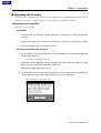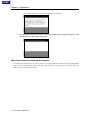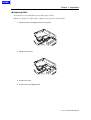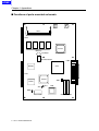
1
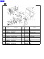
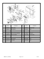
HOME
SERVICE MANUAL
Model
IP-421
SEPTEMBER 2000
CSM-IP421
KONICA BUSINESS TECHNOLOGIES, INC.
HOME
HOME
IP-421
SERVICE MANUAL
SEPTEMBER 2000
Used on Konica Models
7020, 7030
HOME
IMPORTANT NOTICE
Because of the possible hazards to an inexperienced
person servicing this equipment, as well as the risk of
damage to the equipment, Konica Business Technologies strongly recommends that all servicing be performed by Konica-trained service technicians only.
Changes may have been made to this equipment to
improve its performance after this service manual was
printed. Accordingly, Konica Business Technologies,
Inc., makes no representations or warranties, either
expressed or implied, that the information contained in
this service manual is complete or accurate. It is understood that the user of this manual must assume all risks
or personal injury and/or damage to the equipment while
servicing the equipment for which this service manual
is intended.
Corporate Publications Department
© 2000, KONICA BUSINESS TECHNOLOGIES, INC.
All rights reserved.
Printed in U.S.A.
HOME
Contents
CONTENTS
1. Overview
■ Product specifications ............................................................................................... 1-1
● IP-421 print controller ...................................................................................................................... 1-1
■ Product overview ...................................................................................................... 1-3
● Capabilities of the IP-421 ................................................................................................................ 1-3
● Startup sequence of the 7020 series + IP-421 system .................................................................... 1-4
● Data processing of the IP-421 (See data flow) ................................................................................ 1-4
● Data flow ......................................................................................................................................... 1-5
■ Option ....................................................................................................................... 1-6
● KN-303 Network card ...................................................................................................................... 1-6
● Hard Disk (HD-103) ......................................................................................................................... 1-6
● Post Script 3 (PS-341) ..................................................................................................................... 1-6
2. Disassembly/Assembly
■ Construction ............................................................................................................. 2-1
■ Disassembly / Assembly procedures ........................................................................ 2-2
● Removal/Installation of boards ........................................................................................................ 2-2
● Expanding the memory (MU-403/MU-404/MU-405) ........................................................................ 2-5
● Installation / Removal of HD-103 ..................................................................................................... 2-7
● Installation / Removal of PostScript 3 option (PS-341) .................................................................... 2-9
3. Troubleshooting
■ Troubleshooting ........................................................................................................ 3-1
● Troubleshooting of the IP-421 and copier ....................................................................................... 3-1
4. Appendices
■ Upgrading the Firmware ........................................................................................... 4-1
● Rewriting the Flash ROM ................................................................................................................ 4-1
● In case of failure in rewriting the firmware ....................................................................................... 4-2
● Replacing ROM ............................................................................................................................... 4-3
■ Functions of parts mounted on boards...................................................................... 4-4
● Connector ....................................................................................................................................... 4-5
● Switch ............................................................................................................................................. 4-5
● Jumpers .......................................................................................................................................... 4-5
● Individual ICs’ functions ................................................................................................................... 4-5
INDEX ................................................................................................................... Index-1
iii IP-421 PRINT CONTROLLER
HOME
Contents
Blank page
iv IP-421 PRINT CONTROLLER
HOME
SAFETY PRECAUTIONS
SAFETY PRECAUTIONS
Installation Environment
effect may be caused by altering any aspect of the
machine’s design. Such changes have the potential
of degrading product performance and reducing
safety margins.
Safety considerations usually are directed toward
machine design and the possibility of human error. In
addition, the environment in which a machine is operated must not be overlooked as a potential safety
hazard.
For these reasons, installation of any modification not
specifically authorized by Konica Business Machines
U.S.A., Inc., is strictly prohibited.
Most electrical equipment is safe when installed in a
normal environment. However, if the environment is
different from what most people consider to be normal, it is conceivable that the combination of the
machine and the room air could present a hazardous
combination. This is because heat (such as from
fusing units) and electrical arcs (which can occur
inside switches) have the ability to ignite flammable
substances, including air.
The following list of prohibited actions is not all-inclusive, but demonstrates the intent of this policy.
When installing a machine, check to see if there
is anything nearby which suggests that a potential hazard might exist. For example, a laboratory
might use organic compounds which, when they
evaporate, make the room air volatile. Potentially dangerous conditions might be seen or smelled. The
presence of substances such as cleaners, paint thinners, gasoline, alcohol, solvents, explosives, or similar items should be cause for concern.
If conditions such as these exist, take appropriate
action, such as one of the following suggestions.
•
Determine that the environment is controlled
(such as through the use of an exhaust hood) so
that an offending substance or its fumes cannot
reach the machine.
•
Using an extension cord or any unauthorized
power cord adapter.
•
Installing any fuse whose rating and physical size
differs from that originally installed.
•
Using wire, paper clips, solder, etc., to replace or
eliminate any fuse (including temperature fuses).
•
Removing (except for replacement) any air filter.
•
Defeating the operation of relays by any means
(such as wedging paper between contacts).
•
Causing the machine to operate in a fashion other
than as it was designed.
•
Making any change which might have a chance
of defeating built-in safety features.
•
Using any unspecified replacement parts.
General Safety Guidelines
The specific remedy will vary from site to site, but the
principles remain the same. To avoid the risk of injury
or damage, be alert for changes in the environment
when performing subsequent service on any machine, and take appropriate action.
This copier has been examined in accordance with
the laws pertaining to various product safety regulations prior to leaving the manufacturing facility to
protect the operators and service personnel from
injury. However, as with any operating device, components will break down through the wear-and-tear of
everyday use, as will additional safety discrepancies
be discovered. For this reason, it is important that the
technician periodically performs safety checks on the
copier to maintain optimum reliability and safety.
Unauthorized Modifications
The following checks, not all-inclusive, should be
made during each service call:
•
Remove the offending substance.
•
Install the machine in a different location.
CAUTION: Avoid injury. Ensure that the copier is
disconnected from its power source before continuing.
Konica copiers have gained a reputation for being
reliable products. This has been attained by a combination of outstanding design and a knowledgeable
service force.
The design of the copier is extremely important. It is
the design process that determines tolerances and
safety margins for mechanical, electrical, and electronic aspects. It is not reasonable to expect individuals not involved in product engineering to know what
v
•
Look for sharp edges, burrs, and damage on all
external covers and copier frame.
•
Inspect all cover hinges for wear (loose or broken).
•
Inspect cables for wear, frays, or pinched areas.
HOME
SAFETY PRECAUTIONS
•
Ensure that the power cord insulation is not damaged (no exposed electrical conductors).
•
Ensure that the power cord is properly mounted
to the frame by cord clamps.
•
Check the continuity from the round lug (GND) of
the power cord to the frame of the copier -- ensure
continuity. An improperly grounded machine can
cause an electrically-charged machine frame.
Applying Isopropyl Alcohol
Care should be exercised when using isopropyl alcohol, due to its flammability. When using alcohol to
clean parts, observe the following precautions:
Safeguards During Service Calls
Confirm that all screws, parts, and wiring which are
removed during maintenance are installed in their
original positions.
•
When disconnecting connectors, do not pull the
wiring, particularly on AC line wiring and high
voltage parts.
•
Do not route the power cord where it is likely to
be stepped on or crushed.
•
Carefully remove all toner and dirt adhering to any
electrical units or electrodes.
•
After part replacement or repair work, route the
wiring in such a way that it does not contact any
burrs or sharp edges.
•
Do not make any adjustments outside of the
specified range.
•
Remove power from the equipment.
•
Use alcohol in small quantities to avoid spillage
or puddling. Any spillage should be cleaned up
with rags and disposed of properly.
•
Be sure that there is adequate ventilation.
•
Allow a surface which has been in contact with
alcohol to dry for a few minutes to ensure that the
alcohol has evaporated completely before applying power or installing covers.
Summary
It is the responsibility of every technician to use professional skills when servicing Konica products. There
are no short cuts to high-quality service. Each copier
must be thoroughly inspected with respect to safety
considerations as part of every routine service call.
The operability of the copier, and more importantly,
the safety of those who operate or service the copier,
are directly dependent upon the conscientious effort
of each and every technician.
Remember...when performing service calls, use good
judgement (have a watchful eye) to identify safety
hazards or potential safety hazards that may be present, and correct these problem areas as they are
identified -- the safety of those who operate the copier
as well as those who service the copier depend on it!
vi
HOME
OVERVIEW
HOME
HOME
Chapter 1 Overview
■ Product specifications
● IP-421 print controller
Type: Built in Konica 7020 series copy machine
Paper size: 11"X17", 8.5"x14", 8.5"x11", 5.5"x8.5"
Paper feeding: Same as copier
Output stack capacity: Same as copier
Mode: Possible dual mode of copy machine/printer (up to 5 jobs)
Next job reservation: Next copy job can be reserved during print job.
Special printing features: Printing on both faces, choice of paper type, zoom
function, choice of paper tray, choice of output tray,
choice of print quality, Alternate function, sort/group
function, staple function, layout function, front/back
cover intersheet function, booklet function, smoothing function, page protection function, watermark
function
Direction of printing: portrait, landscape
Resolution: 600 dpi
Scan Resolution: 600 dpi/400 dpi/300 dpi/200 dpi
Gradation: 2
Number of output pages: 1-999
Warm-up: Same as copier
CPU: Pentium MMX-166Mhz
Memory: 32MB (standard), expandable up to 160MB (option:MU-403 / MU-404
/ MU-405)
Cards: Controller board x1
PCI relay board x1
KN-303 Network card (option)
Option:Harddisk Drive (HD-103)
PS option (PS-341)
1-1 IP-421 PRINT CONTROLLER
HOME
Chapter 1 Overview
Interface: Parallel port
Based on Centronics (IEEE 1284)/Amphenol male 36pin connector
Network interface: (option)
KN-303 Network card
Network: Ethernet (100BaseTX/10BaseT)
Protocols: IPX/SPX (NetWare),
TCP/IP (LPD/LPR, peer-to-peer)
AppleTalk (EtherTalk)
Compliant OS:
Windows 95/98
Windows NT4.0/2000
Macintosh
Unix
Printer Language:
PCL
PostScript3 (option)
Printer drivers:
Windows 95/98 printer driver
Windows NT4.0/2000 printer driver
Host computer: A Windows based computer
Macintosh
Unix
Finisher: FS-107
paper tray unit: DB-209,DB-409
Size: 9.4 in (W) x 6.3 in (H) x 1.5 in (D)
Weight: Approximately 2.4 lb.
Power source: 5 V, 2 A or less (supplied from copier)
Operating conditions:temperature: 50 - 86oF,
humidity: 20-80%RH (condensation not allowed)
Restrictive Conditions:
* In the Printer mode, the EKC (Electric Key Counter) of the Konica 7020 series is not available.
* Although the Weekly Timer function of the Konica 7020 series is available in
the Printer mode, the power is not turned Off until the data output is finished
when print data remains in the E-RDH.
Notice: Specifications are subject to change for improvements without notice.
1-2 IP-421 PRINT CONTROLLER
HOME
Chapter 1 Overview
■ Product overview
● Capabilities of the IP-421
The Konica IP-421 print controller allows you to use the Konica 7020 series copying machine as a printer
connected to computers and a network. It receives print jobs from computers and network and converts them
into image data (video data) that the Konica 7020 series copying machine prints out.
The IP-421 print controller is characterized as follows.
* Built in the Konica 7020 series copying machine.
* The drivers interfacing with Windows 95/98 and NT4.0/2000 allow use of the functions of
the Konica 7020 series copying machine.
* The KN-303 Network card allows use of the IP-421 as a network printer.
* A system can be upgraded by the renewal of the flash memory.
This Service Handbook describes hardware construction, disassembly and assembly procedures, troubleshooting, and appendixes (upgrading firmware, error messages, etc).
KN-303
(OPTION)
IP-421
1-3 IP-421 PRINT CONTROLLER
HOME
Chapter 1 Overview
● Startup sequence of the 7020 series + IP-421 system
As the IP-421 is built in the 7020 series, supplying power to the IP-421 and its initialization starts as soon as you
turn on the copier. The startup sequence is as follows.
1. Turn on the copier.
Supplying power to start the IP-421 starts. Its CPU works to test the system memory and the
system program starts running.
2. The IP-421 performs system check.
3. On completion of system check, the controller is waiting print job.
If printer mode is selected, a message “Ready to print” appears.
● Data processing of the IP-421 (See data flow)
When you attempt to print a document data from a computer connected the IP-421, processing will be made as
follows.
1. The print job comes from the computer (or network) to the parallel port (or Ethernet port if the KN-303 is
used).
2. The CPU, mounted on IP-421, generates the bit map image of one page to another in the image
memory.
3. The bit map image is transferred in the form of video signals from the image memory to the copier and
printed.
1-4 IP-421 PRINT CONTROLLER
HOME
Chapter 1 Overview
● Data flow
Computer
Browser
HTML
Application
Print Commands
Printer Driver
Spooler
Ethernet I/F
(TCP/IP,IPX/SPX)
Parallel I / F(IEEE1284)
Network Card KN-303
(Option)
Interface
PCI bus
Parallel I / F
Print Controller
Input Buffer
IP-421
Harddisk HD-103
(Option)
PDL Processing (Rasterization)
Graphic memory
PCI bus
Printer Engine
E-RDH memory
Engine(Print)
PDL command
Rasterized graphic data
Printer status
1-5 IP-421 PRINT CONTROLLER
HOME
Chapter 1 Overview
■ Option
● KN-303 Network card
If the IP-421 is fitted with the KN-303 Network card, the 7020 series can be used as a remote printer from any
computer belonging to a network (NetWare/Windows).
● Hard Disk (HD-103)
By installing this optional hard disk to the IP-421, you can use the 7020 series copier as a scanner. The scanned
data can be read into your PC via an optional Network Interface Card.
● Post Script 3 (PS-341)
By installing this optional PostScript and the standard compact •ash for PostScript to the IP-421, you can use the
7020 series copier as a PostScript printer.
1-6 IP-421 PRINT CONTROLLER
HOME
DISASSEMBLY/
ASSEMBLY
HOME
HOME
Chapter 2 Disassembly / Assembly
■ Construction
Expansion memory slot
PDL compact flash slot
Controller Board
PS compact flash slot
CPU cooling fan
HD-103 connector
PCI relay
board
PS-341 slot
Parallel port connector
Printer reray board
(CN502)
Caution:
If grounding is not made securely, the cards can be damaged during work. Make
sure to ground your body securely by using a wrist strap before starting to work.
Tool
* Use a Phillips head screwdriver.
Reference information:
As the IP-421 is provided with a “flash memory”, no tool is needed to replace ROM for
upgrading the firmware.
2-1 IP-421 PRINT CONTROLLER
HOME
Chapter 2 Disassembly / Assembly
■ Disassembly/Assembly procedures
● Removal/Installation of boards
1. Remove the sliding cover. (2 screws)
Sliding cover
2. Remove the Board cover. (11 screws)
Board cover
3. Remove the side cover of the parallel connector side. (5 screws)
Side cover
2-2 IP-421 PRINT CONTROLLER
HOME
Chapter 2 Disassembly / Assembly
4. Remove the printer relay board. (5 screws)
5. Remove the Board cover fixtures. (6 screws)
Board cover fixtures
Board cover fixtures
6. Remove the controller board unit and the side cover of the copying machine side all together.(9
screws)
2-3 IP-421 PRINT CONTROLLER
HOME
Chapter 2 Disassembly / Assembly
7. Pull off the controller board at the connector (CN2) on the PCI relay board fitted to the side cover.
CN4
CN2
8. Remove the PCI relay board. (6 screws)
9. To install, reverse the removal procedure.
Caution:
When installing the PCI relay board, be sure to securely plug in connectors (2 in number).
2-4 IP-421 PRINT CONTROLLER
HOME
Chapter 2 Disassembly / Assembly
● Expanding the memory (MU-403/MU-404/MU-405)
The IP-421 is provided with 32MB memory (standard specification). You can expand the memory capacity up to
160MB by installing a DIMM card additionally into a slot on the controller board.
Caution:
* With the memory expanded, the IP-421 can rasterise more pages during waiting previous
print job than before expansion.
* If memory overflow occurs, expand the memory.
* The memory card slot is prepared for expansion of 32MB, 64MB or 128MB.
* When a memory except for Konica designation, the movement of IP421 can’t be assured.
Installing DIMM
1. Insert the connector of DIMM obliquely.
2-5 IP-421 PRINT CONTROLLER
HOME
Chapter 2 Disassembly / Assembly
2. Push the end of the DIMM and lock it with levers provided on both sides of the socket.
Caution:
The DIMM card can fit into the socket only in such a direction that the notch provided on the
bottom of DIMM matches with the one on the socket.
Removing DIMM
1. Release the lock levers provided on both sides of the socket. Take out the DIMM in the upper oblique
direction.
2-6 IP-421 PRINT CONTROLLER
HOME
Chapter 2 Disassembly / Assembly
● Installation / Removal of HD-103
1. Remove the Board cover on the IP-421. (11 screws)
Board cover
2. Remove the printer relay board. (3 screws), then remove the flash card stopper plate. (2 screws)
Printer relay board
Flash card
stopper plate
3. Connect the HDD to the connector of the printer relay board.
Caution:
Take care not to bend or break the pins of HDD.
HDD
Printer relay board
2-7 IP-421 PRINT CONTROLLER
HOME
Chapter 2 Disassembly / Assembly
4. Fix the HDD on the printer relay board with 4 screws.
Printer relay board
5. Fit the printer relay board into the connector of the IP-421 print controller.
6. Fix the flash card stopper plate with two screws, then fix the printer relay board with three screws.
Printer relay board
7. Fix the board cover on the IP-421. (11 screws)
8. To remove, reverse the installation procedure.
2-8 IP-421 PRINT CONTROLLER
Flash card
stopper plate
HOME
Chapter 2 Disassembly / Assembly
● Installation / Removal of PostScript 3 option (PS-341)
1. Remove the Board cover on the IP-421. (11 screws)
Board cover
2. Remove the printer relay board. (3 screws), then remove the flash card stopper plate. (2 screws)
Printer relay board
Flash card
stopper plate
3. Mount the Flash card on the printer relay board.
Caution:
Position the Flash card in correct direction as illustrated below.
2-9 IP-421 PRINT CONTROLLER
HOME
Chapter 2 Disassembly / Assembly
4. Mount the PS-341 on the print controller board.
Caution:
Position the PS-341 by matching the cut corner to that on the board.
PS-341
5. Fit the printer relay board into the connector of the IP-421 print controller.
Printer relay board
6. Fix the flash card stopper plate with two screws, then fix the printer relay board with three screws.
Printer relay board
Flash card
stopper plate
7. Fix the board cover on the IP-421. (11 screws)
8. To remove, reverse the installation procedure.
Caution:
To remove the PS-341, use a PCLL removing tool.
2-10 IP-421 PRINT CONTROLLER
HOME
TROUBLESHOOTING
HOME
HOME
Chapter 3 Troubleshooting
■ Troubleshooting
This section offers a summary of information on troubleshooting that technicians could refer to easily and would
minimize the time of interruption of work.
● Troubleshooting of the IP-421 and copier
Symptoms
Causes
Actions
Printer mode window does not
appear on the copier’s display
after power-on.
No power supply to the IP-421.
Check if the IP-421 is connected
with the copier properly.
“Warming up” does not disappear.
Copier is in trouble.
Locate the cause of trouble of
the copier.
“Initialization ” does not disappear on the copier screen.
The IP-421 has not started properly.
See the column of “IP-421 does
not start”.
Printout is defective, or nothing
can be printed.
The controller board or some
boards of the copier are defective.
Put the copier in 36 mode and
perform test. If it operates properly, controller board may be
failure.
IP-421 does not start.
The controller board is inactive.
Check the connector of the controller board. Replace the controller board as necessary.
Software of the IP-421 is destroyed.
Reinstall the software of the IP421.
The parallel port has something
wrong or the cable is wrong
or, the problem is on the computer side.
Check the cables (internal/external). Perform test using a
data generator or a well-proven
PC/I/O cable. Replace the controller board as necessary.
Test print can be produced but
not from the parallel port.
3-1 IP-421 PRINT CONTROLLER
HOME
Chapter 3 Troubleshooting
Symptom
Test print can be produced but not
from the network port.
Possible causes
The network card is inactive or not
installed properly.
Actions
Examine the network card. Check
all connectors. Replace the network card as necessary.
Test print can be produced and
all ports are good, but user jobs
cannot be printed.
Some software error has happened.
IP-421’s software or application
program has something wrong.
Save the file, which failed to be
printed, in the disk and analyze
the problem by suitable means.
3-2 IP-421 PRINT CONTROLLER
HOME
APPENDICES
HOME
HOME
Chapter 4 Appendices
■ Upgrading the Firmware
The IP-421 uses a compact flash ROM and you can go two ways in upgrading the firmware.You can
update the firmware via a parallel port or you can replace the compact flash ROM.
● Rewriting the Flash ROM
Normally, use this method.
Preparation
• Connect the IP-421 through a parallel cable to the computer that is used to upgrade the
firmware.
• Prepare the replacing firmware in the hard disk of the computer or in the form of CD-ROM.
• Turn on the copier’s main and auxiliary powers.
Procedure of rewriting the firmware
1. On the monitor screen of the computer, click the Start button. Click and select [MS-DOS
Prompt] from [Program].
The [MS-DOS prompt] appears.
2. Responding to the [MS-DOS prompt], designate the folder where the firmware is held.
Execute a COPY command and press the Enter key.
<Example> C:\copy filename.xxx lpt1 /b
3. On completion of file transfer from the computer, a message indicating the completion of
transfer appears on the copier LCD control panel. Press the OK button.
Now rewriting the firmware starts.
4-1 IP-421 PRINT CONTROLLER
HOME
Chapter 4 Appendices
A message indicates that the firmware is being rewritten.
4. On completion of firmware renewal, a message indicating the completion appears. Then
turn off and on the Main SW of the copier.
● In case of failure in rewriting the firmware
If rewriting the firmware fails for some reason, it may be possible to redo the rewriting procedure
when the error happened in file transfer from the computer. Turn off and on the Main SW of the
copier and try the procedure again.
4-2 IP-421 PRINT CONTROLLER
HOME
Chapter 4 Appendices
● Replacing ROM
The firmware can be upgraded even by replacing the ROM.
Replace the ROM if it is impossible to update the firmware via a parallel port.
1. Remove Flash card stopper plate on sub panel.
2. Remove Flash card.
3. Install Flash card.
4. Install Flash card stopper plate.
4-3 IP-421 PRINT CONTROLLER
HOME
Chapter 4 Appendices
■ Functions of parts mounted on boards
CN1
CN8
PCIset
Memory
Oscillator
Clock Generator
CN9
KPC01
CPU
CN7
PCIset
SW1
PPBC
JP2
JP3
CN3
SW2
Boot ROM
4-4 IP-421 PRINT CONTROLLER
CN4
CN5
HOME
Chapter 4 Appendices
● Connector
CN1: Expansion memory
CN3: PS-341 (option)
CN4: Printer relay board
CN5: Printer relay board
CN7: PCI relay board
CN8: PCI relay board
CN9: Parallel port connector
● Switch
SW1: Resets system. (only for development purpose)
No need to operate the switch.
SW2: Switch boot system. (only for development purpose) No need to use the switch.
● Jumpers
No need to use the jumpers.
JP2: Not installed (no function)
JP3: For production purpose
● Individual ICs’ functions
CPU:
Central processing unit
BootROM: System booting-up parameter
KPC01:
Image rotation through 90 degrees/error diffusion processing
PPBC:
Bridge from each PCIset to the PCI bus
PCIset:
Bridge from different points to PPBC
4-5 IP-421 PRINT CONTROLLER
HOME
HOME
INDEX
INDEX
A
R
Assembly .............................................................. 2-2
ROM ..................................................................... 4-3
B
S
Boards .................................................................. 4-4
SAFETY AND IMPORTANT WARNING ITEMS ...... vi
Specifications ....................................................... 1-1
Startup sequence ................................................. 1-4
Switch ................................................................... 4-5
C
Connector ............................................................. 4-5
Construction ......................................................... 2-1
D
T
Troubleshooting ................................................... 3-1
Data flow .............................................................. 1-5
DIMM ............................................................ 2-5, 2-6
Disassembly ......................................................... 2-2
E
Expanding the memory ........................................ 2-5
F
Firmware .............................................................. 4-1
Flash memory ....................................................... 1-3
Flash ROM ........................................................... 4-1
H
HD-103 ......................................................... 1-6, 2-7
I
IC
...................................................................... 4-5
J
Jumpers ............................................................... 4-5
K
KN-303 ................................................................. 1-6
M
MU-403 ................................................................ 2-5
MU-404 ................................................................ 2-5
MU-405 ................................................................ 2-5
P
PostScript 3 option ............................................... 2-9
Protocols .............................................................. 1-2
PS-341 ......................................................... 1-6, 2-9
Index-1
HOME
INDEX
Blank page.
2-Index
HOME
IP-421
Ref.
No.
Part No.
Ref.
No.
Part No.
1
13FM73191
Auxiliary spring
12
13FM73170
Ground spring/2
2
13FM73131
Slide part/lower
13
450011270
Screw
3
13FM73200
Electricity seal
14
13FM73030
Board mount plate/C
4
13FM73140
Slide part/upper
15
13JA-9030
Printer relay board assembly/3
5
13JA-9020
Printer relay board assembly/2
16
13JA80510
Cooling fan
6
13FM73040
Board cover plate/A
17
13JA73020
Fan mount plate
7
13FM73100
Board support plate/E
a
00Z670306
E-ring
8
13JA-9010
Printer control board assembly
b
00Z113065
Screw
9
13FM73180
Ground spring/3
c
00Z193041
Screw
10
13FM73090
Cover plate/1
d
00Z183042
Screw
11
13FM73110
Spring hold plate
e
00Z193201
Screw
Description
Description
PRODUCT:
IP-421
NO.:
1
DATE:
10/30/00
For 7020, 7030
SUBJECT:
Th i s
PARTS AVAILABILITY
b u l l e t i n p r o v i d e s p a r t s i n f o r m a t i o n f o r t h e I P - 4 2 1 p r i n t c o n t r o l l e r ( P C U A 9 5 0 - 2 2 9 ) . P l e as e
refer to page 2.
28-2
IP-421
Corporate Publishing Services
Page 1 of 2
Bulletin #1 (10/30/00)
Ref.
No.
Part No.
Ref.
No.
Part No.
1
13FM73191
Auxiliary spring
12
13FM73170
Ground spring/2
2
13FM73131
Slide part/lower
13
450011270
Screw
3
13FM73200
Electricity seal
14
13FM73030
Board mount plate/C
4
13FM73140
Slide part/upper
15
13JA-9030
Printer relay board assembly/3
5
13JA-9020
Printer relay board assembly/2
16
13JA80510
Cooling fan
6
13FM73040
Board cover plate/A
17
13JA73020
Fan mount plate
7
13FM73100
Board support plate/E
a
00Z670306
E-ring
8
13JA-9010
Printer control board assembly
b
00Z113065
Screw
9
13FM73180
Ground spring/3
c
00Z193041
Screw
10
13FM73090
Cover plate/1
d
00Z183042
Screw
11
13FM73110
Spring hold plate
e
00Z193201
Screw
Bulletin #1 (10/30/00)
Description
Page 2 of 2
Description
IP-421
TECHNICAL
BULLETIN
A copy of this bulletin must be given to every technician who services this model.
PRODUCT:
IP-421
NO:
2
DATE:
9/26/02
For: 7020, 7025, 7030, 7035
SUBJECT:
FLASH CARD UPGRADE
PostScript & PCL Flash Cards Included in PS-341 Kits
Purpose of Change
th
The 4 generation PostScript flash card (xxxxxxxxC4) included with PostScript kit PS-341 is no longer available.
Where Changed
th
A 6 generation PostScript flash card (xxxxxxxxC6) is now included in PS-341 kits.
th
With the upgrade of the PostScript flash card, an incompatibility issue arises with IP units equipped with 4
generation flash cards containing system code and PCL, such as unrecognizable handshaking signals, etc.
between PostScript and the IP unit.
th
To address this incompatibility, an additional 6 generation flash card for PCL is now being included in
PostScript kits for upgrading the IP unit if necessary. The table provides the compatibility of the possible flash
card combinations.
th
6 Generation
6 Generation
th
No
th
4 Generation
4 Generation
th
Yes
PCL Flash Card (IP unit)
4 Generation
PostScript Flash Card
Compatibility
Applicability
th
6 Generation
th
4 Generation
th
6 Generation
Yes
Yes
th
th
PostScript kit PS-341 beginning with serial number 13JF09843 includes both the 6 generation PCL and
PostScript flash cards.
Action and Result
Which PCL Flash Card is Installed?
Before installing the PostScript kit, determine what generation PCL
flash card is installed in the IP unit (see illustration for ID location). If a
th
4 generation PCL flash card is installed (xxxxxxxxC4), use both flash
cards provided in the kit for this upgrade.
Preparing the Flash Cards
th
Prior to installing, upgrade the firmware level of the 6 generation flash
cards provided in the kit to version 5.5.3 or higher for PCL and version
5.5.0 or higher for PostScript using the flash card update method. The
DOS/parallel cable method is not available for PCL/PostScript
combination code updates.
The PCL flash card can be identified by “13JB” printed on its label;
“13JE” is printed on the PostScript flash card label.
IP-421
Page 1 of 2
PCL Flash Card
Bulletin #2 (9/26/02)
Installing the Flash Cards
th
th
Replace the 4 generation PCL flash card in the IP unit with the newest 6 generation flash card (xxxxxxxxC6)
using the instructions provided with the PostScript kit or firmware upgrade ReadMe files.
28-3
IP-421
Corporate Publishing Services
Page 2 of 2
Bulletin #2 (9/26/02)