1
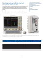
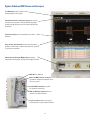
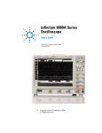
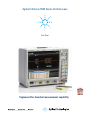
Agilent Ininiium 9000 Series Oscilloscopes
Data Sheet
Engineered for broadest measurement capability
If you haven’t purchased an Agilent scope lately,
why should you consider one now?
If you’re like most engineers, you never know what your next project will demand from you.
You need an oscilloscope that can adapt to a wide variety of debug and test challenges.
That’s why we designed our new Ininiium 9000 Series oscilloscope to meet a full range
of needs.
There is no better way to experience
the superiority of the Infiniium 9000 Series
scopes than to see it.
Contact Agilent today to request an
evaluation.
Or visit:
www.agilent.com/find/9000
First we built in the powerful features you’d expect in any Ininiium scope. Then we
engineered the scope for the broadest measurement capability, so it would be the most
indispensable tool in your arsenal.
The Infiniium 9000 Series offers bandwidths up to 4 GHz. Each model, equipped with a large 15” XGA LCD display, comes in a whisper-quiet
package that is just 9” (23 cm) deep and weighs only 26 pounds (11.8 kg).
Analog sample rate
4-channel/2-channel
Standard memory
4-channel/2-channel
Model
Analog bandwidth
Scope channels
Logic channels
DSO9064A
600 MHz
5 GSa/s/10 GSa/s
20 Mpts/40Mpts
4
-
MSO9064A
600 MHz
5 GSa/s/10 GSa/s
20 Mpts/40Mpts
4
16
DSO9104A
1 GHz
10 GSa/s/20 GSa/s
20 Mpts/40Mpts
4
-
MSO9104A
1 GHz
10 GSa/s/20 GSa/s
20 Mpts/40Mpts
4
16
DSO9254A
2.5 GHz
10 GSa/s/20 GSa/s
20 Mpts/40Mpts
4
-
MSO9254A
2.5 GHz
10 GSa/s/20 GSa/s
20 Mpts/40Mpts
4
16
DSO9404A
4 GHz
10 GSa/s/20 GSa/s
20 Mpts/40Mpts
4
-
MSO9404A
4 GHz
10 GSa/s/20 GSa/s
20 Mpts/40Mpts
4
16
2
What makes the Infiniium 9000 Series the go-to scope for a whole range of
test and debug challenges?
It’s three instruments in one
1. Scope: The powerful features of our Ininiium Series oscilloscopes coupled with
superior speciications give you precise signal representation.
2. Logic analyzer: Fast deep-memory digital channels let you see critical data values
and timing relationships.
3. Protocol analyzer: The world’s irst scope-based protocol viewer with multi-tab
viewing. Quickly drill and move between protocol and physical layers.
It offers the widest range of debug and compliance application software
Need accurate answers to your measurement questions? The Ininiium 9000 Series offers
the largest range of application-speciic software for debug, analysis and compliance testing. Which application is right for you? Take a look at the possibilities on pages 7-12.
It’s sized to fit your environment
Limited bench space? It has a small footprint and thin proile
Height: 12.9” (33 cm); width: 16.8” (43 cm); depth: just 9” (23 cm)
Need to share the scope? It’s light weight: 26 lbs. (11.8 kg)
Need to see lots of signals? It has the biggest screen: 15” (23 cm) XGA
3
It’s three instruments in one
1. Oscilloscope
High-performance scope channels ensure superior viewing of signals under test. All models incorporate a powerful, feature-packed Infiniium oscilloscope with responsive deep memory.
Up to 4 GHz bandwidth and 20 GSa/s high sample rates guarantee you’ll see a
precise representation of the analog characteristics of signals you’re testing.
Mask tests, histograms and a wide variety of functions such
as the gated FFTs in the above image provide deep signal
analysis.
Responsive deep memory
Advanced triggering
Drag and drop measurements
With standard 20 Mpts/ch, and up to 1 Gpts/
ch of memory, you can capture long time
periods while retaining fast sample rates.
Fast update rates mean your scope stays
responsive with deep memory on, ensuring
precise representation of analog signals.
Advanced triggers are essential when you are
investigating suspected problems. Ininiium
offers a full range of advanced triggers to
help you isolate and capture the condition
you need to characterize. The 9000 Series
simpliies trigger setups by using intuitive
dialog boxes with descriptive graphics.
It’s simple: drag an icon from the measurement bar and drop it on the cycle you want to
measure. You can make up to ten measurements on your waveforms. All of the measurements appear at the bottom of the display with
statistics and are color-coded to the channel
you are measuring.
4
It’s three instruments in one
2. Logic analyzer
MSO models add 16 high-speed timing channels with standard 128 Mpts digital memory, allowing you to retain fast 2 GSa/s sample rates
over long periods of time.
Use the timing channels to evaluate control signal relationships and data buses
up to 16 bits wide. Use symbols to more quickly interpret waveforms.
Digital and mixed-signal trigger
Trigger on and display individual
signals or buses. With precise
time-correlation between analog
and digital signals, conidently trigger across any combination
of analog and digital signals
simultaneously.
Designing with Altera or Xilinx FPGAs? Use the FPGA
dynamic probe for rapid internal FPGA measurements. Using
I²C, SPI, RS-232, or low- or full-speed USB? Use the digital
channels to acquire and decode these buses, preserving
analog channels for other time-correlated measurements.
Industry’s only segmented memory for both
analog and digital channels
Capture short bursts without consuming
memory during periods when the trigger
condition is not met. Agilent is the only
vendor that supports segmented memory
capture on both analog and digital channels.
5
Waveform and Listing Windows
View buses as waveforms or easily follow
events in the listing window expandable to
the entire display. A blue tracking marker
provides time-correlation between waveform
and listing displays.
It’s three instruments in one
3. Protocol analyzer
Does your design include a serial bus that is a key point for testing or debugging? Add protocol analysis capability to your scope for:
• CAN
• FlexRay
• I2C
• JTAG
• LIN
• MIPI D-Phy
• PCle
• RS-232/UART
• SATA
• SPI
• USB
• 8B/10B
• digRF
• SVID
Quickly move between physical and protocol layer information using the time-correlated
tracking marker. Display protocol content using waveform symbols and the industry’s first
multi-tab protocol viewer. The packets tab shows a high level view of the packet over time.
Protocol-level triggering makes it easy to
isolate events with pinpoint accuracy.
Use any combination of analog or digital channels for serial protocol decode, with
up to four buses decoded simultaneously.
Header tab shows packets in a databook format. Hovering on any tab reveals additional
detail.
6
Widest range of debug and compliance software applications: serial protocol-level
I2C/SPI serial trigger and decode (N5391B-1NL* or Option 007 on new scope purchases)
This application displays real-time time-aligned decode of I2C and SPI serial buses. Hardware-based
triggering means triggering reliably, even on the most infrequent events.
This application works on all models and can use any combination of scope or logic acquisition
channels.
For more information: www.agilent.com/find/9000_I2C-SPI
Trigger and view on-screen serial decode
of I2C packets.
RS-232/UART serial decode and trigger (N5462B-1NL* or Option 001 on new scope purchases)
This application eliminates the need to manually decode bus trafic. Using data captured on the
scope or logic channels, the application lets you easily view the information sent over an RS-232
RS-422, RS-485 or other UART serial buses.
Display real-time time-aligned decode of transmit and receive lines. Hardware-based triggering
means triggering reliably, even on the most infrequent events.
This application works on all models and can use any combination of the scope or logic acquisition
channels.
Trigger on and decode RS-232/UART
transmission.
For more information: www.agilent.com/find/9000_RS-232
CAN, LIN and FlexRay triggering and decode (N8803B-1NL* or Option 008 on new scope purchases)
Trigger on and view both protocol layer information and physical layer signal characteristics for
CAN, LIN and FlexRay buses. Numerical decode values are automatically displayed and
synchronized below the captured signal or seen in protocol viewer.
Hardware-based triggering for CAN and LIN means triggering reliably, even on the most infrequent
events. FlexRay uses software-based protocol triggering.
This application works on all models and can use any combination of scope or logic acquisition
channels.
Trigger on and decode CAN, LIN and
FlexRay serial packets.
For more information: www.agilent.com/find/9000_CAN
JTAG (IEEE 1149.1) triggering and decode (N8817B-1NL* or Option 042 on new scope purchases)
This application displays real-time time-aligned decode of JTAG (IEEE 1149.1) TDI and TDO signals.
The application eliminate the dificult task of manually determining JTAG TAP controller states, instruction and data register decode, and lags error conditions. The application includes scan chain
description features including the ability to import .bsdl iles for each device and displays device
names and opcodes in the protocol listing.
This application works on all models and can use any combination of scope or logic acquisition
channels.
Import BSDL files and decode JTAG
scan chain activity.
For more information: www.agilent.com/find/9000_JTAG
*Use option -1FP for Ininiium 5.0 and above
7
Widest range of debug and compliance software applications: serial protocol and FPGA
USB serial trigger and protocol viewer (N5464-1NL* or Option 005 on new scope purchases)
Trigger on and quickly view USB packets, payload, header and detail information. Powerful
time-correlated views of waveform and symbol, to the bit level, make it easy to isolate
communication faults to logic or analog sources.
USB hardware-based triggering means triggering reliably, even on the most infrequent events.
Low and full-speed USB protocol is supported on digital and scope channels of all models.
High-speed USB protocol is supported on scope channels of 1 GHz, 2.5 GHz and 4 GHz models.
For more information: www.agilent.com/find/9000_USB
Trigger on and decode USB packets.
MIPI D-Phy serial decode and trigger (N8802B-1NL* or Option 019 on new scope purchases)
This application eliminates the need to manually decode bus trafic. Using data captured on the
scope, the application lets you easily view the information sent over MIPI serial buses.
The application also enables software-based protocol triggering.
This application works on all 4 GHz models and can use any combination of the scope
channels
For more information: www.agilent.com/find/N8802A
Trigger on and decode MIPI packets
PCI Express® serial trigger and protocol viewer (N5463B-1NL* or Option 006 on new scope
purchases)
This application provides protocol-level triggering and viewing of a PCIe® lane. Quickly view packets, payload, header, and detail information. Powerful time-correlated views of waveform, symbol,
character, link and transaction layer packet data down to the bit level make it easy to isolate communication faults to logic or analog sources.
Trigger on and view CRC, 8B/10B and disparity errors. Hardware-based triggering for PCIe means
triggering reliably, even on the most infrequent events.
Trigger on and decode PCIe serial packets.
This application is supported on scope channels of 4 GHz models.
For more information: www.agilent.com/find/9000_PCI
SATA triggering and decode (N8801B-1NL* or option 038 on new scope purchases)
Trigger on and view both protocol layer information and physical layer signal characteristics
for SATA 1 (1.5 GB/s). Numerical decode values are automatically displayed and synchronized
below the capture signal or seen in protocol viewer.
This application enables software-based protocol triggering. This application works on 4 GHz
and can use any combination of scope channels
For more information: www.agilent.com/find/N8801A
Trigger on and decode SATA serial
packets
*Use option -1FP for Ininiium 5.0 and above
8
Widest range of debug and compliance software applications: serial physical-layer
USB 2.0 compliance testing (N5416B-1NL* or Option 029 on new scope purchases)
Quickly determine USB compliance with this USB-IF recognized solution. A setup
wizard guides you through test selection and coniguration.
This application is USB-IF approved and supported on all 2.5 GHz and 4 GHz models.
For more information: www.agilent.com/find/9000_USB-compliance
Check for USB compliance.
DDR1 and LPDDR/DDR2 and LPDDR2/DDR3 compliance testing (U7233B-1NL*/
N5413C-1NL*/U7231C-1NL* or Options 031/032/033 on new scope purchases) or
N5459C-1NL* for all memory applications
Quickly and easily evaluate and characterize your memory designs. Automated testing based
on JEDEC speciications saves time. The application also includes additional debug and compliance capabilities.
This application is supported on all models. However, the DDR technology you are using may
dictate the minimal bandwidth required for your scope.
Test DDR memory.
For more information: www.agilent.com/find/9000_DDR
Ethernet and Energy Efficient Ethernet compliance testing (N5392C-3NL** and N5392C-1NL*
or Options 065 and 060 on new scope purchases)
Perform a wide range of electrical tests for 10-, 100-, and 1000-Base-T systems. An N5395C
test ixture and N5396A jitter test cable speed compliance testing.
These applications are supported on all 600 MHz and higher bandwidth models.
For more information: www.agilent.com/find/9000_ethernet
Validate Ethernet compliance.
MIPI compliance testing (U7238D-1NL* or Option 035 on new scope purchased)
Quickly validate your embedded D-Phy data link for CSI and DSI architectures. This software
performs a wide range of tests required for meeting MIPI D-Phy physical layer requirements.
These applications are is supported on analog channels of all 4 GHz models.
For more information: www.agilent.com/find/U7238A
Check for MIPI compliance.
*Use option -1FP for Ininiium 5.0 and above
** Use option -3FP for Ininiium 5.0 and above
9
Widest range of debug and compliance software applications: InfiniiScan and jitter analysis
InfiniiScan event identification (N5415B-1NL* or Option 009 on new scope purchases)
Rapidly trigger on complex events and identify signal integrity issues.
This innovative software quickly scans through thousands of acquired waveform cycles and
isolates anomalous signal behavior. Up to eight zones across channels are available.
This application is supported on all models.
For more information: www.agilent.com/find/infiniiScan
Identify signal integrity issues with InfiniiScan
Zone – Qualify triggering.
EZJIT analysis software (E2681B-1NL* or option 002 on new scope purchases)
Quickly characterize and evaluate most commonly needed jitter measurements, including cyclecycle, N-cycle, period, time-interval, error, setup and hold time, histograms, measurement trending
and jitter spectrum.
This application is supported on all models.
For more information: www.agilent.com/find/EZJIT
Conduct jitter analysis.
EZJIT Plus analysis software (N5400B-1NL* or Option 004 on new scope purchases.)
EZJIT Plus adds additional compliance views and an expanded measurement setup wizard to
simplify and automate RJ/DJ separation for testing against industry standards.
This application is supported on all models.
For more information: www.agilent.com/find/EZJITPlus
Analyze jitter plus RJ/DJ separation.
EZJIT Complete analysis software (N8823B-1NL* or Option 070 on new scope purchases.)
EZJIT Complete includes all of the advanced jitter analysis capabilities of EZJIT and EZJIT Plus,
and adds advanced analysis of the vertical noise affecting the ones and zeros of your real-time eye.
Decomposition of vertical noise provides key insight into degradation of your eye height. In
providing advanced decomposition of both horizontal jitter and vertical noise components of your
signals, EZJIT Complete represents the most comprehensive analysis software available.
This application is supported on all models and is standard on DSA models.
For more information: www.agilent.com/find/EZJITComplete
EZJIT Complete.
*Use option -1FP for Ininiium 5.0 and above
10
Widest range of debug and compliance software applications: viewing and analysis
High-speed serial data analysis software (N5384A-1NL* or Option 003 on new scope purchases)
Quickly validate signal integrity for high-speed serial interfaces with embedded clocks. Recover
embedded clocks synchronized with the analog waveform view. Build and validate eye diagrams.
The SDA package also includes software-based bit-level triggering and decode for 8B/10B.
This application is supported on all models.
For more information: www.agilent.com/find/9000_SDA
Recover embedded clocks with serial data
analysis (SDA).
Vector signal analysis software (89601B)
Expand the measurement capability of your scope with the 89601B vector signal analysis software.
This advanced DSP-based software takes the digitized signal data from the scope. Then it provides
FFT-based spectrum analysis and wide-bandwidth digital modulation analysis for wireless
communication signals such as WCDMA and cdma2000 and wireless networking signals such as
802.11 WiFi and 802.16 WiMax.
Take advantage of the super-wide bandwidth of your scope to capture and evaluate radar signals.
Use vector signal analysis software to see
FFT-based spectrum analysis.
For more information: www.agilent.com/find/VSA
User-defined function (N5430B-1NL* or Option 010 on new scope purchases)
Install MATLAB® on your scope and add your favorite MATLAB .m scripts as function operators
and use them as standard waveform functions.
This application is supported on all models and requires MATLAB software (not included with UDF)
For more information: www.agilent.com/find/UDF
Signal equalization using user-defined
function.
*Use option -1FP for Ininiium 5.0 and above
11
Infiniium 9000 Series applications and upgrades
User-definable application (N5467C-1NL*)
Rapidly develop your own automated measurements and tests. This application provides the
framework you need to quickly program and automate any single or set of measurements the
oscilloscope can make.
The application also provides full control of other Agilent instruments and HTML reporting capabilities.
For more information: www.agilent.com/find/9000_UDA
Quickly automate oscilloscope measurements.
FPGA dynamic probe application (N5397A-1NL* or Option 016 on new scope purchases)
Agilent’s MSO FPGA dynamic probe provides internal FPGA visibility and quick instrument
setup using an innovative core-assisted debug approach. Measurement tasks that previously
took hours can be done in seconds with a few mouse clicks.
This application is supported on all MSO models.
For more information: www.agilent.com/find/9000_xilinx
Rapid FPGA debug.
Power application (U1882A or Option 015 on new scope purchases)
Agilent’s power application provides a full suite of power measurements. Make more accurate
power-supply eficiency measurements by using an U1880A de-skew ixture to de-skew your voltage and current probes.
This application is supported on all models.
For more information: www.agilent.com/find/9000_power-app
Use your scope to quickly make and analyze
power measurements.
PrecisionProbe software (N2808A-1NL*)
Make more accurate measurements independent of what probes or cables used. Agilent’s
N2808A PrecisionProbe software characterizes and corrects for the loss in your speciic cable or
probe. PrecisionProbe removes the uncertainty about the input connected to your oscilloscope by
allowing you to see its characteristics in less than ive minute. PrecisionProbe gives you design
and debug conidence by allowing you to quickly de-embed probe and cable loss to make more
accurate measurements.
For more information: www.agilent.com/find/PrecisionProbe
Quickly characterize and correct for any
input to your oscilloscope
Infiniium Offline Oscilloscope Analysis Software (N8900A)
Wish you could do additional signal viewing, analysis and documentation tasks away from
your scope and target system? With Agilent’s IniniiView oscilloscope analysis software
you can. Capture waveforms on your scope, save to a ile, and open the data record into
Agilent’s IniniiView application. View, analyze, share, and document scope measurements
anywhere your PC goes.
12
*Use option -1FP for Ininiium 5.0 and above
Agilent Infiniium portfolio
Agilent’s real-time Infiniium lineup includes 9000, S-Series, 9000 H-, 90000A and 90000 X Series oscilloscopes. These share a number of advanced hardware and software technology blocks. Use the following selection guide to determine which best matches your specific needs.
Widest range of applications.
Biggest display plus thin depth
See your signals in HD
New standard in signal integrity
Low noise, high bandwidth
9000 Series
9000 H-Series
S-Series
90000 Series
Bandwidth
Up to 4 GHz
Up to 2 GHz
Up to 8 GHz
Up to 13 GHz
50 Ω & 1 MΩ inputs
Yes
Yes
Yes
1 M Ω with adapter
MSO models
Yes
Yes
Yes
Max 2-channel (4-channel)
sample rate
20 GSa/s
(10 GSa/s)
10 GSa/s
(10 GSa/s)
20 GSa/s
(10 GSa/s)
40 GSa/s
(40 GSa/s)
GPIB
N4865A GPIB to LAN
adapter
8U
N4865A GPIB to
LAN adapter
8U
Built in option
Rackmount height
N4865A GPIB to LAN
adapter
8U
Display size
15”
15”
15”
12”
13
7U
Agilent Infiniium 9000 Series oscilloscopes
15” XGA display makes it easier to view
analog, digital and serial signals.
Comprehensive built-in information system gives you fast
answers to your questions. The task-oriented setup guide
provides step-by-step instructions for several measurement
procedures.
Touchscreen display comes standard for mouse-free
operation.
Drag-and-drop measurements from the measurement bar
provide an intuitive way to make a measurement on a particular cycle of your waveform.
Mixed-signal oscilloscope (MSO) models seamlessly
integrate four analog scope channels with 16 digital channels.
AUX OUT for calibration
Built-in 10-MHz reference in/out port
synchronizes multiple measurement instruments in a system.
Standard USB and LAN ports provide
PC and printer connectivity.
XGA and DVI video output port lets you
connect to an external monitor.
Trig in/out ports provide an easy way to
synchronize your scope to other instruments.
14
Dedicated single acquisition button provides better control to
capture a unique event.
Pressing horizontal delay knob sets the delay to zero. A zoom
button provides quick access to two screen-zoom modes.
MegaZoom instant response and optimum resolution allows
you to pan and zoom quickly.
Autoscale lets you rapidly display any analog or digital active
signals, automatically setting the vertical, horizontal and
trigger controls for the best display, while optimizing memory.
Digital channel button provides quick setup access.
Serial decode button enables quick setup access.
Dedicated per-channel front panel controls make it easy to
access the vertical and horizontal scaling and offset.
Quick access to fine/vernier control by pressing the horizontal and vertical sensitivity knobs.
AutoProbe interface automatically
conigures the attenuation ratio of the
probe and provides probe power for
Agilent’s active probes.
Built-in USB ports makes it easy
to save your work and update your
system software quickly.
Accessory pouch detaches easily.
15
Connectivity and probing
Connectivity
Probing
Industry compatibility
Each Ininiium 9000 Series oscilloscope ships
with four N2873A 10:1 divider passive probes
and probe accessory pouch.
Export screen shots and waveforms in
numerous industry-standard formats.
In addition, the 9000 Series supports
compatibility with the following
• MATLAB Basic and Advanced (add as 061
and 062 on new scope orders)
• IVI COM driver for application development
environments such as Visual Studio, Agilent
VEE, NI LabView and MATLAB instrument
control toolbox.
www.agilent.com/find/adn
• IntuiLink tool bars and data capture.
www.agilent.com/find/intuilink
• LXI Class C including built-in Web control
With both 50 Ω and 1 MΩ inputs, Ininiium
9000 Series scopes support a wide range of
probes, including Agilent’s IniniiMax and
IniniiMode Series probes.
Agilent offers an innovative family of probes
that are engineered for signal access and
measurement accuracy. Whether you’re
looking for simple passive probes, the high
bandwidth and low loading of an active
probe, or specialty probes for current or high
voltage, we can meet your needs. Our innovative accessories allow reliable connection
to challenging
• NI LabView PnP and IVI drives
www.agilent.com/find/ni9404
Recommended optional active probes
DSO/MSO9404A 1132A IniniiMax 5 GHz probe
N2752A IniniiMode 6 GHz probe
DSO/MSO9254A 1131A IniniiMax 3.5 GHz probe
N2751A IniniiMode 3.5 GHz probe
DSO/MSO9104A N2796A 2 GHz single-ended probe
1130A IniniiMax 1.5 GHz probe
N2750A IniniiMode 1.5 GHz probe
DSO/MSO9064A N2795A 1 GHz single-ended probe
N2750A IniniiMode 1.5 GHz probe
16
components like small pitch devices,
surface mount ICs, and DDR BGA packages – even hands free! To see our entire
award-winning portfolio of passive, singleended active, differential active, and
current probes for Ininiium oscilloscopes,
please view the Ininiium Oscilloscope
Probes and Accessories Selection Guide.
publication number 5968-7141EN.
Infiniium 9000 Series performance characteristics
Vertical: scope channels
9064A
9104A
9254A
9404A
Analog bandwidth (–3 dB) 50 Ω1
1MΩ
600 MHz
500 MHz
1.0 GHz
500 MHz
2.5 GHz
500 MHz
4 GHz
500 MHz
Typical Rise Time / Fall
Time 10% to 90% at 50 Ω
540 ps
253 ps
142 ps
85 ps
Typical Rise Time / Fall
Time 20% to 80% at 50 Ω
360 ps
174 ps
98 ps
59 ps
Input channels
DSO9000 – 4 analog
MSO9000 – 4 analog + 16 digital
Input impedance1
50 Ω ± 2.5%, 1 MΩ ± 1% (11pF typical)
Input sensitivity3
1 MΩ: 1 mV/div to 5 V/div
50 Ω: 1 mV/div to 1 V/div
Input coupling
1 MΩ: AC (3.5 Hz), DC
50 Ω:DC
Bandwidth limit
20 MHz on 1 MΩ input ; 500 MHz up to full scope bandwidth in increments of 500 MHz
Vertical resolution2,3
8 bits, ≥12 bits with averaging
Channel-to-channel isolation
DC to 50 MHz: 50 dB
>50 MHz to 2.5 GHz: 40 dB
>2.5 GHz to 4 GHz: 25 dB
DC gain accuracy1,2,3
± 2% of full scale at full resolution on channel scale ± 5 ˚C from cal temp
Maximum input voltage1
1 MΩ: 150V RMS or DC, CAT I
± 250 V (DC + AC) in AC coupling
50 Ω: 5 Vrms
Offset range
1 MΩ
Vertical sensitivity
1 mV to <10 mV/div
10 mV to <20 mV/div
20 mV to <100 mV/div
100 mV to <1 V/div
1 V to 5 V/div
Available offset
±2V
±5V
± 10 V
± 20 V
± 100 V
±12 div or ±4V, whichever is smallest
50 Ω
1 Denotes warranted specifications, all others are typical. Specifications are valid after a 30-minute warm-up period and ±5 °C from firmware calibration temperature. Input
impedance is valid when V/div scaling is adjusted to show all waveform vertical values within scope display.
2 Vertical resolution for 8 bits = 0.4% of full scale, for 12 bits = 0.024% of full scale.
3 50Ω input: Full scale is defined as 8 vertical divisions. Magnification is used below 10mV/div, full-scale is defined as 80 mV. The major scale settings are 5mV, 10mV, 20mV, 50
mV, 100mV, 200 mV, 500 mV, 1V.
1MΩ input: Full scale is defined as 8 vertical divisions. Magnification is used below 5mV/div, full-scale is defined as 40 mV. The major scale settings are 5mV, 10mV, 20mV, 50
mV, 100 mV, 200 mV, 500 mV, 1V,2V, 5V.
17
Infiniium 9000 Series performance characteristics
Vertical: scope channels (con’t)
Offset accuracy1,3
± (1.25% of channel offset +1% of full scale + 1 mV)
Dynamic range
1 MΩ: ± 8 div from center screen
50 Ω: ± 8 div from center screen
DC voltage measurement accuracy2
Dual cursor
Single cursor
± [(DC gain accuracy)+(resolution)]
± [(DC gain accuracy)+(offset accuracy)+(resolution/2)]
RMS Noise Floor (V RMS AC)
9064A
9104A
9254A
9404A
Volts/div
full BW
500 MHz filter
full BW
1 GHz filter
full BW
2 GHz filter
full BW
4 GHz filter
10 mV
213 uV
138 uV
240 uV
120 uV
273 uV
210 uV
402 uV
263 uV
20 mV
470 uV
175 uV
481 uV
154 uV
445 uV
330 uV
627 uV
424 uV
50 mV
1.15 mV
.464 mV
1.24 mV
.415 mV
1.22 mV
.780 mV
1.67 mV
1.12 mV
100 mV
2.37 mV
.895 mV
2.43 mV
.786 mV
2.54 mV
1.50 mV
3.17 mV
2.16 mV
200 mV
4.65 mV
1.75 mV
4,85 mV
1.50 mV
5.06 mV
2.86 mV
6.18 mV
4.15 mV
500 mV
11.8 mV
4.60 mV
12.3 mV
4.15 mV
12.2 mV
7.61 mV
15.8 mV
11.26 mV
1V
23.9 mV
8.91 mV
24.3 mV
7.85 mV
25.2 mV
14.9 mV
31.5 mV
21.9 mV
Vertical: digital channels
On all MSO Models
Input channels
16 digital channels
Threshold groupings
16 digital channels Pod 2: D15 – D8
Threshold selections
TTL (1.4V), CMOS, (5.0V, 3.3V, 2.5V), ECL (-1.3V), PECL (3.7V), user defined (±8.00 V in 100 mV increments)
Maximum input voltage
±40 V peak CAT I
Threshold accuracy
±(100 mV + 3% of threshold setting)
Input dynamic range
±10 V about threshold
Minimum input voltage swing
500 mV peak-to-peak
Input impedance (flying leads)
100 kΩ ± 2% (~ 8 pF) at probe tip
Resolution
1 bit
Analog bandwidth
400 MHz
1 Denotes warranted specifications, all others are typical. Specifications are valid after a 30-minute warm-up period and ±5 °C from firmware calibration temperature.
2 Vertical resolution for 8 bits = 0.4% of full scale, for 12 bits = 0.024% of full scale.
3 50Ω input: Full scale is defined as 8 vertical divisions. Magnification is used below 10mV/div, full-scale is defined as 80 mV. The major scale settings are 5mV, 10mV, 20mV,
50 mV, 100 mV, 200 mV, 500 mV, 1V.
1MΩ input: Full scale is defined as 8 vertical divisions. Magnification is used below 5mV/div, full-scale is defined as 40 mV. The major scale settings are 5mV, 10mV, 20mV,
50 mV, 100 mV, 200 mV, 5 00mV, 1V,2V, 5V.
18
Infiniium 9000 Series performance characteristics
Horizontal
Channel-to-channel skew (digital)
2 ns typical
Glitch detect (digital)
≥ 2.0 ns
Main time base range
5 ps/div to 20 s/div
Horizontal position range
0 to ± 200 s
Delayed sweep range
1 ps/div to current main time base setting
Resolution
1 ps
Modes
Main, delayed, roll (200 ms to 20 sec)
Reference positions
Left, center, right
Channel deskew
-1 ms to +1 ms range
Time scale accuracy (internal reference)
(External reference clock = off)
Horizontal time base setting ± ((Horizontal time base setting) *(0.4 + 0.5* years since
calibration)) ppm
Delta-time measurement accuracy2,3,4,5
Absolute averaging disabled
9064
9104
9254
9404
4.8
4.8
4.0
5.0
20
15
15
20
Absolute >256 averages
9064
9104
9254
9404
.33
.33
.33
.35
.1
.05
.10
.15
Standard deviation averaging disabled
9064
9104
9254
9404
.75
.65
.75
.80
Standard deviation >256 averages
Jitter measurements floor2,3
Time interval error 4
9064
9104
9254
9404
1.0
1.0
.95
.95
Period jitter
9064
9104
9254
9404
.75
.65
.75
.80
N-cycle, cycle-cycle jitter
9064
9104
9254
9404
1.8
1.4
1.9
2.0
1.0
0.5
1.1
1.2
1 Denotes warranted specifications, all others are typical. Specifications are valid after a 30-minute warm-up period and ±5 °C from firmware calibration temperature.
2 Noise is the displayed noise floor. SlewRate is the displayed slew rate of the signal at the threshold crossings. Sample rate = max, sin(x)/x interpolation enabled.
3 Measurement threshold = fixed voltage at 50% level.
4 Time ranges ≤ 10 μs.
5 Values represent time error between two edges on a single channel. Standard deviation value refers to the standard deviation of 256 consecutive measurements performed
using an individual instrument. Reading is the displayed DTMA measurement value.
19
Infiniium 9000 Series performance characteristics
Acquisition
9104, 9254, 9404
9064
Maximum real-time sample rate
4 ch x 10 GS/s or 2 ch x 20 GS/s
4 ch x 5 GSa/s or 2 ch x 10 GSa/s
Memory depth per channel
Standard
Option 50M
Option 100
Option 200
Option 500
20 Mpts on 4 channels, 40 Mpts on 2 channels
50 Mpts on 4 channels, 100 Mpts on 2 channels
100 Mpts on 4 channels, 200 Mpts on 2 channels
200 Mpts on 4 channels, 400 Mpts on 2 channels
500 Mpts/ 250 Mpts on 4 channels, 1 Gpts/ 500 Mpts on 2 channels (single/repetitive mode)
Sampling Modes
Real-time
Real-time with peak detect
Real-time with high resolution (user selectable to 9-, 10-, 11-, or 12-bits of resolution)
Real-time with roll mode (200 ms to 20 sec.)
Equivalent-time (1.0 ps fine interpolator resolution yields a maximum effective sample rate of 1,000 GSa/s)
Segmented memory ( 1 ps time stamp resolution between segments)
Up to 8192 segments for 20 Mpts standard memory, up to 131,072 segments with Option 500
Maximum time between triggers is 562,950 seconds (6.5 days)
Re-arm time (minimum time between trigger events) is 4.5 µs with analog channels, 5.8 µs with digital channels on
Filters
Sin (x) / x Interpolation
Acquisition: digital channels
Maximum real time sample rate
2 GSa/s
Maximum memory depth per channel
128/ 64 Mpts with 2 GSa/s. 64/32 Mpts with sampling < 2 GSa/s (single/repetitive mode).
Minimum width glitch detection
2 ns
Trigger: scope channels
Trigger sources
Channel 1, channel 2, channel 3, channel 4, aux, and line
Sensitivity
1 MΩ input, edge trigger,
50 Ω
DC to 500 MHz: 0.6 div
DC to 2 GHz, 0.5 div
2 GHz to 4 GHz: 1.0 div
DC to 700 MHz: 300 mVp-p
Auxiliary
Trigger level range
Channel 1,2,3,4
Auxiliary
± 4 div from center screen (50 Ω)
± 8 div from center screen with max of ± 8 V (1 MΩ)
± 5 V (50Ω up to 500 MHz with at least 500 mV signal swing)
Sweep modes
Auto, triggered, single
Display jitter (displayed trigger jitter)1,2
9064
9104
9254
9404
.50
.35
.50
.40
Trigger holdoff range
100 ns to 10 s fixed and random
Trigger actions
Specify an action to occur, and the frequency of the action, when a trigger condition occurs.
Actions include: e-mail on trigger and execute “multipurpose” user settings
Trigger coupling
1 MΩ: DC, AC, (10 Hz) low frequency reject (50 kHZ high pass filter), high frequency reject (50 kHz low pass filter)
1. Internal edge trigger mode. Trigger threshold = fixed voltage at 50% level. The slew rate independent value in the formula represents the traditional trigger jitter.
2. Display jitter example. At 100 mV/div typical noise values are 3.2 mV RMS for 9404 models, 2.5 mV RMS for 9254A models, and 2.4 mV RMS for 9104A models. For slew rate of 500 mVpp
sin wave with frequency equal to max analog bandwidth of each model, typical display jitter is .95 ps RMS for 9404A models, .97ps for 9254A models, and 1.7 ps RMS for 9104A models.
20
Infiniium 9000 Series performance characteristics
Trigger: digital channels MSO Models
Threshold range (user defined)
±8.0 V in 100-mV increments
Threshold accuracy
±(100 mV + 3% of threshold setting)
Measurements and math
Waveform measurements
Voltage (scope channels)
Time (digital channels)
Time (scope channels)
Mixed (scope channels only)
Frequency domain
Level qualification
Eye-diagram measurements
Measurement modes
Statistics
Histograms (scope channels)
Source
Orientation
Measurements
Marker modes
Waveform math
Number of functions
Operators
Automatic measurements
Multipurpose
Drag-and-drop
measurement toolbar
FFT
Frequency range
Frequency resolution
Window modes
(can be made on either min or zoom window with up to 10 simultaneous measurements
with statistics)
Peak-to-peak, minimum, maximum, average, RMS, amplitude, base, top, overshoot, V overshoot,
preshoot, V preshoot, upper, middle, lower, crossing point voltage , pulse top, pulse base, pulse
amplitude
Period, frequency, positive width, negative width, duty cycle, delta time
Rise time, fall time, period, frequency, positive width, negative width, duty cycle, Tmin, Tmax, Tvolt,
channel-to-channel delta time, channel-to-channel phase , count pulses , burst width, burst period,
burst interval, setup time, hold time
Area, slew rate
FFT frequency, FFT magnitude, FFT delta frequency, FFT delta magnitude
Any channels that are not involved in a measurement can be used to level-qualify all timing
measurements
Eye height, eye width, eye jitter, crossing percentage, Q factor, and duty-cycle distortion
Displays the mean, standard deviation, minimum, maximum range, and number of measurement values
for the displayed automatic measurements
Waveform or measurement (histogram on measurement requires EZJIT, EZJIT+, or EZJIT Complete
option)
Vertical (for timing and jitter measurements) or horizontal (noise and amplitude change) modes,
regions are defined using waveform markers
Mean, standard deviation, mean ± 1, 2, and 3 sigma, median, mode, peak-to-peak, min, max, total
hits, peak (area of most hits), X scale hits, and X offset hits
Manual markers, track waveform data, track measurements
16
Absolute value, add, AM demodulation, average, horizontal gating, Butterworth2, common mode, dif
ferentiate, divide, FFT magnitude, FFT phase, FIR11, high pass filter, integrate, invert, LFE2, low pass
filter (4th-order Bessel Thompson filter), magnify, max, min, multiply, RT Eye2, smoothing,
SqrtSumOfSquare2, square, square root, subtract, versus
Chartstate (MSO models), charttiming (MSO models)
Measure menu access to all measurements, ten measurements can be displayed simultaneously
Front-panel button activates up to ten pre-selected or ten user-defined automatic measurements
Measurement toolbar with common measurement icons that can be dragged and dropped onto the
displayed waveforms
DC to 10 GHz (at 20 GSa/s) or 5 GHz (at 10 GSa/s)
Resolution = sample rate/memory depth
Hanning, flattop, rectangular , Blackman Harris, Force
2 Requires MATLAB software.
21
Infiniium 9000 Series performance characteristics
Trigger modes
Edge (analog and digital)
Triggers on a specified slope (rising, falling or alternating between rising and falling) and voltage
level on any channel.
Edge transition (analog)
Trigger on rising or falling edges that cross two voltage levels in > or < the amount of time specified.
Edge transition setting from 250 ps.
Edge then edge (time)
(analog and digital)
The trigger is qualified by an edge. After a specified time delay between 10 ns to 10 s, a rising or
falling edge on any one selected input will generate the trigger.
Edge then edge (event)
(analog and digital)
The trigger is qualified by an edge. After a specified delay between 1 to 16,000,000 rising or falling
edges, another rising or falling edge on any one selected input will generate the trigger.
Glitch (analog and digital)
Triggers on glitches narrower than the other pulses in your waveform by specifying a width less than
your narrowest pulse and a polarity. Glitch range settings equal pulse width settings
Line
Triggers on the line voltage powering the oscilloscope.
Pulse width (analog and digital)
4 GHz model
Trigger on a pulse that is wider or narrower than specified.
Minimum detectable pulse width: 125 ps for analog channels, 1 ns for digital channels.
Pulse width range settings: 250 ps to 10 s for analog channels, 2 ns to 10 s for digital channels.
2.5 GHz model
Minimum detectable pulse width: 200 ps for analog channels, 1 ns for digital channels. Pulse width
range settings: 350 ps to 10 s for analog channels, 2 ns to 10 s for digital channels.
1 GHz and 600 MHz model
Minimum detectable pulse width: 500 ps for analog channels, 1 ns for digital channels. Pulse width
range settings: 700 ps to 10 s for analog channels, 2 ns to 10 s for digital channels.
Runt (analog)
Triggers on a pulse that crosses one threshold but fails to cross a second threshold before crossing
the first again. Runt settings equal pulse width settings.
Timeout (analog and digital)
Trigger when a channel stays high, low, or unchanged for too long.
Timeout settings equal pulse width settings.
Pattern/pulse range
(analog and digital)
Triggers when a specified logical combination of the channels is entered, exited, present for a
specified period of time or is within a specified time range or times out. Each channel can have a
value of High (H), Low (L) or Don’t care (X).
State (analog and digital)
Pattern trigger clocked by the rising, falling or alternating between rising and falling edge of one channel.
Setup/hold (analog)
Triggers on setup, hold, or setup and hold violations in your circuit. Requires a clock and data signal
on any two inputs (except aux or line) channels as trigger sources. Setup and/or hold time must
then be specified.
Window (analog)
Trigger on entering, exiting, or inside specified voltage range
Video (analog)
NTSC, PAL-M(525/60), PAL, SECAM(625,50) EDTV(480p/60), EDTV(576/50), HDTV(720p/60),
HDTV(720p/50) HDTV(1080i/60)
Serial (analog and digital)
Requires specified serial software option, I2C, SPI, CAN, LIN,FlexRay, RS-232/UART, JTAG, USB,
PCIe, MIPI D-Phy, generic 8B/10B
Zone-qualified
Requires InfiniiScan software option. SW-based triggering across up to 8 user-drawn zones. For each
zone, user specifies “must intersect” or “must not intersect.” Zones can be drawn on multiple
channels and combined using Boolean expressions.
22
Infiniium 9000 Series performance characteristics
Display
Display
15 inch color XGA TFT-LCD with touch screen
Display intensity grayscale
64-level intensity-graded display
Resolution
1024 pixels horizontally x 768 pixels vertically
Annotation
Up to 12 labels, with up to 100 characters each, can be inserted into the waveform area
Grids
Can display 1, 2 or 4 waveform grids
Waveform styles
Connected dots, dots, variable persistence, infinite persistence, color graded infinite persistence.
Includes up to 64 levels of intensity-graded waveforms.
Waveform update rate
(10 GS/s, 50 ns/div, sin(x)/x: on)
Segmented mode: Maximum up to 250,000 waveforms/sec
Real time mode Maximum of 4,000 waveforms/sec.
Typical of 2,100 waveforms/sec with 1kpts memory.
Typical of 420 waveforms/sec with 100 kpts memory
Typical of 400 waveforms/sec with 1 Mpts memory
Typical of 300 waveforms/sec with 10 Mpts
Computer system and peripherals, I/O ports
Computer system and peripherals
Operating system
Windows 7 Embedded Standard
CPU
Intel® Core 2 Duo, M890, 3.0 GHz microprocessor
PC system memory
4 GB
Drives
≥ 250-Gb internal hard drive (optional removable hard drive), external DVD-RW drive (optional)
Peripherals
Optical USB mouse and compact keyboard supplied. All Infiniium models support any Windowscompatible input device with a PS/2 or USB interface.
File types
Waveforms
Compressed internal format (*.wfm), comma separated values (*.csv), .hdf5, .bin, tab separated
values (*.tsv), ability to save .osc (composite including both setup and waveform.
and Y value files (*.txt)
Images
BMP, TIFF, GIF, PNG or JPEG
I/O ports
LAN
RJ-45 connector, supports 10Base-T, 100Base-T, and 1000Base-T. Enables Web-enabled remote
control, e-mail on trigger, data/file transfers and network printing.
RS-232 (serial)
9-pin, COM1, printer and pointing device support
PS/2
Two ports. Supports PS/2 pointing and input devices.
USB 2.0 Hi-Speed
Three 2.0 high-speed ports on front panel plus four ports on side panel. Allows connection of USB
peripherals like storage devices and pointing devices while the oscilloscope is on. One device port
on side for instrument control
Video output
15 pin XGA on side of scope, full output of scope display or dual monitor video output, DVI
Auxiliary output
DC (± 2.4 V); square wave ~755 Hz with ~200 ps rise time.
Time base reference output
10 MHz, Amplitude into 50 ohms: 800 mV pp to 1.26 V pp (4 dBm ± 2 dB) if derived from internal
reference. Tracks external reference input amplitude ± 1 dB if applied and selected.
Time base reference input
Must be 10 MHz, input Z = 50 ohms. Minimum 500 mV pp (–2 dBm), maximum 2.0 V pp (+10 dBm).
LXI compliance
LXI Class C
23
Infiniium 9000 Series performance characteristics
General characteristics
Temperature
Operating
5 °C to + 40 °C
Non-operating
–40 °C to + 65 °C
Humidity
Operating
Up to 95% relative humidity (non-condensing) at +40 °C
Non-operating
Up to 90% relative humidity at +65 °C
Altitude
Operating
Up to 4,000 meters (12,000 feet)
Non-operating
Up to 15,300 meters (50,000 feet)
Vibration
Operating
Random vibration 5-500 Hz, 10 minutes per axis, 0.3 g (rms)
Non-operating
Random vibration 5-500 Hz, 10 minutes per axis, 2.41 g (rms); resonant search 5-500 Hz, swept sine,
1 octave/minute sweep rate, (0.75 g), 5 minute resonant dwell at 4 resonances per axis
Power
100-120 V, ± 10% 50/60/400 Hz
100-240 V, ± 10% 50/60 Hz
Max power dissipated: 375 W
Typical operator noise
30 dB at front of instrument
Weight
Net: 11.8 kg (26 lbs.) Shipping: 17.8 kg (39 lbs.)
Dimensions (with feet retracted)
Height: 12.9 in (33 cm); width: 16.8 in (43 cm); depth: 9 in (23 cm)
Safety
Meets IEC1010-1 Second Edition, certified to UL61010-1 and CAN/CSA-C22.2 No 61010-1
Second Edition (IEC61010-1:2001, MOD).
24
Infiniium 9000 Series ordering information
How to configure an Infiniium 9000 Series
Accessories included:
1.
2.
3.
4.
5.
All models ship standard with: 1-year warranty, four N2873A
500 MHz passive probes, probe accessory pouch (mounts on
rear of instrument), Agilent I/O libraries suite 15.0, localized
power cord, front panel cover, keyboard, mouse, and stylus.
User guide and programmer’s guide ship on oscilloscope
hard drive. Service guide available on Agilent.com. MSO
models additionally ship with channel lying lead set logic
probe, MSO cable and calibration ixture.
Choose needed bandwidth
Choose MSO or DSO
Choose desired software applications
Choose memory depth upgrade
Choose any additional probes and accessories
Model
Analog
bandwidth
Analog sample
rate* (4 ch / 2 ch)
Standard memory*
(4 ch / 2 ch)
Scope
channels
Logic
channels
DSO9064A
600 MHz
5 GSa/s / 10 GSa/s
20 Mpts / 40 Mpts
4
-
MSO9064A
600 MHz
5 GSa/s / 10 GSa/s
20 Mpts / 40 Mpts
4
16
DSO9104A
1 GHz
10 GSa/s / 20 GSa/s
20 Mpts / 40 Mpts
4
-
MSO9104A
1 GHz
10 GSa/s / 20 GSa/s
20 Mpts / 40 Mpts
4
16
DSO9254A
2.5 GHz
10 GSa/s / 20 GSa/s
20 Mpts / 40 Mpts
4
-
MSO9254A
2.5 GHz
10 GSa/s / 20 GSa/s
20 Mpts / 40 Mpts
4
16
DSO9404A
4 GHz
10 GSa/s / 20 GSa/s
20 Mpts / 40 Mpts
4
-
MSO9404A
4 GHz
10 GSa/s / 20 GSa/s
20 Mpts / 40 Mpts
4
16
* In 2-channel mode, maximum sample rate and memory depth double.
Additional options and accessories
Option A6J
ANSI Z540 compliant calibration
DSO9000A-820
External DVD-RW with USB connection
N2902A, N2902B or Option 1CM (8U)
9000 Series oscilloscope rackmount kit
Option 801
Removable solid state drive
N2746A (requires Option 801)
Additional solid state drive Windows 7 embedded
standard
Gemstar 5000 custom-molded case
Available from www.gemstarmfg.com
N4865A
GPIB to LAN adapter
Quickly remove your solid state drive for
additional security with Option 801.
Mount your 9000 Series scope in an 8U high,
19” (487mm) wide rack with option ICM.
25
Infiniium 9000 Series ordering information
SW Applications
Fixed factory-installed
option for new
scope purchases
Fixed user-installed
product number
(option -1NL or -1FP1)
Floating user-installed
floating licenses
(N5435A option)2
RS-232/UART triggering and decode
001
N5462B
031
EZJIT jitter analysis software
002
E2681B
002
High-speed SDA and clock recovery
003
N5384A
003
EZJIT Plus jitter analysis software
004
N5400B
001
USB triggering and decode
005
N5464B
034
PCI Express 1.1 triggering and decode
006
N5463B
032
I²C/SPI triggering and decode
007
N5391B
006
CAN, LIN, and FlexRay triggering and decode
008
N8803B
033
InfiniiScan
009
N5415B
004
User-defined function
010
N5430B
005
InfiniiSim signal equalization
012
N5461B
InfiniiSim basic signal de-embedding
013
N5465B
InfiniiSim advanced signal de-embedding
014
N5465B
Power measurement application software
015
U1882A
025
3
Xilinx FPGA dynamic probe
016
N5397A
RS-232, SPI and I2C triggering and decode bundle
018
N8800B
026
027
MIPI D-Phy triggering and decode
019
N8802B
036
Ethernet compliance
021
N5392C3
008
USB2.0 compliance
029
N5416B
017
DDR1 and LPDDR compliance
031
U7233B
021
DDR2 and LPDDR2 compliance
032
N5413C
037
DDR3 and LPDDR3 compliance
033
U7231C
053
MIPI D-Phy compliance
035
U7238D
022
SATA1 (1.5 GB/s triggering and decode)
N8801B
035
User definable application
N5467C
058
JTAG (IEEE 1149.1) triggering and decode
042
N8817B
038
USB HSIC compliance test
043
U7248B
042
DigRF protocol decode
045
N8807B
047
N8812B
054
MATLAB basic
061
N6174A
MATLAB advanced
062
N6175A
SVID protocol triggering and decode
HDMI 1.4 (up to 740 Mbp/s)
N5399D3
011
10GBase-T Ethernet compliance
U7236B
023
Precision Probe
eMMC compliance
064
N2808A
044
N6465B
061
BroadR-Reach compliance
065
N6467B
062
EZJIT Complete jitter analysis software
070
N8823B
067
MOST compliance
073
N6466B
068
MIPI RFFE protocol
075
N8824B
072
Energy Eficient Ethernet
060
N5392C
060
1.
2.
3.
Requires Ininiium 5.0 and above
For loating transportable licenses, use ixed user-installed product number with option -1TP1
Options 3NL or 3FP1
26
Upgrades
Memory upgrade
Memory per scope
channel (4-channel/
2-channel mode)
Factory-installed option for
new scope purchases
User-installed option
(N2900A)
20 Mpts/40 Mpts
Standard
020
50 Mpts/100 Mpts
50M
050
100 Mpts/200 Mpts
100
100
200 Mpts/400 Mpts
200
200
500 Mpts/1 Gpts
500
500
DSO to MSO upgrades
(N2901A/B/C/D)
Post-sales upgrades
Upgrade your existing DSO to an MSO
model in 5 minutes. The upgrade kit turns
on all MSO capability and includes an
MSO cable, 16-channel lead set with
grabbers, an MSO-enabled sticker, and a
digital-analog deskew fixture.
N2901D
DSO → MSO upgrades
DSO9064A to MSO9064A Upgrade Kit
N2901A
DSO9104A to MSO9104A Upgrade Kit
N2901B
DSO9254A to MSO9254A Upgrade Kit
N2901C
DSO9404A to MSO9404A Upgrade Kit
Oscilloscopes bandwidth upgrades (done at service centers)
Additional acquisition memory
(N2900A or options 50, 100, 200,
and 500 on new scope purchase)
N2905A
Upgrade to 2.5 GHz bandwidth
-option 006 600 MHz to 2.5 GHz
-option 010 1 GHz to 2.5 GHz
N2904A
Upgrade to 4.0 GHz bandwidth
-option 006 600 MHz to 4 GHz
-option 010 1 GHz to 4 GHz
-option 025 2.5 GHz to 4 GHz
Memory depth upgrades
N2900A
Depth doubles in 2 channel
mode.
Increase memory depth to capture longer
time periods and maintain faster speeds.
Memory depth doubles in 2-channel mode.
-option 050 upgrade to 50 Mpts/ch
-option 100 upgrade to 100 Mpts/ch
-option 200 upgrade to 200 Mpts/ch
-option 500 upgrade to 500 Mpts/ch
Operating system upgrades
N2753A
Windows 7 embedded standard for Infiniium 9000 scope with
Windows XP and SN>MY50410100
N2754A
Window 7 embedded standard and M890 motherboard for Infiniium
9000 scopes with Windows XP and SN <MY50410100
27
myAgilent
myAgilent
www.agilent.com/find/myagilent
www.agilent.com
www.agilent.com/ind/9000
A personalized view into the information most relevant to you.
www.lxistandard.org
LAN eXtensions for Instruments puts the power of Ethernet and the
Web inside your test systems. Agilent is a founding member of the
LXI consortium.
For more information on Agilent
Technologies’ products, applications or
services, please contact your local Agilent
office. The complete list is available at:
www.agilent.com/find/contactus
www.pxisa.org
PCI eXtensions for Instrumentation (PXI) modular instrumentation
delivers a rugged, PC-based high-performance measurement and
automation system.
Americas
Three-Year Warranty
Canada
Brazil
Mexico
United States
www.agilent.com/find/ThreeYearWarranty
Asia Pacific
Beyond product specification, changing the ownership experience.
Agilent is the only test and measurement company that offers
three-year warranty on all instruments, worldwide.
Australia
China
Hong Kong
India
Japan
Korea
Malaysia
Singapore
Taiwan
Other AP Countries
Agilent Assurance Plans
www.Agilent.com/find/AssurancePlans
Five years of protection and no budgetary surprises to ensure your
instruments are operating to specifications and you can continually
rely on accurate measurements.
(877) 894 4414
(11) 4197 3600
01800 5064 800
(800) 829 4444
1 800 629 485
800 810 0189
800 938 693
1 800 112 929
0120 (421) 345
080 769 0800
1 800 888 848
1 800 375 8100
0800 047 866
(65) 375 8100
www.agilent.com/quality
Europe & Middle East
Agilent Electronic Measurement Group
DEKRA Certified ISO 9001:2008
Quality Management System
Belgium
Denmark
Finland
France
Agilent Channel Partners
www.agilent.com/find/channelpartners
Get the best of both worlds: Agilent’s measurement expertise and
product breadth, combined with channel partner convenience.
Germany
Ireland
Israel
Italy
Netherlands
Spain
Sweden
United Kingdom
32 (0) 2 404 93 40
45 45 80 12 15
358 (0) 10 855 2100
0825 010 700*
*0.125 €/minute
49 (0) 7031 464 6333
1890 924 204
972-3-9288-504/544
39 02 92 60 8484
31 (0) 20 547 2111
34 (91) 631 3300
0200-88 22 55
44 (0) 118 927 6201
For other unlisted countries:
www.agilent.com/find/contactus
(BP-10-29-13)
Product specifications and descriptions in
this document subject to change without
notice.
Agilent Technologies Oscilloscopes
Multiple form factors from 20 MHz to > 90 GHz | Industry leading specs | Powerful applications
PCI Express and PCIe are registered trademarks of PCI-SIG.
MATLAB is a U.S. registered trademark of The MathWorks, Inc.
© Agilent Technologies, Inc. 2013, 2014
Published in USA, July 7, 2014
5990-3746EN