1
Section 61180008L1-5B
Issue 2, September 2002
CLEI Code L1: VAC1E40J_ _
CLEI Code L2: VAC1E4NJ_ _
CLEI Code L3: VAC1T4NJ_ _
Total Access® 1500 SCU
Installation and Maintenance
CONTENTS
1. GENERAL .......................................................... 1
2. INSTALLATION ............................................... 2
3. OPERATION...................................................... 3
4. MAINTENANCE ............................................... 9
5. PRODUCT SPECIFICATIONS ......................... 9
6. WARRANTY AND CUSTOMER SERVICE . 10
SCU
A
D
M
I
N
HST
MNR
FIGURES
Figure 1. Total Access 1500 SCU ........................... 1
Figure 2. System Controller Menu Tree .................. 7
TABLES
Table 1.
Table 2.
Table 3.
Table 4.
Table 5.
PWR
1. GENERAL
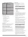
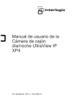
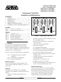
This practice provides installation and operation
procedures for an ADTRAN Total Access 1500
System Controller Unit (SCU), common modules List
1, List 2, and List 3. Figure 1 shows the Total Access
1500 SCU, List 1, List 2, and List 3.
The SCU comes in the following three configurations:
• List 1 – No Mechanized Loop Test (MLT)
capability.
• List 2 – Central Office Terminal MLT
• List 3 – Remote Terminal MLT
Revision History
This is the second release of this document. This
version includes updates describing TL1 over X.25
and TCP/IP.
Features
The Total Access 1500 SCU, P/Ns 1180008L1,
1180008L2, and 1180008L3, includes the following
features:
• Control all common equipment and access
modules
61180008L1-5B
A
D
M
I
N
T
E
S
T
A
D
M
I
N
T
E
S
T
MJR
HST
MJR
HST
MNR
MLT
BSY
MNR
MLT
BSY
RMT
RMT
RMT
ACO
ACO
ACO
List 1
Compliance Codes ................................... 2
Front Panel Description ........................... 3
DCE Pin Assignments .............................. 3
X.25 Pin Assignments .............................. 4
Detailed SCU Specifications ................... 9
1180008L3
1180008L2
T
E
S
T
MJR
SCU RT
SCU COT
1180008L1
List 2
List 3
Figure 1. Total Access 1500 SCU
• Mechanized Loop Test (MLT) capability (L2 and
L3 used together only)
• Provide VT100 craft interface via front panel
DB-9 connector
• Alarm Cut Off (ACO) pushbutton
• Bank status indicators
• Test equipment timing output
• Meet NEBS Level 3 and UL 1950 requirements
• Provides alarm status to NMA and/or SNMP
• Provides internal PAD for X.25 network
• Software can be upgraded while in field without
affecting service
• Operates in Host or Client mode for RS-485
chaining applications
• Supports TL1 over TCP/IP or X.25
• Supports menu access over Telnet
• L2 and L3 monitor primary and secondary power
feeds. L1 does not monitor power feeds.
General Description
The Total Access 1500 SCU is a common module,
plug-in unit designed for the Total Access 1500. The
SCU provides all control functions for the Total
Access 1500 common units and all the individual
access modules. The SCU manages all network
related functions and communicates externally
Trademarks: AnySection
brand names
and product names included
61180008L1-5,
Issue in2this document are
trademarks, registered trademarks, or trade names of their respective holders.
1
through RS-232, RS-485, and Ethernet interfaces. The
SCU manages the Mechanized Loop Test (MLT)
feature and controls the activation/deactivation relays.
Compliance
Table 1 shows the Compliance Codes for the Total
Access 1500 SCU. The SCU complies with the
requirements covered under UL 1950 and is intended
to be installed in Restricted Access Areas only and in
equipment with a Type “B” or “E” enclosure.
NOTE
At this point in the installation, power should
not be applied to the Total Access 1500 shelf.
Table 1. Compliance Codes
Code
Input
Output
Power Code (PC)
C
C
Telecommunication Code (TC)
-
X
Installation Code (IC)
A
-
This device complies with Part 15 of the FCC rules.
Operation is subject to the following two conditions:
1. This device may not cause harmful interference.
2. This device must accept any interference
received, including interference that may cause
undesired operation.
Changes or modifications not expressly approved by
ADTRAN could void the user’s authority to operate
this equipment.
2. INSTALLATION
C A U T I O N !
SUBJECT TO ELECTROSTATIC DAMAGE
OR DECREASE IN RELIABILITY.
HANDLING PRECAUTIONS REQUIRED.
After unpacking the unit, inspect it for damage. If
damaged, file a claim with the carrier. Then contact
ADTRAN Customer Service. Refer to the Warranty
and Customer Service section of this practice.
Electronic modules can be damaged by static
electrical discharge. Before handling modules, wear
an antistatic discharge wrist strap to prevent damage
to electronic components. Place modules in antistatic
packing material when transporting or storing.
2
The Total Access 1500 SCU plugs directly into the
SCU slot in the common module area of the Total
Access 1500 chassis.
WARNING
The Total Access 1500 SCU can only be inserted
into the third slot of the shelf. Attempting to
insert the SCU in any other slot may damage the
SCU and/or the backplane.
To Install the Total Access 1500 SCU, perform the
following steps:
1. Pull the latch/ejector on the bottom of the SCU
front panel from its closed position.
2. Hold the unit by the front panel while supporting
the bottom side.
2. Align the card edges to the guide grooves for the
SCU slot.
3. Gently, but firmly, push the SCU into the third
slot on the shelf. Simultaneous thumb pressure at
the top and bottom of the SCU will ensure a good
seat of the SCU pins into the backplane
connector.
4. Lock the unit in place by pressing down the
locking lever.
All power, ground and administrative wiring should
now be completed on the Total Access 1500 shelf, and
an SCU should be installed in the shelf. The next
procedure is to apply power to the shelf with an SCU
in place, and ensure that the SCU properly powers up
and successfully completes its power-on self-test
routine. To verify that the SCU completes its self-test
routine perform the following steps:
1. Insert a fuse into the fuse and alarm panel serving
either the A or B power feeds to the Total Access
1500 shelf. The fuse should be selected with an
amperage appropriate for the intended use of the
Total Access shelf.
2. Verify that the SCU power-on self-test routine is
successfully completed. The LEDs will all
simultaneously flash, then the ACO, HST, and
MLT BSY LEDs will flash four times staying on
the last time. Once these LEDs turn off, the front
panel will represent the true status of the SCU.
This may take more than 1 minute.
Section 61180008L1-5, Issue 2
61180008L1-5B
Craft Port
The SCU provides an RS-232 serial asynchronous
craft access port. Physical access is attained by
connecting a male-ended DB-9 cable to the female
DB-9 connector on the SCU front panel. This port can
operate at various baud rates and is limited to 8-bit
asynchronous data with no parity, one stop bit.
Minimal 3-wire functionality (pins 2, 3, and 5) is also
accommodated. This port operates as a DCE; pin
assignments are detailed in Table 3.
3. This constitutes a complete and successful
power-on test.
NOTE
Once successfully powered up, if only A or B
power is supplied, the SCU will reflect a MIN
alarm for A (or B) power failure.
3. OPERATION
Power
The Total Access backplane delivers two -48 VDC
buses to the SCU. The SCU operates with both or
either -48 VDC buses active.
Table 3. DCE Pin Assignments
Pin Number
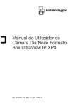
Front Panel Indicators
See Table 2 for a description of front panel LEDs and
buttons.
User Interface
Since the SCU is the user access point to the shelf and
its access modules, it must support a number of user
physical interfaces and service the shelf’s
communication buses. The SCU supports a craft port,
X.25 port, and an Ethernet port.
Function
2
Transmit Data from DCE
3
Receive Data into DCE
4
DTR (Data Terminal Ready)
5
Signal Ground
X.25 Port
The SCU supports synchronous RS-232 compatible
serial interface to be used in conjunction with an X.25
network. The unit includes PAD functions onboard so
an external PAD is not required for operation with the
X.25 network. Physical access uses a 25-pin female
DB-25 connector (J34) on the rear of the Total Access
1500 shelf. The X.25 connector pin assignments are
detailed in Table 4.
Table 2. Front Panel Description
SCU COT
1180008L2
T
E
S
T
A
D
M
I
N
MJR
HST
MNR
MLT
BSY
RMT
LED
Color
MJR
Off
Red
No Major alarm condition detected.
Major alarm active (Red Alarm)
MNR
Off
Yellow
No Minor alarm condition detected.
Minor alarm active (Yellow Alarm)
RMT
Off
Yellow
No Remote or Auxiliary alarm condition detected.
Remote or Auxiliary alarm active
ACO
Off
Green
ACO switch not activated
ACO switch activated
HST
Off
Green
SCU is client for cluster group
SCU is host for cluster group
MLT BSY
Off
Green
No MLT test is active
MLT test is active
ACO
Description
Switch
ACO
Switch
61180008L1-5B
Description
Press to disable any audible alarms only. Any active visual alarms will
remain active.
Section 61180008L1-5, Issue 2
3
Table 4. X.25 Pin Assignments
Pin Number
Function
1
Frame Ground (FG)
2
Tramsmit Data (TD) from DTE
3
Receive Data (RD) into DTE
4
Request To Send (RTS)
5
Clear To Send (CTS)
6
Data Set Ready (DSR)
7
Signal Ground (SG)
8
Data Carrier Detect (DCD)
15
Tramsmit Clock
17
Receive Clock
20
Data Terminal Ready (DTR)
22
Ring Indicator (RI)
This port operates as a DTE and is configured for the
following settings:
• 1-way in or 2-way operation
• Up to four SVCs
• Up to 64 kbps (synchronous)
• Packet size: 128 bytes
• Packet window: 2
• n2 retry limit: 3
• T1 ACK timer: 20 seconds
• T3 time out: 3 seconds
• k window size: 2
Ethernet Port
The SCU provides an SNMP interface via a standard
Ethernet 10BaseT connector (J33) located on the
backplane of the Total Access 1500 shelf.
Connect and Logon to System
There are two ways to connect and logon to the
system: via the VT100 craft/admin interface or a
Telnet session.
Total Access shelf management and provisioning is
facilitated by a series of intuitive menus that are
accessible on a computer screen. These menus are
available through either a VT100 terminal session or a
Telnet session.
VT100 Terminal
To connect either a terminal or a PC emulating a
terminal to the craft port:
1. Set the parameters of the VT100 terminal to:
• 9600 baud rate
NOTE
The SCU craft port is defaulted to 9600 but has
additional available baud rate of 38400.
•
•
•
•
8 data bits
No parity
1 stop bit
No flow control
2. When connecting a terminal to the craft port and
the terminal has a parallel setting, disable it and
use serial. When connecting a PC emulating a
VT100 terminal to the craft port, set the PC for
direct connect (as opposed to dial-up
connection).
3. When you are using the front craft port, use a
serial cable with a male DB-9 connector on the
Total Access end.
4. Plug the male end of the data cable into the Total
Access shelf. Make connection to the VT100
terminal as appropriate for your equipment.
5. To logon to the Total Access system, press any
key. When password Authentication is enabled,
the cursor will be placed at the Account Name
field, waiting for an Account Name to be input.
NOTE
The default account name is “user” and the
default password is “password”.
6. At the Account Name field, input the Account
Name for the Total Access shelf, then press
ENTER. The cursor will be placed at the
Password field, waiting for a Password.
7. At the Password field, enter the Password for the
Total Access System, and press ENTER.
8. Upon entering the correct password, the Total
Access main menu is presented on the screen.
The Total Access menu system can now be
accessed.
4
Section 61180008L1-5, Issue 2
61180008L1-5B
Telnet
The SCU will support four concurrent Telnet sessions.
Telnet is supported via the Ethernet interface.
To use Telnet to communicate with the SCU, use the
following steps:
1. Set the proper IP Address for the connection
method of choice via the provisioning menu. For
this procedure, refer to the following page of this
practice.
2. Connect to the Ethernet Interface on the
backplane of the Total Access 1500 shelf.
NOTE
The IP Address, Subnet Mask and Gateway are
in the form XXX.XXX.XXX.XXX, with the
XXX’s representing 1, 2 or 3 digit decimal
numbers from 0 to 255.
3. Enter a valid IP address, and press ENTER.
4. From the Managemen Configuration menu,
select option 2, IP Subnet Mask, and press
ENTER.
5. Enter a valid Subnet Mask, and press ENTER.
3. A successful Telnet connection is established
when the following appears on the screen:
/* enter ‘MENUS;’ to obtain menus (characters
will not echo) */
OK 0
<
4. A TL1 session may be activated at this time or to
logon to the Total Access Menu System, enter
‘MENUS;’. If Password authentication is
enabled, enter the Account Name for the Total
Access shelf, and press ENTER. The cursor will
then be placed at the Password field, waiting for
a password.
5. At the Password field, enter the Password for the
Total Access System, and press ENTER.
6. Upon entering the correct password, the Total
Access main menu is presented on the screen.
This signifies a successful logon.
Provision the Ethernet Interface Settings
If the Total Access 1500 shelf is to be connected to an
Ethernet network for Telnet, TFTP or SNMP
Management, the IP Address, Subnet Mask, and
Default Gateway must be set for the shelf to
communicate with the network.
To set the IP Address, Subnet Mask, and Gateway:
1. From the System Controller main menu, select
option 5, Management Configuration, and press
ENTER.
2. From the Management Configuration menu,
select option 1, IP Address, and press ENTER.
61180008L1-5B
6. From the Management Configuration menu,
select option 3, IP Default Gateway, and press
ENTER.
7. Enter a valid Default Gateway, and press
ENTER.
8. From the Management Configuration menu,
select option 4, Telnet Port Number, and press
ENTER.
9. Enter the port to connect to when performing
TL1 over TCP/IP. This is set to 2000 as a
default.
Menuing System
The ADTRAN Total Access SCU provides a menuing
system for the Total Access shelf. All system-related
menus are controlled by the SCU as well as some of
the access modules menus. Other access modules have
their own user menu structure supported by the
module.
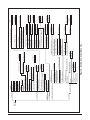
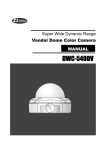
Menu Structure
The menu structure for the SCU is a layered menu
tree. Each menu level consists of submenus and/or
menu items. Some menu items are restricted to certain
user accounts. The SCU supports Read-Write and
Read-Only accounts. Each of these accounts may also
be given Test or Admin privileges. The Admin
privileges allow the user to change all provisionable
settings as well as network configuration settings that
are not accessible to Read-Write and Read-Only
accounts. Examples include SNMP provisioning, TL1
provisioning, Date/Time settings, password
administration, and software downloads. The
Read-Write account allows the standard provisioning
settings to be changed. The Read-Only account allows
Section 61180008L1-5, Issue 2
5
the user to view all provisioning settings, alarms, and
statistics. An account with Test privileges will also
allow the account to perform tests. Figure 2
illustrates the menu structure of the SCU.
Submenus are elements that move the user down to
the next menu level. Menu items are elements which
allow the user to make changes to the current SCU
settings. There are two different types of menu items:
read-only and read-write.
A read-only menu item displays information that can
not be changed, such as the status of the SCU. A
read-write menu item displays information that when
selected can be changed, such as the baud rate of the
admin port.
Intersystem Communication (RS-485)
The ADTRAN Total Access 1500 SCU supports
communication with other Total Access 1500 systems
over a shared, twisted-pair, half-duplex, RS-485 link.
The SCU from each system is connected in parallel on
this bus. Pin A should be connected to pin A, and Pin
B should be connected to Pin B, so each shelf is in
parallel. One SCU acts as the master controller and
all others function as slaves. Physical access is
attained by way of wire-wrap posts (P12) on the rear
of the Total Access 1500 Shelf. Up to 32 shelves may
be clustered together via the RS-485 bus.
To set up RS-485 chaining, perform the following:
1. Give the first SCU in the chain a unique Target
ID (TID).
2. Enable RS-485 Interface.
3. Set Interbank Communication Mode to Host.
4. Give the next SCU in the chain a unique Target
ID (TID).
Setting the Target ID (TID)
A unique Target ID (TID) must be given to each shelf
of a chained RS-485 cluster. To set the Target ID
(TID) in the Total Access 1500 SCU, perform the
following:
1. Logon to the system.
2. From the Total Access 1500 main menu, select
option 1, System Controller, and press ENTER.
3. From the System Controller menu, select option
2, Provisioning, and press ENTER.
4. From the Provisioning menu, select option 6,
Target ID (TID), and press ENTER.
5. Enter the appropriate Target ID and press
ENTER.
NOTE
The Target ID (TID) may consist of up to 20
characters. The first character must be a letter.
The remaining characters minus the last character
may be alphanumeric or a hyphen. The last
character must be alphanumeric.
An example of a Target ID (TID) follows:
HTVLALEXD01
Where:
HTVL
AL
EX
D
01
5. Enable RS-485 Interface.
designates the city
designates the state
identifies the Central office or remote
terminal
identifies the equipment type ("D" is
administrative equipment)
identifies the piece of equipment of
that type at the CO
6. Set Interbank Communication Mode to Client.
Repeat steps 4-6 until up to 32 shelves have been
chained.
6
Section 61180008L1-5, Issue 2
61180008L1-5B
61180008L1-5B
Section 61180008L1-5, Issue 2
7
6. Security
Enter Value
Enter Value
2. SCU Reset
Usernames (1-16)
2. 38400
1. 9600
2. Enabled
5. Admin
Enter New Password
Enter New User Name
1. Disabled
10. LIU Configuration
9. PSU Configuration
8. Re-Map Interface Indices
7. SNMP Trap Hosts
6. System Location
5. System Name
4. System Contact
2. Read/Write
Trap Host 1-8
3. Read-Write Community Name
2. Read-Only Community Name
1. SNMP Authentication Traps
1. Read-Only
2. Enabled
1. Disabled
2. Enabled
1. Disabled
2. Status
1. IP Address
Enter Value
2. Enabled
1. Disabled
2. Single PSU
1. Dual PSU
2. Cancel
1. Erase SCU
2. Online LIU
1. SCU
2. Disabled
1. Enabled
Enter IP Address
2. Single LIU
1. Dual LIU
2. Minor
3. Major
1. Disabled
2. Enabled
1. Disabled
2. Enabled
1. Disabled
Enter New Checksum
2. D4 Conventional
1. T1 Mapping
8. SLC-96 Pwr/Misc Alm (COT Only)
7. ACO Alarm
6. RMT Alarm
5. AUX2 Alarm
4. AUX1 Alarm
3. Ringer Alarms
2. Log MLT Alarms
1. Alarm Relay Mapping
5. Reset the Y-Modem Destination
4. Compute Checksum and Store
3. Modify Checksum
2. Start Y-Modem Upload
1. Select Y-Modem Upload Destination
Figure 2. System Controller Menu Tree
6. Delete This User
2. Enabled
1. Disabled
Enter Value (1...60)
2. Enabled
1. Disabled
Enter Value (1024 .. 9999)
Enter Value
2. MLT Mode
1. MTA Mode
2. Host
1. Client
4. Test
3. R/W
2. Password
1. User Name
6. SNMP Configuration
5. TCP/IP Port Number
4. TELNET Port Number
3. IP Default Gateway
2. IP Subnet Mask
1. IP Address
1. Force LIU Failover
11. Craft Port Baud Rate
10. Test Access Mode
9. Y-Modem Application
2. Local
1. None
2. Auto-Logout Time
1. Terminal Auto-Logout
Enter New Password
8. Interbank Communication Mode
7. RS-485 Interface
6. Target ID (TID)
5. Password
4. Password Authentification
3. Terminal Auto-Logout
2. Time
1. Date
MAC Address
Software Revision
Product Revision
CLEI Code
Part Number
Unit Name
5. Management Configuration
4. Alarms
3. Test
2. Provisioning
1. Configuration
Alarm Processing
The SCU monitors the status of each line card and
provides necessary alarm processing to determine the
overall alarm state of the system.
Configuring Alarms
To configure alarms the user will need to perform the
following:
Alarm Outputs
The SCU determines alarm states and reports these
results via onboard alarm interfaces and through
active user access channels. Each onboard alarm
interface consists of Form-C relay contacts to provide
Common (COM), Normally Open (NO), and
Normally Closed (NC) functionality. Physical access
to the relay contacts is attained by way of wire-wrap
posts per alarm function. These posts are located on
the rear panel of the Total Access 1500 shelf. The
following alarm outputs are supported:
2. From the Total Access 1500 main menu, select
option 1, System Controller, and press ENTER.
•
•
•
•
Alarm
Major Audible
Minor Audible
Major Visual
Minor Visual
Wire-wrap Header
MAJ-A
MIN-A
MAJ-V
MIN-V
The SCU provides front panel LEDs (See Table 2) to
indicate the status of the shelf and Alarm Cut Off
(ACO) state.
Alarm Inputs
The SCU supports external alarm, status, or control
inputs. Circuitry on the SCU accepts a -48V signal as
an active state. Physical access to these inputs is
attained by way of two wire-wrap posts per input
function located on the rear panel of the Total Access
1500 shelf. The following alarm inputs are supported:
•
•
•
•
Alarm
Auxiliary 1
Auxiliary 2
Alarm Cut Off
Remote
Wire-wrap Header
AUX 1
AUX 2
AUX 3
AUX 4
NOTE
The front panel mounted ACO switch is used to
cut off an alarm.
8
1. Logon to the system.
3. From the System Controller menu, select option
4, Alarms, and press ENTER.
4. Provision the alarms as desired.
The following items may be configured:
• Alarm Relay Mapping – allows the user to select
T1 or D4 alarm relay mapping
• Log MLT Alarms – enables/disables the logging
of MLT alarms
• Ringer Alarms – enables/disables ringer alarms
• AUX1 Alarm – enables/disables AUX1 alarm
input
• AUX2 Alarm – enables/disables AUX2 alarm
input
• RMT Alarm – enables/disables RMT alarm input
• Primary Power Alarm – enables/disables alarm
condition associated with having primary power
feed removed
• Secondary Power Alarm – enables/disables alarm
condition associated with having secondary
power feed removed
• PSU Configuration – choose single or dual PSU
according to whether redundant equipment is
installed in the Total Access 1500 chassis
• LIU Configuration – choose single or dual LIU
according to whether redundant equipment is
installed in the Total Access 1500 chassis
Section 61180008L1-5, Issue 2
61180008L1-5B
4. MAINTENANCE
The SCU requires no routine maintenance to operate
properly. Conduct tests and maintenance for the
specific plug-ins in accordance with the
recommendations and procedures prescribed by the
manufacturer of each specific plug-in. ADTRAN
cautions against performing major repairs in the field.
5. PRODUCT SPECIFICATIONS
Product specifications for the ADTRAN Total Access
SCU are detailed in Table 5.
Repair services may be obtained by returning the
defective unit to the ADTRAN Customer Service
RMA Department. Refer to Warranty and Customer
Service section for more information.
Table 5. Detailed SCU Specifications
General
Front Panel: Craft Interface, DB-9 Connector (female)
LEDs: MJR
MNR
RMT
HST
MLT BSY
ACO
Switches: ACO Pushbutton Switch
Ethernet: 10BaseT
Shelf life for non-volatile memory storage: 10 years minimum
Power
Current Draw: 0.088 A maximum @ -48 V
Physical
Dimensions: 3.125 in. H x 1.54 in. W x 10.1 in. D
Weight: < 1 lb.
Environment
Operating Temperature (Standard): -40ºC to +65ºC
Storage Temperature: -40ºC to +85ºC
Relative Humidity: 95% maximum @ 50ºC, noncondensing
Heat Dissipation: 4.24 watts maximum
Compliance
UL 1950
NEBS Level 3
GR-1089-CORE
Part Number
Total Access 1500 System Controller Unit (SCU) Common 1180008L1
Module
61180008L1-5B
Section 61180008L1-5, Issue 2
9
6. WARRANTY AND CUSTOMER SERVICE
ADTRAN will replace or repair this product within
ten (10) years from the date of shipment if it does not
meet its published specifications or fails while in
service. Refer to ADTRAN U.S. and Canada Carrier
Networks Equipment Warranty, Document
60000087-10.
Contact Customer and Product Service (CAPS) prior
to returning equipment to ADTRAN.
For service, CAPS requests, or further information,
contact one of the following numbers:
ADTRAN Sales
Pricing/Availability
(800) 827-0807
ADTRAN Technical Support
Pre-sales Applications/Post-sales Technical
Assistance
(800) 726-8663
Standard hours: Monday-Friday, 7 a.m. - 7 p.m. CST
Emergency hours: 7 days/week, 24 hours/day
ADTRAN Repair/CAPS
Return for Repair/Upgrade
(256) 963-8722
Repair and Return Address
ADTRAN, Inc.
CAPS Department
901 Explorer Boulevard
Huntsville, Alabama 35806-2807
10
Section 61180008L1-5, Issue 2
61180008L1-5B