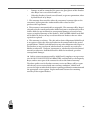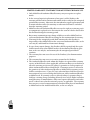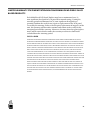
1
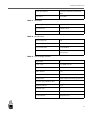
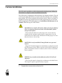
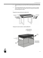
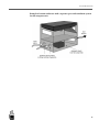
MultiTaction Cell 55"
MT550 User Manual
(v.1.1)
Notice to Users
This user manual is intented for the owners and operators of MultiTouch MultiTaction Cell products. It contains guidelines for the proper usage of the products. Information in this manual is subject to change without prior notice to
product owners. For the latest product details and guidelines please visit the
product website.
Copyright © 2011 Multitouch. All rights reserved.
MultiTaction and MultiTouch Cornerstone are trademarks of Multitouch. All other trademarks are the property of their respective owners.
NOTE:
Trademarks
MultiTaction and MultiTouch Cornerstone are trademarks of Multitouch.
All other trademarks are the property of their respective owners.
Safety Information
Read carefully through and comprehend all the given safety information before
installing or using the product. Follow instructions found on this manual and
marked on the MultiTaction Cell. Take careful notice of all the warnings and
safety related instructions to install and use the product safely.
Safety Signal Word
Explanation
DANGER
Indicates a hazard with a high level of risk which,
if not avoided, will result in death or serious injury
AND / OR property damage.
WARNING
Indicates a hazard with a medium level of risk
which, if not avoided, could result in death or
serious injury AND / OR property damage.
CAUTION
Indicates a hazard with a low level of risk which, if
not avoided, could result in minor or moderate
injury AND / OR property damage.
NOTICE
Indicates important information.
Regulatory information
European Union Directive on Restriction of Hazardous Substances (RoHS)
This MultiTaction Cell complies with the following regulatory standards:
• RoHS
• EN 55022
• EN 55024
• IEC 61000-3-2
• IEC 61000-3-3
• IEC 62471
• IEC60950:2005+A1:2009
More information on the complience can be acquired from Multitouch by
delivering the S/N of the MultiTaction Cell in question.
Disposal Guidelines
The Cell complies with the European RoHS -directive. Please consult local
authorities and professionals when planning to dispose the Cell.
Table of Contents
Introduction .................................................................................................................... ........ 1
Device Overview .............................................................................................................. ........ 2
Dimensions .......................................................................................................................... ......... 3
Connection Panel ................................................................................................................. ......... 4
Warning Labels ................................................................................................................... ......... 5
Technical Specifications ...................................................................................................... ......... 6
Box Contents .................................................................................................................... ........ 10
Unpacking the Cell .......................................................................................................... ........ 11
Installing the Cell ............................................................................................................. ........ 13
Proper Environment ............................................................................................................ ......... 13
Ventilation and Heat Control ............................................................................................ ......... 14
VESA Mount Installation.................................................................................................... ......... 15
Custom Installation ............................................................................................................. ......... 17
Desk Stand Installation ....................................................................................................... ......... 20
Multi-Cell Installation ......................................................................................................... ......... 22
Display wall installations....... ............................................................................................. ......... 23
Connecting the Cell .......................................................................................................... ........ 26
Normal Operating Conditions.......................................................................................... ........ 27
Guidelines for Maximum Performance ........................................................................... ........ 28
Software Setup ................................................................................................................. ........ 29
Operations on the MultiTaction Cell ................................................................................ ......... 29
Operations on the Application PC .................................................................................... ......... 30
Finalizing the Setup ............................................................................................................. ......... 31
More information ................................................................................................................ ......... 31
Computer Recommendations ............................................................................................ ......... 32
Installation of Cornerstone ................................................................................................. ......... 33
Calibration ........................................................................................................................... ......... 34
Tuning of the Tracking Parameters.................................................................. .........34
Finger Tracking ................................................................................................ .........34
Marker Tracking .............................................................................................. .........34
Automatic Geometry calibration 34
On-line Resources ................................................................................................................ ......... 35
Maintenance and Cleaning............................................................................................... ........ 36
Warranty Information ..................................................................................................... ........ 37
INTRODUCTION
Introduction
MultiTaction Cells are multi-touch, modular LCD displays intended for (but in
no way limited to) retail businesses, advertising, exhibitions, museums, education, and design installations. ‘MultiTaction’ means that Cells can track and
react to several people interacting with them simultaneously. Moreover, the
system tracks a person’s hands instead of points of contact only, further
enhancing interactive possibilities.
The LCD displays deliver Full HD picture quality, have a long life-span, and
need hardly any maintenance. ‘Modular’ means that Cells can be easily
connected to each other to create a single large display array showing interactive
content split into the various screens, while reacting to multiple users’ touch.
The system welcomes customization. Work on Linux, Mac, or Windows environments, and create your own tailored apps through the MultiTouch Cornerstone SDK or many other supported methods.
This manual contains the installing and operating instructions for
MultiTaction Cell 55”.
1
DEVICE OVERVIEW
Device Overview
MultiTaction is an innovative way to build an integrated multi-touch LCD
display. The front glass and LCD package is tuned to allow the integrated optical
imaging system to work effectively through it. Imaging logic and processing
power are embedded in the display unit. The illustration below shows the main
technologies used in MultiTaction.
2
DIMENSIONS
Dimensions
The Cell enclosure holds the following dimensions:
3
CONNECTION PANEL
Connection Panel
Connection panel of the Cell is located at the back of the device. It contains
power switch and the following sockets for connecting the Cell to approriate
devices and to the mains.
Socket
Purpouse
3 USB Sockets
USB sockets are intended for peripherals of
the Cell (for example keyboard and mouse)
USB B
For control input
Ethernet
For control input
DisplayPort
Display signal input
DVI-D
Display signal input
Mains
Power connection to the mains supply
4
WARNING LABELS
Warning Labels
The following warning labels can be found on the Cell:
•
CLASS 1 LED PRODUCT (IEC 60825-1 A2:2001) -label attached to the
back of the enclosure
•
CLASS 2 LED RADIATION -warning label (IEC 60825-1 A2:2001)
attached to metal structure within the enclosure of the Cell.
5
TECHNICAL SPECIFICATIONS
Technical Specifications
Table 1: Display Specification
Display Technology
TFT LCD
Display Size
55" 16:9 Wide
Native Resolution
Full HD 1920 x 1080
Display Colors
16.7 million
Display Active Area
1209 x 680 mm
Pixel Pitch
0.63 x 0.63 mm
Pixel Response Time
8ms grey to grey
Brightness
250 cd/m2
Contrast Ratio
4000:1 typical
Picture Frame Rate
60 Hz
Backlight
White LED Matrix Array
Viewing Angle
178
Table 2: Touch Sensing Hardware
Touch technology
Computer Vision Through Screen
Tracking Speed
Up to 200 fps
IR Source & cameras
Integrated Backlight Emitter Camera
modules
IR Wavelength
850 nm
Table 3: Touch Surface
Display Safety Glass
Tempered 4 mm Optiwhite Glass
covering whole front surface
Table 4: Interfaces
Video Input
DVI-D, DisplayPort
6
TECHNICAL SPECIFICATIONS
Control Input
USB B, Ethernet
Auxiliary input for keyboard, mouse
and extra memory
USB A
Power Connector
IEC C14
Table 5: Electrical Specifications
Power Supply
100-240 VAC 50/60 Hz
Power Consumption
450W
Table 6: Touch Details
Tracking Software
Embedded MultiTaction Extensible
Hybrid Tracking Engine
Touch Input Types
Single finger, multiple fingers, single
hand, multiple hands and users,
objects with optical markers. Click,
hold and drag.
Hand Recognition
Each finger identified to certain hand
Object Recognition
Supported with 2D fiducial markers
Number of Simultaneous Touch
Inputs
Unlimited
Number of Simultaneous Users
Unlimited (separate hands)
Positional accuracy
2mm, directional compensation
Relative accuracy
Sub-pixel accuracy
Touch Latency
10 ms typical. Measured from touch to
processed tracking data output.
Overall latency is greater and depends
on the computer, operating system,
and application used.
Tracking Data Outputs / APIs
Multi-Format Tracking Ouput: Low
level C++, TUIO, XML stream,
Windows 7 Touch
Operating System Support
Windows 7, Linux, Mac OS X
7
TECHNICAL SPECIFICATIONS
Development Environment Support
Most major programming languages
and environments (MS surface 2 SDK,
TUIO-compatible systems). See
MultiTouch Cornerstone for further
details.
Software Development Kit
Cornerstone SDK available for
C++/OpenGL (Windows 7, Linux,
Mac OS X)
Stackability
Up to 24 Cells can be connected to
run a single multitouch application.
Table 7: Enviroment Specifications
Operating Temperature
0 to +35 degrees C
Storage Temperature
-10 to +60 degrees C (Allow at least
two hours for temperature
normalization before switching on the
unit.)
Relative Humidity
Non-condensing 80%
Table 8: Dimensions and Weight
Physical Dimensions
1242 x 713 x 199 mm
Bezel width
16 mm (bottom & sides), 17 mm (top)
Weight
40 kg (90 lbs)
Color
Black
Table 9: Display Mounting
VESA Mount
800 x 400 mm, M8 screws
Mounting positions
Vertical, Horizontal, Angled position,
Table position, Display Array (2-24
units), Symmetric or asymmetric
layouts
Table 10: Cooling
Cooling system
Forced Air
8
TECHNICAL SPECIFICATIONS
Convection method
Low Noise Variable Speed Internal
Fans
Noise Level
15-25 dBa
Table 11: Ventilation
Air passing through the Cell:
Typical amount
220 m3 / hour
Maximum amount
250 m3 / hour
Table 12: Miscellaneous
Agency Approvals
CE
RoHS Compliant
Yes
Expected Life-time
Over 60,000 h
Warranty
1 year limited (See warranty details in
this manual)
Table 13: Sales Package Contents
Display Unit
1
Power Cords
5 m, EUR, US, GB
Digital Video Cable
DVI-D 5 m
USB A-B Cable
5m
Cat5e Ethernet Cable
5m
Display Stand
Table stand for landscape/portrait use
Protective/autocalibration sheet
1
Alignment rail bits
4 pcs
Warranty Card
1
Quick Start Guide
1
Product Manual
English version
9
BOX CONTENTS
Box Contents
MultiTaction Cell product box contains the following items:
•
MultiTaction Cell
•
AC Power Cords (US, GB and German)
•
DVI-D Monitor cable
•
USB cable
•
Ethernet cable
•
Production Test Report
•
User guide
•
Alignment rail bits (4 pcs)
Carefully check that you have received all the items before proceeding with the
installation of the Cell. If your product box is missing items, please contact your
dealer.
10
UNPACKING THE CELL
Unpacking the Cell
Follow these steps to unpack the Cell from its shipping box:
The Cell is delivered in a specially designed container to secure it during the
transportation. Place the container on a clean floor. Make sure to have enough
space around the container to remove the Cell and place it to the desired location. The Cell is to be removed by two persons, one lifting from each side.
TASK
1.
Bend all the metal tabs on the bottom of the box (1).
2.
Remove the container top by lifting it up (2).
11
UNPACKING THE CELL
3.
Remove the protective padding on the top of the Cell (1).
4.
Remove the Cell from the container with help from another person, one
lifting from each side (2).
12
INSTALLING THE CELL
PROPER ENVIRONMENT
Installing the Cell
The MultiTaction Cell must be installed before use. Follow one of the four
installation guidelines:
1)
VESA Mount Installation
2)
Custom Install
3)
Multi-Cell Installation
4)
Desk Stand Installation
Before installing ensure that the installation and usage environment is suitable
the the MultiTaction Cell.
Proper Environment
Choose a well-ventilated, cool space for setting up the display.
CAUTION: Infrared sources (like halogen spots) may harmfully
interfere with the tracking sensors.
• Keep the Cell away from strong spot-light areas.
CAUTION: Intense sunlight can damage the display.
• Place the Cell in a space where intense sunlight does not hit the
display area (front panel).
13
VENTILATION AND HEAT CONTROL
Ventilation and Heat Control
Controlling the heat exposure of the Cell affects the lifetime and operating
safety of the device. To ensure proper heat control review the following checklist.
Table 14: Heat Control Checklist
Heat control target
Correct status
Ventilation
The Cell is installed in a well-ventilated
environment and in a well-ventilated
enclosure (if enclosure is used). The device
is not covered with clothes, papers, props or
other materials which can prevent the
proper ventilation of the device.
Operating temperature
Temperature is between the limits specified
on the Normal Operating Conditions.
External factors
There are no external factors heating the
Cell above the temperature limits. External
factors can include for example direct
sunlight, spotlights or other heat emitting
devices.
Installation distances
The minimum safety distances described on
the proper section of the chapter Installing
the Cell are followed.
14
VESA MOUNT INSTALLATION
VESA Mount Installation
The MultiTaction Cell complies with the VESA Mounting Interface Standard
(MIS-F) by having four screw holes of the VESA M8 MIS-F 800, 400, 8 type on
its back panel and can be installed to VESA Mounts.
Install the Cell to any pedestal or wall mount that conforms to the VESA
Mounting Interface Standard.
TASK
1.
Locate the Standard M8 VESA Mount Screw holes on the back panel of the
Cell.
CAUTION: Heat build-up reduces the systems' life and can cause
hardware failure.
• Make sure that the cooling and air ventilation properties of the
installation location meet the requirements of the Cell.
15
VESA MOUNT INSTALLATION
Keep the ventilation slots free of blockages at all times. Leave enough space
behind the Cell to allow proper air circulation and cooling between the display
and walls or panels:
Installation type
Safe distance between the Cell and
walls/panels
Single Cell
at least 10 cm (4 inches)
Multi-Cell
at least 15 cm (6 inches)
2.
Select the VESA Mount installation location and install the Cell
according to the VESA Mounting Interface Standard.
16
CUSTOM INSTALLATION
Custom Installation
The Cell can be installed as a table in horizontal or tilted position. Follow the
instructions to complete custom installation of the Cell.
The Cell features an alignment rail found on the top, bottom and sides. The rail
can be used to align the Cell into a custom enclosure with M5 screws and alignment rail bits. The Cell is attached to the enclosure by the VESA screw holes. A
simplified custom setup would consist of sturdy supporting legs on each side,
firmly wrapping the Cell and keeping it at the minimum safety distance 15 cm
(6 inches) from the top of a stable surface.
DANGER: Never install a Cell inside a fully enclosed space! Risk of
device overheating, which can lead to critical hardware failure
and personal injuries.
• Ensure that the dimensions and setup of the custom enclosure
comply with the minimum safety distance requirement 15 cm (6
inches) above the stable surface and that the Cell has proper air ventilation (cool air in, hot air out).
CAUTION: Loosely installed Cell may fall and cause personal
injuries.
• Align the Cell with the alignment rail and the according bits. Attach
the Cell properly by the VESA screw holes. If the Cell is installed in a
public environment check the condition of the enclosure and attachments regularly.
NOTICE: Any unauthorized modification of the Cell will void
warranty.
• The front glass may be changed in coordination with MultiTouch.
This requires explicit, signed warranty exception.
TASK
1.
Prepare the custom enclosure for the Cell.
17
CUSTOM INSTALLATION
2.
Locate the M8 type screw holes (VESA) and the alignment rail from the
Cell.
3.
Firmly attach the Cell to the custom enclosure. Do this by using M8
screws and the VESA screw holes of the Cell. Align the Cell with the
included alignment rail bits.
Example of custom table with installed Cell
Example of custom enclosure with installed Cell
18
CUSTOM INSTALLATION
Example of custom enclosure with a separate space and ventilation system
for the computer unit
19
DESK STAND INSTALLATION
Desk Stand Installation
The MultiTaction Cell comes with a pair of desk stands. Desk stands are
intended for safe and stable installation when the Cell is to be located horizontally or vertically on a sturdy desk or table.
CAUTION: Using a desk with too light structure, installing the
desk stands incorrectly or into an incorrect position causes a risk of
the Cell tipping over, property damage and personal injuries.
• To avoid the risk choose a desk with a heavy enough structure for
the installation, install the desk stands according to this manual and
ensure that desk will not tip after the installation.
TASK
1.
Choose a sturdy desk for the installation. Ensure the desk can bear the
weight load of the Cell (45 kg / 100 lbs) and that the desk will not tip
over when the Cell is installed.
2.
Depending on the installation direction (horizontal / vertical) place the
stands on the desk and attach them to it by the VESA M8 screws. Align
and attach the alignment rail bits (M5 screws). Do not place the stands
on the edge of the desk in order to minimize the risk of tipping.
20
DESK STAND INSTALLATION
3.
Lift the Cell on the desk stands (two people required) and attach it to
the stands with M8 screws (VESA screw holes). Align the Cell with alignment rail bits (M5 screws).
4.
Ensure that the desk will not tip when the Cell is installed on the desk
stands.
21
MULTI-CELL INSTALLATION
Multi-Cell Installation
Using the VESA mounts and a custom sturdy metal frame, firmly and securely
install two or more Cells together to operate in Multi-Cell configuration.
Example of horizontal installation of the Cells
CAUTION: Cells installed too close to each other or too close to
walls or panels behind the Cells cause risk of device overheating,
which can lead to critical hardware failure and personal injuries.
• Leave enough space between the Cells and any walls or panels
behind the Cells to allow proper air circulation and cooling.
Minimum Safety distance for a Multi-Cell installation is 15 cm / 6
inches.
22
MULTI-CELL INSTALLATION
Display wall installations
Display wall installations should be planned and implemented keeping in mind
the technical requirements for the heat control of the Cells. Ensure that Cells
located in one ventilation space have sufficient intake of cold air (typical use for
MT550: 220 m3 / hour / Cell).
The following example of a 4x3 display wall of MT550 Cells provides general
guidelines for the design process.
Front view
View from right
NOTICE:
Forced air flow is
recommend.
23
MULTI-CELL INSTALLATION
Isometric view
24
CONNECTING THE CELL
Connecting the Cell
The connection panel at the back of the display holds all the sockets for
connecting the Cell to a controlling computer, and to the mains supply.
After all connections are set, connect both the Cell and the computer to the
mains supply. Ensure there is no stress or tension on any of the connected
cables.
WARNING: People can trip over loose and hanging cables, causing
personal injuries and damage to the Cell.
• Route and fasten all cables out of the way.
Make the connections with both the display and the computer disconnected
from the mains, using the appropriate type of cables.
26
NORMAL OPERATING CONDITIONS
Normal Operating Conditions
The following table contains the normal operating conditions for MultiTaction
Cells.
Operating condition
Correct parameters
Temperature
0 - 35 Celsius (32 - 95 F) , Optimal
performance 20 - 25 Celsius (68 - 77 F)
Humidity
non-condensing ± 80 %
Display pattern
A moving picture or regularly changing
animation
Sunlight
No intense sunlight on the display area
(front panel)
Infrared sources
Do not use in the vicinity of strong
spot-light areas or other strong infrared
sources
Using the MultiTaction Cell under other than the Normal Operating Conditions may reduce the lifetime of the Cell.
To reach the lifetime specification of the Cell always use it under the Normal
Operating Conditions.
27
GUIDELINES FOR MAXIMUM PERFORMANCE
Guidelines for Maximum Performance
Static images drawn on-screen for a long period of time can create afterimages
that are "burnt" on the display and remain permanently.
Run an application that regularly changes the screen’s contents, alternating
from static images to moving pictures (this helps refresh the display’s liquid
crystal). Periodical changes in background color and character are also recommended.
Enable a screen-saver (with moving pictures or a black pattern).
Generally avoid backgrounds and content with markedly contrasting luminance.
MultiTaction Cells are designed to operate normally for extended periods of
time (under 20 hours per day). Ensuring that the operating conditions are
normal gives the maximum performance for the Cell.
28
SOFTWARE SETUP
OPERATIONS ON THE MULTITACTION CELL
Software Setup
These instructions pertain to the basic models of MT550 MultiTaction
Cells, that require a separate application PC for operation. They do not apply to
the versions with an embedded computer inside.
NOTE:
After setting up the MultiTaction Cell on the desired physical location proceed
with the software setup.
To set up a MultiTaction Cell for operation requires operations on the Cell, and
on the application PC. The basic purpose of these operations is to get the two to
communicate with each other.
Operations on the MultiTaction Cell
To use the MultiTaction Cell with an external PC, you need to connect the Cell
and the PC to the same local area network, with an Ethernet cable (included in
the sales package). The connection is usually done via an Etherner switch. If a
switch is not desirable, the Ethernet cable can be connected directly from the PC
to the Cell.
Preparations
As a preparation for the setup, you need to connect a mouse and a keyboard to
one of the USB ports in the back of the Cell. You will also need to connect the
loopback DVI cable (coming out of the Cell) to the DVI input.
On the application computer you need to install the runtime, or SDK of MultiTouch Cornerstone software. The software version needs to be 1.2.0, or higher.
29
SOFTWARE SETUP
SETTING NETWORK PARAMETERS
Setting Network Parameters
Once the Cell is connected to the network, the network parameters need to be
adjusted, so that the Cell can communicate with the PC. The network parameters are adjusted via the on-screen display (aka OSD) in the Cell.
The network can be adjusted either manually (where you need to enter all
parameters, as shown above). For automatic network configuration, you can
press the "DHCP" -button. In the DHCP mode, the OSD will show the current
network settings.
Especially the IP address is important (in this case 10.0.0.51), as that is used later
for with the PC to set up a network bridge.
Adjusting Tracking Parameters
If you need to adjust the tracking parameters, you can press 'd' on you keyboard
to view the tracking display, in the "Calibration view". Once the tracking parameters have been set, they can be saved by pressing 's'.
Operations on the Application PC
The application PC needs to be configured to connect to the Cell via Ethernet as
well. The basic aim is to tell the application computer the network address of the
Cell, so that the PC can request coordinates for interaction. In the previous
30
SOFTWARE SETUP
FINALIZING THE SETUP
phase the IP address of the Cell was stored, and it can be used here to set up a
network bridge.
The are separate instructions for setting up the network bridge.
Once the network bridge is set up it should be possible to run any Cornerstone
application, and have the tracking coordinates come from the Cell to the PC.
For example Twinke is very useful for testing this.
If you want to use Windows 7 touch, features, you need to install the Windows
7 touch driver.
Finalizing the Setup
Once application PC is getting the coordinates correctly, you can unplug the
DVI loopback cable, and connect the DVI cable from the application computer
to the display.
More information
Detailed and up-to-date instructions for these operations can be viewed on the
Cornerstone website:
https://cornerstone.multitouch.fi/multitaction-cell-setup
31
COMPUTER RECOMMENDATIONS
Computer Recommendations
While MultiTouch sells computers with all software pre-installed, clients are
free to use their own computers. While almost any relatively new PC can be used
to drive the displays, we have some hardware recommendations that help you
get most out of MultiTouch software and hardware.
The best computer setup depends heavily on the type of application you are
building, and the software requirements (compatibility etc.).
The minimum computer requirements for single-Cell installations
•
Ethernet port
•
Intel/AMD CPU with clock rate of 2,2 GHz or higher
•
1 GB RAM
•
5 GB free hard-disk space
•
OpenGL 2 -compliant graphics card / drivers (all modern NVidia / ATI
cards match this criteria)
Check the up-to-date recommendations from the Cornerstone website:
https://cornerstone.multitouch.fi/computer-recommendations
32
INSTALLATION OF CORNERSTONE
Installation of Cornerstone
Multitouch actively develops the Cornerstone software and procedures related
to it. Please check the latest instructions from the Cornerstone website:
https://cornerstone.multitouch.fi/getting-started
33
CALIBRATION
Calibration
MultiTaction Cells are calibrated in the factory. The factory settings are aimed
to match the general use cases.
Tuning of the Tracking Parameters
The tracking parameters may be adjusted as needed for the following uses. To
bring up the calibration display, press 'd' on the keyboard. This brings up the
calibration view, with sliders for adjusting the tracking parameters.
Finger Tracking
The main finger tracking parameters are edge limit, and lumi limit. Increasing
these values makes the tracking less sensitive, while decreasing the values makes
tracking more sensitive.
Marker Tracking
MultiTaction Cells can be used to track different markers, and the marker
parameters can be adjusted from the calibration view. The marker tracking
parameters are the same as the ones for older Cells
(see: https://cornerstone.multitouch.fi/cornerstone-documentation/adjusting-tracking-parameters).
Automatic Geometry calibration
MultiTaction Cells utilize a camera matrix for tracking objects on the display
surface. During transport and installation the physical positions of the cameras
may move by some millimeters, which causes a need for recalibration of the
geometrical alignments of the cameras.
Preparations
You will need one white calibration sheet, which is big enough to cover the
whole display. The sheet can be cardboard or A4 papers stitched together with
two layers, or a piece of cardboard.
Calibration process
It may be necessary to perform recalibrate to the geometry matching on the Cell
on-site if there has been rough handling during transit. To perform calibration,
you need to connect a keyboard to the display, and switch to the on-screen
34
CALIBRATION
display (OSD) mode. Once the OSD is visible on the Cell, the calibration mode
is entered by pressing 'd' on the keyboard. With the calibration mode enabled,
one can press shift+'c', to start the automatic calibration. During the automatic
calibration you should place the calibration sheet on top of the display.
The automatic calibration process takes at most 3 minutes, after which the calibration sheet can be removed from the display.
On-line Resources
Calibration
For calibration instructions:
https://cornerstone.multitouch.fi/calibration
Troubleshooting
For troubleshooting instructions:
https://cornerstone.multitouch.fi/troubleshooting
Support
For online support on MultiTouch Cells:
https://cornerstone.multitouch.fi/support-form
(requires logging in to the website)
SDK Tutorials
For information regarding the SDK:
https://cornerstone.multitouch.fi/sdk-tutorials/sdk-tutorials
35
MAINTENANCE AND CLEANING
CLEANING THE CELL
Maintenance and Cleaning
Technical maintenance or repair of the Cell must always be conducted by
personnel approved by Multitouch.
Opening the device enclosure causes immediate risk of electrocution, severe
personal injury and property damage.
Never open the device enclosure.
Cleaning the Cell
The front glass can be wiped clean with a moist soft cloth.
Solvents can damage the display area of the Cell.
Only use mild detergents (or none) when cleaning the front glass.
36
WARRANTY INFORMATION
Warranty Information
WARRANTY SERVICE POLICY & PROCEDURES
Authorized Reseller: A reseller authorized by MultiTouch to sell the Products.
Buyer: The first purchaser of a Product or Products from MultiTouch or
Authorized Reseller.
MultiTouch: MultiTouch Ltd. and its subsidiaries.
Product or Products: Multi‐touch displays manufactured by MultiTouch,
which are branded as MultiTouch Cell or MultiTaction Cell.
GENERAL TERMS & CONDITIONS
1. The Products carry a limited warranty for a period of twelve (12) months,
applicable from the date of delivery of the Products to the Buyer by MultiTouch
or by Authorized Reseller, as the case may be.
This limited warranty covers only the Products. It does not cover software or
non-MultiTouch Cell- or MultiTaction Cell-branded products.
2. This warranty is valid only when Buyer either presents proof of purchase
consisting of original invoice or sales slip indicating the date of purchase, model
and serial number of this Product, or properly completes and presents the
warranty card, indicating the date of purchase, the name of the Authorized
Reseller, the model of this Product, and the serial number of this Product.
MultiTouch reserves the right to refuse warranty if this information has been
removed, obliterated, or altered after the original purchase of this Product from
MultiTouch or the Authorized Reseller, where applicable. Buyer shall notify
MultiTouch in writing of the claimed defects and demonstrate to MultiTouch’s
satisfaction that said defects are covered by this limited warranty.
3. MultiTouch's obligations are limited to repair of the defect or replacement
of the defective part or, at its option, replacement of this Product itself.
4. Only MultiTouch Authorized Resellers may carry out warranty repairs.
Warranty is void if any unauthorized service provider has attempted repair.
MultiTouch shall not be liable for reimbursements, claims, or damages that
may result from any unauthorized repair of this Product.
5. Repair or replacement under the terms of this warranty does not provide
Buyer a right to extend or renew the warranty period. Repair or direct replacement of this Product under the terms of this warranty may be fulfilled.
37
WARRANTY INFORMATION
6. The warranty is only applicable to defects in material, design and workmanship of this Product.
By way of an example only, and not as a limitation, the warranty does not cover
the following, unless specifically authorized in writing by MultiTouch:
•
Periodic checks, maintenance, repair and replacement of parts due to
normal wear and tear;
•
Abuse or misuse, including but not limited to the failure to use the
Product for its normal purposes or in accordance with MultiTouch's
instructions on usage and maintenance;
•
Any damage caused by the combination of this Product with other products;
•
Any damage resulting from the interaction of this Product with any software or hardware, including, but not limited to, loss or corruption of
data;
•
Any damage caused to the Product by viruses or other types of malicious
code, or malicious intrusion;
•
Failure or malfunction of this Product arising from incorrect or improper
installation or use not consistent with the instructions and technical or
safety standards prescribed in the user manual associated with this
Product;
•
Accidents, acts of nature such as lightning, water, and fire, public disturbances, improper ventilation, voltage fluctuations, or any other cause
beyond the reasonable control of MultiTouch;
•
Unauthorized modifications of this Product for the purpose of complying
with local or international technical standards in countries for which this
Product was not originally designed or intended;
•
Any of the seals on this Product’s enclosure or parts are broken or show
evidence of tampering;
•
Defects caused to this Product by improper use as determined by MultiTouch;
•
Modification or alteration of any nature that is made in the electrical
circuitry/ or physical construction of this Product;
•
Installation/ repair work on this Product that is carried out by
persons/agency other than those authorized by MultiTouch;
•
Site (premises where this Product is kept) conditions that do not conform
to the recommended operating conditions of this Product;
•
Defects occurring while this Product is in transit;
38
WARRANTY INFORMATION
•
Damage to and/or removal of the protective glass/plastic of this Product
after Buyer has received this Product; or
•
When this Product is leased, rented, loaned, or given as promotion, either
by MultiTouch or by Buyer.
7. This warranty does not affect either the consumers' statutory rights or the
consumers' rights against the Authorized Reseller related to their
purchase/sales agreement.
8. This warranty is not transferable or assignable. This warranty will be Buyer's
sole and exclusive remedy and neither MultiTouch nor its Authorized Resellers
shall be liable for any incidental or consequential damages or breach of any
express or implied warranty of this Product. DISCLAIMER: MultiTouch shall
not be liable for the loss of any saved/stored data in Products that are either
repaired or replaced.
9. This warranty is exclusive. The sole and exclusive obligation of MultiTouch
is to repair or replace the defective Product in the manner and for the period
provided above. MultiTouch shall not have any other obligation with respect to
this Product or any part thereof, whether based on contract, tort, and strict
liability or otherwise. Under no circumstances, whether based on this limited
warranty or otherwise, shall MultiTouch be liable for incidental, special or
consequential damages.
10. Oral or written statements made by MultiTouch’s employees or representatives DO NOT CONSTITUTE WARRANTIES, and shall not be relied upon by
Buyer, and are not a part of the contract for sale or this limited warranty.
The above policies are for Product warranty service and Buyer will be responsible for any costs associated with non-warranty conditions. MultiTouch
reserves the right to make final decisions regarding problem determination and
the appropriate service option. Replacement units assume the remaining
warranty of the original Product.
39
WARRANTY INFORMATION
LIMITED WARRANTY STATEMENT FOR MULTITOUCH PRODUCTS
1 Only MultiTouch Authorized Resellers may carry out repairs or replacements.
2 In the event of repairs/replacement of any part/s of this Product, this
warranty will thereafter continue and remain in force only for the unexpired
period of the warranty. Moreover, the time taken for repair/replacement and
in transit whether under the warranty or otherwise shall not be excluded
from the warranty period.
3 MultiTouch or an Authorized Reseller reserves the right to retain any part/s
or component/s replaced at its discretion in the event of a defect detected in
this Product during the warranty period.
4 Buyer must communicate any change of address to either MultiTouch or
concerned Authorized Reseller in writing for the continuation of warranty.
5 Warranty for the unexpired period shall continue after this Product is
inspected by either MultiTouch or the concerned Authorized Reseller, as the
case may be, and found free from transit damage.
6 In case of any transit damage, this Product shall be repaired and the repair
shall be invoiced by either MultiTouch or the Authorized Reseller in question, as the case may be, and warranty for the unexpired period shall
continue.
7 The warranty does not cover the use of the Product(s) for demonstration
purposes.
8 The warranty does not cover accessories external to this Product.
9 The Authorized Reseller with whom this Product is registered for warranty
service, or MultiTouch, where applicable, will instruct Buyer as to whether to
effect the warranty service on site at Buyer’s premises or at the premises of
either Authorized Reseller or MultiTouch. If warranty service is effected at
the premises of either Authorized Reseller or MultiTouch, warranty service
shall be carried out on a “Carry In” basis, wherein Buyer shall, based on the
instructions it has received, bring this Product to either Authorized Reseller
or MultiTouch. If warranty service is effected at Buyer’s premises, Buyer
shall pay a visiting charge, including all travel costs such as flights and other
transportation, accommodation, daily travel expense allowances and other
travel-‐related costs related to warranty service, as applicable. The warranty
does not cover cost of transportation of a Product from place of installation
to MultiTouch or the Authorized Reseller, as the case may be.
40
WARRANTY INFORMATION
LIMITED WARRANTY STATEMENT EXTENSION CONCERNING DEAD PIXELS IN LCD
BASED PRODUCTS
Each MultiTouch LCD based Product may have a maximum of one (1)
non-significant dead pixel in LCD panel after manufacturing. During the
warranty period a maximum of six (6) non-significant dead pixels are
permitted without the need for any repair or replacement of the LCD panel
covered by the warranty. In the event of repairs/replacement of any part/s of the
unit, this warranty will thereafter continue and remain in force only for the
unexpired period of the warranty. Moreover, the time taken for repair/replacement and in transit whether under the warranty or otherwise shall not be
excluded from the warranty period.
DISCLAIMER
THERE ARE NO EXPRESS WARRANTIES OTHER THAN THOSE LISTED AND DESCRIBED ABOVE, AND NO WARRANTIES WHETHER EXPRESS OR IMPLIED, INCLUDING, BUT NOT LIMITED TO, ANY IMPLIED WARRAN‐
TIES OF MERCHANTABILITY OR FITNESS FOR A PARTICULAR PURPOSE, SHALL APPLY AFTER THE EXPRESS WARRANTY PERIODS STATED ABOVE, AND NO OTHER EXPRESS WARRANTY OR GUARANTY GIVEN BY ANY PERSON, FIRM OR CORPORATION WITH RESPECT TO THIS PRODUCT SHALL BE BINDING ON MULTITOUCH. MULTITOUCH SHALL NOT BE LIABLE FOR LOSS OF REVENUE, PROFITS, OR DATA, FAILURE TO REALIZE SAVINGS OR OTHER BENEFITS, OR ANY OTHER SPECIAL, INCIDENTAL OR CONSEQUENTIAL DAMAGES CAUSED BY THE USE, MISUSE OR INABILITY TO USE THIS PRODUCT, REGARDLESS OF THE LEGAL THEORY ON WHICH THE CLAIM IS BASED, AND EVEN IF MULTITOUCH HAS BEEN ADVISED OF THE POSSIBILITY OF SUCH DAMAGES. NOR SHALL RECOVERY OF ANY KIND AGAINST MULTITOUCH BE GREATER IN AMOUNT THAN THE PURCHASE PRICE OF THIS PRODUCT SOLD BY MULTITOUCH AND CAUSING THE ALLEGED DAMAGE. WITHOUT LIMITING THE FOREGOING, BUYER ASSUMES ALL RISK AND LIABILITY FOR LOSS, DAMAGE OR INJURY TO BUYER AND PURCHASER'S PROPERTY AND TO OTHERS AND THEIR PROPERTY ARISING OUT OF THE USE, MISUSE OR INABILITY TO USE THIS PRODUCT SOLD BY MULTITOUCH NOT CAUSED DIRECTLY BY THE NEGLIGENCE OF MULTITOUCH. THIS LIMITED WARRANTY SHALL NOT EXTEND TO ANYONE OTHER THAN THE ORIGINAL BUYER OF THIS PRODUCT, IS NONTRANSFERABLE AND STATES YOUR EXCLUSIVE REMEDY.
41