1
QMS
3825/3225/2025
Print System
Administrators
Guide
1800367-001B
Trademarks
QMS, QMS-PS, imPRESS, QUIC, Crown, the Crown logo, and the QMS logo are registered
trademarks of QMS, Inc. registered in the United States Patent and Trademark Office. PostScript
is a trademark of Adobe Systems, Incorporated for a page description language and may be
registered in certain jurisdictions. Throughout this manual, “PostScript Level 2” is used to refer to
a set of capabilities defined by Adobe Systems for its PostScript Level 2 page description
language. These capabilities, among others, are implemented in this product through a program
designed and developed by QMS which is compatible with Adobe's PostScript Level 2 language.
Macintosh, AppleTalk, and LocalTalk/Apple Computer, Inc. HP, HP PCL, and HP-GL are
registered trademarks of Hewlett-Packard Company. DEC, DECnet, LN03, and VMS are
registered trademarks of Digital Equipment Corporation. UNIX/UNIX Systems Laboratories.
Proprietary Statement
The digitally encoded software included with your QMS 3825/3225/2025 Print System is
Copyrighted 1995 by QMS, Inc. All Rights Reserved. This software may not be reproduced,
modified, displayed, transferred, or copied in any form or in any manner or on any media, in
whole or in part, without the express written permission of QMS, Inc.
Copyright Notice
This manual is Copyrighted 1995 by QMS, Inc., One Magnum Pass, Mobile, AL 36618. All
Rights Reserved. This manual may not be copied in whole or in part, nor transferred to any other
media or language, without the express written permission of QMS, Inc.
Manual Notice
QMS, Inc. reserves the right to make changes to this manual and to the equipment described
herein without notice. Considerable effort has been made to ensure that this manual is free of
inaccuracies and omissions. However, QMS, Inc. makes no warranty of any kind including,
but not limited to, any implied warranties of merchantability and fitness for a particular
purpose with regard to this manual. QMS, Inc. assumes no responsibility for, or liability for,
errors contained in this manual or for incidental, special, or consequential damages arising out of
the furnishing of this manual, or the use of this manual in operating the equipment, or in
connection with the performance of the equipment when so operated.
Contents
1
Introduction
How to Use this Manual ............................................................... 1-2
Typographic Conventions 1-3
Shipment Contents ...................................................................... 1-4
QMS Product Registration .......................................................... 1-5
Configuring the QMS 3825/3225/2025 Print System ................. 1-5
Methods of Configuration ........................................................... 1-5
Configuration for Individual Jobs 1-6
Configuration for Departmental Use 1-7
Before You Begin ......................................................................... 1-8
Printing a Status Page 1-8
The Configuration Menus ............................................................ 1-9
Changing Default Configuration Settings ................................1-11
Selection of Choices 1-11
Alphanumeric Values 1-13
Saving Printer Configuration Changes ................................... 1-14
Upgrading Print System Software ........................................... 1-15
Using the Printer’s Floppy Disk Drive 1-16
Using the Parallel Port 1-19
2
Installation Menu
Introduction .................................................................................. 2-2
Keypad Language ........................................................................ 2-2
Passwords .................................................................................... 2-3
Setting Passwords 2-3
Using Passwords 2-3
3
Operator Control Menu
Introduction .................................................................................. 3-2
Copies ........................................................................................... 3-2
Duplex ........................................................................................... 3-3
Tumble Duplex ............................................................................. 3-3
Collation ....................................................................................... 3-4
Orientation ................................................................................... 3-4
Inputbin ........................................................................................ 3-5
Outputbin ..................................................................................... 3-6
Chain Inputbins ........................................................................... 3-7
Crown Accounting ....................................................................... 3-7
Accounting Menu 3-8
Job Accounting Files 3-11
Accounting File Format Description 3-12
Accounting Files Description of Fields 3-13
ii
QMS 3825/3225/2025 System Administrators Guide
Copying the Accounting Files 3-21
Processing Accounting Information on the Host 3-23
4
Administration/
Communications Submenu
The Communications Submenu ................................................. 4-2
Timeouts ...................................................................................... 4-3
PS Wait Timeout 4-3
Emul Timeout 4-4
Job Timeout 4-4
ESP Timeout 4-4
Serial Communication ................................................................. 4-5
Mode 4-6
Emulation 4-6
Min K Spool 4-6
Spool Timeout 4-6
End Job Mode 4-7
Def Job Prio 4-7
Baud Rate 4-7
Parity 4-7
Ignore Parity 4-8
Rcv Sw Flow Ctl 4-8
Xmit Sw Flow Ctl 4-8
Data Bits 4-8
Stop Bits 4-8
Hdwe Flow Ctl 4-9
PS Protocol 4-9
Parallel Communication ............................................................4-11
Mode 4-11
Emulation 4-11
Min K Spool 4-12
Spool Timeout 4-12
Data Bits 4-12
End Job Mode 4-12
Def Job Prio 4-13
PS Protocol 4-13
iii
AppleTalk Communication ....................................................... 4-15
Mode 4-15
Connection 4-16
Min K Spool 4-16
Def Job Prio 4-16
Optional Interface ...................................................................... 4-16
5
Emulations Submenu
The Emulations Submenu .......................................................... 5-2
ESP Default Option ...................................................................... 5-3
PCL 5 ............................................................................................ 5-4
Default Font 5-5
Symbol Set 5-5
Lines/Inch X100 5-5
Line Termination 5-6
Point Size X100 5-6
Retain Temporary 5-6
Scalable Fonts 5-6
Default Font Idx 5-7
Monochrome GL/2 5-7
Downld Location 5-7
LN03 Plus ..................................................................................... 5-8
Product ID 5-8
Autowrap 5-8
Paper Size 5-9
Paper Override 5-9
X-Origin Inset 5-9
Y-Origin Inset 5-9
Reset Override 5-9
Orientation 5-10
PostScript ................................................................................... 5-10
Lineprinter .................................................................................. 5-11
Font 5-12
Point Sz 100ths 5-12
Character Map 5-12
Line Numbering 5-12
iv
QMS 3825/3225/2025 System Administrators Guide
Tab Stops 5-12
LF IS CRLF 5-12
CR IS CRLF 5-13
FF IS CRFF 5-13
Orientation 5-13
Autowrap 5-13
Lines Per Page 5-13
Margins 5-13
HP-GL ..........................................................................................5-14
Plotter 5-14
Scaling Percent 5-15
Origin 5-15
Reverse Image 5-15
Enhanced Mode 5-15
Expand Mode 5-16
Paper Type 5-16
Pens 1-8 5-16
CCITT Groups 3 and 4 ...............................................................5-17
CCITT Commands 5-17
Command Syntax 5-17
imPRESS .....................................................................................5-24
Optional Emulations ..................................................................5-24
6
Special Pages and Startup
Options Submenus
The Special Pages Submenu ...................................................... 6-2
Calibration Page 6-2
Header Page 6-3
Header Inputbin 6-3
Trailer Page 6-3
Trailer Inputbin 6-4
Status Page Type 6-4
The Startup Options Submenu ................................................... 6-5
Do Start Page 6-5
Do Sys Start 6-5
v
Do Error Handler 6-6
7
Memory Submenu
Introduction .................................................................................. 7-2
QMS Memory Management 7-2
QMS Memory Definitions ............................................................ 7-3
Evaluation of Your Printing Environment ................................. 7-5
Printer Features and Memory Clients 7-6
Memory Submenu ....................................................................... 7-8
Memory Clients ............................................................................ 7-8
Spool Buffers 7-9
PS Heap 7-10
PostScript Font Cache 7-10
Emulation 7-11
Temporary Emulation 7-12
Display List 7-12
Disk Cache 7-13
Frame Buffer 7-14
MB Printer Mem 7-14
System Memory 7-14
8
Engine, Miscellaneous,
and Disk Operations
Submenus
Engine Submenu ......................................................................... 8-2
Image Alignment 8-3
Default Paper 8-5
Input Bin and Output Bin Names 8-5
Toner Low Action 8-5
Offset Stacking 8-5
Gamma Correction 8-6
Letterhead 8-6
vi
QMS 3825/3225/2025 System Administrators Guide
Rotate Duplex 8-7
Resolution 8-8
Print Mode 8-8
Powersave Mode 8-8
Maintenance Due 8-8
Miscellaneous Options ................................................................ 8-9
Restore Defaults 8-9
Clock Operations 8-10
Printer Name 8-10
Printer Type 8-10
The Disk Operations Submenu .................................................8-11
Identifying Hard Disks 8-11
Installing Optional Fonts and Emulations 8-12
Removing Fonts and Emulations 8-15
Formatting a Disk 8-16
Backing Up the Hard Disk 8-17
Restoring the Hard Disk 8-18
A
QMS Customer Support
Sources of Support ..................................................................... A-2
Your QMS Vendor A-2
Your Application Vendor or Manufacturer A-2
Q-FAX A-2
QMS Corporate Bulletin Board System A-3
CompuServe A-3
Internet A-3
QMS Customer Technical Assurance (CTA) A-4
QMS National Service Telephone Numbers A-4
QMS World-wide Offices ............................................................ A-5
B
Cable Pinouts
LocalTalk ...................................................................................... B-2
Serial ............................................................................................ B-2
IBM PC/XT, PC/AT, and Compatible Computers ...................... B-3
vii
Centronics Parallel ......................................................................B-3
Notes to the Centronics Parallel Cable
Pinouts Table B-4
Index
❖
viii
QMS 3825/3225/2025 System Administrators Guide
1
Introduction
In This Chapter . . .
■
How to use this manual
■
Configuring the printer
■
Methods of configuration
■
Printing a status page
■
The configuration menus
■
The control panel keys
■
Changing default settings
■
Installing system software upgrades
How to Use this
Manual
How to Use this Manual
This manual is designed to help you, the system administrator, customize printer configuration with as little trial and error as possible.
■
Chapter 1 - Introduction
This chapter introduces the printer and the configuration menu
structure and explains how to upgrade system software.
■
Chapter 2 - The Installation Menu
This chapter explains how to use the Installation menu to establish password protection for the Operator Control and Administration menus, and how to set the message window language.
■
Chapter 3 - The Operator Control Menu
This chapter explains the set-up options in the Operator Control
menu, which control the printer’s paper handling features, such
as the number of copies and whether collation is enabled. This
chapter also describes the printer-based accounting features.
■
Chapter 4 - Administration/Communications Submenu
This chapter explains the host-printer communication configuration options in the Administration menu.
■
Chapter 5 - Administration/Emulations Submenu
This chapter explains the configuration options in the Emulations
submenu of the Administration menu.
■
Chapter 6 - Administration/Special Pages and
Startup Submenus
This chapter covers options in the Special Pages and Startup
Options submenus of the Administration menu, which control the
printing of special-purpose pages and printer start-up options.
■
Chapter 7 - Administration/Memory Submenu
This chapter explains memory configuration. Read this chapter
for instructions on customizing memory to achieve the most productive use of the printer in your printing environment.
1-2
QMS 3825/3225/2025 System Administrators Guide
How to Use this
Manual
■
Chapter 8 - Administration/Engine, Miscellaneous, and
Operations Submenus
This chapter explains the configuration options in the Engine,
Miscellaneous, and Disk Operations submenus of the Administration menu. These options control the printer’s image alignment
and input and output bin names, specialized duplexing options,
and the use of optional printer hard disk(s).
The appendixes to this manual cover QMS Customer Support and
cable pinouts.
Typographic Conventions
The following typographic conventions are used in this manual:
»
Mixed-Case
Courier
Text you type, and messages and information
displayed on the computer monitor
Mixed-Case
Italic
Courier
Variable text you type; replace the italicized word(s)
with information specific to your printer or workstation
UPPERCASE
COURIER
Information displayed in the printer message window
Mixed-Case bold
QMS Document Option Commands (DOC)
lowercase italic
Variable information in text
UPPERCASE
File and utility names
Note: Notes contain tips, extra information, or important information
that deserves emphasis or reiteration.
Caution:
Cautions present information that you need to know to avoid
equipment damage or extreme annoyance.
WARNING!
Warnings indicate the possibility of personal injury if a
specific procedure is not performed exactly as described in the
manual.
A CHTUNG!
Bitte halten Sie sich exakt an die im Handbuch beschriebene
Vorgehensweise, da sonst Verletzungsgefahr bestehen könnte.
Introduction
1-3
Shipment
Contents
Shipment Contents
Your shipment contains the following:
■
The QMS 3825/3225/2025 Print System
■
The QMS 3825/3225/2025 Print System User’s Guide
■
The QMS 3825/3225/2025 Print System Administrator’s Guide
■
The PS Executive Series Utilities on disk
■
Two binders
■
The QMS Crown Document Option Commands manual
■
The LN03 Plus Emulation for QMS Printers manual
■
The QMS Crown Network Notes on disk
■
The QMS imPRESS Programming Language guide on disk
■
Two paper cassettes (8.5" x 11" and 11" x 17", or A4 and A3)
■
A toner cartridge
■
An OPC drum
■
A cleaning unit
■
System software disks
■
A power cord
■
A warranty card
If you find any part of the shipment missing or damaged, contact the
shipping company or your vendor immediately. Do not return any
merchandise to QMS without authorization.
1-4
QMS 3825/3225/2025 System Administrators Guide
QMS Product
Registration
QMS Product Registration
QMS is committed to developing print systems that offer you flexible,
efficient solutions, so we’re interested in knowing how you plan to use
your printer. Register it now, and we’ll send you a special gift.
To register by mail, fill out and send in your warranty card. To register
by telephone, in the US call QMS toll-free at (800) 637-8049. In other
countries, refer to appendix A, “QMS Customer Support,” for the
appropriate telephone number.
Configuring the QMS 3825/
3225/2025 Print System
This manual guides you through the process of configuring the printer
options to meet your unique printing requirements. As with any network printer, one setting for any particular printer option may not meet
the needs of every user. As you are configuring the printer, try to pick
the setting that meets the needs of most of the users.
Methods of Configuration
There are five major ways to configure your printer for your needs —
some appropriate for users and some only for system administrators .
Users configure options one job at a time using these methods:
■
An application
■
PS Executive Series Utilities
■
QMS Document Option Commands
System administrators configure the printer to meet the needs of an
entire department through these methods:
Introduction
1-5
Methods of
Configuration
■
The printer control panel
■
A remote console, for network users only
Configuration for Individual Jobs
Using an Application
Using an application is the best way for individual users to get the
results they want from the departmental printer. This helps prevent
confusion in network environments and saves unnecessary changes
at the printer control panel. Your application documentation explains
how to control printer settings: probably by choosing options from a
printing menu.
Applications use printer drivers to send the appropriate commands to
the printer. If your application doesn’t have a QMS 3825/3225/2025
Print System driver, you can select a comparable PostScript driver,
such as another QMS driver or a LaserWriter driver. However, comparable drivers may not allow access to all of your printer’s features.
For best results, use the driver that accompanied your new printer.
Using PS Executive Series Utilities
You can also use the PS Executive Series Utilities (shipped with your
printer) to control the printer from your host. See the README file on
the utilities disk for information on installing the utilities, and see the
utilities’ on-line help for details on using the software.
Using QMS Document Option Commands
The QMS 3825/3225/2025 Print System provides a powerful feature
that can accommodate your requests (and the requests of any other
user on the network) without affecting the printer configuration for
other print jobs. This feature is the set of QMS Document Option
Commands or QMS DOC.
With QMS DOC, you can add commands to the beginning of your
files that, when interpreted by the printer, turn on specific file processing or document handling features available on the printer. Use QMS
DOC to specify an emulation, select a specific input bin or paper size,
1-6
QMS 3825/3225/2025 System Administrators Guide
Methods of
Configuration
select duplex (double-sided) or simplex (single-sided) printing, select
page orientation and backgrounds, use number-up and booklet printing, and more. The features you select and the QMS DOC you use at
the beginning of your file take effect only for the current print job. After
your file prints, the QMS DOC commands added to the beginning of
the next file take effect for it. If no QMS DOC appears on the next file,
the printer’s default values resume.
QMS DOC is the key to making the QMS 3825/3225/2025 Print System a true departmental printer. The QMS Crown Document Option
Commands manual, included with your printer, gives complete information on using the commands. Appendix C in your user’s guide,
“Document Option Commands,” lists all the QMS DOC your printer
supports, plus instructions for using new and revised commands.
Using Other Printer Commands
PostScript operators and HP-GL and HP PCL commands can enable
job-specific features your application or page description language
can’t access. See the PostScript Language Reference Manual
(Adobe Systems, Inc., Reading, MA: Addison-Wesley, 1990, ISBN
0-201-18127-4) and the PCL 5 Printer Language Technical
Reference Manual (Hewlett-Packard part number 5961-0509) for
further information.
Configuration for Departmental Use
Using the Control Panel
QMS printers are configured at the factory for the most typical printing
environments, so most users don’t have to use the control panel
often. However, if you do need to change a printer setting for all print
jobs (not just on a per-job basis), you can do so through the control
panel. In a shared printing environment, only the system administrator should make changes though the printer’s control panel.
Using a Remote Console
Most of the configuration choices that can be made at the control
panel can also be made through a remote console in many network
Introduction
1-7
Before You Begin
environments. To avoid confusion in a shared printing environment,
only the system administrator should make configuration changes.
Before You Begin
Before you start configuring the printer, you should have the following:
■
A security disk. This disk allows you to set passwords for the
printer set-up menus, and to set the message window language
(English, French, German, or Spanish).
■
A status page. The status page lists the current default settings
for many of the printer options. Factory defaults are listed in
appendix D, “Factory Default Settings,” of the user’s guide, but a
status page shows current settings and serves as a reference so
you can always reset your printer to its most recent settings.
Printing a Status Page
There are two types of status page, standard and advanced. The
standard status page includes the following items on one page:
1-8
■
Printer identification (the printer’s name, release information,
number of sheets printed)
■
Printer settings (printer set-up options for paper handling)
■
Current memory configuration (printer memory settings)
■
Timeouts (printer timeout settings)
■
Communications settings and input buffer sizes (settings for
printer-host communication, including spooling memory sizes)
■
Hard disk status (list of installed hard disks currently on line)
■
Angle bracket, one-half inch from the bottom-left corner of the
page, for use in image alignment.
QMS 3825/3225/2025 System Administrators Guide
The Configuration
Menus
The advanced status page prints multiple pages with the current
menu configuration settings and font information in addition to the
standard status page information.
To select which type of status page to print, see “Status Page Type” in
the Special Pages submenu in chapter 6. After setting which type of
status page to print, press the Status Page key to print a status page.
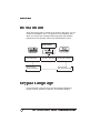
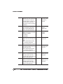
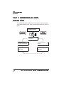
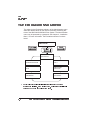
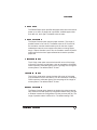
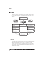
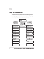
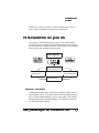
The Configuration Menus
The Configuration menu is divided into three main menus: Installation, Operator Control, and Administration.
■
The Installation menu, which appears only when the security disk
is inserted in the printer’s disk drive, is used to establish passwords for the Operator Control and Administration menus, and to
set the message window language.
■
The Operator Control menu controls the default settings of most
printer features.
■
The Administration menu is the largest of the three menus. It controls the default settings of printer-host communications, emulations, and other document-processing features.
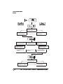
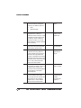
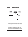
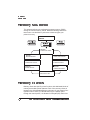
Menus are arranged in a hierarchy as shown on the next page. To
access the configuration menu:
■
Press the Online/Offline key to take the printer off line.
■
Press the Menu key to access the menu.
The top line of the message window displays the current menu level,
and the second line displays the first available option. Move down
one level by pressing the Select key. The Next and Previous keys
change the displayed option in the message window for the current
menu level. The options in each level are arranged in a loop, so
repeatedly pressing either the Next or Previous key returns you to the
option starting point.
Introduction
1-9
The Configuration
Menus
CONFIGURATION
INSTALLATION
CONFIGURATION
ADMINISTRATION
CONFIGURATION
OPERATOR
ADMINISTRATION
DISK OPERATIONS
ADMINISTRATION
COMMUNICATIONS
ADMINISTRATION
MISCELLANEOUS
ADMINISTRATION
ENGINE
ADMINISTRATION
EMULATIONS
ADMINISTRATION
SPECIAL PAGES
ADMINISTRATION
MEMORY
ADMINISTRATION
STARTUP OPTIONS
STARTUP OPTIONS
DO START PAGE
STARTUP OPTIONS
DO ERROR HANDLER
1-10
STARTUP OPTIONS
DO SYS START
QMS 3825/3225/2025 System Administrators Guide
Changing Default
Configuration
Settings
Changing Default
Configuration Settings
There are two types of printer menu options: those that require you to
choose from a selection of possible choices and those that require
you to enter an alphanumeric value. Many default settings may never
need changing.
Selection of Choices
If an option has choices, the second line of the message window displays each choice one at a time. To view all the possible choices for
that option, press the Next key repeatedly. The menu cycles through
all the choices for that option. The Administration/Communications/
Serial/Baud Rate menu is an example of an option with a selection of
choices. The following example shows how to change the baud rate
for serial communication:
1
Press the Online/Offline key to take the printer off line.
2
Press the Menu key. The message window displays
CONFIGURATION
OPERATOR CONTROL
3
Press the Next key until ADMINISTRATION displays on the
second line of the message window:
CONFIGURATION
ADMINISTRATION
4
Press the Select key. This opens the Administration menu.
ADMINISTRATION now displays on the first line of the message window:
ADMINISTRATION
COMMUNICATIONS
Introduction
1-11
Changing Default
Configuration
Settings
5
Press the Select key again. This opens the Communications
menu. COMMUNICATIONS now displays on the first line of the
message window:
COMMUNICATIONS
TIMEOUTS
6
Press the Next key until SERIAL displays on the second line:
COMMUNICATIONS
SERIAL
7
Press the Select key to open the Serial submenu:
SERIAL
MODE
8
Press the Next key until BAUD RATE displays:
SERIAL
BAUD RATE
9
Press the Select key. The first choice in the set of baud rate
values displays on the bottom line. This value is also the current default setting:
BAUD RATE
*9600
10 Press the Next key until the value you want (for example,
2400) displays:
BAUD RATE
2400
11 Press the Select key. The message window displays a confirmation message for three seconds:
2400
IS SELECTED
12 Then, the message window displays the option’s name:
SERIAL
BAUD RATE
You have now changed the baud rate to 2400. The change does not
1-12
QMS 3825/3225/2025 System Administrators Guide
Changing Default
Configuration
Settings
take effect until you save the changes and place the printer back on
line. Review “Saving Printer Configuration Changes” later in this
chapter.
Alphanumeric Values
When an option requires a value, you enter the value one digit or
character at a time. You use the Next and Previous keys to increase
or decrease the displayed character or digit value. Spaces can also
be used when a value, such as a password, must be an exact number
of characters. The Copies option in the Operator Control menu is an
example of an option that requires a value. The following instructions
show how to change a value:
1
Press the Online/Offline key to take the printer off line.
2
Press the Menu key. The following message displays in the
message window:
CONFIGURATION
OPERATOR CONTROL
3
Press the Select key to open the Operator Control menu.
OPERATOR CONTROL now displays on the first line of the
message window:
OPERATOR CONTROL
COPIES
4
Press the Select key again to display the current value:
COPIES
001
5
Notice that the first digit is flashing. (The default copy count
is 1.) You may select any number of copies up to 999. For
this example, we are setting the copy count to 159.
Introduction
1-13
Saving Printer
Configuration
Changes
6
Press the Next key once. The first digit changes from 0 to 1.
Press the Select key.
COPIES
101
7
The second digit is now flashing. Press the Next key until the
second digit changes to 5. Press the Select key.
COPIES
151
8
The third digit is now flashing. Press the Previous key until
the last digit changes to 9.
COPIES
159
9
Press the Select key. The message window momentarily confirms the change you have made:
159 COPIES
IS SELECTED
Then the message window displays the option’s name again.
You have now changed the copy count to 159 copies per print job.
The change does not take effect until you save the change and place
the printer back on line. Review the next section, “Saving Printer Configuration Changes.”
Saving Printer Configuration
Changes
Whenever you change a printer menu option, the printer prompts you
to save the change before you place the printer back on line. Saving a
menu change means that the new value of the option is recorded and
stored in the printer’s memory. Once stored in memory, the value
takes effect automatically whenever the printer is turned on. Follow
these steps to save your configuration changes:
1-14
QMS 3825/3225/2025 System Administrators Guide
Upgrading Print
System Software
1
Press the Online/Offline key. The following message displays in the message window:
SAVE CHANGES?
NO
2
If you want to save all the configuration changes you have
made, press the Next key (the message window displays YES
on the second line), and then press the Select key. Your
changes take effect when you press the Online/Offline key
again.
3
If you do not want to save your changes, just press the
Select key to select NO. Press the Online/Offline key again.
If you ever save a menu change that you did not want to save, you
can always go back into the configuration menu and change it back to
the previous setting. There is also an option for resetting all menu
options to their factory default settings (see “Restore Defaults” in
chapter 8, “Engine, Miscellaneous, and Disk Operations.”).
»
Note: Some Administration menu changes do not take effect until the
printer is restarted. Some changes cause the printer to reboot
automatically. Others cause the message
REBOOT NOW?
*YES
»
Note: to appear in the message window. Press the Select key to reboot
the printer, or the Next and Select keys to choose
NO
and postpone
your configuration changes until the printer is restarted.
Upgrading Print System
Software
Print system software upgrades for the QMS 3825/3225/2025 Print
System are supplied on 3.5" 1.44 MB disks. Installing system software upgrades requires copying the contents of the disks to the
printer’s internal hard disk from the printer’s floppy disk drive or
Introduction
1-15
Upgrading Print
System Software
through the parallel port. (To install through the parallel port you must
have the QMS system software loaded on your host computer). Both
procedures are explained in this section.
Using the Printers Floppy Disk Drive
To install system software upgrades via the printer’s floppy disk drive,
follow these instructions:
1
Turn the printer off and then on again. The following message displays in the message window:
QMS SOFTLOAD x.x
READY TO BOOT
2
Once this message appears, you have 10 seconds to press
the Select key. When you press the Select key, the following
message appears in the message window:
QMS SOFTLOAD x.x
BOOT SYSTEM
»
Note: If more than 10 seconds pass before you press the Select
key, the IDLE message appears. You must return to step 1.
3
Press the Next key until INSTALL TO DISK appears on the
second line of the message window:
QMS SOFTLOAD x.x
INSTALL TO DISK
4
Press the Select key to enter the Install to Disk submenu.
The following message appears in the message window:
INSTALL TO DISK
DISKETTE
5
Press the Select key to load the software from the printer’s
floppy disk drive. The following message appears in the window:
INSTALL TO DISK
TARGET DISK 6
1-16
QMS 3825/3225/2025 System Administrators Guide
Upgrading Print
System Software
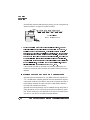
6
Disk 6 is the printer’s internal hard disk. Press the Select
key. The following message displays:
INSTALL TO DISK
INSERT DISK
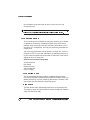
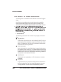
7
Pull the control panel assembly away from the front of the
printer. The floppy disk drive is located inside the printer as
shown below.
8
Insert the first disk into the floppy disk drive, and then press
the Select key.
The message window reads INSTALL TO DISK/INSTALLING; then INSTALL TO DISK/DSK 6: before switching back to
INSTALL TO DISK/INSERT DISK when it is ready for the next
disk. Each disk takes several minutes to load. This process continues until all the disks have been loaded.
9
Press the Select key after inserting each disk.
10 Remove the last disk and close the control panel assembly.
You have now completed installing the new system software and
are ready to boot the system.
Introduction
1-17
Upgrading Print
System Software
11 Press the Menu key. The message window displays the following message:
QMS SOFTLOAD x.x
INSTALL TO DISK
12 Press the Next key until the message window displays the
following message:
QMS SOFTLOAD x.x
BOOT SYSTEM
13 Press the Select key to enter the Boot System submenu. The
following message appears in the message window:
BOOT SYSTEM
HARD DISK
14 Press the Select key and the following message appears:
BOOT SYSTEM
HARD DISK 6
15 Hard disk 6 is the internal hard disk. If you have any external
hard disks connected, you can cycle through them by pressing the Next key. For this example we are using the internal
hard disk. Press the Select key. The system begins loading,
and the following message displays:
BOOT SYSTEM
LOADING x.x
16 At this point, DO NOT TOUCH ANY KEYS until the system
has completed loading. The system may go through many
cycles of rebooting, which may take several minutes. When
the system rebooting is complete, the message window displays:
IDLE
»
Note: If you do touch some keys during this step, you must go
back to step 12 and start from there again.
1-18
QMS 3825/3225/2025 System Administrators Guide
Upgrading Print
System Software
Using the Parallel Port
To install system software upgrades via the parallel port, follow these
instructions:
1
Turn the printer off and then on again. The following message displays in the window:
QMS SOFTLOAD x.x
READY TO BOOT
2
Once this message appears, you have 10 seconds to press
the Select key. When you press the Select key, the following
message appears in the message window:
QMS SOFTLOAD x.x
BOOT SYSTEM
»
Note: If 10 seconds pass before you press the Select key, the IDLE
message appears. You must return to step 1.
3
Press the Next key until INSTALL TO DISK appears on the
second line of the message window:
QMS SOFTLOAD x.x
INSTALL TO DISK
4
Press the Select key to enter the Install to Disk submenu.
Then press the Next key until the following message appears
in the message window:
INSTALL TO DISK
PARALLEL
5
Press the Select key to load the software from the host
system parallel port. The following message appears in the
window:
INSTALL TO DISK
TARGET DISK 6
Introduction
1-19
Upgrading Print
System Software
6
Disk 6 is the printer’s internal hard disk. Press the Select
key. The following message displays:
INSTALL TO DISK
CONNECTING....
7
Go to your host computer and send the system software.
The software is installed when the following message
appears:
INSTALL TO DISK
COMPLETE
8
Once you have completed installing the system software,
you are ready to boot the system. Return to your printer and
press the Menu key. The message window displays the following message:
QMS SOFTLOAD x.x
INSTALL TO DISK
9
Press the Next key until the message window displays the
following message:
QMS SOFTLOAD x.x
BOOT SYSTEM
10 Press the Select key to enter the Boot System submenu. The
following message appears in the message window:
BOOT SYSTEM
HARD DISK
11 Press the Select key and the following message appears:
BOOT SYSTEM
HARD DISK 6
12 Hard disk 6 is the internal hard disk. If you have any external
hard disks connected you can cycle through them by pressing the Next key. For this example we are using the internal
1-20
QMS 3825/3225/2025 System Administrators Guide
Upgrading Print
System Software
hard disk. Press the Select key. The system begins loading,
and the following message displays:
BOOT SYSTEM
LOADING
13 At this point, DO NOT TOUCH ANY KEYS until the system
has completed loading. The system may go through many
cycles of rebooting, which may take several minutes. When
the system rebooting is complete, the following message
appears:
IDLE
»
Note: If you do touch some keys during this stop, you must go
back to step 9 and start from there again.
❖
Introduction
1-21
2
Installation
Menu
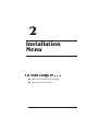
In This Chapter . . .
■
Setting the message window language
■
Setting and using passwords
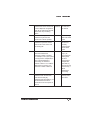
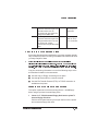
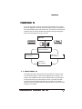
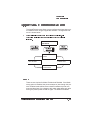
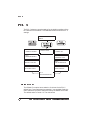
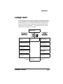
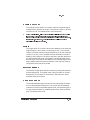
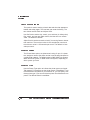
Introduction
Introduction
When the security disk is inserted in the printer’s disk drive, you can
access the Installation menu. The options in the Installation menu
allow you to select the message window language and establish
passwords for the Operator Control and Administration menus
CONFIGURATION
INSTALLATION
INSTALLATION
USE ADMIN PWD
INSTALLATION
KEYPAD LANGUAGE
INSTALLATION
ADMIN PASSWORD
INSTALLATION
OPERATOR PASSWRD
INSTALLATION
USE OPERATOR PWD
Keypad Language
Use the Keypad Language option to select message displays in
English, French, German, or Spanish. The default is English.
2-2
QMS 3825/3225/2025 System Administrators Guide
Passwords
Passwords
Setting Passwords
The two password setting options, Operator Passwrd and Admin
Password, are options that require alphanumeric values, which may
be up to 16 characters in length. If the password you choose is not 16
characters long, you must pad the remainder of the password with
spaces. See chapter 1, “Introduction,” for information on entering
alphanumeric values.
Using Passwords
The password enabling options, Use Operator Pwd and Use Admin
Pwd, can be used to prevent unauthorized access to the printer’s
configuration menu.
If Use Operator Pwd is set On, anyone attempting to enter the Operator Control menu must enter the operator password before accessing
any of the submenus.
If Use Admin Pwd is set On, anyone attempting to enter the Administration menu must enter the Admin Password before accessing any of
the submenus.
Default for both is Off.
❖
Installation Menu
2-3
3
Operator
Control Menu
In This Chapter . . .
■
Copies
■
Duplex and tumble duplex
■
Collation
■
Orientation
■
Input and output bins
■
Chaining input bins
■
Job accounting
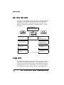
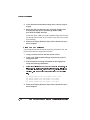
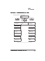
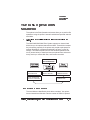
Introduction
Introduction
The options in the Operator Control menu allow you to set the default
values for the various paper handling features of the QMS 3825/
3225/2025 Print System. The Operator Control menu may be protected by a password (see chapter 2, “Installation Menu,” for more
information).
CONFIGURATION
OPERATOR CONTROL
OPERATOR CONTROL
ACCOUNTING
OPERATOR CONTROL
COPIES
OPERATOR CONTROL
DUPLEX
(IF DUPLEXER INSTALLED)
OPERATOR CONTROL
CHAIN INPUTBINS
OPERATOR CONTROL
TUMBLE DUPLEX
(IF DUPLEXER INSTALLED)
OPERATOR CONTROL
OUTPUTBIN
OPERATOR CONTROL
COLLATION
OPERATOR CONTROL
INPUTBIN
OPERATOR CONTROL
ORIENTATION
Copies
The Copies option allows you to set the number of copies of each file
to be printed. The factory default value is 1. The maximum is 999.
Changing this option at the printer control panel effects all print jobs.
Most applications can print multiple copies. If you use your application’s multiple-copy feature, keep the printer’s Copies option set to 1.
3-2
QMS 3825/3225/2025 System Administrators Guide
Duplex
Duplex
The Duplex option allows you to print on both sides of paper, if the
Advanced Paper Handling option (duplexer, large-capacity input tray,
and system table) has been installed. Duplex choices are On and Off.
The default value is Off. Setting Duplex to On at the printer makes all
jobs print duplex. If you want to print individual jobs duplex, leave the
printer setting at Off and choose duplex through your application.
»
Note: If you are printing letterhead in duplex mode, the letterhead
paper must be loaded face down in the input bins.
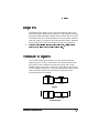
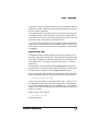
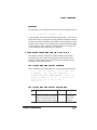
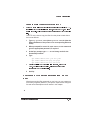
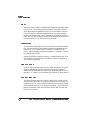
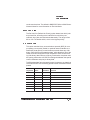
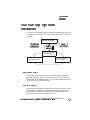
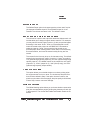
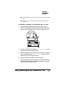
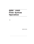
Tumble Duplex
The Tumble Duplex option allows you to specify this advanced
duplexing option. To use Tumble Duplex, the Advanced Paper Handling option must be installed, and both the Duplex and Tumble
Duplex options must be On. Choices for Tumble Duplex are On and
Off with a default value of Off. The following illustration shows the difference between duplex and tumble duplex, using three-holepunched paper as an example.
Side 1
Side 2
Side 1
Portrait
Side 2
Landscape
Duplex
Side 1
Side 2
Portrait
Side 1
Side 2
Landscape
Tumble Duplex
Operator Control Menu
3-3
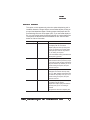
Collation
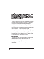
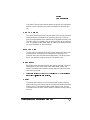
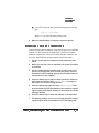
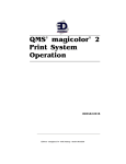
Collation
The Collation option allows you to choose whether to print all copies
of a single page before any copies of the next page or whether to
print one copy of every page before starting the next entire copy.
Choices are On and Off with a default of On. The following illustration
shows the difference between collated and uncollated jobs.
4
4
3
4
2
3
1
3
4
2
3
2
2
1
Collated
1
1
Uncollated
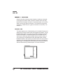
Orientation
Portrait
3-4
Landscape
Orientation allows you to select placement of the image on the physical sheet of paper. The choices are Portrait and Landscape. The
default is Portrait. If you specify orientation through your application,
keep the printer’s Orientation option set to Portrait.The following illustration shows page orientation relative to paper in the input bins.
QMS 3825/3225/2025 System Administrators Guide
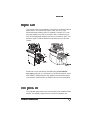
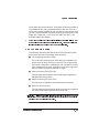
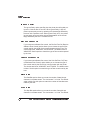
Inputbin
Inputbin
The Inputbin option has a selection of choices for the printer’s default
paper source. The choices are Upper, Lower, and LCIT (if the
Advanced Paper Handling option is installed). Choose LCIT to use
the large-capacity input tray on the 3825, 3225, or 2025 Print Systems or the large-large-capacity input tray on the 3825 or 3225. The
default is Upper. These illustrations show where the input bins are
located:
Upper
Upper
Lower
Lower
LargeCapacity
Large-LargeCapacity
Sheet size may be specified by the QMS DOC %%IncludeFeature:input command or, if the printer is on a DECnet network, by the
VMS SHEET_SIZE parameter. See QMS Crown Document Option
Commands or VMS Interface for QMS Printers for more information.
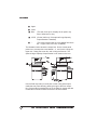
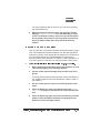
Outputbin
The Outputbin option allows you to choose the printer’s default output
stacker. The default is Upper and the choices for Outputbin are
Operator Control Menu
3-5
Outputbin
■
Upper
■
Lower
■ Side
(The side, face-up bin, displays as an option only
when folded out for use.)
■ LCOS (On the 3825 only, if the optional Large-Capacity
Output Stacker is installed)
■ *
(The printer stacks paper in any available face-down
bin — upper, lower, or LCOS, if installed).
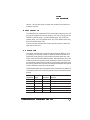
The illustration below shows the output bins. On the control panel
printer icon, the output bins are labeled 1, 2 , and 3 with 1 being the
Upper bin, 2 being the Lower bin, and 3 being the Side bin. The
optional Large Capacity Output Stacker is not shown on the icon.
Upper
Upper
Lower
Side
(folds out)
Lower
Side
(folds out)
LCOS (Optional)
Use the Side output bin for small jobs or when using special print
media that may have difficulty passing through to the main output
bins. Since output is stacked face up in the Side bin, duplex jobs are
not stacked in numerical order and have to be hand sorted.
3-6
QMS 3825/3225/2025 System Administrators Guide
Chain Inputbins
Chain Inputbins
The Chain Inputbins option specifies whether the printer switches to
another input bin containing the same size paper when one input bin
is empty. The default value for Chain Inputbin is On.
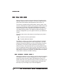
Crown Accounting
Crown accounting, a tool to help you keep track of the use of printer
resources, is available on your QMS Print System, with or without a
network connection.
Paper use is the most commonly monitored resource. However,
Crown accounting also allows you to monitor
»
■
paper use per user
■
time consumed serving each user’s jobs
■
connectivity options
■
frequency of jams
■
times of peak use
■
number, complexity, and average size of jobs per user
■
commonly used features, such as duplexing or finishing
Note: If you are connected to a network via TCP/IP, you have a choice of
using Crown accounting or the standard TCP/IP accounting through
your UNIX host software. See the TCP/IP Protocol Option Users Guide
for more information on TCP/IP accounting.
As jobs are printed on the QMS printer, the system collects information about different job parameters in relation to the jobs. When each
Operator Control Menu
3-7
Crown Accounting
job completes, the printer stores an entry for the job in the Job
Accounting file(s).
Caution:
Do not turn the printer off while the disk is being accessed.
Doing so may cause inconsistencies in the information stored.
Accounting Menu
The Accounting menu includes five submenus, allowing you to enable
or disable job accounting, allocate disk space when accounting is
enabled, reset accounting, store job accounting information in a single job file or in multiple files, and copy the accounting information to
a floppy disk.
Job accounting information may be stored in a single file if it can be
retrieved via FTP on your host. Otherwise, the selected job accounting file should be spread into several files so that each of the files (or
segments) fits on a floppy disk.
Operator Control/Accounting Menu
Accounting Mode
Disk Space
Resetaccounting
Job File Segment
Copy to Floppy
Accounting Mode
The Accounting Mode option enables or disables job accounting.
Choices are Enabled or Disabled with a default of Enabled. When you
disable accounting, any files containing data remain untouched. However, empty files are removed to save disk space.
Disk Space
The Disk Space option allocates disk space for job accounting files.
The range of values is 51200 (50 KB) to 10240 (10 MB) with a default
value of 01024 KB (1 MB).
3-8
QMS 3825/3225/2025 System Administrators Guide
Crown Accounting
The amount of space required for each job can vary between 200 and
250 bytes, so each 1 MB in the job accounting file will store information on 4,000 to 5,000 jobs.
If the selected value is greater than the current value, the file size is
increased to reserve the extra space. If the value is smaller than the
current file size, any empty job accounting files are moved. If only one
file is used and it is not empty, it cannot be shrunk.
If no accounting information exists in the system when shrinking the
usage, the job accounting files are recreated using the new size. The
printer does not ask for confirmation for this operation. It takes effect
immediately.
Resetaccounting
The Resetaccounting option erases the Accounting files and recreates them using the current file size. If this operation is selected when
accounting is disabled, the files are removed but not recreated, thus
saving disk space. The range of values is Yes and No. The default
value is No.
This operation is also available as the resetaccount command for
the admin user at a remote console. See the Remote Console User’s
Guide for more information on the resetaccount command.
When job files are more than 80% full but less than 100% full, the following message displays on the control panel and remote console:
xxxxxxxx FILE xxx% FULL
(xxx% is the percentage full, reported as 85%, 90%, or 95%.) This is
an appropriate time to copy these files to floppies or to transfer them
to your host computer using ftp if it is available to you. Then use the
option to reset the accounting files to empty after they are copied to a
floppy or to a host.
When the file is 100% full, the
xxx FILE IS FULL
message displays.
Operator Control Menu
3-9
Crown Accounting
»
Note: When accounting is enabled and the Job Accounting files are
100% full, no further print jobs are accepted by the printer until
Resetaccounting is selected or until Accounting is disabled. If you
disable Accounting at this time, no job information is stored. You can
retrieve your accounting files while they are full and then do the
Resetaccounting operation. However, to avoid delaying jobs being sent
to the printer, it is advisable to perform the retrieve/reset operations
before the job accounting files fill up.
Job File Segment
The Job File Segment menu allows you to decide whether accounting
information is stored in the printer in a single file or in multiple files.
Choices are Single and Multiple, with Multiple as the default.
Although it is convenient to store accounting data in a single file, the
multiple file option is useful if you must transfer your files to your host
via floppy disk.
If a single file is used, its size equals the Disk Space value described
earlier in this section. The file name will be ACC1.JOB.
If multiple files are selected, their combined size equals the File Size
value described earlier in this section. Each file will be 1 MB, except
the last file, which includes the remaining dedicated space. That is, if
you dedicate 10 MB to accounting and select multiple files, the printer
creates 10 files of 1 MB each. If you dedicate 5.5 MB to accounting,
the printer creates 5 files of 1 MB each and one of 500 KB. The Job
file names will be ACC1.JOB, ACC2.JOB, and so on.
Copy to Floppy
This option copies each of the Accounting files to 1.44 MB, DOS-formatted floppy disks, using the printer’s internal floppy drive.
Insert a disk in the printer’s floppy drive, select the menu entry for the
first file you want to copy, and press Select. It takes several minutes
for the file to copy. When the copying is complete, the message window displays
COPY TO FLOPPY
*EXIT
3-10
QMS 3825/3225/2025 System Administrators Guide
Crown Accounting
Press Select and remove the disk. Then follow the same procedure to
copy additional files, using a separate disk for each file. There is a
menu entry for each possible file, but you need to copy only the ones
you use. The last selection copies the auxiliary accounting files to the
floppy disk. These files — ACC.STA, ACC.PAP, ACC.DIC — are
described later in this chapter.
»
Note: Take the printer off line while retrieving accounting files so that
no jobs will be sent during the retrieval process. Jobs sent while data
is being retrieved may be lost from the accounting files.
Job Accounting Files
The following accounting files are stored in ASCII format on DSK6,
the printer’s hard disk, in the DSK6:/admin directory:
■
Job Accounting File (ACCx.JOB)
This is the main accounting file. When each job completes, the
printer stores an entry for the job in this file. The job accounting
file may be a single file or multiple files, with x as the file number
when multiple files are used. Information in this file is kept intact
after the printer is turned off and back on again.
■
Paper Accounting File (ACC.PAP)
This file contains descriptions of the paper types supported on
the QMS 3825 Print System.
■
Status Accounting File (ACC.STA)
This file stores configuration information about accounting.
■
Dictionary File (ACC.DIC)
This file contains documentation about accounting and a description of the fields used in the other accounting files.
Caution:
All the accounting files are stored in ASCII format to make
it simpler to use the information in different environments after it is
retrieved from the printer's hard disk.
Operator Control Menu
3-11
Crown Accounting
Accounting File Format Description
Accounting files are recorded in ASCII format in a series of tagged
fields.
New fields can be added without losing backward compatibility,
because each field is tagged. A version field is included in the
ACC.STA file to identify the supported fields as the system evolves.
»
Note: Field 45 in the Job Accounting File example on page 3-13
illustrates that new fields can be added to the series but used where
logical, in this case between fields 6 and 7. Field 45, which provides
information about the interface used, was added in response to a
customer request.
Conventions
The following conventions are the same for job, paper, and status
files:
■
Tag Identifiers
These three-digit numbers are used to identify fields. The threedigit number is used instead of a name to minimize use of disk
space. The Dictionary file (ACC.DIC) provides the field names
associated with each tag identifier.
■
String Information
String information for record field values is stored inside braces
(for example, {this is a string}). This allows spaces within strings
and stores only the necessary characters of a string value. String
fields for which no value is specified are stored as {}, instead of
using blanks or the maximum field size.
■
New Records
New records are separated by a <CR> character to increase
readability.
■
Separators
A typical record in any of the accounting files is a sequence of
pairs of tag identifiers and field values separated by commas.
The tag identifier and field value are separated by a colon.
3-12
QMS 3825/3225/2025 System Administrators Guide
Crown Accounting
Example
The following is an example of the format of an accounting file record:
1:
3,
2:{this is a string},
<CR>
In this example, the record has fields identified by tags 1 and 2. Since
these values don't use 3 digits for the tag identifier, spaces are stored
instead, to provide consistency and simplicity while using only a small
amount of extra space. In this example, the value for the field tagged
1 is the integer 3 and the value for the field tagged 2 is a string. The
<CR> represents the carriage return character.
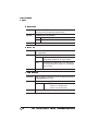
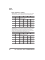
Accounting Files Description of Fields
This section includes examples of a job accounting file, a paper
accounting file, and a status accounting file. Each example is followed by a chart explaining the various fields, using data from the
example to help clarify the fields.
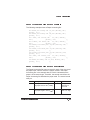
Job Accounting File Record Example
This is a sample record extracted from an actual job accounting file:
0: 6, 1: 1, 2:{ 8h 5m52}, 3:{ 2/ 7/95}, 4:3,
5:{lsmith}, 6:{}, 45:{ IF 1 Ethernet},
7:{Microsoft Word - WW6083WO.DOC}, 8:{}, 9:
2794, 10: 15414, 11: 1, 12:
0, 13: 2, 14: 3,
15: 0, 16:0, 17: 1, 18: 0, 19: 1,
20:3, 21: 2
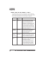
Job Accounting File Record Description
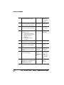
Field Description
ID
0:
Example
0: 6
The Job ID field is the
document’s number. The number
sequence restarts whenever the
printer is turned off and on again.
Operator Control Menu
Explanation
This is the 6th
job since the
printer was
restarted
3-13
Crown Accounting
3-14
1:
This field is the document’s
internally assigned priority.
1:1
Priority 1, the
highest, has
been assigned
to this job
2:
This field indicates the time a
document arrived in the printer
by hour, minute, and second.
2:
Printer received
job at 8:05:52
3:
This field indicates the date a
document arrived in the printer.
3: {2/ 7/95}
Printer received
job on Feb. 7,
1995
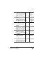
4:
This field is the document’s
completion code:
0 User aborted document
1 Printer aborted document
2 Emulation aborted
document
3 Successfully printed
document
4: 3
Job printed
successfully
5:
The User Name field
5: {lsmith}
corresponds to the %%For DOC.
L Smith sent job
6:
The Host Name field
corresponds to the %%Host
DOC.
6: {}
No host name
assigned
45:
The Connection field indicates
the I/O port in which the job
arrived.
45:IF 1
Ethernet
This job arrived
via Ethernet
7:
The File Name field corresponds 7: {Microsoft
to the %%Title DOC.
Word WW6083WO.
DOC}
8:
The Charge Number field
corresponds to the %%Charge
Number DOC. This field
identifies the account.
{8h5m52}
8: {}
QMS DOC was
used to assign
the title
Microsoft Word WW6083WO.
DOC
No charge
number
assigned
QMS 3825/3225/2025 System Administrators Guide
Crown Accounting
9:
9: 2794
The Compile Time field is the
processor time in milliseconds
(1/1000 second) spent translating
the page description language.
Typically, it also includes
minimal other system activity.
Processor
spent 2.794
seconds
compiling the
page
10
The Print Time field represents 10: 15414
the total elapsed time in
milliseconds(1/1000 second)
used by the document since its
first page started printing until its
last page cleared the printer.
Job took 15.414
seconds from
the start of the
first page to the
end of the last
page
11:
The Header Count field indicates 11: 1
how many images comprise the
document header page(s)
subjob. An image equals one
page face.
There is one
header page
12:
12: 0
The Error Count field indicates
how many images comprise the
document error page(s) subjob.
An image equals one page face.
No error pages
13:
The Body Count field represents 13: 2
the number of images in the
actual document, excluding
multiple copies. An image equals
one page face.
Two pages in
the document
14:
The Simplex Count field is
number of the page faces
printed, including body and
header pages and taking into
consideration multiple copies.
15:
15: 0
The Duplex Count field
represents the sheet count of
duplex pages printed, taking into
consideration multiple copies.
Operator Control Menu
14: 3
Three page
faces printed
No duplex
pages
3-15
Crown Accounting
3-16
16: 0
No finishing
options
16:
The Finishing Options field is a
number formed by adding the
codes for the different options:
0 None
2 Offset Stacking
17:
17: 1
The Chunk Count field
represents the number of
collated chunks for this job. If the
complete document does not fit
in memory, chunk collation is
activated. A value of 1 for this
field indicates no partial collation
was necessary.
18:
The Jam field indicates how
many times the printer jammed
while printing the document.
19:
19: 1
The Paper Types Count field
indicates how many different
types of paper were used in the
document and represents the
number of separate index entries
that follow the main record for the
document in the Job Accounting
file. A <CR> follows this field
before the index entries.
One type of
paper used in
this job
20:
The Index Count field represents 20: 3
the number of sheets of paper of
a specific type used by the
document. The actual description
of the paper is in the Paper
Accounting file.
Job used three
sheets of paper
21:
21: 2
The Index field represents the
record number in the Paper
Accounting file that contains the
description for the preceding
paper count. A <CR> follows
each occurrence of this field.
A description of
the paper type is
in Paper
Accounting file
number 2
18: 0
Entire job
printing in one
collated unit
No jams during
this document
QMS 3825/3225/2025 System Administrators Guide
Crown Accounting
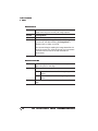
Paper Accounting File Record Example
The following example shows a Paper Accounting file:
22: 8268, 23: 11693, 24: 75, 25:{ white}, 26:{
plain}, 27:{
},
22: 8500, 23: 11000, 24: 75, 25:{ white}, 26:{
plain}, 27:{
},
22: 7165, 23: 10118, 24: 75, 25:{ white},
26:{
plain}, 27:{
},
22: 14000, 23: 8500, 24: 75, 25:{ white},
26:{
plain}, 27:{
},
22: 16535, 23: 11693, 24: 75, 25:{ white}, 26:{
plain}, 27:{
},
22: 14331, 23: 10118, 24: 75, 25:{ white}, 26:{
plain}, 27:{
},
22: 17000, 23: 11000, 24: 75, 25:{ white}, 26:{
plain}, 27:{
},
22: 7500, 23: 10500, 24: 75, 25:{ white},
26:{
plain}, 27:{
},
22: 8268, 23: 5827, 24: 75, 25:{ white}, 26:{
plain}, 27:{
},
Paper Accounting File Record Description
The Paper Accounting file has one record for each of the nine possible paper sizes. Field 21 refers to a specific record in the Paper
Accounting file. In the example above, Field 21 indicates that the
paper is of the second type. Therefore, the second record from the
Paper Accounting file describes the paper used. The second record
tells you:
Field ID Description
Example
Explanation
22:
The Paper Width field contains 22: 8500
the paper width in mils (1/1000").
The paper is
8500 mils or
8.5" wide
23:
The Paper Height field contains 23: 11000
the paper height in mils (1/1000").
Paper is 11000
mils or 11” high
Operator Control Menu
3-17
Crown Accounting
»
24:
The Paper Weight represents the 24: 75
weight per surface square units
(g/m2)
Paper weighs
75 g/m2
25:
The Color field indicates the
color of the paper.
25: white
Paper is white
26:
The Type field indicates
additional properties of the
paper.
26: plain
Paper is plain
27:
The Label field represents a
name for the paper type.
27: { }
No paper type
name
Note: Fields 24, 25, 26, and 27 are designed primarily for future
enhancements to the accounting capabilities.
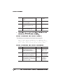
Status Accounting File Record Example
The following is an example of the Status Accounting file:
28: 1, 29: 9, 30: 1048576, 31: 1048576, 32:
74993, 33: 74993, 34: 1, 35: 1, 36: 309, 37:2,
38:1, 39:0, 40:0, 41:31, 42:23, 43:31, 44:31
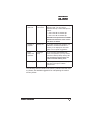
Status Accounting File Record Description
Field ID Description
3-18
Example
Explanation
28:
The Version field indicates the
accounting file’s version
number. The initial version is 1.
28: 1
This is the first
version of the
file
29:
The Number of Paper Types field 29: 9
indicates how many records are
in the Paper Accounting file.
The paper
accounting file
has 9 records
30:
30:
The Job Accounting File Size
field indicates how many bytes 1048576
are dedicated to accounting files.
Maximum is 10 MB.
1048576 bytes,
or 1 MB, is
dedicated to
accounting
QMS 3825/3225/2025 System Administrators Guide
Crown Accounting
31:
31:
The Last Job File Size field
indicates the size of the last file. 1048576
In the multiple-file configuration,
each file is 1 MB except the last,
which holds any remaining
space.
1048576 bytes,
or 1 MB, is in
the last file
32:
The Job File Usage field
indicates in bytes the total
current use in all the job files.
32: 74993
All accounting
files total 74993
bytes
33:
The Current Job File Usage field 33: 74993
indicates in bytes the current
level of use in the current Job
Accounting file.
The accounting
file which is
currently
receiving data
totals 74993
bytes
34:
34: 1
The Maximum Number of Job
Files field indicates the
maximum number of job files.
For example, even if your system
is configured for multiple files, if
only 1 MB is dedicated to
accounting, the maximum
number of files is 1. If 5.5 MB is
dedicated to accounting, the
maximum number of files is 6.
There can be
only 1 job
accounting file.
Although the
printer is
configured for
multiple files
(see field 37)
there is only one
because only 1
MB is
dedicated to
accounting
35:
35: 1
The Current Job File field
indicates which file has been
used most recently. By
comparing this with Field 33, you
can determine which file is
current and how much space is
left in it.
The most
recently used
file is File 1
Operator Control Menu
3-19
Crown Accounting
3-20
36:
The Number of Jobs field
indicates how many documents
are accounted for in the Job
Accounting file(s). A value of 0
can mean that no jobs have
been printed or that accounting
is disabled.
36: 309
Current Job
Accounting files
hold data on
309 jobs
37:
The Multifile field has a value of
1 if a single file is used and a
value of 2 if multiple files are
used to store job information.
37: 2
Job Accounting
is set for
multiple files
38:
The Enabled field indicates
whether accounting is currently
enabled or disabled.
1 Enabled
0 Disabled
38: 1
Accounting is
currently
enabled
39:
The Job File Full flag indicates
whether the Job Accounting file
is full.
1 File is full; Resetaccounting
should be performed
0 Job accounting file is not full
39: 0
Accounting files
are not full
40:
The Paper Accounting File Full 40: 0
flag indicates whether the Paper
Accounting file is full.
1 File is full; Resetaccounting
should be performed
0 Job accounting file is not full
The Paper
Accounting file
is not full
41:
41: 31
The User field indicates the
maximum character length of the
User Name field in the Job
Accounting file. User names are
assigned with QMS DOC.
The User name
can be up to 31
characters
42:
42: 23
The Host field indicates the
maximum character length of the
Host Name field in the Job
Accounting file. Host names are
assigned with QMS DOC.
The Host name
can be up to 23
characters
QMS 3825/3225/2025 System Administrators Guide
Crown Accounting
43:
43: 31
The File field indicates the
maximum character length of the
File Name field in the Job
Accounting file. File names are
assigned with QMS DOC.
The File Name
can be up to 31
characters
44:
44: 31
The Charge field indicates the
maximum character length of the
Charge Number field in the Job
Accounting file. Charge
numbers are assigned with QMS
DOC.
The Charge
field can be up
to 31 characters
Copying the Accounting Files
Accounting files should be transferred to your host computer periodically to keep the printer from being overloaded with data and to allow
you easy analysis of data.
»
Note: The printer must be off line when any of the operations
discussed in this section are performed. Use the
ls command in the
DSK6:/admin directory to see which accounting files you are going to
retrieve. The
ls and cp commands are issued from a remote console.
Copy the accounting information in one of the following ways, which
are described in detail in the next section.
■
Use the Copy to Floppy Accounting menu option
■
Use the cp command from a remote console
■
Use the File Transfer Protocol (FTP) if a TCP/IP connection is
available to the printer
Using the Copy to Floppy Menu Option
This option copies each of the accounting files to 1.44 MB floppy
disks, using the printer’s internal floppy drive.
1
Insert a 3.5", DOS-formatted floppy disk into the printer’s
internal floppy disk drive.
Pull the control panel toward you to open the front of the printer
and access the floppy disk drive.
Operator Control Menu
3-21
Crown Accounting
2
In the Operator Control/Accounting menu, choose Copy to
Floppy.
3
Select the files you want to copy, choosing from the Job
Accounting Files (ACC1.JOB through ACC10.JOB),
ACC.STA, ACC.PAP, ACC.DIC.
Since each file is 1 MB, you need a separate floppy disk for each
file. Not all files will exist, so you need to copy only the ones that
are necessary.
4
Remove the floppy disk from the printer and take it to your
host computer.
Using the cp Command
Use the cp command to download accounting information from the
printer's hard disk to a floppy disk as follows:
1
Using a remote console, take the printer off line.
2
Insert a 3.5" DOS-formatted floppy disk into the printer’s
floppy disk drive.
3
Download the accounting information to the floppy disk
using the following commands:
»
Note: The device names (DSK6 or FLP0) must be uppercase. The
file names can be either uppercase or lowercase. If multiple Job
Accounting files are used, each of the ACCx.JOB files should be
retrieved. (x is the number of each subsequent Job Accounting
file.)
cp
cp
cp
cp
4
3-22
DSK6:/admin/acc1.job FLP0:/acc1.job↵
DSK6:/admin/acc.pap FLP0:/acc.pap↵
DSK6:/admin/acc.sta FLP0:/acc.sta↵
DSK6:/admin/acc.dic FLP0:/acc.dic↵
Remove the floppy disk from the printer and take it to your
host computer.
QMS 3825/3225/2025 System Administrators Guide
Crown Accounting
Using the File Transfer Protocol (FTP)
»
Note: FTP works only when the printer message window displays
IDLE.
If multiple Job Accounting files are used, each of the ACCx.JOB files
should be copied. (x is the number of each subsequent Job Accounting
file.)
Use FTP on the host to copy the files from the printer’s hard disk to
the host as follows:
1
Type ftp printer-name (where printer-name is either the
Ethernet address of the printer or its corresponding Ethernet
name).
2
When prompted for a user id, enter admin as user name and
give the appropriate password, if required.
3
At the ftp> prompt, type bin↵ to use binary mode for the
download procedure.
4
Type
get DSK6:/admin/acc1.job acc.job↵
get DSK6:/admin/acc.pap acc.pap↵
get DSK6:/admin/acc.sta acc.sta↵
»
Note: If multiple Job Accounting files are used, each of the
ACCx.JOB files should be copied. (x is the number of each
subsequent Job Accounting file.)
5
Quit ftp.
Processing Accounting Information on the
Host
After the accounting files are stored on your host, you can create your
own filters (programs) based on your specific requirements using the
file and record descriptions shown earlier in this chapter.
❖
Operator Control Menu
3-23
4
Administration/
Communications
Submenu
In This Chapter . . .
■
Timeouts
■
Serial communications
■
Parallel communications
■
AppleTalk communications
■
Optional interface communications
The
Communications
Submenu
The Communications
Submenu
The default settings for printer-host communications are one portion
of the Administration menu. The Communications submenu is shown
below.
ADMINISTRATION
COMMUNICATIONS
COMMUNICATIONS
TIMEOUTS
COMMUNICATIONS
4-2
OPTIONAL INTERFACES
COMMUNICATIONS
SERIAL
COMMUNICATIONS
APPLETALK
COMMUNICATIONS
PARALLEL
QMS 3825/3225/2025 System Administrators Guide
Timeouts
Timeouts
For many print jobs, the time required for transmission from host to
printer is negligible. However, some print jobs require more transmission and processing time due to their size. The values in the Timeouts
submenu help to ensure reliable transmission while preventing the
printer from being tied up by any one job.
COMMUNICATIONS
TIMEOUTS
TIMEOUTS
PS WAIT TIMEOUT
TIMEOUTS
ESP TIMEOUT
TIMEOUTS
EMUL TIMEOUT
TIMEOUTS
JOB TIMEOUT
PS Wait Timeout
The PostScript Wait Timeout value is the maximum number of seconds the printer waits on data for a PostScript job in process. The
range is 0 to 99999 seconds, and the default value is 30 seconds. If
this time expires and no new data for the job in process has been
received by the PostScript interpreter, the current job is closed. A
value of 0 seconds means that the interpreter does not time out while
waiting on more data.
Administration/Communications Submenu
4-3
Timeouts
Emul Timeout
The Emulation Timeout value is the maximum number of seconds the
printer waits on data for a job (other than PostScript) in process. The
range is 0 to 99999 seconds, and the default value is 5 seconds. If
this time expires and no new data for the job in process has been
received by the printer, the current job is closed. A value of 0 seconds
means that the printer does not time out while waiting on more data.
Job Timeout
The Job Timeout value is the maximum number of seconds that the
printer can process a PostScript job. The range is 0 to 99999 seconds
and the default value is 0 seconds (infinity). A Job Timeout value
greater than 0 seconds prevents jobs that contain an unrecoverable
loop from remaining in the printer and blocking other jobs. However, if
the Job Timeout value is too short, jobs that require extensive processing may not finish before time expires. This timeout can be overridden by your application.
ESP Timeout
The ESP Timeout value is the maximum number of seconds the
printer attempts an emulation selection using the Emulation Sensing
Processor. The range is 0 to 99999 seconds and the default value is 3
seconds. If ESP cannot select an emulation before this time expires,
the printer uses the default emulation to process the job (see chapter
5, “Emulations Submenu”).
Do not set the ESP Timeout to 0 seconds unless you are using the
PostScript interactive mode (see the Mode option in the following
section, “Serial Communication”). A value of 0 disables the timeout.
4-4
QMS 3825/3225/2025 System Administrators Guide
Serial
Communication
Serial Communication
The Serial submenu is shown below.
COMMUNICATIONS
SERIAL
SERIAL
PS PROTOCOL
SERIAL
MODE
SERIAL
EMULATION
SERIAL
HDWE FLOW CTL
SERIAL
MIN K SPOOL
SERIAL
STOP BITS
SERIAL
SPOOL TIMEOUT
SERIAL
DATA BITS
SERIAL
END JOB MODE
SERIAL
XMIT SW FLOW CTL
SERIAL
DEF JOB PRIO
SERIAL
RCV SW FLOW CTL
SERIAL
BAUD RATE
SERIAL
IGNORE PARITY
SERIAL
PARITY
Administration/Communications Submenu
4-5
Serial
Communication
Mode
The Mode option enables or disables the PostScript interactive mode
from the host. The options are Noninteractive, Interactive, and Disabled. Noninteractive establishes one-way communication from the
host to the printer. Interactive establishes two-way communication
between the host and the printer. Disabled turns off serial communication with the host so that the printer stops accepting print jobs over
the serial interface. The default value is Interactive.
Emulation
The Emulation option lets you set the serial interface’s default emulation. You can select from the standard emulations supported by the
printer (PCL 5, Lineprinter, HP-GL, LN03 Plus, imPRESS, ESP,
CCITT, and PostScript), an optional emulation, or Hexdump. The factory default value is ESP.
Selecting Hexdump generates a listing, in hexadecimal format, of all
data received over the interface. Hexdump is useful for diagnosing
communication problems.
Min K Spool
This five-digit value sets the minimum number of kilobytes of system
memory dedicated to the serial interface. The range is 00000 to
99999 and the default value is 00015. See “Dedicating Memory to an
Interface” in chapter 7 for information about the Min K Spool setting.
Spool Timeout
The Spool Timeout option is a numeric value for the number of seconds that the printer waits for additional data from the host while it is
spooling a job. The range is 00000 to 99999 seconds and the default
value is 00030 seconds. If you change this setting, you must ensure
that the new setting does not conflict with the PS Wait Timeout and
Emul Timeout values.
4-6
QMS 3825/3225/2025 System Administrators Guide
Serial
Communication
If the Spool Timeout value expires before the printer has received all
data for a job it is spooling, the printer terminates the spooled print
job.
End Job Mode
This option selects the End of Job terminator to be used for the serial
interface without consideration for interacting timeouts. There are
three choices available: None, QMS EOD (%%EndOfDocument), and
HP EOD (<ESC>%-12345X). Only one form of EOD can be used at a
time. The default is QMS EOD. Refer to QMS Crown Network Notes
for more information on End Job Mode.
Def Job Prio
The Def Job Prio (Default Job Priority) option determines which jobs
are printed first, according to the interface from which they are
received, when jobs are received simultaneously. The range is from
001 to 100 with 001 being the first job. The default is 001.
Baud Rate
Baud Rate is the data transmission rate used by the host. The baud
rate options are 300, 600, 1200, 2400, 4800, 9600, 19200, and
38400. The default value is 9600. Set this option to match the baud
rate used by the host.
»
Note: Baud rates 19200 and 38400 require RTS/CTS protocol (see
Hdwe Flow Ctl, later in this section).
Parity
The Parity option allows you to choose the type of parity checking
performed by the host. Parity acts as a check bit to identify data transmission errors. The options are None, Mark, Space, Odd, or Even.
The default value is None. Set this option to match the parity used by
the host.
Administration/Communications Submenu
4-7
Serial
Communication
Ignore Parity
The Ignore Parity option specifies how the printer should handle parity errors. Choices are On and Off. When Ignore Parity is Off, the
printer reports parity errors by replacing the character(s) affected by
the error with a question mark. When Ignore Parity is On, the printer
ignores parity errors and prints its best interpretation of the character(s) affected by the error. The default is Off.
Rcv Sw Flow Ctl
If your host uses software flow control, the Rcv Sw Flow Ctl (Receive
Software Flow Control) option allows you to choose the type of flow
control used by the printer for its communication with the host. The
choices are None, XON/XOFF, and ETX/ACK. The default value is
XON/XOFF. Set this option to match the type of flow control expected
by the host.
Xmit Sw Flow Ctl
If your host uses software flow control, the Xmit Sw Flow Ctl (Transmit Software Flow Control) option allows you to choose the type of
flow control used by the host for its communication with the printer.
The choices are None, XON/XOFF, and ETX/ACK. The default value
is None. Set this option to match the type of flow control used by the
host.
Data Bits
The Data Bits option allows you to set the number of data bits per
character in the data stream. The choices are 7 or 8 bits. The default
value is 8 bits. Set this option to match the number of data bits transmitted by the host.
Stop Bits
The Stop Bits option allows you to set the number of stop bits per
character in the data stream. The choices are 1 or 2 bits. The default
4-8
QMS 3825/3225/2025 System Administrators Guide
Serial
Communication
value is 1 bit. Set this option to match the number of stop bits transmitted by the host.
Hdwe Flow Ctl
The Hdwe Flow Ctl (Hardware Flow Control) option allows you to pick
the type of hardware flow control used by your host. The choices are
DSR POL (default value: Lo), DSR (default value: Off), DTR POL
(default value: Lo), DTR (default value: On), RTS (default value: Off),
and CTS (default value: Off).
If your host uses hardware flow control, set this option to match the
type used by the host.
PS Protocol
This option sets the binary communications protocol (BCP) for communicating over a serial, parallel, or optional network interface to a
PostScript printer. Binary communications protocol allows any 8-bit
binary value (0-255) to be treated as data, while allowing a few of the
values to function as special control characters. When communicating 8-bit binary data in Binary or Binary Fixed mode, the printer uses
the quoting mechanism of the BCP to distinguish between the special
control characters and print job binary data.
To differentiate data from the special control characters, any data that
is the same as one of the following special control characters must be
quoted:
ASCII
Keyboard
ASCII
Name
ASCII
Hex Value
Control
Function
^A
SOH
0x01
Quote data character
^C
ETX
0x03
Abort job and flush to end of file
^D
EOT
0x04
End-of-file marker
^E
ENQ
0x05
(Reserved for future use)
^Q
DC1
0x11
XON in XON/XOFF flow control
^S
DC3
0x13
XOFF in XON/XOFF flow control
Administration/Communications Submenu
4-9
Serial
Communication
^T
DC4
0x14
Job status request
^\
FS
0x1C
(Reserved for future use)
A data byte is quoted by replacing it with a two-character sequence.
The first character is a ^A (ASCII hex 0x01), and the second character is the character itself XORed with the ASCII value 0x40. For
example, to send the value 0x14 (^T) as data, send the two character
sequence 0x01 0x54 (^A T) instead. (ASCII T in the example is the
result of XORing ^T with 0x40.)
This method of quoting guarantees that whenever any of the eight
control characters is received by the printer, the control function is
intended regardless of whether the preceding character is a ^A. Any
data byte not equal to one of the eight special control characters is
transmitted by sending the data byte.
The settings for this option are as follows:
Normal enables standard, ASCII hex protocol. Data is sent and
received in ASCII format. Print jobs can alter this value through PostScript operators. The default is Normal.
Normal Fixed enables standard, ASCII hex protocol. Print jobs cannot alter this value through PostScript operators.
Binary enables binary communications protocol. Print jobs can alter
this value through PostScript operators.
Binary Fixed enables binary communications protocol. Print jobs
cannot alter this value through PostScript operators.
»
Note: When PS Protocol is set to the Normal Fixed or Binary Fixed
mode, and a print job sends PostScript operators to change the input
device mode, the operators are expected but not acted on.
4-10
QMS 3825/3225/2025 System Administrators Guide
Parallel
Communication
Parallel Communication
The Parallel submenu is shown below.
COMMUNICATIONS
PARALLEL
PARALLEL
PS PROTOCOL
PARALLEL
MODE
PARALLEL
EMULATION
PARALLEL
DEF JOB PRIO
PARALLEL
MIN K SPOOL
PARALLEL
END JOB MODE
PARALLEL
SPOOL TIMEOUT
APPLETALK
DATA BITS
Mode
The Mode option controls whether the parallel interface is active. The
default value is Enabled. If you are not using the parallel interface,
you can select Disabled to prevent any jobs from being received over
the interface.
Emulation
The Emulation option determines the interface’s default emulation.
The default value is ESP. You can select a default emulation for the
interface from the standard emulations supported by the printer (PCL
Administration/Communications Submenu
4-11
Parallel
Communication
5, Lineprinter, HP-GL, LN03 Plus, imPRESS, ESP, CCITT, and PostScript), an optional emulation, or Hexdump.
Selecting Hexdump generates a listing, in hexadecimal format, of all
data received over the interface. Hexdump is useful for diagnosing
communication problems.
Min K Spool
This five-digit value sets the minimum number of kilobytes of system
memory dedicated to the Parallel interface. The range is 00000 to
99999 and the default is 00015. See “Dedicating Memory to an Interface,” in chapter 7, “Memory Submenu,” for information about the Min
K Spool setting.
Spool Timeout
The Spool Timeout option is a numeric value for the number of seconds that the printer waits for additional data from the host while it is
spooling a job. The range is 00000 to 99999 seconds and the default
value is 00030 seconds. If you change this setting, you must ensure
that the new setting does not conflict with the PS Wait Timeout and
Emul Timeout values.
If the Spool Timeout value expires before the printer has received all
data for a job it is spooling, the printer closes the spooled print job.
Data Bits
The Data Bits option sets the number of data bits per character in the
data stream from the host. The choices are 7 and 8 bits. The default
value is 8 bits. Set this value to match your host.
End Job Mode
This option selects the End of Job terminator to be used for the parallel interface. There are three choices: None, QMS EOD (%%EndOfDocument), and HP EOD (<ESC>%-12345X). Only one form of EOD
4-12
QMS 3825/3225/2025 System Administrators Guide
Parallel
Communication
can be used at a time. The default is QMS EOD. Refer to QMS Crown
Network Notes for more information on End Job Mode.
Def Job Prio
The Def Job Prio (Default Job Priority) option determines which jobs
are printed first, according to the interface from which they are
received, when jobs are received simultaneously. The range is from
001 to 100. The default is 001, which is the highest priority.
PS Protocol
This option sets the binary communications protocol (BCP) for communicating over a serial, parallel, or optional network interface to a
PostScript printer. Binary communications protocol allows any 8-bit
binary value (0-255) to be treated as data, while allowing a few of the
values to function as special control characters. When communicating 8-bit binary data in Binary or Binary Fixed mode, the printer uses
the quoting mechanism of the BCP to distinguish between the special
control characters and print job binary data.
To differentiate data from the special control characters, any data that
is the same as one of the following special control characters must be
quoted:
ASCII
Keyboard
ASCII
Name
ASCII
Hex Value
Control
Function
^A
SOH
0x01
Quote data character
^C
ETX
0x03
Abort job and flush to end of file
^D
EOT
0x04
End-of-file marker
^E
ENQ
0x05
(Reserved for future use)
^Q
DC1
0x11
XON in XON/XOFF flow control
^S
DC3
0x13
XOFF in XON/XOFF flow control
^T
DC4
0x14
Job status request
^\
FS
0x1C
(Reserved for future use)
Administration/Communications Submenu
4-13
Parallel
Communication
A data byte is quoted by replacing it with a two-character sequence.
The first character is a ^A (ASCII hex 0x01), and the second character is the character itself XORed with the ASCII value 0x40. For
example, to send the value 0x14 (^T) as data, send the two character
sequence 0x01 0x54 (^A T) instead. (ASCII T in the example is the
result of XORing ^T with 0x40)
This method of quoting guarantees that whenever any of the eight
control characters is received by the printer, the control function is
intended regardless of whether the preceding character is a ^A. Any
data byte not equal to one of the eight special control characters is
transmitted by sending the data byte.
The settings for this option are as follows:
Normal enables standard, ASCII hex protocol. Data is sent and
received in ASCII format. Print jobs can alter this value through PostScript operators. The default is Normal.
Normal Fixed enables standard, ASCII hex protocol. Print jobs cannot alter this value through PostScript operators.
Binary enables binary communications protocol. Print jobs can alter
this value through PostScript operators.
Binary Fixed enables binary communications protocol. Print jobs
cannot alter this value through PostScript operators.
»
Note: When PS Protocol is set to the Normal Fixed or Binary Fixed
mode, and a print job sends PostScript operators to change the input
device mode, the operators are accepted but not acted on.
4-14
QMS 3825/3225/2025 System Administrators Guide
AppleTalk
Communication
AppleTalk Communication
The AppleTalk submenu allows you to configure the printer-host communications when using the AppleTalk interface. The AppleTalk submenu is shown below.
»
Note: AppleTalk does not have an option for Emulation. Only
PostScript emulation jobs can be received over the AppleTalk
interface.
COMMUNICATIONS
APPLETALK
APPLETALK
MODE
APPLETALK
DEF JOB PRIO
APPLETALK
CONNECTION
APPLETALK
MIN K SPOOL
Mode
There are two choices for Mode: Enabled and Disabled. If the Mode
set-up option is Disabled, the printer accepts no jobs through this protocol. Enabled mode allows communication between the host computer and the printer. Any change to this option takes effect only after
turning the printer power off and on again. The default is Enabled.
Administration/Communications Submenu
4-15
Optional Interface
Connection
The Connection set-up option defines the type of connection you are
using. The options are Conventional and Spool, with Conventional
being the default. Spool allows you to use the AppleTalk protocol that
manages interaction between workstations and print servers. This
option allows print spooling. Conventional does not provide print
spooling. Select Conventional to print directly to the printer. Any
change to this option takes effect only after turning the printer power
off and on again.
Min K Spool
This five-digit value sets the minimum number of kilobytes of system
memory dedicated to the AppleTalk interface. The range is 0 to 99999
seconds and the default is 00015. See “Dedicating Memory to an
Interface,” in chapter 7, “Memory Submenu,” for information about the
Min K Spool setting.
Def Job Prio
The Def Job Prio (Default Job Priority) option determines which jobs
are printed first, according to the interface from which they are
received, when jobs are received simultaneously. The range is from
001 to 100. The default is 001, which is the highest priority.
Optional Interface
You can order an optional interface for your QMS printer so you can
connect to other networks. If an optional interface is installed, it
appears in the Communications submenu. Refer to the interface documentation and to your network documentation for information on
connecting your printer to the network and configuring it for network
printing.
❖
4-16
QMS 3825/3225/2025 System Administrators Guide
5
Emulations
Submenu
In This Chapter . . .
■
HP PCL5 emulation settings
■
Lineprinter emulation settings
■
HP-GL emulation settings
■
LN03 Plus emulation settings
■
ESP Default settings
■
PostScript emulation levels
■
CCITT and imPRESS information
■
Optional emulations
The
Emulations
Submenu
The Emulations Submenu
The options in the Emulations submenu of the Administration menu
select the default values for the various document processing features of the QMS 3825/3225/2025 Print System. The Administration
menu may be protected by a password. See chapter 2, “Installation
Menu,” for more information. The Emulations submenu is shown
below.
ADMINISTRATION
EMULATIONS
EMULATIONS
ESP DEFAULT
EMULATIONS
OPTIONAL EMULATION
EMULATIONS
HP-GL
»
EMULATIONS
PCL 5
EMULATIONS
LN03 PLUS
EMULATIONS
EMULATIONS
LINEPRINTER
POSTSCRIPT
Note: This chapter also includes information about two other
standard emulations, CCITT and imPRESS, which are accessible only
through QMS Document Option Commands.
5-2
QMS 3825/3225/2025 System Administrators Guide
ESP Default
Option
ESP Default Option
The ESP Default lets you set which emulation the printer uses if the
Emulation Sensing Processor cannot identify the emulation of a print
job. ESP has a specific length of time within which it attempts to identify the emulation (see “Timeouts” in chapter 4 of this manual). If this
time expires, the printer automatically uses the emulation you select
as ESP Default to process the job.
The choices for ESP Default are those emulations supported by the
printer. The default value is PCL 5. If your print jobs are predominantly one emulation, select that emulation as the ESP Default.
Emulations Submenu
5-3
PCL 5
PCL 5
The PCL 5 submenu contains settings for the default conditions of the
HP LaserJet IIISi emulation. The illustration below shows the PCL 5
settings.
EMULATIONS
PCL 5
PCL 5
DOWNLD LOCATION
PCL 5
DEFAULT FONT
PCL 5
MONOCHROME GL/2
PCL 5
SYMBOL SET
PCL 5
LINES/INCH X100
PCL 5
PCL 5
DEFAULT FONT IDX
LINE TERMINATION
PCL 5
PCL 5
SCALABLE FONTS
POINT SIZEX100
PCL 5
RETAIN TEMPORARY
Default Font
The Default Font option has a selection of choices for the PCL 5
default font. Fonts marked with an asterisk (*) are scalable. Select by
index instructs the printer to select the font by the Default Font Index.
The default value is Courier 12. The choices are
5-4
QMS 3825/3225/2025 System Administrators Guide
PCL 5
Courier12
Courier12 Bold
Courier12 Italic
Courier10
Courier10 Bold
Courier10 Italic
Lineprinter
Times*
Times*Italic
Times*Bold
Times*BldItalic
Univ*
Univ*Italic
Univ*Bold
Univ*bolditalic
Univcond*
Univcond*Italic
Univcond*Bold
Univcond*Bld Itlc
Select by index
Symbol Set
Symbol Set allows you to select the character set used by PCL 5
jobs. The default for Symbol Set is Roman-8. The choices are
Desktop
ECMA-94
HP German
HP Spanish
ISO-2
ISO-4
ISO-6
ISO-10
ISO-11
ISO-14
ISO-15
ISO-16
ISO-17
ISO-21
ISO-25
ISO-57
ISO-60
ISO-61
ISO-69
ISO-84
ISO-85
Legal
Math-8
Microsoft-Pub
PC8-US
PC8-DN
PC-850
Pi-Font
PS-Math
PS-Text
PS-Zapf-Dingbats
Ventura-Dingbats
Ventura-Intl
Ventura-Math
Ventura-US
Windows
Zapf-Dingbats100
Zapf-Dingbats200
Zapf-Dingbats300
Roman-8
Lines/Inch X100
Lines/Inch X100 sets the default line spacing for PCL 5. The number
of lines per inch is set in hundredths. Multiply the desired number of
lines per inch by 100. For example, to set 6.6 lines per inch, enter
660. Choices range from 100 to 4800 (1 to 48 lines) with a default of
600, or 6 lines per inch.
Emulations Submenu
5-5
PCL 5
Line Termination
Line Termination sets the printer response to a carriage return or line
feed character while in PCL 5 emulation. The choices are
CR = CR, LF = LF
CR = CR + LF, LF = LF
CR = CR, LF = CR + LF
CR or LF = CR + LF
CR stands for carriage return. LF stands for line feed. The default is
CR=CR, LF=LF.
Point Size X100
This option sets the point size in hundredths for scalable default fonts
(those listed with an asterisk [*] in the Default Font options). For
example, a 24-point default size is selected by entering 2400. Point
sizes are selectable in increments of 25. The minimum value is 25
(0.25 points), the maximum is 99975 (999.75 points), and the default
is 1200 (12 points).
Retain Temporary
Retain Temporary allows you to choose whether to retain temporary
PCL 5 macros and fonts at the end of each print job. The options are
Off (temporary fonts and macros are deleted at the end of each job),
On (save the temporary macros and fonts), and On Compatibility
(retain the entire state of PCL as well as the temporary macros, fonts,
and patterns from previous PCL jobs). The default is Off.
Scalable Fonts
Scalable fonts allows you to specify whether to scale PCL 5 fonts.
The options are Enable and Disable with the default being Enable.
Disabling Scalable fonts essentially recreates PCL 4 and allows you
to prevent PCL4 documents from inadvertently selecting PCL 5 scalable fonts.
5-6
QMS 3825/3225/2025 System Administrators Guide
PCL 5
Default Font Idx
This option sets the default font index when the default font is set to
select by index. The setting is a numeric value with a minimum of 0, a
maximum of 32767, and a default equal to your Select by Index
value.
Monochrome GL/2
This option allows your printer to emulate a monochrome or color
plotter. Options are On (sets the printer to monochrome, or 2-pen)
and Off (sets the printer to color, or 8-pen). When Monochrome GL/2
is set to On, grayscale patterns are substituted for colors. Default is
On.
Downld Location
This option allows you to set the default storage for PCL objects
(fonts, macros, and patterns). Choices are Memory and Disk. If set to
Memory, all downloaded PCL objects will by default reside in temporary storage in RAM. If set to Disk, they will be stored in the default
disk resource, if present. The default setting is Disk. Systems with a
hard disk and large amounts of memory may enhance system performance by using Memory for PCL object storage. Document Option
Commands specifying locations for downloaded objects will override
this setting on a per job basis.
»
Note: It is possible to set Downld Location to Disk even if no disk is
installed. If Disk is chosen when no disk is present, memory will be used
for storage.
Emulations Submenu
5-7
LN03 Plus
LN03 Plus
The LN03 Plus emulation includes the following menu options:
EMULATIONS
LN03 PLUS
LN03 PLUS
ORIENTATION
LN03 PLUS
PRODUCT ID
LN03 PLUS
AUTOWRAP
LN03 PLUS
RESET OVERRIDE
LN03 PLUS
PAPER SIZE
LN03 PLUS
Y-ORIGIN INSET
LN03 PLUS
PAPER OVERRIDE
LN03 PLUS
X-ORIGIN INSET
Product ID
The Product ID setting is the emulation printer model. If your host
sends a Device Attributes request to the printer, the printer responds
with the product ID. You can select LN03, LQP02, or LA100. The factory default setting is LN03.
Autowrap
The Autowrap setting determines whether text that exceeds the right
margin “wraps” to the next line on the page. The range is On and Off.
The default setting is On (wrap text to next line).
5-8
QMS 3825/3225/2025 System Administrators Guide
LN03 Plus
Paper Size
The Default Paper option specifies the paper size that is to be used at
power up or when no paper size is specified. Available paper sizes
are Letter, A4, and Legal. The default value is Letter.
Paper Override
The Paper Override option sets the paper selection. The range of
possible values is On and Off. The default value is Off. If set to Off,
the emulation uses the transformation point for the size of paper
selected and uses the current paper size (does not change paper
trays). If Paper Override is set to On, the emulation uses the transformation point for the size of paper selected and uses the specified
paper size.
X-Origin Inset
The X-Origin Inset option moves the lower-left corner of the image
(0,0) to the right from 0 to 300 dots (1 inch at a resolution of 300 dpi).
Use this option to eliminate clipping of the right edge of the image on
some systems. The default offset is 75 dots.
Y-Origin Inset
The Y-Origin Inset option moves the lower-left corner of the image
(0,0) downward from 0 to 300 dots (1 inch at a resolution of 300 dpi).
Use this option to eliminate clipping of the top edge of the image on
some systems. The default offset is 75 dots.
Reset Override
The Reset Override option determines whether the printer automatically resets to the initial power-up configuration before every print job
or whether it retains the configuration from the previous print job. The
range of possible values is Off and On. The default setting is Off.
Emulations Submenu
5-9
PostScript
Orientation
The Orientation option specifies the orientation to be used by the
LN03 Plus emulation. The range of possible values is Portrait and
Landscape. The default value is Portrait. Portrait orientation has the y
axis parallel to the long edge of the page. Landscape orientation has
the y axis parallel to the short edge of the page.
»
Note: This option applies only to the LN03 Plus emulation. The LN03
Plus emulation respects orientation only when it is set through the
LN03 Plus emulation menu or through the LN03 emulations
orientation command.
PostScript
By selecting PostScript in the Emulations submenu, you are able to
choose which emulation level of PostScript the printer uses to print
your file. The choices are Level 2 for QMS Level 2 emulation, Level 1
B/W for PostScript Level 1 emulation that uses no color operators,
and Level 1 Color for PostScript Level 1 emulation that uses color
operators. Level 2 works for Level 2 files and most Level 1 files. The
default is Level 2.
5-10
QMS 3825/3225/2025 System Administrators Guide
Lineprinter
Lineprinter
The Lineprinter submenu contains settings for the default conditions
for this emulation. The Lineprinter emulation prints simple byte-oriented lineprinter files. A byte-oriented lineprinter handles jobs consisting of a series of bytes, where lines are delimited by carriage
returns and line feed characters. The illustration below shows the
options within the Lineprinter emulation.
EMULATIONS
LINEPRINTER
LINEPRINTER
MARGINS
LINEPRINTER
FONT
LINEPRINTER
POINT SZ 100THS
LINEPRINTER
LINEPRINTER
LINES PER PAGE
CHARACTER MAP
LINEPRINTER
LINEPRINTER
AUTOWRAP
LINE NUMBERING
LINEPRINTER
LINEPRINTER
ORIENTATION
TAB STOPS
LINEPRINTER
LINEPRINTER
FFISCRFF
LFISCRLF
LINEPRINTER
CRISCRLF
Emulations Submenu
5-11
Lineprinter
Font
This option specifies the font to be used to print the current job. Any
PostScript fonts available on the printer can be used. To see a list of
PostScript fonts available, print an advanced status page. The default
is Courier.
Point Sz 100ths
This option is a five-digit value which specifies, in increments of .01
point, the point size of the font to be used to print the current print job.
The range is from 400 (4 points) to 25600 (256 points). The default is
00880 (8.8 points).
Character Map
This selection specifies the type of character map to be used. The
choices are ASCII and EBCDIC. The default is ASCII.
Line Numbering
Line numbering specifies that a five-digit number is to be prefixed to
the beginning of each line. The choices are On and Off with Off being
the default.
Tab Stops
This option specifies the number of spaces between tab stops. The
minimum number of tab stops is 0 and the maximum is 256. The
default is 8.
LF IS CRLF
Use this option to stipulate whether each line feed in the print job is
translated to a carriage return/line feed combination. The choices are
On and Off with On being the default.
5-12
QMS 3825/3225/2025 System Administrators Guide
Lineprinter
CR IS CRLF
CRISCRLF determines whether each carriage return in the print job is
translated to a carriage return/line feed combination. The choices are
On and Off with Off being the default.
FF IS CRFF
This option stipulates whether each form feed in the print job is translated to a carriage return/form feed combination. The options are On
and Off with On being the default.
Orientation
This option specifies whether text is printed Portrait or Landscape.
The default is Portrait.
Autowrap
This option indicates whether long lines are to be wrapped onto the
next line instead of being truncated. The options are On and Off with
Off being the default.
Lines Per Page
This option specifies the number of lines printed on a page before an
automatic page eject. Interline spacing is set to the selected point
size. Logical pages consisting of more lines than specified are split
into multiple pages. The minimum Lines Per Page setting is 1, and
the maximum is 128. The default is 87.
Margins
This option defines the left, right, top, and bottom margins from 0 to
17 inches in .01" increments. The minimum setting is 0 and the maximum is 1700 (17"). The default is 0.
Emulations Submenu
5-13
HP-GL
HP-GL
The HP-GL options contain settings for the default conditions of the
HP-GL (plotter) emulation. The illustration below shows the HP-GL
options.
EMULATIONS
HP-GL
HP-GL
PEN (1-8)
HP-GL
PLOTTER
HP-GL
SCALING PERCENT
HP-GL
HP-GL
PAPER TYPE
ORIGIN
HP-GL
HP-GL
EXPAND MODE
REVERSE IMAGE
HP-GL
ENHANCED MODE
Plotter
The Plotter option selects which type of HP-GL compatible plotter the
QMS printer emulates for HP-GL jobs. The choices are 7470A,
7475A, 7550A, and ColorPro. (Selecting ColorPro does not result in
color printing. Colors are represented by varying gray shades.) The
default value is 7550A.
5-14
QMS 3825/3225/2025 System Administrators Guide
HP-GL
Scaling Percent
The Scaling Percent option is a numeric value for the percentage of
enlargement or reduction of the plot. The minimum value is 1 and the
maximum is 150. The default value is 100 (same size).
»
Note: To scale plots, select the paper size originally used for the plot
in the Paper Type menu; then enter the reduction or enlargement
needed to fit the plot on the new page in the Scaling Percent submenu.
If necessary, enter new x,y coordinates in the Origin submenu to
reposition the plot on the page.
Origin
The Origin option is a numeric value for the distance to move the plot
origin along the x and y axes in increments of .001". The minimum
value is 0, and the maximum values are 8500 (8.5") for the x axis and
11000 (11") for the y axis. The default values are 0000 (x axis) and
00000 (y axis). Values of 0 for both x axis and y axis align the plot origin with the lower-left corner of the paper. The default values move
the plot origin just inside the boundaries of the printable region of the
page. Setting values less than the defaults or too high may result in
lost portions of the plot when printed.
Reverse Image
The Reverse Image option has two choices for printing white plots on
a black background. The default value is Off (print black on a white
background). If you select On, black lines in the plot print in white,
and white lines print in black.
Enhanced Mode
The Enhanced Mode option has two choices that specify the resolution of a downloaded character set. The choices are Off (standard
resolution for fixed- and variable-spaced fonts, 4x8 character grid) or
On (enhanced resolution for variable spaced fonts, 32x32 character
grid). The default value is Off.
Emulations Submenu
5-15
HP-GL
Expand Mode
The Expand Mode option expands the default scaling points (P1 and
P2), the hard-clip plotting range, and the maximum plotting area to
the imageable area of the QMS printer. The default value is Off (do
not expand).
Paper Type
The Paper Type option allows you to scale an image to the defined
paper size when printing a plot image. The choices are A (8.5" x 11"),
A4 (210 mm x 297 mm), B (11" x 17"), A3 (297 mm x 420 mm), or
Scale to Paper. The default value is Scale to Paper.
Pens 1-8
The Pen options set the width and color of the 8 “pens” the printer
uses when printing HP-GL emulation jobs. The pen width may be set
from 0 (0 mm wide) to 60 (60 mm wide). The pen color choices are
Black (100% black), Violet (59% black), Brown (50% black), Gray25%, Gray-50%, Gray-75%, Red (70% black), Orange (25.8% black),
Yellow (11% black), Green (41% black), Blue (89% black), Cyan (30%
black), and Magenta (59% black). The default settings are
5-16
Pen
Width
Color
1
7 mm
Black
2
3 mm
Black
3
3 mm
Red
4
3 mm
Green
5
3 mm
Blue
6
3 mm
Violet
7
3 mm
Orange
8
3 mm
Brown
QMS 3825/3225/2025 System Administrators Guide
CCITT Groups
3 and 4
CCITT Groups 3 and 4
By adding the QMS DOC %%IncludeFeature:emulation (ccitt) to
the beginning of your file, you can access the printer-resident CCITT
Group 3 and 4 emulation.
CCITT Commands
The CCITT command language consists of ASCII text strings that set
options for the CCITT emulation. The options must be set on a
per-image basis because they are returned to their default values
after each image is decompressed. If the correct decompression
options are not set before the decompression begins, the emulation
absorbs the data until it finds a valid end-of-job marker.
Unlike QMS DOC, CCITT commands do not need to be placed at the
beginning of a document but can be placed where needed.
The remainder of this section provides the function, syntax, and
default settings of all available CCITT commands.
Command Syntax
The following conventions are used in the discussion of all CCITT
commands that follow.
mixed-case bold
CCITT command
mixed-case bold
italic
Command variable; replace the variable with
information specific to your document
%%
Introduce the command; you must type these
characters
( )
Enclose command variables; you must type the
parentheses
Emulations Submenu
5-17
CCITT Groups
3 and 4
BitReverse
Function
Causes the CCITT emulation to reverse the bits within
each byte of the image data automatically.
Syntax
%%BitReverse (true/false)
Default
true
Indicates that the bits are to be reversed.
false
Indicates that the bits are not to be reversed.
false
BlockEnd
Function
Indicates whether a CCITT End of Block is included in
the image data.
Syntax
%%BlockEnd (true/false)
Default
true
Indicates that a BlockEnd is required in the
image data. Otherwise, an error results.
false
Indicates that a BlockEnd is not required in
the image data but, if present, it is accepted
with no error.
false
Compression
Function
Sets the data compression type of the data following the
%%ImageData command.
Syntax
%%Compression (type)
type
Default
5-18
0
1
2
Group 4
Group 3, 1-dimensional
Group 3, 2-dimensional
0 (Group 4)
QMS 3825/3225/2025 System Administrators Guide
CCITT Groups
3 and 4
DPI
Function
Sets the print resolution (dots per inch) to match the
scanned resolution of the original image.
Syntax
%%DPI (horizontal vertical)
horizontal
Identifies the horizontal resolution.
vertical
Identifies the vertical resolution.
Default
Currently selected print system resolution.
Notes
This command can also be used to scale the image. DPI
resolutions above the original scanned resolution will
reduce the image while DPI resolutions below the
original scanned resolution will enlarge the image.
EBAMode
Function
Sets the Encoded Byte Align flag, which indicates that
the image data is broken into individual lines that are
each aligned on a byte boundary.
Syntax
%%EBAMode (true/false)
true
Indicates that the data is encoded byte aligned.
false
Indicates that the data is not encoded byte
aligned.
Default
false
Note
EBAMode must typically be used with Group 3 1-D
images, which may or may not be from fax machines.
Emulations Submenu
5-19
CCITT Groups
3 and 4
ImageData
Function
Instructs the emulation to begin decompression of the
image data using the currently set image options.
Syntax
%%ImageData
Default
None—no options.
Notes
You must specify %%ImageSize before %%ImageData.
If you do not, the data following %%ImageData is
absorbed with no effect on the file.
This command begins reading the image data after the
end of the current line. After the image, the input stream
is flushed until the next set of %% characters is
encountered.
ImagePosition
Function
Sets the image position (in 0.001" increments) from the
upper-left corner of the page.
Syntax
%%ImagePosition (x y)
Default
5-20
x
The horizontal location of the image’s upper-left
corner.
y
The vertical location of the image’s upper-left
corner.
0 0—Places the image in the upper-left corner of the
page.
QMS 3825/3225/2025 System Administrators Guide
CCITT Groups
3 and 4
ImageSize
Function
Sets the image size to be used for decompression of the
image data that follows the %%ImageData command.
Syntax
%%ImageSize (width height)
width
The width of the image in pixels.
height The height of the image in pixels.
Default
None.
Notes
This command must be used in order to decompress an
image.
This command must be sent before the %%ImageData
command. If it is not, the image is ignored.
InvertImage
Function
Indicates whether the black and white pixels in the
image are reversed.
Syntax
%%InvertImage (true/false)
Default
true
Indicates that the black and white pixels in the
image are reversed.
false
Indicates that the black and white pixels in the
image are not reversed.
false
Emulations Submenu
5-21
CCITT Groups
3 and 4
JobEnd
Function
Signals the end of a CCITT print job and resets the
printer to the default mode. Ends the job and returns the
printer to ESP mode.
Syntax
%%JobEnd
Default
None—no options.
Notes
If this command is omitted, the printer remains in CCITT
emulation mode until the emulation wait timeout expires
(Administration/Timeouts/Emul Timeout menu).
LineEnd
Function
Sets Line-End flags, which indicate whether CCITT
end-of-lines are included in the image data.
Syntax
%%LineEnd (true/false)
Default
5-22
true
Indicates that end-of-lines are required in the
image data. Otherwise, an error results.
false
Indicates that end-of-lines are not required in the
image data but, if present, are accepted with no
error.
false
QMS 3825/3225/2025 System Administrators Guide
CCITT Groups
3 and 4
PageEnd
Function
Instructs the emulation to eject the current page
(whether or not any data has been printed to it) and
clear the page memory.
Syntax
%%PageEnd
Default
None—no options.
Notes
You must include this command for a page to be printed.
Image data must be included after this command.
If an image has not been decompressed since the
beginning of the job or since the last %%PageEnd, a
blank page is ejected.
Rotation
Function
Sets the rotation to be used when the image is
decompressed.
Syntax
%%Rotation (degree)
degre 0
e
90
180
270
0° (no) rotation
90° rotation
180° rotation
270° rotation
Default
0
Notes
Rotation occurs about the current image position origin
set by the %%ImagePosition command. If no
%%ImagePosition command has been used, rotation
occurs about the origin (0,0).
Any rotation (except 0) about the default image position
(0,0) causes the image to be rotated off the page.
Therefore, any rotation other than 0° must coincide with
a %%ImagePosition command.
Emulations Submenu
5-23
imPRESS
imPRESS
Using %%IncludeFeature:emulation(impress) QMS DOC, you can
access the imPRESS full-page layout and graphics page description
language. For details about imPRESS, see the QMS imPRESS Programming Language guide, provided on disk with your printer.
Optional Emulations
The QMS printer supports optional emulations, such as QUIC II. If an
optional emulation is installed on the printer, the appropriate emulation options display in the Emulations submenu. Refer to that emulation’s documentation for complete information.
❖
5-24
QMS 3825/3225/2025 System Administrators Guide
6
Special Pages
and Startup
Options
Submenus
In This Chapter . . .
■
Header and trailer pages
■
Input and output bins for header and trailer pages
■
Status page types
■
Start-up options
The Special
Pages
Submenu
The Special Pages Submenu
The options in the Special Pages submenu allow you to configure
your printer to print header and trailer pages, and select the type of
status page you would like to print.
ADMINISTRATION
SPECIAL PAGES
SPECIAL PAGES
CALIBRATION PAGE
SPECIAL PAGES
STATUS PAGE TYPE
SPECIAL PAGES
HEADER PAGE
SPECIAL PAGES
HEADER INPUTBIN
SPECIAL PAGES
TRAILER INPUTBIN
SPECIAL PAGES
TRAILER PAGE
Calibration Page
A calibration page helps you test and maintain optimal print quality.
The calibration image contains a gray-scale chart that lets you check
print density and gamma correction to get the best possible gray scaling from your printer.
In addition, the calibration page can serve as a quick reference to
help you determine whether you need your lower or higher resolution
for a print job. Simply print a calibration page at one resolution, and
then reset the printer to the other and print another page. By compar-
6-2
QMS 3825/3225/2025 System Administrators Guide
The Special
Pages
Submenu
ing the two pages, it’s easy to see the difference in screens, in type
quality, and in precision of curves and diagonal lines.
To print a calibration page, go to the Administration/Special Pages/
Calibration page menu. Choices are Yes and No with a default of Yes.
Select Yes, and a calibration page prints when you exit from the
menu.
Header Page
A header page is a separator page that prints before a print job to
help users sort out their jobs. This option controls whether a header
page prints before each job. This option is either On or Off with the
default of Off. (See QMS Crown Document Option Commands for
information on header page contents.)
Header Inputbin
This option selects the input bin from which the header page is
printed. Upper selects the upper bin, Lower selects the lower bin, and
LCIT selects the optional large-capacity or large-large-capacity input
bin, if one is installed. The default value is Upper.
Trailer Page
This option allows you to configure if and when a trailer page is
printed after each job. Trailer pages can help users sort out jobs. The
choices are On, Off, On Error, and Errors Only. The default value is
Off.
For LN03 Plus print jobs only, setting this option to On Error prints a
trailer page (with error messages generated during processing and
printing of your job) only if an error occurred. Setting it to Errors Only
prints error messages on the trailer page and omits other trailer page
information. (See QMS Crown Document Option Commands for information on the trailer page contents.)
Special Pages and Startup Options Submenus
6-3
The Special
Pages
Submenu
Trailer Inputbin
This option selects the input bin from which the trailer page prints.
Upper selects the upper bin, Lower selects the lower bin, and LCIT
selects the optional large-capacity or large-large-capacity input tray, if
one is installed. The default value is Upper.
Status Page Type
This option allows you to choose between the two different status
pages, Standard and Advanced. The default is Standard.
6-4
■
The Standard page includes printer identification, settings, current memory configuration, timeouts, communication settings and
input buffer sizes, and hard disk status. An angle bracket 0.5" (13
mm) from the lower-left corner of the page is provided to assist
with image alignment.
■
The Advanced form, which is several pages long, includes all the
information from the Standard page plus current menu configuration settings and a list of available fonts.
QMS 3825/3225/2025 System Administrators Guide
The Startup
Options
Submenu
The Startup Options
Submenu
The options in the Startup Options submenu, shown below, allow you
to configure your printer to run certain options every time the printer is
turned on.
ADMINISTRATION
STARTUP OPTIONS
STARTUP OPTIONS
DO START PAGE
STARTUP OPTIONS
DO ERROR HANDLER
STARTUP OPTIONS
DO SYS START
Do Start Page
The Do Start Page option allows you to decide whether the printer
produces a start-up page each time it is turned on. The options are
Yes and No with the default being Yes. This option takes effect when
the printer is turned off and on again.
Do Sys Start
Sys Start is a PostScript file residing on the printer’s hard disk. When
Do Sys Start is enabled, the controller checks the hard disk for a
SYS/START file each time it is turned on and executes the file. The
options are Yes and No. The default is Yes.
Special Pages and Startup Options Submenus
6-5
The Startup
Options
Submenu
Do Error Handler
This option activates a debugging tool that allows you to identify PostScript errors during a print job. In order for a change to this option to
take effect, the printer must be turned off and on. The options are Yes
and No. The default is No.
Refer to the PostScript Language Reference Manual (Adobe Systems Incorporated, Reading, MA: Addison-Wesley, 1990, ISBN 0201-18127-4) for more information on PostScript errors.
❖
6-6
QMS 3825/3225/2025 System Administrators Guide
7
Memory
Submenu
In This Chapter . . .
■
Introduction to memory management
■
Memory definitions
■
Evaluation of your printing environment
■
Memory clients
Introduction
Introduction
Memory allows your printer to store and retrieve information that is
required to perform many of its tasks. The memory requirements of
each printer are dictated by the applications that are to be run.
The memory is divided among blocks called “memory clients,” each
of which is dedicated to a specific printing purpose. QMS Crown printers provide you with the unique ability to distribute your printer’s
memory among the various memory clients where it can best serve
your specific printing needs. This chapter provides information on
memory management so you can get the most from your QMS Print
System.
Generally, there are two main reasons to reconfigure your printer’s
memory:
■
To achieve maximum performance
■
To enable additional features
The ability to configure your printer’s memory does not necessarily
mean that you must change your current configuration. If you are
presently using all the features you need, and the printer is performing efficiently, you should not feel compelled to reconfigure your
printer’s memory. Just remember that if your printing needs change,
you can redistribute memory where you feel it would best meet your
printing requirements. On the QMS 3225/2025 printers, you can also
add memory to a maximum of 32 MB. (The QMS 3825 Print System
comes with the maximum 32 MB of memory.)
QMS Memory Management
Managing the memory on your printer is much the same as managing
your personal income. In money management, you have a certain
amount of income and many ways of spending that income. You
decide where that money goes according to what is important to you.
There is no single correct way to manage money, but there is one
best way for you according to your financial obligations.
7-2
QMS 3825/3225/2025 System Administrators Guide
QMS Memory
Definitions
The same is true for managing the memory on your printer. There is
no single correct way for everyone to allocate printer memory. By
evaluating your specific printing needs, you may find a way to configure your printer memory that is more efficient for you than the factory
default settings. For example, if you use a large number of PostScript
fonts of various point sizes, you may want to increase the amount of
memory allocated to the area specified for PostScript fonts. Or you
may want to increase memory to the area that minimizes slowdowns
when collating large print jobs.
Memory configuration affects these things as well as the number of
jobs that can be accepted by the printer, the number of options available simultaneously, the number of downloadable fonts and emulations that can be stored, and overall printer performance.
QMS Memory Definitions
Before you can configure your printer’s memory efficiently, you must
understand the different types of memory and how they work
together. QMS Crown documentation uses the following memory
terms:
Memory—Memory allows your printer to store and retrieve information. It is the space within your printer where information is stored
while being actively worked on.
Memory Clients—A memory client is a specific printer function that
has a dedicated block of memory. Each memory client controls certain features. When insufficient memory is allocated to a specific client, the features it controls may not be accessible.
Excess Memory —The memory remaining after providing all the
memory clients with their specified amounts of memory is automatically added to the Display List client. When memory is needed for
other clients, it can be removed from Display List and reallocated.
Storage—Storage is a device in or on which information can be kept.
There are three main types of storage — ROM, RAM and hard disks.
Memory Submenu
7-3
QMS Memory
Definitions
ROM stores read-only data, RAM represents temporary storage, and
hard disks hold information on a more permanent basis.
ROM (Read Only Memory)—This type of memory contains data and/
or machine-executable instructions that can be read but not modifi ed.
On the QMS 3825/3225/2025 Print System, the operating system
code, resident fonts, and resident emulations are stored in ROM. This
information is not lost when the printer is turned off.
RAM (Random Access Memory)—RAM is the memory your printer
uses to perform each task. It can be written to and read from. Once a
task is complete, the memory is free again to be used for another file.
This memory is volatile, so if your printer loses power while a file is
being sent, you must resend the file. The number and type of features
you can run on your printer simultaneously depend on the amount of
RAM your printer has and how that RAM is distributed. The 3825
Print System comes with 32 MB of RAM, the maximum possible for
the system. The 3225/2025 Print System comes with 16 MB of RAM
which can be upgraded to 32 MB.
RAM Disk—Also called a virtual disk, the RAM disk is an area of
RAM that is used to simulate an additional hard disk. Data can be
written and read more quickly than on a hard disk, but a RAM disk
loses any information stored on it when the printer’s power is turned
off. The frame buffer and spooling buffer are RAM disk clients.
Hard Disk—The QMS 3825/3225/2025 Print System comes standard
with a 270 MB internal SCSI hard disk and can be upgraded to a 340
MB internal hard disk with up to six external hard disks. These hard
disks serve as secondary storage for data like downloaded fonts and
emulations. Hard disks are also used to increase the amount of collation that can be accepted and provide a secondary storage area for
spooled data.
SCSI (Small Computer System Interface)—Pronounced “scuzzy,” a
SCSI port allows you to connect up to six hard disks, providing storage for fonts, emulations, and other files. The SCSI port is optional on
the 3825 Print System but standard on the 3225/2025 Print System.
Volatile Memory—This type of memory can be lost when the printer
loses power. For example, most RAM is volatile.
7-4
QMS 3825/3225/2025 System Administrators Guide
Evaluation of
Your Printing
Environment
Non-volatile Memory—This type of memory is not lost when the
printer loses power.
NV RAM—This is a protected form of RAM, used to store information
such as your printer’s Configuration menu. Configuration options you
have chosen, such as emulations, memory settings, and input bins,
are saved to this non-volatile RAM. This information is not lost when
you turn off your printer.
Physical Memory—The physical memory on your printer is equal to
the amount of RAM installed.
Virtual Memory—Virtual memory extends the effective size of the
printer’s memory by using a disk file or swap file to simulate additional
memory space. It enables the hard disk to accept data swapped from
RAM, temporarily freeing the RAM for other tasks.
Spool —Spooling is temporary storage to hold print jobs until the
printer is available to process them.
Evaluation of Your Printing
Environment
The first step in allocating your printer’s memory is to define your
printing needs. Each of your printer’s features requires a minimum
amount of memory. If you use a feature, you must allocate enough
memory to the client which controls it. On the other hand, if there are
features you do not use, you can take excess memory from the clients which control the unused features and add it to other clients that
need additional memory.
Memory Submenu
7-5
Evaluation of
Your Printing
Environment
Printer Features and Memory Clients
To get started with your memory configuration, check the following
table to see which features you use and which memory clients control
them. Detailed descriptions of the clients begin on page 7-8.
Feature
7-6
Memory
Client
Notes
Hard disk
Disk Cache
An internal hard disk and optional
external hard disks provide storage
space for downloaded fonts and
emulations. They also improve collation
performance, hold spooled data and
provide virtual memory capabilities. You
can access all this more quickly if you
dedicate sufficient memory to the Disk
Cache client. See the formula for setting
Disk Cache on page 7-14.
Resident
emulations
Emulation
The emulation client may need extra
memory if you print complex nonPostScript jobs in different nonPostScript emulations.
Nonresident
emulations
Temporary
Emulation
If you use a downloaded optional
emulation, such as QUIC II, you may
improve performance by increasing the
memory in Temporary Emulation.
Number of
users
Spool Buffers
Additional memory in this client
increases the number of jobs that can
be accepted for spooling
simultaneously, freeing host systems
more quickly. However, if too much
memory is allocated here, throughput
can be slowed because of the time
involved in processing a large spool.
QMS 3825/3225/2025 System Administrators Guide
Evaluation of
Your Printing
Environment
Downloadable fonts
PostScript
Font Cache
If you use many different fonts in many
different sizes, you may need to
dedicate memory to the PostScript Font
Cache:
— 128 to 256 KB for 300x300 dpi
— 000 to 000 KB for 400x400 dpi
— 256 to 512 KB for 600x600 dpi
Remember that performance for RAM
based fonts decreases if this client is
set above its default.
Number of
graphics
Display List
If your files contain many graphics, you
will want to increase the amount of
memory to the display list client. See
page 7-12 for specific suggestions.
Fonts,
forms, and
operators
PostScript
Heap
If you use many downloaded fonts,
forms, and operators, you may need to
increase PostScript Heap memory. Do
not increase this client unless you
receive a virtual memory error.
Collating
Display list
Increasing the memory in the Display
List client can improve collation
performance.
The following sections introduce the memory submenu and the memory clients, with detailed suggestions for manipulating the various
memory clients.
Memory Submenu
7-7
Memory
Submenu
Memory Submenu
This submenu allows you to allocate the system memory (RAM)
among the various memory clients. Read the following sections to
learn how to use the Memory submenu to best configure your
printer’s memory.
ADMINISTRATION
MEMORY
MEMORY
K MEM FOR SPOOL
MEMORY
MEMORY
K MEM FOR PSHEAP
MB PRINTER MEM
MEMORY
K MEM DISK CACHE
MEMORY
MEMORY
K MEM DISPLAY
MEMORY
K MEM PS FONTS
K MEM EMULATION
MEMORY
K MEM EMUL TMP
Memory Clients
Memory clients are specific printer functions with dedicated blocks of
memory that enable printer features. Each of the memory clients is
located in the Administration/Memory submenu of your printer’s Configuration menu. When you allocate memory to a specific client
through the control panel, it is allocated in kilobytes (KB). Each time
7-8
QMS 3825/3225/2025 System Administrators Guide
Memory Clients
you make changes in the Memory submenu, print out a status page
to confirm the memory reallocation. (Refer to chapter 1, “Introduction,” for information on how to print a status page.)
»
Note: The value for each memory client must be divisible by 4 KB. If you
enter a value that is not evenly divisible by 4 KB, it is converted to the
next lower value that is divisible by 4 KB. For example, if you enter 102
KB, the value is lowered to 100 KB, assuming there is enough memory
available.
Spool Buffers
Also known as Host Input and K Mem for Spool, this client stores
incoming data from all the interfaces until the physical print engine
can print the job. When enough memory is allocated to this client, the
host becomes free more quickly, and the number of jobs that the
printer can accept simultaneously is increased. You should consider
the amount of data being sent simultaneously when allocating memory to the spool buffer. Additional hard disks can supplement this client with additional memory needed for spooling. The system will not
allow you to set this memory client too low. The default is Variable.
»
Note: While increasing the size of this client is beneficial in reducing
network traffic, throughput speed is not necessarily increased.
Dedicating Memory to an Interface — Each host interface connection on the printer has its own submenu. Within each of these submenus is an option for allocation of Min K Spool. Use the Min K Spool
setting under each interface in the Communications submenu to dedicate memory to an interface. The value of an interface’s Min K Spool
is the number of kilobytes dedicated to spooling jobs received over
that interface. The default value for each interface’s dedicated spooling space is 15 KB.
Min K Spool is a numeric value. The maximum amount of memory
that you may dedicate to a single interface is the amount of excess
memory available in the printer. The minimum amount is 0 KB.
»
Note: Setting the value to 0 KB does not disable the interface.
Instead, unallocated memory is divided among any interfaces with a
Min K Spool value of 0 KB.
Memory Submenu
7-9
Memory Clients
Increasing an interface’s Min K Spool value subtracts from memory
available for other purposes. For example, setting the serial interface
Min K Spool to 20 KB takes an additional 5 KB away from the available memory. Increasing an interface’s dedicated spooling memory
does not change the interface’s priority. All jobs received by the
printer are handled on a first-come, first-served basis, regardless of
the interface receiving the jobs.
If you do not use one or more of the printer interface connections, you
may disable that interface. Any disabled interface’s Min K Spool area
(15 KB) is added to the excess memory in the Display List. Each
interface submenu has a mode setting that allows you to disable it.
PS Heap
Also known as K Mem PS Heap, PostScript VM, and Virtual Memory,
this client holds downloaded fonts, PostScript operators, and forms.
Inefficiently coded PostScript jobs can consume an infinite amount of
virtual memory or leave objects in the PS (PostScript) heap after the
print jobs are completed, leading to virtual memory errors. If not
enough memory is allocated to the PS heap, the job cannot print.
Increasing the memory allocated to this client allows more complex
jobs to print and increases the number of fonts that can be downloaded to virtual memory. However, this client should be increased
only if you receive a virtual memory error when attempting to print a
job or download a font and only in small increments until the error
message goes away. Excess memory in the PS heap is not used. The
system will not allow you to set this memory client too low. The maximum setting is 99999. The default is Variable.
PostScript Font Cache
Also known as K Mem PS Fonts and Font Cache, this memory client
stores bitmapped representations of previously scaled PostScript
fonts. This process reduces the number of times a font must be converted from outline form to bitmap form. Printing pages that have
characters already stored in the font cache is much faster than printing characters not yet in the font cache.
7-10
QMS 3825/3225/2025 System Administrators Guide
Memory Clients
As the font cache memory fills, the printer erases bitmapped characters that have been in the cache longer than the others without being
used to make room for new characters. By increasing the memory
allocated to this client, the printer can store more characters and
spend less time erasing and replacing characters in the cache.
Normally, you do not need to change this memory client unless you
use a large number of fonts at various point sizes. If you do, you may
allocate additional memory to this client to improve printer performance. There is no specific formula to use in figuring the amount of
memory required by the font cache, but after a certain point, large
font caches cause the printer to take longer to print than smaller font
caches because of the search time through the cache.
The recommended font cache size is in the following ranges:
■
128 KB to 256 KB for 300 dpi printing
■
200 KB to 400 KB for 400 dpi printing (3225/2025 Print Systems)
■
200 KB to 400 KB for 600 dpi printing (3825 Print System)
You should experiment to see what font cache size works best for
you. The system will not allow you to set this memory client too low.
The maximum setting is 99999 and is related to the total amount of
memory and the amount of memory configured to the other clients.
The default is 256 KB.
Emulation
Also known as K Mem Emulation, this client is used to store any available emulations, such as CCITT, LN03 Plus, HP PCL, HP-GL, and
imPRESS. Increasing this client’s memory allows more complicated
non-PostScript jobs to print and allows larger emulations or multiple
emulations to be loaded and ready to process jobs.
If an emulation is loaded to process a print job and there is not
enough memory in the emulation client, another emulation already
loaded may be unloaded automatically to obtain enough memory. If
you notice a delay in printing between jobs that have different nonresident emulations, it is possible that the emulations are having to
reload each time they are run. Adding to the emulation client may
Memory Submenu
7-11
Memory Clients
eliminate the unloading and reloading of these emulations and, consequently, increase throughput.
Also, increase the emulation client if you are printing complex nonPostScript jobs that may require more memory to process correctly.
The system will not allow you to set this memory client too low. The
maximum value is 99999. The default is Variable.
Temporary Emulation
Also known as K Mem Emul Tmp and Emulation Temporary, this client sets the amount of system memory to be used by non-PostScript
emulations for storing downloaded fonts, forms, and macros. By dedicating a portion of memory to this client, QMS Crown printers can
perform “context switching,” which is the ability to retain downloaded
fonts and forms even after the printer changes from one emulation to
another. Context switching prevents unnecessary repetitive downloading and traffic congestion on networks.
Normally, this memory client does not need to be changed unless you
plan to download many different non-PostScript fonts. The system
will not allow you to set this memory client too low. The maximum setting is 99999 and the default is Variable.
Display List
Also known as K Mem Display, the display list stores compressed
representations, or blocks, of the pages to be printed. It takes approximately 1 compressed block for a 8.5" x 11" text page, 4 compressed
blocks for an 8.5" x 11" page that includes some graphics, and as
many as 500 compressed blocks for an extremely complex 8.5" x 11"
page.
Many pages of compressed blocks belonging to multiple print jobs
can be stored at the same time in the display list. If enough memory is
allocated to this memory client, a page can always be ready to print
as soon as another page has been imaged to the print engine. It
takes approximately 32 KB of memory for each compressed block on
your QMS 3825/3225/2025 Print System.
7-12
QMS 3825/3225/2025 System Administrators Guide
Memory Clients
Increasing the amount of memory in this client may improve printing
throughput and minimize slowdowns due to duplexing, collating, or
printing complex pages. When large jobs are sent to the printer for
multiple collated copies, the printer may collate a chunk — perhaps
50 pages of each copy — before starting another chunk. Increasing
the Display List memory can increase the size of collated chunks so
you have less hand sorting to do.
The Display List is also the excess memory client. Any unallocated
memory is stored in this client. The system will not allow you to set
this memory client too low. The maximum value is 99999 and the
default is Variable.
Disk Cache
Also known as K Mem Disk Cache, the Disk Cache is a high-speed
temporary buffer for data going to and from the hard disk drive. It can
speed the printer in two ways:
■
Information such as fonts or logos that may be referenced
frequently may still be in the cache and may not have to be
pulled off the disk every time it is needed.
■
When writing to disk, information can be held in the cache
temporarily until it is more convenient to write to disk.
For example, if many fonts are stored on disk, they can be accessed
faster by increasing the disk cache size. If no hard disk is used, the
disk cache should be set to zero. However, when hard disks are
installed they are not available until the disk cache client is increased.
The amount of memory needed for the disk cache client depends on
the number of disks and their sizes and on the number of subdirectories on each disk. As long as there is enough memory in the disk
cache, all disks are accessible. If insufficient memory is allocated to
the disk cache, some disks may be seen while others are not.
»
Note: Accessibility of disks is also affected by cabling. See chapter 8,
Engine, Miscellaneous, and Disk Operations Submenus, for details
about cabling requirements.
Memory Submenu
7-13
Memory Clients
The recommended amount of memory for the disk cache client is:
»
■
120 KB minimum, plus
■
.5 KB per MB of disk storage up to 256 MB, plus
■
0.25 KB per MB of disk storage between 256 MB and 512 MB
Note: As the size of the disks double, the needed disk cache per MB of
storage is reduced by half.
For example, the recommended disk cache client size for a 270 MB
hard disk would be 252 KB and for a 340 MB hard disk 269 KB. The
system will not allow you to set this memory client too low. The maximum value is 99999 and the default is Variable.
Frame Buffer
Also known as K Mem Framebuff, this non-configurable client holds
rasterized or bitmapped images of page faces (single sides of
duplexed pages) which are ready to be sent to the physical print
engine.
MB Printer Mem
This non-configurable information field indicates the total virtual memory space available to be split among various memory clients.
System Memory
Also listed as System Use on the status page, this non-configurable
information field is the amount of RAM that is used to run the printer’s
operating system. It is never increased or decreased. The system
memory subtracted from the total amount of RAM identifies the
amount of RAM available for all the other memory clients.
❖
7-14
QMS 3825/3225/2025 System Administrators Guide
8
Engine,
Miscellaneous,
and Disk
Operations
Submenus
In This Chapter . . .
■
Fine tuning image alignment
■
Selecting default paper
■
Naming input and output bins
■
Using the letterhead and rotate duplex options
■
Clearing a maintenance message
■
Other miscellaneous options
■
Hard disk operations
Engine
Submenu
Engine Submenu
The options in the Engine submenu allow you to adjust image alignment, select a default paper size, name the input and output bins, set
resolution and gamma correction, and use two advanced duplexing
options. This submenu also allows you to turn off a MAINTENANCE
DUE message after maintenance has been performed.
ADMINISTRATION
ENGINE
ENGINE
MAINTENANCE DUE
ENGINE
IMAGE ALIGNMENT
ENGINE
DEFAULT PAPER
ENGINE
POWERSAVE MODE
ENGINE
INPUTBIN 1 NAME
ENGINE
PRINT MODE
ENGINE
INPUTBIN 2 NAME
ENGINE
RESOLUTION
ENGINE
INPUTBIN 3 NAME
(OPTIONAL)
8-2
ENGINE
ROTATE DUPLEX
ENGINE
OUTPUTBIN 1 NAME
ENGINE
LETTERHEAD
(OPTIONAL)
ENGINE
OUTPUTBIN 2 NAME
ENGINE
GAMMA CORRECTION
ENGINE
OUTPUTBIN 3 NAME
ENGINE
OFFSET STACKING
ENGINE
TONER LOW ACTION
QMS 3825/3225/2025 System Administrators Guide
Engine
Submenu
Image Alignment
Image Align is a numeric value for adjusting the placement of the
printed image on the page. There are four types of image alignment:
horizontal offset, duplex horizontal offset, vertical offset, and duplex
vertical offset. Values for each setting range from 0 to 300 (1"/25.4
cm) pixels with a default of 100.
Usually, you do not need to use image alignment to adjust image
placement. To check the alignment, print a standard status page on
letter-size paper. An alignment bracket is printed 1/2" (13 mm) from
the lower-left corner of the paper. If the measurements are off, use
the Image Align option to move the image in pixel increments (1/300"
or 0.08 mm).
Horizontal and Vertical Controls
Horizontal and vertical controls are based on the leading edge of the
paper. Although they are consistent, they may appear to be reversed
in function, depending on the leading edge of the paper.
■
Paper fed long edge first, including letter-size, with portraitoriented printing — horizontal and vertical operate as expected.
■
Paper fed long edge first, including letter-size, with
landscape-oriented printing — horizontal and vertical appear
reversed.
■
Paper fed short edge first, such as 11x17, with portrait-oriented
printing — horizontal and vertical operate appear reversed.
■
Paper fed short edge first, such as 11x17, with landscapeoriented printing — horizontal and vertical operate as expected.
Engine, Miscellaneous, and Disk Operations Submenus
8-3
Engine
Submenu
Image Alignment Guidelines
Simplex Pages — Use this table to determine which value to adjust
and whether to increase or decrease it to get the desired results:
To move image
with this
feed edge
up
down
right
left
and this
orientation adjust this control:
short edge portrait
horizontal
below 100
horizontal
above 100
vertical
above 100
vertical
below 100
short edge landscape
vertical
below 100
vertical
above 100
horizontal
below 100
horizontal
above 100
long edge portrait
vertical
above 100
vertical
below 100
horizontal
above 100
horizontal
below 100
long edge landscape
horizontal
below 100
horizontal
above 100
vertical
above 100
vertical
below 100
Duplex Pages — Use this table to determine which duplex value to
adjust and whether to increase or decrease it to get the desired
results. Duplex image alignment settings affect only the front face of
the page. Use simplex settings to adjust the back face.
To move image
with this
feed edge
8-4
up
down
right
left
and this
orientation adjust this duplex control:
short edge portrait
horizontal
above 100
horizontal
below 100
vertical
below 100
vertical
above 100
short edge landscape
vertical
above 100
vertical
below 100
horizontal
above 100
horizontal
below 100
long edge portrait
vertical
below 100
vertical
above 100
horizontal
below 100
horizontal
above 100
long edge landscape
horizontal
above 100
horizontal
below 100
vertical
below 100
vertical
above 100
QMS 3825/3225/2025 System Administrators Guide
Engine
Submenu
Default Paper
The Default Paper option is the paper type the printer uses if a print
job requests the default input bin, but the default input bin is not
inserted. The choices are Letter or A4. The default is Letter.
Input Bin and Output Bin Names
The choices for input bin and output bin names are alphanumeric values that allow you to assign a logical name to each bin. For example,
you may want to load the upper input bin (1) with pre-punched paper
and assign it the name “3hole.” Once you have assigned a name,
users connected to the printer can use QMS DOC commands to
select the input bin “3hole” if they want their job printed on prepunched paper. When entering these names, keep in mind that they
are case sensitive, and must be entered exactly as they are first
named.
The names for the bins may be up to 16 characters long. The default
names for the input bins are “upper” (input bin 1), “lower” (input bin 2),
“lcit” (optional large-capacity input bin), and “llcit” (optional large-large
capacity input bin). The default names for the output bins are “upper”
(output bin 1), “lower” (output bin 2), “side” (face-up tray), and “lcos”
(optional large-capacity output stacker).
Toner Low Action
This option allows you to decide whether to continue printing when
the engine senses it is low on toner. The choices are Stop and Continue, and the default is Stop. If the option is set to Continue, the
printer can print about 100 more pages, but print quality is diminished;
if set to Stop, insert a new toner cartridge.
Offset Stacking
The Offset Stacking option allows you to choose whether consecutive
print jobs are separated by slightly shifting the placement of each job
in the output bin. The choices are Enable and Disable. Enable is the
default.
Engine, Miscellaneous, and Disk Operations Submenus
8-5
Engine
Submenu
Gamma Correction
Gamma correction improves printer output by creating a more gradual change from white to black. However, because some jobs may
benefit from the sharper contrast in uncorrected output, you have the
option of turning off gamma correction. The choices are 0 (gamma
correction is turned off) and 1 (gamma correction is turned on). The
default is 1.
Letterhead
This option appears only if the duplexing unit is installed. Simplex and
duplex jobs normally exit the printer with opposite orientation. The letterhead option allows you to print both simplex and duplex jobs with
the same orientation, so letterhead paper can be loaded from the
same tray for either type job and output does not require sorting. If
you are printing in the letterhead mode, letterhead paper must be
loaded face down in the input bins, as shown below. You may notice a
decrease in the printing speed depending on the mix of simplex and
duplex pages. The options are On and Off with Off being the default.
See the chart following “Rotate Duplex” for further information.
8-6
QMS 3825/3225/2025 System Administrators Guide
Engine
Submenu
Rotate Duplex
This option, which appears only when the optional duplexing unit is
installed, rotates the image 180° to accommodate duplex printing on
pre-punched letterhead paper. Feeding prepunched paper with the
punched edge first can cause paper jams. If you set rotate duplex to
No, you can feed the paper face down with the un-punched edge first.
The options are No and Yes and the default is Yes. See the chart
below for further information.
Rotate Duplex
Letterhead
Effect
Yes
Off
For use with plain paper where simplex
and duplex jobs are not mixed.
Simplex jobs print with top away from
you as you stand at the control panel;
duplex jobs print with the top toward
you, so sorting is required.
This is the default setting and allows the
fastest printing speeds.
Yes
On
For use with letterhead paper.
Load face down with top toward you (as
shown above). Both simplex and duplex
jobs print with the top toward you so no
manual sorting is required, but print
speed is reduced.
No
On
For use with prepunched letterhead.
Load paper face down with top away
from you. Both simplex and duplex jobs
print with the top away from you, so no
manual sorting is required, but print
speed is reduced.
No
Off
For use with plain paper where simplex
and duplex jobs are mixed.
Simplex and duplex jobs print with the
top away from you so no sorting is
required.
Print speed is normal for simplex jobs.
Engine, Miscellaneous, and Disk Operations Submenus
8-7
Engine
Submenu
Resolution
This option sets the default printer resolution for documents. Each
printer has a lower resolution, 300x300 dpi, for everyday memos and
drafts, and a higher setting for camera-ready work. The higher setting
on the 3825 Print System is 600x600 dpi. The higher setting on the
3225/2025 Print System is 400x400 dpi. The higher setting is the
default.
»
Note: To extend the life of the motor, when the 3825 printer is set to
600x600 dpi, the engine automatically throttles back to 300x300
dpi speed after five minutes of inactivity. However, when a print job is
sent, it automatically resets to 600x600 dpi.
Print Mode
The Print Mode allows you to set the print intensity for your jobs,
which can be useful for specialized graphics or CAD jobs. Choices
are Normal, Light, and Dark, with a default of Normal.
Powersave Mode
The Powersave Mode allows you to select a time limit for the printer
to stay at full power when it is not in use. After that time expires, the
printer automatically switches to a low-power state, with the engine
on and the fuser off. When another job is sent, it takes 2.5 minutes for
the printer to warm up. You may turn off the option, so that the printer
remains at full power no matter how long it goes unused, or you may
select a time limit of 15 minutes, 30 minutes, 1 hour, 2 hours, or 3
hours. The default is 1 hour. When the printer is in Powersave Mode
and the time limit has elapsed, the message window displays ENERGY
SAVER instead of IDLE.
Maintenance Due
This option appears in the configuration menu only when there is a
maintenance message in the message window. Use this option to
clear the message after completing the appropriate maintenance.
The options are On and Off. To clear the message, select Off. The
8-8
QMS 3825/3225/2025 System Administrators Guide
Miscellaneous
Options
default is On. Refer to chapter 3, “Periodic Maintenance,” of your
user’s guide for additional information on maintenance.
Miscellaneous Options
The options in the Miscellaneous submenu of the Administration
menu allow you to restore the factory default values to all configuration menu options, to adjust the printer’s internal clock, to change the
printer name, and to change the printer type.
ADMINISTRATION
MISCELLANEOUS
MISCELLANEOUS
RESTORE DEFAULTS
MISCELLANEOUS
CLOCK OPERATIONS
MISCELLANEOUS
PRINTER TYPE
MISCELLANEOUS
PRINTER NAME
Restore Defaults
The Restore Defaults option resets all configuration options to their
factory default values. The factory default values are listed in appendix D, “Factory Default Settings,” of your user’s guide. The Restore
Defaults option takes effect immediately. The choices are Yes and
No, with No being the default.
Engine, Miscellaneous, and Disk Operations Submenus
8-9
Miscellaneous
Options
Clock Operations
This option is used to set the printer’s date and time that appears on
header and trailer pages. This has been pre-set at the factory. The
two choices are Set Clock and Adjust Clock.
Use Set Clock to set the day, month, year, and time (in military time).
Day, month, and year are listed choices, and the time is a numeric
value. The default is variable.
Adjust Clock is used to correct the clock if it is running faster or slower
than real time. The maximum value is 155 seconds per month and
the minimum value is -155 seconds per month. The default is 0 seconds per month.
Printer Name
The Printer Name option, an alphanumeric string of up to 31 characters, assigns a name to the printer so that it can be easily identified on
a multi-printer network. The default value is QMS 3825 Print System,
QMS 3225 Print System, or QMS 2025 Print System, depending on
which system you have.
Printer Type
Use the Printer Type option to indicate the printer type on an AppleTalk network. For example, set the printer type to “LaserWriter” if you
have Macintosh computers on your network. Or, you can specify a different printer type if you want to hide the printer from Macintosh computers. The default value is LaserWriter.
8-10
QMS 3825/3225/2025 System Administrators Guide
The Disk
Operations
Submenu
The Disk Operations
Submenu
The options in the Disk Operations submenu allow you to perform file
operations using the printer’s internal hard disk and optional external
hard disks.
»
Note: Always turn on all external hard disks before turning on the
printer.
The QMS 3825/3225/2025 Print System supports an internal hard
disk and up to six optional external hard disks. These disks increase
the job spooling capacity of the printer and provide ample space for
optional emulations, permanent downloading of fonts, or user file
storage. This section explains how to use the Disk Operations submenu (shown below) to install and remove optional fonts and emulations), back up or restore disk files, and format a new disk.
ADMINISTRATION
DISK OPERATIONS
DISK OPERATIONS
RESTORE DISK
DISK OPERATIONS
INSTALL OPTION
DISK OPERATIONS
BACKUP HARD DISK
DISK OPERATIONS
REMOVE OPTION
DISK OPERATIONS
FORMAT DISK
Identifying Hard Disks
The hard disks are identified by their device numbers. Your printer
has an internal hard disk with a device number of DSK6. If optional
Engine, Miscellaneous, and Disk Operations Submenus
8-11
The Disk
Operations
Submenu
external hard disks are attached to the printer, you can configure their
device numbers in a range from DSK0 to DSK5.
OptionalDisks
Disks
Optional
(DSK0
(DSK0Through
throughDSK6)
DSK5)
DSK6
»
Note: When adding more than three external hard disks, you must
follow all cabling and termination recommendations of ANSI X3T9.2
Small Computer System Interface-2 precisely to ensure optimal
performance. Otherwise, the signal may deteriorate to such a degree
that disks farther down the chain are not accessible. We recommend
that from the first time you add an external hard disk, you follow the
SCSI specification instructions regarding cabling and termination.
Then it should never be necessary to recable earlier connections if you
add additional disks. To obtain a copy of the specification, contact
Global Engineering Documents at 1 (800) 854-7179.
If the internal hard disk is removed or an external hard disk is not
turned on, the printer does not reset non-volatile RAM to the factory
defaults.
Installing Optional Fonts and Emulations
Optional fonts and emulations for your QMS printer are supplied on
3.5" 1.44 MB disks. Installing optional fonts and emulations requires
copying the contents of the disks to the printer’s internal hard disk or
to an optional external hard disk, using the Install Option selection
from the Disk Operations submenu.
Optional fonts and emulations may be installed through the printer’s
floppy disk drive or from a PC through the printer’s parallel or serial
port. Which method you use depends on the font or emulation disks
you have. If your font or emulation disks are labeled
8-12
QMS 3825/3225/2025 System Administrators Guide
The Disk
Operations
Submenu
■
DOS/INTERNAL, use the printer’s floppy disk drive to install
them.
■
xx.ps or xx.eps, use your PC and the printer’s parallel or
serial port.
Procedure for Using the Printers Floppy Drive
1
Press the Online/Offline key to take the printer off line.
2
Pull the control panel assembly away from the front of the
printer. The floppy disk drive is located inside the printer.
3
Use the control panel to display DISK OPERATIONS on the
bottom line of the message window.
4
Press the Select key to enter the Disk Operations submenu.
5
Press the Next key until INSTALL OPTION displays on the
bottom line of the message window.
6
Press the Select key again to install an option.
7
Press the Next key until the address of the target disk (the
destination of the optional emulation) displays on the bottom line of the message window.
Engine, Miscellaneous, and Disk Operations Submenus
8-13
The Disk
Operations
Submenu
8
Press the Select key to select the address.
The display prompts you to insert one of the disks containing the
optional emulation in the printer’s floppy disk drive.
9
Insert the disk.
The message window displays READING DATA until the contents
of the disk have been copied to the hard disk. When the copy process finishes, the message window displays INSTALL COMPLETE.
10 Press the Menu key to return to the Install Option selection.
11 Press the Online/Offline key to prepare the printer for receiving data from the host.
12 Turn the printer off and back on again.
The printer must be rebooted to complete the installation.
Procedure for Using the Printers Parallel or
Serial Port
If necessary, connect the PC to the printer’s parallel or serial port.
1
Turn on the printer, and wait for IDLE to appear in the message window.
2
Insert the emulation disk in your PC’s 3.5" disk drive, and at
the DOS prompt change to that drive (for example, if you’re
using the A drive, type a:↵).
3
Send the emulation to the printer’s hard disk.
»
Note: If more than one hard disk is available, the emulation
automatically installs itself on the disk with the most free
storage space.
■
If your PC and printer are connected through the parallel port,
type
copy /b *.ps lpt#↵
where # is 1 to 3 and /b refers to binary files.
8-14
QMS 3825/3225/2025 System Administrators Guide
The Disk
Operations
Submenu
■
If your PC and printer are connected through the serial port,
type
copy /b *.ps com#↵
where # is 1 to 4 and /b refers to binary files.
4
When the downloading is complete, reboot the printer.
Removing Fonts and Emulations
Use the Remove Option selection if you need to remove an installed
option from the printer’s hard disk. To remove an option, you need the
original 3.5" disk containing the option files. (The Remove Option
selection compares the contents of the disk with the contents of the
hard disk. Matching files are then deleted from the hard disk.)
1
Use the control panel to display the Disk Operations submenu.
2
Before you remove a font or emulation, the printer should be
on and idle.
3
Pull the control panel assembly away from the front of the
printer. The floppy disk drive is inside the printer. (See the
illustration in the “Installing Optional Fonts and Emulations”
section earlier in this chapter.)
4
Press the Select key to enter the Disk Operations submenu;
then press the Next key until REMOVE OPTION displays on
the bottom line of the message window.
5
Press the Select key again to select REMOVE OPTION; then
press the Next key until the address of the hard disk containing the optional emulation displays on the bottom line of the
message window.
6
Press the Select key to select the address of the emulation.
7
The display prompts you to insert a floppy (the disk containing the original optional emulation files) in the floppy disk.
Engine, Miscellaneous, and Disk Operations Submenus
8-15
The Disk
Operations
Submenu
The message window displays READING DATA until the matching files on the hard disk have been deleted.
8
When the removal process finishes, the message window
displays REMOVE COMPLETE. Press the Menu key to return to
the Remove Option selection.
9
Press the Online/Offline key to prepare the printer for receiving data from the host.
Formatting a Disk
Use the Format Disk selection to perform a DOS format of a 3.5" 1.44
MB disk. You may also use this selection to format the printer hard
disk although doing so erases all contents of the disk.
1
Use the control panel to go to the Disk Operations submenu.
Before formatting a disk, the printer should be on and idle.
2
Pull the control panel assembly away from the front of the
printer.
The floppy disk is located inside the printer. (See the illustration in
“Installing Optional Fonts and Emulations,” earlier in this chapter.)
3
Press the Select key; then press the Next key until FORMAT
DISK displays on the bottom line of the message window.
4
Press the Select key again; then press the Next key or Previous key until the address of the disk to be formatted displays
on the bottom line of the message window.
(The floppy is FLP0, the internal hard disk is DSK6, and the external hard disks are DSK0 - DSK5).
5
Press the Select key. The message ARE YOU SURE? displays. If you are sure you want to format the disk, press the
Select key again.
The message window displays FORMATTING.
If you decide that you do not want to format the selected disk,
press the Menu key. This takes you back to step 3, where you
8-16
QMS 3825/3225/2025 System Administrators Guide
The Disk
Operations
Submenu
can select a different disk to format or you can exit by pressing
the Online/Offline key.
6
When the format process finishes, the message window
displays FORMAT COMPLETE. Press the Menu key to return
to the Format Disk selection; then press the Online/Offline
key to prepare the printer for receiving data from the host.
If you formatted a hard disk, the printer automatically
reboots.
Backing Up the Hard Disk
Like any hard disk, your printer hard disks should be backed up regularly. Use the Backup Hard Disk selection from the Disk Operations
submenu to perform a full backup (all files stored on the hard disk) or
an incremental backup (only files dated after the last previous
backup). Refer to the instructions in Chapter 2, “Daily Operations” of
your user’s guide for instructions on using the printer control panel.
»
Note: The printers floppy disk drive requires a 3.5" 1.44 MB disk.
1
Before backing up a hard disk, the printer should be on, and
IDLE should display in the message window.
2
Pull the control panel assembly away from the front of the
printer.
The floppy disk is located inside the printer. (See the illustration in
the “Installing Optional Fonts and Emulations” section, earlier in
this chapter.)
3
Use the control panel to return to the Disk Operations submenu.
4
Press the Select key; then press the Next key until BACKUP
HARD DISK displays on the bottom line of the message window.
5
Press the Select key again; then press the Next key until the
address of the hard disk to be backed up displays on the
bottom line of the message window.
Engine, Miscellaneous, and Disk Operations Submenus
8-17
The Disk
Operations
Submenu
6
Press the Select key; then press the Next or Previous key to
choose between Full or Incremental back up.
7
Press the Select key again. When prompted by the display,
insert a floppy disk in the drive (a blank disk if you are performing a full back up or your most recent back-up disk if
you are performing an incremental back-up).
8
Press the Select key to begin backing up the hard disk.
The message window displays COPYING DATA. If the backup
requires more than one floppy disk, the message window
prompts you to insert another floppy.
»
Note: If the back-up disk has not been formatted when the
backup begins, the printer automatically formats it. If the disk
is not empty, the message
FLOPPY NOT EMPTY
displays in
the message window. If the disk has been write-protected, the
message
WRITE PROTECT
displays in the message window.
Remove the disk, slide the write-protect tab down, return the
disk to the drive, and start over at step 4.
9
When the contents of the hard disk have been backed up, the
message window displays BACKUP COMPLETE. Press the
Menu key to return to the BACKUP HARD DISK selection.
10 Press the Online/Offline key to prepare the printer for receiving data from the host.
Restoring the Hard Disk
Use your back-up disks to restore the contents of the hard disk in the
event of a hard disk failure. Refer to the instructions earlier in this
manual for using the printer control panel.
1
Pull the control panel assembly away from the front of the
printer.
The floppy disk is located inside the printer. (See the illustration in
the “Installing Optional Fonts and Emulations” section, earlier in
this chapter.)
8-18
QMS 3825/3225/2025 System Administrators Guide
The Disk
Operations
Submenu
2
Use the printer control panel to locate the Disk Operations
submenu.
3
Press the Select key to enter the Disk Operations submenu.
Press the Next key until RESTORE HARD DISK displays on
the bottom line of the message window.
4
Press the Select key. When prompted by the display, insert
your back-up disk in the floppy disk drive.
You must insert the back-up disks in sequence. If you insert a
disk out of sequence, the message SEQUENTIAL ERROR displays in the message window. Remove the disk and insert the
correct one to continue.
5
Press the Select key to begin restoring the hard disk.
The message window displays COPYING DATA. When the contents of the floppy disk have been copied to the hard disk, the
message window displays RESTORE COMPLETE.
6
If you have more than one back-up disk, repeat steps 4
through 6 for each disk.
7
Press the Menu key to return to the Restore Hard Disk selection.
8
Press the Online/Offline key to prepare the printer for receiving data from the host.
❖
Engine, Miscellaneous, and Disk Operations Submenus
8-19
A
QMS Customer
Support
In This Appendix. . .
■
Sources of customer support
■
QMS world-wide offices
Sources of Support
Sources of Support
Several sources of help and information are available, depending on
the type of help you need:
Your QMS Vendor
Your local vendor (the one from whom you bought the printer) may be
best equipped to help you. Your vendor has specially trained service
technicians available to answer questions and the equipment to analyze your printer problems.
Your Application Vendor or Manufacturer
Often, “printing” problems have more to do with the application being
used than with the printer. In this case, the application vendor or manufacturer is the best source of help.
Q-FAX
Q-FAX, a QMS information retrieval service, provides application
notes, technical support notes on common printing problems, and
information about printer specifications, options, accessories, consumables, and prices.
In the United States and Canada, call (800) 633-7213 to reach QFAX. In all other countries, call (334) 633-3850. When you call, have
your fax number handy or place the call from your fax machine’s
handset.
You can choose to have either a directory of currently available documents on a particular topic or a specific document sent to you. The
first time you call, request the directory by pressing 2 on your phone
or fax keypad when prompted. Then call back to request specific documents. You can order up to three documents per call.
A-2
QMS 3825/3225/2025 System Administrators Guide
Sources of
Support
QMS Corporate Bulletin Board System
The QMS Corporate Bulletin Board System (BBS) contains technical
support notes, application notes, drivers, patches, and utilities. If you
have technical questions that do not require an immediate reply, you
may leave them on electronic mail for the Sysop (System Operator).
The bulletin board [(334) 633-3632] operates at 1200, 2400, 9600,
and 14400 baud, 8 data bits, no parity, 1 stop bit, with XMODEM,
YMODEM, and ZMODEM capabilities. Contact QMS Customer Technical Support for more information about the bulletin board.
CompuServe
Through CompuServe, you can ask general, non-technical questions,
share information with other users, and access printing information
and programs. When you use CompuServe, go qmsprint takes
you directly to the forum where QMS is located. The QMS library section contains application notes, drivers, utilities, technical information,
and announcement files.
Internet
The QMS server provides access to technical reports, new product
announcements, a trade show schedule, and other general information about QMS.
You can access the QMS server via any one of the many web viewers
available to Internet users. If you don’t have access to a web viewer,
we recommend the NCSA Mosaic web viewer (Mosaic is at
ftp.ncsa.uiuc.edu). The QMS home page is at http://www.qms.com/.
The QMS ftp resource is the ftp.qms.com.
QMS Customer Technical Assurance (CTA)
QMS Customer Technical Assurance is available from 7 am to 6 pm,
Central Standard Time, at (334) 633-4500 (US). You can also fax
questions to CTA at (334) 633-3716 (US). Please indicate whether
you would like a faxed or a phoned reply.
QMS Customer Support
A-3
Sources of Support
If you call for assistance, have the following information ready so our
technicians can help you more quickly:
■
Your phone number, fax number, and shipping address
■
A description of the problem
■
The printer model and serial number
■
The type of host computer you are using
■
The type and version of operating system you are using
■
The interface your are using, and, if serial, the protocol
■
The application and version you are using
■
The emulation you are using
■
Your printer firmware version (listed on status and start-up pages)
QMS National Service Telephone Numbers
»
1 (800) 762-8894
Call for service information and maintenance pricing
for repair of all QMS printers and printers of various
other manufacturers
1 (800) 858-1597
On Site Service and Depot Repair Information
7 am to 7 pm Central Time
1 (334) 633-4300
Extension 2530
Spare Parts Ordering and Information
8 am to 5 pm Central Time
Note: Above numbers are valid in the United States. To contact QMS
in other countries, see world-wide office numbers on the next page.
A-4
QMS 3825/3225/2025 System Administrators Guide
QMS World-wide
Offices
QMS World-wide Offices
United States/
Latin America
QMS, Inc.
One Magnum Pass
Mobile, AL 36618
(334) 633-4300
Product Information: (800) 523-2696
OEM Information: (800) 631-2692
Consumables: (800) 777-7782
Fax: (334) 633-4866
E-mail: [email protected]
Latin America Fax: (334) 639-3347
Asia-Pacific
QMS Asia-Pacific
Melbourne 61 (3) 899 5777
Sydney 61 (2) 901 3235
Tokyo (81) (3) 3437 4030
Canada
QMS Canada, Inc.
9630 Rte. Trans-Canadienne
Saint-Laurent, Québec H4S 1V9
Telephone: (514) 333-5940, (800) 361-3392
Fax: (514) 333-5949
National Service: (800) 268-4969
National Service Fax: (905) 673-7676
Offices in Ottawa, Québec City, Toronto, and Vancouver
Europe,
Middle East,
Africa
Düsseldorf (49) 211/596 1333
London (44) 1 784 442255
Maarssen (31) 3465 51 333
Paris (33) (1) 4107 9393
Stockholm (46) (8) 725 5680
❖
QMS Customer Support
A-5
B
Cable Pinouts
In This Appendix. . .
■
LocalTalk pinouts
■
Serial pinouts
■
IBM PC/XT, PC/AT, and Compatible pinouts
■
Centronics pinouts
LocalTalk
LocalTalk
The table below gives the correct pinouts for the printer end of the 9pin LocalTalk cable used to connect a computer and printer. A 9-to-8pin adapter is included in the kit for the Macintosh end, if needed.
Pin No.
1
2
3
4
5
6
7
8
9
Name
Ground
No Connection
Ground
Transmit+
TransmitNo Connection
Sync
Receive +
Receive -
Serial
The table below gives the correct pinouts for the printer end of the 25pin serial cable used to connect a computer and printer:
Pin No.
Name
9-pin cables 25-pin cables
2
2
Transmit Data
3
3
Receive Data
7
4
Request to Send (optional)
8
5
Clear to Send
6
6
Data Set Ready (optional)
5
7
Signal Ground
8
Data Carrier Detect
4
20
Data Terminal Ready (optional)
1
24
Reserved
9
25
Reserved
B-2
QMS 3825/3225/2025 System Administrators Guide
IBM PC/XT, PC/
AT, and
Compatible
Computers
IBM PC/XT, PC/AT, and
Compatible Computers
The following table shows the suggested pinouts for serial cables for
IBM PC/XT, PC/AT, and compatible computers.
Printer (DB-25S)
1
2
3
4
5
6+8
7
20
IBM PC/XT (DB-25P)
1
3
4
5
4
20
7
6+8
IBM PC/AT
1 (no connection)
2
3
8
7
4
5
1+6
Centronics Parallel
The following table describes the Centronics parallel interface cable
that can be used with your printer. (See “Notes to the Centronics Parallel Cable Pinouts Table” on the next page for more information.)
Signal
Pin No.
1
2
3
4
5
6
7
8
9
10
Cable Pinouts
Return
Pin No.
19
20
21
22
23
24
25
26
27
28
Signal
STROBEDATA 1
DATA 2
DATA 3
DATA 4
DATA 5
DATA 6
DATA 7
DATA 8
ACKNLG-
Direction
In
In
In
In
In
In
In
In
In
Out
B-3
Centronics
Parallel
Signal
Pin No.
11
12
13
16
18
19-30
31
32
33
34
35
Return
Pin No.
29
30
-
Signal
BUSY+
PE+
SELECT
GND
VCC TEST
GND
IPRIME
FAULTGND
RESERVED
RESERVED
Direction
Out
Out
Out
In
OUT
-
Notes to the Centronics Parallel Cable
Pinouts Table
Direction refers to the direction of signal flow as viewed from the
printer.
Return denotes twisted-pair return and is to be connected at signalground level. When wiring the interface, be sure to use a twisted-pair
cable for each signal and never fail to complete connection on the
return side. To prevent noise effectively, these cables should be
shielded and connected to the chassis of the system unit and printer,
respectively.
All interface conditions are based on TTL level. Both the rise and fall
times of each signal must be less than 0.2 microseconds.
Data transfer must be carried out by observing the ACKNLG and
BUSY signal.
The cable must have an overall braided shield, Belden 8345 or equivalent.
Connectors must have shielded housings. The overall shield must be
bonded to the shielded housings at both ends of the cable.
❖
B-4
QMS 3825/3225/2025 System Administrators Guide
Index
A
Accounting
Accounting information on host 3-23
Copying accounting files 3-21
Dictionary file 3-11
Fields, description 3-13
File format description 3-12
File transfer protocol 3-23
Job accounting file 3-11
Paper accounting file 3-11
Status accounting file 3-11
Using the cp command 3-22
Administration menu
Communications submenu 4-2
Disk Operations submenu 8-11
Emulations submenu 5-2
Engine submenu 8-2
Memory submenu 7-8
Miscellaneous submenu 8-9
Special Pages submenu 6-2
Startup Options submenu 6-5
Alphanumeric values 1-13
AppleTalk
Connection 4-16
Def job prio 4-16
Min K Spool 4-16
Mode 4-15
Autowrap 5-13
B
Backup hard disk 8-17
Baud rate 4-7
BitReverse (CCITT command) 5-18
BlockEnd (CCITT command) 5-18
Buffer sizes 1-8
Buffers spooling 7-9
C
Cable pinouts
Centronics parallel B-3
IBM PC/AT B-3
IBM PC/XT B-3
LocalTalk B-2
Serial B-2
Calibration page 6-2
CCITT
Command syntax 5-17
Commands 5-17
CCITT commands 5-17
BitReverse 5-18
BlockEnd 5-18
Compression 5-18
DPI 5-19
EBAMode 5-19
ImageData 5-20
ImagePosition 5-20
ImageSize 5-21
InvertImage 5-21
JobEnd 5-22
LineEnd 5-22
PageEnd 5-23
Rotation 5-23
CCITT Emulation 5-17
Chaining input bins 3-7
Clearing maintenance message 8-8
Clock Operations 8-10
Collation 3-4
Command syntax
CCITT 5-17
Commands
I-2
CCITT 5-17
Communication settings 1-8
Communications
AppleTalk 4-15
Parallel 4-11
Serial 4-5
Communications submenu 4-2
Emulation timeout 4-4
ESP timeout 4-4
Job timeout 4-4
Optional interface 4-16
Parallel communications 4-11
PS wait timeout 4-3
Serial communications 4-5
Timeouts 4-3
Compress (CCITT command) 5-18
CompuServe A-3
Configuration menus 1-9
Administration menu 1-9
Installation menu 2-2
Operator Control 3-2
Connection 4-16
Context switching 7-12
Control Panel
Language 1-8, 2-2
Copies
Number 3-2
Copying accounting files 3-21
cp command 3-22
Customer Support
CompuServe A-3
Internet A-3
Q-FAX A-2
QMS Corporate Bulletin Board A-3
QMS Customer Technical Assurance
A-4
QMS National Service A-4
D
Data bits 4-8, 4-12
Def job prio 4-7, 4-13, 4-16
Default
QMS 3825/3225/2025 System Administrators Guide
Changing settings 1-11
Communication settings 4-2
Paper 8-5
Resolution 8-8
Default font 5-5
Default font Index 5-7
Device numbers
Hard disks 8-11
Dictionary file 3-11
Direction B-4
Disk cache 7-13
Disk file 7-5
Disk Operations submenu 8-11
Backup Hard Disk 8-17
Format Disk 8-16
Installing an emulation 8-12
Installing upgrades 1-15
Removing a printer option 8-15
Restore Disk 8-18
Display list 7-12
Do Error Handler 6-6
Do Sys Start 6-5
DPI (CCITT command) 5-19
Duplex 3-3
Pre-punched paper 8-7
Rotate 8-7
Tumble 3-3
E
EBAMode (CCITT command) 5-19
Emulation temporary 7-12
Emulation timeout 4-4
Emulations 4-11, 7-11
CCITT 5-17
ESP default 5-3
HP-GL 5-14
Installing 8-12
Lineprinter 5-11
LN03 Plus 5-8
Optional emulation 5-24
PCL 5 5-4
PostScript 5-10
Index
Removing 8-15
Submenu 5-2
End job 4-7
End job mode 4-12
End of document 4-7, 4-12
Energy Saver 8-8
Engine submenu 8-2
Default paper 8-5
Gamma Correction 8-6
Gamma correction 8-6
Inputbin name 8-5
Letterhead 8-6
Maintenance Due 8-8
Offset Stacking 8-5
Output bin 8-5
Resolution 8-8
Toner Low Action 8-5
Enhanced mode 5-15
Erasing contents of disk 8-16
ESP default option 5-3
ESP timeout 4-4
Expand mode 5-16
F
Factory 1-8
Fields
Accounting 3-13
Firmware 1-8
Flow control
Hardware 4-9
Software 4-8
Transmit software 4-8
Font Cache
PostScript 7-10
Fonts 1-8
Installing 8-12
Removing 8-15
Format disk 8-16
Frame buffer 7-14
I-3
H
Hard disks 7-4, 8-11
Backup 8-17
Device numbers 8-11
Formatting 8-16
Identifying 8-11
Installation 1-8
Restoring 8-18
Hardware flow control 4-9
Header inputbin 6-3
Header page 6-3
Hexdump 4-6, 4-12
Host input 7-9
HP-GL
Enhanced mode 5-15
Expand mode 5-16
Origin 5-15
Paper type 5-16
Pen width and colors 5-16
Plotter 5-14
Reverse image 5-15
Scaling percent 5-15
I
IBM PC
AT cable pinouts B-3
XT cable pinouts B-3
Identification
Printer 1-8
Identifying hard disks 8-11
Ignore parity 4-8
ImageData (CCITT command) 5-20
ImagePosition (CCITT command) 5-20
ImageSize (CCITT command) 5-21
imPRESS 5-24
Input bins 3-5
Chaining 3-7
Input buffer sizes 1-8
Installation disk 1-8, 2-2
Installation menu 2-2
Installing
I-4
Emulations 8-12
Fonts 8-12
System software 1-15
Upgrades 1-15
Interfaces
AppleTalk 4-15
Network 4-16
Optional 4-16
Parallel 4-11
Serial 4-5
Internet A-3
InvertImage (CCITT command) 5-21
J
Job accounting file 3-11
Job timeout 4-4
JobEnd (CCITT commands) 5-22
K
K Mem Display 7-12
K Mem Emul Temp 7-12
K Mem Emulation 7-11
K Mem Framebuff 7-14
K Mem PS Fonts 7-10
K Mem PS Heap 7-10
Keypad
Language 1-8, 2-2
Keys
Next 1-9
Previous 1-9
Select 1-9
L
Language
Keypad 1-8, 2-2
Message window 2-2
Letterhead printing 8-6
Line termination 5-6
LineEnd (CCITT commands) 5-22
Lineprinter emulation 5-11
QMS 3825/3225/2025 System Administrators Guide
Autowrap 5-13
Character map 5-12
CRISCRLF 5-13
FFISCRFF 5-13
Font 5-12
LFISCRLF 5-12
Line numbering 5-12
Lines per page 5-13
Margins 5-13
Orientation 5-13
Point sz 100ths 5-12
Tab stops 5-12
Lines per page 5-13
LN03 Plus 5-8
Autowrap 5-8
Orientation 5-10
Paper Override 5-9
Paper size 5-9
Product ID 5-8
Reset Override 5-9
X-Origin Inset 5-9
Y-Origin Inset 5-9
LocalTalk interface
Cable pinouts B-2
Non-volatile 7-5
Physical 7-5
PS Font Cache 7-10
PS Heap 7-10
Settings 1-8
Storage 7-3
System memory 7-14
Virtual 7-5, 7-10
Volatile 7-4
Memory submenu 7-8
Menus
Configuration 1-9
Installation 2-2
Main 1-9
Operator control 3-2
Message Window
Language 2-2
Min K Spool 4-6, 4-12, 4-16
Miscellaneous submenu 8-9
Clock Operations 8-10
Restore defaults 8-9
Mode 4-6, 4-11, 4-15
M
Naming input bins 8-5
Naming output bins 8-5
Next key 1-9
Non-volatile memory 7-5
Maintenance Due message 8-8
Margins
Lineprinter 5-13
MB Printer Mem 7-14
Memory 7-3
Allocation 1-8, 7-8
Clients 7-2, 7-3, 7-8
Dedicate to an interface 7-9
Definitions 7-3
Disk Cache 7-13
Display list 7-12
Emulation 7-11
Emulation temporary 7-12
K Mem Framebuff 7-14
Management 7-2
MB Printer Mem 7-14
Index
N
O
Operator Control menu 3-2
Chaining input bins 3-7
Collation 3-4
Copies 3-2
Duplex 3-3
Input bin 3-5
Orientation 3-4
Outputbin 3-6
Tumble duplex 3-3
Optional interface communications 416
I-5
Options
Alphanumeric values 1-13
Installing 8-12
Removing 8-15
Saving changes 1-14
Selection of choices 1-11
Orientation 3-4, 5-13
Origin option 5-15
Output bins 3-6
P
Page orientation 3-4
PageEnd (CCITT command) 5-23
PAP spooling 4-15
Paper accounting file 3-11
Paper tray 3-5
Paper type 5-16
Parallel communications
Data bits 4-12
Def job prio 4-13
Emulation 4-11
End job mode 4-12
Hexdump 4-12
Min K Spool 4-12
Mode 4-11
PS protocol 4-13
Spool timeout 4-12
Parallel interface
Cable pinouts B-3
Parity 4-7
Passwords
Setting 2-3
Using 2-3
PCL 5
Default font 5-5
Default font Index 5-7
Line termination 5-6
Lines per inch 5-5
Point size 5-6
Retain temporary 5-6
Scalable fonts 5-6
Symbol set 5-5
I-6
Pen width/colors 5-16
Physical memory 7-5
Pinouts
Centronics parallel B-3
IBM PC B-3
LocalTalk B-2
Serial B-2
pleTalk 4-15
Plotter 5-14
Point size 5-6
PostScript emulation 5-10
PostScript font cache 7-10
PostScript heap 7-10
PostScript level 5-10
PostScript VM 7-10
PostScript wait timeout 4-3
Powersave mode 8-8
Printer identification 1-8
Printer registration 1-5
Printer setup 1-5
PS Font Cache
Ranges 7-11
PS protocol 4-9, 4-13
PS wait timeout 4-3
Q
Q-FAX A-2
QMS Corporate Bulletin Board System
A-3
QMS Customer Technical Assurance
A-4
QMS DOC 1-6
QMS National Service A-4
QMS World-Wide Offices A-5
R
RAM 7-4
RAM disk 7-4
Record description 3-13, 3-18
Registration 1-5
Removing
QMS 3825/3225/2025 System Administrators Guide
Emulations 8-15
Fonts 8-15
Printer options 8-15
Resolution 7-11, 8-8
Restore
Defaults 8-9
Hard disk 8-18
Retain temporary 5-6
Return B-4
Reverse image 5-15
ROM 7-4
Rotate Duplex 8-7
Rotation (CCITT command) 5-23
S
Saving changes 1-14
Scalable fonts 5-6
Scaling percent 5-15
SCSI 7-4
Select key 1-9
Separate print jobs 8-5
Serial communications 4-5
Baud rate 4-7
Data bits 4-8
Def job prio 4-7
Emulation 4-6
End job 4-7
Hardware flow control 4-9
Ignore parity 4-8
Min K Spool 4-6
Mode 4-6
Parity 4-7
PS protocol 4-9
Software flow control 4-8
Spool timeout 4-6
Stop bits 4-8
Serial interface
Cable pinouts B-2
Service, QMS A-4
Setting
Date 8-10
Default resolution 8-8
Index
Time 8-10
Setup 1-5
Shipment contents 1-4
Software 1-8
Software flow control 4-8
Special pages
Calibration page 6-2
Header inputbin 6-3
Header page 6-3
Status page type 6-4
Trailer inputbin 6-4
Trailer page 6-3
Special Pages submenu 6-2
Spool 7-5
Spool buffers 7-9
Spool timeout 4-6, 4-12
Spooling memory 1-8
Start page 6-5
Startup Options 6-5
Do Error Handler 6-6
Do Start Page 6-5
Do Sys Start 6-5
Status accounting file 3-11
Record description 3-18
Status page 1-8
Printing 1-8
Set type 1-9
Types 1-8
Status page type 6-4
Stop bits 4-8
Swap file 7-5
Symbol set 5-5
System failure
Reload system software 1-15
System memory 7-14
System software
Installing 1-15
System use 7-14
T
Temporary emulation 7-12
Timeout settings 1-8
I-7
Timeouts
Communications 4-3
Emulation 4-4
ESP 4-4
Job 4-4
PS wait 4-3
Trailer inputbin 6-4
Trailer page 6-3
Tray chaining 3-7
Troubleshooting
QMS Customer Technical Assurance
A-4
Tumble duplex 3-3
Typefaces 1-8
Typographic conventions 1-3
U
Upgrades, system software
Installing 1-15
Using file transfer protocol 3-23
V
Vertical offset 8-3
Virtual disk 7-4
Virtual memory 7-5, 7-10
Volatile memory 7-4
❖
I-8
QMS 3825/3225/2025 System Administrators Guide