1
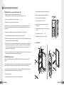
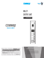
MULTI
ENTRY UNIT
Model No. DRC-nSB / nSC
• Thank you for purchasing our COMMAX product.
• Please carefully read this User’s Guide (in particular, precautions for safety)
before using the product and follow the instructions to use your productexactly.
• The company is not responsible for any safety accidents caused in abnormal
operation of the product.
a513-11, Sangdaewon-dong, Jungwon-gu, Seongnam-si, Gyeonggi-do, Korea
Int’l Business Dept. : Tel.; +82-31-7393-540~550 Fax.; +82-31-745-2133
Web site : www.commax.com
Printed In Korea/ 2007.12
Table of Contents
Warnings and caution
2
System Special Features
4
Part names and Functions
6
Calling In-house unite by resident Number
7
Calling / Talking Time Duration
7
Multi-Entry Panel (ID) Registration
7
Setting Room Numbers to MASTER, SLAVE Units
8
Other Product Compattibility
9
Resident Registration Program (ButtonAsign.zip)
10
System & Wiring Diagram
12
Specification
14
1
Warnings and caution
Warnings and caution
◎ Make sure to follow the instructions to prevent any danger or property losses.
It indicates prohibition.
Warning
It indicates prohibition of disassembly.
Death or serious
injury is expected.
Caution
It indicates prohibition of contact.
It indicates prohibition of disassembly.
An injury or property
losses are expected
It indicates prohibition of contact.
It indicates dos and don’ts.
It indicates dos and don’ts.
It indicates that the plug should be pulled out from the socket.
It indicates that the plug should be pulled out from the socket.
Warning
2
It indicates prohibition.
Caution
Do not put the plug in the socket
simultaneously.
It may generate abnormal heat
or cause a fire.
Do not connect to other products
while in use.
It may cause breakdown.
Do not forcibly bend the cord or
put a heavy object on the
product.
It may cause a fire.
If the socket holes are larger
than normal, do not put the
plug.
It may cause an electric shock
or a fire.
Make sure that dust or foreign
substances are not gathered
on the product.
Make sure to prevent foreign
substances from entering the
product.
It may cause a breakdown.
Do not use water, thinner or a
detergent used to wash oil products
when you wash the exterior.
Make sure to wash it by using a dry cloth to
prevent any breakdown or electric shock.
Do not install the product in a
humid place.
It may cause an electric shock or
a fire.
Do not forcibly pull out the
cord from the socket.
If the cord is damaged, it may
cause a fire or an electric shock.
Do not put a heavy object on
the product.
It may cause a breakdown.
Do not disassemble or give an
impact to the product.
Avoid direct rays of the sun or
heating devices at a time of
installation.
Do not put the plug in the
socket with a wet hand.
It may cause an electric shock.
Do not disassemble, repair or
modify the product.
It may cause a fire, an electric shock
or an injury due to malfunction of the
product.
Do not use AC circuit breaker.
It may cause an electric shock.
Install the product in a flat and
stable place.
Otherwise, it may not function
properly.
Pull the plug if the product is
not used for a long time.
If the product generates strange
sound, make sure to pull the
plug immediately and contact
Commax service center.
3
1. System Special Features
●COMMAX Entrance System (DRC-nSB / nSC)
1)Wiring: 8 wires when including a separate power source
[Simple installation - All wiring can be used with one UTP cable (CAT.5)]
2)Connect up to 4 Multi-Entry Panels per building.
4) Automatic nighttime illumination feature (built-in)
5) Camera angle adjustable(manual operation)
6) 2-way Hands-free call configuration.
7) Power source DC24V ~ DC28V
3)Maximum of 4 units per floor can be supported.
4)Connect up to 3 in-house units, including the Master unit, per residence (Inter-connect
among Color videophones, B/W videophones, and audiophones according to customers'
preferences)
8) Call and video appearance duration lasts for
30 seconds.
9) Talking duration with another room units lasts for
1 minute.
5)Connect up to 4 residence units with one floor distributor (CCU-FS) per floor.
10) Temperature limits: -10°… ~ +40°…
6)Connect all Multi-Entry Panels with one Building distributor (CCU-BD)
11) Dimensions: 140(W) x 341(H) x 44(D)
7)Multi-Entry panels require a power source of DC24V and DC28V if a separate power supply
is needed to support more installation distance.
8)All in-house units (Color videophone, B/W videophone, or audio-phone) are DC power type
products and only the master unit is supplied with a power source from the floor distributor
(CCU-FS) but Additional in-house units require a separate power source, except for the
audio-type in-house unit (AP-5HM)
▶Installation
9)A door camera unit does not serve as an individual door bell. A 2-wire, chime type, door unit
without camera is needed to support the doorbell function.
●COMMAX Entrance Unit
With its slim and aluminum case, the COMMAX Multi-Entry Panel is resistant to external
impact.
The name card slots allow visitors to easily search and call the according residence unit. This is
also a Multi-Entry Panel that supports camera, interphone, and key-button functionality.
1) The combination of using an In-house color video phone ,B/W video phone or Audio type
interphone is compatible with both types of multi entry panels.
2) Door release function
3) Up to 4 multi-entry panel units can be connected per building.
4
5
2. Part names and Functions
3. Calling In-house unite by resident Number
1) Press the according button corresponding with the desired residence wished
to be called.
2) After the residence unit answers, conversation with the in-house unit can occur.
3) A “line busy” tone will sound if the residence unit is communicating with another
entrance panel unit.
4. Call / Talk Time Duration
1) Call duration lasts for 30 seconds.
2) Conversation duration lasts for 60 seconds.
3) If you wish to end a call/conversation, press the Call Button once more.
5. Multi-Entry Panel (ID) Registration
No.
PART NAME
No.
PART NAME
1
C-MIC
8
Camera Angle adjusting knob
2
CCD Camera Lamp
9
Connection terminal for Door Release
3
CDS Sensor
10
Volume control
4
CCD Camera
11
RS-232 Program Download Terminal
5
Speaker
12
Entry Panel ID setup dipswitch
6
Call Button
13
Connection to terminal to CCU-BS
7
Name Card
First set the ID number sequence for the multi-entry unit to “0 ”. After each multi-entry
panel has been installed, the user must program the building distributor's channels to
correspond with each multi-entry units' ID number, 1 to 4.
(CH1 → ID:1, CH2 → ID:2, CH3 → ID:3, CH4 → ID:4)
If a multi-entry unit's ID is set to “0 ”, then it is in household registration mode.
(If a multi-entry unit's ID is set to “0”, then it is not in normal operation.)
1) On the back of the panel unit, you will find the DIP Switch board.
2) A multi-entry panel using the DIP Switches can be assigned from 1 to 3.
3) When all 4-multi entry panels are installed, Dip switches setting for each
panel is as follows.
This is a video, button-type Multi-Entry unit connected to a building distributor
(CCU-BS) that can support up to 4 Multi-Entry units. It is also connected
to the floor distributor (CCU-FS), also powered by the CCU-BS, which can
connect 4 residences.
6
7
6. Setting Room Numbers to MASTER, SLAVE Units
•Setup will be established from the multi-entry panel connected to Channel 1.
2. Setting the SLAVE Unit
•In one room or household, there should only be one established MASTER
multi-entry unit. The remaining units should be set as SLAVE units.
1) Set the ID to “0” for the multi-entry panel connected to Channel 1.
(For room number registration mode)
•Household
From the room number registration number registration mode, pressing the Door
Release button sets the unit as MASTER, and pressing the Extension Call button
sets the unit as SLAVE.
2) From the in-house unit, pickup the handset and press the Extension Call button
and the Door Release button at the same time.
•After completing registration of the room number, set the multi-entry unit's ID to “1”.
(If a multi-entry unit's ID is set to “0”, it is not in normal operation)
1. Setting the MASTER Unit
1) Set the ID to “0” for the multi-entry panel connected to Channel 1.
(For room number registration mode)
3) Automatic communication is established between the multi-entry panel and
the in-house unit.
4) Then, press the “Extension Call” button on the videophone while the call
is being made and an extended “bee” will sound signifying registration.
At this time, press the assigned household number from the multi-entry panel.
Three, successive, beeps will sound to confirm successful registration.
5) Once the call is ended, the registration is complete.
(Repeat this process to register other room numbers.)
6) After registration is complete for all households, set the ID for each multi-entry
panel to “1”.
2) While picking up the handset of the in-house videophone, press the “Extension Call”
and the “Door Release” buttons at the same time.
3) Automatic communication is established between the multi-entry panel and
the in-house unit.
4) Then, press the “Door Release” button on the videophone while the call is being
made and an extended “bee” will sound signifying registration.
At this time, press the assigned household number from the multi-entry panel.
Three, successive, beeps will sound to confirm successful registration.
5) Once the call is ended, the registration is complete.
(Repeat this process to register other room numbers.)
6) After registration is complete for all households, set the ID for each multi-entry
panel to “1”.
8
7. Other Product Compatibility
1) Building Distributor: One Building distributor can be connected to up to 4
multi-entry panel units, outside distributor, floor distributor, GUARD or porter
(Dip switch setting number in a Building Distributor corresponds to its build number)
2) Floor Distributor: One floor distributor can be connectable up to 4 household
units per floor.
3) In-house Unit: A total of 2 in-house units, one MASTER unit and one SLAVE unit,
are connectable.
4) Guard (porter): From the in-house unit to the GUARD porter, call and
communication are possible.
(The GUARD porter is only capable of receiving incoming calls and CANNOT
make outgoing calls to individual rooms.)
9
8. Resident Registration Program (ButtonAsign.zip)
This program is often updated through the company website (www.commax.com)
Button Assignment Screen
1) Download the “ButtonAsign.zip” file available on the Commax homepage and
expand the zip files to a temporary folder.
2) Connect the COM1 from the PC to the DRC-nSB's CN7 port, using a 232 cable.
5) As seen in the image above, from the top right tab “Select Port”, select the port
that is connected with the user's computer (COM1).
6) Then click the “Read” button, to display the registered household numbers,
as seen in the screen above.
7) Clicking the “Default” button will reset the registered settings to the configuration
shown in the image above.
8) The user is free to input different household numbers and alter existing registered
numbers, as desired.
3) Be sure that the DRC-nSB (Button-type Multi-Entry Panel) is powered on.
4) Run the “ButtonAsign.exe” file.
10
11
9. System & Wiring Diagram
- When wiring, please use a tool similar to a screwdriver.
1) Wiring Diagram
(Power source from building distributor) (Multi-Entry Panel powered separately)
2) Wiring
— Please pay attention to the polairy of the wires. Units will not work properly when
mis-wired.
3)System Diagram
— If the distance between the building distributor and the Multi-Entry Panel is within
20m, the power is supplied from the building distributor.
If the distance between the building distributor and the Multi-Entry panel is greater
than 20m, a separate power source (RF-1A for Audio-type Multi-Entry Panels) is
required. The maximum extended distance range cannot exceed 100m. (In the case
of using a separate power source, there is no power line connection between the
building distributor and the Multi-Entry Panel units)
— The allotted ID of the Multi-Entry Unit should match with the assigned number of the
connection terminal of the building distributor (CCU-BD) as follows.
12
Multi Entry Panel
Bld. Distributor
ID : 1
CH 1
ID : 2
CH 2
ID : 3
CH 3
ID : 4
CH 4
CH2
13
Memo
13. Specification
Item
Wiring
Power voltage
Transmission Method
To Bld. Distributor : 8-wire (TALK-2, DATA-2, VIDEO-2, POWER-2)
DC24V~DC28V 5A (supplied from building distributor)
Duplex System
Screen Dimension
N/A
Power requirement
Standby : 80mA
Maximum Operation: 295mA
Distance Range
(to Bld. Distributor )
When power is supplied from Bld. Distributor.
When power is supplied separately (RF-2A)
CCD Lamp
operation
14
Content(DRC-nSB / nSC)
20m
20m ~ 100m
5LUX ± 3LUX
15
Memo
16