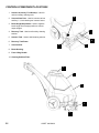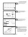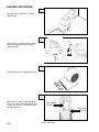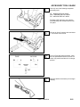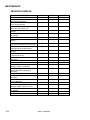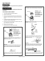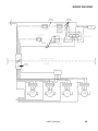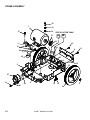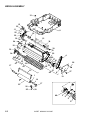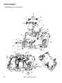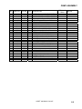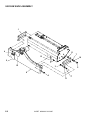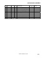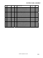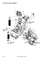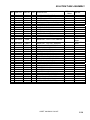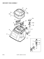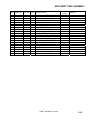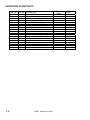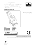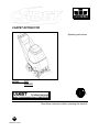
1
CARPET EXTRACTOR
Operating Instructions
MODEL:
CDT7
10080220
C
US
3146518
Read these instructions before operating the machine
AB
86038220 01/20/11
MACHINE DATA LOG/OVERVIEW
MODEL _______________________________________
DATE OF PURCHASE __________________________
SERIAL NUMBER ______________________________
SALES REPRESENTATIVE # _____________________
DEALER NAME ________________________________
OPERATIONS GUIDE NUMBER ___________________
PUBLISHED __________________________________________
YOUR DEALER
Name: __________________________________________________________________________________________________
Address: _______________________________________________________________________________________________
For the name and address of your dealer contact: Windsor Industries
Phone Number: _________________________________________________________________________________________
1
CADET 86038220
TABLE OF CONTENTS
Machine Data Log/Overview.........................1
Table of Contents..........................................2
HOW TO USE THIS MANUAL
How to use this Manual.................................1-1
SAFETY
Important Safety Instructions ........................2-1
Hazard Intensity Level ..................................2-2
Grounding Instructions..................................2-3
OPERATIONS
Technical Specifications. ..............................3-1
Controls/Component Location ......................3-2
Filling Operation............................................3-5
Operations. ...................................................3-6
Cleaning Procedure. .....................................3-8
Accessory Tool Usage. ............................... 3-10
MAINTENANCE
Service Schedule ..............................……… 4-1
Periodic Maintenance. ..................................4-2
Daily/ Regular Maintenance..........................4-2
Vacuum Motor Replacement ........................4-3
Belt Replacement..........................................4-4
Solution Pump Replacement ............……… 4-5
Wiring Diagram. ............................................4-6
Troubleshooting Chart ..................................4-7
GROUP PARTS LIST
Frame Assembly. ........................................ 5-1
Brush Assembly. ......................................... 5-3
Pump Assembly(prior to SN). ..................... 5-5
Pump Assembly .......................................... 5-7
Vacuum Shoe Assembly............................. 5-9
Control Panel Assembly.............................. 5-11
Solution Tank Assembly. ............................ 5-13
Recovery Tank Assembly. .......................... 5-15
Suggested Spare Parts/Notes .................... 5-17
CADET 86038220
2
HOW TO USE THIS MANUAL
This manual contains the following sections:
-
The SAFETY section contains important information
regarding hazard or unsafe practices of the
machine. Levels of hazards is identified that could
result in product or personal injury, or severe injury
resulting in death.
HOW TO USE THIS MANUAL
SAFETY
OPERATIONS
MAINTENANCE
PARTS LIST
The HOW TO USE THIS MANUAL section will tell
you how to find important information for ordering
correct repair parts.
Parts may be ordered from authorized dealers.
When placing an order for parts, the machine model
and machine serial number are important. Refer to
the MACHINE DATA box which is filled out during
the installation of your machine. The MACHINE
DATA box is located on the inside of the front cover
of this manual.
The OPERATIONS section is to familiarize the
operator with the operation and function of the
machine.
The MAINTENANCE section contains preventive
maintenance to keep the machine and its
components in good working condition. They are
listed in this general order:
-
Periodic
Daily/Regular
Troubleshooting
The PARTS LIST section contains assembled parts
illustrations and corresponding parts list. The parts
lists include a number of columns of information:
MODEL _____________________________________
DATE OF PURCHASE ________________________
SERIAL NUMBER ____________________________
-
SALES REPRESENTATIVE # ___________________
-
DEALER NAME ______________________________
OPERATIONS GUIDE NUMBER __________________
-
PUBLISHED ________________________________
The model and serial number of your machine is on
the bottom back-end of the machine.
-
-
REF – column refers to the reference
number on the parts illustration.
PART NO. – column lists the part
number for the part.
PRV NO. - reference number.
QTY – column lists the quantity of the
part used in that area of the machine.
DESCRIPTION – column is a brief
description of the part.
SERIAL NO. FROM – column indicates
the first machine the part number is
applicable to. When the machine design
has changed, this column will indicate
serial number of applicable machine.
The main illustration shows the most
current design of the machine. The
boxed illustrations show older designs.
If column has an asterisk (*), call
manufacturer for serial number.
NOTES – column for information not
noted by the other columns.
NOTE: If a service or option kit is installed on your
machine, be sure to keep the KIT INSTRUCTIONS
which came with the kit. It contains replacement
parts numbers needed for ordering future parts.
NOTE: The number on the lower left corner of the
front cover is the part number for this manual.
1-1
CADET 86038220
SAFETY INSTRUCTIONS
IMPORTANT SAFETY INSTRUCTIONS
When using an electrical appliance, basic precaution
must always be followed, including the following:
READ ALL INSTRUCTIONS BEFORE USING THIS MACHINE.
This machine is for commercial use.
To reduce the risk of fire, electric shock, or injury:
Connect to a properly grounded outlet. See Grounding Instructions.
Do not leave the machine unattended. Unplug machine from outlet when not in use and before maintenance or
service.
Use only indoors. Do not use outdoors or expose to rain.
Do not allow machine to be used as a toy. Close attention is necessary when used by or near children.
Use only as described in this manual. Use only manufacturer’s recommended components and attachments.
Do not use damaged electrical cord or plug. Follow all instructions in this manual concerning grounding the
machine. If the machine is not working properly, has been dropped, damaged, left outdoors, or dropped into
water, return it to an authorized service center.
Do not pull or carry machine by electrical cord, use as a handle, close a door on cord, or pull cord around sharp
edges or corners.
Do not run machine over cord. Keep cord away from heated surfaces.
Do not unplug machine by pulling on cord. To unplug, grasp the electrical plug, not the electrical cord.
Do not handle the electrical plug or machine with wet hands.
Do not operate the machine with any openings blocked. Keep openings free of debris that may reduce airflow.
This machine is intended for cleaning carpet only.
Do not vacuum anything that is burning or smoking, such as cigarettes, matches, or hot ashes.
This machine is not suitable for picking up health endangering dust.
Turn off all controls before unplugging.
Machine can cause a fire when operating near flammable vapors or materials. Do not operate this machine near
flammable fluids, dust or vapors.
This machine is suitable for commercial use, for example in hotels, schools, hospitals, factories, shops
and offices for more than normal housekeeping purposes.
Maintenance and repairs must be done by qualified personnel.
If foam or liquid comes out of machine, switch off immediately.
SAVE THESE INSTRUCTIONS
CADET 86038220
2-1
SÛRETÉ
IMPORTANTES MESURES DE SÉCURITÉ
L’utilisation d’un appareil électrique demande certaines précautions:
LIRE TOUTES LES INSTRUCTIONS AVANT DE FAIRE FONCTIONNER (CET APPAREIL).
! AVERTISSEMENT
Pour réduire les risques d’incendie, de choc électrique ou de blessure:
Cet appareil ne doit être connecter qu a des prises ayant une sortie de terre.
Ne pas laisser l’appareil sans surveillance lorsqu’il est branché. Débrancher lorsque l’appareil n’est pas utilisé et
avant l’entretien.
Pour reduire les risques de choc electrique, ne pas utiliser à l exterieur et ne pas aspirer de matières humides.
Ne pas permettre aux enfants de jouer avec l’appareil. Une attention particulière est nécessaire lorsque l’appareil
est utilisé par des enfants ou à proximité de ces derniers.
N’utiliser que conformément à cette notice avec les accessoires recommandés par le fabricant.
Ne pas utiliser si le cordon ou la fiche est endommagé. Retourner l’appareil à un atelier de réparation s’il ne
fonctionne pas bien, s’il est tombé ou s’il a été endommagé, oublié à l’extérieur ou immergé.
Ne pas tirer soulever ou traîner l’appareil par le cordon. Ne pas utiliser le cordon comme une poignée, le coincer
dans l’embrasure d’unée porte ou l’appuyer contre des arêtes vives ou des coins. Ne pas faire rouler l’appareil
sur le cordon.
Garder le cordon à l’écart des surfaces chaudes.
Ne pas débrancher en tirant sur le cordon. Tirer plutôt la fiche.
Ne pas toucher la fiche ou l’appareil lorsque vos mains sont humides.
N’insérer aucun objet dans les ouvertures. Ne pas utiliser l’appareil lorsqu’une ouverture est bloquée. S’assure
que de la poussière, de la peluche, des cheveux ou d’autres matières ne réduisent pas le débit d’air.
Tenga especial cuidado al manejar la apiradora en una escalera.
Ne pas aspirer de matiéres en combustion ou qui dégagent de la fumée, comme des cigarettes, des allumettes
ou des cendres chaudes.
Cette machine n’est pas adaptée au ramassage de poussières dangereuses.
Mettre toutes les commandes à la position ARRÊT avant de débrancher l’appareil.
Ne pas aspirer des liquides inflammables ou combustibles, comme de l’essence, et ne pas faire fonctionner dans
des endroits où peuvent se trouver de tels liquides.
Cette machine est destinée à un usage commercial. Elle est recommandée davantage pour les domaines
hôtelier, scolaire, hospitalier, industriel ou pour les bureaux, les chaînes de magasin, que pour un usage
domestique normal.
L’entretien et les réparations de la machine doivent être effectuées par un personnel qualifié.
Si de la mousse ou du liquide sort de la machine, la mettre hors tension immédiatement.
CONSERVER CES INSTRUCTIONS
CADET 86038220
2-2
HAZARD INTENSITY LEVEL
The following symbols are used throughout this guide as indicated in their descriptions:
HAZARD INTENSITY LEVEL
There are three levels of hazard intensity identified by signal words -WARNING and CAUTION and FOR
SAFETY. The level of hazard intensity is determined by the following definitions:
! WARNING
WARNING - Hazards or unsafe practices which COULD result in severe personal injury or death.
! CAUTION
CAUTION - Hazards or unsafe practices which could result in minor personal injury or product or property
damage.
FOR SAFETY: To Identify actions which must be followed for safe operation of equipment.
Report machine damage or faulty operation immediately. Do not use the machine if it is not in proper
operating condition. Following is information that signals some potentially dangerous conditions to the
operator or the equipment. Read this information carefully. Know when these conditions can exist. Locate
all safety devices on the machine. Please take the necessary steps to train the machine operating
personnel.
FOR SAFETY:
DO NOT OPERATE MACHINE:
Unless Trained and Authorized.
Unless Operation Guide is Read and understood.
In Flammable or Explosive areas.
In areas with possible falling objects.
WHEN SERVICING MACHINE:
Avoid moving parts. Do not wear loose clothing; jackets, shirts, or sleeves when working on the
machine. Use manufacturer approved replacement parts.
CADET 86038220
2-3
DEGRÉS DE RISQUES EN CAS DE DANGER
Les symboles ci-dessous sont utilisés à travers ce manuel comme illustré dans leurs descriptions :
DEGRÉS DE RISQUES EN CAS DE DANGER
Il existe trois degrés de risques identifiés par les termes signalétiques –AVERTISSEMENT et
ATTENTION et POUR VOTRE SÉCURITÉ. Le degré de risque est défini de la manière suivante :
AVERTISSEMENT - Dangers ou méthodes dangereuses qui POURRAIENT provoquer de graves blessures ou
entraîner la mort.
ATTENTION - Dangers ou méthodes dangereuses qui pourraient provoquer des blessures légères ou une détérioration du produit ou des biens
immobiliers.
POUR VOTRE SÉCURITÉ : ce signe permet d’identifier les mesures de précaution à prendre pour assurer
un bon fonctionnement du matériel.
Rendre compte immédiatement d’une défaillance ou d’une détérioration de la machine. Ne pas utiliser la machine si
celle-ci ne fonctionne pas correctement. Lire soigneusement les informations ci-dessous signalant certains dangers
potentiels pour l’opérateur de la machine. L’opérateur doit être absolument au courant de ces dangers potentiels.
Localiser tous les dispositifs de sécurité sur la machine. Il est conseillé de prendre les mesures nécessaires pour
former le personnel opérateur.
POUR VOTRE SÉCURITÉ :
NE PAS MANOEUVRER LA MACHINE :
Lorsqu’on n’est pas expérimenté ou qualifié.
Lorsque le guide d’utilisation n’est pas été lu ou compris.
Dans des zones inflammables ou explosives.
Dans des zones où des objets peuvent tomber.
LORS DE L’ENTRETIEN DE LA MACHINE :
Éviter les parties amovibles. Ne pas porter de vêtements amples, tels que des vestes, des chemises ou des
vêtements avec manches lors de l’utilisation de la machine. Utiliser les pièces détachées Windsor
homologuées.
2-4
CADET 86038220
GROUNDING INSTRUCTIONS
ELECTRICAL:
In the USA, this machine operates on a standard 15
amp 115V, 60 Hz, A.C. power circuit. The amp,
hertz, and voltage are listed on the data label found
on each machine. Using voltages above or below
those indicated on the data label will cause serious
damage to the motors.
Grounding Pin
GROUNDING CONNECTION
USING AN ADAPTOR
Grounded
Outlet
FIGURE A
EXTENSION CORDS:
If an extension cord is used, the wire size must be at
least one size larger than the power cord on the
machine, and must be limited to 50 feet (15.5m) in
length.
GROUNDING INSTRUCTIONS:
This appliance must be grounded. If it should
malfunction or break down, grounding provides a
path of least resistance for electric current to reduce
the risk of electric shock. This appliance is equipped
with a cord having an equipment-grounding
conductor and grounding plug. The plug must be
inserted into an appropriate outlet that is properly
installed and grounded in accordance with all local
codes and ordinances.
This appliance is for use on a nominal 120-volt
circuit, and has a grounded plug that looks like the
plug in “Fig. A”. A temporary adaptor that looks like
the adaptor in “Fig. C” may be used to connect this
plug to a 2-pole receptacle as shown in “Fig. B”, if a
properly grounded outlet is not available. The
temporary adaptor should be used only until a
properly grounded outlet (Fig. A) can be installed by
a qualified electrician. The green colored rigid ear,
lug, or wire extending from the adaptor must be
connected to a permanent ground such as a
properly grounded outlet box cover. Whenever the
adaptor is used, it must be held in place by a metal
screw.
Tab for Grounding
Screw
Metal Screw
Adaptor
Grounded
Outlet Box
FIGURE B
Adaptor
FIGURE C
Note: Adaptors are not allowed in Canada.
Improper connection of the equipmentgrounding conductor can result in a risk of
electric shock. Check with a qualified electrician
or service person if you are in doubt as to
whether the outlet is properly grounded. Do not
modify the plug provided with the appliance - if it
will not fit the outlet; have a proper outlet
installed by a qualified electrician.
Le raccordement incorrect du conducteur de
terre d'équipement peut entraîner des risques
d'électrocution. Vérifiez auprès d'un électricien
qualifié ou d'un responsable de l'entretien si
vous avez quelque doute que ce soit quant au
raccordement à la terre de votre prise murale. Ne
modifiez pas la fiche fournie avec l'appareil : si
elle ne correspond pas à la prise murale, faites
installer une prise adéquate par un électricien
qualifié. Utilisez-le uniquement sur des
réceptacles protégés GFCI.
CADET 86038220
2-5
TECHNICAL SPECIFICATIONS
POWER TYPE
GENERAL DIMENSIONS/WEIGHT
ELECTRICAL: 115 V, 15 A, 60 HZ
Vacuum shoe: 17” (43.18 cm) cast
aluminum with spring loaded down
pressure
ELECTRIC VACUUM MOTOR: (1) –3 stage, 1.5 hp,
100 cfm (2.80 cubic meters/min.) Waterlift –120” (304
cm)
WHEELS: (2) 10” dia. (25 cm) wheels
by 2”
BRUSH: (1) 15” (38.1 cm.)
WEIGHT: 92lbs. (42kg)
SOLUTION PUMP: 90 PSI, Diaphragm style, internal
bypass
LENGTH: 41” (104 cm)
SOLUTION CAPACITY: 7 gallons (26.5ltr)
HEIGHT: 34” (86.36 cm)
RECOVERY CAPACITY: 7 gallons (26.5ltr)
WIDTH: 17.5” (44.45 cm)
BRUSH SPEED: 1000 rpm
SOLUTION SPRAY: 2 quick change
jets.
POWER CABLE: 50’ (12.7 m) (14
gauge)
34”
(86.36cm)
41”
(104cm)
3-1
17.5”
(44.45cm)
CADET 86038220
CONTROLS/COMPONENT LOCATIONS
1. Main Handle. Used to pull and maneuver
machine.
2. Electrical Cord.
3
3. Pump Switch. Turns on pump and enables
spray.
5
4. Brush/Spray switch. Turns on brush motor
and activates electro-valve to dispense solution
to floor through jets. Intermittent, off, and
continuous settings.
5. Vacuum Motor Switch. Turns on vacuum
motor
6. Brush Motor Circuit Breaker. 6 amp. Breaker
protecting brush motor.
4
1
7. Vacuum Motor Circuit Breaker. 15 amp.
Breaker protecting vacuum motor.
8. Recovery Dump Hose. Facilitates draining
dirty cleaning solution.
7
6
9. Solution Dump Hose. Facilitates draining
excess cleaning solution from solution tank.
2
8
9
CADET 86038220
3-2
CONTROLS/COMPONENT LOCATIONS
1. Solution Accessory Tool Hookup. Used for
various auxiliary cleaning tools.
10
2. Vacuum Hose Door. Used to connect various
auxiliary 1 ½ inch cleaning tool vacuum hoses.
3. Brush Height Adjustment. Used to regulate
brush height from storage position to various
carpet heights.
1
4. Recovery Tank. Used to collect dirty cleaning
solution.
5. Solution Tank. Used to hold cleaning solution.
9
6. Recovery Tank Dome.
2
3
7. Vacuum Shoe.
8. Brush Housing.
9. Front Lifting Handle.
10. Cleaning Solution Filter.
6
4
5
7
8
3-3
CADET 86038220
CONTROLS/COMPONENT LOCATIONS
1. Solution Intake Cover.
2. Vacuum Intake Cover.
3. Float Shut-Off.
4. Clean-Out Opening.
5. Pour Spout.
6. Lift Handle.
6
1
2
4
6
5
3
CADET 86038220
3-4
FILLING OPERATIONS
STEP
1
RECOVERY TANK
Remove recovery
tank
SOLUTION
TANK
STEP
2
FILL LINE
Add water
7 gal.
(26.5 ltr.)
140°F (60°C)
STEP
3
FILLING THE CADET
NOTE: Use clean bucket of water to fill solution tank
7 – 14oz.
(207ml – 414ml)
Add cleaning
chemical
Do not put defoamer, solvents, spotter or
prespray chemicals in the solution tank.
Do not allow water to spill into vacuum motor inlet.
Dry spillage from top of solution tank before
replacing recovery tank.
CHEMICALS
Suitable Chemicals
Alkalis
Detergents
Hydroxides
Soaps
Vinegar
3-5
Non-Compatible Chemicals
Aldehydes
Aromatic Hydrocarbons
SP Butyls
Carbon Tetrachloride
Clorox*
Chlorinated Bleaches
Chlorinated Hydrocarbons
Lysol*
Methyl Ethel Ketone (MEK)
Perchorethylene (perc)
Phenolics
Trichlorethylene
D-Limonene
STEP
4
CADET 86038220
Replace recovery
tank
OPERATIONS
STEP
1
Remove literature from recovery tank. Fill
solution tank (see filling operations,
page3-5).
STEP
2
Plug cord into grounded outlet.
Note: Be sure dome is seated on recovery
tank, and float shut-off is installed correctly.
STEP
3
Adjust brush to proper setting.
Note: For good operation the brush must
skim the carpet. If circuit breaker trips raise
brush to prevent damage to motor or carpet.
STEP
4
Turn on both Vacuum and Pump motor
switches (“ON”=“I”).
1/8in
(3mm)
CORRECT
INCORRECT
PUMP
ON
VACUUM
ON
CADET 86038220
3-6
OPERATIONS
Tip machine back by main handle to move
to starting point.
STEP
5
Lower machine to floor.
STEP
6
Select intermittent or continuous switch
setting to turn on brush and start solution
spray.
The intermittent setting requires the
operator to hold the switch in the “on”
position with the thumb, and is typically
used in small areas where short cleaning
passes are made.
The continuous setting allows the operator
to set the switch in the “on” position with
one touch, and is typically used in large
areas where long cleaning passes are
made.
3-7
STEP
INTERMITTENT
7
CONTINUOUS
CADET 86038220
CLEANING PROCEDURE
1ft.
(30cm)
STEP
1
Start at wall closest to power outlet. Pull
straight back without pushing down on
handle.
STEP
2
Release intermittent setting or turn off
continuous setting on brush/spray switch
approximately 1 foot before ending
cleaning pass.
STEP
3
Push down on handle to raise vacuum
shoe and brush before moving to the next
cleaning pass. Overlap brush contact
area approximately 1inch.
OFF
1in.
(25mm)
SOLUTION
INTAKE COVER
During operation, observe the following: The
STEP Cadet is equipped with clear internal covers to
4
facilitate operator viewing of dirty solution and
vacuum air flow.
During operation, observe the vacuum intake
cover. Large amounts of water or foam entering
the vacuum system can damage the vacuum
motor. If you notice either condition, shut down
the machine immediately. Empty recovery
tank and/or add defoamer to recovery tank.
VACUUM
INTAKE COVER
CADET 86038220
3-8
CLEANING PROCEDURE
STEP
5
Use right side of machine for cleaning
against walls.
STEP
6
After cleaning, turn off all controls, return
brush to storage position and carefully
unplug machine.
OFF
OFF
OFF
STEP
7
To speed drying, use a Windblower™ fan.
STEP
8
Empty recovery tank by releasing dump
hose. Use a hose with cold water to clean
out the recovery tank. Also drain solution
tank after each use.
3-9
RECOVERY
DRAIN
SOLUTION
DRAIN
CADET 86038220
ACCESSORY TOOL USAGE
STEP
1
Use only one of the following acceptable
accessory tools.
HT – 86000610 PRV NO. 89227
DDH – 86000060 PRV NO. 89226
DH – 86031540 PRV NO. 39504
Pull back collar and insert over machine
mounted fitting, then release collar to lock
into place.
STEP
2
STEP
PUMP
VACUUM
ON
3
Lift door on front of vacuum shoe and insert
1 ½ inch hose cuff into hole.
Turn on Pump and Vacuum Switch. Note:
Be sure intermittent/continuous switch is in
center (off) position and brush is in storage
position.
ON
OFF
STEP
4
CADET 86038220
Squeeze handle on accessory tool to begin
cleaning.
3-10
MAINTENANCE
SERVICE SCHEDULE
MAINTENANCE
Check machine for cord damage
Check recovery dome and gasket for
damage and cleanliness
Check brush – should be clean with no
lint or strings attached
Inspect vac shoe for blockage; remove
fibers with coat hanger, etc.
Check hoses for wear, blockages, or
damage
Check handles, switches, and knobs
for damage
Check vac motor intake filter and clean
Run one gallon of water through
system
Clean out recovery tank and check
float valve to make sure it moves freely
Clean out solution tank and remove
and clean vacuum intake screen
Clean outside of all tanks and check for
damage
Run vac motor for at least one minute
to allow motor to dry
Store with dome off tank to allow the
tank to dry
Check all bearings for noise
Check all gaskets for wear and leakage
Check vacuum intake screen for
damage; replace if necessary
Check pump pressure; observe spray
pattern and check with gauge if
necessary
Check and clean solution screen
Check belts for wear and replace as
necessary
Check brush for wear; ensure bristles
are not damaged
Check cables for fraying
Check the spray bar (manifold) for
damage; replace if broken or bent
Check condition of vac shoe and frame
for damage
Check overall performance of machine
Check vac motor carbon brushes
4-1
DAILY
WEEKLY
QUARTERLY
*
*
*
*
*
*
*
*
*
*
*
*
*
*
*
*
*
*
*
*
*
*
*
*
*
CADET 86038220
MAINTENANCE
PERIODIC MAINTENANCE
Twice a month, flush a white vinegar solution (One
quart vinegar to two gallons of water) or antibrowning solution (mixed as directed) through the
extractor. This will prevent build-up of alkaline
residue in the system. If spray jets become clogged,
remove the spray tips, wash them thoroughly, and
blow-dry.
NOTE: Do not use pins, wire, etc. to clean nozzles
as this could destroy spray pattern.
Periodically inspect all hoses, electrical cables and
connections on your machine. Frayed or cracked
hoses should be repaired or replaced to eliminate
vacuum or solution pressure loss. If the cable
insulation is broken or frayed, repair or replace it
immediately. Don’t take chances with electrical fire
or shock.
7. Remove lint and dirt build-up from brush and
housing.
NOTE: Brush removal.
A. To remove brush, grab and pull brush out
from end opposite drive belt (operator’s
right). Remove other end from brush driver.
B. To install brush, line up slots in brush core
with pin in driver on drive belt side
(operator’s left) and push brush onto driver.
Then snap bearing end (opposite end) of
brush into retaining clip.
8. Check cooling air screen (located on frame
behind left wheel) for lint or debris.
9. Check float and shut-off screen and clean as
necessary.
NOTE: Always store machine with brush in “Store”
position.
DAILY / REGULAR MAINTENANCE
Before making any adjustments or repairs to the
machine, disconnect the power cord from electrical
source.
1. Empty unused cleaning solution from the
solution tank.
2. Inspect and clean filter screen in solution tank.
3. Flush pumping system with 4 or 7 liters of clean,
hot water.
4. After each use, rinse tank with fresh water.
Periodically inspect the recovery tank and
decontaminate if necessary, using a Hospital
Grade Virucide or a 1-10 bleach to water
solution. Waste water should be disposed of
properly.
5. Check for and remove any lint or debris around
vac shoe.
6. Check spray jets for full spray pattern.
CADET 86038220
4-2
MAINTENANCE
Only qualified maintenance personnel are to perform the
following repairs.
Vacuum Motor Carbon Brushes Replacement (Ametek)
Seul le personnel d'entretien qualifié peut effectuer des
réparations.
End Cap
VACUUM MOTOR REPLACEMENT
1. Turn off all switches and unplug machine.
2. Remove recovery tank.
3. Remove the (2) screws that fasten the solution tank to
the frame, and tilt tank back to expose the inside of the
frame.
Carbon
Brushes
WARNING: The green
ground wire must be
attached for safe operation.
See wiring diagram.
AVERTISSEMENT : Le fil à
la terre vert doit être attaché
pour un fonctionnement en
toute sécurité. Voir le
schéma de câblage.
4. Locate the vacuum motor wires and disconnect at the
connector. Close the solution tank.
5. Remove the (6) screws holding the vacuum motor cover
(p/n 27809) to the solution tank.
6. Remove the vacuum motor.
Note: When replacing carbon brushes loosen wire terminal
BEFORE removing screws on bracket.
Wire
Terminal
7. Reverse process to install vacuum motor.
Vacuum Motor Carbon Brushes Replacement (Windsor)
End Cap
Carbon
Brushes
WARNING: The green
ground wire must be
attached for safe operation.
See wiring diagram.
AVERTISSEMENT: Le fil à
la terre vert doit être attaché
pour un fonctionnement en
toute sécurité. Voir le
schéma de câblage.
If armature commutator is grooved, extremely pitted or not
concentric, the motor will need to be replaced or sent to a
qualified service center.
Important:
These brushes wear quicker as the length shortens due to
increased heat. Spring inside brush housing will damage
motor if brushes are allowed to wear away completely.
3 [9.5mm]
8
If armature commutator is grooved, extremely pitted or not
concentric, the motor will need to be replaced or sent to a
qualified service center.
Wire Terminal
Important:
These brushes wear quicker as the length shortens due to
increased heat. Spring inside brush housing will damage
motor if brushes are allowed to wear away completely.
3/8 (9.5mm)
Periodically check the length of the carbon brushes. Replace
both carbon brushes when either is less than 3/8" (9.5mm)
long.
4-3
Note:
Place
stop in
groove.
CADET 86038220
Periodically check the length of the carbon brushes. Replace
both carbon brushes when either is less than 3/8" (9.5mm)
long.
MAINTENANCE
Only qualified maintenance personnel are to
perform the following repairs.
Seul le personnel d'entretien qualifié peut
effectuer des réparations.
BELT REPLACEMENT
1. Turn off all switches and unplug machine.
2. Remove recovery tank and brush.
3. Remove the (2) screws that fasten the solution
tank to the frame, and tilt tank back to expose
the inside of the frame.
4. Loosen the (4) screws that hold the brush motor
in place and slide motor forward to release
tension in belt.
5. Remove the (2) screws that fasten the vacuum
shoe links (p/n 05016) to the brush housing.
6. Remove the (3) screws that fasten the side plate
(p/n 62759) to the brush housing to remove belt.
NOTE: All components associated with driving
the brush will come out with the side plate.
7. Reverse process to install belt.
86249420
PRV NO. 62759
86227350
PRV NO. 05016
CADET 86038220
4-4
MAINTENANCE
Only qualified maintenance personnel are to perform the following repairs.
Seul le personnel d'entretien qualifié peut effectuer des réparations.
SOLUTION PUMP REPLACEMENT
1. Turn off all switches and unplug the machine.
2. Remove recovery tank.
3. Remove the (2) screws that fasten the solution tank to the frame, and tilt tank back to expose the
inside of the frame.
4. Remove solution hoses from fittings in pump.
5. Remove the (2) screws that fasten the pump to the frame.
6. Reverse process to install pump.
4-5
CADET 86038220
WIRING DIAGRAM
86268450
PRV NO. 88332
86268830
PRV NO. 88636
86266890
PRV NO. 88655
86004480
PRV NO. 41353
CADET 86038220
4-6
FRAME ASSEMBLY
30
7
19
18
15
SEE SOLUTION TANK
A
21
B
12
33
11
10
3
28
34
31
6
5
22
26
9
32
2
25
27
16
29
8
13
20
5-1
14
4
24
CADET 86038220 03/16/07
FRAME ASSEMBLY
REF
1
2
3
4
5
6
7
8
9
10
11
12
13
14
15
16
17
18
19
20
21
22
23
24
25
26
27
28
29
30
31
32
33
34
PART NO.
86003620
86004340
86001660
86004480
86239610
86026150
86005640
86005810
86198530
86249430
86006020
86250130
86250140
86006580
86273980
86010630
86010660
86010650
86006550
86256190
86259960
86066230
86134490
86253090
86002370
86233140
86274760
86006530
86272160
86276610
86005710
PART NO.
QTY
DESCRIPTION
OPEN
34341
39528
41236
41353
41354
53640
57030
57245
99809
62761
64099
66282
66288
70085
70066
OPEN
87013
87025
87018
70074
73197
OPEN
89506
03107
99667
73943
20035
20041
70271
70057
66052
70697
57105
1
1
2
1
1
1
2
3
2
1
1
6
2
2
2
2
2
2
2
1
2
1
10”
1
1
1
2
2
1
1
3
FRAME, CLP FAMILY
HOSE ASM, 1.5 BLK VAC X 15.5
HUBCAP, 5/8” SHAFT
HARNESS, MAIN, CDT
HINGE, TANK TO FRAME
MOTOR ASM, BRUSH CLP FAMILY
NUT, 10-32 HEX NYLOCK
NUT, 1/4-20 HEX NYLOCK SS
FOAM TAPE, 1/8 THK X 3/4 1SDA
PLATE, BRUSH MTR CLAMP
PULLEY, 1.4 OD, 6GR, MICRO-V
PLUG, HOLE, .375” BLK
PLUG, 9/16 OD BLK NYLON
SCR, 1/4-20 X 1/2 PPHMS SS
SCR, 10-32 X 3/4 PPHMS
WASHER, 1/4 ID X 5/8 OD SS
WASHER, 1/4 LOCK EXT STAR SS
WASHER, #10 X 9/16 OD
SET SCR, 10-32 X 1/4 KCP
STRAIN RELIEF, 90 DEGREE
WHEEL, 1-15/16 X 10” HOOSIER
AXLE, 5/8 X 17.06L
HEAT SHRINK, 3/4 ID UL/CSA
SEAL, FRAME/TANK
CLAMP, 7/16 DIA NYLON UL
CLAMP, 2.0” WORM GEAR
SCR, 1/4-20 X ½ HHCS PLTD
SCR, 1/4-20 X 1 PPHMS SS
PIN, ROLL 1/8” X 1.0”L
SCR, 1/4-20 X 1.25 PPHMS SS
NUT, 1/4-20 HEX W/ STAR WASHER
CADET 86038220 03/16/07
SERIAL NO.
FROM
NOTES:
100046610
5-2
BRUSH ASSEMBLY
31
15
25
11
7
25
29
30
8
16
12
26
24
38
18
16
30
39
10
22
34
4
44
45
36
40
37
33
47
41
26
32
17
28 35
3
43
21
13
42
27
6
1
19
14
17
23
20
30
25
29
25
46
3
9
2
5
5-3
CADET 86038220 03/16/07
BRUSH ASSEMBLY
REF
PART NO.
PRV NO.
QTY
DESCRIPTION
1
2
3
4
5
6
7
8
9
10
11
12
13
14
15
16
17
18
19
20
21
22
23
24
25
26
27
28
29
30
31
32
33
34
35
36
37
38
39
40
41
42
43
44
45
46
47
86000730
86227100
86000900
86001100
86001140
86001300
86001310
86003620
86004060
86004470
86004980
86093080
86005110
86005120
86005130
86005640
86005850
86249410
86249420
86264700
86250680
86006220
86006430
86006510
86006590
86006650
86006700
86275530
86010640
86010650
86007030
86230620
86251710
86003070
86003370
86278130
86272770
86272510
86008650
86008160
86006030
86003390
86001140
86227150
86228890
86028010
86004750
03110
04084
09019
11045
12514
140343
140351
34341
36192
41345
50998
51311
51312
51314
51317
57030
57271
62758
62759
62762
64098
66192
67411
70043
70088
70177
70232
70497
87016
87018
70675
12524
67467
27805
29157
70737
67094
66310
80604
73966
64102
29208
12514
05158
09137
47383
47416
1
1
2
1
1
1
1
REF
2
1
1
1
1
2
1
4
2
1
1
2
1
1
1
2
6
7
2
2
4
6
4
1
1
1
1
1
1
2
2
1
1
1
1
1
2
1
REF
AXLE, ROLLER
ADAPTER, BRUSH BRG.
BEARING, 1.125ODX.500IDX.375
BELT, 180J6 MICRO-V
BRUSH, 15L X 3.38OD
BRKT, BRUSH PULLEY
BRKT, BRUSH HEIGHT
FRAME, CLP FAMILY
GUARD, THREAD
HOUSING, BRUSH 15"
LABEL, BRUSH HEIGHT
LINKAGE, ASM, BRUSH HEIGHT
LINKAGE ASM, ROLLER SUPPORT
LINK, ROLLER, FRONT
LEVER, HEIGHT ADJUSTMENT
NUT, 10-32 HEX NYLOCK
NUT, 3/8 DIA CAP, TYPE PUSH PLT
PLATE, BRUSH HOUSING RH
PLATE, BRUSH HOUSING LH
PLATE, AXLE RETAINER
PULLEY, 2.2 OD, 6GR, MICRO-V
PIN, ROLL 1/4 X 1.25L
ROLLER, 1.9 DIA X 10.5 LG
SCR, 10-32 X 5/8 PFHMS
SCR, 10-32 X 1/2 PPHMS SS DL
SCR, 10-32 X 1/2 FHMS SS
SCR, 10-32 X 3/8 FHMS SS
SCR, #10-24 X 1/2 SHCS
WASHER, #10 LOCK EXT STAR SS
WASHER, #10 X 9/16 OD
SCR, 1/4-20 X.5/8 THMS PLTD NP
BRUSH, 15 L X 3.35 OD G2
RING, TOLERANCE 7/8
CLIP, BEARING
DRIVER, BRUSH
SHLDR BOLT, 3/8 OD X 3/8 L SS NP
RING, 1/2 EXT. SNAP
PIN, CLEVIS 1/4 X 1/2 PLTD
COTTER, 1/4" RING
SPACER, .81ID X 1.06OD, ALUM
PULLEY ASM, BRUSH
DRIVER ASM, BRUSH
BRUSH ASM, 15 IN
ADAPTER, BRUSH BRG. DIE CAST
BEARING, R6 3/8 ID
BRUSH BEARING ASM.
KIT, BRNG/ADPTR EXTRCTR
CADET 86038220 03/16/07
SERIAL NO.
FROM
NOTES:
1000090563
1000090563
1000090563
1000090563
1000090563
5-4
PUMP ASSEMBLY
PRIOR TO SERIAL NO. 1000166663
14
3
20
13
4
10
16
9
2
8
16
21
23
18 1
12
19
15
20
11
17
7
25
26
28
C
6
(SEE SOLUTION 5
TANK)
26
5-5
24
27
CADET 86038220 03/16/07
PUMP ASSEMBLY
REF
PART NO.
PRV NO.
QTY
1
2
3
4
5
6
7
8
9
10
11
12
13
14
15
16
17
18
19
20
21
22
23
24
25
26
27
28
86002470
86002480
86003470
86003480
86004570
86004580
86005640
86026380
86250140
86006830
86273750
86003640
86008370
86026940
86010810
86010650
86010820
86005590
86005580
86003500
86274290
22072
22090
31072
31073
44067
44068
57030
65200
66288
70386
70011
34355
78420
84160
87191
87018
87192
56014
56012
31076
70162
880278
39529
39530
39531
73963
39591
1
2
1
1
2
2
2
1
2
2
2
1
1
1
2
4
2
1
1
2
2
1
1
1
3
1
1
86267400
86281890
86004350
86281900
86253020
86004400
DESCRIPTION
COUPLING, 1/4 ANCHOR W/1" HEX
CONNECTOR, 1/8FPT X 1/4 TUBEQC
ELBOW, SWIVEL, 1/4MPTX1/4TUBE
ELBOW, SWIVEL,1/4MPTX3/8TUBEQC
JET BODY, MINI PROMAX BODY
JET, MINI PROMAX 9504
NUT, 10-32 HEX NYLOCK
PUMP ASM, 115V 73 PSI W/CONN
PLUG, 9/16 OD BLK NYLON
SCR, 10-32 X 1.0 PPHMS
SCR, 1/4-20 X 5/8 HHCS SS
FITTING,1/4 TUBE,"Y", QC
TEE, 1/4 MPT X 3/8 TUBE, QC
VALVE ASM,SOLENOID CLP FAMILY
WASHER, 1/4"IDX1.0OD. FLAT SS
WASHER, #10 X 9/16 OD
WASHER, 7/16 X 3/4 X .19RUBBER
NIPPLE, 1/4 CLOSE
NIPPLE, 1/4 FPT QD
ELBOW, 1/4 MPT X 3/8 TUBE, QC
SCR, 10-32 X 3/8 PPHMS SS
OPEN
WIRE, 22" GRN/18 76011 X 76011
HOSE, 3/8 URETHANE X 29"
HOSE, 3/8 NYLON X 6"
HOSE, 1/4 URETHANE X 6"
SCREEN, INTAKE
HOSE, 3/8 ID NYL11 YLW X 29”
CADET 86038220 03/16/07
SERIAL NO.
FROM
NOTES:
1000029065
1000046610
5-6
PUMP ASSEMBLY
FROM SERIAL NO: 1000166663
14
3
20
8
4
13
10
16
9
2
16
21
23
18
1
12
19
15
20
11
17
7
26
28
29
29
28
C
(SEE SOLUTION
TANK)
26
5-7
24
27
CADET 86038220 03/16/07
6
5
PUMP ASSEMBLY
REF
PART NO.
PRV NO.
QTY
1
2
3
4
5
6
7
8
9
10
11
12
13
14
15
16
17
18
19
20
21
22
23
24
25
26
27
28
29
86032470
86002480
86003470
86003490
86004570
86004580
86005640
86026410
86250140
86274410
86273750
86003640
86008360
86258900
86010810
86010650
86010820
86247750
86234560
86003500
86006590
22072
22090
31072
31074
44067
44068
57030
65257
66288
70195
70011
34355
78419
84179
87191
87018
87192
56055
22097
31076
70088
OPEN
880278
39720
OPEN
39531
73963
39721
29277
1
2
1
1
2
2
2
1
2
2
2
1
1
1
2
4
2
1
1
2
2
1
1
3
1
2
2
86267400
86282340
86281900
86253020
86282350
86279930
DESCRIPTION
SERIAL NO.
FROM
NOTES:
COUPLING, 1/4 ANCHOR W/1" HEX
CONNECTOR, 1/8FPT X 1/4 TUBEQC
ELBOW, SWIVEL, 1/4MPTX1/4TUBE
ELBOW, SWIVEL, 3/8MPTX3/8TUBEQC
JET BODY, MINI PROMAX BODY
JET, MINI PROMAX 9504
NUT, 10-32 HEX NYLOCK
PUMP ASM, 120V SHURFLO
PLUG, 9/16 OD BLK NYLON
SCR, 10-32 X 1.25 PPHMS SS
SCR, 1/4-20 X 5/8 HHCS SS
FITTING,1/4 TUBE,"Y", QC
TEE, 3/8 MPT X 3/8 TUBE, QC
VALVE ASM, 120V CLP FAMILY
WASHER, 1/4"IDX1.0OD. FLAT SS
WASHER, #10 X 9/16 OD
WASHER, 7/16 X 3/4 X .19RUBBER
NIPPLE, 1/4 BSPT X 1/4 NPT HEX
COUPLER, 1/4 FPT X MINI QC
ELBOW, 1/4 MPT X 3/8 TUBE, QC
SCR, 10-32 X 1/2 PPHMS SS
WIRE, 22" GRN/18 76011 X 76011
HOSE, 3/8 OD X 1/4 ID URTHN X 22"
HOSE, 1/4 ID NYLON X 5"
SCREEN, INTAKE
HOSE, 3/8 ID NYLON YLW X 17”
DUCT, 1/2 ID SPLT FLX X 16”
CADET 86038220 03/16/07
5-8
VACUUM SHOE ASSEMBLY
1
4
11
7
13
10
2
12
3
5
8
6
7
11
5-9
CADET 86038220 03/16/07
VACUUM SHOE ASSEMBLY
REF
PART NO.
PRV NO.
QTY
1
2
3
4
5
6
7
8
9
10
11
12
13
86227350
86234760
86005810
86006790
86275120
86006840
86008130
86010620
05016
27674
57245
70351
70360
70390
73958
85039
OPEN
87013
87074
35171
73955
4
1
4
2
4
4
8
1
4
8
1
2
86010630
86010700
86003780
86008120
DESCRIPTION
SERIAL NO.
FROM
NOTES:
ARM, VAC SHOE PARALLEL
COVER, ACCESSORY PORT
NUT, 1/4-20 HEX NYLOCK SS
SCR, 10-32 X 3/8 HHTR W/STAR
SCR, 1/4-20 X.75 PPHMS PHIL
SCR, 1/4-20 X 1 FHCS PLTD
SPACER, 3/8ODX.058WX.2814,CRS
VAC SHOE, 15"
WASHER, 1/4 ID X 5/8 OD SS
WASHER, WAVE 3/8ID X3/4D X.125
GASKET, ACCESSORY PORT
SPRING, EXT .38D X2.75L X.055W
CADET 86038220 03/16/07
5-10
CONTROL PANEL ASSEMBLY
22
12
16
8
11
2
4
21
7
4
1
17
18
3
6
14
23
9
10
19
13
15
5
20
D
SEE SOLUTION
TANK
5-11
CADET 86038220 03/16/07
CONTROL PANEL ASSEMBLY
REF
PART NO.
PRV NO.
QTY
DESCRIPTION
1
2
3
4
5
6
7
8
9
10
11
12
13
14
15
16
17
18
19
20
21
22
23
86001240
86001980
86230210
86002010
86234320
86005670
86005760
86064400
86006950
86006710
86007120
86007140
86256240
86010800
86004480
86242720
86010750
86005700
86006830
86234110
86242400
86242410
86245040
14020
14700
14832
14942
23679
57040
57116
61348
70532
70235
72126
72130
73505
87189
41353
500180
87100
57104
70386
23086
500077
500078
50279
1
1
1
2
1
2
2
1
9
2
1
2
1
9
REF
1
2
3
1
1
1
1
1
TERMINAL BLOCK, 115V (3-4-3)
BREAKER, 15A 250VAC 50VDC
BREAKER, 6A VDE CIRCUIT
BOOT, 3/8 CIRCUIT BREAKER
CORD ASM, 14/3 X 22" YLW
NUT, 1/2 NPT CONDUIT
NUT, 6-32 W/STAR WASHER PLTD
PANEL, CADET CONTROL
SCR, 10-32 X 1/2 PPHMS BLK NP
SCR, 6-32 X 1.0 PH BLK NYLON
SWITCH, DPDT 3-POSITION ROCKER
SWITCH, SPST 2-POSITION ROCKER
STRAIN RELIEF, 1/2 NPT TRUMPET
WASHER, .2IDX.500 BLK SS
HARNESS, MAIN, CDT
LABEL, CONTROL PANEL, CDT
WASHER, 3/8 ID INT.LOCK THIN
NUT, 10-32 W/STAR WASHER PLTD
SCR, 10-32 X 1.0 PPHMS
CORD SET,14/3 SJTW-A X 50' YLW
LABEL, CIRCUIT BREAKER BRUSH
LABEL, CIRCUIT BREAKER VAC
LABEL, GROUND SYMBOL
CADET 86038220 03/16/07
SERIAL NO.
FROM
NOTES:
1000032157
5-12
SOLUTION TANK ASSEMBLY
6
29
3
18
32
30*
7
24
33
25
13
13A
13B
10
16*
23
D
17
SEE CONTROL
PANEL
7*
15
12
18
A
21
SEE FRAME
ASM
22
34
11*
8
9
19*
2
28*
20 27*
1
B
SEE FRAME
ASM
5*
26*
4
C
SEE PUMP ASM
18
14
5-13
CADET 86038220 03/16/07
SOLUTION TANK ASSEMBLY
REF
PART NO.
PRV NO.
QTY
DESCRIPTION
1
2
3
4
5
6
7
8
9
10
11
12
13
86233140
86233150
86003080
86003090
86235500
86003790
86003920
86281880
86240009
86004340
86001590
86240980
86026880
20041
20042
27809
27810
31081
35175
35231
39526
39527
39528
40049
41348
53789
3
1
1
1
1
2
2
1
1
REF
1
1
1
CLAMP, 2.0" WORM GEAR
CLAMP, 3/8 HOSE (D-SLOT)
COVER, VAC MOTOR
COVER, BELT
ELBOW, 3/8 MPT X 3/8 TUBE, PLASTIC
GASKET, TANK TO VAC COVER
GASKET, VAC COVER (CLP FAMILY)
HOSE,1/2 CLEAR X 12
HOSE, 1.5 BLK VAC X 3.0
HOSE ASM, 1.5 BLK VAC X 15.5
HOSEBARB, 3/8MPT X 1/2 NYLON
HOUSING, VAC MOTOR
VAC MOTOR ASM, CLP FAMILY
13A
86135340
14258
BRUSH SET, 120V 5.7 VAC, AMETEK
13B
86135320
140687
BRUSH SET, 120V VAC, WINDSOR
14
15
16
17
18
19
20
21
22
23
24
25
26
27
28
29
30
31
32
33
34
86006600
86006590
86032240
86259060
86010650
86007970
86010630
86006580
86078950
86233260
86272840
86256170
86003950
86003960
86003970
86275690
86003940
86026660
86002870
86232280
86177090
70114
70088
75257
85037
87018
73864
87013
70085
20035
20092
67147
73169
35236
35237
35238
70525
35235
75276
27417
500012
03-000261
2
2
1
1
10
1
3
3
2
1
1
1
1
1
1
6
1
1
1
1
1
SCR, #10 X 3/4 PPHST TYPE B
SCR, 10-32 X 1/2 PPHMS SS
TANK, CDT SOLUTION
VENT, COOLING AIR SMALL
WASHER, #10 X 9/16 OD
STRAINER, 3/8 IN. NPT 60 MESH
WASHER, 1/4 ID X 5/8 OD SS
SCR, 1/4-20 X 1/2 PPHMS SS DL
CLAMP, 7/16 DIA NYLON UL
CLAMP, 3.5" WORM GEAR
RING, 2" DIA SPLIT
STRAIN RELIEF, CORD HOOK
GASKET, TANK, L-F
GASKET, TANK, L-R
GASKET, TANK, RH
SCR, #10 X 1.0 PPHST TYPE B
GASKET, CDT PANEL
TANK ASM, SOLUTION CDT7
CORD, 99807 1/8 X 12"
CARD, INSTRUCTION CDT7
CLAMP, CABLE 1/2 ID 1/4BLT
CADET 86038220 03/16/07
SERIAL NO.
FROM
*
*
NOTES:
SERVICE
ONLY
SERVICE
ONLY
1000032157
* ITEMS
5-14
RECOVERY TANK ASSEMBLY
16
15
5
E
18
7
11A
4
12
8
10A
E
1A
14A
9
12
13
17
2
6
11B
3
10B
1B
14B
12
5-15
CADET 86038220 03/16/07
RECOVERY TANK ASSEMBLY
REF
PART NO.
PRV NO.
QTY
1A
1B
2
3
4
5
6
7
8
9
10A
10B
11A
11B
12
13
14A
14B
15
16
17
18
86002400
86002350
86233140
86008400
86003110
86235280
86003630
86003910
86003930
86004200
86004510
86004450
86004500
86006240
86006600
86032250
8001370
86001190
86002870
86242230
86245940
86003330
20064
20002
20041
78499
27816
28060
34351
35230
35232
39353
41391
40019
41390
66227
70114
75258
140408
140133
27417
500009
50995
28061
1
1
1
1
2
1
1
1
2
1
1
1
1
1
6
1
1
1
1
1
1
1
DESCRIPTION
CLAMP, 2.0" WORM GEAR X .312
CLAMP, 2.0” WORM GEAR
CLAMP, 2.0" WORM GEAR
CORD, DRAIN HOSE
COVER, REC. TANK
DOME, CLP FAMILY
FLOAT SHUT-OFF
GASKET, DOME
GASKET, PORT COVER
HOSE, 1.5 X 12.0 DRAIN
HOSE, INSERT
HOSEBARB, 1.5 DOUBLE MCHD
HOSE, CAP
PLUG, DRAIN HOSE
SCR, #10 X 3/4 PPHST TYPE B
TANK, CDT RECOVERY
BRKT, HOSE HOOK
BRKT, RECOVERY HOSE MTG
CORD, 99807 1/8 X 12"
LABEL, WARNING
LABEL, CADET MAIN
DOME ASM, CLP FAM
CADET 86038220 03/16/07
SERIAL NO.
FROM
1000083443
NOTES:
1000083443
1000083443
1000083443
5-16
SUGGESTED SPARE PARTS
5-17
PART NO.
PRV NO.
86001140
86001100
86000900
86004570
86004580
86026410
86258900
86003780
86001980
86230210
86007140
86007120
86026880
86007970
86003630
86003330
86006240
86135340
86135320
12514
11045
09019
44067
44068
65257
84179
35171
14700
14832
72130
72126
53789
73864
34351
28061
66227
14258
140687
DESCRIPTION
BRUSH, ASM, 15 IN
BELT, 180J6 MICRO-V
BEARING, 1.125ODX.500IDX.375
JET BODY, MINI PROMAX BODY
JET, MINI PROMAX 9504
PUMP ASM, 120V SHURFLO
VALVE ASM, 120V CLP FAMILY
GASKET, ACCESSORY PORT
BREAKER, 15A 250VAC 50 VDC
BREAKER, 6A VDE CIRCUIT
SWITCH, SPST 2-POSITION ROCKER
SWITCH, DPDT 3-POSITION ROCKER
VAC MOTOR ASM, CLP FAMILY
STRAINER, 3/8 IN. NPT 60 MESH
FLOAT, SHUT-OFF
DOME ASM, CLP FAM
PLUG, DRAIN HOSE
BRUSH SET, 120V 5.7 VAC, AMETEK
BRUSH SET, 120V VAC, WINDSOR
CADET 86038220 03/16/07
SERIAL #
FROM
1000166663
1000166663
*
*
NOTES: