1
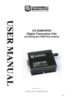
USER GUIDE 9522B & COM9522B Iridium Data Modem Issued: 16.7.13 Copyright © 2009-2012 Campbell Scientific (Canada) Corp. Printed under licence by Campbell Scientific Ltd CSL 1003 Guarantee This equipment is guaranteed against defects in materials and workmanship. This guarantee applies for twelve months from date of delivery. We will repair or replace products which prove to be defective during the guarantee period provided they are returned to us prepaid. The guarantee will not apply to: • Equipment which has been modified or altered in any way without the written permission of Campbell Scientific • Batteries • Any product which has been subjected to misuse, neglect, acts of God or damage in transit. Campbell Scientific will return guaranteed equipment by surface carrier prepaid. Campbell Scientific will not reimburse the claimant for costs incurred in removing and/or reinstalling equipment. This guarantee and the Company’s obligation thereunder is in lieu of all other guarantees, expressed or implied, including those of suitability and fitness for a particular purpose. Campbell Scientific is not liable for consequential damage. Please inform us before returning equipment and obtain a Repair Reference Number whether the repair is under guarantee or not. Please state the faults as clearly as possible, and if the product is out of the guarantee period it should be accompanied by a purchase order. Quotations for repairs can be given on request. It is the policy of Campbell Scientific to protect the health of its employees and provide a safe working environment, in support of this policy a “Declaration of Hazardous Material and Decontamination” form will be issued for completion. When returning equipment, the Repair Reference Number must be clearly marked on the outside of the package. Complete the “Declaration of Hazardous Material and Decontamination” form and ensure a completed copy is returned with your goods. Please note your Repair may not be processed if you do not include a copy of this form and Campbell Scientific Ltd reserves the right to return goods at the customers’ expense. Note that goods sent air freight are subject to Customs clearance fees which Campbell Scientific will charge to customers. In many cases, these charges are greater than the cost of the repair. Campbell Scientific Ltd, Campbell Park, 80 Hathern Road, Shepshed, Loughborough, LE12 9GX, UK Tel: +44 (0) 1509 601141 Fax: +44 (0) 1509 601091 Email: [email protected] www.campbellsci.co.uk PLEASE READ FIRST About this manual Please note that this manual was originally produced by Campbell Scientific Inc. primarily for the North American market. Some spellings, weights and measures may reflect this origin. Some useful conversion factors: Area: 1 in2 (square inch) = 645 mm2 Length: 1 in. (inch) = 25.4 mm 1 ft (foot) = 304.8 mm 1 yard = 0.914 m 1 mile = 1.609 km Mass: 1 oz. (ounce) = 28.35 g 1 lb (pound weight) = 0.454 kg Pressure: 1 psi (lb/in2) = 68.95 mb Volume: 1 UK pint = 568.3 ml 1 UK gallon = 4.546 litres 1 US gallon = 3.785 litres In addition, while most of the information in the manual is correct for all countries, certain information is specific to the North American market and so may not be applicable to European users. Differences include the U.S standard external power supply details where some information (for example the AC transformer input voltage) will not be applicable for British/European use. Please note, however, that when a power supply adapter is ordered it will be suitable for use in your country. Reference to some radio transmitters, digital cell phones and aerials may also not be applicable according to your locality. Some brackets, shields and enclosure options, including wiring, are not sold as standard items in the European market; in some cases alternatives are offered. Details of the alternatives will be covered in separate manuals. Part numbers prefixed with a “#” symbol are special order parts for use with non-EU variants or for special installations. Please quote the full part number with the # when ordering. Recycling information At the end of this product’s life it should not be put in commercial or domestic refuse but sent for recycling. Any batteries contained within the product or used during the products life should be removed from the product and also be sent to an appropriate recycling facility. Campbell Scientific Ltd can advise on the recycling of the equipment and in some cases arrange collection and the correct disposal of it, although charges may apply for some items or territories. For further advice or support, please contact Campbell Scientific Ltd, or your local agent. Campbell Scientific Ltd, Campbell Park, 80 Hathern Road, Shepshed, Loughborough, LE12 9GX, UK Tel: +44 (0) 1509 601141 Fax: +44 (0) 1509 601091 Email: [email protected] www.campbellsci.co.uk Contents PDF viewers note: These page numbers refer to the printed version of this document. Use the Adobe Acrobat® bookmarks tab for links to specific sections. 1. Overview ...................................................................... 1 1.1 1.2 1.3 1.4 1.5 General Description and Modes of Operation .......................................... 1 Modem Models and Accessories .............................................................. 1 Hardware Overview .................................................................................. 2 Control ...................................................................................................... 3 Where it works .......................................................................................... 4 2. Specifications ............................................................. 4 2.1 9522B Specifications ................................................................................ 4 2.2 COM9522B Specifications ....................................................................... 5 3. Iridium SIM card & Modem Setup .............................. 5 3.1 Iridium SIM Card Use .............................................................................. 5 3.2 Setup of Iridium Modems ......................................................................... 5 3.2.1 Step 1: Hardware Connections ........................................................ 5 3.2.2 Step 2: Start Hyperterminal ............................................................. 6 3.2.3 Step 3¨Hyperterminal Connection Type ......................................... 6 3.2.4 Step 4: Hypterterminal Port settings ............................................... 7 3.2.5 Step 5: Configuring Port Settings ................................................... 8 3.2.6 Step 6: Hyperterminal Communications ......................................... 8 4. Datalogger Configuration ......................................... 11 5. LoggerNet Configuration.......................................... 12 5.1 Setup of Loggernet Communications ...................................................... 12 5.1.1 Step 1: LoggerNet Setup ............................................................... 12 5.1.2 Step 2: Comport Configuration .................................................... 13 5.1.3 Step 3: Generic Modem Configuration ......................................... 14 5.1.4 Step 4: Generic Modem Configuration Continued ........................ 15 5.1.5 Step 5: PakBusPort Configuration ................................................ 16 5.1.6 Step 6: CR1000 Configuration ....................................................... 17 6. Remote Modem Configuration ................................. 19 6.1 Program Example 1................................................................................. 19 6.2 Program Example 2................................................................................. 19 7. Troubleshooting Tools and Tips.............................. 21 10.1 Example CS120 message outputs ......................................................... 20 i Appendix A. Sample Data Transfer Calculations....................... A-1 B. Hardware Installation ............................................. B-1 B.1 SIM Card Installation .......................................................................... B-1 B.2 Antenna Installation ............................................................................. B-2 B.3 9522B Modem Installation ................................................................. B-4 C. Unlocking a SIM Card ............................................ C-1 C.1 Handset Method................................................................................... C-1 C.2 Terminal Emulator Method ................................................................. C-1 D. Interfacing Loggernet to RUDICS .......................... D-1 D.1 D.2 D.3 D.4 Base Station System Requirements ..................................................... D-1 Remote Station Requirements ............................................................. D-1 Serial Port Redirector .......................................................................... D-1 Loggernet Setup .................................................................................. D-3 D4.1 Step 1: ComPort Configuration .................................................. D-3 D4.2 Step 2: Generic Modem Configuration....................................... D-4 Tables 1. Equipment List for Base and Remote Stations ........................................... 2 2. Remote Station COM95522B Wiring ........................................................ 2 3. Base Station COM9522B Wiring ............................................................... 3 Figures 1. 9522B Base Station Configuration ............................................................. 3 2. 9522B Remote Station RS232 Configuration ............................................ 3 3. 9522B Remote Station CS I/O Configuration ............................................ 4 4. Starting a Hyperterminal Session ............................................................... 6 5. Hyperterminal Connection Type ................................................................ 6 6. Hyperterminal ComPort Connection .......................................................... 7 7. Hyperterminal Port Settings ....................................................................... 7 8. Port Settings Configures ............................................................................. 8 9. Hyperterminal Screen ................................................................................. 9 10. CR1000 AT Command String .................................................................. 9 11. Modem Reply to Command String ......................................................... 10 12. Modem Setting Confirmation ................................................................. 10 13. Device Configuration Utility .................................................................. 11 14. ComPorts Settings Tab ........................................................................... 12 15. LoggerNet Setup Tree ............................................................................ 13 16. ComPort Configuration .......................................................................... 14 17. Generic – Hardware Configuration ........................................................ 15 18. Generic – Modem Configuration............................................................ 16 19. PakBus Port Configuration..................................................................... 17 ii 20. 21. 22. 23. 24. 25. 26. 27. 28. 29. 30. 31. 32. 33. 34. CR1000 Hardware Configuration ........................................................... 18 CR1000 Schedule Configuration ............................................................ 18 SIM Card Housing ................................................................................ B-1 SIM Card Slot ....................................................................................... B-1 Installed SIM Card ................................................................................ B-2 Antenna Mount and Cabling ................................................................. B-2 Antenna and Cable Connected .............................................................. B-3 Antenna Attached to Mount .................................................................. B-3 Antenna Mounted on Crossarm............................................................. B-3 Serial Port Redirector Setup .................................................................D-2 Serial Port Redirector Setup (cont’d) ....................................................D-2 Serial Port Redirector Setup (cont’d) ....................................................D-3 ComPort Configuration .........................................................................D-3 Generic Modem Configuration .............................................................D-4 Generic Modem Configuration (cont’d) ...............................................D-5 iii 9522B & COM9522B Iridium Data Modem 1. Overview 1.1 General Description and Modes of Operation The Iridium satellite network consists of a constellation of 66 satellites situated in six planes in low-earth orbit. Each plane is populated by 11 satellites in polar orbits, giving the Iridium network excellent coverage in high latitudes that equatorial satellites often cannot reach. Iridium provides 5 different services: dial-up data, Short Burst Data (SBD), Short Messaging Service (SMS), Internet Connection, and Router Based Unrestricted Digital Internetworking Connectivity Solution (RUDICS). For the purposes of this manual we will discuss dial-up data and RUDICS as the preferred methods of connecting with Campbell Scientific dataloggers. Contact Campbell Scientific if you wish to send SBD messages as this is possible under datalogger program control. 1.2 Modem Models and Accessories The Iridium Satellite System used with Campbell Scientific consists of the 9522B modem, COM9522B Interface Module kit, data cables, antenna and power supply. The base and remote stations utilize the same modem type, which both require a change to their configuration. The recommended connection of the remote modem to dataloggers, when possible is via the RS232 port. It is possible to communication with a datalogger via either the CSI/O port or COM Ports 1-4. All datalogger connections will require appropriate cabling and interface accessories (See Table 1). The COM9522B is required to connect the modem to the datalogger or computer and an appropriate power source. For remote applications where AC power is not available it is recommended to operate the modem on a schedule to avoid discharging the battery power supply. The antenna used for both Iridium modems is supplied. For best signal reception the antenna should be mounted so that it has an unobstructed view of the sky and horizon. Reception quality changes as satellites move overhead so it is critical that the view be clear. See Section 7 of this manual for information about checking signal quality. The antenna mounts to a ¾” diameter pipe which can be connected to a horizontal arm using a nu-rail connector. The nu-rail connector used will depend on the type of horizontal pipe. 008158 is suitable for the CM200 series arms. 1 9522B & COM9522B Iridium Data Modem Table 1. Equipment List for Base and Remote Stations Base Station Remote Station 9522B L-Band Data Modem 9522B L-Band Data Modem MB3 Mounting Kit (optional) Iridium antenna plus cable Iridium antenna plus cable COM9522B COM9522B Iridium SIM card (comes with modem) 9876-001 Null Modem Cable (1ft lead) SC932A with an extra SC12 (Only required if using CSI/O port of datalogger) Iridium SIM card (comes with modem) SC110 9-pin male DTE to bare leads (Only required if using a datalogger COM Port) 1.3 Hardware Overview Table 1 lists the hardware typically used for both a Base and Remote station. Tables 2 and 3 list common wiring for both the remote and base stations. Figures 1 to 3 represent the typical configurations of the Base and Remote stations. Please refer to Appendix B for a thorough description of the installation procedure for both the Base and Remote stations. WARNING Be sure that the antenna is connected to either of the modems before applying power, as damage to the equipment may occur. Table 2. Remote Station COM9522B Wiring Hardware ComPort Description Colour Antenna 9522B COM9522B Interface Power Control Yellow Ground Modem Power Serial Communications “DCE Device” “Datalogger” Black Red 9876-001 SC12 SC12 COM9522B 2 9876-001 RS232 SC932A (optional) CS I/O Connection “ANT” SMA connector to antenna cable using C2626 adaptor 26-pin ribbon cable connector Control Port Datalogger (5V power trigger) G – Datalogger +12V (Direct to Station Power Supply) 9-pin connector of COM9522B 9-pin connector of COM9522B CS I/O port of Datalogger User Guide Table 3. Base Station COM9522B Wiring Hardware ComPort Description RS232* Antenna COM9522B Interface Power Control Ground Modem Power Serial Communications 9522B COM9522B 008085 Colour Connection Yellow Black Red 008085 “ANT” SMA connector to antenna cable 26-pin ribbon cable connector +12V (Direct to Station Power Supply) G – Datalogger +12V (Direct to Station Power Supply) Connect to PC *A USB to serial adaptor such as part 010777 can be used to connect a PC directly to the serial port for either configuration or use as a base station. 1.4 Control The COM9522B is used to control power to the modem with the use of 5Vdc signal from a datalogger control port (ex. C1: Yellow wire). It is possible to power the modem/interface via the datalogger wiring panel. However, it is recommended that the COM9522B is wired directly from a 12Vdc power supply (power +: Red, power -: Black) 008085 Figure 1. 9522B Base Station Configuration 9876-001 Figure 2. 9522B Remote Station RS232 Configuration 3 9522B & COM9522B Iridium Data Modem SC12 Figure 3. 9522B Remote Station CS I/O Configuration 1.5 Where it works Unlike other satellite systems the Iridium satellite system is located in a low polar orbit, giving the system complete global coverage. Their relatively low altitude (780 km) means that they are situated close to transmitting modems and therefore require less transmission energy. Additionally, the Iridium network consists of 66 satellites in eleven planes with an extra 6 satellite reserved as backups. This redundancy potentially gives the iridium system excellent reliability versus other systems that rely on two or three satellites. 2. Specifications 2.1 9522B Specifications Power Supply Operating: Standby: Off: 4 4 – 32 VDC, 333 mA @ 12 VDC 125 mA @ 12 VDC 0 mA (switched off via COM9522B) Environmental Operating temperature: Operating humidity: Storage temperature: Storage humidity: -30°C to +70°C 25% to 75% -40°C to +85°C 93% (max) RF Interface Frequency range: Duplexing method: Oscillator stability: Input/output impedance: Multiplexing method: 1616 MHz to 1626.5 MHz TDD (Time Domain Duplex) ± 1.5 ppm 50 ohms TDMA/FDMA User Guide Mechanical Length: Width: Depth: Weight: 162 mm 81 mm 28 mm 420 g (approximate) 2.2 COM9522B Specifications Power Supply Operating: Max Supply Current: 9 – 18 VDC, 12VDC nominal, 32 mA (On State Max), 20 uA (Off State) 2500 mA Operating Temperature -40°C to +70°C Control Input Voltage Guaranteed Off: Guaranteed On: Maximum Voltage: < 1.25 volts > 3.24 volts 18 VDC 3. Iridium SIM card & Modem Setup 3.1 Iridium SIM Card Use Please note that the new SIM cards that come with the Iridium modems may need to be unlocked. The SIM cards can be activated through an Iridium air time provider. If you require that the SIM card be unlocked please see Appendix C. This should be done before going to the field. 3.2 Setup of Iridium Modems Once the SIM cards are unlocked (Appendix C) it is necessary to set up the base and remote modems using a terminal emulation program such as ProComm, Hyperterminal or the terminal screen of the `unknown’ device in Campbell Scientific device configuration program. The following examples are taken using Hyperterminal. 3.2.1 Step 1: Hardware Connections Connect the Iridium Satellite Modem to the COM9522B and connect a serial cable from the COM9522B to a COM Port on your computer. Connect the COM9522B to the power supply. Be sure to connect the Yellow power control wire to +12V, so that the COM9522B will switch on power for the 9522B. 5 9522B & COM9522B Iridium Data Modem 3.2.2 Step 2: Start Hyperterminal Open a new session of Hyperterminal from the Start Menu under: Start, All Programs, Accessories, Communications. Choose a name for the connection (Figure 4). Figure 4. Starting a Hyperterminal Session 3.2.3 Step 3: Hyperterminal Connection Type After clicking OK the next screen should resemble Figure 5. This screen allows you to select what type of connection you will establish. Figure 5. Hyperterminal Connection Type Click on the pull down tab next to the box marked ‘Connect using’. Select the COM port to which the modem is currently connected. In this example we use COM1 (Figure 6). Click OK. 6 User Guide Figure 6. Hyperterminal ComPort Connection 3.2.4 Step 4: Hyperterminal Port Settings As in Figure 7 this screen allows you to select the port settings required for communications between the Datalogger and modem. Figure 7. Hyperterminal Port Settings 7 9522B & COM9522B Iridium Data Modem 3.2.5 Step 5: Configuring Port Settings Select 19200 bits per second (Baud rate) if you are using a modem set at 19200 Baud, which is recommended for the CR800 series, the CR1000, and CR3000 dataloggers (Figure 8). Set the Flow Control to “None”. Note that the modems by default are set to autobaud. Click Apply, and then click OK. NOTE The datalogger being used at the remote station will dictate which baud rate will be used. For example, if you are using a CR10X, then you will set the modem to 9600 Baud. Figure 8. Port Settings Configured 3.2.6 Step 6: Hyperterminal Communications Once you have clicked OK you should be connected to the modem (Figure 9). The counter in the bottom left hand corner of the screen will inform you that you are connected and begin counting up from 0. 8 User Guide Figure 9. Hyperterminal Screen Type the following command string that correlates to the datalogger and/or Baud rate being used: CR1000: AT&F0 S0=1 &D0 +IPR=6,0 V0 &K0 &W0 &Y0 CR10X: AT&F0 S0=1 &D0 +IPR=5,0 V0 &K0 &W0 &Y0 The appropriate command string will need to be used in both modems. Press “Enter” once the string has been input. See Figures 10 and 11 for an example. Figure 10. CR1000 AT Command String The modem should return a 0 in the place of the first character (Figure 11). 9 9522B & COM9522B Iridium Data Modem Figure 11. Modem Reply to Command String To ensure that the settings have been stored in the modem type the command: AT&V The modem will return the following as seen in Figure 12 and should include the elements just added. Figure 12. Modem Setting Confirmation This is a summary of the currently active modem profile and ensures that when power is cycled to the modem it will have the correct auto-answer, DTR, and flow control settings. Exit Hyperterminal and save your settings for later. 10 User Guide 4. Datalogger Configuration To ensure proper communications with the datalogger it will be necessary to configure the datalogger. This can be done via the Device Configuration Utility. Follow the instructions provided to make a connection to the datalogger. Figure 13. Device Configuration Utility Once connected select the ComPorts Settings tab (Figure 14), set the Verify Interval to its maximum value of 26213 seconds and select the “19.2K Fixed” Baud Rate for the RS-232 port. If you require the use of the CSI/O port for communications, select the CSI/O – ME ComPort and set the Baud Rate to “19.2K Fixed”. . If you require the use of the COM port for communications, select the appropriate COM Port and set the Baud Rate to “19.2K Fixed”. Make any additional changes required for your application, and apply the settings to save the changes. 11 9522B & COM9522B Iridium Data Modem Figure 14. ComPorts Settings Tab 5. LoggerNet Configuration 5.1 Setup of Loggernet Communications This Section deals with the proper software setup of a remote station that is making use of the COM9522B, in Campbell Scientific’s LoggerNet datalogger support software. All screenshots are based on the CR1000 datalogger. Please note that the array based dataloggers (i.e. CR10X) can also be configured in a similar fashion in LoggerNet. 5.1.1 Step 1: LoggerNet Setup Start the LoggerNet software package and open the Setup applet from the main menu. Start the configuration by clicking on the Add Root button. From the “Add” submenu make the following selections: ComPort Generic PakBusPort CR1000 Finally click the close button in the “Add” submenu. Your setup tree should appear as in Figure 15. 12 User Guide Figure 15. LoggerNet Setup Tree 5.1.2 Step 2: ComPort Configuration With the Setup tree entered, you will now need to complete the configuration of each element. Start with selecting the ComPort element at the root of the tree (Figure 16). Be sure that the ComPort Connection is correct for the computer used as part of your Base Station, and make sure that the Communications Enabled box is checked. Under Extra Response Time and ComPort Communication Delay add 3 seconds. Under Delay Hangup, add a delay of 200 ms. This will prevent LoggerNet from hanging up whenever there is a slight lag in transmission time, which is common in Satellite applications. 13 9522B & COM9522B Iridium Data Modem Figure 16. ComPort Configuration 5.1.3 Step 3: Generic Modem Configuration Select the Generic element as in Figure 17. Ensure that the Communications Enabled box is checked, change the Maximum Baud Rate to 19200 (9600 for a CR10X), add 3 seconds to the Extra Response Time, change the Maximum Packet Size to 1000, and add 200 ms to the Delay Hangup. The remaining settings under the Hardware tab can be left in their default state. Once complete move to Step 4 to finish the configuration of the Generic element. 14 User Guide Figure 17: Generic - Hardware Configuration 5.1.4 Step 4: Generic Modem Configuration Continued Click on the Modem tab located next to the Hardware tab (Figure 18). Set the RTS CTS Use to “3. The RTS line will be lowered”. In the Dial Script box enter the following string: T"^m" "ATV1&D0&K0^m" R"OK"1200 "ATDT00XXXXXXXXXXXX^m" R"CONNECT"50000 and to the End Script enter: T"+++" R"OK"1200 "ATH^m" R"OK"2000 The “X”s in the Dial Script represent the number of the remote modem being used. You must enter the 12-digit number supplied by your service provider. 15 9522B & COM9522B Iridium Data Modem Figure 18. Generic - Modem Configuration 5.1.5 Step 5: PakBusPort Configuration As in Figure 19, be sure the Communications Enabled box is checked, change the Maximum Baud Rate to 19200 (9600 for a CR10X), set the Beacon Interval to all zeros, add 15 seconds of Extra Response Time and if present add a 200 ms delay under Delay Hangup. You may change other settings in this configuration to suit your particular application. It is recommended to also use a Maximum Time On-line as part of your configuration. Once complete move to Step 6 in order to configure the datalogger. 16 User Guide Figure 19. PakBus Port Configuration 5.1.6 Step 6: CR1000 Configuration Be sure that the Communications Enabled box is checked and that the PakBus Address is correct for the datalogger being used. Add 200 ms under Delay Hangup (Figure 20). Configure the Scheduled Collection interval as required for your application. Be sure that the Scheduled Collection Enabled box is checked. Figure 21 shows an example of a daily scheduled data collection that is to start at 1:00pm. The number of retries and the retry interval are left in their default state in the example. These values should be adjusted as required. Once all configuration are complete click the Apply button in the lower left hand corner. The station is now set up in LoggerNet. 17 9522B & COM9522B Iridium Data Modem Figure 20. CR1000 Hardware Configuration Figure 21. CR1000 Schedule Configuration 18 User Guide 6. Remote Modem Configuration As a matter of system redundancy it is recommended that the following programming be used as part of your datalogger program. If this programming is not used it is possible that the remote modem may lose its configuration. If this occurs remote communication will no longer be available. The program examples are for a CR1000, but are adaptable to the CR800 series, and CR3000 dataloggers. 6.1 Program Example 1 In example 1 the station is a solar powered site where power management is a concern. Modem power is controlled by the COM9522B via Control port 1. During this time the modem is sent it’s configuration via the RS232 port and the remainder of the time is used for actual communications. The modem is powered up twice per day for 15 minutes each time. 'CR1000 Series Datalogger 'Declare Public Variables 'Variables for Iridium Configuration Public SetupStr As String * 51 Public configure_modem As Boolean 'Main Program BeginProg 'Ensure the control port used to trigger power to the modem is set as an output. 'In this example control port 1 is used to turn power on/off for the modem. PortSet (1,1) PortSet (1,0) Scan (5,Sec,3,0) 'Activate Iridium Modems at Noon & Midnight Daily for 15 minutes each time. 'Allow modem warm-up time & check settings (5 minutes) & data transmissions (10 minutes) ' *** Use intervals that are applicable for your application *** If TimeIntoInterval (715,720,Min) Then PortSet (1,1) If TimeIntoInterval (10,720,Min) Then PortSet (1,0) 'Allow the modem 1 minute for warm up before sending settings. Once settings are 19 9522B & COM9522B Iridium Data Modem 'sent to the modem allow another 4 minutes to ensure the modem is registered on 'the network before attempting communications. If IfTime (716,720,min) Then configure_modem = true If configure_modem = true Then SerialOpen (ComRS232,19200,0,0,2000) Delay (0,1,Sec) 'Send the correct settings SetupStr = "AT&F0 S0=1 &D0 +IPR=6,0 V0 &K0 &W0 &Y0" & CHR(13) & CHR(10) SerialOut (ComRS232,SetupStr,"",0,0) configure_modem = false SerialClose (ComRS232) EndIf NextScan EndProg 6.2 Program Example 2 In example 2 the station is a solar powered site where power management is a concern. Modem power is controlled by the COM9522B via Control port 1. During this time the modem is sent it’s configuration via the CS I/O port and the remainder of the time is used for actual communications. For details on programming for the CR10X contact Campbell Scientific. Please note that the interface between the CR10X and the COM9522B requires the use of SC932A CS I/O to RS232 DCE interface. 'CR1000 Series Datalogger 'Declare Public Variables 'Variables for Iridium Configuration Public SetupStr As String * 51 Public configure_modem As Boolean 'Main Program BeginProg 'Ensure the control port used to trigger power to the modem is set as an output. 'In this example control port 1 is used to turn power on/off for the modem. PortSet (1,1) PortSet (1,0) 20 User Guide Scan (5,Sec,3,0) 'Activate Iridium Modems at Noon & Midnight Daily for 15 minutes each time. 'Allow modem warm-up time & check settings (5 minutes) & data transmissions (10 minutes) ' *** Use intervals that are applicable for your application *** If TimeIntoInterval (715,720,Min) Then PortSet (1,1) If TimeIntoInterval (10,720,Min) Then PortSet (1,0) 'Allow the modem 1 minute for warm up before sending settings. Once settings are 'sent to the modem allow another 4 minutes to ensure the modem is registered on 'the network before attempting communications. If IfTime (716,720,min) Then configure_modem = true If configure_modem = true Then SerialOpen (ComME,19200,0,0,2000) Delay (0,1,Sec) 'Send the correct settings SetupStr = "AT&F0 S0=1 &D0 +IPR=6,0 V0 &K0 &W0 &Y0" & CHR(13) & CHR(10) SerialOut (ComME,SetupStr,"",0,0) configure_modem = false SerialClose (ComME) EndIf NextScan EndProg 7. Troubleshooting Tools and Tips Problem: I have intermittent successful connections between the remote and base station modem. The signal strength is weak and the data transfer speeds are slow. Solution: The antenna may not have a complete 180° view of the sky. Some objects and debris such as snow and trees can interfere with communications. Make sure that 21 9522B & COM9522B Iridium Data Modem there are no obstructions to the antennas when installing. You may need to reposition or elevate your antenna to obtain the best reception. The Signal Quality AT command can be used to confirm signal strength during the installation/repositioning of the antenna. This will require the use of a laptop connected to the COM9522B interface and a terminal emulator. Once the terminal emulator is connected the following command can be entered to check signal strength: AT+CSQ The modem should return a value of between 0 and 5 within 10 seconds. Attempt to get the largest value during your installation/repositioning. Problem: LoggerNet immediately brings back an error message saying that communications with the station have failed. Solution: Sometimes PakBus© beacons sent to other stations by LoggerNet interfere with successful communications using Iridium Satellite Modems. Either turn PakBus© beaconing off or disable communications with your other stations when you attempt to download using Iridium. This can be accomplished in the Setup applet in LoggerNet. Finally, reboot LoggerNet to clear the communications queue of any tasks. Problem: Loggernet makes several attempts to connect to the remote station with no success. The failure is not immediate and the Loggernet LogTool may show a “No Carrier Detected” error. Solution: It is possible that the base modem has lost its configuration. Resend the configuration as shown in Section 2.2 of this manual and attempt communications again. Problem: I am using Iridium to communicate through the CS I/O port on my datalogger. Whenever I try connecting with the datalogger LoggerNet reports that communication with the station has failed. This message takes several seconds to appear. Solution: You may have connected your SC932A device backwards at the remote station. When you install the SC932A it is imperative to make sure that the device is connected in the proper way. Follow the label on the device for the proper connections. 22 Appendix A. Sample Data Transfer Calculations NOTEThe calculations below are based upon maximum theoretical throughputs. Real world transmission times for the Iridium Satellite Network have proven to be as much as twice as slow. When transmitting the data back from the station, the power consumption of the modem must be taken into account in order to avoid excessive discharge of the battery power supply. To get an idea of what the transmission time and associated power drain might be for a typical metrological station, consider the following example: A station measures wind-speed and direction, precipitation, temperature and relative humidity, solar radiation, and barometric pressure. The datalogger is a CR1000. The monthly data file contains 2 data tables; a small maintenance table and a 30 parameter meteorological data table. The size of a monthly ASCII data file is 124Kb. If the station’s data were downloaded monthly, the time (T) for the data transfer could be calculated as shown below: T(Download) = File size (Kb) / Transfer Rate (10 Kb/min) With a file size of 124 Kb and a transfer rate of 10 Kbytes per minute, the download time is approximately 13 minutes. If the data were downloaded daily, the file would be much smaller, approximately 5KB. A daily data transfer time would be approximately 30 seconds. Please note that a 15 second connection time should be added to the above times to account for the initial connection time. Table 4 below shows the transfer time depending on whether data is collected daily, weekly or monthly. Collection Interval Monthly Weekly Daily File size (Kbytes) 124 35 5 Transfer time 13 minutes 3.5 minutes 30 seconds Table 4. Data Transfer Time Estimates The CR10X datalogger generates data arrays which are very similar in size to the table-based dataloggers. For example the station mentioned above generates a 124 Kb meteorological data table and a 2 Kb maintenance table each month. If a CR10X is employed to measure the same parameters the data arrays would be the same size. A-1 Appendix A. Sample Data Transfer Calculations Power Calculation NOTEWhen configuring a power supply (i.e. solar panel and battery) for a remote station it is essential to design with the worst case scenario in mind. This will help to ensure that the station will perform as expected. The power calculation for data transfer can be carried out now that the transfer time is known. The modem has the following power consumption characteristics: - 0 mA when powered off - 300 mA stand-by - 800 mA transmit (2500mA max) The time slot for powering the modem must be long enough to allow for the complete downloading of the datalogger’s data and connection times. Refer to Table 2 or make your own calculation based on the collection interval you intend to use. It is advisable to make the time slot longer than the minimum download time required to allow for initial connection times and possible retries. It is also advisable to arrange the time slot during a time of day when the power supply is its most robust. For a solar powered station this would be the early afternoon. The periods of power consumption in a day can be divided up as follows: Period A: the modem is powered off – 0 mA Period B: the modem powered up in stand-by mode – 300mA Period C: the modem is transmitting the data – 2500mA Now consider a 35 Kbyte data file size and a datalogger programmed power time slot of 1/2 hour; the Periods above become: Period A = 24 hours - Period B – Period C Period B = 30 minutes – Period C Period C = 3.5 minutes (from Table 2) We can substitute in the Period B and C values to obtain all Periods: Period A = 23.5 hours = 0.0 Ah/Day Period B = 26.5 minutes @ 130 mA = 0.065 Ah/Day Period C = 3.5 minutes @2500 mA = 0.1458 Ah/Day The total draw for the data transfer is the sum of the periods, 0.2108 Ah/Day, one day per week. NOTEThe Ah/Day calculation for each period is as follows: = Current Draw in mA * (Interval in minutes / 60 min) / 1000 A-2 Appendix B. Hardware Installation The hardware shown in this Appendix consists only of hardware listed in Table 1. Although it may be possible to use other hardware, it will not be addressed in this Appendix. WARNINGDo not connect power to either modem until installation is complete, as damage to the equipment may occur. B.1 SIM Card Installation These installation steps apply to both the Base and Remote modems. Be sure that the correct card is installed in the proper modem. Start by removing the cover on the top of the modem (Figure 22). This will require the use of either a 5/64 Allen Key. Open the card slot by pushing the card holder away from the end labelled “Lock”, until it is able to flip up. Place the card in the slot in the proper orientation shown in Figure 22. The card notch will need to line up with the notch of the card slot. Close and lock the card slot into place (Figure 23 & 24). Once complete, replace the housing cover. Figure 22. SIM Card Housing Figure 23. SIM Card Slot B-1 Appendix B. Hardware Installation Installed SIM Card Card Notch Figure 24. Installed SIM Card B.2 Antenna Installation These instructions apply to both the Base and Remote stations. This installation does not have to precede the modem installation. It should be conducted in the most convenient and logical order. The installation of the antenna and cable should begin with securing the Nu-rail to the threaded pipe supplied, and then feed the antenna cable through the threaded pipe (Figure 25). Next loosen the four Phillips screws at the base of the antenna and separate the two pieces. Feed the antenna cable through the bottom half and secure the cable to the connector of the other half (Figure 26). Once the cable is in place, reattach the bottom half of the antenna and secure the four Phillips screws. Be sure to use the alignment notches on the two halves before securing the antenna together. Supplied Threaded Pipe 008158 Nu-rail L 1 0 1 7 N Figure 25. Antennau Mount and Cabling r a i l B-2 L 1 1 8 0 T h r e a d e d P i p e Appendix B. Hardware Installation Figure 26. Antenna and Cable Connected Figure 27. Antenna Attached to Mount With the antenna attached to the pipe it is now possible to mount the unit to the structure to be used. As shown in Figure 28 the Nu-rail is mounted to a crossarm Secure the cable at the antenna, providing a dew loop, and secure the remaining cable to the mounting structure. Figure 28. Antenna Mounted on a Crossarm B-3 Appendix B. Hardware Installation B.3 9522B Modem Installation The Base station installation should be conducted before proceeding to the field to conduct the Remote station installation. With the Base station installed first, it will provide the opportunity to test the communications from the Base station before going to, and/or while still in the field. If there is a malfunction, you may be able to address the problem without having to return to the Remote station. The modem installation should employ the following steps: 1. 2. 3. 4. 5. 6. Secure the COM9522B interface and 9522B modem in the enclosure in appropriate locations using the optional MB3 if purchased. Be sure to keep in mind all cable runs (i.e. antenna, power/control, and interface). Connect the ribbon cable to the modem. Connect the other end of the ribbon cable to the COM9522B. Connect the serial cable (base station) to the data port of the interface to the PC serial port. For the remote station connect the 9876-001 serial cable between the COM9522B data port and the Datalogger RS232 port (or via another interface if required). Connect the Antenna Cable to the “ANT” connector of the modem. Connect the bare leads of the COM9522B to datalogger and power supply. Start your connections with the power control leads. Be sure power is off at the power supply when making these connections. Once all the items are attached, power can be applied to the modem. For initial testing it is sometimes useful to move the control wire from the control port on the logger to 12V to turn the modem on for the duration of the tests. H R C 2 4 8 D aD P t L a S 0 K 4 i t0 1 4 1 2 B-4 H a n d s e t Appendix C. Unlocking a SIM Card There are two methods to unlock a SIM Card, and the equipment you have available will dictate which method is used. C.1 Handset Method To unlock the Iridium SIM card permanently using the Iridium Handset follow these instructions. Install the SIM card, attach the antenna, and 9522B interface. Attach the handset as required. Apply power to the modem. The handset will request the PIN number before proceeding. Once you enter the PIN number (default 1111) the modem will register itself. You will need to navigate the menus of the handset as follows: Find “PHONE SETUP”, click ok From this menu select “REQUIRE SIM PIN” Navigate until “OFF” is displayed, select by clicking ok Exit out of the menus once the PIN requirement is deactivated. With the card unlocked you can continue with your modem setup. C.2 Terminal Emulator Method In order to unlock the SIM cards with this method you will need a terminal emulator like Hyperterminal. The configuration will need to be same as list in Section 2.2 of this manual. Refer to Section 2.2 for this setup. NOTEBoth SIM Cards must be unlocked. When conducting these steps you will need to have the SIM Card installed in the modem. The antenna must be connected, and have a sky view for communications with the satellite network. Finally the unit must be powered. Refer to the appropriate Sections of this manual for information about these requirements. Once the modem and terminal emulator are ready enter the following command: AT+CPIN? <Enter> The command requests that the modem respond as to whether a password is required. The expected modem response is: +CPIN: SIM PIN The response confirms that the SIM Card PIN1 code is required to unlock the Card. If you get a different response, contact the SIM Card provider to determine if a different code is required. If you get a response of “+CPIN: SIM PIN2” this may mean that the Card is already unlocked or requires a different code. The next step is to enter the PIN code for the SIM Card. AT+CPIN=”1111” <Enter> C-1 Appendix C. Unlocking a SIM Card The modem should response with an “OK” which means the PIN code has been accepted. This explanation assumes that the default code of “1111” is being used. If you get an “ERROR” reply, be sure that the command was entered as shown. If you continue to get an error response, contact the SIM Card provider to determine if a different code is required. The next step is to enter the command to deactivate the PIN code requirement. If your PIN code is different from the “1111” then use this in the command in its place. AT+CLCK=”SC”,0,”1111” <Enter> The modem should respond with an “OK” which means the command has been accepted. If you get an “ERROR” reply, be sure that the command was entered as shown. If you continue to get an error response, contact the SIM Card provider for further information. The final step should be to test that the SIM Card is unlocked and will remain unlocked. Start by powering down the modem and then reapplying power. Allow the modem to warm up for about 30 seconds. The test consists of attempting to dial the 12-digit data number for the other SIM Card in the terminal emulator. ATDT00<12-DIGIT DATA #> <Enter> If you are able to dial the number without getting a prompt for a PIN code then the code requirement is deactivated. The modem should respond with “NO ANSWER” after several seconds. This assumes the other modem is not communicating. C-2 Appendix D. Interfacing Loggernet to RUDICS D.1 Base Station System Requirements: 1. 2. 3. 4. 5. Loggernet Software version 4.0 or greater Telnet compliant Serial Port Redirector software Iridium service account, supplied by Iridium Service Provider. Will also need to make arrangements with Service Provider to access the RUDICS network. A PC with static IP internet access Loggernet and Serial Port Redirector software should be referenced for relevant PC hardware requirements. D.2 Remote Station Requirements: 1. 2. 3. Datalogger configured as described in Sections 4, 5.1.5 & 5.1.6 Datalogger program should include modem configuration (Section 6) Modem configured as described in Section 3.2. D.3 Serial Port Redirector In order to communicate with a remote datalogger using RUDICS, the computer running LoggerNet must have telnet compliant serial port redirector software installed (also known as a serial port to telnet emulator software). Currently compatible software can be found here. The software version tested at Campbell and known to operate is version 2.6.1. http://www.fabulatech.com/serial-port-redirector.html NOTECampbell Scientific cannot guarantee that other versions of this software will operate as intended in this application. Any support will need to be requested directly of any third party software provider. Once the software is installed, click on the Add Client Virtual Port button to create a connection to the RUDICS system. Fill in the information in the Add Serial Port window, select an unused serial port and add the IP address and port number to connect too. D-1 Appendix D. Interfacing Loggernet to RUDICS Figure 29. Serial Port Redirector Setup Next click on the Advanced button, and on the Protocol tab select Telnet. Click OK to create the new virtual serial port connection. And finally click the power button to enable the connection. Figure 30. Serial Port Redirector Setup (cont’d) D-2 Appendix D. Interfacing Loggernet to RUDICS Figure 31. Serial Port Redirector Setup (cont’d) D.4 Loggernet Setup Now that the serial port emulator has been configured, be sure to restart LoggerNet if running. Use the following steps to configure LoggerNet to dial the remote modem. D.4.1 Step 1: ComPort Configuration Configure the connection to use the newly created virtual com port and set the Extra Response Time to 5 seconds. Figure 32. ComPort Configuration D-3 Appendix D. Interfacing Loggernet to RUDICS D.4.2 Step 2: Generic Modem Configuration Add a new Generic Modem to the ComPort, select a Maximum Baud Rate of 115200 and Maximum Packet Size of 1024. Figure 33: Generic Modem Configuration In the Modem tab, add a dial script to instruct the RUDICS system to create a new connection to the remote modem. Use the following script to dial number the number of the modem to be contacted. Be sure to replace the “X…” below with the 12 digit number supplied by your Service Provider. D2000 T "ATS29=8^M" R "OK" 40000 T "ATS57=9600^M" R "OK" 40000 T "ATDI00XXXXXXXXXXXX^M" R "CONNECT" 40000 Next add an end script to close the connection to the remote modem. D1200 T "+++" D1200 T "ATH^M" D-4 Appendix D. Interfacing Loggernet to RUDICS Figure 34: Generic Modem Configuration (cont’d) Finally add a PakBusPort Device and a logger and configure them according to the intended application (See Sections 5.1.5 & 5.1.6 for LoggerNet configuration details). Be sure to uncheck the “PakBus Port Always Open” box in the PakBusPort Device. D-5 CAMPBELL SCIENTIFIC COMPANIES Campbell Scientific, Inc. (CSI) 815 West 1800 North Logan, Utah 84321 UNITED STATES www.campbellsci.com • [email protected] Campbell Scientific Africa Pty. Ltd. (CSAf) PO Box 2450 Somerset West 7129 SOUTH AFRICA www.csafrica.co.za • [email protected] Campbell Scientific Australia Pty. Ltd. (CSA) PO Box 8108 Garbutt Post Shop QLD 4814 AUSTRALIA www.campbellsci.com.au • [email protected] Campbell Scientific do Brazil Ltda. (CSB) Rua Luisa Crapsi Orsi, 15 Butantã CEP: 005543-000 São Paulo SP BRAZIL www.campbellsci.com.br • [email protected] Campbell Scientific Canada Corp. (CSC) 11564 - 149th Street NW Edmonton, Alberta T5M 1W7 CANADA www.campbellsci.ca • [email protected] Campbell Scientific Centro Caribe S.A. (CSCC) 300N Cementerio, Edificio Breller Santo Domingo, Heredia 40305 COSTA RICA www.campbellsci.cc • [email protected] Campbell Scientific Ltd. (CSL) Campbell Park 80 Hathern Road Shepshed, Loughborough LE12 9GX UNITED KINGDOM www.campbellsci.co.uk • [email protected] Campbell Scientific Ltd. (France) 3 Avenue de la Division Leclerc 92160 ANTONY FRANCE www.campbellsci.fr • [email protected] Campbell Scientific Spain, S. L. Avda. Pompeu Fabra 7-9 Local 1 - 08024 BARCELONA SPAIN www.campbellsci.es • [email protected] Campbell Scientific Ltd. (Germany) Fahrenheitstrasse13, D-28359 Bremen GERMANY www.campbellsci.de • [email protected] Please visit www.campbellsci.com to obtain contact information for your local US or International representative.