1
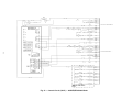
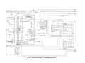
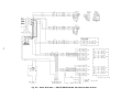
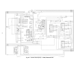
48/50EJ,EK,EW,EY024-068
50EJQ,EWQ024,028
Gas Heating/Electric Cooling
Electric Cooling and Heat Pump Units (50/60 Hz)
Wiring Diagrams
NOTE: This literature applies to units produced after 11/3/96
(software version 2.0 or greater)
DIAGRAM INDEX
UNIT LABEL DIAGRAM
Unit
Voltage
ALL
48EJ,EW024-034
208/230-3-60
460-3-60
575-3-60
ALL
48EK,EY024-034
208/230-3-60
460-3-60
575-3-60
ALL
50EJ,EW024-034
208/230-3-60
460-3-60
575-3-60
380-3-60
400-3-50
ALL
50EK,EY024-034
208/230-3-60
460-3-60
575-3-60
380-3-60
400-3-50
ALL
48EJ,EW038-048
208/230-3-60
460-3-60
575-3-60
ALL
48EJ,EY038-048
208/230-3-60
460-3-60
575-3-60
Label
Diagram Type
Component Arrangement
120-V Control Circuit
24-V Control Circuit
Power Schematic
Power Schematic
Power Schematic
Component Arrangement
120-V Control Circuit
24-V Control Circuit
Power Schematic
Power Schematic
Power Schematic
Component Arrangement
120-V Control Circuit
24-V Control Circuit
Power Schematic
Power Schematic
Power Schematic
Power Schematic
Power Schematic
Component Arrangement
120-V Control Circuit
24-V Control Circuit
Power Schematic
Power Schematic
Power Schematic
Power Schematic
Power Schematic
Component Arrangement
120-V Control Circuit
24-V Control Circuit
Power Schematic
Power Schematic
Power Schematic
Component Arrangement
120-V Control Circuit
24-V Control Circuit
Power Schematic
Power Schematic
Power Schematic
Serial
Number
Effective
3497F
1597F
3497F
2996F
2996F
2996F
3497F
1597F
2698F
2996F
2996F
2996F
3497F
1597F
1897F
2996F
2996F
2996F
2996F
2996F
3497F
1597F
2698F
2996F
2996F
2996F
2996F
2996F
1198F
1597F
3497F
1597F
1597F
2996F
1198F
1597F
2698F
1597F
1597F
2996F
Label
Diagram
Figure
No.
48EJ500730
48EJ501531
48EJ500387
48EJ500727
48EJ500727
48EJ500907
48EJ500730
48EJ501532
48EJ500729
48EJ500727
48EJ500727
48EJ500907
48EJ500730
48EJ501531
48EJ500900
48EJ500727
48EJ500727
48EJ500907
48EJ500908
48EJ500908
48EJ500730
48EJ501532
48EJ500901
48EJ500727
48EJ500727
48EJ500907
48EJ500908
48EJ500908
48EJ501527
48EJ501531
48EJ500387
48EJ501533
48EJ501533
48EJ500909
48EJ501527
48EJ501532
48EJ500729
48EJ501533
48EJ501533
48EJ500909
1
2
3
4
4
5
1
6
7
4
4
5
1
2
8
4
4
5
9
9
1
6
10
4
4
5
9
9
11
2
3
12
12
13
11
6
7
12
12
13
Manufacturer reserves the right to discontinue, or change at any time, specifications or designs without notice and without incurring obligations.
Book 1 1 1
PC 111
Catalog No. 564-826
Printed in U.S.A.
Form 48/50E-2W
Pg 1
9-98
Replaces: 48/50E-1W
Tab 1a 1b 5a
DIAGRAM INDEX (cont)
UNIT LABEL DIAGRAM
Unit
Voltage
ALL
50EJ,EW038-048
208/230-3-60
460-3-60
575-3-60
380-3-60
400-3-50
ALL
50EJ,EY038-048
20/230-3-60
460-3-60
575-3-60
380-3-60
400-3-50
ALL
48EJ,EW054-068
208/230-3-60
460-3-60
575-3-60
ALL
48EK,EY054-068
208/230-3-60
460-3-60
575-3-60
ALL
50EJ,EW054-068
208/230-3-60
460-3-60
575-3-60
380-3-60
400-3-50
ALL
50EK,EY054-068
208/230-3-60
460-3-60
575-3-60
380-3-60
400-3-50
ALL
50EJQ,EWQ024,028
208/230-3-60
460-3-60
Label
Diagram Type
Component Arrangement
120-V Control Circuit
24-V Control Circuit
Power Schematic
Power Schematic
Power Schematic
Power Schematic
Power Schematic
Component Arrangement
120-V Control Circuit
24-V Control Circuit
Power Schematic
Power Schematic
Power Schematic
Power Schematic
Power Schematic
Component Arrangement
120-V Control Circuit
24-V Control Circuit
Power Schematic
Power Schematic
Power Schematic
Component Arrangement
120-V Control Circuit
24-V Control Circuit
Power Schematic
Power Schematic
Power Schematic
Component Arrangement
120-V Control Circuit
24-V Control Circuit
Power Schematic
Power Schematic
Power Schematic
Power Schematic
Power Schematic
Component Arrangement
120-V Control Circuit
24-V Control Circuit
Power Schematic
Power Schematic
Power Schematic
Power Schematic
Power Schematic
Component Arrangement
120-V Control Circuit
24-V Control Circuit
Power Schematic
Power Schematic
2
Serial
Number
Effective
1198F
1597F
1897F
1597F
1597F
2996F
2996F
2996F
1198F
1597F
2698F
1597F
1597F
2996F
2996F
2996F
0898F
4297F
0898F
4297F
4297F
4297F
0898F
4297F
2698F
4297F
4297F
4297F
0898F
4297F
0898F
4297F
4297F
4297F
4297F
4297F
0898F
4297F
2698F
4297F
4297F
4297F
4297F
4297F
4297F
1597F
2997F
2996F
2996F
Label
Diagram
Figure
No.
48EJ501527
48EJ501531
48EJ500900
48EJ501533
48EJ501533
48EJ500909
48EJ600910
48EJ500910
48EJ501527
48EJ501532
48EJ500901
48EJ501533
48EJ501533
48EJ500909
48EJ500910
48EJ500910
48EJ501662
48EJ501669
48EJ501661
48EJ501659
48EJ500076
48EJ501663
48EJ501662
48EJ501664
48EJ501665
48EJ501659
48EJ500076
48EJ501663
48EJ501662
48EJ501669
48EJ501666
48EJ501659
48EJ500076
48EJ501663
48EJ501667
48EJ501667
48EJ501662
48EJ501664
48EJ501668
48EJ501659
48EJ500076
48EJ501663
48EJ501667
48EJ501667
48EJ500730
48EJ501531
48EJ501040
48EJ500727
48EJ500727
11
2
8
12
12
13
14
14
11
6
10
12
12
13
14
14
15
16
17
18
19
20
15
21
22
18
19
20
15
21
23
18
19
20
24
24
15
21
25
18
19
20
24
24
1
2
26
4
4
DIAGRAM INDEX (cont)
ACCESSORIES
Item
Power Exhaust (Constant Volume and Modulating)
Base Control Board
Expansion Board
Electric Heat
MotormasterT III Head Pressure Control Device
Remote Control Panel
Heat Interlock Relay
Field-Control Remote Start/Stop
Enthalpy Control
LID-2B Interface
Space Temperature Averaging
T-55 Space Temperature Sensor
T-56 Space Temperature Sensor
Service Tool Wiring
Supply-Air Temperature Reset
Smoke Detector
VFD Control
Figure No.
27,28*
29
30,31
32
33-37
38
39
40
41
42
43
44
45,46
47
48
49
50
*For 024-048 units power exhaust is shown in the unit wiring diagrams. Refer to the power and control wiring
diagrams for wiring information. For 054-068 units, the power exhaust is shown in Fig. 27 and 28.
expanded I/O points; perform Fire/Smoke control (power
exhaust required); if in Occupied mode, perform IAQ control and monitor the fan, filter, demand limit, and fieldapplied status (with accessories).
If thermostats are used to energize the G input, the control
module will turn on the indoor fan without delay and
open the economizer dampers to minimum position. If thermostats are used to deenergize the G input, the control module will turn off the indoor fan without delay and close the
economizer dampers.
When cooling, G must be energized before cooling can
operate. The control module determines if outdoor conditions are suitable for economizer cooling using the standard
outdoor air thermistor. For the economizer to function for
outside air cooling: the enthalpy must be below the enthalpy
set point; the outdoor-air temperature must be equal to or
less than the High Outdoor Air Temperature Lockout (default is 65 F); the SAT (supply-air temperature) thermistor must not be in alarm; and the outdoor air reading is
available. When these conditions are satisfied, the control
module will use economizer as the first stage of cooling.
When Y1 input is energized, the economizer will be modulated to maintain SAT at the defined set point. (The
default is 55 F.) When SAT is above the set point, the economizer will be 100% open. When SAT is below the set point,
the economizer will modulate between minimum and 100%
open position. When Y2 is energized, the control module
will turn on compressor no. 1 and continue to modulate the
economizer as described above. If the Y2 remains energized
and the SAT reading remains above the set point for 15 minutes, compressor no. 2 will turn on. If Y2 is deenergized at
any time, only the last stage of compression that was energized will be turned off. If outdoor conditions are not suitable for economizer cooling, the economizer will go to
minimum position and cycle compressors no. 1 and 2 based
on demand from Y1 and Y2 respectively. The compressors
will be locked out when the SAT temperature is too low (less
than 40 F for compressor no. 1 and less than 45 F for compressor no. 2). After a compressor is locked out, it can
restart after normal Time Guardt period.
The Time Guard function maintains a minimum off time
of 5 minutes, a minimum on time of 10 seconds, and a
minimum delay before starting the second compressor of
10 seconds.
48/50EJ,EK,EW,EY UNITS
NOTE: Unit is shipped with default values that can be changed
through CCN software or using an accessory LID-2B.
Cooling, Constant Volume (CV) Units — On power
up, the control module will activate the initialization software. The initialization software reads each DIP switch
to determine the unit configuration. The initialization
sequence: clears all alarms and alerts; re-maps the input/
output database for CV operation; sets maximum heat stages
to 2; and sets maximum cool stages to 3. The control module
reads DIP switch no. 3 and determines if the unit will use
expansion mode operation.
The TSTAT function performs a thermostat based control by monitoring Y1, Y2, W1, W2, and G inputs. These
functions control stages: cool1, cool2, heat1, heat2, and
the indoor fan, respectively. If the TSTAT function is not
selected, the control module determines the occupancy state
based on the system time schedules with a field-supplied sensor installed, or with remote occupied/unoccupied input. If
Temperature Compensated Start is active, the unit will be
controlled as in the Occupied mode.
Occupied or unoccupied comfort set points must be
selected. The control module will set appropriate operating
mode and fan control. The control module will turn on indoor fan if in Occupied mode or if the unit is in Unoccupied
mode and the space temperature is outside of the unoccupied comfort set points (Unoccupied Heat or Unoccupied Cool).
The control module will then monitor space temperature against
comfort set points and control heating or cooling stages as
required. If the system is in the Occupied mode, the economizer will operate as required. If the system is in Unoccupied mode, the system will perform nighttime free cool and
IAQ (indoor air quality) pre-occupancy purge as required
(when functions are enabled via software). Whenever the DX
(direct expansion) cooling is requested, the outdoor fan will
operate.
The control module will operate economizer, run diagnostics to monitor alarms/alerts at all times, and respond to
CCN communications to perform any configured network
POC (product outboard control) functions such as time/
outdoor-air temperature broadcast and global occupancy broadcast. When the optional expansion I/O board is employed,
it will: perform a periodic scan and maintain a database of
3
stage heat, both induced-draft motors operate, both gas valves
are energized, and both IGC boards initiate spark.
All of the gas heating control is performed through the
IGC boards (located in the heating section). The base module board serves only to initiate and terminate heating
operation.
The base module board is powered by 24 vac. When the
thermostat or room sensor calls for heating, power is sent
from the base module board to W on each of the IGC boards.
An LED on the IGC board will be on during normal operation. A check is made to ensure that the rollout switches
and limit switches are closed and the induced-draft motors
are not running. The induced-draft motors are then energized, and when speed is proven with the hall effect sensor
on the motor, the ignition activation period begins. The burners will ignite within 5 seconds.
When ignition occurs the IGC board will continue to monitor the condition of the rollout and limit switches, the hall
effect sensor, as well as the flame sensor. If the unit is
controlled through a room thermostat set for fan auto.,
45 seconds after ignition occurs, the indoor-fan motor will
be energized and the outdoor-air dampers will open to their
minimum position. If for some reason the overtemperature
limit opens prior to the start of the indoor fan blower, on the
next attempt, the 45-second delay will be shortened to 5 seconds less than the time from initiation of heat to when the
limit tripped. Gas will not be interrupted to the burners and
heating will continue. Once modified, the fan on delay will
not change back to 45 seconds unless power is reset to the
control. If the unit is controlled through a room sensor, the
indoor fan will be operating in the Occupied mode and the
outdoor-air dampers will be in the minimum position.
If the unit is controlled with a room sensor in the Unoccupied mode, the indoor fan will be energized through the
IGC board with a 45-second delay and the outside-air dampers will move to the IAQ (indoor air quality) position (generally closed in the Unoccupied mode). If IAQ is not enabled,
dampers will move to the minimum position.
When additional heat is required, W2 closes and initiates
power to the second stage of the main gas valves. When the
thermostat is satisfied, W1 and W2 open and the gas valves
close interrupting the flow of gas to the main burners. If the
call for W1 lasted less than 1 minute, the heating cycle will
not terminate until 1 minute after W1 became active. If the
unit is controlled through a room thermostat set for fan auto.,
the indoor-fan motor will continue to operate for an additional 45 seconds then stop and the outdoor-air dampers will
close. If the overtemperature limit opens after the indoor motor is stopped within 10 minutes of W1 becoming inactive,
on the next cycle the time will be extended by 15 seconds.
The maximum delay is 3 minutes. Once modified, the fan
off delay will not change back to 45 seconds unless power
is reset to the control. If the unit is controlled through a room
sensor, the indoor fan will be operating in the Occupied mode
and turned off after 45 seconds in the Unoccupied mode.
50 SERIES UNITS — The control module is powered by
24 vac. If the unit is controlled with a room sensor, the fan
will run continuously in the Occupied mode, with the outsideair damper in the minimum position. If the unit is controlled
through a room thermostat (with FAN set to AUTO), upon
a call for heat the first stage of heat is energized, the indoorfan motor will turn on, and the outdoor-air damper will move
to the minimum position. Upon a call for additional heat (if
the unit is equipped with a two-stage heater), the second stage
of heat is energized. When the call for heat is satisfied, the
heaters will deenergize. The indoor-fan motor will also deenergize (unless controlled by a room sensor) and the outdoorair damper will move to the closed position.
When heating, the heat stages respond to the demand from
W1 and W2 of the thermostat input. Heating and cooling will be mutually locked out on demand on a first call
basis. The heating and the cooling functions cannot operate
simultaneously.
Cooling, Variable Air Volume (VAV) Units — On
power up, the control module will activate the initialization
software. The initialization software reads each DIP switch
to determine the unit configuration. The initialization
sequence: clears all alarms and alerts; re-maps the input/
output database for VAV operation; sets maximum heat stages
to 1; and sets maximum cool stages to 6. The control module
reads DIP switch no. 3 and determines if the unit will use
expansion mode operation. Power up takes a random time of
1 to 63 seconds plus 5 minutes the first time power is sent
to the control board after a power outage.
The control module will determine if an interface (linkage) is active and if the unit will operate in a Digital Air
Volume (DAV) mode. In a DAV system, the room terminals
are equipped with microprocessor controls that give commands to the base unit module. If a linkage is active, the
control module will replace local comfort set points, space
and return air temperatures, and occupancy status with
the linkage data supplied.
The control module will determine occupancy status from
Time Schedules (if programmed), Remote Occupied/
Unoccupied input, global occupancy schedules, or DAV. If
temperature compensated start is active, the unit will be controlled as in the Occupied mode.
Temperature compensated start is a period of time calculated to bring the unit on while in Unoccupied mode to reach
the occupied set point when occupancy occurs.
The control module will set the appropriate operating mode
and fan control. The control module will turn on the variable
frequency drive (VFD) if Occupied mode is evident. If in
Unoccupied mode and a valid return-air temperature reading is available (either from a sensor or DAV), the control
module will monitor return-air temperature against unoccupied heat and cool set points. The control module will start
the VFD whenever return-air temperature is outside of the
set points (Unoccupied Heat or Unoccupied Cool). The VFD
may also be started by nighttime thermostat via remote
Occupied/Unoccupied input or by a temperature compensated start algorithm. When the VFD is running in a normal
mode, the control module will start heating or cooling as
required to maintain supply-air temperature at the supply air
set point plus the reset (when enabled). The reset value is
determined by SAT (supply-air temperature) reset and/or space
temperature reset algorithms. The space temperature reset
(requiring a space temperature sensor) is only available when
enabled through software.
When cooling, the control module will energize the power
exhaust enable output to the external power exhaust controller (when power exhaust is used).
The control module will run continuous diagnostics for
alarms/alerts; respond to CCN (Carrier Comfort Network)
communications; perform any configured network POC (Product Outboard Control) functions such as time/outdoor air temperature broadcast and global broadcast; and perform Fire/
Smoke control.
Heating, Constant Volume (CV) Units
48 SERIES UNITS — The gas heat units incorporate 2 separate systems to provide gas heat. Each system incorporates
its own induced-draft motor, Integrated Gas Control (IGC)
board, 2 stage gas valve, manifold, etc. The systems are operated in parallel; for example, when there is a call for first
4
IAQ (indoor air quality) unoccupied position (generally set
to zero in the Unoccupied mode). The duct pressure sensor
will signal to the variable frequency drive to operate at full
speed. When the call for heat is satisfied, the heaters will
deenergize.
NOTE: The HIR is not needed in a DAV system.
If the unit is in the Unoccupied mode, the indoor-fan motor will deenergize and the outdoor-air damper will move to
the closed position (if open).
If the unit is controlled with a room sensor the fan will not
run in the Unoccupied mode. Upon a call for heat, the first
stage of heat is energized, the indoor-fan motor will turn on,
and the outdoor air damper will move to the Unoccupied
IAQ (indoor air quality) position (generally set to zero in the
Unoccupied mode). The IAQ feature is enabled through system software. Upon a call for additional heat (if the unit is
equipped with a two-stage heater), the second stage of heat
is energized. When the call for heat is satisfied, the heaters
and indoor-fan motor will deenergize and the outdoor-air damper
will move to the closed position (if open).
Morning Warm-Up (VAV Only with PC Accessed/
CCN Operation) — Morning warm-up occurs when the
Heating, Variable Air Volume (VAV) Units
control module has been programmed to turn on heat, prior
to the Occupied mode, to be ready for the occupancy. Morning warm-up is a condition in VAV systems that occurs
when the Temperature Compensated Start algorithm calculates a biased occupied start time and the unit has a
demand for heating. The warm-up will continue into the
occupied period as long as there is a need for heat. During
warm-up, the unit can continue heating into the occupied
period, even if occupied heating is disabled. When the heating demand is satisfied, the warm-up condition will terminate. To increase or decrease the heating demand, use the
network access software to change the occupied heating set
point.
NOTE: To utilize morning warm-up mode, the unit occupancy schedule must be accessed via Service Tool,
ComfortWorks™, or Building Supervisor software or an
accessory LID-2B.
For current software (version 3.0 or later), the Low Temperature Minimum Damper Position Override (LOWMDP)
has a 0 to 100% limit, with a default of 100%. Think of the
LOWMDP as a second minimum damper position. This LOWMDP limit change requires access to the unit software with
a computer equipped with Building Supervisor, Service Tool,
or ComfortWorks™ Software.
When the LOWMDP is in effect the outdoor dampers will
remain at the LOWMDP position (typically set to 0% closed)
during heating, even in the Occupied period. For the
LOWMDP to be in effect the LOWMDP must be less than
the minimum damper position (MDP). For VAV applications the RAT (return-air temperature) must be less than the
OHSP (occupied heat set point) minus 2° F. Table 1 summarizes the operational requirements and controlling factors
for occupied heat and morning warm-up.
48 SERIES UNITS — All of the gas heating control is performed through the integrated gas control (IGC) board. The
base module board serves only to initiate and terminate heating operation.
NOTE: The unit is factory-configured for disabled occupied
heating. Dual In-line Package (DIP) switch 5 is used to
enable occupied heating (DIP switch 5 set to OPEN).
Variable Air Volume (VAV) occupied heat is controlled by
return-air temperature (RAT) using a 5k thermistor located
just below the outdoor air dampers. A VAV unit without a
space temperature sensor is also controlled by RAT. A VAV
unit with a space temperature sensor has unoccupied heat
controlled by space temperature (SPT).
The base module board is powered by 24 vac. When there
is a call for heating (either Morning Warm-Up, Unoccupied,
or Occupied modes), power is sent from the base module
board to W on each of the IGC boards and W2 of the main
gas valve. A field-supplied heat interlock relay signals for
the air terminals to open fully. The heat interlock relay is not
required on DAV systems. In the Occupied mode the indoorfan motor will be operating and the outdoor-air dampers will
be in the minimum position. In the Unoccupied mode the
indoor-fan motor will be off, but will energize 45 seconds
after the call for heat and the outdoor-air dampers will move
to the IAQ (indoor air quality) Unoccupied position (generally set to closed in the Unoccupied mode). The duct pressure sensor will signal to the variable frequency drive to
operate at full speed since all terminals have been driven
open. An LED on the IGC board will be on during normal
operation. A check is made to ensure that the rollout switches
and limit switches are closed and the induced-draft motors
are not running. The induced-draft motors are then energized and when speed is proven with the hall effect sensor
on the motor, the ignition activation period begins. The burners will ignite within 5 seconds.
When ignition occurs the IGC board will continue to monitor the condition of the rollout and limit switches, the hall
effect sensor, and the flame sensor.
If the call for heat lasted less than 1 minute, the heating
cycle will not terminate until 1 minute after heat became
active. When heating is satisfied, the power will be interrupted to the IGC board and W1 and W2 of the main gas
valve. If the unit is controlled through a room sensor, the
indoor fan will be operating in the Occupied mode and turned
off after 45 seconds in the Unoccupied mode.
50 SERIES UNITS — The control board is powered by
24 vac. When there is a call for heating (from Morning WarmUp, Unoccupied, or Occupied modes), power is sent from
the control module to energize the first stage of electric heat.
A field-supplied heat interlock relay signals for the air
terminals to fully open. In the Occupied mode, the indoorfan motor will operate continuously and the outdoor-air dampers will be in the minimum position. In the Unoccupied mode,
the indoor-fan motor will be off, but will energize upon the
call for heat. The outdoor-air dampers will move to the
Table 1 — Occupied Heat and Morning Warm-Up
Operation Requirements and Controlling Factors
SOFTWARE
VERSION
3.0 and 3.1
OCCUPIED
MORNING
TEMPERATURE
HEAT
WARM-UP
CONDITION
ENABLED
MAY START
FOR HEAT
VIA
DURING
TO START
DIP Switch
Smart start or
RAT < OHSP
no. 5
within 10 minutes
LEGEND
OHSP — Occupied Heat Set Point
RAT
— Return-Air Temperature
Morning Warm-Up (VAV Only with Stand-Alone
Operation) — When a unit operates in stand-alone mode,
morning warm-up occurs when the unit is energized in
Occupied mode and return-air temperature (RAT) is below
68 F. Warm-up will not terminate until the RAT reaches
68 F. The heat interlock relay output is energized during morning warm-up. (A field-installed 24-vac heat interlock relay is
required.) The output will be energized until the morning
warm-up cycle is complete.
5
Table 2 — VFD Supply-Air Pressure Set Point
Space Temperature Reset Sensor (VAV Only)
— An accessory space temperature sensor (T-55 or T-56 with-
PRESSURE
in. wg
kPa
0.00
0.000
0.25
0.062
0.50
0.124
0.75
0.187
1.00
0.249
1.25
0.311
1.50
0.373
1.75
0.435
2.00
0.498
2.25
0.560
2.50
0.622
2.75
0.684
3.00
0.747
3.25
0.809
3.50
0.871
out offset) is required. Space temperature reset is used to
reset the supply-air temperature set point of a VAV system
higher, as the space temperature falls below the Occupied
Cool set point. As the space temperature falls below the cool
set point, the supply-air temperature will be reset upward
as a function of the reset ratio. Reset ratio is expressed in
degrees change in supply-air temperature per degree of space
temperature change. A reset limit will exist which will limit
the maximum number of degrees the supply-air temperature
may be raised. Both the reset ratio and the reset limit are
user definable. The sequence of operation is as follows:
1. The on/off status of the unit supply fan is determined.
2. If the fan is on, the sequence will check if the system is
in Occupied mode.
3. If the system is in Occupied mode, the sequence will
determine if the reset option is enabled.
4. If the reset option is enabled, the sequence will read the
space temperature and compare it to the Occupied Cool
set point. If the temperature is below the Occupied Cool
set point, the algorithm will compute the reset value and
compare this value against the reset limit. If it is greater
than the reset limit, the sequence will use the reset limit
as the reset value.
NOTE: A computer equipped with Carrier network access
software (ComfortWorks™, Building Supervisor, or Service
Tool) or an accessory LID-2B is required to enable this
function.
CONTROL
(mA)
VFD
SET POINT
4.0
4.8
5.6
6.4
7.2
8.0
8.8
9.6
10.4
11.2
12.0
12.8
13.6
14.4
15.2
0
3
6
9
12
15
18
21
24
27
30
33
36
39
42
LEGEND
VFD — Variable Frequency Drive
50EJQ,EWQ UNITS
NOTE: Unit is shipped with default values that can be changed
through Service Tool or CCN software.
Cooling — On power up, the control module will activate the initialization software. The initialization software
reads DIP switch no. 1 position to determine CV operation.
Next, DIP switch no. 2 is read to determine if the control is
TSTAT or sensor type operation. The initialization
sequence: clears all alarms and alerts; re-maps the input/
output database for CV operation; sets maximum heat stages
to 2; and sets maximum cool stages to 3. The control module
reads DIP switch no. 3 and determines if the unit will use
expansion mode operation.
The TSTAT function performs a thermostat based control
by monitoring Y1, Y2, W1, W2 and G inputs. These functions control stages: cool1, cool2, heat1, heat2, and the
indoor fan respectively. If the TSTAT function is not
selected, the control module determines the occupancy state
based on the system time schedules or with remote occupied/
unoccupied input. If Temperature Compensated Start is
active, the unit will be controlled as in the Occupied mode.
Occupied or unoccupied comfort set points must be
selected. Use of the space temperature offset input can also
be configured. The control module will set appropriate operating mode and fan control. The control module will turn
on indoor fan if in Occupied mode or if the unit is in Unoccupied mode and the space temperature is outside of the
unoccupied comfort set points (Unoccupied Heat or Unoccupied Cool). The control module will then monitor space
temperature against comfort set points and control heating
or cooling stages as required. If the system is in the Occupied mode, the economizer will operate as required. If the
system is in Unoccupied mode, the system will perform nighttime free cool and IAQ (indoor air quality) pre-occupancy
purge as required (when functions are enabled via software).
Whenever the DX (direct expansion) cooling is requested,
the outdoor fan will operate.
Supply-Air Temperature Reset (VAV Only) — A
field-supplied 4 to 20 mA input signal enables the supply-air
temperature to be reset 0° to 20° F (0° or 11.2° C). The supplyair temperature reset option does not need to be enabled.
VFD Control Via Field-Supplied 4 to 20 mA (Third
Party Transducer) — To set the VFD for field-supplied
4 to 20 mA, the VFD must be powered up; however, since
it is located near the indoor air fan, operation of the fan is
not desirable. To disable the fan perform the following
procedure:
1. Open the indoor fan circuit breaker.
2. Remove the jumper between CC and ST on the terminal
strip of the VFD (see Fig. 50).
3. Move the jumper between CC and SS1 to CC and SS2
(JOG) on the terminal strip of the VFD.
4. Close the indoor fan circuit breaker. The VFD is powered, but the fan will not operate.
5. On the front of the VFD is a keypad and display which
will be used to turn off the PID. To access this field, press
the PRG key until the display reads J.PrG (Jump Frequency Group Parameters). Press the ARROW key until
Fb.PI (Item 7, PID Set Point Control Select) is displayed.
Use the UP or DOWN arrow key to adjust the setting to
0. The default value is 0. See Table 2.
6. Open the indoor fan circuit breaker.
7. Replace the jumper between CC and ST on the terminal
strip of the VFD.
8. Close the indoor fan circuit breaker. The VFD is now powered and the fan will operate.
6
heat is energized, energizing heat relay (HR2) and reversing valve solenoids (RVS1 and 2). Compressor no. 1 and 2,
indoor and outdoor-fan motors start, and the outdoor-air damper
will move to the Unoccupied IAQ position (generally set to
zero in the Unoccupied mode). The IAQ feature is enabled
through system software. Upon a call for additional heat (if
equipped with electric heaters), the second stage of heat is
energized. When the call for heat is satisfied, the compressors, fan motors, and heaters will be deenergized and the
outdoor-air damper will move to the closed position.
The control module will operate economizer, run diagnostics to monitor alarms/alerts at all times, and respond to
CCN communications to perform any configured network
POC (product outboard control) functions such as time/
outdoor-air temperature broadcast and global occupancy broadcast. When the optional expansion I/O board is employed,
it will: perform a periodic scan and maintain a database of
expanded I/O points; perform Fire/Smoke control (power exhaust required); if in Occupied mode, perform IAQ control
and monitor the fan, filter, demand limit, and field-applied
status (with accessories).
If thermostats are used to energize the G input, the control
module will turn on the indoor fan without delay and open
the economizer dampers to minimum position. If thermostats are used to deenergize the G input, the control module
will turn off the indoor fan without delay and close the economizer dampers.
When cooling, G must be energized before cooling can
operate. The control module determines if outdoor conditions are suitable for economizer cooling using the standard
outdoor air thermistor. For the economizer to function for
outside air cooling: the enthalpy must be below the enthalpy
set point; the outdoor-air temperature must be equal to
or less than the High Outdoor Air Temperature Lockout
(default is 65 F); the SAT (supply-air temperature) thermistor must not be in alarm; and the outdoor air reading is
available. When these conditions are satisfied, the control
module will use economizer as the first stage of cooling.
When Y1 input is energized, the economizer will be modulated to maintain SAT at the defined set point. (The default
is 55 F.) When SAT is above the set point, the economizer
will be 100% open. When SAT is below the set point, the
economizer will modulate between minimum and 100% open
position. When Y2 is energized, the control module will turn
on compressor 1 and continue to modulate the economizer
as described above. If the Y2 remains energized and the SAT
reading remains above the set point for 15 minutes, compressor 2 will turn on. If Y2 is deenergized at any time, only
the last stage of compression that was energized will be turned
off. If outdoor conditions are not suitable for economizer cooling, the economizer will go to minimum position and cycle
compressors 1 and 2 based on demand from Y1 and Y2
respectively. The compressors will be locked out when the
SAT temperature is too low (less than 40 F for compressor
1 and less than 45 F for compressor 2). After a compressor
is locked out, it can restart after normal Time Guardt
period.
The Time Guard function maintains a minimum off time
of 5 minutes, a minimum on time of 10 seconds, and a
minimum delay before starting the second compressor of
10 seconds.
Defrost Cycle — When the temperature of the outdoor
coil drops below 28 F as sensed by the defrost thermostat
(DFT1 or 2) and the defrost timer is at the end of a timed
period (adjustable at 30 to 90 minutes) the defrost cycle will
begin. The control board will deenergize the reversing valve
solenoids (RVS1 and 2) and energize the electric heat. Also,
the outdoor-fan motor will stop.
The unit will continue to defrost until the coil temperature
as measured by DFT1 and 2 reaches 65 F or the duration of
defrost cycle completes a 10-minute period.
During the defrost mode, if a circuit defrosts first, the RVS
will oscillate between heating and cooling modes until defrost mode is complete. This will keep the head pressure on
that circuit from getting too high.
At the end of the defrost cycle, the electric heaters will be
deenergized, reversing valve solenoids will be energized, and
the outdoor fan will start.
POWER EXHAUST OPERATION
Power exhaust has two options (Constant Volume and Modulating) that have the following sequence of operation:
The first stage of constant volume (CV) power exhaust is
enabled when the indoor fan has been energized and the
desired damper position for the economizer increases above
the CV power exhaust set point (PES1). The default for PES1
is set at 25%. The second stage of power exhaust is enabled
when the desired damper position for the economizer
increases above the second CV power exhaust set point (PES2).
The default for PES2 is set at 75%. Each stage is disabled
when the desired damper position decreases below the
respective set points.
The modulating power exhaust is enabled when the indoor fan is energized and the building pressure has exceeded
the individual sequencer set points. The default set points
are 0.04 in. wg (9.9 Pa) (6.3 vdc) for stage 1, 0.10 in. wg
(24.9 Pa) (6.8 vdc) for stage 2, 0.16 in. wg (39.8 Pa)
(7.3 vdc) for stage 3, 0.23 in. wg (57.1 Pa) (7.8 vdc) for
stage 4, 0.29 in. wg (72.0 Pa) (8.3 vdc) for stage 5, and
0.35 in. wg (86.9 Pa) (8.8 vdc) for stage 6 power exhaust
sequencer. Each stage also requires that the building pressure is reduced until it drops below the disable set point. The
default set points are 0 in. wg (0 Pa) (6.0 vdc) for stage 1,
0.060 in. wg (14.9 Pa) (6.5 vdc) for stage 2, 0.13 in. wg
(32.3 Pa) (7.0 vdc) for stage 3, 0.19 in. wg (47.2 Pa)
(7.4 vdc) for stage 4, 0.25 in. wg (47.5 Pa) (8.0 vdc) for
stage 5, and 0.31 in. wg (62.4 Pa) (8.5 vdc) for stage 6 power
exhaust sequencer. Both of these set points are changed at
the specific controlling sequencer.
Heating — The control module is powered by 24 vac. If
the unit is controlled with a room sensor, the fan will run
continuously in the Occupied mode, with the outside-air damper
in the minimum position. If the unit is controlled through a
room thermostat (with FAN set to AUTO), upon a call for
heat the first stage heat is energized, energizing heat relay
(HR2) and reversing valve solenoids (RVS1 and 2). Compressor no. 1 and 2, indoor and outdoor-fan motors start. Upon
a call for additional heat (if equipped with electric heaters),
the second stage of heat is energized. When the call for heat
is satisfied, the compressors, fan motors, and heaters will be
deenergized and the outdoor-air damper will move to the closed
position.
If the unit is controlled with a room sensor the fan will not
run in the Unoccupied mode unless the space temperature is
below the unoccupied heat set point or above the unoccupied cool set point. Upon a call for heat, the first stage of
SMOKE CONTROL MODES
The 48/50EJ,EK,EW,EY and 50EJQ,EWQ units with an
optional expansion board perform fire and smoke control modes.
The expansion board provides 4 modes which can be used
to control smoke within the conditioned area. The modes of
operation are fire shutdown, pressurization, evacuation, and
smoke purge. See Table 3.
7
which may be changed through network access software. To
work properly, the IAQ sensor high and low reference points
for the sensor that is used must match the configured values.
The expansion board reacts to a 4 to 20 mA signal from the
IAQ sensor. The low reference (4 mA output) must be configured to the minimum IAQ sensor reading. The high reference (20 mA output) must be configured to the maximum
IAQ sensor reading.
The IAQ sensor can be configured to either low or high
priority. The priority value can be changed by the user. The
default is low.
SMOKE DETECTOR
A smoke detector can be used to initiate fire shutdown.
This can be accomplished by a set of normally closed pilot
relay contacts which will interrupt power from the 24-v transformer, secondary ‘‘B’’ terminal to the control circuit breaker
(CB4). The wire that connects these two points is white and
labeled ‘‘W78.’’
NOTE: On standard gas models, the indoor fan will continue to run 45 seconds after the call for heat has been
terminated. If fire shutdown is initiated the fan will stop
immediately. No 45-second delay will occur.
The smoke detector may be mounted in the return-air
duct or the supply duct. Carrier does not make recommendations as to specific smoke detector location due to liability
considerations.
Low Priority — When the priority is set to low, the initial control is to the IAQ set point, but the outside air damper
position will change to its minimum position when the following conditions occur:
• CV units with sensor — when the space temperature is
greater than the occupied cooling set point plus 2° F or
when the space temperature is less than the occupied heating set point minus 2° F.
• VAV units and CV units with thermostat — when the
supply-air temperature is less than the supply-air temperature set point minus 8° F or when the supply-air temperature is greater than the supply air temperature set point
plus 5° F for 4 minutes.
• When the outdoor air quality is greater than the outdoor
air quality set point (ppm)
IAQ CONTROL
The accessory expansion board and accessory IAQ (indoor air quality) sensor are required for IAQ control. The
Carrier sensors operate with a 4 to 20 mA signal. The 4 to
20 mA signal is connected to T11 (+) and T12 (−) on the
expansion board for the IAQ sensor, and T13 (+) and T14
(−) on the expansion board for the OAQ (outdoor air quality) sensor. The sensor is field-mounted and wired to the
expansion board installed in the unit main control box. The
IAQ sensor must be powered by a field-supplied 24-v power
supply (ungrounded). Do not use the unit 24-v power supply
to power the sensor.
Once installed, the sensor must be enabled via unit software access. The sensor is configured with default values
High Priority — When the priority is set to high, the IAQ
set point controls the outside air damper exclusively, with
no regard to comfort conditioning.
Table 3 — Smoke Control Modes
DEVICE
Economizer
Indoor Fan/VFD
Power Exhaust (all outputs)
Heat Stages
HIR
PRESSURIZATION
100%
ON
OFF
OFF
ON
SMOKE PURGE
100%
ON
ON
OFF
ON
LEGEND
HIR — Heat Interlock Relay
VFD — Variable Frequency Drive
8
EVACUATION
100%
OFF
ON
OFF
OFF
FIRE SHUTDOWN
0%
OFF
OFF
OFF
OFF
I/O CHANNEL DESIGNATIONS BASE MODULE — CV
TERMINAL NO.
T1-2
T3-4
T5-6
T7-8
T9-10
T11-12
T13-14
T15-16
T17-25
T18-25
T19-25
T20-25
T21-25
T22-25
ASSIGNMENT
TERMINAL NO.
SPT (CCN) — 10KV Thermistor
T23-25
STO (CCN) — 10KV Thermistor
T24-25
OAT — 5KV Thermistor
T26-27
SAT — 5KV Thermistor
T28-29
—
T30-29
SAT Reset — AI (4 to 20 mA)
T31-32
—
T33-32
—
T34-35
Y1 or Remote Start/Stop — DI (24 vac)
T36-35
Y2 — DI (24 vac)
T37-38
W1 — DI (24 vac)
T39-38
W2 — DI (24 vac)
K1
G — DI (24 vac)
K2
Compressor 1 Safety — DI (24 vac)
K3
ASSIGNMENT
Compressor 2 Safety — DI (24 vac)
Outside Air Enthalpy — DI (24 vac)
Economizer Pos. — AO (4-20 mA)
Heat 1 Relay — DO (24 vac)
Heat 2 Relay — DO (24 vac)
CV Power Exhaust 1/Modulating Power Exhaust — DO (115 vac)
CV Power Exhaust 2 — DO (115 vac)
Condenser Fan — DO (115 vac)
OFC2 — DO (115 vac)
—
—
Indoor Fan Relay — DO (LV)
Compr. 1 — DO (HV)
Compr. 2 — DO (HV)
I/O CHANNEL DESIGNATIONS BASE MODULE — VAV
TERMINAL NO.
T1-2
T3-4
T5-6
T7-8
T9-10
T11-12
T13-14
T15-16
T17-25
T18-25
T19-25
T20-25
T21-25
T22-25
ASSIGNMENT
SPT (CCN) — 10KV Thermistor
RAT — 5KV Thermistor
OAT — 5KV Thermistor
SAT — 5KV Thermistor
—
SAT Reset — AI (4 to 20 mA)
—
—
Remote Start/Stop — DI (24 vac)
—
—
—
—
Compressor 1 Safety — DI (24 vac)
TERMINAL NO.
T23-25
T24-25
T26-27
T28-29
T30-29
T31-32
T33-32
T34-35
T36-35
T37-38
T39-38
K1
K2
K3
ASSIGNMENT
Compressor 2 Safety — DI (24 vac)
Outside Air Enthalpy — DI (24 vac)
Economizer Pos. — AO (4-20 mA)
Heat 1 Relay − DO (24 v)
Heat Interlock Relay — DO (24 v)
Modulated Power Exhaust — DO (24 vac)
—
Condenser Fan — DO (115 vac)
OFC2 — DO (115 vac)
Unloader 1 — DO (115 vac)
Unloader 2 — DO (115 vac)
Indoor Fan Relay — DO (LV)
Compr. 1 — DO (HV)
Compr. 2 — DO (HV)
I/O CHANNEL DESIGNATIONS EXPANSION MODULE (Field-Installed) — CV AND VAV
TERMINAL NO.
T1-2
T3-4
T5-6
T7-8
T9-10
T11-12
T13-14
T15-16
T17 and TB2-1
T18 and TB2-1
T19 and TB2-1
T20 and TB2-1
T21 and TB2-1
T22 and TB2-1
AI
AO
CCN
CV
DI
DO
HV
IAQ
KV
LV
—
—
—
—
—
—
—
—
—
—
ASSIGNMENT
—
—
—
—
—
IAQ Indoor — AI (4 to 20 mA)
IAQ Outdoor — AI (4 to 20 mA)
—
Fan Status — DI (24 vac)
Filter Status − DI (24 vac)
Field Applied Status — DI (24 vac)
Demand Limit — DI (24 vac)
Fire — Unit Shutdown — DI (24 vac)
Fire — Pressurization — DI (24 vac)
LEGEND
Analog Input
OAT
Analog Output
OFC
Carrier Comfort Network
RAT
Constant Volume
SAT
Direct Input
SPT
Direct Output
STO
High Voltage
T
Indoor Air Quality
TB
Kilo-Ohms
VAV
Low Voltage
—
—
—
—
—
—
—
—
—
TERMINAL NO.
T23 and TB2-1
T24 and TB2-1
T26-27
T28-29
T30 and TB2-2
T31
T33
T34
T36
T37
T39
K1
K2
K3
Outdoor-Air Temperature
Outdoor Fan Contactor
Return-Air Temperature
Supply-Air Temperature
Space Temperature
Space Temperature Offset
Terminal
Terminal Block
Variable Air Volume
9
ASSIGNMENT
Fire — Evacuation — DI (24 vac)
Fire — Smoke Purge — DI (24 vac)
—
—
Alarm Light Indicator — DO (24 vac)
Power Exhaust Fire No. 1 — DO (115
Power Exhaust Fire No. 2 — DO (115
Power Exhaust Fire No. 3 — DO (115
Power Exhaust Fire No. 4 — DO (115
Modulating Power Exhaust No. 5
Modulating Power Exhaust No. 6
—
—
—
vac)
vac)
vac)
vac)
NOTE: All even numbered terminals are negative (−) polarity
and all odd numbered terminals are positive (+) polarity.
LEGEND
AHA
BP
BPS
BR
C
CAP
CB
CC
CCB
CCH
CCN
CLG
COM
COMP
COMPR
CR
CV
D
DFT
DIP
DM
DP
EC
EQUIP
FLA
FPT
FU
GND
GRD
GVR
HC
HIR
HPS
—
—
—
—
—
—
—
—
—
—
—
—
—
—
—
—
—
—
—
—
—
—
—
—
—
—
—
—
—
—
—
—
—
Adjustable Heat Anticipator
Building Pressure
Bypass Switch
Burner Relay
Contactor, Compressor
Capacitor
Circuit Breaker
Cooling Compensator
Control Circuit Breaker
Crankcase Heater
Carrier Comfort Network
Cooling
Communication
Compressor Motor
Compressor Motor
Control Relay
Constant Volume
Diode
Defrost Thermostat
Dual In-Line Package
Damper Motor
Duct Pressure
Enthalpy Control
Equipment
Full Load Amps
Freeze Protection Thermostat
Fuse
Ground
Ground
Gas Valve Relay
Heater Contactor
Heat Interlock Relay
High-Pressure Switch
HR
HS
HTG
I
IAQ
IDM
IFC
IFCB
IFM
IFR
IGC
—
—
—
—
—
—
—
—
—
—
—
INC
IP
L
LED
LPS
LS
MGV
MMSN
NC
NEC
NO
OAQ
OAT
OCC
OD
OFC
OFM
PEC
PEM
PES
—
—
—
—
—
—
—
—
—
—
—
—
—
—
—
—
—
—
—
—
Heater Relay
Hall Effect Sensor
Heating
Ignitor
Indoor Air Quality
Induced-Draft Motor
Indoor-Fan Contactor
Indoor Fan Circuit Breaker
Indoor-Fan Motor
Indoor-Fan Relay
Intergrated Gas Unit
Controller
Increasing
Internal Protector
Light
Light-Emitting Diode
Low-Pressure Switch
Limit Switch
Main Gas Valve
Motormaster
Normally Closed
National Electrical Code
Normally Open
Outdoor Air Quality
Outdoor-Air Thermostat
Occupied
Outside Diameter
Outdoor-Fan Contactor
Outdoor-Fan Motor
Power Exhaust Contactor
Power Exhaust Motor
Power Exhaust Sequencer
NOTE FOR FIG. 3, 7, 8, 10, 17, 22, 23,
25, AND 26
PESC
— Power Exhaust Sequencer
Controller
PL
— Plug Assembly
R
— Relay
RAT
— Return-Air Thermistor
RS
— Rollout Switch
RVS
— Reversing Valve Solenoid
SAT
— Supply-Air Thermistor
SIO
— Serial Input/Output
SPT
— Space Temperature Sensor
SW
— Switch
T
— Terminal
TB
— Terminal Block
TC
— Thermostat Cooling
TH
— Thermostat Heating
TRAN
— Transformer
UNOCC — Unoccupied
UL
— Compressor Unloader
VAV
— Variable Air Volume
VFD
— Variable Frequency Drive
Terminal (Marked)
Terminal (Unmarked)
Terminal Block
Splice
Factory Wiring
Field Wiring
To indicate common potential
only, not to represent wiring
NOTES FOR FIG. 9 AND 14
1. Connect TRAN1 to H3 for 380-v and 400-v units.
2. Connect TRAN2 to orange lead for 380-v and 400-v units.
3. Circuit breaker Must Trip Amps are equal to or less than 156%
FLA for CB1 and CB2. All others are 140%.
4. If any of the original wire furnished must be replaced, it must be
replaced wit type 90 C wire or its equivalent.
5. Compressors and/or fan motors are thermally protected.
6. Three-phase motors are protected against primary single phasing
conditions.
1. The red and violet wires are spliced together at the factory. The
brown wire has a wire nut added at the factory.
NOTES FOR FIG. 4 AND 12
1. Connect TRAN1 to H4 for 460-v units. Connect to H3 for 230-v. If
208/230-v units are run with a 208-v power supply, connect to H2.
2. Connect TRAN2 to black lead for 460-v units. Connect to orange
lead for 230-v units. If 208/230-v units are run with a 208-v power
supply, connect to red lead.
3. Circuit breaker Must Trip Amps are equal to or less than 156%
FLA for CB1 and CB2. All others are 140%.
4. If any of the original wire furnished must be replaced, it must be
replaced with type 90 C wire or its equivalent.
5. Compressors and/or fan motors are thermally protected.
6. Three-phase motors are protected against primary single phasing
conditions.
NOTES FOR FIG. 18
1. If 208/230-v units are run with a 208-v power supply, connect
to H2.
2. If 208/230-v units are run with a 208-v power supply, connect to
red lead.
3. Circuit breaker Must Trip Amps are equal to or less than 156%
FLA for CB1 and CB2. All others are 140%.
4. If any of the original wire furnished must be replaced, it must be
replaced with type 90 C wire or its equivalent.
5. Fan motors are thermally protected.
6. Three-phase motors are protected against primary single phasing
conditions.
NOTES FOR FIG. 5 AND 13
1. Connect TRAN1 to H4 for 575-v units.
2. Connect TRAN2 to black lead for 575-v units.
3. Circuit breaker Must Trip Amps are equal to or less than 156%
FLA for CB1 and CB2. All others are 140%.
4. If any of the original wire furnished must be replaced, it must be
replaced with type 90 C wire or its equivalent.
5. Compressors and/or fan motors are thermally protected.
6. Three-phase motors are protected against primary single phasing
conditions.
NOTES FOR FIG. 19, 20, AND 24
1. Circuit breaker Must Trip Amps are equal to or less than 156%
FLA for CB1 and CB2. All others are 140%.
2. If any of the original wire furnished must be replaced, it must be
replaced with type 90 C wire or its equivalent.
3. Fan motors are thermally protected.
4. Three-phase motors are protected against primary single phasing
conditions.
10
FACTORY SETTINGS OF
MODULATING POWER EXHAUST SEQUENCERS
OFF
ON
OFF
ON
Offset DIFF
Voltage Voltage Static Static
Stage 1
50%
3%
6.0
6.3
0.00
0.04
(PES1)
Stage 2
55%
3%
6.5
6.8
0.06
0.10
(PES2)
Stage 3
60%
3%
7.0
7.3
0.12
0.16
(PES3)
Stage 4
64%
3%
7.4
7.7
0.18
0.22
(PES4)
11
ERROR CODE DESCRIPTION
FOR CONTROL BOARD
LED
Blinks
2
3
4
5
6
7
8
9
10
11
Error Mode
Compressor 1 Safety
Compressor 2 Safety
Thermostat Failure
SAT Thermistor Failure
OAT Thermistor Failure
SPT Thermistor Failure
RAT Thermistor Failure
Loss of Communications with Expansion Board
Control Board Failure
Expansion I/O Board Failure
ERROR CODE DESCRIPTION
FOR IGC CONTROL BOARD
LED
Blinks
ON
OFF
1
2
3
4
5
6
7
8
Error Mode
Normal Operation
Hardware Failure
Fan On/Off Delay Modified
Limit Switch Fault
Flame Sense Fault
Four Consecutive Limit Switch Faults
Ignition Lockout Fault
Induced Draft Motor Fault
Rollout Switch Fault
Internal Control Fault
NOTE: When W1 is energized the burners will remain
on for a minimum of 60 seconds. If more than one error
mode exists they will be displayed on the LED in
sequence.
Setting
1
Open
VAV
Closed
CV
BASE MODULE CONTROL BOARD DIP SWITCH ASSIGNMENTS
2
3
4
5
6
VAV
VAV
Time GuardT
Space Sensor
Occupied Heat
Override On
Installed
Enabled
Expansion Field
In Conjunction
I/O
Test
CV,
CV
with Field Test
Board
On
CCN or
Modulated
Set Minimum
Sensors
Power Exhaust
Damper Position
Used
On
VAV
VAV
No Space
Occupied Heat
Base
Field
Sensor
Disabled
Control
Time Guard
Test
Board
Override Off
CV
Off
CV
Only
Constant Volume
Thermostat
Power Exhaust
7
8
Gas
Heat
Heat
Pump
Electric
Heat
Standard
A/C
Operation
Fig. 1 — Component Arrangement — 48/50EJ,EK,EW,EY024-034 and 50EJQ,EWQ024,028 Units
VFD SET POINTS FOR
SUPPLY AIR PRESSURE
Pressure
Control
VFD
in. wg
Output mA
Set Point
0.00
4.00
0.0
0.25
4.80
3.0
0.50
5.60
6.0
0.75
6.40
9.0
1.00
7.20
12.0
1.25
8.00
15.0
1.50
8.80
18.0
1.75
9.60
21.0
2.00
10.40
24.0
2.25
11.20
27.0
2.50
12.00
30.0
2.75
12.80
33.0
3.00
13.60
36.0
3.25
14.40
39.0
3.50
15.20
42.0
12
Fig. 2 — Control Circuit (120-V) — 48/50EJ,EW024-048 and 50EJQ,EWQ024,028 Units
13
Fig. 3 — Control Circuit (24-V) — 48EJ,EW024-048 Units
14
TABLE A
The Following Compressors Have
Two Parallel Wires Run from TB1
to the Compressors
Compressor
Wire
Voltage
Model
Quantity
06D-537
208/230-3-60
2
TABLE B
The Following Fan Motors Have
Two Parallel Wires Run from TB1
to the Fan Motors
Indoor
Wire
Voltage
Motor
Quantity
20 Hp
208/230-3-60
2
Fig. 4 — Power Schematic — 48/50EJ,EK,EW,EY024-034 and 50EJQ,EWQ024,028; 208/230-3-60 and 460-3-60 Units
15
Fig. 5 — Power Schematic — 48/50EJ,EK,EW,EY024-034; 575-3-60 Units
16
Fig. 6 — Control Circuit (120-V) — 48/50EK,EY024-048 Units
17
TABLE A
For Software
Version 1.0 Connect
Between R and Y1
For Software
Version 2.0 Connect
Between R and W1
Fig. 7 — Control Circuit (24-V) — 48EK,EY024-048 Units
18
TABLE A
For Software Version 1.0
Connect Between R and Y1
For Software Version 2.0
Connect Between R and W1
Fig. 8 — Control Circuit (24-V) — 50EJ,EW024-048 Units
19
Fig. 9 — Power Schematic — 50EJ,EK,EW,EY024-034; 380-3-60 and 400-3-50 Units
20
TABLE A
For Software Version 1.0
Connect Between R and Y1
For Software Version 2.0
Connect Between R and W1
Fig. 10 — Control Circuit (24-V) — 50EK,EY024-048 Units
VFD SET POINTS FOR
SUPPLY AIR PRESSURE
Pressure
Control
VFD
in. wg
Output mA
Set Point
0.00
4.00
0.0
0.25
4.80
3.0
0.50
5.60
6.0
0.75
6.40
9.0
1.00
7.20
12.0
1.25
8.00
15.0
1.50
8.80
18.0
1.75
9.60
21.0
2.00
10.40
24.0
2.25
11.20
27.0
2.50
12.00
30.0
2.75
12.80
33.0
3.00
13.60
36.0
3.25
14.40
39.0
3.50
15.20
42.0
21
BASE MODULE CONTROL BOARD DIP SWITCH ASSIGNMENTS (VERSION 1.0 SOFTWARE)
Setting
1
2
3
4
5
6
7
8
Time GuardT
Expansion
Field
Modulated
Override
On
Factory
CCN/
Gas
Open
VAV
I/O
Test
Power
Set Minimum
Test
Sensors
Heat
Board
On
Exhaust
Damper Position
On
On
Time Guard
Base
Field
CV
Override Off
Electric Factory
Closed
CV
Thermostat
Board
Test
Power
Set Minimum
Test
Heat
Only
Off
Exhaust
Damper Position
Off
Off
ERROR CODE DESCRIPTION FOR CONTROL BOARD
LED Blinks
Error Mode
2
Compressor 1 Safety
3
Compressor 2 Safety
4
Thermostat Failure
5
SAT Thermistor Failure
6
OAT Thermistor Failure
7
SPT Thermistor Failure
8
RAT Thermistor Failure
9
Loss of Communications with Expansion Board
10
Control Board Failure
11
Expansion I/O Board Failure
NOTE: When W1 is energized the burners will remain on
for a minimum of 60 seconds. If more than one error mode
exists they will be displayed on the LED in sequence.
BASE MODULE CONTROL BOARD DIP SWITCH ASSIGNMENTS (VERSION 2.0 SOFTWARE)
1
2
3
4
5
6
7
8
VAV
VAV
Time Guard
Space Sensor
Occupied Heat
Override On
Installed
Enabled
Expansion Field
Heat
Gas
In Conjunction
Open
VAV
I/O
Test
Pump
CV,
Heat
CV
with Field Test
Board
On
Operation
CCN or
Modulated
Set
Minimum
Sensors
Power Exhaust
Damper Position
Used
On
Setting
Closed
CV
VAV
No Space
Sensor
CV
Thermostat
Base
Control
Board
Only
Field
Test
Off
VAV
Occupied Heat
Disabled
CV
Constant Volume
Power Exhaust
ERROR CODE DESCRIPTION FOR IGC
CONTROL BOARD
Error Mode
Normal Operation
Hardware Failure
Fan On/Off Delay Modified
Limit Switch Fault
Flame Sense Fault
Four Consecutive Limit Switch Faults
Ignition Lockout Fault
Induced Draft Motor Fault
Rollout Switch Fault
Internal Control Fault
LED Blinks
ON
OFF
1
2
3
4
5
6
7
8
Time Guard
Override Off
Electric
Heat
Fig. 11 — Component Arrangement — 48/50EJ,EK,EW,EY038-048
Standard
A/C
Operation
FACTORY SETTINGS OF
MODULATING POWER EXHAUST SEQUENCERS
OFF
ON
OFF
ON
Offset DIFF
Voltage Voltage Static Static
Stage 1
50%
3%
6.0
6.3
0.00
0.04
(PES1)
Stage 2
55%
3%
6.5
6.8
0.06
0.10
(PES2)
Stage 3
60%
3%
7.0
7.3
0.12
0.16
(PES3)
Stage 4
64%
3%
7.4
7.7
0.18
0.22
(PES4)
22
TABLE A
The Following Compressors Have
Two Parallel Wires Run from TB1
to the Compressors
Compressor
Wire
Voltage
Model
Quantity
06D-537
208/230-3-60
2
06E-250
208/230-3-60
2
06E-265
208/230-3-60
2
TABLE B
The Following Fan Motors Have
Two Parallel Wires Run from TB1
to the Fan Motors
Indoor
Wire
Voltage
Motor
Quantity
20 Hp
208/230-3-60
2
25 Hp
208/230-3-60
2
30 Hp
208/230-3-60
2
Fig. 12 — Power Schematic — 48/50EJ,EK,EW,EY038-048; 208/230-3-60 and 460-3-60 Units
23
Fig. 13 — Power Schematic — 48/50EJ,EK,EW,EY038-048; 575-3-60 Units
24
Fig. 14 — Power Schematic — 50EJ,EK,EW,EY038-048; 380-3-60 and 400-3-50 Units
VFD SET POINTS FOR
SUPPLY AIR PRESSURE
Pressure
Control
VFD
in. wg
Output mA Set Point
0.00
4.00
0.0
0.25
4.80
3.0
0.50
5.60
6.0
0.75
6.40
9.0
1.00
7.20
12.0
1.25
8.00
15.0
1.50
8.80
18.0
1.75
9.60
21.0
2.00
10.40
24.0
2.25
11.20
27.0
2.50
12.00
30.0
2.75
12.80
33.0
3.00
13.60
36.0
3.25
14.40
39.0
3.50
15.20
42.0
25
ERROR CODE DESCRIPTION FOR CONTROL BOARD
LED Blinks
Error Mode
2
Compressor 1 Safety
3
Compressor 2 Safety
4
Thermostat Failure
5
SAT Thermistor Failure
6
OAT Thermistor Failure
7
SPT Thermistor Failure
8
RAT Thermistor Failure
9
Loss of Communications with Expansion Board
10
Control Board Failure
11
Expansion I/O Board Failure
ERROR CODE DESCRIPTION FOR IGC
CONTROL BOARD
Error Mode
Normal Operation
Hardware Failure
Fan On/Off Delay Modified
Limit Switch Fault
Flame Sense Fault
Four Consecutive Limit Switch Faults
Ignition Lockout Fault
Induced Draft Motor Fault
Rollout Switch Fault
Internal Control Fault
LED Blinks
ON
OFF
1
2
3
4
5
6
7
8
NOTE: When W1 is energized the burners will remain on
for a minimum of 60 seconds. If more than one error mode
exists they will be displayed on the LED in sequence.
Setting
1
Open
VAV
Closed
CV
BASE MODULE CONTROL BOARD DIP SWITCH ASSIGNMENTS
2
3
4
5
6
VAV
VAV
Time GuardT
Space Sensor
Occupied Heat
Override On
Installed
Enabled
Expansion Field
In Conjunction
I/O
Test
CV,
CV
with
Field Test
Board
On
CCN or
Modulated
Set Minimum
Sensors
Power Exhaust
Damper Position
Used
On
VAV
VAV
No Space
Occupied Heat
Base
Field
Sensor
Disabled
Control
Time Guard
Test
Board
Override Off
CV
Off
CV
Only
Constant
Volume
Thermostat
Power Exhaust
7
8
Gas
Heat
Heat
Pump
Operation
Electric
Heat
Standard
A/C
Operation
Fig. 15 — Component Arrangement — 48/50EJ,EK,EW,EY054-068 Units
FACTORY SETTINGS OF MODULATING POWER EXHAUST SEQUENCERS
OFF
ON
OFF
ON
Offset
DIFF
Voltage
Voltage
Static
Static
Stage 1 (PES1)
50%
3%
6.0
6.3
0.00
0.04
Stage 2 (PES2)
55%
3%
6.5
6.8
0.06
0.10
Stage 3 (PES3)
60%
3%
7.0
7.3
0.13
0.16
Stage 4 (PES4)
65%
3%
7.5
7.8
0.19
0.23
Stage 5 (PES5)
70%
3%
8.0
8.3
0.25
0.29
Stage 6 (PES6)
75%
3%
8.5
8.8
0.31
0.35
26
Fig. 16 — Control Circuit (120-V) — 48/50EJ,EW054-068 Units
27
Fig. 17 — Control Circuit (24-V) — 48EJ,EW054-068 Units
28
TABLE A
The Following Compressors Have
Two Parallel Wires Run from TB1
to the Compressors
Compressor
Wire
Voltage
Model
Quantity
06E-250
208/230-3-60
2
TABLE B
The Following Fan Motors Have Two
Parallel Wires Run from TB1 to
the Fan Motors
(Not Shown on Label Diagram)
Indoor
Wire
Voltage
Motor
Quantity
20 Hp
208/230-3-60
2
25 Hp
208/230-3-60
2
TABLE C
The Following Fan Motors Have Two
Parallel Wires Run from TB1 to IFCB
(Not Shown on Label Diagram)
Indoor
Wire
Voltage
Motor
Quantity
30 Hp
208/230-3-60
2
Fig. 18 — Power Schematic — 48/50EJ,EK,EW,EY054-068; 208/230-3-60 Units
29
Fig. 19 — Power Schematic — 48/50EJ,EK,EW,EY054-068; 460-3-60 Units
30
Fig. 20 — Power Schematic — 48/50EJ,EK,EW,EY054-068; 575-3-60 Units
31
Fig. 21 — Control Circuit (120-V) — 48/50EK,EY054-068 Units
32
Fig. 22 — Control Circuit (24-V) — 48EK,EY054-068 Units
33
Fig. 23 — Control Circuit (24-V) — 50EJ,EW054-068 Units
34
Fig. 24 — Power Schematic — 50EJ,EK,EW,EY054-068; 380-3-60 and 400-3-50 Units
35
Fig. 25 — Control Circuit (24-V) — 50EK,EY054-068 Units
36
Fig. 26 — Control Circuit — 50EJQ,EWQ024,028 Units
37
Fig. 27 — Power Exhaust — 48/50EJ,EK,EW,EY054-068; 208/230-3-60 and 460-3-60 Units
38
Fig. 28 — Power Exhaust — 48/50EJ,EK,EW,EY054-068; 575-3-60 Units and 50EJ,EK,EW,EY054-068; 380-3-60 and 400-3-50 Units
39
*Where X is the unit control software version number (1 or 2).
Fig. 29 — Base Unit Control Board Diagram
40
Fig. 30 — Expansion Board Connections
DETAIL A
PRIMARY
208 V,
380 V
H2
230 V,
400 V
460 V,
575 V
ORG
BLK/RED
SECONDARY
H1
BLK (COMMOM)
BRN
TO POSITION 2
RED
24 V
H3
H4
RED
Fig. 31 — Expansion Board Wiring
41
TO POSITION 1
CRHEATER124A00
(240 V, 18 kW*)
CRHEATER125A00
(240 V, 36 kW†)
CRHEATER126A00
(380 V, 400 V, AND 480 V, 18 kW*)
CRHEATER127A00
(380 V, 400 V, AND 480 V, 36 kW†)
CRHEATER128A00
(600 V, 18 kW*)
CRHEATER129A00
(6000 V, 36 kW†)
*Two heater assemblies total 36 kW.
†Two heater assemblies total 72 kW.
Fig. 32 — Accessory Heat Package Wiring Schematic
42
MMSN-1
GRA
VIO
GRN
BLK
BLK
YEL
YEL
BLU
BLU
MOTOR
MASTER
III
ACY
RED
BRN
ORN
OFC1
BLK
11
21
YEL
12
22
BLU
13
23
BLK
1
YEL
2
BLU
3
OFM1
GRN
YEL
Fig. 33 — MotormasterT III Device Wiring, 48/50EJ,EK,EW,EY024-034 — All Units Except 575-v Units
ORN-YEL
ORN
YEL
C1
BLK
11
21 ORN
YEL
12
22
BLK
13
23
YEL
X4
X3
X2
X1
YEL
H1
H2
H3
H4
YEL
YEL
H1
H2
H3
H4
X4
X3
X2
X1
BLU
BLK
TRAN A1
YEL
YEL
BLU
BLK
BLU
MMSN-1
GRA
VIO
BLK
GRN
MOTOR RED
YEL MASTER
BRN
III
ORN
ACY
BLU
BLK
1
YEL
2
BLU
3
OFM1
GRN-YEL
ORN-YEL
TRAN 2
Fig. 34 — Motormaster III Device Wiring, 48/50EJ,EK,EW,EY024-034 — 575-3-60 Units
MMR
5
9
MMSN
GRA
VIO
OFC1
11
21
BLK
12
22
YEL
13
23
BLU
MOTOR
MASTER
III
ACY
RED
BLK
1
BRN
YEL
2
ORN
BLU
3
OFM1
GRN
TB2
HR2
13
23
13 MMR 14
2
NOTE: Motormaster Relay part no. is HN61KZ024 with HY07RB030 socket.
Fig. 35 — Motormaster III Device Wiring, 50EJQ,EWQ024 and 028
43
YEL
GRA
MMSN-1
VIO
GRN
BLK
BLK
YEL
YEL
BLU
BLU
MOTOR
MASTER
III
ACY
RED
BRN
ORN
OFC1
BLK
11
21
BLK
1
YEL
12
22
YEL
2
BLU
13
23
BLU
3
OFM1
GRN
BLK
1
YEL
2
BLU
3
YEL
OFM2
GRN
YEL
Fig. 36 — MotormasterT III Device Wiring, 48/50EJ,EK,EW,EY038-068 — All Units Except 575-V Units
ORN-YEL
ORN
YEL
C1
BLK 11
21
YEL 12
22
BLK 13
23
ORN
YEL
YEL
YEL
YEL
BLU
BLK
TRAN A1
X4
X3
X2
X1
H1
H2
H3
H4
H1
H2
H3
H4
X4
X3
X2
X1
YEL
YEL
BLU
BLK
BLU
MMSN-1
GRA
VIO
BLK
GRN
MOTOR RED
YEL MASTER
BRN
III
ORN
ACY
BLU
BLK
1
YEL
2
BLU
3
OFM1
GRN-YEL
ORN-YEL
TRAN 2
BLK
1
YEL
2
BLU
3
OFM2
GRN-YEL
Fig. 37 — Motormaster III Device Wiring, 48/50EJ,EK,EW,EY038-068 — 575-3-60 Units
44
IFR
2
1
TRAN1
X2
2
CLOCK
115 VAC, 60 Hz
(GROUNDED SIDE)
TB2
TB6 (REMOTE PANEL)
2
12
UNOCC
1
R
3
CLOCK
TB3
4
5
BPS
OCC
TB3
Y1
2
3
OCC
4
UNOCC
5
BASE MODULE
HTG
T30
6
CR1
1
CLG
7
IFR
FAN
1
8
IFR
9
10
POWER
11
Fig. 38 — Remote Control Panel Wiring (Part No. 50DD-900-081)
TRAN2
B
CB4
3.2 AMPS
COM
SECONDARY
24 VOLT
BASE MODULE
CONTROL BOARD
INDOOR FAN RELAY
COM
HIR
(FIELD
SUPPLIED)
T
30
T29
T
28
Fig. 39 — Heat Interlock Relay Wiring (Part No. HN61KK040)
45
REMOTE
START/STOP
SWITCH
R
Y1
Y2
W1
W2
G
C
X
NOTE: Switches shown in high enthalpy state. Terminals 2 and 3 close
on enthalpy decrease.
Fig. 41 — Wiring Connections for Solid-State
Enthalpy Control (HH57AC077)
CONTROL BOX
Fig. 40 — Field Control Remote Start/Stop Wiring
RJ
11
1
2
3
4
5
RED WHT BLK
YEL
BRN
DEDICATED SEPARATE 24 VAC POWER SOURCE
(TRANSFORMER SUPPLIED WITH LID-2B)
MATING PLUG FOR
BASE UNIT CONTROL MODULE
COMMUNICATION PORT
Fig. 42 — LID-2B Wiring
46
SPACE TEMPERATURE AVERAGING — 4 SENSOR APPLICATION
SPACE TEMPERATURE AVERAGING — 9 SENSOR APPLICATION
Fig. 43 — Space Temperature Averaging Wiring
47
RJ14 PLUG
TB1
T2
BLACK (–)
RJ14 CCN
CONNECTION
TO
COMM PORT
ON
PROCESSOR
MODULE
E3
E1
T2
T2
T1
T1
J6
J5
J4
WHITE (GND)
RED (+)
J3
BASE
CONTROL
BOARD
J2
J1
R3
E3
E2
JUMPER
MUST BE
BETWEEN
E3 AND E2
E1
Fig. 44 — Space Temperature Sensor (T-55) Wiring
TH
RJ14 PLUG
TB1
T1
COM
T2
SW
T3
T2
CCN
CONNECTION
TO
COMM PORT
ON
PROCESSOR
MODULE
E3
E1
24VAC (+)
RED (+)
WHITE (GND)
BLACK (–)
CCN (+)
CCN GND
CCN (–)
24VAC (–)
R3
E3
E2
E1
JUMPER
MUST BE
BETWEEN
E3 AND E2
Fig. 45 — Space Temperature Sensor (T-56) Wiring
48
BASE
CONTROL
BOARD
MODULE
SPACE
SENSOR
WIRING WHEN DISTANCE
BETWEEN MODULE AND
SPT IS 100 FT MAXIMUM
3 COND
COMM CABLE
(TYP)
CCN
COMM BUS
100 FT MAXIMUM
MODULE
SPACE
SENSOR
WIRING WHEN DISTANCE
BETWEEN MODULE AND
SPT IS GREATER THAN
100 FT
CCN
COMM BUS
Fig. 46 — Connecting the T-56 Sensor to the CCN Communications Bus
CABLE USED WITH LID,
ALSO CALLED STRAIGHT THROUGH CONNECTOR
PHONE CABLE USED WITH SERVICE TOOL
BI R
G
Y
Y
G
R BI
BI
Y
G
R
B W
BI
Y
G
R
B W
WIRING TO THE THREE PRONG CONNECTOR
FROM AN RJ11 CONNECTOR
NOTES:
1. To identify a standard phone cable, hold the thumb tabs towards
you, and the wire colors should be opposite. Black, Red, Green,
Yellow, Yellow, Green, Red, Black.
2. To identify a straight through cable, hold the thumb tabs towards
you, and the wire colors should be the same. Black, Yellow, Green,
Red, Blue, White, Black, Yellow, Green, Red, Blue White.
OR
BI R
G
Y
Y
G
X
1 2
+ G
R BI
X
3
–
1
+
2
G
3
–
Fig. 47 — Service Tool Wiring
49
DEGREES F (C)
RESET
0.00
(0.00)
1.25
(0.70)
2.50
(1.40)
3.75
(2.10)
5.00
(2.80)
6.25
(3.50)
7.50
(4.20)
8.75
(4.90)
10.00
(5.60)
11.25
(6.30)
12.50
(7.00)
13.75
(7.70)
15.00
(8.40)
16.25
(9.10)
17.50
(9.80)
18.75 (10.50)
20.00 (11.20)
mA INPUT
4
5
6
7
8
9
10
11
12
13
14
15
16
17
18
19
20
BASE MODULE
CONTROL BOARD
(+) T11
4-20 mA
INPUT
(–) T12
FIELD
SUPPLIED
INPUT DEVICE
NOTE: The 4 to 20 mA input is a field-supplied non-Carrier EMS (Energy Management System) device.
Fig. 48 — Supply Temperature Reset Wiring
NOTE: On 48E units, indoor fan will continue to run 45 seconds after control power
is interrupted due to IGC board time delay.
Fig. 49 — Smoke Detector Wiring
(SS2) (SS3)
FLA
FLB
FLC
P24
RCH LOW
FM
AM
PP
RR
IV
CC
+
ST
F
R
CC
SS1
D P D P
AD2
JUMPERS
NOTE: Terminal strip is located inside the VFD at the bottom.
Fig. 50 — VFD Control via Field Supplied 4 to 20 mA
50
JOG
–
RST
CC
Copyright 1998 Carrier Corporation
Manufacturer reserves the right to discontinue, or change at any time, specifications or designs without notice and without incurring obligations.
Book 1 1 1
PC 111
Catalog No. 564-826
Printed in U.S.A.
Form 48/50E-2W
Pg 52
9-98
Replaces: 48/50E-1W
Tab 1a 1b 5a