1
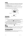
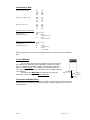
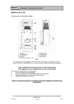
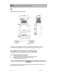
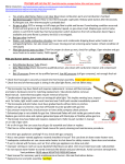
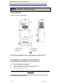
Troubleshoot resources for homeowner
http://waterheatertimer.org/Troubleshoot-Bosch-Tankless-water-heater.html
GOOD.BEETER>BOSCH
Installation / Operating Instructions
Water Wizard 600
Continuous Flow Gas Water Heater
1
2
3
4
Main Cover
Inspection Window
Access Panel
Gas Inlet
5
6
7
8
Cold Water Inlet
Hot Water Supply
Mounting Point
Horizontal Flue
Fig. 1
This appliance must be installed in accordance with the manufacturer’s installation instructions,
AG 601, NZ 5261, AS3500.4.2 and all Local Water,Building and Gas fitting regulations
To be installed and serviced only by an authorised person
This appliance is not suitable for use as a pool heater
The “authorised installing person” is responsible for :
1.
Correct commissioning of this appliance.
2.
Ensure unit performs to the specifications stated on the rating label.
3..
Demonstrate operation of unit to customer before leaving.
4.
Hand these instructions to customer.
Failure to install this appliance in accordance with these installation instructions may
void warranty
In the interest of continued product improvement, Bosch reserves the right to alter
these specifications without notice
BISN0047.0
26/06/2007 Page 1
Installation
Install only on an external wall, as close as possible to the most frequently used hot
tap. Use a heat shield (accessory item part number 9 708 061 400) if the unit is to be installed
on a combustible surface. Allow minimum air gap of 10 mm between the flue and the heat
shield, (refer figure 2).
Ensure that the flue terminal is clear of any combustible material, and avoid
installation in a marine environment.
Install the appliance such that the base of the appliance is not more than 1.3 metres
and not less than 0.5 meters from the ground, and allow for easy access to service heater.
Secure heater to wall using two 10g X 5/16 hex head wood screws (Ramset 610041 or similar).
Locate head of screw in the key hole of the top mounting bracket.
Fig. 2
Pipe Connections
Refer to Fig. 1 for locations
Hot and Cold water ½" male
Natural gas ¾" female
L.P. gas ½" male
A gas cock must be installed in the gas supply line with provision to disconnect the
appliance. Install gate valve or full flow ball valve (fixed mechanism type) in cold water supply.
A non return valve must not be fitted. Example duo valve
We recommend that all hot water pipes be lagged if the runs are long or exposed, and
water-proof lagging should be used on all external hot water pipes. If the water supply
pressure exceeds 80% of the specified maximum, install a pressure limiting valve.
If installing a pressure limiting valve fit a cold expansion valve between the limiting valve and
the appliance. PLV = 500kPa Cold expansion = 700kPa
Refer to AG 601 and AS3500.1 for the relevant pipe size.
NOTE:Service calls for incorrect pipe sizing will NOT be covered under warranty.
Water Filter
If sludge or foreign matter is or may be present in the water supply, it is recommended
that a suitable filter be incorporated in the water supply line to the heater. All pipes should be
well flushed before connection is made.
A water filter/strainer is installed in the inlet of the brass water valve inside the appliance.
Water Temperature Adjustment
Located inside the water heater, immediately below the gas controls, is a water
temperature selector knob.
To increase the water temperature ( decrease water flow ) turn the knob clockwise. To reduce
water temperature ( increase water flow ) turn the knob anti clockwise.
BISN0047.0
26/06/2007 Page 2
Characteristic Data
Pilot orifice diameter (mm)
NG
LPG
TG
TLP
0.30
0.19
0.56
0.56
Burner injector diameter (mm)
NG
LPG
TG
TLP
1.20
0.75
2.15
2.15
Burner pressure ( kPa )
NG
LPG
TG
TLP
0.87
2.60
0.40
0.40
Water flow selector at left hand stop.
Maximum water flow
Temperature rise
Minimum inlet pressure
Water flow selector at right hand stop
Minimum water flow
Temperature rise
Minimum inlet pressure
10 litres / minute
25°C
NG
90 kPa
( 9.0 metres W.G.)
LP
55 kPa
( 5.5 metres W.G.)
4.5 litres / minute
55°C
NG
30 kPa
( 3 metres W.G. )
LP
10 kPa
( 1 metre W.G. )
Refer to rating label located on the bottom right hand corner of the back panel for additional
data.
Freezing Weather
In areas where the atmospheric temperature may drop below 0°C,
the heater must be drained to prevent damage by expansion of freezing
water. For appliances installed in locations where the temperature falls
below 0° C for brief periods , the installation of an EXOGEL expansion
valve, (part number H 707 060 151), will minimise the possibility of damage
to the appliance.
This water heater MUST NOT be installed in areas where the
temperature remains below 0°C for extended periods.
Hot Water
1 Metre
minimum
Exogel
Conversion and Spare Parts
For spare parts or conversion of the heater to operate on a different gas that for which it was
originally manufactured, please contact your local gas authority, authorised service agent or
the manufacturer
BISN0047.0
26/06/2007 Page 3
Operating instructions
Open all hot water taps to expel any air prior to lighting
Remove front cover by loosening the two screws at the lower rear corners of the cabinet.
Check that gas and water valves are open, operate as indicated in Fig. 3
Refit front cover and tighten screws
Fig. 3
Warning - If the pilot light is extinguished, wait 5 minutes before attempting to
relight the appliance. If the appliance does not operate, burns with yellow
flame, leaks water or a gas smell is evident, turn off and contact the local gas
authority, the manufacturer or an authorised service person.
When attempting to light the appliance ensure that all hot water taps are
turned off.
BISN0047.0
26/06/2007 Page 4
Commissioning
Natural Gas Inlet Pressure Adjustment
With the gas supply turned off, remove sealing screw from inlet pressure test point located on
the right hand side of the gas section refer Fig. 4 pos.A, attach manometer. Turn on gas and
light heater. Open hot water tap fully and adjust gas pressure regulator to 0.95 - 1.05 kPa .
Turn off gas and water, remove manometer, replace sealing screw and test for escape.
Natural Gas Burner Pressure Adjustment
Turn off gas supply, loosen captive screw in burner pressure test point, left hand side of
burner manifold refer Fig.5 Pos A, attach manometer turn on hot water tap fully and check
pressure.
Adjust pressure by turning the knurled wheel clockwise to increase gas pressure, anti
clockwise to decrease. refer Fig 4 Pos.E
LP Gas Pressure Adjustment
No adjustment is provided at the appliance for inlet pressure, check cylinder regulator and
pipe sizing.
Adjust burner pressure same as for Natural Gas.
For LP Gas we recommend the installation of two or more supply
cylinders and an auto change over pressure regulator
Fig. 4
Fig 5
Maintenance
We recommend that the appliance be inspected and cleaned by an authorised person
periodically, depending upon the frequency and duration of its operation, but never less than
once a year.
BISN0047.0
26/06/2007 Page 5
Fault Finding.
Problem
Appliance does not light
Pilot lights but no main burner
Smell of gas
Yellow flame
Water leak on top of water valve lid
Possible Cause
Solution
No gas supply
Blocked pilot
Split/Distorted diaphragm
Luminous flame
Loose gas connection
Burner venturi blocked
Damaged O ring
Connect to supply
Replace pilot injector
Replace
Clean burner
Locate leak with soap solution
Clean with venturi brush
Replace O ring, grease with
Unisilkon L641# 8709918413
Excessive pressure
Check water isolating valve.
(Must be gate valve or similar)
Water flow rate set too high
Drain appliance or fit Exogel
expansion valve # H707060151
Check supply regulator and pipe
size
Check appliance regulator
Check thermostat bellows
Check thermostat insert
Set flow rate
Low gas pressure
Check pressure
Thermostat faulty/out of
adjustment
Low water pressure
Replace/Adjust thermostat
Blocked water valve
Clean filter
Blocked heat exchanger
Descale
Clean
Shower goes hot & cold
Blocked shower rose or tap
aerator
Low flow water saver shower rose
Operates only at high water flow
Relief valve spring corroded
Low burner flame, water does not
heat up.
Low water temperature
Low water flow
Cuts off when operating
Operates only with slow light valve
loose
BISN0047.0
Frost damage
Low inlet gas pressure
Low burner pressure
Check and adjust
Replace with less restrictive rose.
Check operation at other tap
Replace valve
Installed incorrectly, cold supply to
hot outlet
Thermostat faulty/out of
adjustment
Correct installation
Wrong thermostat insert
Faulty diaphragm
Fit correct part
Replace
Blocked passage between slow
light & venturi
Clean
Faulty slow light valve
Clean/Replace
Replace/Adjust thermostat
26/06/2007 Page 6
Warranty Details
Your Bosch Hot Water Unit is guaranteed as follows:
For appliances used in domestic applications, ie. normal hot water drawn from household
outlets, the warranty period is Two (2) years parts and labour. Additionally, the heat exchanger is
covered for a period of ten (10) years (parts only).
For appliances used in commercial applications the warranty period is Twelve(12) months
parts and labour including the heat exchanger.
The warranty period commences from the purchase date. Claims for warranty will only be accepted
upon suitable proof of purchase submitted to Robert Bosch (Australia) Pty. Ltd. or an approved Bosch
Service Agent authorised to carry out warranty repairs.
PURCHASER'S STATUTORY RIGHTS
The warranty terms set out below do not exclude any conditions or warranties which may be mandatory
implied by law, and your attention is drawn to the provisions of the Trade Practices Act, 1974, and State
legislation which confers certain rights upon consumers. The ROBERT BOSCH (AUSTRALIA) PTY.
LTD. Warranty supplements these.
EXTRACT OF TERMS OF DELIVERY AND SALE:
Warranty of products marketed by Robert Bosch (Australia) Pty. Ltd. herein referred to as RBAU.
a)
RBAU warrants products marketed by it as free from faults and defects and having the
specified qualities according to the respective state of technology. Notwithstanding that the products
may have been sold by description or sample the products shall be accepted by the Buyer even though
alterations in design or construction have been generally introduced between the date of contract and
the delivery of the products.
b)
The warranty shall be limited to the replacement or repair at the option of RBAU of any
defective products and of such parts of RBAU'
s products as have been damaged in consequence of the
defect despite proper treatment. Parts replaced will not be returned.
c)
I) Repairs and maintenance shall not extend the warranty period of the appliance.
ii) If the product is located outside of the service agent'
s area, the consumer shall be
responsible for the service agent'
s travelling costs, and if necessary the expenses of freight, packing
and charges of a similar nature.
Without limiting the generality of these terms of delivery this warranty shall not apply to products sold in
the following cases :--i)
if the products sold are repaired or altered by any third party without RBAU'
s consent.
ii)
where parts not manufactured or sold by RBAU are used in and replacement or repair.
iii)
if products are not used with proper care and for the purpose for which they are sold and in
accordance with any specified instruction for use.
iv)
if changes occur in the condition or operational qualities of the products due to incorrect
storage or mounting or due to climatic or other influences.
v)
in respect of faulty construction or defects due to the use of unsuitable materials if such
method of construction or use of material has been specified by the Buyer.
vi)
in respect of surface coating and glass damage.
vii)
in respect of the replacement of parts when such replacements are part of the normal
maintenance, service or normal wear and tear.
No servant or authorised service agent has authority to add to or alter the terms of this warranty.
PLEASE NOTE:- If a service call is requested and it is found that it is not a
manufacturing fault, you may be charged for the call even during the warranty period.
ROBERT BOSCH (AUSTRALIA) PTY. LTD. (Incorporated in Victoria) Phone 1300 307 037
1555 Centre Road, Clayton VICTORIA 3169
BISN0047.0
26/06/2007 Page 7