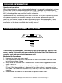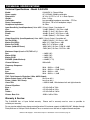
1
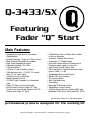
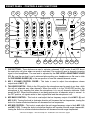
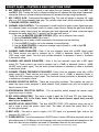
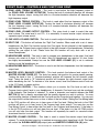
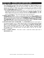
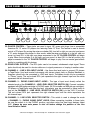
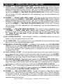
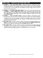
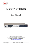
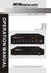
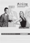
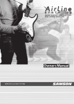
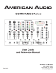
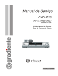
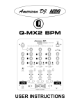
American DJ ® AUDIO
Q-3433/SX
USER INSTRUCTIONS
American DJ
Q-3433/SX
MIC 1
12V LIGHT
PROFESSIONAL PREAMP MIXER
5
0
5
10
0
GAIN
5
10
0
5
10
GAIN
0
GAIN
- 40 30 20 10 7
10
4
2
0
2
4
7 10 +
4
7 10 +
POWER
GAIN
PRE FADER LEVEL (PFL)
-30
+15
-30
MIC TREBLE
+15
-30
TREBLE
+15
-30
TREBLE
+15
-30
TREBLE
L
+15
L
- 40 30 20 10 7
TREBLE
4
2
0
2
R
R
MASTER LEVEL INDICATORS (dB)
-30
-30
+15
MIC MID
+15
-30
MID
+15
-30
MID
+15
-30
MID
ZONE
TREBLE
+15
-30
+15
MID
0
ZONE
BASS
-35
-35
+15
MIC BASS
+15
-35
BASS
+15
-35
BASS
+15
-35
BASS
+15
L
BASS
R
-30
+15
BALANCE
5
OFF
ON
PHONO 1
AUX 1
TALKOVER
MIC 1
PHONO 2
AUX 2
LINE 1
CH 1
PHONO 3
AUX 3
LINE 2
CH 2
PHONO 4
AUX 4
LINE 3
CH 3
LINE 4
STEREO
CH 4
ZONE
VOLUME
MONO
0
MASTER
10
5
5
5
5
5
5
CUE
5
5
CUE
5
5
5
CUE
5
5
0
ON
OFF
5
0
ON
10
MIC 2
VOLUME
1 2 3
4
OFF
FEATHER FADER plus
1 2 3
4
OFF
OFF
“Q” START
PHONE
BASS CUT
ON
ASSIGN CH
“Q” START
FADER “Q” START
djs wanted
ON
OFF
SPLIT CUE
CUE
PGM
OFF
ASSIGN CH
10
CUE LEVEL
CUE
CUE MIXING
PHONES
Q-3433/SX
Featuring
Fader “Q” Start
Main Features:
• Equipped with high quality Crossfader
(Replaceable)
• Optical Detecting Fader for Q-Start Control
• Multi-Channel Assignable Crossfader
• High Power Headphone Output
• Selectable Voltage 115v~230v
• 4 Channel Mixer
• 3 Phono, 4 Line, 3 Auxiliary Inputs
• 3 Microphone Input - (1) XLR/ 1/4" combo
plug, (2) 1/4" Input Jacks
• Volume Control for each Mic
• Master Balance Control
• 12V BNC Light Connector for Gooseneck
Light
• Fader "Q" Start on all four channels
• On/Off Switch Controls Fader "Q" Start
Function (for use with the American DJ CD
Players with Fader "Q" Start)
• -35dB Rotary Kills for Treble, Bass & Mids
on all four channels
• Individual Channel Gain Control
• Convenient "L" Shape Design
• Soft-touch rubber knobs for better control
• Extremely clean signal to noise ratio
• Light Control Signal Output Jack
• Talk Over Button - Reduces channel output
gain by 15dB +/- 2 dB
• Independent Booth Level Output
• Stereo LED Level Indicator
• PFL Level Indicator
• Split Cue Monitoring
• Cue Mixing
• Balanced XLR Master Output
• Stereo/Mono Output Switch
• 4 Signal Output Options - Master (RCA and
Balanced XLR), Booth (RCA) and REC (RCA)
Specifications subject to change without notice.
professional products designed for the working DJ
©American
DJ Supply® - www.americandj.com - Q-3433/SX User Instructions page 2
Index
• Safety Precautions....................................................................................................p.4
• Operating Introduction.............................................................................................p.4
• Functions (Front Panel).............................................................................................p.5
• Inputs & Outputs (Rear Panel)................................................................................p.8
• Set-Up......................................................................................................................p.10
• Replacing the Crossfader........................................................................................p.13
• Operating Determinations......................................................................................p.13
• Technical Specifications........................................................................................p.14
• Warranty & Service.................................................................................................p.14
Important Precautions
1. Be sure to save the packing carton in case
you ever have to return the unit for service.
2. Read all documentation before attempting to
operate your new mixer. Please save all your
documentation for future reference.
3. Do not spill water or other liquids in to or
on to your mixer.
4. Be sure that the local power outlet matches
that of the required voltage for your mixer.
5. Do not attempt to operate this unit if the
power cord has been frayed or broken.
Please route your power cord out of the way
of foot traffic.
6. Always have the front gain controls set to
their lowest level during initial power-up to
prevent speaker damage.
7. Disconnect from main power before making
any type of connection.
8. Do not remove the top cover under any
conditions. There are no user serviceable
parts inside.
9. Disconnect the unit’s main power when left
unused for long periods of time.
©American
Introduction
Introduction:
Congratulations and thank you for purchasing the
American DJ® Q-3433/SX™ mixer. This mixer is a representation of American DJ’s continuing commitment
to producing the best and highest quality products
at an affordable price. This mixer includes several
innovative features that pack a big punch! The
Q-3433/SX™ comes with a 2 year limited
warranty!
Please read and understand this manual completely
before attempting to operate your new mixer. This
booklet contains important information concerning the
proper and safe operation of your new mixer.
Unpacking:
Carefully open and unpack your mixer. Be sure to
save the packaging in case you ever need to return
your unit to the factory. After unpacking, inspect the
mixer for any type of damage that may have occurred
during shipping or transit. If you notice any type of
damage notify your dealer immediately for instructions.
Set-Up Precautions:
Please make any connections before you plug the unit
in. Be sure the Power switch is in the OFF position
before connecting other devices to the mixer. All fader
and volume controls should be set to 0 or minimum
position, before the device is switched on. If the device
has been exposed to drastic temperature fluctuation
(e.g. after transportation), do not switch on the mixer
immediately. The arising condensation of water might
damage your device. Leave the device switched off
until it has reached room temperature.
DJ Supply® - www.americandj.com - Q-3433/SX User Instructions page 3
FRONT PANEL - CONTROLS AND FUNCTIONS
8
7
9
10
11
14
13
12
American DJ
16
Q-3433/SX
MIC 1
6
0
5
10
0
GAIN
12V LIGHT
5
10
0
5
10
GAIN
0
GAIN
- 40 30 20 10 7
10
4
2
0
2
4
7 10 +
4
7 10 +
18
POWER
GAIN
PRE FADER LEVEL (PFL)
-30
+15
-30
MIC TREBLE
+15
-30
TREBLE
+15
-30
TREBLE
+15
-30
TREBLE
L
+15
L
- 40 30 20 10 7
TREBLE
4
2
0
2
R
-30
+15
+15
MIC MID
-30
MID
+15
-30
MID
+15
-30
MID
19
R
MASTER LEVEL INDICATORS (dB)
-30
ZONE
TREBLE
+15
-30
+15
MID
0
4
17
PROFESSIONAL PREAMP MIXER
5
5
15
20
ZONE
BASS
-35
-35
+15
MIC BASS
+15
-35
BASS
+15
-35
BASS
+15
-35
BASS
+15
L
BASS
R
-30
+15
BALANCE
5
OFF
3
ON
PHONO 1
AUX 1
TALKOVER
MIC 1
PHONO 2
AUX 2
LINE 1
CH 1
PHONO 3
AUX 3
LINE 2
CH 2
PHONO 4
AUX 4
LINE 3
CH 3
LINE 4
STEREO
CH 4
ZONE
VOLUME
MONO
0
MASTER
21
10
5
5
5
5
5
2
5
CUE
5
5
CUE
5
5
5
CUE
5
5
0
ON
OFF
1
5
0
ON
10
MIC 2
VOLUME
1 2 3
4
OFF
1 2 3
4
OFF
FEATHER FADER plus
OFF
“Q” START
PHONE
BASS CUT
ON
ASSIGN CH
ON
22
OFF
SPLIT CUE
CUE
PGM
OFF
ASSIGN CH
10
CUE LEVEL
CUE
“Q” START
CUE MIXING
PHONES
FADER “Q” START
30
31
29
28
27
26
25
24
23
1. CUE BUTTONS - These buttons are used to activate a channels "CUE" mode. A red LED above
the cue button will glow when cue mode is activated. Cue mode will send a channels incoming
signal to the headphones. The cue level is adjusted by the CUE LEVEL ADJUSTMENT KNOB
(21). Be sure the cue level is set to minimum before putting your headphones on. Be sure to slide
the CUE MIXING SLIDER (26) to the cue position to hear the selected channel source.
2. MIC 1 VOLUME CONTROL FADER - This fader is used to adjust the microphone volume
output level of MIC 1 (7).
3. TALKOVER SWITCH - While in the ON position the microphone can be used at any time, while
this will not attenuate any other channels. When the switch is in the TALKOVER position, the
microphone is hot, meaning that when the microphone is in use all channels attenuate -15dB
except the MIC. When the microphone is not being spoken into all channels return to normal . In
the OFF position, all signals return to their original level and the microphone is off.
4. MIC BASS CONTROL - This knob is used adjust the low frequency output of both MIC 1 (2) and
MIC 2 (31). Turning the knob in clockwise direction will increase the low frequencies, turning the
knob in a counter-clockwise direction will decrease the low frequencies.
5. MIC MID CONTROL - This knob is used adjust the mid range frequency output of both MIC 1 (2)
and MIC 2 (31). Turning the knob in clockwise direction will increase the mid range frequencies,
turning the knob in a counter-clockwise direction will decrease the mid range frequencies.
©American
DJ Supply® - www.americandj.com - Q-3433/SX User Instructions page 4
FRONT PANEL - CONTROLS AND FUNCTIONS CONT.
6. MIC TREBLE CONTROL - This knob is used adjust the low frequency output of both MIC 1 (2)
and MIC 2 (31). Turning the knob in clockwise direction will increase the high range frequencies,
turning the knob in a counter-clockwise direction will decrease the high range frequencies.
7. MIC 1 INPUT JACK - Combination Microphone Plug. This jack will accept a standard 1/4" male
plug or a XLR 3-pin balanced male plug. The volume output level will be controlled by the MIC
1 VOLUME CONTROL FADER (2).
8. CHANNEL GAIN CONTROL - This adjustment is used to adjust an audio source signal input gain
for a channel. Never use the gain control to adjust output volume. Setting the gain level properly
will ensure a clean output signal. An improper gain level adjustment will send a distorted signal
throughout the entire audio line. To properly set the gain level control:
1. Be sure the MASTER VOLUME CONTROL (27) is set to minimum (zero output).
2. Set the CHANNEL FADER (2) to level 7.
3. Begin play on an audio source connected to the channel you are adjusting.
4. Turn the CUE (1) function on for the channel you are adjusting.
6. Use the GAIN CONTROL to adjust an average output volume of +4 dB in the LED
LEVEL INDICATOR (15).
9. CHANNEL BASS EQUALIZER - Each of the four channels come with a BASS signal output
EQ. These controls are used to increase (up to +15dB) or decrease (down to -35dB) the
LOW range output signal. Turn the knob counter-clockwise to decrease a value or clockwise
to increase a value.
10. CHANNEL MID RANGE EQUALIZER - Each of the four channels come with a MID signal
output EQ. These controls are used to increase (up to +15dB) or decrease (down to -30dB)
the MID range output signal. Turn the knob counter-clockwise to decrease a value or clockwise
to increase a value.
11. CHANNEL TREBLE FREQUENCY EQUALIZER - Each of the four channels come with a HIGH
signal output EQ. These controls are used to increase (up to +15dB) or decrease (down to
-30dB) the HIGH frequency output signal. Turn the knob counter-clockwise to decrease a value
or clockwise to increase a value.
12. SOURCE SELECTOR SWITCH - These are two-position switches. The switches are used to
select the input source assigned to each channel. Each channel may only be assigned one
input source at a time.
13. STEREO/MONO SELECTOR SWITCH - This two-position switch change the master output
signal from mono to stereo.
14. PFL LEVEL INDICATORS - This meter is used to detail the CUE level PFL (pre fader level).
Please Note: PFL is Pre Fader Level. This is the input channel signal level you will
hear in your headphones.
15. MASTER LEVEL INDICATORS - The dual MASTER LEVEL LED indicators along the top of
unit is used to detail the master output level. The meter will detail the output level of the
left and right channels.
16. BNC JACK - This jack is used to supply a 12V DC signal to a gooseneck light, such as the
American DJ® GNL-14.™
17. POWER SWITCH - This is the main power ON/OFF button. A yellow LED below the power switch will
glow when power is ON. Before you turn the power on be sure you have made all connections to the
mixer. Also be sure you amplifiers are tuned off. Remember mixer on first and turned off last
©American
DJ Supply® - www.americandj.com - Q-3433/SX User Instructions page 5
FRONT PANEL - CONTROLS AND FUNCTIONS CONT.
18. ZONE LEVEL TREBLE CONTROL - This knob is used adjust the high frequency output of
the ZONE LEVEL VOLUME OUTPUT(20). Turning the knob in clockwise direction will increase
the high frequency output, turning the knob in a counter-clockwise direction will decrease the
high frequency output.
19. ZONE LEVEL TREBLE CONTROL - This knob is used adjust the low frequency output of the
ZONE LEVEL VOLUME OUTPUT(20). Turning the knob in clockwise direction will increase
the low frequency output, turning the knob in a counter-clockwise direction will decrease the
low frequency output.
20. ZONE LEVEL VOLUME OUTPUT CONTROL - This rotary knob is used to control the zone
level volume. The zone level is not PFL, it is essentially a second master output volume with
separate output volume control.
21. CUE LEVEL VOLUME CONTROL - This knob is used to adjusts the headphone volume level.
22. SPLIT CUE - This button will activate the "Split Cue" function. When used with a set of stereo
headphones, the Split Cue function assign the Cue signal the left channel of the headphones
and assigns the Program (main output) signal to the right channel of the headphones. Essentially
splitting the cue signal in half. Please note that this function will only work with a set of
stereo headphones.
23. HEADPHONES JACKS - This jack is used to connect your headphones to the mixer. Use head
phones only rated at 8 ohms to 16 ohms. Most DJ headphones are rated at 16 ohm, these
are highly recommended. Always be sure the CUE LEVEL VOLUME (21) is set to minimum
before you put the headphones on.
24. HEADPHONES BASS CUT - This button is used to cut the bass frequencies from the headphone
output level.
25. MASTER LEVEL BALANCE CONTROL - This knob controls the balance level output of the
MASTER VOLUME FADER (27). The knob has center lock position for precise center panning.
Turning the knob to the "L" (counter-clockwise) position will increase the left channel output
level. Turing the knob to "R" (clockwise) position will increase the right channel output level,
while decreasing the left. To maintain a true stereo sound, level the balance control knob set
to the 12 O'clock, or center position.
26. CUE MIXING CONTROL - This functions allows you to monitor the Cue level as well as the
Program (main output) level in your headphones. A channels Cue Level may only be monitored
if the channels Cue function is selected. To select a channels cue function depress the CUE
BUTTON (1) that is directly associated with the specific channel you wish to monitor. You may
use the mixing function to blend both the Cue level and the Program level together. You can vary
the output level to either hear more or less of either of the two levels. Sliding the Cue Mixing fader
to the CUE position will allow you to hear more of the Cue level. Sliding the knob to the PGM
position will allow you to hear more of the Program level (main output). You may also use the
Cue Mixing Control to hear either the Cue level or the Program level exclusively. If the fader is
in the full CUE position you will only hear the cue level, if the fader is in the full PGM position
you will only hear the main output. This function will especially be useful for occasions when
an external monitor is not available.
27. MASTER VOLUME CONTROL - This fader is used to control the master output level (main
volume). To avoid distorted output try to maintain an average output signal level +4 dB. This fader
will control the XLR-BALANCED (42) output jacks and MASTER VOLUME RCA (44) jacks.
©American
DJ Supply® - www.americandj.com - Q-3433/SX User Instructions page 6
FRONT PANEL - CONTROLS AND FUNCTIONS CONT.
28. “Q” START ON/OFF - This function works in conjunction with a compatible American DJ® "Q"
series professional CD player. When used with a compatible "Q" series CD player, you can
use the CROSSFADER (30) to start and stop the CD Player. The ON/OFF “Q” START switch
activates this FADER “Q” START feature. When in the ON position, the FADER “Q” START
function allows the fader to return automatically to the CD players preset cue point by simply
sliding the CROSSFADER (30) back and forth.
For example, each time you slide the crossfader to the far left, the "Q" start function will
trigger the play mode for any CD player connected to PLAYER CONTROL "A" (32).
Play will begin at that unit's last set cue point. Turn the "Q" ON/OFF SWITCH to the OFF
position to disengaged “Q” Start function and resume normal fader operation.
29. FADER ASSIGN SWITCH - This is a five position switch that assign a channel to the
CROSSFADER (30). When a channel is assigned to the left side of the CROSSFADER (30) that
channels output level will be controlled by the CROSSFADER (30). Sliding the CROSSFADER
(30) to left position will send full volume output to the MASTER VOLUME LEVEL (27) and sliding
the CROSSFADER (30) to right position will cut that channels volume to MASTER VOLUME
LEVEL (27). The reverse is true for the right channel fader assign switch.
30. FEATHER FADER PLUS™ CROSSFADER - The CROSSFADER blends the output signals of
any channels assigned to "Left" or "Right." When the fader is in the full "Left" position, the output
signal of any channels assigned to "Left" will be controlled by the MASTER VOLUME LEVEL
(27). The same fundamentals will apply for "Right." Sliding the fader from one position to
another will vary the output signals of the "Left" and "Right" channels respectively. When
the crossfader is set in the center position, the output signals of both the "Left" and "Right"
channels will be even.
31. MIC 2 VOLUME CONTROL - This knob is used to control the volume output level of
MICROPHONE 2 (51).
©American
DJ Supply® - www.americandj.com - Q-3433/SX User Instructions page 7
REAR PANEL - CONTROLS AND FUNCTIONS
32
MODEL NO. : Q-3433
POWER SOURCE :
115/230V~ 50/60Hz 20W
SERIAL NO.
L
230V
34
35
36 37
MASTER
LIGHT
CONTROL
ZONE
REC
LINE 4
LINE 3 PHONE 3
AUX 3
L
LINE 2 PHONE 2
AUX 2
GND
AUX 3
CAUTION
RISK OF ELECTRICAL SHOCK
DO NOT OPEN
PLAYER CONTROL
BALANCE OUTPUT
PAS OUVRIR
40
39
LINE 1 PHONE 1
AUX 1
GND
PHONO 3
AUX 2
GND
PHONO 2
AUX 1
MIC 3
MIC 2
PHONO 1
R
AC~
AVIS: RISQUE DE CHOC ELECTRIQUE - NE
38
American DJ
R
115V
33
41
42
43
44
OUTPUT
45
CH 4
CH 3
46
CH 2
47
CH 1
48 49
50
51
32. PLAYER CONTROL - These jacks are used to input 1/8" mono mini plugs from a compatible
American DJ "Q" series CD players also featuring Fader “Q” Start. This feature is used to remote
control a CD player. By moving the mixer crossfader (30) from left to right you can start and pause
a "Q" series compact disc player. In other words, when the mixer crossfader is to the left, and you
move it at least 20% to the right, any player connected to the "B" PLAYER CONTROL will begin
to play. When the crossfader is to the right, and you move it at least 20% to the left position, any
player connected to the "A" PLAYER CONTROL will begin to play. You can create great effects
similar to scratching with this feature.
33. ZONE LEVEL OUTPUTS - The RCA jacks send a low current, unbalanced output signal. These
jacks should only be used for shorter cable runs to signal processors or looping to another mixer.
34. CHANNEL 4 - LINE 4 RCA INPUT JACKS - Use these line level jacks to connect CD players
or Tape Decks. Line level musical instruments with stereo outputs such as Rhythm Machines or
Samplers should also be connected to LINE level inputs. Turntables should only be connected
to "Phono" inputs. The red colored RCA jack represents the right channel input and the white
represents the left channel input.
35. CHANNEL 3 - PHONO 3/AUX3 INPUT JACKS - The type of input must directly reflect the
selected mode of the CHANNEL 3 - LINE LEVEL SELECTOR SWITCH (36). Connect turntables
equipped with MM pickup cartridge to PHONO inputs (All DJ turntable use MM pick-up cartridges).
CD players or Tape Decks and other line level instruments may be connected to these jacks as
long as the CHANNEL 3 - LINE LEVEL SELECTOR SWITCH (36) is in the "AUX 3" position.
The red colored RCA jack represents the right channel input and the white represents the
left channel input.
36. CHANNEL 3 - LINE LEVEL SELECTOR SWITCH - This switch is used to change the mode
of CHANNEL 3 - PHONO 3/AUX3 INPUT JACKS. When connecting turntable to these jacks
be sure the switch is in the PHONO position, and when using line level input devices select
AUX. Always be sure main power is shut off before change the position of the Line
Level Selector Switch.
©American
DJ Supply® - www.americandj.com - Q-3433/SX User Instructions page 8
REAR PANEL - CONTROLS AND FUNCTIONS CONT.
37. CHANNEL 2 - PHONO 2/AUX2 INPUT JACKS - The type of input must directly reflect the
selected mode of the CHANNEL 2 - LINE LEVEL SELECTOR SWITCH (48). Connect turntables
equipped with MM pickup cartridge to PHONO inputs (All DJ turntable use MM pick-up cartridges).
CD players or Tape Decks and other line level instruments may be connected to these jacks as
long as the CHANNEL 2 - LINE LEVEL SELECTOR SWITCH (48) is in the "AUX 2" position.
The red colored RCA jack represents the right channel input and the white represents the
left channel input.
38. CHANNEL 1 - PHONO 1/AUX1 INPUT JACKS - The type of input must directly reflect the
selected mode of the CHANNEL 1 - LINE LEVEL SELECTOR SWITCH (39). Connect turntables
equipped with MM pickup cartridge to PHONO inputs (All DJ turntable use MM pick-up cartridges).
CD players or Tape Decks and other line level instruments may be connected to these jacks as
long as the CHANNEL 1 - LINE LEVEL SELECTOR SWITCH (39) is in the "AUX 1" position.
The red colored RCA jack represents the right channel input and the white represents the
left channel input.
39. CHANNEL 1 - LINE LEVEL SELECTOR SWITCH - This switch is used to change the mode
of CHANNEL 1 - PHONO 1/AUX1 INPUT JACKS. When connecting turntable to these jacks
be sure the switch is in the PHONO position, and when using line level input devices select
AUX. Always be sure main power is shut off before change the position of the Line
Level Selector Switch.
40. AC VOLTAGE SELECTOR - Select between 115V/50Hz or 230V/60Hz. Make sure that the
selector is set to the proper voltage you are using.
41. AC CONNECTION - This connection is used for your detachable AC power cord. Be sure to only
plug your unit in to the recommended power supply.
42. BALANCED XLR MASTER OUTPUTS - The Master Output includes a pair XLR BALANCED
JACKS as well as a pair RCA UNBALANCED JACKS (44). The 3-pin XLR jacks send a high
current balanced output signal. These jacks should be used when you will be driving an amp
or other audio equipment with a balanced input, or whenever you will be running a signal
line greater than 15 feet.
43. LIGHT CONTROL OUTPUT - This jack provides a preset mono audio output signal. There is no
way to adjust this level, however this level will directly reflect the output level of the CHANNEL
SLIDERS (2). This buffered audio output should only be used for light controllers that can accept
an external audio input signal. Great for Touch Panels and Chase Controllers.
44. RCA MASTER OUTPUTS - The Master Output includes a pair XLR BALANCED JACKS (42) as
well as a pair RCA UNBALANCED JACKS. The RCA jacks send a low current unbalanced output
signal. These jacks should only be used for shorter cable runs to signal processors or looping to
another mixer. For cable runs greater than 15 feet use the XLR BALANCED JACKS (42).
45. REC OUT - This is a low current unbalanced output source designed for various tape and CD
recorders. The Record Out (REC OUT) level is dictated by the CHANNEL FADER LEVEL (2), it
is not influenced by the MASTER VOLUME CONTROL (27).
46. CHANNEL 3 - LINE 3 RCA INPUT JACKS - Connect CD players or Tape Decks to these
line level inputs. Line level musical instruments with stereo outputs such as Rhythm Machines
or Samplers should also be connected to LINE inputs. Turntables should only be connected
to "Phono" inputs. The red colored RCA jack represents the right channel input and the white
represents the left channel input.
©American
DJ Supply® - www.americandj.com - Q-3433/SX User Instructions page 9
REAR PANEL - CONTROLS AND FUNCTIONS CONT.
47. CHANNEL 2 - LINE 2 RCA INPUT JACKS - Connect CD players or Tape Decks to these
line level inputs. Line level musical instruments with stereo outputs such as Rhythm Machines
or Samplers should also be connected to LINE inputs. Turntables should only be connected
to "Phono" inputs. The red colored RCA jack represents the right channel input and the white
represents the left channel input.
48. CHANNEL 2 - LINE LEVEL SELECTOR SWITCH - This switch is used to change the mode
of CHANNEL 2 - PHONO 2/AUX2 INPUT JACKS. When connecting turntable to these jacks
be sure the switch is in the PHONO position, and when using line level input devices select
AUX. Always be sure main power is shut off before change the position of the Line
Level Selector Switch.
49. CHANNEL 1 - LINE 1 RCA INPUT JACKS - Connect CD players or Tape Decks to these
line level inputs. Line level musical instruments with stereo outputs such as Rhythm Machines
or Samplers should also be connected to LINE inputs. Turntables should only be connected
to "Phono" inputs. The red colored RCA jack represents the right channel input and the white
represents the left channel input.
50. MIC 3 INPUT JACK - This jack is used to a connect a microphone to the mixer. Connect you mic
to MIC 3 via 1/4 inch (6.3mm) jack. The signals will be controlled by CHANNEL SLIDER 4 (2).
BASS, MID, and TREBLE can be adjusted by the CHANNEL EQ (9, 10, &11).
51. MIC 2 INPUT JACK - This jack is used to a connect a microphone to the mixer. Connect you
mic to MIC 2 via 1/4 inch (6.3mm) jack. The signal level will be controlled by the MIC 2 VOLUME
CONTROL KNOB (31). BASS (4), MID (5), and TREBLE (6) levels can be adjusted.
©American
DJ Supply® - www.americandj.com - Q-3433/SX User Instructions page 10
SET-UP INSTRUCTIONS
INPUTS/OUTPUTS:
OUTPUTS:
The Q-3433/SX allows you two types of output connectors BALANCED XLR (42) and UNBALANCED
RCA (33, 44, & 45). Use these connection to connect the output signal from your mixer to the
inputs of a cross-over, EQ, or other type processor. A balanced connection is recommended for
cable runs longer that 15 feet. When constructing your own XLR cables follow the pin configuration
describe below for proper connectivity. For cable runs shorter than 15 feet you may choose the RCA
unbalanced output option. The unbalanced output option may be more convenient for most users due
to the abundant supply of prefabricated RCA cables on the market.
INPUTS:
All the input options on the mixer are unbalanced RCA's. For best results do not use cable run longer
than 15 feet for any incoming audio source, longer cable runs will result in inferior sound quality.
Male XLR Pin Configuration:
Figure 3
3
1
2
3 Negative (- data)
1 Ground/Return/ 0v)
2 Hot (+ data)
Connections (Refer to the diagrams on pages 8, 12, & 13)
Before you connect the unit's main power supply, be sure local voltage matches that of the required
mixer voltage. Remember the mixer can be selected to operate with either 115v or 230v. Operational
can be changed by the VOLTAGE SELECTOR (40) on the rear of the unit.
Be sure the power switch is in the OFF position before making any type of connections to the mixer.
Also be sure the power on all units being connected to the mixer have been switched off.
Before switch the power on the mixer be sure MASTER VOLUME (27) is turned down and the power
switch to all your amplifier are in the "OFF" position.
Connect the mixers MASTER OUTPUT JACKS (42 & 44) to your audio system. Make sure that the
channels are set properly. When using the BALANCED OUTPUT JACKS (42) be sure your cable
follow the above Pin Configuration (Figure 3).
For recording, connect your tape recorder or cassette deck to the REC OUT JACKS (45). The Record
Out level will not be influenced by the MASTER VOLUME CONTROL (27). The Record Out (REC
OUT) level is dictated by the CHANNEL FADER LEVEL (2).
Connect a microphone to any of the three available MIC INPUT JACKS (7, 50, & 51).
You can connect up to 3 turntables using the PHONO 1 (38), PHONO 2 (37), or PHONO 3 (35)
RCA jacks on the rear panel. The mixer will only accept turntable level signal if the LINE LEVEL
SWITCHES (36, 39, & 48) are in the "PHONO" position.
Connect your tape recorder, tuner, sound effects, CD player, and cassette decks etc. to the RCA
LINE LEVEL INPUT JACKS (34, 46, 47, & 49) on the rear panel. CD players, cassette decks and
other line level instruments may also be connected to the PHONO RCA JACKS (35, 37, & 38) as long
as the LINE LEVEL SWITCHES (36, 39, & 48) are in the "AUX" position.
©American
DJ Supply® - www.americandj.com - Q-3433/SX User Instructions page 11
SET-UP INSTRUCTIONS
Typical Mixer Set-Up
(Inputs)
MODEL NO. : Q-3433
POWER SOURCE :
115/230V~ 50/60Hz 20W
SERIAL NO.
L
230V
115V
American DJ
R
MASTER
LIGHT
CONTROL
DO NOT OPEN
AVIS: RISQUE DE CHOC ELECTRIQUE - NE
REC
LINE 4
LINE 3 PHONE 3
AUX 3
LINE 2 PHONE 2
AUX 2
GND
AUX 3
CAUTION
RISK OF ELECTRICAL SHOCK
ZONE
L
PHONO 3
AUX 2
GND
PHONO 2
AUX 1
MIC 3
MIC 2
PHONO 1
R
AC~
BALANCE OUTPUT
PAS OUVRIR
LINE 1 PHONE 1
AUX 1
GND
PLAYER CONTROL
OUTPUT
CH 4
CH 3
CH 2
CH 1
CASSETTE DECK
T U R N TA B L E
CD PLAYER
T U R N TA B L E
This image details a typical DJ Set Up consisting of a microphone, turntables, CD players, and a tape deck.
Note: Turntables can only be connected to the PHONO LEVEL RCA JACKS (35, 37, & 38). Be sure the LINE
LEVEL SELECTOR SWITCHES (36, 39, & 48) are in the "PHONO" position when using turntables.
©American
DJ Supply® - www.americandj.com - Q-3433/SX User Instructions page 12
SET-UP INSTRUCTIONS
Typical Stereo Set-Up
(Output)
MODEL NO. : Q-3433
POWER SOURCE :
115/230V~ 50/60Hz 20W
SERIAL NO.
L
230V
115V
American DJ
R
MASTER
LIGHT
CONTROL
RISK OF ELECTRICAL SHOCK
DO NOT OPEN
REC
LINE 4
LINE 3 PHONE 3
AUX 3
LINE 2 PHONE 2
AUX 2
GND
AUX 3
CAUTION
AVIS: RISQUE DE CHOC ELECTRIQUE - NE
ZONE
L
PHONO 3
AUX 2
GND
PHONO 2
AUX 1
MIC 3
MIC 2
PHONO 1
R
AC~
PAS OUVRIR
LINE 1 PHONE 1
AUX 1
GND
BALANCE OUTPUT
PLAYER CONTROL
OUTPUT
CH 4
CH 3
CH 2
CH 1
Figure 9
LOUDSPEAKER
LOUDSPEAKER
Typical Balanced Output Set-up
This image details a typical stereo output layout. Note the use of the Balanced XLR Jacks on both the
mixer and the amplifier. Always use the balanced output jacks whenever possible. The balanced output
jacks should always be used for cable runs in excess of 10 feet.
Using the balanced jacks will ensure a clean signal through out the entire audio system.
©American
DJ Supply® - www.americandj.com - Q-3433/SX User Instructions page 13
OPERATING DETERMINATIONS
Operating Determinations
When installing this mixer, please make sure that the device is not exposed to extreme heat, moisture
or dust! There should not be any cables lying around. Doing so endangers you as well as others.
Do not operate the mixer in extremely hot (more than 30°C/100°F) or extremely cold (less than 5°C /
40°F) surroundings. Keep away from direct sunlight and heaters.
Operate the mixer only after becoming familiar with its functions. Do not permit operation by persons
not qualified for operating the mixer. Most damages are the result of unprofessional operation!
Never use spray cleaners to clean the faders! Never use solvents or abrasive detergents to clean
the mixer! It is recommended that you use a soft damp cloth. Please consider that unauthorized
modifications on the device are forbidden due to safety reasons!
CROSSFADER REPLACEMENT INSTRUCTIONS
The crossfader is "Hot Swappable" which means it may be replaced at any time, even when
power is applied. Only replace with American Audio Part Feather Fader Plus. Replacing with
any other model fader may seriously damage your unit.
Replacing the Crossfader
1. Disconnect the mixers main power supply
2. Using a number two Phillips screw driver, unscrew the each of the stainless steel retain screws
that hold the crossfader in place.
3. Gently remove the crossfader from its seated position. You may need to wiggle the crossfader
slightly to remove it.
4. After removing the crossfader, disconnect the ribbon cable that attaches the crossfader to the
PC board. Grasp the crossfader by its base and pull the ribbon cable by its connector not the
actual cables. The connector is designed to only fit one way, so don't worry about the connectors
orientation.
5. Connect the new crossfader to the ribbon cable and replace in reverse order.
©American
DJ Supply® - www.americandj.com - Q-3433/SX User Instructions page 14
TECHNICAL SPECIFICATIONS
Technical Specifications - Model Q-3433/SX
Model:
Power supply:
Dimensions:
Weight:
Crossfader:
Power Consumption:
Headphone impedance:
Q-3433/SX, 4 Channel Mixer
AC 115/230V, 50/60Hz switchable
19" W x 10.75" D x 3.5" H - 6 Rack Spaces
8 lbs. / 3.5 kg
Low grounding impedance crossfader - FF-Plus
5W typical, 7W w/ full headphone output
16 Ohms
Input Sensitivity (Level/Impedence): Note: 0dBV
Line:
Microphone:
Phono:
Aux:
(1Vrms) Output, Crossfader off.
-14 dBV (200mV) / 12K Ohm ± 3dB
-53 dBV (1.2mV) / 3K Ohms ± 3dB
-49 dBV (2.8mV) / 47K Ohms ± 3dB
-14 dBV (200mV) / 47K Ohms ± 3dB
Output Sensitivity (Level/Impedence): Note: 0dBV (1Vrms) Output, Crossfader off.
Rec Out (RCA):
-10dBV (316mV) / 1K Ohms ± 3dB
Master Out (RCA):
0dBV (1V) / 560 Ohms ± 3dB
Master Out (XLR):
0dBV (1V) / 470Ohms ± 3dB
Phones (Load=32 Ohms):
-2dBV (0.4V) /33 Oms, PGM IN ± 3dB
-7dBV (0.4V) /33 Oms, CUE IN ± 3dB
Maximum Output (Load + 47K, THD = 5%)
Rec:
Master (RCA):
Master (XLR):
PHONES (Load=32 ohms):
<
<
<
<
Channel Balance:
Within 3dB
Frequency Response:
Line:
Phono:
Aux:
Microphone:
20Hz
20Hz
20Hz
20Hz
18dBV (8V)
18dBV (8V)
18dBV (8V)
4.6dBV (1.7V)
-
20KHz,
20KHz,
20KHz,
20KHz,
± 1.5dB
± 1.5dB (RIAA)
± 1dB
+1,-3dB
THD - Total Harmonic Distortion (1Khz, 0dBV Output):
Master Output (Load = 47K Ohms):
Less than 0.2%
Phono: (Load = 32K Ohms):
Less than 0.3%
Cross Talk:
< 45dB @ 0dB, 1Khz between left and right channels
Channel Equalizer:
Bass =
Mid =
Treble =
+15/-35± 2dB at 70Hz
+15/-35± 3dB at 1KHz
+15/-35± 2dB at 13KHz
Phones Bass Cut:
-25dB ± 3dB at 70Hz
Warranty & Service:
The Q-3433/SX has a 2-year limited warranty.
validate your warranty.
Please mail in warranty card as soon as possible to
For any service related issues please contact American DJ customer support at (800) 322-6337, Monday through
Friday 9:00 am to 5:00 pm Pacific Standard Time, or contact us on the web at [email protected].
©American
DJ Supply® - www.americandj.com - Q-3433/SX User Instructions page 15
American DJ World Headquarters:
4295 Charter Street Los Angeles, CA 90058 USA
Tel: 323-582-2650 Fax: 323-582-2610
Web: www.americandj.com E-mail: [email protected]