1
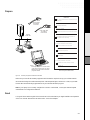
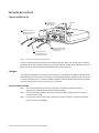
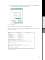
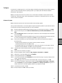
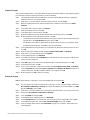
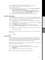
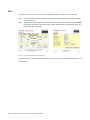
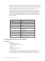
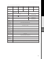
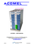
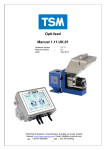
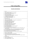
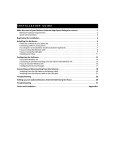
CISCO AIRONET 340 SERIES
ACCESS POINT AND
PC CARD CLIENT ADAPTER
REVIEWER’S GUIDE
C HAPTER 1
Quick Start Instructions for
Access Point and PC Card Client Adapter
Introduction
This guide provides instructions for setting up a simple wireless network and provides background information
on wireless LANs and the development of Cisco’s wireless products.
For the wireless LAN to operate with maximum range and throughput, the equipment must be correctly installed
and configured. The step-by-step instructions in this guide are suitable for most office environments. If your
wired network or your computer equipment presents special challenges, however, you may need to consult your
Network System Administrator. You can also contact a Cisco representative for assistance by calling
800-553-2447 (outside USA, call 408-526-7209), or by sending e-mail to [email protected].
Unpack
Power cord
CISCO AIR
11 Mbps
ONET 340
WIRELE
SS LAN
SERIES
ADAPTE
R
PC Card Client Adapter
Cisco Aironet 340 Series Access Point
CD – Windows 98 and 2000
Software for PC Card Client Adapter
CD – Access Point help
files and documentation
CD – Windows 95 and NT Software
for PC Card Client Adapter
Figure 1-1
Cisco Aironet 340 Series Access Point and PC Card Client Adapter
Unpack your Cisco Aironet 340 Series Access Point and PC Card Client Adapter kit. You should have all of the
above items. If any items are missing, call 800-553-2447 (outside USA, call 408-526-7209).
Quick Start Instructions for Access Point and PC Card Client Adapter
1-2
Prepare
CHECKLIST
SSID - Case-sensitive service set identifier for your
wireless LAN:
Ethernet cable
connected to
wired LAN
(Example: tsunami)
Your laptop’s client name:
(Example: AP340PF)
9-pin serial cable
to configure
Access Point
Existing
wired LAN
Username and password for your network account:
(Example: Patrick, Pat1492)
Your computer name and workgroup name for
Microsoft Windows networking:
(Example: Pat Laptop, Cisco 1)
If you are not connected to a DHCP server:
Unique IP address for Access Point:
(Example: 172.18.4.2)
Default gateway address:
(Example: 85.13.67.5)
Subnet mask:
(Example: 255.255.255.0)
If you are using a Windows NT system:
Available IRQ number (interrupt address):
Laptop –
• Currently configured to connect to the
same wired LAN as the Access Point
• Web browser and terminal-emulation
programs loaded
Figure 1-2
(Example: 11)
Checklist – Information from your
Network System Administrator
Necessary Equipment and Network Information
Make sure you have all the necessary equipment and information required to set up your wireless network.
We recommend using Microsoft Internet Explorer or Netscape Navigator, versions 4.0 or later, as your Web
browser. We recommend using HyperTerminal as your terminal-emulation program.
Note: If your laptop is not currently configured to connect to a wired LAN, contact your Network System
Administrator for configuration assistance.
Read
It is a good idea to read through all of the instructions in this section before you begin installation and operation
of the Cisco Aironet 340 Series Access Point and PC Card Client Adapter.
1-3
Set Up the Access Point
Connect and Power Up
1
4
Point antenna
perpendicular
to the ground.
LED Panel
Connect power cord
between Access Point
and power source.
2
3
Figure 1-3
Connect ethernet cable
between Access Point
and wired LAN.
Connect 9-pin serial
cable between Access
Point and your laptop.
Steps to Connect and Power Up the Access Point
At start-up, all three LEDs on the top of the Access Point slowly blink amber, red, and then green in sequence;
the sequence takes a few minutes to complete. During normal operation, the LEDs blink green. Refer to the user
guide on the Access Point help files and documentation CD for LED descriptions.
Configure
To configure the Access Point to work with your wired LAN, you must assign an IP address and an SSID (Radio
Service Set Identifier) to the Access Point. An SSID is a unique identifier (similar to a password) that must be used
in order for devices like your PC Card Client Adapter to be able to communicate with the Access Point. The SSID
can be any alphanumeric entry up to a maximum of 32 characters.
Assign an IP address and SSID
Step 1.
Open a terminal-emulation program on your laptop. The following instructions describe
HyperTerminal; other terminal-emulation programs are similar.
Step 2.
In the Connection Description window: type a name (for example, AP340), select an icon for the
connection, and click OK.
Step 3.
In the Connect Using pull down menu, select the port to which the cable is connected (for example,
Direct to COM1) and click OK.
1-4
Quick Start Instructions for Access Point and PC Card Client Adapter
Step 4.
In the Port Settings window choose the following settings from the pull down menus: 9600 baud, 8 data
bits, No parity, 1 stop bit, and Xon/Xoff flow control. Click OK.
Figure 1-4
Port Settings Window
Step 5.
Press Enter. The Express Setup screen opens and displays system information.
Note: If you do not see the complete Express Setup screen, press Control/R to refresh the screen or the equal sign
(=) to open the correct screen.
Figure 1-5
Express Set Up Screen
1-5
Note: In the following steps, you do not type the complete word because the system reacts at the first unique letter
(for example, ad for address).
Step 6.
If your wired LAN uses a DHCP server, the Access Point's IP address will be assigned automatically
every time the Access Point is turned on. Write down the IP address and skip to Step 13.
Step 7.
If your LAN does not use a DHCP server, type ad for IP address at the bottom of the Express Setup
screen and press Enter.
Step 8.
From the checklist on page 1-2, type the IP address and press Enter.
Step 9.
Type ga for gateway address and press Enter.
Step 10. From the checklist on page 1-2, type the default gateway address and press Enter.
Step 11. Type su for subnet mask and press Enter.
Step 12. From the checklist on page 1-2, type the subnet mask and press Enter.
Step 13. Type ra for radio SSID and press Enter.
Step 14. From the checklist on page 1-2, type the SSID and press Enter.
Step 15. Type ap and press Enter to apply.
Step 16. Exit the terminal-emulation program and remove the 9-pin serial cable.
You have now completed the required steps to install and configure your Access Point. Use the following steps
to set up the PC Card Client Adapter.
Set Up the PC Card Client Adapter
Install
CAUTION: The following procedures and physical connections apply generally to normal and conventional PC
card slots. In cases of custom or non-conventional equipment, be alert to possible differences in PC Card Client
Adapter slot configurations.
Step 1.
Examine your PC Card Client Adapter. The card is keyed so that it can be inserted only one way into
the PC card slot. One end is a dual-row, 68-pin PC card connector. The other end is a wireless antenna.
The slot in your laptop must be a PC card Type II slot (this includes slots that support both the Type II
and Type III cards). Remove any other PC card from the slot.
Step 2.
For Windows 95 or Windows 98 systems, turn the computer on before inserting the PC Card Client
Step 3.
Hold the PC Card Client Adapter with the logo facing up and insert the card into the slot, applying just
Adapter. For Windows NT systems, turn the computer off before inserting the PC Card Client Adapter.
enough pressure to make sure it is fully seated.
CAUTION: Never force the PC Card Client Adapter into the PC card slot. Forcing it will damage both the PC Card
Client Adapter and the slot. If the PC Card Client Adapter does not easily insert, remove the card and re-insert it.
1-6
Quick Start Instructions for Access Point and PC Card Client Adapter
Configure
Instructions for configuring your PC Card Client Adapter and installing the necessary drivers differ by operating
system. Use instructions that match the operating system of your laptop–either with Windows 98/2000,
Windows 95 or Windows NT.
Note: If your laptop does not have a CD-ROM drive, call the Technical Assistance Center at 800-553-2447
(outside USA, call 408-526-7209). Ask the representative for assistance in locating the drivers for your system
and the Access Point Help files.
Windows 98 Systems
Note: The Windows 98 driver also works with Windows 2000 operating systems.
After you have installed the PC Card Client Adapter, the system automatically detects it, opens a New Hardware
Found window, and starts collecting information for a driver database.
Step 1.
When the Add New Hardware Wizard dialog box opens, it is searching for new drivers. Click Next.
Step 2.
From the next dialog box, select Search for the best driver for your device (Recommended) and click
Next.
Step 3.
Select CD-ROM drive, deselect all other options, insert the PC Card Client Adapter CD for Windows
98, and click Next.
Step 4.
The hardware wizard will find the installation files on the CD and display the search results. When the
PC Card Client Adapter driver is displayed, click Next to copy the required files.
Step 5.
During driver installation, you may be prompted to enter a path to the required client adapter or
Windows 98 files:
• Windows 98 files installed on your laptop are usually located in the folder
C:\Windows\Options\Cabs. Click OK to install.
• If the system prompts you for the Windows CD and the CD-ROM drive on your laptop is drive D,
the path should be D:\WIN98. Click OK to copy the required files.
Step 6.
The Add New Hardware Wizard window opens again indicating the installation is complete. Click
Finish.
Step 7.
Remove the CD and restart your laptop.
Step 8.
When the computer restarts, double-click My Computer, Control Panel, and Network.
Step 9.
Select the PC Card Client Adapter and click Properties.
Step 10. In the Properties window, click Advanced.
Step 11. In the Advanced window, select Client Name. From the checklist on page 1-2, type your laptop’s client
name in the Value dialog box.
Step 12. Select SSID. Type your Access Point’s (case-sensitive) SSID in the Value dialog box. Click OK.
Step 13. If you are not connected to a DHCP server, double-click My Computer, Control Panel, and Network.
Click the Protocols tab and select TCP/IP and Properties. Select Specify an IP address and type the IP
address, subnet mask, and default gateway address of your laptop. Click OK.
Step 14. In the Network window, click OK.
Step 15. When prompted, click Yes to reboot your laptop.
1-7
Windows 95 Systems
After you have installed the PC Card Client Adapter, the system automatically detects it, opens a New Hardware
Found window, and starts collecting information for a driver database.
Step 1.
The Update Device Driver Wizard dialog box opens and indicates that Windows will complete the
installation of the PC Card Client Adapter.
Step 2.
Insert the PC Card Client Adapter CD for Windows 95 and NT, and click Next.
Step 3.
When the Update Device Driver Wizard indicates that it is unable to locate a driver, click Other
Locations.
Step 4.
In the Select other Location window, click Browse.
Step 5.
Select the CD-ROM drive and click OK.
Step 6.
In the Select other Location window, click OK.
Step 7.
When the Update Device Driver Wizard indicates that it has found the driver, click Finish.
Step 8.
When prompted to insert the Windows CD-ROM, click OK.
a) If Windows 95 prompts for files installed on your laptop (located at C:\Windows\Options\Cabs),
type this path in the Copy files from dialog box and click OK.
b) If Windows 95 prompts for the Windows CD and the CD-ROM drive on your laptop is drive D,
the path should be D:\WIN95. Click OK to copy the required files.
Step 9.
In the Systems Settings Change window, you are prompted to restart the computer. Remove CD and
click Yes.
Step 10. When the laptop has restarted, double-click My Computer, Control Panel, and Network.
Step 11. Select the PC Card Client Adapter and click Properties.
Step 12. In the Properties window, click Advanced.
Step 13. In the Advanced window, select Client Name. From the checklist on page 1-2, type your laptop’s client
name in the Value dialog box.
Step 14. Select SSID. Type your Access Point’s (case-sensitive) SSID in the Value dialog box. Click OK.
Step 15. In the Network window, click OK.
Step 16. If you are not connected to a DHCP server, double-click My Computer, Control Panel, and Network.
Click the Protocols tab and select TCP/IP and Properties. Select Specify an IP address and type the IP
address, subnet mask, and default gateway address of your laptop. Click OK.
Step 17. When prompted, click Yes to reboot your laptop.
Windows NT Systems
Note: With Windows NT, install the PC Card Client Adapter with the computer off.
Step 1.
Turn the laptop on and wait for Windows NT to fully start. On your computer desktop, double-click
My Computer, Control Panel and Devices. Scroll down and select PC Card Client Adapter. Click Start
up, select Automatic, and click OK.
Step 2.
Insert the PC Card Client Adapter CD for Windows 95 and Windows NT into your CD-ROM drive.
Step 3.
Double-click My Computer, Control Panel and Network.
Step 4.
Click the Adapter tab and select Add.
Step 5.
In the Select Network Adapter window, click Have Disk.
Step 6.
In the Copy files from box, type the letter of your CD-ROM drive (for example: D:\) and click OK.
Step 7.
In the Select OEM option box, select the PC Card Client Adapter option and click OK.
Step 8.
From the Adapter Setup window, select Client Name and type your computer’s unique name in the
Value dialog box.
1-8
Quick Start Instructions for Access Point and PC Card Client Adapter
Step 9.
Select SSID. Type your Access Point’s (case-sensitive) SSID in the Value dialog box.
Step 10. Select the IRQ number obtained from your system administrator.
Step 11. Click OK and then Close.
Step 12. The TCP/IP Properties windows should open. If not, double-click My Computer, Control Panel and
Network. Select Protocols > TCP/IP > Properties.
• If you are connected to a DHCP server, select Obtain an IP address from a DHCP server.
• If you are not connected to a DHCP server, select Specify an IP address and type the IP Address,
Subnet Mask and Default Gateway address of your laptop. Click OK.
Step 13. When prompted to shutdown and restart your computer, remove the CD and click Yes.
Install the Help System
The Help System allows you to click the Help button on any of your Access Point’s Web pages and access an
HTML online help document explaining the features and functions of that Web page. The Help System files are
provided on the supplied CD-ROM. To install the Help System, follow these steps:
Step 1.
Open your Web browser. We recommend using Microsoft Internet Explorer or Netscape Navigator,
versions 4.0 or later.
Step 2.
Type the Access Point’s IP address from the previous section in the browser address line and press Enter.
Step 3.
Click the Setup button to access the Setup Web page.
Step 4.
Click the Web Server link in the Services section to access the Web Server Setup Web page.
Step 5.
Place your cursor in the Default Help Root URL box. (This entry tells the system where to find the help
files.)
Step 6.
Type the path to your CD-ROM drive and the help files (for example, if your CD-ROM drive is D:,
then type file:///D:\Aironet\Help)
Note: You may choose to copy the Help files to your hard drive or file server. You would then need to edit the
path accordingly.
Step 7.
Click Apply.
Install Utilities
Install the Aironet Client Utilities (ACU), Link Status Meter (LSM), and Client Encryption Manger (CEM)
utilities. Installing utilities is optional unless your network uses Wired Equivalent Privacy (WEP). If WEP is
enabled, all devices in the network must have the same WEP code, which you set using the CEM utility. The ACU
and LSM utilities provide troubleshooting and status information, but are not required.
Note: Refer to Using the Cisco Aironet 340 Series PC Card Client Adapters on the PC Card Client Adapter CD
for specific instructions on how to use each utility.
Step 1.
Step 2.
Insert the CD for your operating system into your CD-ROM drive.
Select Start > Run and type the following path (where D is the letter for your CD-ROM drive):
D:\utils\setup.exe
Step 3.
Follow the set up instructions on the screen to complete the installation.
Note: Contact your IS department if you have a problem connecting to the network.
1-9
Test
To test that your Access Point and PC Card Client Adapter are properly configured, follow these steps:
Step 1.
Open your Web browser. We recommend using Microsoft Internet Explorer or Netscape Navigator,
versions 4.0 or later.
Step 2.
Type the Access Point IP address from the previous section in the browser address line and press Enter.
Depending on the method used to assign the IP address, either the Summary Status Web page or the
Express Setup Web page opens.
Figure 1-6
Summary Status and Express Setup Web Pages
Congratulations! You have now created a wireless LAN using Cisco Aironet 340 Series Access Point and PC Card
Client Adapter.
1-10
Quick Start Instructions for Access Point and PC Card Client Adapter
C HAPTER 2
Cisco Aironet 340 Series Product Features/
Specifications
Cisco Aironet 340 Series Access Points and PC Card Client Adapters
The Cisco Aironet 340 Series is a comprehensive family of PC Card Client Adapters and Access Points that
enables organizations to integrate the freedom and flexibility of wireless local-area networking into their
information systems.
Main Features
• 11 Mbps Performance
• Security equivalent to wired networks
• Wireless freedom and flexibility
• IEEE 802.11b interoperability
The Cisco Aironet 340 Series PC Card Client Adapters and Access Points are designed to meet the mobility,
performance, security, interoperability/management, and reliability requirements of in-building wireless
local-area networks (WLANs) within enterprise-wide information infrastructures or as free-standing, all-wireless
networks. The Cisco Aironet 340 Series products provide value-added features that are ideal for:
• IT professionals or business executives who want mobility within the enterprise, as an addition or alternative
to wired networks
• Business owners or IT directors who need flexibility for frequent LAN wiring changes, either throughout the
site or in selected areas
• Any company whose site is not conducive to LAN wiring because of building or budget limitations, such as
older buildings, leased space, or temporary site
The Cisco Aironet 340 Series includes a complete line of client adapters, including PC Card Client Adapter,
Personal Computer Interface (PCI), and Industry-Standard Architecture (ISA) cards for both notebook and
desktop wireless connectivity. Cisco Aironet 340 Series Access Points offer unprecedented management features,
including a full-featured Web interface to simplify the navigation of the network, and a variety of antenna options
to fit virtually any environment.
Based on direct sequence spread spectrum (DSSS) technology and operating in the 2.4 GHz band, the Cisco
Aironet 340 Series provides an Ethernet-like data rate of up to 11 megabits per second (Mbps). The high speed
and throughput of the Cisco Aironet 340 Series enables the wireless transfer of bandwidth-intensive data such as
multimedia streams and large data files within the enterprise.
Cisco Aironet 340 Series Product Features/Specifications
2-11
Understanding the security requirements of both small businesses and the enterprise, Cisco provides up to 128-bit
Wired Equivalent Privacy (WEP), an optional security mechanism defined within the IEEE 802.11 standard that
makes the link integrity of the wireless medium equal to that of a cable. WEP is integrated with standard
authentication features providing a level of data security equal to traditional wired LANs.
For investment protection, the Cisco Aironet 340 Series conforms to the IEEE 802.11b standard, ensuring
interoperability with equipment available from a variety of vendors. The Cisco Aironet 340 Series is fully
compatible with most popular network operating systems and delivers both Simple Network Management
Protocol (SNMP) and Web-based management features. The Cisco Aironet 340 Series can be seamlessly
integrated into wired Ethernet networks, as a complement or alternative to the best-of-class wired LAN products
offered by Cisco Systems.
Table 2-1 Cisco Aironet 340 Series Specifications
Data Rates Supported
1, 2, 5.5 and 11 Mbps
Network Standard
IEEE 802.11b
Frequency Band
2400-2483.4 MHz
Wireless Medium
Direct Sequence Spread Spectrum (DSSS)
Media Access Protocol
Carrier sense multiple access with collision avoidance
(CSMA/CA)
Network Operating Systems Supported
Microsoft Windows 2000, 98, 95 NT, and CE
Modulation
DBPSK@ 1 Mbps
DQPSK@ 2 Mbps
CCK @ 5.5 and 11 Mbps
Operating Channels
11 channels (U.S., Canada, and Japan);
13 channels (ETSI)
Non-Overlapping Channels
Three
Roaming
IEEE 802.11b compliant with Cisco enhanced roaming
features
Warranty
One year: Access Points
Lifetime limited: Client Adapters
Cisco Aironet 340 Series PC Card Client Adapters
Main Features
• High speed
• Excellent price/performance
• Full-featured utilities and robust management
• Secure transmission
• Long range
• Fully compliant with 802.11b standard
• Field-proven reliability
Cisco Aironet 340 Series PC Card Client Adapters couple the mobility, freedom, and flexibility of wireless
local-area networking with the bandwidth required by enterprise-wide information systems. With
wireless-enabled client PCs, users with laptop, notebook, and hand-held devices can move freely within a campus
2-12
Cisco Aironet 340 Series Product Features/Specifications
environment while maintaining uninterrupted access to centrally located data. With wireless PCI and ISA
Adapters, desktop PCs can be quickly added to a LAN without expensive, time-consuming, and often impractical
cable runs and drops. With wireless, as an organization grows, reorganizes, or even changes location, clients can
be quickly relocated without a loss of productivity.
Now with 11 Mbps of bandwidth, the benefits of wireless do not come at the expense of the data rate and
throughput required by data-intensive applications. With the Cisco Aironet PC Card Client Adapters, users don't
sacrifice anything; they experience the network performance they have come to expect - without the constraints
and inflexibility of a wired connection.
All Cisco Aironet 340 Series PC Card Client Adapters feature antennas that provide the range and reliability
required for data transmission and reception in larger indoor facilities. The internal dual diversity antennas of
the PC Card Client Adapter automatically toggle to select the antenna receiving the strongest signal as the user
moves within a facility. The fixed, integrated antenna is rugged enough to withstand the rigors of mobile
computing and compact enough to stay out of the way, extending only an inch outside the PC card slot. The
external antenna, standard with the PCI and ISA Adapters, is optimized for transmission from a stationary
system and fits neatly behind the PC.
Up to 128-bit wired equivalent privacy (WEP) encryption security is available to provide data security that is
comparable to traditional wired LANs. Cisco includes a complete set of device drivers to make installation
trouble-free in a full range of systems. Easy-to-use site survey tools produce graphical information, including
signal strength. To further facilitate installation, Cisco provides a suite of integrated utilities for Windows-based
configuration, management, and diagnostics.
Cisco Aironet 340 Series Access Points
Main Features
• Manageability
• Easy integration and configuration
• Multiple configuration options
• Fully compliant with 802.11b standard
Cisco Aironet 340 Series Access Points perform functions similar to a hub in a wired network; in addition, they
add the vital price/performance benefits of security, management features and mobility services. For example, the
innovative roaming functionality provided by Cisco Aironet Access Points enable users equipped with wireless
PC Card Client Adapters to freely move throughout a facility while maintaining seamless, uninterrupted access
to the network. The Cisco Aironet 340 family of Access Points features easy integration to a wired network
backbone, flexible configuration, management capabilities and a wide range of product configurations.
The Cisco Aironet 340 Series Access Points integrate easily into 10- and 100-Mbps Ethernet networks via a single
autosensing RJ-45 port. The Access Point acts as a bridge, forwarding at media speed between the Ethernet
CSMA/CD protocol and the wireless CSMA/CA protocol, seamlessly integrating wireless functionality into a
wired infrastructure. The Cisco Aironet 340 Series Access Points may be configured locally via serial port or
remotely over the LAN; they provide the option of a Web browser or console management interface.
2-13
The Cisco Aironet 340 Series management system offers IS professionals complete control over Access Point
settings and operational information. Setting security levels, addresses, transmission channels, data rates and
other options can be done quickly through either management interface. The management system captures vital
operational data that may be viewed as an event log within the management system or exported to a
Management Information Base (MIB) for analysis by an SNMP-compliant system.
Every in-building wireless deployment presents different transmission considerations: varying building sizes,
construction materials and interior divisions impact the deployment of a wireless LAN. To ensure maximum
network coverage efficiency in a variety of information systems and facilities, Cisco offers Access Points with
three distinct antenna configurations. For small to medium-sized businesses and similar organizations, Cisco
provides an Access Point with a single, integrated external antenna that combines needed features with more
stringent budget requirements. For larger organizations, Cisco provides Access Points with integrated,
dual-diversity external antennas that address the multipath problems associated with larger facilities. Finally, for
the most challenging installations, Cisco provides Access Points with dual reverse-polarity TNC connectors.
These connectors allow the planner to select from more than 20 different omnidirectional, patch, yagi and
parabolic antennas to engineer the coverage needed within almost any facility. To meet the security needs of
organizations around the world, Access Points are available with up to WEP-128 encryption.
2-14
Cisco Aironet 340 Series Product Features/Specifications
Table 2-2 Cisco Aironet 340 Series Access Point Specifications
Feature
AIR-AP341S1C
AIR-AP342E2C
AIR-AP341E2C
AIR-AP342E2R
AIR-AP341E2R
Encryption
40-bit WEP
128-bit WEP
40-bit WEP
128-bit WEP
40-bit WEP
Power
Requirements
110-120V/220-240V
110-120V
110-120V/220-240V
110-120V
110-120V/220-240V
Antenna
Integrated single
2.2 dBi dipole (no
antenna diversity)
Optional (none supplied with unit)
Dual RP-TNC connectors
with diversity support
None
Optional Antenna
Connector
Maximum Clients
Integrated (nonremovable)
dual 2.2 dBi dipole with diversity support
10
2048
Range at 1 Mbps
(typical)
1300 ft. (400m) open environment; 250 ft (77m) office
1500 ft. (460m) open environment;
300 ft (90m) office
Range at 11 Mbps
(typical)
300 ft. (90m) open environment; 80 ft (25m) office
400 ft. (120m) open environment;
100 ft (30m) office
Network Protocols
Supported
LED Indicators
Local
Configuration
Complies with IEEE 802.3
Status, network activity and RF Activity
Direct console port (serial EIA-232 DB-9 female)
Remote
Configuration
HTTP, Telnet, FTP, or SNMP
Automatic
Configuration
BOOTP and DHCP
Receive
Sensitivity
-90dBm @ 1 Mbps, -88dBm @ 2 Mbps, -87dBm @ 5.5 Mbps, -83dBm @ 11 Mbps
Output Power
30 mW (U.S., Canada, ETSI) 4.5 mW/MHz (EIRP, Japan)
Power
Consumption
5V±5% @ 800 mA
SNMP Compliance
Certifications
Operating
Temperature
Humidity (noncondensing)
Dimensions
Weight
MIB I, MIB II
FCC Class A, FCC Part 15.247, Canada ICES Class B, CE, UL, CSA;
Call for other information outside the U.S.
32° to 131° F (0 to 55° C)
10 to 90%
6.3 x 4.72 x 1.45 in. (16 x 12 x 3.68 cm)
12.3 oz. (350g), excluding power supply
2-15
Glossary
DSSS
A type of spread spectrum radio transmission that spreads its signal continuously over a wide frequency
band.
Long range
A linear measure of the distance that a transmitter can send a signal.
Bandwith
Specifies the amount of the frequency spectrum that is usable for data transfer; it identifies the maximum
data rate that a signal can attain on the medium without encountering significant loss of power.
Dual diversity antennas
An intelligent system of two antennas that continually senses incoming radio signals and automatically
selects the antenna best positioned to receive it.
Multi-path
The echoes created as a radio signal bounces off physical objects.
Dual reverse-polarity
Connector types unique to Cisco Aironet radios and antennas. Part 15.203 of the FCC rules covering
spread-spectrum devices limits the types of antennas that may be used with transmission equipment. In
compliance with this rule, Cisco Aironet radios and antennas are equipped with unique connectors to prevent
attachment of nonapproved antennas to radios.
2-16
Cisco Aironet 340 Series Product Features/Specifications
C HAPTER 3
Background
Cisco and Aironet History
Aironet was incorporated in 1993 as an independently run subsidiary of Telxon Corporation, an early leader in
the hand-held data collection market. Our technology and intellectual property roots date back to 1986 with the
founding of Telesystems, a pioneer in wireless LAN technology. Telxon acquired Telesystems in 1992, which
shortly thereafter became the foundation for Aironet. In August of 1999, Aironet became a publicly traded
company with a successful initial public offering. In March of 2000, Aironet was acquired by Cisco Systems.
Today Cisco is a leading provider of high-speed, standards-based WLAN solutions. We are a major contributor
to the industry’s development of the IEEE 802.11b wireless LAN standard and the first company to bring a full
range of 802.11-compliant, high-speed 11 Mbps products to market. Our products are marketed worldwide
through distributors, value-added resellers (VARs) and OEM partners.
Introduction to Wireless LANs
The wireless LAN market emerged in the mid-1980s when real-time data collection and inventory management
became business necessities. Retailers needed to know instantly what was selling—or not selling—on their
shelves. Industries needed to manage inventory “just in time” for manufacturing to fill actual orders. And
everyone was demanding “electronic data interchange.”
Early wireless portable systems were based on narrow-band UHF in the 450-470 MHz frequency band. In some
countries, including the United States, radio-based installations require local site licenses from government
agencies. In 1985 the FCC authorized unlicensed usage of spread spectrum radios in the Industrial, Scientific and
Medical (ISM) bands, including 902-928 MHz, 2.400-2.4835 GHz and 5.725-5.875 GHz.
Three years later, the first FCC-certified 900-MHz spread-spectrum radio for wireless systems was introduced by
Telesystems SLW Inc. of Markham, Ontario (acquired by Telxon, Aironet’s founding company, in 1992 via a
stock acquisition following several years of joint product ventures). This early 900- MHz, spread-spectrum radio
delivered the higher data rates needed for “real-time” data collection and was soon integrated into a wide array
of devices serving retail and manufacturing applications.
In 1994 wireless LAN communications took another leap forward. Due to advances in RF technology, radio
components were getting smaller, faster, and cheaper. Now the wireless industry could reasonably produce 2.4
GHz spread-spectrum radios capable of sustaining 1 or 2 Megabits per second (Mbps), more than twice the speed
of 900 MHz devices.
Background
3-17
Besides faster data transmissions, 2.4 GHz radios offer an even bigger advantage—unlike 900 MHz, the 2.4 GHz
is unlicensed and available in most of the world. Because of this worldwide acceptance, the Institute of Electrical
and Electronics Engineers (IEEE) Standards Activity Board 802.11 committee designated 2.4 GHz as the RF band
for emerging standards for wireless LAN specifications.
In June 1997 the IEEE Standards Activity Board approved the 802.11 wireless LAN standard. This long-awaited
standard will allow mobile wireless LAN components, from different manufacturers that are 802.11 compliant,
to be used with the same wireless infrastructure. More and more 802.11-compliant products are coming onto
the market. The entire industry is now focusing on the implementation of IEEE 802.11 wireless networks,
conformance testing, and proving interoperability between multiple vendors.
As a champion for industry standards, Cisco intends to fully participate in all pertinent conformance and
interoperability testing of wireless LAN products. In April of 2000, Cisco was in the first group of wireless LAN
vendors to be awarded the wi-fi™ certification of inter-operability for IEEE 802.11b products by the Wireless
Ethernet Compatibility Association (WECA). WECA was founded in 1999 to certify inter-operability of IEEE
802.11b wireless LAN products.
Real-world throughput vs. idealistic data rates
When comparing the performance of communications systems, it’s important to make sure the systems are on a
level playing field. Two terms in particular can lead to a lopsided understanding of system speed—“data rate”
and “throughput.”
Data rate in communications systems is not a measure of speed. The raw data rate actually describes the capacity
of a system—the size of the pipe.
Throughput describes how much useful data is transferred through a system in a given period of time, and is a
better measure of the actual speed of a system.
Throughput will always be less than the raw data rate. The difference between the two measures is due to
protocol overhead and transmission errors. The real data that you want to send over the network is encapsulated
in packets that contain addressing and other protocol control information. Each protocol layer adds its own
protocol functions, and therefore its own overhead.
In a world dominated by the Internet, everyone uses the TCP/IP protocol stack. Therefore, a reasonable
real-world test of the “speed” of a network is to measure a file transfer time over a network using FTP, the File
Transfer Protocol. Cisco bases most network performance comparisons on FTP file transfers. There are at least
five levels of protocol overhead involved in that transfer: the FTP protocol, the UDP protocol, the IP protocol,
the LLC protocol, and the MAC and PHY for the particular network. This is a good test for most users, but the
results are always less than the throughput claims put forward by many marketing departments.
To avoid protocol overhead and show their network in a more favorable light, companies usually conduct very
low-level tests of their products. The resulting marketing claim is usually based on transmitting frames directly
over the MAC interface without any higher level protocols. This is more impressive than the FTP test, but still
less than the raw data rate.
3-18
Background
C HAPTER 4
Safety and Compliance
Safety Information
The FCC with its action in ET Docket 96-8 has adopted a safety standard for human exposure to radio frequency
(RF) electromagnetic energy emitted by FCC certified equipment. Cisco Aironet 340 Series products meet the
uncontrolled environmental limits found in OET-65 and ANSI C95.1, 1991. Proper operation of this radio
according to the instructions found in this Reviewer’s Guide will result in user exposure that is substantially
below the FCC recommended limits.
• Do not touch or move antenna(s) while the unit is transmitting or receiving.
• Do not hold any component containing the radio such that the antenna is very close or touching any exposed
parts of the body, especially the face or eyes, while transmitting.
• Do not operate a portable transmitter near unshielded blasting caps or in an explosive environment unless it is
a type especially qualified for such use.
• Do not operate the radio or attempt to transmit date unless the antenna is connected; if not, the radio may be
damaged.
• Antenna use:
– Always orient a dipole antenna such that it is at least 6 inches (15 cm) away from your body.
– High-gain, wall-mount or mast-mount antennas are designed to be professionally installed and should be
located at a minimum distance of 12 inches (30 cm) or more from your body. Please contact your professional
installer, VAR, or antenna manufacturer for proper installation requirements.
– Warning for laptop users: In order to comply with the FCC RF exposure limits, it is recommended when using
a laptop with a PC Card Client Adapter, that the adapter’s integrated antenna should not be positioned closer
than 2 inches (5 cm) from your body or nearby persons for extended periods of time while it is transmitting
(or operating). If the antenna is positioned less than 2 inches (5 cm) from the user, it is recommended that the
user limit exposure time.
Compliance Information
Federal Communication Commission Declaration of Conformity Statement
This device complies with Part 15 rules. Operation is subject to the following two conditions:
1. This device may not cause harmful interference, and
2. This device must accept any interference received, including interference that may cause undesired operation.
Safety and Compliance
4-19
This equipment has been tested and found to comply with the limits of a Class B digital device, pursuant to Part
15 of the FCC Rules. These limits are designed to provide reasonable protection against harmful interference
when the equipment is operated in a residential environment. This equipment generates, uses, and radiates radio
frequency energy, and if not installed and used in accordance with the instructions, may cause harmful
interference. However, there is no guarantee that interference will not occur. If this equipment does cause
interference to radio or television reception, which can be determined by turning the equipment on and off,
the user is encouraged to correct the interference by one of the following measures:
• Reorient or relocate the receiving antenna.
• Increase separation between the equipment and receiver.
• Connect the equipment into an outlet on a circuit different from which the receiver is connected.
• Consult the dealer or an experienced radio/TV technician.
Department of Communications—Canada Canadian Compliance Statement
This class B Digital apparatus meets all the requirements of the Canadian Interference-Causing Equipment
Regulations.
Cet appareil numerique de la classe B respecte les exigences du Reglement sur le material broilleur du Canada.
This device complies with RSS-210 of Industry Canada. Operation is subject to the following two conditions:
1) this device may not cause harmful interference, and 2) this device must accept any interference received,
including interference that may cause undesired operation.
The device is certified to the requirements of RSS-139-1 for 2.4 GHz spread spectrum devices. The use of this
device in a system operating either partially or completely outdoors may require the user to obtain a license
for the system according to the Canadian regulations. For further information, contact your local Industry
Canada office.
European Telecommunications Standards Institute Statement
of Compliance Information to User
This equipment has been tested and found to comply with the European Telecommunications Standard ETS
300.328. This standard covers Wideband Data Transmission Systems referred to in CEPT recommendation T/
R 10.01.
This type accepted equipment is designed to provide reasonable protection against harmful interference when the
equipment is operated in a commercial environment. This equipment generates, uses, and can radiate radio
frequency energy, and if not installed and used in accordance with the instruction manual, may cause harmful
interference to radio communications.
4-20
Safety and Compliance
C HAPTER 5
Technical Support
If you need technical assistance with a Cisco Aironet product, contact our Technical Assistance Center:
Phone: 800-553-2447 (outside USA, call 408-526-7209)
E-mail: [email protected]
Web: http://www.cisco.com
Service hours: 24 hours a day
Technical Support
5-21
Corporate Headquarters
Cisco Systems, Inc.
170 West Tasman Drive
San Jose, CA 95134-1706
USA
http://www.cisco.com
Tel: 408 526-4000
800 553-NETS (6387)
Fax: 408 526-4100
European Headquarters
Cisco Systems Europe
11, Rue Camille Desmoulins
92782 Issy Les Moulineaux
Cedex 9
France
http://www-europe.cisco.com
Tel: 33 1 58 04 60 00
Fax: 33 1 58 04 61 00
Americas Headquarters
Cisco Systems, Inc.
170 West Tasman Drive
San Jose, CA 95134-1706
USA
http://www.cisco.com
Tel: 408 526-7660
Fax: 408 527-0883
Asia Pacific Headquarters
Cisco Systems Australia Pty., Ltd.
Level 17, 99 Walker Street
North Sydney
NSW 2059 Australia
Tel: 61 2 8448 7100
Fax: 61 2 9957 4350
Cisco Systems has more than 200 offices in the following countries. Addresses, phone numbers, and fax numbers are listed on the
Cisco Connection Online Web site at http://www.cisco.com/go/offices.
Argentina • Australia • Austria • Belgium • Brazil • Canada • Chile • China • Colombia • Costa Rica • Croatia • Czech Republic • Denmark • Dubai, UAE
Finland • France • Germany • Greece • Hong Kong • Hungary • India • Indonesia • Ireland • Israel • Italy • Japan • Korea • Luxembourg • Malaysia
Mexico • The Netherlands • New Zealand • Norway • Peru • Philippines • Poland • Portugal • Puerto Rico • Romania • Russia • Saudi Arabia • Singapore
Slovakia • Slovenia • South Africa • Spain • Sweden • Switzerland • Taiwan • Thailand • Turkey • Ukraine • United Kingdom • United States • Venezuela
Copyright © 2000 Cisco Systems, Inc. All rights reserved. Printed in the USA. BPX, Catalyst, Cisco, Cisco IOS, Cisco Systems, and the Cisco Systems logo are registered trademarks of Cisco Systems, Inc. or its
affiliates in the U.S. and certain other countries. All other trademarks mentioned in this document are the property of their respective owners. The use of the word partner does not imply a partnership relationship
between Cisco and any of its resellers. (0005R)
07/00 BW6342