1
Owner's
Manui
®
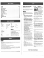
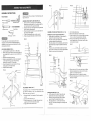
1 HP (Max. Developed)
2 Speeds
1410 and 2600 F.P.IVI.(No Load)
Leg Stand
SAW
Model No.
137.224320
E82358
37J5 LISTED
CAUTION:
®
•
•
,,
Before using th!s band saw,
read this manual and follow
all its Safety Rules and
Operating Instructions.
Safety Instructions
Installation
Operation
Maintenance
o Parts List
Customer
Help
Line
1 =800-843-1682
Sears,
Roebuck
Part No. 3BS12401
and Co., Hoffman
Estates,
mL60179
USA
SECTION
PAGE
Warranty .........
..............
.........................................
Product Specifications .....................................................
Safety Instructions ........................................................
Accessories and Attachments ...............................................
Carton Contents ...........................................................
Know Your Band Saw ......................................
................
Glossary of Terms ..................................................
Assembly and Adjustments .........................
.......................
Operation ..............................................................
Maintenance ............................................................
Troubleshooting guide ....................................................
Parts ..................................................................
MOTOR
Power source
.........
Horsepower
..........
Speeds
Low .........
High .........
................
Type
DRIVE
BELT ............
CUTTING
Throat
Height
BLADE
Width
Length
120 V AC, 60 HZ, 7 AMPS
1 HP (Max. developed)
1410ERM.
(Feet per minute)
2600 RRM.
Induction
DUST COLLECTION
NET WEIGHT
...........
13" x 13"
0 - 45 ° Right
.....
Yes
!45.5
12"
...............
5"
...............
1/8", 1/4". 3/8';. 1/2"
;! i
BEFORE
To avoid electrical hazards, fire hazards, or damage to the
tool, use proper circuit protection.
Use a separate electrical circuit for your tools.
Your band saw is wired at the factory for 120V operation.
Connect to a 120',/, 15 AMP time delay fuse or circuit
breaker. To avoid shock or fire, replace power cord
immediately if it is worn, cut or damaged in any way.
80"
Some dust created by power sanding sawing, grinding, drilling, and other construction activities contains chemicals
known [to the State of California] to cause cancer, birth defects or other reproductive harm. Some examples of these
chemicals are:
® Lead from lead-based paints.
@ Crystalline silica from bricks and cement and other masonry products, and
@ Arsenic and chromium from chemically-treated lumber.
Your risk from these exposures varies, depending on how often you do this type of work. To reduce your exposure to
these chemicals: work in a well ventilated area, and work with approved safety equipment, such as those dust masks
12.
USING THE BAND SAW
Safety is a combination of common sense, staying alert and
knowing how to use your band saw.
To avoid mistakes that could cause serious injury, do not
plug the band saw in until you have read and understood the
following:
1.
READ and become familiar with this entire instruction
manual. LEARN the tool's applications, limitations, and
possible hazards.
2.
KEEP GUARDS IN PLACE and in working order.
3.
REMOVE ADJUSTING KEYS AND WRENCHES. Form
the habit of checking to see that keys and adjusting
wrenches are removed from the tool before turning ON.
4.
KEEP WORK AREA CLEAN. Cluttered areas and
benches invite accidents.
5.
DON'T USE IN A DANGEROUS ENVIRONMENT. Don't
use power tools in damp or wet locations, or expose
them to rain. Keep work area well lighted.
6.
KEEP CHILDREN AWAY. All visitors should be kept at a
safe distance from the work area.
7.
MAKE WORKSHOP KID-PROOF with padlocks, master
switches, or by removing starter keys.
LB (66 Kg.)
A 26
CAPACITY
...............
..............
TABLE
Size ................
Tilt .................
2
2
3
6
6
8
...... 9
10
16
18
20
22
GENERAL SAFETY INSTRUCTIONS
8.
DON'T FORCE THE TOOL. It will do the job better and
safer at the rate for which it was designed.
9.
USE THE RIGHTTOOL. Don't force the tool or the
attachment to do a job for which it was not designed.
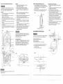
WEARYOUR
ALWAYS WEAR EYE
PROTECTION. Any band saw
can throw foreign objects into the
eyes which could cause
permanent eye damage.
ALWAYS wear Safety Goggles
(not glasses) that comply with
ANSI safety standard Z87.1, Everyday eyeglasses have
only impact-resistant lenses. They ARE NOT safety
glasses. Safety Goggles are available at Sears.
NOTE: Glasses or goggles not in compliance with ANSI
Z87,1 could seriously hurt you when they break.
13. WEAR A FACE MASK OR DUST MASK. Sawing
operation produces dust.
14. SECURE WORK. Use clamps or a vise to hotd work
when practical. It's safer than using your hand and it
frees both hands to operate tool.
15. DISCONNECTTOOLS before servicing, and when
changing accessories, such as blades, bits, cutters, and
• the like.
16. REDUCETHE RISK OF UNINTENTIONAL STARTING.
Make sure the switch is in OFF position before plugging in.
17. USE RECOMMENDED ACCESSORIES. Consult the
owner's manual for the recommended accessories. The
use of improper accessories may cause risk of injury to
persons,
18. NEVER STAND ON TOOL. Serious injury could occur if
the tool is tipped or if the cutting tool is unintentionally
contacted.
19. CHECK FOR DAMAGED PARTS. Before further use of
the tool, a guard or other part that is damaged should be
carefully checked to determine that it will operate
properly and perform its intended function. Check for
alignment of moving parts, binding of moving parts,
breakage of parts, mounting, and any other conditions
that may affect its operation. A guard or other part that is
damaged should be properly repaired or replaced.
10. USE PROPER EXTENSION CORD. Make sure your
extension cord is in good condition. When using an
extension cord, be sure to use one heavy enough to
carry the current your product will draw. An undersized
cord will result in a drop in line voltage and loss of power
which wilt cause the tool to overheat. The table on page
5 shows the correct size to use depending on cord
length and nameplate ampere rating. If in doubt, use the
next heavier gauge. The smaller the gauge numbeq the
heavier the cord.
20. NEVER LEAVE TOOL RUNNING UNATTENDED.TURN
THE POWER OFF. Don't leave the tool until it comes to
a complete stop,
21. DON'T OVERREACH. Keep proper footing and balance
at all times.
11. WEAR PROPER APPAREL. DO NOT wear loose
clothing, gloves, neckties, rings, bracelets, or other
jewelry which may get caught in moving parts. Non-slip
footwear is recommended. Wear protective hair covering
to contain long hair.
22. MAINTAIN TOOLS WITH CARE. Keep tools sharp and
clean for best and safest performance. Follow
instructions for lubricating and changing accessories.
23. DO NOT use power tools in the presence of flammable
liquids or gases.
that are specially designed to filter out microscopic particles.
SAVE THESE
NSTRUCT ONS
3
ELECTRICAL
24. DONOToperatethetoolifyouareundertheinfluence 14. CUTonlyoneworkpiece
ata time.Makesurethetable
ofanydrugs,alcoholor medication
thatcouldaffectyour
is clearofeverything
excepttheworkpiece
andits
abilitytousethetoolproperly,
guidesbeforeyouturnthesawon.
25. ALWAYS
operatethebandsawin a well-ventilated
area
andprovideforproperdustremoval.
Usedustcollection
systems
whenever
possible.
Dustgenerated
fromcertain
materials
canbehazardous
to yourhealth.
SPECIFIC SAFETY INSTRUCTIONS
,
TO AVOID INJURY from unexpected movement, make
sure the saw is on a firm, level surface, properly
secured to prevent rocking. Make sure there is adequate
space for operating. Bolt the saw to a support surface to
prevent slipping, walking, or sliding during operation.
2.
TURN the saw OFF and unplug the saw before moving it.
3.
USE THE CORRECT size and style of blade.
4.
USE blades recommended at 2700 FPM or greater.
5.
MAKE SURE the blade teeth point down and towards
the table.
,
BLADE GUIDES, SUPPORT BEARINGS AND BLADE
TENSION must be properly adjusted to avoid accidental
blade contact and to minimize blade breakage.
To maximize blade support, always adjust the upper
blade guide and blade guard so that it is 1/8 inch above
the workpiece.
7.
TABLE LOCK HANDLE should betight.
8.
USE EXTRA CAUTION with large, very small or
awkward workpieces.
9,
To avoid electrical hazards, fire hazards, or damage to the
tool, use proper circuit protection. Use a separate electrical,
circuit for your tools. Your saw is wired at the factory for
120V operation. Connect to a 120V, 15 Amp circuit and use
a 15 Amp time delay fuse or circuit breaker. To avoid shock
or fire, if power cord is worn or cut, or damaged in any way,
have it replaced immediately.
!6. TO FREE any jammed material, turn the switch OFF.
Remove the switch key and unplug the saw. Wait for all
moving parts to stop before removing jammed material.
GROUNDING INSTRUCTIONS
17. DON'T LEAVE the work area until all moving parts are
stopped. To childproof the workshop, shut off the power
to master switches and remove the switch key from the
band saw. Store it in a safe place, away from children.
6.
7.
8.
9.
t0.
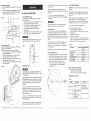
Fig. A
properly secured.
USE ONLY THE RECOMMENDED
ACCESSORIES.
Use extra caution with very large, very small, or
awkward workpieces.
Keep hands away from the blade at all times to
prevent accidental injury.
Do not remove jammed cutoff pieces until the blade
has stopped.
Maintain proper adjustment of blade tension, blade
guides, and thrust bearings.
Adjust upper guide to just clear the workpiece.
Hold the workpiece firmly against the table.
Grounding Prong
Properly Grounded
3-Prong
Fig. B
(_]/
__
.._¢_----_-_"
//,i<Y_-
GUIDELINES
13. SUPPORT round work properly (with a V-block or
clamped to the miter gauge) to prevent it from rolling
and the blade from biting.
_!ill
SAVE THESE
J
is Connected to a
_._¢_p
! i]_" _
Known Ground
't_l _
L----._-" IF" 2-Prong
_
.N. '-_-"--_. Receptacle
Adapter
FOR EXTENSION
CORDS
USE PROPER EXTENSION CORD. Make sure-your
extehsion cord is in goed condition. When using an
extension cord, be su[_ ts use one heavy enough to carry
the current your produc'_will draw. An undersized cord will
result in a drop in line voltage and in loss of power which will
cause the too! to overheat. The table below shows the
correct size to use depending on cord length and nameplate
ampere rating. If in doubt, use the next heavier gauge. The
smaller the gauge number, the heavier the cord.
Use a separate electrical circuit for your tools. This circuit
must not be less than #12 wire and should be protected with
a 15 Amp time lag fuse. Before connecting the motor to the
power line, make sure the switch is in the OFF position and
the electric current is rated the same as the current stamped
on the motor nameplate. Running at a lower voltage will
damage the motor.
12. SMALL PIECES should be secured with jigs or fixtures.
Do not hand hold pieces that are so small your fingers
are under the blade guard.
Make sure This
This band saw is for indoor use only. Do not expose to rain
or use in damp Ioc:ations.
USE ONLY 3-wire extension cords that have 3-prong
grounding plugs and 3-pole receptacles that accept the
tool's plug. Repair or replace damaged or worn cord
immediately.
11. PLAN intricate and small work carefully to avoid
pinching the blade. Avoid awkward operation and hand
positions to prevent accidental contact with the blade,
_1
_.,_--_f-:_...
IMPROPER CONNECTION of the equipment grounding
conductor can result in risk of electric shock, The conductor
with the green insulation (with or without yellow stripes) is
the equipment grounding conductor. If repair or replacement
of the electric cord or plug is necessary, DO NOT connect
the equipment grounding conductor to a live terminal.
10. WORKPIECES must be secured so they don't twist,
rock, or slip while being cut.
Receptacle
Grounding Lug ____.._
DO NOT MODIFYTHE PLUG PROVIDED. If it will not fit the
receptacle, have the proper receptacle installed by a
qualified electrician.
CHECK with a qualified electrician or service person if you
do not completely understand the grounding instructions, or
if you are not sure the tool is properly grounded.
INSTRUCTmONS
3-Prong Plug
IN THE EVENT OF A MALFUNCTION OR BREAKDOWN,
grounding provides a path of least resistance for electric
current and reduces the risk of electric shock. This tool is
equipped with an electric cord that h_s an equipment
grounding conductor and a grounding plug. The plug MUST
be plugged into a matching receptacle that is properly
installed and grounded in accordance with ALL local codes
and ordinances.
USE EXTRA SUPPORTS to prevent workpieces from
sliding off the table top. Never use another person in
place of a table extension, or to provide additional
support for the workpiece.
SAVE THESE
CAUTION: In all cases, make certain the receptacle is
properly grounded. If you are not sure have a qualified
electrician check the receptacle.
This tool must be grounded while in use to protect the
operator from electrical shock.
For your own safety, read the entire instruction manual
before operating the band saw.
1. Wear eye protection.
2. Do not wear gloves, necktie, or loose clothing.
3. Make sure the saw is on a firm level surface and
5.
This tool is intended for use on a circuit that has a
receptacle like the one illustrated in FIGURE A. FIGURE A
shows a 3-prong electrical plug and receptacle that has a
grounding conductor, tf a properly grounded receptacle is
not available, an adapter (FIGURE B) can be used to
temporarily connect this plug to a 2-contact ungrounded
receptacle. The adapter (FIGURE B) has a rigid lug
extending from it that MUST be connected to a permanent
earth ground, such as a properly grounded receptacle box.
THE TEMPORARY ADAPTER SHOULD BE USED ONLY
UNTIL A PROPER GROUNDED OUTLET CAN BE
INSTALLED BY A QUALIFIED ELECTRICIAN. The
Canadian Electrical Code prohibits the use of adapters.
POWER SUPPLY AND MOTOR SPECIFICATIONS
15.ALWAYS
WATCHthesawrunbeforeeachuse.Ifthere
isexcessive
vibration
orunusual
noise,stopimmediately.
Turnthesawoff.Unplugitimmediately.
Donotstartthe
sawagainuntiltheproblemhasbeenlocatedand
corrected.
4.
REQUIREMENTS
NSTRUCT ONS
5
Be sure your extension cord is properly wired and in
good condition. Always replace a damaged extension cord or
have it repaired by a qualified person before using it. Protect
your extension cords from sharp objects, excessive heat and
damp or wet areas.
Rating
Totallength
100'
150'
16
16
14
18
16
14
12
12
t6
16
14
12
16
14
12
Notrecommended
not more th;_n
0
6
6
10
10
12
25'
ofcordinfeet
50'
more qhan
i18
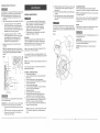
UNPACKING
CONTENTS
SAVE THESE iNSTRUCTiONS
o
o
•
To avoid injury from unexpected starting, do not plug the
power cord into a power source receptacle during
unpacking and assembly. This cord must remain
unplugged whenever you are assembling or adjusting
the saw.
Although compact, this saw is heavy. To avoid back
injury, get help whenever you have to lift the saw.
If any part is missing or damaged, do not plug the band
saw in until the missing or damaged part is replaced,
and assembly is complete.
TABLE
RECOMMENDED
ACCESSORIES
Visit your Sears Hardware Department or see the Sears
Power and Hand Tool Catalog to purchase recommended
accessories for this power tool.
To avoid personal injury:
•
Use only accessories recommended for this band saw.
o
Follow instructions that accompany accessories. Use of
improper accessories may cause hazards.
Use only accessories designed for this band saw to
avoid injury from thrown broken parts or workpieces.
Do not use any accessory unless you have completely
read the instruction or owner's manual for that accessory.
ITEM
Miter gauge
Blade width: 1/8", 1/4", 3/8",1/2"
Blade length: 80"
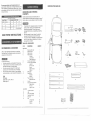
AND CHECKING
Carefully unpack the band saw and all its parts, and
compare against the list below and the illustration on page 7.
Place the saw on a secure surface and examine it carefully.
(when using 120 volts only)
Ampere
UNPACKING YOUR BAND SAW
OF LOOSE
DESCRIPTION
BAND SAW
A
B.
C.
D.
Band
Table
Table
Table
G.
H.
I.
J.
K.
LEG STAND
L.
M.
N.
O.
R
Q.
C
D
E
F
G
PARTS
ITEM
E.
F.
B
QUANTITY
saw with motor
with insert
trunnions
hardware
Hex bolts
Lock washers
Table alignment pin
Trunnion support bracket
Trunnion support hardware
Long bolt
Short hex. bolt
Hex nut
Table lock knobs
Washers
Miter gauge
Sawdust port
Hex bolts
Washers
Power cord hooks
Phillips head bolts
Hex. key
Stand attachment hardware
Large washers
Hex. nuts
Long hex. bolts
1
1
2
Leg stand top plate
Legs
Short lower brackets
Long lower brackets
Foot pads
Bag:
Carriage bolts
Hex. nuls
1
4
2
2
4
Washers
6
6
1
!
2
1
1
2
2
1
1
2
2
2
2
1
8
4
4
32
32
32
H
I
J
A
K
I oo
°o
1
f °°
°°
1
I
I°°
°o
°°
I
1
M
L
F,
°
,°!
°
N
O
P
CRAFTSMAN
Blade tension knob
Lower blade
support bearing
"blade wheel
guard
Lower blade
guide
3er blade
support bearing
Upper blade
guide
Table insert
Miter gauge
Table aligning pin
Upper cover
--
ON/OFF switch
BLADE GUIDES - Support the blade and keep it from
twisting during operation. Blade guides must be adjusted
when the blade is changed or replaced.
KERF - The material removed by a blade in a through cut,
or the slot produced by the blade in a nomthrough or partial
cut.
LEADING EDGE - The end of the workpiece pushed into
the cutting tool first.
BLADE TENSION KNOB - Controls the amount of blade
tension when changing blades.
MITER CUT - An angle cut made across the width of a
workpiece.
BLADE TRACKING KNOB - Adjusts the blade position so
the blade always runs in the center of the wheel.
RELIEF CUT - Removal of waste material by a cut from the
outside edge, allowing easier cutting of intricate curves.
ON / OFF SWITCH - Has a built-in child safety lock. To lock
the switch in the OFF position, remove the switch key from
the switch.
RESAW - A cutting operation to reduce the thickness of the
workpiece to make thinner workpieces.
RESIN - A sticky sap that has hardened.
bevel scale
Table removed for clarity
of illustration
RELIEF CUT - Removal of waste material by a cut from the
outside edge, allowing easier cutting of intricate curves.
Lower blade
wheel
Lower cover
SAWDUST PORT - Helps keep the machine free from
sawdust. The sawdust port makes an excellent hookup for a
wet/dry vacuum.
V-Belt
Blade tension
gauge
TABLE LOCK KNOB - Locks the table in place.
Upper blade
guide red
Mounting holes
Upper blade
guide lock knob
Motor
BAND SAW TERMS
TILT (BEVEL) SCALE - Shows the degree the table is tilted
for bevel cutting.
ilade tracking
knob
RIPPING CUT - A cutting operation along the length of the
workpiece.
R.P.M. - Revolutions per minute. The number of turns
completed by a spinning object in one minute:
SAW BLADE PATH - The area of the workpiece or table top
directly in line with the travel of the blade or the part of the
workpiece which wilt be cut.
SET -The distance between two tips of the saw blade teeth,
bent outward in opposite directions to each other.
UPPER BLADE GUIDE LOCK KNOB - Locks the upper
slide. Use it after you adjust the upper guide assembly to
make sure the upper blade guide just clears the workpiece
before cutting. Upper guide lock knob must be tightened
before the band saw is turned on.
TRAILING END - The workpiece end last cut by the blade.
Table lock plate
WOODWORKING
WORKTABLE - The surface on which the workpiece rests
while performing a cutting or sanding operation.
Sawdust port
BEVEL CUT - An angle cut made through the face of a
workpiece
Power
cord wrap
pulley
Blade
Miter slot
Table
Table trunnion
V-belt
tension lock
TERMS
WORKPIECE - The item being cut. The surfaces of a
workpiece are commonly referred to as faces, ends, edges.
Motor
COMPOUND CUT - A simultaneous bevel and miter cut.
Stand top table
CROSSCUT - A cut made across the width of the
Leading Edge
Kerr
Relief cu_
Sawblade Path
workpiece.
Leg stan d
RRM. - Feet per minute. Used in reference to the surface
speed of the saw blade.
FREEHAND - Performing a cut without using a fence
(guide), hold-down or other proper device to prevent the
werkpiece from twisting during the cutting operation.
Surface
Workpiece
Trailing Edge
GUM - A sticky sap based residue from wood products.
_i!ii!i
HEEL - Misatignment of the blade.
FIG. E
FIG. C
"---"
12
3
1
ASSEMBLY
iNSTRUCTiONS
TOOLS NEEDED
.
Although compact, this saw is heavy. To avoid back injury, get
help to lift the saw.
v("
_
_Ipl,l,l,l,_
Phillips
screwdriver
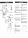
ASSEMBLE BAND SAWTO LEG STAND (FIG. B)
1. Lift the saw body (1) and place on the leg stand (2),
aligning the mounting holes (3) of the saw base with the
four mounting holes of the leg stand top plate.
2. Attach the band saw to the stand with four long hex head
bolts (4) and four flat washers (5).
3. Place a flat washer (5) and hex nut (6) on each bolt from
the underside. Hand tighten.
4. Tighten all mounting bolts and nuts with a wrench.
5. Tighten all leg stand bolts and nuts with the wrench.
Combinationsquare
_l_j41'l_l'l'('l
' Adjustable wrench
'
I'1'
Straight edge
_)
Feeler gauge - size 0.02
ASSEMBLE THE BAND SAW TABLE (FIG. D, E, F, G)
Mounting the trunnion support bracket (FIG. D)
1. Remove the two hex head bolts (1) and washers (2),
located on the lower band saw housing.
2. Place the trunnion support bracket (3) on the saw body,
as shown, aligning the mounting holes.
3. Place the washers on the hex head bolts, and insert into
the threaded holes, through the bracket and saw body.
Tighten.
4. Thread a nut (4) onto the table stop bolt (5) and screw
both into the rear tab (6) on the trunnion support bracket.
5. Tighten the nut down onto the bracket tab.
FIG. B
For your safety, never connect plug to power source
receptacle until all assembly and adjustment steps are
completed, and you have read and understood the safety
and operating instructions.
LEG STAND ASSEMBLY (FIG. A)
1. Lay the top plate (1) upside down on a flat surface.
2. Attach a leg (2) to the outside of the stand top plate with
four carriage bolts (3), washers (4), and nuts (5). Do not
tighten.
3. Repeat for the remaining three legs.
4. Attach two long brackets (6) and two short brackets (7)
to the inside of the legs, using carriage bolts (3),
washers (4), and nuts (5). Do not tighten.
5. Place the leg pads (8) on each leg and turn the leg
stand upright on a firm level surface.
6. Adjust the stand for stability.
FIG. A
9. Turn the table right side up.
10. Remove the table insert (13) from the table.
11. Guide the table slot (14) over the saw blade and rotate a
1/4 turn, so the slot is perpendicular to the blade.
12. Placing the scale lock knob bolts (10) through the
trunnion bracket holes (15) as shown, lower the table
onto the trunnion bracket.
FIG. F
FIG. D
4•
5
•
1
6 _
2
15
'9
i
,
11
3
1
13. Place a lock knob (16) on each scale knob bolt. Adjust
the table by aligning the zero scale mark to the scale
pointer (17), and tighten the knobs.
14. Replace the table insert (13), aligning the indents.
15. Place the table aligning pin (18) in the hoie at the front of
the table, and tighten.
FIG. G
THE SAWDUST
PORT (FIG. C)
i
The sawdust port has a 2-1/2"(O.D)/2-1/4"(I.D) diameter opening, suitable for attaching to a wet / dry vacuum hose, to help
keep the work area free of sawdust.
, '"',_
!.
2.
3.
_,.....
....
...."_
4.
8
10
Remove the bolts (1) and washers (2) from the sawdust
port (3).
Open the lower wheel cover (4).
Attach the sawdust port to the edge of the wheel cover,
using the same hex. head bolts and washers.
Tighten the bolts and close the cover.
i
i
:J
Mounting the table (FIG. E, F, G)
6. On the underside of the table (7), place the scale
brackets (8) on the bracket mounting holes (9).
7. Be sure the long lock knob bolts (10) are placed
upwards through the bracket slots as shown.
8. Place lock washers (11) on three short hex head
bolts (12). Thread the bolts through the mounting holes
and tighten.
13
18
INSTALLING AND REMOVING BLADES (FIG. H)
Installing
1. Make sure the blade tensior knob (1) is turned
counterclockwise until it stops.
2. Remove o_eblade as explained in "Removing"
3. Guide the new blade (7) through the table slot (11).
Make sure the blade teeth are pointing forward and
down.
To avoid injury from accidental starting, always turn the
switch OFF and remove the plug from the power source
before moving, replacing, or adjusting the blade.
Removing
1. Loosen the blade tension by turning the blade tension
knob (1) counterclockwise.
2. Remove the table insert (2) and remove the table
aligning pin (3) from the table.
3. Open the upper and lower wheel cover doors (4).
4. Loosen the two Phillips screws (5) and remove the upper
blade guard (6).
5. Remove the blade (7) from the upper and lower blade
guides (8).
6. Carefully pull the blade from the side slot (9) and from
the wheels (10).
7. Swing the left side of the blade toward you, turning the
blade so it wilt fit through the slot (11) in the table, and
remove.
INSTALL POWER CORD BRACKETS (FIG. J)
1. Power cord brackets (1) are provided for convenient
cord storage. Attach the power cord brackets to the back
of the saw body, as shown, with two Phillips head
screws (2). Tighten.
2. Wrap the power cord onto the brackets when the band
saw is'not in use, to prevent damage to the cord.
NOTE: To avoid lifting the workpiece, lhe blade teeth
must point aownwara toward the table.
4.
5.
6.
7.
8.
9.
FIG. J
Swinging the left side off the blade away and back. place
the blade on the upper and lower wheels (10).
Place the blade carefully between the upper and lower
blade gulaes (8).
Slide the blade into the slot (9) at the left of the wheels•
and maKe sure the blade is positioned at the rniddle of
the wheels.
Turning the blade tension knob (1) clockwise, tighten the
tension until the blade is tignt on the wheels.
Replace the table insert (2) and the table aligning a_n (3).
Adjust the utade tracking and tension properly (See
ADJUSTMENT INSTRUCTIONS sectlont before
operating the band saw.
FIG. H
_ Fy ""_
FIG. L
ADJUSTMENT
To avoid injury, the blade tension, tracking, and upper ana
lower guides and bearings must be properly adjusted before
operating the band saw. (See ADJUSTMENT
INSTRUCTIONS section)
10
MITER GAUGE (FIG. I)
A miter gauge (1) is supplied with your band saw to be used
in the table slot (2) on the right side of the blade. The miter
gauge can be tilted 0 ° to 45 ° right or left, to maintain an
accurate angle for your workpiece. A bracket is provided on
the leg stand for convenient miter gauge storage.
6
5
3
INSTRUCTIONS
6
To avoid injury, turn the switch OFF and unplug the band saw
from the power source before making any adjustments.
TABLE ADJUSTMENTS
(FIG. K, L)
Tilting the table (FIG. K)
The band saw table (1) tilts 0 ° to 45 ° to the right
1.
2.
3.
2
Adjusting the 90 ° table stop (FIG. L)
1. Loosen the table lock knobs (2) and tilt the table to
the right.
2. Loosen the nut (4) on the table stop bolt (5) and lower
the stop bolt as far as possible.
3. Tilt the table until it rests on the stop bolt.
4. Place a combination square (6) on the table with the
heel of the square against the saw blade.
5. Adjust the tilt of the table left or r ght unt it is 90 ° to the
blade. Make sure there is no space between the square
and the blade. Tighten the table lock knobs.
6. Adjust the table stop bolt up until it touches the table.
Tighten the jam nut down to the support bracket.
7. Loosen the lock knobs and see that the table is resting
on the stop bolt.
8. Check the square to make sure the table is still square to
the blade. If not, readjust the stop bolt.
9. When the adjustment is accurate at 90 °, align the
pointer (7) to 0 ° on the scale (8).
Loosen both table lock knobs (2) underneath the table.
Tilt the table to the desired angle on the scale (3)
underneath the table.
Tighten the two table lock knobs.
2
10
8
0
4
10
I
1
7
FIG. K
FIG. I
1
3
3
I
8
I0
Before operation always make sure the blade is in center
of table insert slot.
. :...i".:: •
_i. -•
.:_
.":
_
••12_:'_
_
:i_:_
..•:
-:
".•:.:_Y-.
:
_
....
......
¸(i!ii:!ii i:iii!!
?:?!?ii¸¸:'! ¸¸¸¸¸¸:'
:
If the blade moves toward the front of the wheel, turn the
tracking knob (5) on the rear of the band saw clockwise.
This tilts the top of the wheel and moves the blade
toward the center.
If the blade moves toward the back edge, turn the
tracking knob counterclockwise, moving the blade toward
the center.
BLADE TENSION (FIG. M)
To avoid injury, turn the switch OFF and disconnect the saw
from the power source before rnaking any adjustments,
NEVER make tension adjustments with the machine running.
The gauge (1) on the bracket (2) at the rear of the upper
wheel housing indicates the proper tension for the various
blade widths.
1.
2.
3.
UPPER BLADE GUIDES AND BLADE SUPPORT
BEARING (FIG. P, Q)
o
NO'rE: Turn the tracking knob SLIGHTLY to make blade
tracking adjustments.
Set the blade tension gauge to correspond with the width
of the blade in use.
Turn the blade tension knob (3) clockwise, raising the
upper wheel to tighten the blade. Turn the knob
counterclockwise to lower the upper wheel, loosening
the blade.
As you become familiar with the saw, you may want to
change the tension settings.
The blade guard has been removed for clarity of
illustration. To avoid injury never operate the band saw
without all guards in place and in working order.
To avoid injury, turn the switch OFF and disconnect the
saw from the power source before making any
adjustments. NEVER make adjustments with the
machine running.
NOTE: Make sure the blade is tensioned and tracking
properly. Adjust the blade guides and support bearing after
each blade tension and Iracking adjustment. When the upper
blade guides and supporl bearings are adjusted, the lower
guides and bearings should also be adjusted.
5
NOTE: Changes in blade width and type of material
being cut will have an effect on the blade tension. Too
much or too little tension could break the blade. When
the band saw is not in use, relax the blade tension.
Blade guides (HG. P)
!. Make sure the blade is tensioned and tracking properly.
2. Loosen the front hex socket screws (1) with a hex wrench.
3. Move the guides (2) as close to the blade (3) as possible
without pinching it.
:
4. Using a feeler gaugel make sure the space between
each guide and the blade measures 0.02!' (the thickness
of a dollar bill)
........
5.
Tighten the hex socket screws:
6. Loosen the:side hex socket screw (4)by turning
counterclockwise,
::
7. Move the blade guide: bracket shaft (5) in or out until the
guide s are at least 1/3Z' behind the blade teeth.
8; The guides must remain behind the blade teeth during
operation to prevent damage to the saw blade.
9. Tighten the hex socket screw.
4
F_G. M
UPPER BLADE GUBDE ASSEMBLY (FIG. O)
To avoid injury, turn the switch OFF and disconnect the saw
from the power source before making any adjustments.
NEVER make adjustments with the machine running.
1.
2.
(FIG, N)
LOWER BLADE GUIDES AND SUPPORT BEARING
To avoid injury, turn the switch OFF and disconnect the saw
from the power source before making any adjustments.
NEVER make adjustments with the machine running.
NOTE: Make sure the blade is tensioned and tracking
properly.
The lower blade guides and support bearings should always
be adjusted after the blade is tensioned, the tracking is
adjusted, and the upper blade guides and upper support
bearings are properly adjusted.
Blade guides (FIG. R)
1. Loosen both front hex socket screws (1) with a hex
wrench.
FIG. P
BLADE TRACKING
FIG. O
2.
Move the guides (2) as close to the sides of the blade (3)
as possible without pinching it.
3. Using the feeler gauge, measure the spaces between
the guides and the blade. Adjust to 0.02".
4. Tighten the hex screws.
5. _ Loosen the side hex socket screw (4). Move the guide
suppod bracket (5) in or out until the guides are at least
1/32" behind the saw teeth. Tighten the screw.
Loosen the lock knob (1) and move the blade guide
assembly (2) up or down to 1/8" above the workpiece.
Tighten the lock knob.
FiG. O
4
F_G, R
2
5
To avoid injury, turn the switch OFF and disconnect the saw
from the power source before making any adjustments.
NEVER make tension adjustments with the machine running.
1.
2.
3.
4.
The blade (1) must be tensioned properly before
adjusting the tracking.
Open the upper cover.
Move the blade guides (2) and support bearings (3)
away from the blade, if necessary. See page 15 for
bearing and guide adjustment.
Rotate the wheel (4) slowly forward by hand, and check
the position of the blade on the wheel. The blade should
remain centered on the wheel as it turns.
....
0 ; 0:
! i;_ iO:i_
?
1
3
_'L_
Support bearing (FIG, Q)
10. Loosen the bearing hex socket screw (6).
11, Move the support bearing shaft (7:)in or out, until the
bearing (8) is 1/64" behind the blade.
12. Tighten the hex socket screw (6).
J
i: ¸:i; i ;£{i!:;:ill ;;ii _i!i¸iii!i¸¸I;I{
_i:i¸¸i i 'i¸iii¸_i
!_;:
iiiiiii:;il
14 il;ii
_!!!i
¸¸if:
¸i_!
_i:i!ii
i!i¸ii:;_:
_};:iil
¸i_i_i
i!li¸¸
i;ii!!i
¸:!!i
i_i!i:!
¸¸ii!_iiIJi
iiiil¸:il_iii!iii!i;il
¸I!
¸iilil
¸ii!i!!!ii!iiiii!:!iiiSiii_!
_!iiii!iiiii!i!
_:iiiii!i!:!ili!iii:ii_iiiiiiii!_i!!ii!!iii:_!ili
i!!i!iiii!iii!iiii!:iii!!!iiiii
_iliiii!i!iiii!i:ii:ii!i
¸!ii'iiii:i
¸i!!ii!ii:iiiiiiiii:i
¸!!il
¸¸!ii!
NOTE: The blade support bearing prevents the blade
from moving back too far and damaging the saw teeth
setting.
!
iI
2
I
5-4--
4
To avoid twisting the blade, do not turn sharp corners, saw
around corners.
Support bearing (FIG. S)
6. Loosen the bearing hex socket screw (7) with the hex
wrench.
7. Move the blade support bearing shaft (8) in or out until
the support bearing (9) is 1/64" behind the saw blade.
8. Tighten the bearing hex socket screw.
ON / OFF SWITCH (FIG. U)
The keyed switch is intended to prevent unauthorized
use of the band saw.
1. To turn the band saw ON insert the yellow key (1) into
the key slot (2) in the center of the switch.
2. Push the key firmly into the slot, then push switch
to the ON position to start the band saw.
3. To turn the band saw OFF push the switch to the
down position.
4. Remove the yellow switch key, when the saw has come
to a complete stop, by gently pulling it outward.
9
8
Remove the switch key whenever the saw is not in use.
Place it in a safe place and out of reach of children.
Pulley alignment (FIG.T)
The pulley alignment is adjusted properly at the factory and
should not need readjustment.
If adjustment is needed, or the belt needs replacing:
1. Place a straight edge in the front groove of both pulleys,
behind the blade wheel
2. Turn the hex socket screw (1) in the side of the motor
pulley (2) to loosen the pulley on the shaft.
3. Adjust the motor pulley in or out on the motor shaft (3)
to align the edges of the two pulleys.
4. When aligned, tighten the hex socket screw on the side
of the motor pulley.
CAUTION: Blade teeth are sharp. Use care when handling a
saw blade.
A band saw is basically a "curve-cutting" saw. It is not
capable of doing intricate inside cutting as can be done with
a scroll saw.
BASIC SAW OPERATIONS
FIG. S
BLADE SELECTION (FIG. W)
FIG. U
For longest wear and best cutting results, use the correct
blade thickness, width, and temper for the type of material
you will cut.
It is also used for straight line operations such as
crosscutting, ripping, mitering, beveling, compound cutting,
and resawing.
When sawing small curves and delicate work, use narrow
blades. Otherwise, use the widest blade possible,
For cutting wood and similar materials with this bandsaw,
purchase blades in widths up to 1/2", and a length of 80".
To avoid blade breakage, fire or other damage or injury,
NEVER use this band saw to cut ferrous metals.
Do not cut ferrous metals with this band saw.
Common causes of blade breakage:
•
Poor guide alignment and adjustment.
o
Forcing or twisting a wide blade around a short radius.
•
Feeding too fast.
Dull teeth or not enough set.
Too much blade tension.
CUTTING CURVES
When cutting curves, carefully turn the workpiece so the
blade follows without twisting. If the curve is so sharp that
you repeatedly back up and cut new kerr, use a narrower
blade, or a blade with more set (teeth further apart). When a
blade has more set, the workpiece turns easier but the cut is
rougher.
o
-
When changing a cut, do not withdraw the workpiece from
the blade. The blade may get drawn off the wheels. To
change a cut, turn the workpiece and saw out through the
scrap material area.
Setting top guide assembly too high .above the workpiece.
Lumpy or improperly finished braze or weld on the blade.
Continuous running of blade when not cutting.
FIG. W
Recommended Blade Width
(Inches)
Operation
When cutting long curves, make relief cuts as you go along.
l
ON
GENERAL CUTTING
FIG. T
Cross Cutting
Mitering
Beveling
Compound Cutting
Circle Cutting
Curve Cutting
CIRCLE CUTTING (FIG. V)
1. Adjust the guide assembly to 1/8" above the workpiece.
2. Use both hands while feeding the work into the blade.
Hold the workpiece firmly against the table. Use gentle
pressure. Do not force the work, ALLOW the blade to cut.
3. The smallest diameter circle that can be cut is
determined by the width of the blade. For example,
a 1/4" wide blade will cut a minimum diameter of
approximately 1-1/2".
BLADE SPEED SELECTION (FIG. X)
This band saw has two speed settings:
1. 2600 RRM. for normal operation.
2. 1410 RRM. for operation requiring more control.
FIG. V
For your safety, read and understand all GENERAL and
SPECIFIC SAFETY INSTRUCTIONS on pages 3 - 5 before
using the band saw.
Operating band saws involves a certain amount of hazard.
Before attempting regular work, use scrap lumber to check
the settings, and to get the feel of operating the band saw.
Read instructions and plan your work before cutting a
workpiece.
RECOMMENDED
2-1/Z'D
Minimum
Circle Diameter
1/2"
Blade Width
SPEED
APPLICATION
1. Basic wood cutting
2600 KRM. 2. Resawing
BLADETYPE
1.Skip tooth type
2. Hook tooth type
3. Regular tooth blades
1. Intricate wood cutting
2. Veneers, tiles,
plastics
1410 RRM.
15 teeth per inch blades
3. Nonferrous metals;
brass, copper,
aluminum
Do not force the workpiece, against the blade. Light contact
permits easier cutting and prevents unwanted friction and
heating of the blade.
Sharp saw biades need little pressure for cutting. Steadily
move the workpiece against the blade without forcing it.
:
SPEEDS
FIG. X
Do not turn the power ON until after you have made all
adjustments, checked that the guard is in place, and turned
the wheel by hand to make sure all parts work properly.
Always keep the guide assembly close to your work, 1/8"
above the workpiece.
16
1/4, 3/8, 1/2
1/4, 3/8, 1/2
1/4, 3/8, 1/2
1/4, 3/8, 1/2
See Fig. V
1/8, 1/4
17
CHANGING SPEED SE'I-FING (FIG.Y)
To avoid injury, turn the switch OFF and disconnect the saw
from the power source before making any adjustments.
NEVER make adjustments with the machine running.
1. Loosen the belt tension by turning the tension lock
handle (6).
2. Open the lower wheel cover and reposition the V-belt (3).
A.
B.
3.
Changing the speed from 1410 to 2600 FPM:
Remove the belt (3) from the band saw pulley (4)
first, and reposition in the saw pulley groove (1).
Next, remove the belt from the motor pulley (5) and
reposition in the motor pulley groove (1).
Changing the speed from 2600 to 1410 FPM:
Remove the belt (3) from the motor pulley (5) first,
and reposition in the motor pulley groove (2).
Remove the belt from the saw pulley (4) and
reposition in the saw pulley groove (2).
Tighten the belt tension by turning the tension lock
handle (6).
NOTE: After readjusting belt position and belt tension,
check and readjust the settings for the blade tension and
tracking, guides and bearings (See ADJUSTMENT
section).
GENERAL
.
,
,
MAINTENANCE
For your own safety, turn switch OFF and remove the
plug from power source receptacle before maintaining,
cleaning, adjusting, or lubricating your band saw.
To avoid fire or toxic reaction, never use gasoline,
naphtha, acetone, lacquer thinner or similar highly
volatile solvents to clean the band saw.
To avoid eye injury from blowing debris, wear safety
goggles when blowing out sawdust.
BAND SAW
Sawdust will accumulate under the table and base. This
could cause difficulty in the movement of the table when
setting up a band saw cut, and also cause a fire hazard.
Frequently blow out or vacuum up the sawdust.
Keep your band saw clean. Remove the sawdust from the
inside. Vacuum or blow out frequently.
Do not allow filth to build up on the table, the guides, or the
support bearings. Clean them with Craftsman Gum and Pitch
Remover.
NOTE: Do not immerse the support bearings in the gum and
pitch remover.
Put a thin coat of paste wax on the table so that the wood
slides easily while cutting.
--1
--4
5
3
5
MOTOR
1
2
To avoid possible injury or damage, NEVER use this band
saw to cut ferrous metals.
CAUTION: When cutting nonferrous metals, metal shavings
can react with wood dust and start a fire. To avoid this:
1. Disconnect any dust collecting hose from the band
SaW.
2.
3.
Remove all traces of wood dust from inside the saw.
Remove all metal shavings from inside the saw
before sawing wood again.
TO INSTALL A NEW BELT (FIG. Z)
1. Open the lower wheel door.
2. Loosen the blade tension by turning the blade tension
lock knob (!).
3. Remove the blade from the lower blade wheel
4. Loosen and remove the hex head bolt (2) and flange (3)
on the lower blade wheel.
5. Remove the lower blade wheel.
6. Turn the belt tension handle (4) on the rear of the saw
housing to loosen the v-belt tension.
7. Remove the v-belt (5).
8. Check the alignment of the two pulleys.
9. If the edges of the two pulleys are not aligned, see
"ALIGN THE PULLEYS" in ADJUSTMENT section.
!0. Place the new v-belt on the saw puiley and the motor
pulley. See OPERATION section "CHANGING SPEED
SETTINGS" on page for proper belt placement.
11. When positioned properly, tighten the v-belt tension by
turning the tension lock handle.
NOTE: The pulley belt is properly tensioned when there
is 1/2" deflection if pressed in the center between the
pulleys.
12 Replace the blade wheel. Push the wheel on firmly until
it is touching the saw pulley. Replace and tighten the
flange and nut.
13. Reinstall the blade (See iNSTALLING BLADES Section
on page ).
14. Adjust the blade tension, tracking, and the upper and
lower blade guides and bearings before operating the
band saw.
To avoid injury, the blade tension, tracking, and upper and
tower guides and bearings musl be properly adjusted before
operating the band saw. (See ADJUSTMENT INSTRUCTIONS
section)
FIG. Z
BLADE WHEEL TIRES
Pitch and sawdust that build up on the tires should be
removed with a stiff brush or scrape off with a piece of wood.
NOTE: To avoid damaging the tires do not use a sharp knife
or any kind of solvent.
When the tires become worn they should be replaced. When
replacing the tires, stretch them around the wheels but do
not glue them on.
MOTOR
Frequently blow or vacuum out any sawdust from the motor.
Follow lubrication instruction on the motor label.
To avoid electrocution or fire immediately replace a worn, cut
or damaged power cord.
'
LUBRICATION
All of the bearings ar# packed with grease at ti'_e.factory.
They require no further IL_brication.
CAUTION: Never put.lubric.ar_ts on the blade while it is
spinning.
MOTOR
TROUBLESHOOTING
,
+
GUIDE
To avoid injury from an accidental start, turn the switch OFF and always remove the plug from the power source
before making any adjustments.
All electrical or mechanical repairs should be done only by qualified service technicians• Contact the nearest
Sears Service Center.
Problem
Probable
Noisy operation.
1. Incorrect belt tension.
1. Adjust tension. See ASSEMBLY AND
ADJUSTMENTS section "INSTALL THE BELT".
2. Loose motor pulley.
3. Loose pulley cover.
2: Readjust and tighten motor pulley set screw.
3. Readjust and tighten pulley cover mounting
screws.
Motor will not start.
.
Cause
Remedy
Not plugged into power
outlet•
1. Plug it into the power outlet.
Switch and key not in ON
position.
. Motor cord cut or abraded.
4. Plug on cord is faulty.
5. Fuse on circuit breaks open.
6. Faulty motor
2. Insert key and turn the switch ON.
Too many electrical
machines.
2. Incorrect fuse.
1. Turn off other machines and try again.
.
GENERAL
Problem
Probable Cause
Blade does not run in the
center of the
upper wheel.
1. Not tracking properly.
2. Defective blade.
Remedy
1. Adjust tracking. See ASSEMBLY AND ADJUSTMENTS
section "BLADE TRACKING".
2. Replace blade.
Motor will not start and fuse
or circuit breaker opens.
Band saw slows down
when cutting.
1. Belt too loose•
2. Cutting too small a radius.
3. Dull blade.
4. Overloading motor.
Blades braking.
Blade dulls too quickly.
Band saw vibrates.
1. Too much tension on
the blade•
2. Kink in the blade caused by
cutting too small a radius or
turning the material too fast
when cutting.
1. Adjust belt tension. See ASSEMBLY AND
ADJUSTMENTS section "BLADE TENSION".
2. Stop feeding, back up the material slightly, until the
band saw speeds up.
3. Replace blade.
4. Slow down, you are trying to cut too fast. See
"MOTOR TROUBLESHOOTING GUIDE".
1. Adjust tension. See ASSEMBLY AND
ADJUSTMENTS section "BLADE TENSION"
2. Use correct cutting technique.
See OPERATION section "GENERAL CUTTING".
1. Blade guides set toe close to 1. Adjust upper and lower blade guides.
the teeth.
2. See OPERATION section "BLADE SELECTION".
2. Cutting incorrect material•
1. Too much tension on
motor belt.
.
3. Wheels do not rotate•
4. Undersized extension cord.
5. Short circuit.
3.
4.
5.
6.
Take to Sears Service Center for new cord.
Take to Sears Service Center for new plug.
Re-set; may be too many machines on line.
Take to Sears Service Center for repair
or replacement•
2. Try time delay fuse, or go to circuit with higher
rated fuse or circuit breaker.
3. Unplug and turn wheels by hand, move
obstruction.
4. Use correct size extension cord; see page 5.
5. Cord, plug, or motor need repair; take to Sears
Service Center for repair.
Motor fails to develop
full power.
1,
Low line voltage.
2. Faulty motor or capacitor.
1. Check power line for proper voltage.
2. Take to Sears Service Center for evaluation.
Motor overheats•
. Overload
on motor.
2. Poor ventilation of motor.
Provide better air circulation.
3.
Capacitor failure.
1. Reduce load to motor, feed work slower into blade•
2. Unplug and clean out around motor; provide
better air circulation.
3. Take to Sears Service Center for repair•
Motor stalls or slows•
1•
2.
3.
4.
1. Reduce load to motor, feed work slower into blade.
2. Check power line for proper voltage.
3. Take to Sears Service Center for repair.
4. Take to Sears Service Center for repair.
Frequent fuse or circuit
breaker failure.
1 • Motor overload.
2. Overload of electrical circuit.
3. Incorrect fuse or circuit
breaker.
1. Adjust according to ASSEMBLY AND
ADJUSTMENTS section, "INSTALL THE BELT".
Motor overload.
Low line voltage.
Loose wire connections•
Faulty motor.
21
1. Reduce load to motor, feed work slower into blade.
2. Too many electrical appliances on same circuit.
3. Have e ectrician upgrade service to outlet.
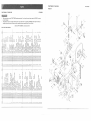
CRAFTSMAN
12" BAND SAW
137o224320
FIGURE A
CRAFTSMAN
12" BAND SAW
137.224320
+]2
I1
o
//
When servicing use only CRAFTSMAN replacement parts. Use of any other parts may create a HAZARD or cause
product damage•
Any attempt to repair or replace electrical parts on this band saw may create a HAZARD unless repair is done by a
qualified service technician. Repair service is available at your nearest Sears Service Center.
+
Order by PART NUMBER, not by key number
PARTS LIST FOR FIGURE A
° i
/
ci
o+
i+
2:
N i
i
i
i
o
76
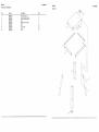
CRAFTSMAN
12" BAND
137.224320
SAW
CRAFTSMAN
12" BAND SAW
137.224320
FIGURE B
PARTS LIST FOR FIGURE B
121
I
].04
I
I
I
o
(
I
I
I
I
I
I
i ,t---
w
d i
86
_
O,"T"
z
G.. ;>
F-
bg
1
i 0
I04
_
(M
#.
I
I
I
o',lo
-_lCq
1
1
o
9
1
1
1
z
1.1.1_ u_
0,o
"rl_
117
.20
_,
Z
_zZ_Z_
GI
a__omz
r_
7_
_Ix
rr"
_ LU
. _
cc
j)
I
o,S
N
o0,_ o
N NI_
#.
I
I
O3
1
/1124¸
l9
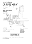
STAND
137.224320
PARTS LIST FOR FIGURE C
STAND
137.224320
FIGURE C
Key
Part No.
Description
1
2
3
4
5
6
7
8
9
10
3BS40101
3BS40201
3BS40301
3BS40401
3BS40501
3BS40601
3BS40701
3BS40801
3BS40901
3BS41001
Stand top plate
Lower bracket (long)
Lower bracket (short)
Leg
Miter gauge storage
Screw
Nut
Flat washer
Screw
Pad
Qty
1
2
2
4
1
2
32
32
32
4
1
o
J_
..4
q