1
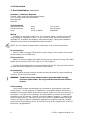
MS Series Pure Sine Wave Inverter / Charger Operators Manual IMPORTANT SAFETY INSTRUCTIONS This manual contains important safety instructions that must me followed during the installation and operation of this product. To reduce the risk of electrical shock, fire, or other safety hazard, the following safety symbols have been placed throughout this manual to indicate dangerous and important safety instructions. WARNING - Indicates a dangerous voltage or condition exists. CAUTION - Indicates a critical step necessary for the safe installation and operation of this device. NOTE - Indicates an important statement. Follow these instructions closely. ATTENTION - Electrostatic Sensitive Devices. Observe precautions for handling. All electrical work must be performed in accordance with local, state and federal electrical codes. Read all instructions and safety information contained in this manual before installing or using this product. This product is designed for indoor / compartment installation. It must not be exposed to rain, snow, moisture or liquids of any type. Use insulated tools to reduce the chance of electrical shock or accidental short circuits. Remove all jewelry such as rings, watches, bracelets, etc., when installing or performing maintenance on the inverter. Always disconnect the batteries or energy source prior to installing or performing maintenance on the inverter. Live power may be present at more than one point since an inverter utilizes both batteries and AC. Always verify proper wiring prior to starting the inverter. There are no user serviceable parts contained in this product. SAVE THESE INSTRUCTIONS 2004 - Magnum Energy, Inc. i IMPORTANT BATTERY SAFETY INSTRUCTIONS Wear eye protection such as safety glasses when working with batteries. Remove all jewelry such as rings, watches, bracelets, etc., when installing or performing maintenance on the inverter. Never work alone. Always have someone near you when working around batteries. Use proper lifting techniques when working with batteries. Never use old or untested batteries. Check each battery's label for age, type and date code to ensure all batteries are identical. Batteries are sensitive to changes in temperature. Always install batteries in a stable environment. Install batteries in a well ventilated area. Batteries can produce explosive gasses. For compartment or enclosure installations, always vent batteries to the outside. Provide at least one inch of air space between batteries to provide optimum cooling. Never smoke when in the vicinity of batteries. To prevent a spark at the battery and reduce the chance of explosion, always connect the cables to the batteries first. Then connect the cables to the inverter. Use insulated tools at all times. Always verify proper polarity and voltage before connecting the batteries to the inverter. To reduce the chance of fire or explosion, do not short-circuit the batteries. In the even of accidental exposure to battery acid, wash thoroughly with soap and water. In the even of exposure to the eyes, flood them for at least 15 minutes with running water and seek immediate medical attention. Recycle old batteries. SAVE THESE INSTRUCTIONS ii 2004 - Magnum Energy, Inc. Magnum Energy MS Series Inverter / Chargers Table of Contents Section Description 2. 1. 2. Installation Unpacking and Inspection Pre-Installation Locating the Inverter Locating Dedicated Batteries (optional) Hardware / Materials Required Tools Required Wiring AC Connections DC Connections AC Grounding DC Grounding Torque Requirements AC Main Panel Circuit Protection Wire Routing Installation Inverter Mounting Ventilation Requirements Battery Installation Battery Cables and Sizing DC Wiring DC Grounding Negative Cable Positive Cable Battery Wiring Parallel Connection Series Connection Series/Parallel Connection DC Fuse Block AC Wiring AC Input (Shore Power) Routing AC Input (Generator) Routing Main AC Electrical Panel Routing Wiring the Inverter AC Input Wiring the Inverter AC Output Final Inspection 1. 1. 2. 3. 4. 5. 6. 7. 3. Introduction Features and Benefits Standard Features How an Inverter/Charger Works Advantages of a Pure Sine Wave Inverter Appliances and Run Time The MS Series Inverter/Charger MS Series Neutral-to-Ground Safety System 2004 - Magnum Energy, Inc. Page 1 1 1 2 3 3 5 6 7 7 7 7 7 8 8 8 8 8 8 8 9 9 9 9 10 10 10 11 12 12 12 12 12 13 13 15 15 17 19 19 19 19 21 21 21 iii Table of Contents, continued Section Description 2. 4. Installation, continued Options Battery Temperature Sensor Installation and Wiring Remote Control Installation and Wiring AGS Module Smart Shunt Stacking Cable Kit Start-up and Test Connecting the Batteries to the Inverter Final Inspection and Power-up Configuring the Inverter 25 25 25 25 25 25 26 26 26 27 3. 1. Operation Operating the Inverter Search Inverter Mode AC Shore Power Mode Bulk Charge Mode Absorption Charge Mode Float Charge Mode Battery SaverTM Mode Fault or Alarm Conditions Low Battery High Battery Overload Overtemperature 28 29 29 29 29 29 29 29 29 31 31 31 31 31 4. 1. Troubleshooting Basic Troubleshooting 33 33 5. 1. 2. Preventive Maintenance Recommended Inverter and Battery Care Off-Season Storage 34 34 34 6. Specifications 35 7. Warranty 36 5. iv Page 2004 - Magnum Energy, Inc. 1. INTRODUCTION 1. Features and Benefits Congratulations on your purchase of the MS Series inverter/charger from Magnum Energy. The MS Series is a pure sine wave inverter designed especially for rugged mobile applications. Powerful, yet simple to use, the Magnum Energy inverter will provide you with years of trouble-free performance so you can enjoy the all of the comforts you have come to expect from your RV, boat, or truck, all backed by our limited 3 year (36-month warranty). The MS Series inverter is ETL Listed meeting the stringent requirements of UL458, ensuring you the highest level of electrical safety and reliability. Installation is easy. Simply connect the inverters output to your distribution circuits or electrical panel; connect your shore power cable (AC) to the inverters easy-to-reach terminal block; connect the batteries, and then switch on the power. Using the optional remote control, you can easily operate your inverter from anywhere within your motor coach. 2. • • • • • • • • • • • • • • • • Standard Features 2000, 2800 or 3600 Watt Models with 125 Amp Battery Charger Shelf, Bulkhead or Upside Down Mounting Pure Sine Wave Output Power Factor Corrected Charger (Sine Wave) RS485 Standard Remote Port Network Port Flash Programming ON/OFF Inverter-mounted Switch with LED Indicator 50 Amp Transfer (on Dual IN / Dual OUT Models) Extra Large AC Access Cover with Terminal Screw Block 360 degree DC Connection Terminals with Covers Battery Temperature Sensor - for optimum battery charging Aluminum Cover Smooth, Aesthetically Pleasing Design ETL listed to UL/cUL 458 The following accessories are also available for MS Series products: Remote Control - for convenient finger tip operation AGS Module - automatically starts and stops your generator Smart Shunt - provides precise DC voltage and current measurements Stacking Cable Kit - designed to accommodate dual inverter configurations 2004 - Magnum Energy, Inc. 1 1. INTRODUCTION 3. How an Inverter/Charger Works An inverter takes direct current (DC) from your batteries and turns it into alternating current (AC), exactly like you use at home. It also takes alternating current (when connected to shore power) and transforms it into direct current to recharge your batteries. There are two modes of operation associated with an inverter/charger: Inverter Mode: Direct current (DC) from the vehicles batteries is transformed into alternating current (AC) for use with you household electrical appliances. Charger Mode: Alternating current (AC) is taken directly from shore power (or other AC sources) and passed directly to your household appliances. At the same time, the incoming AC is also converted to DC to recharge the vehicles batteries. Figure 1 MS Series Inverter / Charger 2 2004 - Magnum Energy, Inc. 1. INTRODUCTION 4. Advantages of a Pure Sine Wave Inverter Todays inverters come in two basic output waveforms: modified sine (which is actually a modified square wave) and pure sine wave. Modified sine wave inverters approximate a pure sine waveform and will run most appliances and electronics without any problems. These inverters are less expensive and, therefore, offer a viable alternative to more expensive pure sine inverters. The output of a pure sine wave inverter is equal to or, in many cases, better than the grid power used in your home. Virtually any electronic device will operate from a pure sine wave inverter. Motors run cooler, microwaves usually cook faster and clocks keep better time just to name a few examples. Without compromising quality or performance, the MagnaSine provides you with all of the advantages of a pure sine wave inverter at a much lower cost than many on the market. The MagnaSine is built on the same platform as our popular ME Series modified sine wave inverters allowing for an easy upgrade from the original ME installation. This standard platform also helps reduce cost by using standard parts across many models. All Magnum accessories such as the Remote Controller, AGS (AutoGen Start), and network accessories are standard for all ME, RD and MS Series inverters. 5. Appliances and Run Time The MS Series inverter/charger can power a wide range of household appliances including small motors, hair dryers, clocks and other electrical devices. As with any appliance using batteries for power, there is a certain length of time that it can run this is called run time. Actual run time depends on several variables including the size and the type of appliance, the type of batteries installed in your mobile application, as well as the batterys capacity and age. Other factors such as the batterys state of charge and temperature can also affect the length of time your appliances can run. Appliances such as TVs, VCRs, stereos, computers, coffee pots, incandescent lights and toasters can all be successfully powered by your inverter. Larger electrical appliances, however, such as stoves, water heaters, etc., can quickly drain your batteries and are not recommended for this application. All electrical appliances are rated by the amount of power they consume. The rating is printed on the products nameplate label, usually located on its chassis near the AC power cord. Even though it is difficult to calculate exactly how long an inverter will run a particular appliance, the best advice is trial and error. Your MS Series inverter has a built-in safeguard that automatically protects your batteries from over discharge. NOTE: For optimum performance, a minimum battery bank of 200 AHr is recommended. Device Blender Computer Drill Hot Plate Light (Flo) Microwave Load 400 W 300 W 500 W 1800 W 10 W 1000 W Device Coffee Maker Color TV Hair Dryer Iron Light (Inc) Refridgerator Load 1200 W 150 W 1000 W 1000 W 100 W 500 W Table 1 - Typical Appliance Power Consumption 2004 - Magnum Energy, Inc. 3 1. INTRODUCTION Power ON/OFF Switch Charging / Inverting LED Stack Port Magnum Net Port Remote Port Battery Temp Sensor Port Figure 2 MS Series Inverter / Charger Switch, LED and Connection Ports DC Connections AC Connections Figure 3 MS Series Inverter / Charger Electrical Connection Points 4 2004 - Magnum Energy, Inc. 1. INTRODUCTION 6. The MS Series Inverter/Charger The MS Series inverter/charger is designed to allow easy access to wiring, circuit breakers, controls and LED status indicator. Its die cast baseplate with one piece aluminum cover ensures maximum durability with minimum weight, as well as cooler more efficient operation. The inverter is equipped with the following features: ON / OFF Switch - used to manually switch the inverter ON and OFF. Green LED Indicator • Medium flash (1 every 2 seconds) Indicates connected loads are being powered from the batteries (inverting). • Fast flash (1 per second) Indicates search mode, conserving power when appliances are switched OFF. • Solid Indicates bulk charge when the batteries are low and the inverter is connected to shore power. • Fast flash (1 per second) Indicates absorption charge when the batteries are almost fully recharged and the inverter is connected to shore power. • Slow flash (1 every 8 seconds) Indicates float charge when batteries are fully charged and the inverter is connected to shore power. • LED off Indicates a fault condition such as low battery, overload or over temperature. Remote Control Port - accepts connector for Magnum remote control cable. BTS Port - accepts connector for remote battery temperature sensor cable. MagnumNet Communication Port - accepts connector for Auto Gen Start or Smart Shunt (DC current display) cable. Positive Battery Terminal - provides 360 degree connection point for the positive (+) cable from the vehicles batteries. Negative Battery Terminal - provides 180 degree connection point for the negative (-) cable from the vehicles batteries. Chassis Ground Connector - accepts chassis ground cable. AC Access Cover - provides access to internal AC screw terminal connections. AC Input Circuit Breaker - protects main AC (shore power) input circuit. AC Output 1 Circuit Breaker (optional) - protects the primary AC output circuit (on dual out units only). AC Output 2 Circuit Breaker (optional) - protects secondary AC output circuit (on dual out units only). MS Series Nameplate Label - provides product and safety information. 2004 - Magnum Energy, Inc. 5 1. INTRODUCTION 7. MS Series Neutral-to-Ground Safety System All MS Series inverters employ an internal, neutral-to-ground safety feature, in accordance with applicable electrical codes for use in mobile applications. This design prevents an electrical shock hazard between the vehicles neutral and the shore powers neutral (when connecting the inverter to shore power). Internal Neutral-to-Ground Switching (Battery Inverter Mode) The AC output neutral is connected to the chassis ground by an internal relay when the inverter is operating from the batteries, thus creating a neutral to ground bond within the inverter. External Neutral-to-Ground Switching (AC Shore Power Mode) The inverters internal relay opens and removes the ground from the neutral conductor when the vehicle is connected to an external AC power source. The neutral is connected directly to the output neutral thus providing the neutral bond at the external AC source. WARNING: Do not attempt to disable the the neutral-to-ground safety feature. Figure 4 MS Series Inverter / Neutral-to-Ground Safety System 6 2004 - Magnum Energy, Inc. 2. INSTALLATION 1. Unpacking and Inspection Carefully remove the MS Series inverter from its shipping container and inspect all contents. If items appear to be missing or damaged, contact Magnum Energy at (425) 353-8833 or your authorized Magnum Energy dealer. If at all possible, retain the shipping container in the event the unit ever needs to be returned for factory service. ATTENTION: Electrostatic Sensitive Devices. Observe precautions for handling. 2. Pre-Installation Before installing the inverter, read all of the instructions and cautionary markings contained in this manual. NOTE: The inverter is heavy. Use proper lifting techniques during installation to prevent personal injury. Locating the Inverter The inverter must be mounted in a clean, dry, ventilated environment where the ambient temperatures will not exceed 122 ºF (50 ºC). The location must be fully accessible and protected from exposure to heat producing devices. You can mount the inverter horizontally, vertically or upside-down. It must be securely fastened to a shelf, bulkhead, or other structural part. Allow enough clearance to access the AC and DC connection points as well as the inverters controls and status indicator. As with any inverter, it should be located as close to the batteries as possible. Longer battery cable runs tend to loose efficiency and reduce the overall performance of an inverter. If you are planning to install dedicated batteries, other than the vehicles, make sure they are in a dedicated compartment that has ventilation to the outside. Also it is important that you never mount the inverter directly above the batteries as they emit corrosive fumes which could damage the inverters electronics. Locating Dedicated Batteries (optional) Dedicated batteries must be mounted in a clean, dry, ventilated environment where they are protected from high and low temperatures. The batteries must be mounted upright (if using liquid batteries) and securely fastened to the vehicle. The location must be fully accessible and protected from exposure to heat producing devices. To ensure optimum performance, a ventilated battery enclosure is recommended. The batteries should be located as close as possible to the inverter. Longer battery cable runs tend to loose efficiency and reduce the overall performance of an inverter. Also, do not mount the batteries beneath the inverter (or in the same compartment). Batteries emit corrosive fumes which could damage the inverters electronics. NOTE: For optimum performance, Magnum Energy recommends using AGM (absorbed glass mat) batteries such as LifelineTM brand batteries. CAUTION: Never locate dedicated batteries near the vehicles fuel tanks containing gasoline or propane. 2004 - Magnum Energy, Inc. 7 2. INSTALLATION 2. Pre-Installation, continued Hardware / Materials Required Conduit, strain-reliefs and appropriate fittings 1/4" mounting bolts and lock washers Electrical tape Wire ties Tools Required Misc screw drivers Drill and drill bits Level Level Pliers Pencil or Marker 1/2" wrench Wire strippers Multimeter Wiring Pre-plan the wire and conduit runs. For maximum safety, run both AC and DC wires/cabling in (separate) conduit. Direct current wiring, due to its potential to generate RFI, should be tied together with electrical tape. Wiring and installation methods must conform to all applicable electrical codes. NOTE: Run DC cabling in twisted pairs, keeping the runs as short as practical. AC Connections Use #10 AWG (or larger) THHN wire for all AC wiring. The inverters AC terminal blocks accept up to #6 AWG wire. DC Connections Battery to inverter cabling should be only as long as required. If using #2/0 AWG cables, do not exceed 5 feet (one way) for 12 VDC systems. Crimped and sealed copper ring terminal lugs with a 5/16 hole should be used to connect the battery cables to the inverters DC terminals. AC Grounding The MS Series inverter/charger contains an internal neutral-to-ground switching circuit for the AC electrical system. WARNING: The AC shore power neutral must be grounded ONLY through the shore power cable. Do not ground AC neutral to the vehicles chassis. DC Grounding The inverter/charger should always be connected to a permanent, grounded wiring system. For the majority of installations, the negative battery conductor is bonded to the vehicles safety-grounding conductor (green wire) at only one point in the system. The size for the conductor is usually based on the size of the largest conductor in the DC system. DO NOT connect the battery negative (-) cable to the vehicles safety ground. Connect it only to the inverters negative battery terminal. If there are any non-factory installed DC appliances on board the vehicle, DO NOT ground them at the safety ground. Ground them only at the negative bus of the DC load center (as applicable). 8 2004 - Magnum Energy, Inc. 2. INSTALLATION 2. Pre-Installation, continued Torque Requirements Torque all AC wiring connections to 16 inch pounds. Torque DC cable connections to 10-12 foot pounds. AC Main Panel If the installation will be powering a wide-range of appliances throughout the vehicle, an AC main panel is often recommended. This is similar in appearance and function as your homes circuit breaker panel, providing an additional level of control and protection for the various circuits. Always refer to electrical codes for safe wiring practices. Circuit Protection If using a AC main panel for distribution, always use breakers that provide the correct ampere branch circuit protection in accordance with the National Electric Code. The breakers must be properly rated for the appliances being powered. NOTE: Both AC and DC disconnects / overcurrent protection must be provided as part of the installation. Recommended GFCI (Ground Fault Circuit Interruption) Breakers Shock SentryTM #XGF15V-SP Leviton Smart Lock #8899-A Hubbel #GF520EMBKA Wire Routing Determine all wire routes throughout the vehicle both to and from the inverter. Conductors that are at risk to physical damage must be protected by conduit, tape, or placed in a raceway. Conductors passing through walls, bulkheads or other structural members must be protected to minimize insulation damage such as chafing. During the installation, always avoid placing conductors near sources of chafing caused by vibration or constant rubbing. CAUTION: Always check for existing electrical, plumbing or other areas of potential damage prior to making cuts in structural surfaces, bulkheads or walls. Typical routing scenarios are: AC Input wiring from the shore power source to the inverter AC Input wiring from a generator (optional) to the inverter DC Input wiring from the batteries to the inverter AC Output wiring from the inverter to the coachs AC main panel or to dedicated circuits Battery Temperature Sensor cable from the inverter to the batteries Remote Control cable (optional) to the inverter Ground wiring from the inverter to an external vehicle ground 2004 - Magnum Energy, Inc. 9 2. INSTALLATION 3. Installation NOTE: Read all instructions and cautionary markings located at the beginning of this manual and in the pre-installation section, before installing the inverter and batteries. CAUTION: Do not mount the inverter or the batteries near the vehicles gasoline or propane fuel tanks. Provide adequate clearance and ventilation to the inverter Mount the inverter only on a noncombustible surfaces. Maximum abient temperature MUST NOT exceed 113 °F (45 °C). For Canadian installations, the inverters vents must face downward. Inverter Mounting Position the inverter in the designated mounting location: shelf, bulkhead or upside-down. Allow enough clearance to access the AC and DC connection points as well as the inverters controls and status indicator. Also allow for air flow in to and around the inverter, especially near the cooling fans (approximately 3). Mark the mounting holes in the base of the inverters chassis. Remove the inverter and drill pilot holes into the mounting surface. Secure the inverter to the mounting surface using appropriate screws and lock washers. Remove the inverters AC access panel in accommodate the AC Input and Output wiring and conduit. Ventilation Requirements In order to provide optimum performance, longer inverter life and reliability, and avoid "Overtemp" fault conditions," clearances around the inverter MUST be: Side and Back: 3 minimum - Front (with DC connections): 6" minimum If the inverter is mounted in an enclosed compartment, airflow must be at least 100 cfm in order to maintain no more than a 20 0C degree rise in compartment temperature. Minimum clearances can be reduced if airflow is increased, but in no case should clearance around inverter be less than 2" on all sides. If an "Overtemp" faults occur, reduce the load or increase ventilation to the inverter. Mounting Screw Placements 10 Figure 5 MS Series Inverter / Charger Base Plate 2004 - Magnum Energy, Inc. 2. INSTALLATION 3. Installation, continued Battery Installation NOTE: To ensure the best performance from your inverter system, do not use old or untested batteries. Batteries must be of the same size, type, rating and age. NOTE: For optimum performance, Magnum Energy recommends using AGM (absorbed glass mat) batteries such as LifelineTM brand batteries. NOTE: If using Flooded Lead Acid batteries, they must be mounted upright. CAUTION: Install batteries in a well ventilated area. Batteries can produce explosive gasses. For compartment or enclosure installations, always vent batteries to the outside. Place the batteries as close as practical to the inverter, preferably in an insulated and ventilated enclosure. Allow adequate space above the batteries (+/- 6 above the batteries) to access the terminals and vent caps (as applicable). Also allow at least 1 of space between the batteries to provide good air flow. DO NOT mount the batteries directly under the inverter. Secure the batteries to the mounting surface with battery hold down clamps. Inverter MS2012 MS2812 MS3624 DC Rating 200 amps 250 amps 300 amps @ 1 to 3 ft @ 3 to 5 ft #2/0 AWG #4/0 AWG #4/0 AWG #4/0 AWG #4/0 AWG #4/0 AWG @ 5 to 10 ft #4/0 AWG #4/0 AWG consult code Table 2 - Recommended Battery Cable Sizing 2004 - Magnum Energy, Inc. 11 2. INSTALLATION 3. Installation, continued Battery Cables and Sizing Select the correct battery cables for the installation from the table. It is important to use the correct cable to achieve maximum efficiency from the system and reduce fire hazards associated with overheated cables. Undersized cables can also lower the inverters peak output voltage as well as reduce its surge power capability. Long cable runs also reduce efficiency due to resistance in the cable. Always keep your cable runs a short as practical. Battery cables must be color coded with colored tape or heat shrink tubing: RED for positive (+); BLACK for negative (-); and GREEN for DC ground. The cables must have soldered and crimped lugs, crimped copper compression lugs, or aluminum mechanical lugs. Soldered connections alone are not acceptable for this application. DC Wiring Refer to the safety information at the beginning of the manual before proceeding. DC wires and cables should be tied together with wire ties or electrical tape approximately every 6 inches. WARNING: De-energize all sources of power including batteries (DC), shore power (AC), and AC generator (if applicable). CAUTION: Inverter is NOT polarity protected. Verify proper polarity BEFORE connecting the battery cables. NOTE: DO NOT connect the battery cables to the inverter until all wiring is complete and the correct DC voltage and polarity has been verified. NOTE: Make sure cables have a smooth bend radius and do not become kinked. Place long cable runs in conduit and follow existing wire runs where possible. DC Grounding Route a grounding cable (GREEN) from the inverters ground lug to a dedicated vehicle ground. Negative Cable Route a negative cable (BLACK) from the house battery bank (or dedicated battery compartment) to the inverters negative terminal Positive Cable Route a positive cable (RED) from the house battery bank (or dedicated battery compartment) to the Fuse Block assembly (DC Disconnect). The DC disconnect is usually located next to or near the batteries. DO NOT connect the positive cable to the batteries at this time. Route a positive cable (RED) from the Fuse Block assembly (DC Disconnect) to the inverters positive terminal DO NOT connect the positive cable to the inverter at this time. 12 2004 - Magnum Energy, Inc. 2. INSTALLATION 3. Installation, continued Battery Wiring WARNING: During the installation and wiring process, cover exposed battery cable ends with electrical tape to prevent shorting the cables. NOTE: DO NOT connect the positive cable to the inverter at this time. Depending upon the type of battery you use in the installation (6 or 12 VDC), the batteries must be wired in series, parallel or series/parallel to provide 12 VDC. The interconnecting battery cables must be sized and rated exactly the same as those that used to connect the inverter. When connecting the cable to the battery terminal, hardware should be installed in the following order: bolt, ring washer, cable lug, (battery terminal), ring washer, lock washer, nut. Tighten terminal connections to at least 10 to 12 foot pounds. When two cables are connected to a terminal (i.e., negative terminal), the hardware should be installed in the following order: bolt, ring washer, DC negative cable lug, inverter negative cable lug, (battery terminal), ring washer, lock washer, nut. Parallel Connection (multiple 12 VDC batteries to create a 12 VDC string) A parallel connection combines overall battery capacity by the number of batteries in the string. Even though there are multiple batteries, the voltage remains the same. In the example on the next page (Figure 7), four, 12 VDC, 100 AHr batteries are combined into a single string, resulting in a 12 VDC, 400 AHr bank. Connect the negative battery terminals together using short cables. Connect the positive battery terminals together using short cables. Connect the negative battery cable (BLACK) from the inverter to the negative terminal of the end battery. At the same time, connect a DC ground cable between the negative terminal and the vehicles DC grounding bus. Connect the positive (RED) battery cable from the inverter to the positive terminal of the battery at the opposite end of the string. This is essential to ensure even charging and discharging across the entire battery string. NOTE: A fuse must be placed between the positive terminal and the positive (RED) battery cable to the inverter. Once the batteries are completely wired and tested, coat the terminals with an approved anti-oxidizing spray. Nut - Washer - Lug - Terminal - Washer - Bolt Figure 6 Battery Hardware Installation 2004 - Magnum Energy, Inc. Nut - Washer - Lug - Inverter Terminal Figure 7 Inverter Hardware Installation 13 2. INSTALLATION + + + + 12 VDC 12 VDC 12 VDC 12 VDC - - - - + > TO 12 VDC INVERTER - > Figure 8 Parallel Battery Wiring individual battery capacity = 100 AHr @ 12 VDC combined battery capacity = 400 AHr @ 12 VDC + 6 VDC - + 6 VDC - + 6 VDC + 6 VDC - + > TO 24 VDC INVERTER - > Figure 9 Series Battery Wiring individual battery capacity = 200 AHr @ 6 VDC combined battery capacity = 200 AHr @ 24 VDC + 6 VDC - + 6 VDC - + 6 VDC - + 6 VDC + > TO 12 VDC INVERTER - > Figure 10 Series/Parallel Battery Wiring 14 individual battery capacity = 200 AHr @ 6 VDC combined battery capacity = 400 AHr @ 12 VDC 2004 - Magnum Energy, Inc. 2. INSTALLATION 3. Installation, continued Series Connection (four 6 VDC batteries to create a 24 VDC bank) A series connection combines overall battery voltage by the number of batteries in the string. Even though there are multiple batteries, the capacity remains the same. In the example at the left (Figure 8), four 6 VDC, 100 AHr batteries are combined into a single string resulting in a 24 VDC, 200 AHr bank. Connect the negative battery terminal of one battery to the positive of the other using a short cable. Connect the negative battery cable (BLACK) from the inverter to the open negative terminal of one of the batteries. At the same time, connect a DC ground cable between the negative terminal and the vehicles DC grounding bus. Connect the positive battery cable (RED) from the inverter to the positive terminal of the opposite battery. NOTE: A fuse must be placed between the positive terminal and the positive (RED) battery cable to the inverter. Once the batteries are completely wired and tested, coat the terminals with an approved anti-oxidizing spray. Series/Parallel Connection (four 6 VDC batteries to create a 12 VDC bank) A series/parallel connection increases both voltage and capacity using smaller, lower-voltage batteries. In the example at the left (Figure 9) four 6 VDC, 200 AHr batteries are combined into two pairs resulting in a 12 VDC, 400 AHr bank. Connect the negative battery terminal of one 6 VDC battery to the positive of the next (creating a pair) using a short battery cable. Connect the negative battery terminal of another 6 VDC battery to the positive of its next using a short battery cable (creating a second pair). Connect the remaining negative battery terminal of the first pair to that of the second pair using a short battery cable. Connect the remaining positive battery terminal of the first pair to that of the second pair using a short battery cable. Connect the negative battery cable (BLACK) from the inverter to the end batterys negative terminal. At the same time, connect a DC ground cable between the negative terminal and the vehicles DC grounding bus. Connect the positive battery cable (RED) from the inverter to the opposite end batterys positive terminal. NOTE: A fuse must be placed between the positive terminal and the positive (RED) battery cable to the inverter. Once the batteries are completely wired and tested, coat the terminals with an approved anti-oxidizing spray. 2004 - Magnum Energy, Inc. 15 2. INSTALLATION In-line fuse ~ + + + + 12 VDC 12 VDC 12 VDC 12 VDC - - - - + > TO 12 VDC INVERTER - > Figure 11 Parallel Battery Wiring - Fuse Placement In-line fuse ~ + 6 VDC - + 6 VDC - + 6 VDC - + 6 VDC + > TO 24 VDC INVERTER - > Figure 12 Series Battery Wiring - Fuse Placement In-line fuse ~ + 6 VDC - + 6 VDC - + 6 VDC - + 6 VDC + TO 12 VDC INVERTER - Figure 13 Series/Parallel Battery Wiring - Fuse Placement 16 > > 2004 - Magnum Energy, Inc. 2. INSTALLATION 3. Installation, continued DC Fuse Block A fuse or circuit breaker must be located within 18 inches of the battery to protect the DC wiring system. The device must be rated to match the size of the cable, but can be rounded up to the next larger size (i.e., a cable rated at 150 amps can accept a 175 amp fuse) as necessary. Mount the fuse block (or circuit breaker assembly) as near as practical to the batteries. Remove the fuse (or open the circuit breaker) and connect a short cable (same rating as the battery cables) to one end of the fuse block. Connect the short cable to the positive battery terminal. Connect the positive cable (RED) from the inverter to the assembly. DO NOT connect the positive cable to the inverter at this time. Securely tighten the fuse blocks lugs. Once the entire installation is complete, reinsert the fuse into the fuse block before connecting the positive cable to the inverter. Conductor Size #2 AWG #2/0 AWG #4/0 AWG Rating (conduit) 115 A max 175 A max 250 A max Rating (free air) Breaker 170 A max N/A 265 A max DC175 360 A max DC250 Fuse 200 A 300 A 400 A Table 3 - DC Fuse Rating 2004 - Magnum Energy, Inc. 17 2. INSTALLATION Positive Battery Terminal Negative Battery Terminal AC Output Cable Clamp AC Input Cable Clamp DC Chassis Ground Figure 14 MS Series Inverter / Charger - AC Wiring MS Series Nameplate Label AC Access Cover AC Input Circuit Breaker AC Output 2 Circuit Breaker (on dual output models only) AC Output 1 Circuit Breaker (on dual output models only) Figure 15 MS Series Inverter / Charger - AC Wiring (Access Panel) 18 2004 - Magnum Energy, Inc. 2. INSTALLATION 3. Installation, continued AC Wiring WARNING: De-energize all sources of power including batteries (DC), shore power (AC), and AC generator (if applicable). AC wiring must be performed by a qualified person or licensed electrician. DO NOT connect the inverters output to an AC power source. WARNING: Risk of electric shock. Use only the ground-fault circuit interrupter [receptacles(s) or circuit breaker(s)] specified in the installation and operating instructions manual supplied with the inverter. Other types may fail to operate properly when con nected to this inverter equipment. Ground-fault circuit interrupters must be installed in the vehicles wiring system to protect all branch circuits. CAUTION: DO NOT place AC cabling in the same conduit with DC cabling. NOTE: Read all instructions and cautionary markings located at the beginning of this manual and in the pre-installation section, before installing the inverter and batteries. The minimum wire size for all MS Series models must be #10 AWG. The installer must provide the appropriate circuit protection for the wire size used. Refer to appropriate electrical codes for wire sizing and circuit protection. AC Input (Shore Power) Routing Route a 30 amp service (shore power) to the inverter. If the installation includes a generator, route a 30 amp service (shore power) to an approved selector switch and then to the main AC panel. Route 2-30 amp services for 240 VAC, 50 A applications. AC Input (Generator) Routing Route a 30 amp service (generator) to an approved selector switch and then to the main AC electrical panel. Route 2-30 amp services for 240 VAC, 50 A applications. Main AC Electrical Panel Routing Route the AC Output from the inverters internal terminal block to the 30 amp breaker in the sub panel. Route 2-30 amp services for 240 VAC, 50 A applications. Inverter MS2012 MS2812 MS3624 Power Rating 2800 VA 2800 VA 2800 VA Input Breaker Input Wiring 30 A #10 AWG 30 A #10 AWG 30 A #10 AWG Output Wiring #10 AWG #10 AWG #10 AWG Table 4 - Recommended AC Wire Ratings for 120 VAC Applications 2004 - Magnum Energy, Inc. 19 2. INSTALLATION Figure 16 MS Series Inverter / Charger - AC Wiring Diagram (located on back of cover plate) HOT 1 OUT HOT 2 OUT NEUT OUT HOT 2 IN HOT 1 IN NEUT IN AC Ground Figure 17 MS Series Inverter / Charger - AC Terminal Block 20 2004 - Magnum Energy, Inc. 2. INSTALLATION 3. Installation, continued Wiring the Inverter AC Input (refer to diagrams on the following pages) Remove the chassis AC access cover to access the internal terminal block. Route the cable and conduit from the main panel, approved bypass selector switch or main AC panel to the inverters AC INPUT conduit clamp. Tighten the clamp securely on the conduit. Always leave a little extra slack in the wiring. Connect the hot wire (BLACK) from the main panels dedicated 30 amp breaker to the AC INPUT (HOT 1 IN) terminal. Tighten the screw terminal to 16 inch-pounds. NOTE: If using dual inputs, connect the RED wire from the main panel to AC INPUT (HOT 2 IN) Connect the neutral (WHITE) from the main panels neutral bus bar to the AC INPUT (NEU) terminal. Tighten the screw terminal to 16 inch-pounds. Connect the ground (GREEN) wire from the main panels neutral bus bar to the GROUND terminal. Tighten the terminal to 16 inch-pounds. Wiring the Inverter AC Output (refer to diagrams on the following pages) Route the cable and conduit from the AC distribution panel to the inverters AC OUTPUT conduit clamp. Tighten the clamp securely on the conduit. Connect the hot (BLACK) wire to the AC OUTPUT 1 (HOT) terminal. Tighten the terminal to 16 inch-pounds. NOTE: If using dual outputs, connect the RED wire to the AC OUTPUT 2 (HOT) terminal. Connect the neutral (White) wire to the AC OUTPUT (NEU) terminal. Tighten the terminal to 16 inch-pounds. Connect the ground (Green) wire to the GROUND terminal. Tighten the terminal to 16 inch-pounds. Final Inspection Verify all cables / conduit runs are secured with wire ties or other nonconductive fasteners to prevent chafing or damage from movement and vibration. Verify strain reliefs or grommets are in place to prevent damage to the wiring or conduit where it passes through walls, bulkheads or other openings. Verify all AC connections are correct and torqued to 16 inch pounds. Replace the covers on the main electrical / distribution panel. Replace the chassis access cover. Verify the inverters front panel switch is in the "OFF" position. NOTE: If required by code, have the installation inspected by an electrical inspector. 2004 - Magnum Energy, Inc. 21 2. INSTALLATION Jumper Recommended (HOT 1 OUT) HOT 2 OUT Jumper Recommended (HOT 2 IN) HOT 1 IN NEUT IN NEUT OUT AC Ground Figure 18a Typical Wiring - Single IN / Single OUT (120 VAC) HOT 1 OUT HOT 2 OUT NEUT OUT (Dual Wires) Jumper Recommended (HOT 2 IN) HOT 1 IN NEUT IN AC Ground Figure 19a Typical Wiring - Single IN / Dual OUT (120 VAC) HOT 1 OUT HOT 2 OUT NEUT OUT (Dual Wires) HOT 2 IN HOT 1 IN NEUT IN (Dual Wires) AC Ground (Dual Wires) Figure 20a Typical Wiring - Dual IN / Dual OUT (120 VAC / 240 VAC) 22 2004 - Magnum Energy, Inc. 2. INSTALLATION AC Sub-panel Inverter/Charger AC Main Breaker Panel AC Input Wiring 30 Amp AC Output Wiring Air Conditioning Transfer Switch Shore Power Generator Water Heater Microwave Outlets 30 Amp Outlet TV / Entertainment Inverted Outlets Figure 18b Typical Wiring - Single IN / Single OUT (120 VAC) Inverter/Charger AC Main Breaker Panel AC Input Wiring 30 Amp AC Output 1 (20 Amp) Air Conditioning Microwave AC Outlets TV / Entertainment Sat Dish, Bath, Kitchen, Bedroom Transfer Switch Shore Power Generator Water Heater AC Output 2 (20 Amp) Outlets Figure 19b Typical Wiring - Single IN / Dual OUT (120 VAC) L1 L1 AC Main Breaker Panel L2 AC Sub-panel L2 50 Amp Main L1 50 Amp Main L2 30 Amp Main L1 30 Amp Main L2 20 Amp AC Front 20 Amp AC Rear 20 Amp Microwave 20 Amp Kitchen, Bath 20 Amp Refridgerator 20 Amp Water Heater 20 Amp Front Outlets 20 Amp Rear Outlets 20 Amp Block Heater 20 Amp Outlets Spare Spare Transfer Switch L2 L1 L1 L2 Shore Power Generator 30 Amp Inverter 30 Amp Inverter L1 L2 L1 L2 Inverter/Charger 30 Amp AC IN (Hot) - L1 30 Amp AC IN (Hot) - L2 30 Amp AC OUT 30 Amp AC OUT (Hot) - L1 (Hot) - L2 Figure 20b Typical Wiring - Dual IN / Dual OUT (120 VAC / 240 VAC) 2004 - Magnum Energy, Inc. 23 2. INSTALLATION Stack Port Magnum Net Port Remote Port Battery Temp Sensor Port Figure 21 MS Series Inverter / Charger - Option Connection Ports 24 2004 - Magnum Energy, Inc. 2. INSTALLATION 4. Options AGS Module The Auto Gen Start (AGS) is designed to automatically start your coach generator based on low battery condition or the inside temperature of the coach. These features allow you to enjoy a day away golfing, touring or just sight seeing, all the while knowing your coach will stay cool and comfortable and your batteries will stay charged. There's nothing better than returning to a nice cool comfortable coach with charged batteries while dry camping in hot weather. Adjustable settings include battery start voltage 10-12VDC, start temperature 65-85 0F, run time 1-5 hrs, and Quiet Time with an easy to set clock. AGS settings do not interfere with the manual start / stop operation of the generator. Just use any existing start / stop switch in your coach. Two models are available. The Stand-alone version for installation and operation without an inverter; or the Network version, allowing operation of the AGS via the ME Series Remote Control. Battery Temperature Sensor Installation and Wiring The Battery Temperature Sensor provides the inverter with precise battery temperature information for charging and shutdown conditions. This can greatly extend the life of your batteries. Attach the ring terminal end of the Battery Temperature Sensor to the negative battery terminal. Route the sensors cable to the inverter following existing wire runs. Connect the cable to the BTS port on the inverters chassis. Fuses The ME-300F and ME-400F protect the battery bank, inverter, and cables from damage caused by short circuits and overloads. The option includes a Slow-Blow, high current fuse with mounting block and cover. Remote Control Installation and Wiring The Magnum ME-RC Remote Control is simple to use and can be used on all Magnum models (ME, MS and RD Series). An easy-to-read LCD screen and at a glance LEDs display complete inverter/charger status. Soft keys provide simple access to menus and a rotary encoder knob allows you to scroll through and select a wide range of settings such as Inverter ON/OFF, Charger ON/OFF, Shore Power Breaker Setting, AGS Control, Meter Button, Setup and Tech menus. Simply mount the remote control in a convenient location using four mounting screws (refer to the MS Series Remote Control Operators Manual). Route the cable to the inverter following existing wire runs. Connect the cable to the remote port on the inverters chassis. Smart Shunt future option - available soon Stacking Cable Kit The stacking cable kit enables users to configure 2 inverter/chargers for 120/240 volt AC output. Both ME and RD Series inverters are series stackable while MS Series inverters are series or parallel stackable. 2004 - Magnum Energy, Inc. 25 2. INSTALLATION 5. Start-up and Test Connecting the Batteries to the Inverter After all electrical connections have been completed, connect the batteries to the inverter to begin the start-up process. CAUTION: Verify correct battery voltage and polarity before connecting the cables to the inverter. Replace the fuse or (close the breaker) at the DC disconnect. Remove the electrical tape from the cable lugs and verify 12 VDC at the cable connectors using a multimeter. Verify correct polarity: Black is negative (-); Red is positive (+). Connect the negative (BLACK) battery cable to the inverters negative terminal. The cable lug must be flush to the terminals surface. Place a lock washer and nut over the lug and torque the connection to 10 to 15 foot pounds. NOTE: There may be a spark (and audible snap) when the cable lug first contacts the inverters positive terminal. This is a normal condition. Connect the positive (RED) battery cable to the inverters positive terminal. The cable lug must be flush to the terminals surface. Place a lock washer and nut over the lug and torque the connection to 10 to 15 foot pounds. Verify all cables and connectors are properly secured. Place the red and black terminal covers on the inverters DC connector. Secure the covers with enclosed hardware. If the batteries are in an enclosure, perform a final check of the hold down brackets and all connections. Close and secure the battery enclosure. Final Inspection and Power-up Prior to starting the inverter, make sure all connected appliances are switched OFF or disconnected from the AC receptacles. Use a multimeter to verify 12 VDC at the inverters DC connectors. Switch the inverter power switch to ON. The inverters LED will flash indicating DC power and the start-up sequence. NOTE: When using the remote control, the inverters ON/OFF switch is disabled in Charge mode. Verify the breakers on the distribution panel are switched ON. Use a true RMS multimeter to verify 120 VAC at the coachs AC outlets. Connect the inverter to shore power and switch the main circuit breaker ON. Verify the inverters LED switches from INVERTER to AC IN (SHORE POWER). Use a true RMS multimeter to verify 120 VAC at each of the coachs AC outlets. Switch the Shore Power OFF. Verify the inverters LED switches to inverter mode. 26 2004 - Magnum Energy, Inc. 2. INSTALLATION 5. Start-up and Test, continued Configuring the Inverter The MS Series inverter/charger must be configured for Low Battery Cutoff (LBCO), Shore Power Current, Charger Amps, Battery Size and Battery Type. These operational parameters must be configured using the optional remote control. Refer to the MS Series Remote Control operators manual to configure the following parameters: Shore (5, 10, 15, 20, 30, 50) AGS OFF Enable Meter DC Setup Search LBCO Battery Bank Battery Type Charge Rate Contrast Factory Reset Tech Temps Fault Record The MS Series inverter/charger also allows you to select an equalize charge for the batteries. Press and hold the Charger ON/OFF switch for 4 seconds. The Equalize (EQ) function will be initiated (and the correct code will be sent to the remote.) The EQ function automatically terminates after 4 hours of operation. You can also manually stop the equalize mode by pressing and holding the Charger ON/OFF switch while the inverter is in EQ mode. Function Search LBCO Battery Bank Battery Type Charge Rate Contrast Default 5 watts 10 VDC 400 AHr Liquid Lead Acid 80 % 37 % Table 5 - Factory Default Settings 2004 - Magnum Energy, Inc. 27 3. OPERATION Charging / Inverting LED Figure 22 MS Series Inverter / Charger - LED Indicator 28 2004 - Magnum Energy, Inc. 3. OPERATION 1. Operating the Inverter The MS Series inverter/charger has two modes of operation: INVERTER (providing power to your appliances from the batteries) and AC (running from shore power or a generator). Whenever the inverter is in AC mode, it passes power directly to your appliances as well as recharges the batteries using a 3-stage battery charger (Bulk, Absorption and Float). This approach to battery charging provides rapid and complete charging cycles without placing undue stress on the batteries. Inverter operation is fully automatic. Search With search mode enabled, the inverter pulses the AC output looking for an electrical appliance (typically 5 to 100 watts, depending upon the setting youve selected). Whenever there is no load detected, the inverter automatically goes into search mode (sleep) to minimize energy consumption. During this time, the inverters green LED flashes (fast) to indicate SEARCH mode. When an appliance is switched on inside the coach, the inverter recognizes the need for power and automatically starts the inverter Inverter Mode Whenever AC Shore Power is no longer sensed, the inverter automatically transfers to battery power with no interruption to your appliances. The inverters green LED flashes once every 2 seconds (medium flash) to indicate it is running on battery power and providing AC to the coach. AC Shore Power Mode Whenever AC Shore Power is sensed, the inverter automatically transfers to the shore power with minimal interruption to your appliances. Bulk Charge Mode Whenever the inverter is running on nominal AC Shore Power, it charges the batteries. The inverters green LED stays ON (solid) to indicate the first stage of charging. During bulk charging, the charger supplies the maximum amount of constant current to the batteries. As the battery voltage rises to a set value (typically 14.1 VDC for GEL, 14.3 VDC for AGM, and 14.6 VDC for liquid lead acid), the charger will then switch to the next charging mode. Absorption Charge Mode As the inverter continues to run on nominal AC Shore Power, and the batteries have been successfully bulk charged, the charger enters its second stage of charging. The inverters green LED flashes once every second (fast flash) to indicate absorption charging for 1 - 3 hours depending upon battery bank selection (refer to the MS Series Remote manual). The charger then switches to its final charging mode. Float Charge Mode As AC shore power continues, the inverters green LED flashes once every 8 seconds (slow flash) to indicate the third and final stage of charging. The batteries are held at the float voltage (typically 13.6 VDC for GEL, 13.1 VDC for AGM, and 13.4 VDC for liquid lead acid) as long as AC is present at the inverters input. Float charging reduces battery gassing, minimizes watering requirements (for flooded batteries) and ensures the batteries are maintained at optimum capacity. Battery SaverTM Mode Designed to keep batteries fully charged over long periods (storage) without drying them out. Whenever the charger is in float for 4 hours with no DC loads running, the charger will turn OFF. If the battery voltage drops below 12.5 VDC, the charger will automatically initiate float mode to return them to a full charge. 2004 - Magnum Energy, Inc. 29 3. OPERATION LED Figure 23 MS Series Inverter / Charger - Fault Conditions Fault LED Figure 24 Optional Remote Control - Fault Conditions 30 2004 - Magnum Energy, Inc. 3. OPERATION 1. Operating the Inverter, continued Fault or Alarm Conditions The inverter monitors the AC Shore Power, the batteries and itself. Whenever a condition occurs that is outside the normal operating parameters, the inverter will take the necessary steps to protect your appliances, batteries or itself from damage. Low Battery Whenever the battery voltage reaches a low level, the inverter will initiate Low Battery Cutoff (LBCO) which automatically shuts the inverter down, along with all connected loads, to protect the batteries from over-discharge damage. The inverters LED turns OFF to indicate the fault condition. High Battery As the inverter is charging, it constantly monitors the batteries. In the event the battery voltage approaches too high of level, it automatically turns off the battery charger to protect the batteries from damage. The inverters LED turns OFF to indicate the fault condition. NOTE: High battery voltage may be caused by excessive voltage from the alternator, solar panels or other external charging sources. Overload During inverter and AC Shore Power operation, the inverter monitors the AC and DC circuits. In the event of a short-circuit or overload condition, the inverter will shut down. The inverters LED turns OFF to indicate the fault condition. Overtemperature During inverter operation, if the inverter becomes overheated, it will shut down to protect itself from damage. The inverters LED turns OFF to indicate the fault condition. 2004 - Magnum Energy, Inc. 31 4. TROUBLESHOOTING this page left blank 32 2004 - Magnum Energy, Inc. 4. TROUBLESHOOTING 1. Basic Troubleshooting The MS Series inverter/ charger is a fairly simple device to troubleshoot. There are only two active circuits (AC and DC) as well as a charging circuit. The following chart is designed to help you quickly pinpoint the most common inverter failures. WARNING: De-energize all sources of power including batteries (DC), shore power (AC), and AC generator (as applicable). Symptom Possible Cause Recommended Solution No output power. Inverter LED is OFF. Inverter is switched OFF. Switch the inverter ON. Battery voltage is too low. Check battery voltage, fuses, breakers and cable connections. No output power. Inverter LED is OFF. High or low battery voltage. Check the battery voltage at the inverter's terminals. Discharge or charge batteries. Replace the batteries. No output power. Green LED is flashing. Load is too small for search mode circuit detection. Reduce the search threshold or defeat search mode. Low output power. Low batteries. Check and recharge batteries. Appliances turn OFF/ON. Green LED is flashing. Loose or corroded battery cables. Clean and tighten all cables. Low batteries. Recharge or replace batteries. Loose AC output connections. Tighten AC output connections. AC output voltage seems Wrong type of voltmeter used too low when using a meter. (displays 80 VAC to 100 VAC). Use a true RMS voltmeter. Low surge power. Low batteries. Check and recharge batteries. Battery cables are the wrong length or gauge. Verify recommended cable lengths and gauges from the manual. Replace cables as necessary. Low charging rate when connected to shore power. Charge rate set too low. Adjust charge rate from remote. Low AC voltage (< 90 VAC). Check AC input wiring. Low charging rate when using a generator. Generator output is too low to power both load and charger. Reduce the load. Charger doesnt charge. Loose or corroded battery cables. Clean and tighten battery cables. Defective batteries. Replace batteries. Wrong charger settings. Adjust the charger settings. Wrong AC input voltage. Verify proper AC input voltage and frequency. 2004 - Magnum Energy, Inc. Increase the generators RPMs. 33 5. PREVENTIVE MAINTENANCE 1. Recommended Inverter and Battery Care The MS Series inverter/ charger is designed to provide you with years of troublefree service. Even though there are no user-serviceable parts, it is recommended that every 6 months you perform the following maintenance steps to ensure optimum performance and extend the life of your batteries. WARNING: Prior to performing these checks, switch both the AC and DC circuits OFF. Visually inspect the batteries for cracks, leaks, or swelling - replace if necessary Use baking soda to clean and remove any electrolyte spills or buildups Check and tighten all battery hold down clamps Clean and tighten (10 to 12 foot pounds) all battery terminals and connecting cables Check and fill battery water levels (Liquid Lead Acid batteries only) Check individual battery voltages (replace those that vary more than 0.3 VDC of each other) Check all cable runs for signs of chafing - replace if necessary Check the inverters cooling vents - clean as necessary Check and tighten (16 foot pounds) the inverters internal AC terminal block connections 2. Off-Season Storage When placing the coach into seasonal storage, it is recommended that you perform the following to ensure the system is properly shutdown (or properly configured for seasonal storage). This is especially important for maintaining the batteries. Non-protected Storage Perform the recommended maintenance steps above Fully charge the batteries Connect shore power and verify the breaker to the inverter is switched ON Verify the inverter is switched ON Switch OFF all unnecessary AC and DC loads Protected Storage Perform the recommended maintenance steps above Fully charge the batteries Switch OFF all AC and DC loads Verify the inverter is switched OFF Remove shore power and disable the generator (if installed) 34 2004 - Magnum Energy, Inc. 6. SPECIFICATIONS MS Series Specifications MS2012 MS2812 MS3624 12.6 VDC 120 VAC 60 Hz ± 0.04% > 5% 60 37 3700 3450 3100 2400 2000 VA 190 ADC 89% 16 msecs 0.3 ADC 2 ADC Pure Sine Wave 12.6 VDC 120 VAC 60 Hz ± 0.04% > 5% 70 40 3900 3800 3200 3000 2800 VA 267 ADC 88% 16 msecs 0.3 ADC 2 ADC Pure Sine Wave 25.2 VDC 120 VAC 60 Hz ± 0.04% > 5% 100 60 6500 5500 5000 4000 3600 VA 336 ADC 87% 16 msecs 0.3 ADC 2 ADC Pure Sine Wave 100 ADC 85% 0.98 15 125 ADC 85% 0.98 18 100 ADC 85% 0.98 18 Inverter Specifications Input battery voltage Nominal AC output voltage Output frequency and accuracy Total Harmonic Distortion (THD) 1 msec surge current (amps AC) 100 msec surge current (amps AC) 5 sec surge power (real watts) 30 sec surge power (real watts) 5 min surge power (real watts) 30 min surge power (real watts) Continuous power output at 25° C Rated input battery current Inverter efficiency Transfer time Search Mode (with remote) No Load (120 VAC output with remote) Waveform Charger Specifications Continuous output at 25° C Charger efficiency Power factor Input current at rated output (AC amps) General Features and Capabilities Transfer relay capability Five stage charging capability Battery temperature compensation Remote inverter on/off switch Internal cooling 2 legs at 30 A for 120 V/30 A or 240 V/50 A service Bulk, Absorb, Float, Equalize, and Battery Saver With available temp sensor (battery temp 0 50° C) With available pigtail to connect to dry contact 0 to 120 cfm variable speed drive using dual 92mm brushless DC fans Yes, with two overlapping circuits Yes on transformer, MOSFETS, and battery Conformal coating on PCBs for corrosion protection Yes Powder coated chassis & top for corrosion protection Yes Stainless steel fasteners for corrosion protection Yes Dual branch rated output breakers Optional on the MS2012 - breakers in 15 or 20 amp ratings Series and parallel stacking interface 120/240 V Yes Overcurrent protection Overtemperature protection Environmental Specifications -20° C to +60° C (-4° F to 140° F) -40° C to +70° C (-40° F to 158° F) 0 to 95% RH non condensing Operating temperature Nonoperating temperature Operating humidity Physical Specifications 13.75 x 12.65 x 8.0 (34.9 cm x 32.1 cm x 20.3 cm) Shelf (top or bottom up) or bulkhead (vents up) 43 lb (19.5 kg) 53 lb (24.0 kg) 58 lb (26.3 kg) 15,000 (4570 m) Dimensions (h x w x d) Mounting Weight Max operating altitude Specifications @ 25° C - Subject to change without notice 2004 - Magnum Energy, Inc. 35 7. WARRANTY 36 Month Limited Warranty Magnum Energy, Inc., warrants the MS Series Inverter / Charger to be free from defects in material and workmanship that result in product failure during normal usage, according to the following terms and conditions: 1. The limited warranty for the product extends for 36 months beginning from the product's original date of purchase. 2. The limited warranty extends to the original purchaser of the product and is not assignable or transferable to any subsequent purchaser. 3. During the limited warranty period, Magnum Energy will repair, or replace at Magnum Energy's option, any defective parts, or any parts that will not properly operate for their intended use with factory new or rebuilt replacement items if such repair or replacement is needed because of product malfunction or failure during normal usage. The limited warranty does not cover defects in appearance, cosmetic, decorative or structural parts or any non-operative parts. Magnum Energy's limit of liability under the limited warranty shall be the actual cash value of the product at the time the original purchaser returns the product for repair, determined by the price paid by the original purchaser. Magnum Energy shall not be liable for any other losses or damages. 4. Upon request from Magnum Energy, the original purchaser must prove the product's original date of purchase by a dated bill of sale, itemized receipt. 5. The original purchaser shall return the product prepaid to Magnum Energy in Everett, WA. Magnum Energy will return the product prepaid to the original purchaser after the completion of service under this limited warranty. 6. This limited warranty is voided if: • the product has been modified without authorization • the serial number has been altered or removed • the product has been damaged through abuse, neglect, accident, high voltage or corrosion. • the product was not installed and operated according to the owner's manual. IN CASE OF WARRANTY FAILURE, CONTACT MAGNUM ENERGY INC. FOR A RETURN AUTHORIZATION (RA) NUMBER BEFORE RETURNING THE UNIT FOR REPAIR. 1111 80th Street SW - Suite 250 Everett, WA 98203 p: 425.353.8833 f: 425.353.8390 36 2004 - Magnum Energy, Inc. 1111 80th Street SW - Suite 250 Everett, WA 98203 p: 425.353.8833 f: 425.353-8390 p/n 64-0007 12/04