1
A-5200-030-000
R
A
D
I
O
N
I
C
S
D5200 Programmer
Operation Manual
74-06176-000-B 9/95
© 1995 Radionics
A-5200-030-00
010
Notice
The material and instructions in this manual have been carefully checked for accuracy and are presumed to be
reliable. However, Radionics, Inc. assumes no responsibility for inaccuracies and reserves the right to modify and
revise this manual without notice.
FCC Notice
This equipment generates and uses radio frequency energy. If not installed in accordance with the manufacturer's
instructions, it may cause interference to radio and television reception. It has been type tested and found to
comply with the specifications in Subpart J of Part 15 of FCC rules for Class B Computing Devices. If this equipment
causes interference to radio or television reception – which can be determined by turning the equipment on and
off – the user is encouraged to correct the interference by one or more of the following measures: 1) Reorient the
antenna on the radio/television, 2) Connect the AC transformer to a different outlet so the programmer and radio/
television are on different branch circuits, 3) Relocate the programmer with respect to the radio/television.
If necessary, the user should consult an experienced radio/television technician for additional suggestions, or
send for the "Interference Handbook" prepared by the Federal Communications Commission. This booklet is
available from the U.S. Government Printing Office, Washington D.C. 20402, stock no. 004-000-00450-7.
The Radionics D5200 Programmer is registered with the Federal Communications Commission under part 68, for
connection to the public telephone network. FCC Registration Number: AJ9USA-65062-AL-E
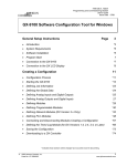
Table of Contents
Chapter
Page
1. Introduction ...................................................................................................................... 3
2. Overview of Operation ..................................................................................................... 7
3. Disk Operations .............................................................................................................. 10
4. Product Handlers Menu ................................................................................................. 12
5. Programming Records ................................................................................................... 14
6. Sending (Loading) Records ........................................................................................... 27
7. Receiving (Copying) Records ........................................................................................ 29
8. Passwords ...................................................................................................................... 30
9. Lockcodes ...................................................................................................................... 32
10. Updating Handlers ....................................................................................................... 33
11. Deleting Handlers ......................................................................................................... 41
12. Programmer Time Out ................................................................................................. 42
13. Help Screens ................................................................................................................ 43
14. Inside the Programmer ................................................................................................. 44
15. Troubleshooting Guide ................................................................................................. 46
D5200 Security Utility Passwords and Lockcodes Record Sheet ................................ 48
D5200 Programmer Memory Worksheet ..................................................................... 49
74-06176-000-B 9/95
D5200 Programmer Operation Manual
Page 1
© 1991-1995 Radionics
A-5200-030-20
020
List of Figures
Figure
Page
1. D5200 Programmer ........................................................................................................... 4
2. D5200 Structural Overview ............................................................................................... 7
3. Programmer Levels ........................................................................................................... 8
4. Handler, Help File, and Record Size ............................................................................... 10
5. Password Display ............................................................................................................ 12
6. Selecting the 7112 Product Handler ............................................................................... 14
7. Records in the 7112 Handler Menu ................................................................................ 14
8. D7112 Product Handler ................................................................................................... 15
9. Modules in the 7112 NEWRECORD Menu ..................................................................... 17
10. Categories in the 7112 PANEL WIDE PARAMETERS Module .................................... 17
11. Program Items in the 7112 PHONE CATEGORY Menu ............................................... 18
12. Indexed Program Items ................................................................................................. 20
13. Saving a Record ............................................................................................................ 20
14. Replacing a Record ....................................................................................................... 22
15. Receiving (Copying) a Record ...................................................................................... 23
16. Receiving (Copying) – Specifying Disks ....................................................................... 23
17. Deleting a Record ......................................................................................................... 24
18. Making a Program Item Invisible ................................................................................... 25
19. Locking a Record .......................................................................................................... 26
20. Connecting the D5200 to a Panel with a 4-Pin Programmer Connector ....................... 28
21. Connecting the D5200 to a Panel with a Phone Jack Programmer Connector ............ 28
22. Update Methods ............................................................................................................ 33
23. Update Times (Minutes:Seconds) ................................................................................. 33
24. Disk to Disk Handler Copy ............................................................................................ 34
25. Connecting to the Radionics Update System ................................................................ 35
26. "RECEIVING Programmer" Update Progress ............................................................... 36
27. RS-232 Update Configuration ....................................................................................... 37
28. "SENDING Programmer" Update Progress .................................................................. 38
29. TELCO Update Configuration ....................................................................................... 39
30. Inside the Programmer .................................................................................................. 44
74-06176-000-B 9/95
D5200 Programmer Operation Manual
Page 2
© 1991-1995 Radionics
A-5200-030-20
030
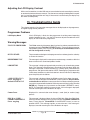
1. Introduction
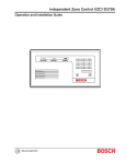
The D5200 Programmer is a state of the art rugged, compact tool for programming the
advanced line of Radionics security products. The D5200 features include a four-line LCD
display, compact keyboard, and expandable memory.
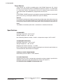
Features
•
LCD Display
The four-line LCD display is used to provide product handler programming information,
help screens for prompts and program items, and status information.
•
Keyboard
The programmer keyboard features standard letter layout, function keys for sending
(loading) and receiving (copying) records, and "navigation" keys to assist the user in
moving through product handler levels. A Help key provides immediate access to
programming assistance.
•
Removable Data Storage
A connector for a state of the art removable RAM card (32 kbytes to 1 Mbyte) is provided
in the D5200. RAM cards with different programmed records can easily be interchanged.
See Removable RAM Card in the Specifications section for available sizes. The D5200
Programmer is shipped with an internal 128 kbyte RAM disk for product handler and
record storage.
•
Customize Product Handlers
Product handler records can be customized using the VisMode feature. Designate as
invisible selected program items, categories – even entire modules.
•
Password Protection
Protect your data by limiting access to programmer functions. Eight passwords with
specific function access authority can be programmed.
•
Easy to Update
Conveniently update your programmer - add new handlers and help files – over the
phone lines. Transfer handlers and records between D5200 programmers quickly and
easily via the built-in RS-232 serial interface.
•
Help Screens
Built-in help messages provide guidance for D5200 operation and product handler
programming.
•
Power Saving Timeout
Automatic timeout feature safely powers down the D5200 after a programmed amount
of time.
74-06176-000-B 9/95
D5200 Programmer Operation Manual
Page 3
© 1991-1995 Radionics
A-5200-030-40
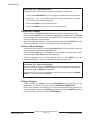
040
AC ADAPTER
PORT
CONTROL/
COMMUNICATOR
PORT
EXTERNAL
POWER
+
AUXILIARY
PORT
COMMUNICATOR
RS-232
PORT
AUXILIARY
TELCO
PORT
5200
to
5200
-
TO / FROM
PHONE
D5200
RS-232>A
or
RS-232>B
POSITIVE TIP POLARITY
A>RS-232
or
B>RS-232
RECEIVING
PROGRAMMER
TELCO>A
or
TELCO>B
RADX UPDATE
SENDING
PROGRAMMER
A>TELCO
or
B>TELCO
LCD DISPLAY
--D5200-PROGRAMMER-----Radionics-Inc------Rev--[##.##]---Password:-❏---------
FUNCTION KEYS
➞ ➞
KEYBOARD
NAVIGATIONAL
KEYS
ENTER
GROUP
!
1
@
2
#
3
$
4
%
5
:
6
&
7
*
8
(
9
)
0
Q
W
E
R
T
Y
U
I
O
P
A
CAP
LOCK
=
+
ON
HELP
CANCEL
EXIT
GROUP
RECV
(COPY)
SEND
(LOAD)
CLEAR
➞
S
Z
D
X
SHIFT
F
C
G
V
H
B
J
N
➞
M
ENTER
L
K
<
,
SPACE
BACK
SPACE
>
.
SHIFT
?
/
_
-
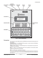
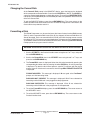
Figure 1: D5200 PROGRAMMER
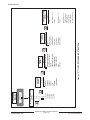
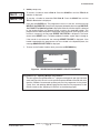
Connectors
Four connectors are provided to interface the D5200 to control/communicators (panels) and
other devices.
COMMUNICATOR: The COMMUNICATOR connector is used to interface the D5200 to
programmable devices such as panels.
TELCO: Product handlers in the D5200 Programmer can be updated via the phone lines
using the TELCO connector.
RS-232: Handlers in the D5200 Programmer can be updated at 19.2k baud by another
D5200 using the RS-232 serial connector.
AUX: An auxiliary port is provided for future use.
A metal strip is provided on the back of the D5200 to hang the programmer on the enclosure
of a panel. A camera strap can be attached to the D5200 using the two holes located below
the metal strip.
74-06176-000-B 9/95
D5200 Programmer Operation Manual
Page 4
© 1991-1995 Radionics
A-5200-030-40
050
Power Sources
Three sources are available to provide power to the D5200 Programmer: AC, internal
batteries, and a panel power source. The D5200 can operate on any one – or a combination
of – these three sources. The programmer also has an automatic time-out feature which
safely powers down the D5200 after a programmed amount of time.
AC
An EXTERNAL POWER connector is provided for connecting the D5200 to a standard AC
power source using an AC adapter (Radio Shack part# 273-1652A).
Batteries
Four alkaline C cell batteries inside the programmer provides power when other sources are
not available. Tests conducted by Radionics have indicated that the programmer can operate
on high-quality alkaline batteries (with no other power source) for 8 hours of continuous use.
Panel
The D5200 can also obtain power from a connection to a control/communicator.
Specifications
PROGRAMMER
Operating Temperature: 32°F to 122°F
Storage Temperature: -20°F to 150°F
Non-condensing Relative Humidity: 5 to 85% at temperature range of -20°F to 150°F
PROGRAMMER KEYBOARD
Operating Temperature: -40°F to 149°F
Storage Temperature: -40°F to 149°F
Maximum Key Presses (each key): 1.5 million
NOTE: Exposure to heat and direct sunlight exceeding the manufacturer's specifications can
cause discoloration, delamination of the keypad.
EXTERNAL POWER TRANSFORMER
Radio Shack part# 273-1652A: 12VDC, 500 mA
FCC QUALIFICATIONS
Complies with FCC Parts 15 and 68 when connected to a phone network in parallel with a
telephone or other device with ringing detection circuitry (see Figure 27).
FCC REGISTRATION NUMBER: AJ9USA-65062-AL-E
74-06176-000-B 9/95
D5200 Programmer Operation Manual
Page 5
© 1991-1995 Radionics
A-5200-030-60
060
Removable RAM Card
Call Radionics Customer Service
For Removable RAM Card Information
Refer to Technogram 73-07504-000
1-800-538-5807
74-06176-000-B 9/95
D5200 Programmer Operation Manual
Page 6
© 1991-1995 Radionics
A-5200-030-60
070
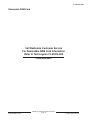
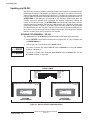
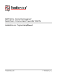
2. Overview of Operation
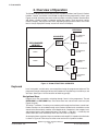
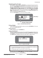
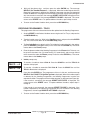
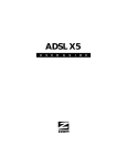
The D5200 is designed to store records for several product handlers (see Figure 2). Product
handlers, records, and utilities in the D5200 are organized into programming "levels" (see
Figures 3 and 8). At the top level are the titles of product and utility handlers stored on Disk
A/B. When a product handler is selected, record titles appear. Each record can contain
module, category, and program item levels, depending on the product handler. The current
level is always displayed in the top "status line" of the LCD display.
RECORDS
HANDLERS
PROGRAMMER
MEMORY
Prog
Prog
Prog
Prog
Prog
Prog
Prog
Prog
Prog
Item
Item
Item
Item
Item
Item
Item
Item
Item
1 Yes
2 No
3 2
4 Yes
5 No
6 2
7 Yes
8 No
8 2
7112
HANDLER
DISK A
DISK B
Prog
Prog
Prog
Prog
Prog
Prog
Prog
Prog
Prog
7112 COMMERCIAL
SUPERVISED
Item
Item
Item
Item
Item
Item
Item
Item
Item
1 Yes
2 No
3 2
4 Yes
5 No
6 2
7 Yes
8 No
8 2
7112 RESIDENTIAL
Prog
Prog
Prog
Prog
Prog
Prog
Prog
Prog
Prog
Item
Item
Item
Item
Item
Item
Item
Item
Item
1 Yes
2 No
3 2
4 Yes
5 No
6 2
7 Yes
8 No
8 2
7112 RESIDENTIAL
WITH FIRE
Prog
Prog
Prog
Prog
Prog
Prog
Prog
Prog
Prog
Item
Item
Item
Item
Item
Item
Item
Item
Item
1 Yes
2 No
3 2
4 Yes
5 No
6 2
7 Yes
8 No
8 2
8112 COMMERCIAL
SUPERVISED
Prog
Prog
Prog
Prog
Prog
Prog
Prog
Prog
Prog
8112
HANDLER
Prog
Prog
Prog
Prog
Prog
Prog
Prog
Prog
Prog
Item
Item
Item
Item
Item
Item
Item
Item
Item
Item
Item
Item
Item
Item
Item
Item
Item
Item
1 Yes
2 No
3 2
4 Yes
5 No
6 2
7 Yes
8 No
8 2
1 Yes
2 No
3 2
4 Yes
5 No
6 2
7 Yes
8 No
8 2
8112 RESIDENTIAL
8112 RESIDENTIAL
WITH FIRE
Figure 2: D5200 STRUCTURAL OVERVIEW
Keyboard
Level "navigation" and data entry are accomplished using the programmer keyboard. The
programmer contains three types of keys on its keyboard: navigation keys, function keys, and
data keys. (See Figure 1 for the locations of these key groups).
Navigational Keys
Program items are accessed by navigating through "levels" of the programmer. The red
ENTER GROUP and EXIT GROUP keys are used to enter into and exit from each level (see
Figures 3 and 8).
The red up ↑ and down ↓ arrow keys are used to scroll through the list of items at each level.
Product handlers can be scrolled through at the Product Handler level, record titles can be
viewed at the Record level, modules at the Module level, Categories at the category level,
and program items at the Program Item level. The red left ← and right → arrow keys are
used to move the cursor horizontally within one line of the LCD display.
An example of how navigational keys are used to move through D7112 product handler levels
is shown in Figure 8. These keys have the same function for all product handlers.
74-06176-000-B 9/95
D5200 Programmer Operation Manual
Page 7
© 1991-1995 Radionics
A-5200-030-80
080
ENTER
GROUP
PRODUCT
HANDLERS
2071 12
ENTER
GROUP
ENTER
GROUP
Program Items
2071 Handler Records
NEWRECORD 17
DELETE 24
Same for all handlers.
COPY 23
VISMODE25
LOCKRECORD 26
14
Modules
17
4112
4112 Handler Records
6112
6112 Handler Records
Modules
636
636 Handler Records
Program Items
7112
7112 Handler Records
Modules
8112
8112 Handler Records
Modules
EXIT
GROUP
ENTER
GROUP
UTILITIES
DISKSTAT
10
EXIT
GROUP
Program Items
Program Items
Categories
Program Items
Program Items
EXIT
GROUP
EXIT
GROUP
ENTER
GROUP
SEND 27
(LOAD)
Current Disk 10
SizeKilobytes10
FreeKilobytes 10
Passwords30
SECURITY
18
U1Password
User#:
U#Password
U#PasswordEnable
U#Delete Record
U#Delete Handler
U#Edit Lockcodes
U#Edit Paswords
U#Edit Vis/Invis
U#Update Handler
U#Replace Record
U#Format Disk
U#Lock Record
Lockcodes 32
RECV 29
(COPY)
Primary Lock
Lock#:
Lockcode#:
Format Disk11
Disk: B
Time Out:42
UPDATE 33
HandName:
Include Help:
Phone: 39
Mode: A -> B 34
B -> A34
A->TELCO 39
TELCO->A 35
B->TELCO 39
TELCO->B 35
A->RS232 37
RS232->A 38
B->RS232 37
RS232->B 38
DELETE 41
HandName: 41
HelpName: 41
5200 OFF 9
EXIT
GROUP
EXIT
GROUP
NOTE: Small numbers (e.g. 35) indicate the page on which discussion of the item begins.
Figure 3: PROGRAMMER LEVELS
74-06176-000-B 9/95
D5200 Programmer Operation Manual
Page 8
© 1991-1995 Radionics
A-5200-030-80
090
Function Keys
Six function keys simplify the use of the programmer.
ON: The red ON key switches the programmer on. This key does not power down the
programmer. The D5200 is switched off by selecting 5200 OFF in the PRODUCT HANDLERS
menu, or it powers down automatically after the programmed Time Out time has elapsed.
HELP: The red HELP key switches the programmer into help mode. (See the Help Mode
chapter for more information.)
CANCEL: The red CANCEL key erases unENTERed program item data and replaces it with
the previously entered data.
CLEAR: The red CLEAR key erases unENTERed or ENTERED program item data, and
replaces it with blank spaces.
RECV (COPY) : The red RECV (COPY) key initiates a transfer of data from a product into the
D5200 Programmer.
SEND (LOAD): The red SEND (LOAD) key initiates a transfer of data from the D5200 Programmer
to another product.
Data Keys
The white keys on the keyboard are used for data entry.
Helpful Tones
The D5200 Programmer emits four distinct sounds, which notify the user of key presses, data
acceptance/rejection, and system errors.
CLICK
A short, sharp click occurs every time a key is pressed. The programmer does not click when
the ON, CAP LOCK, and SHIFT keys are pressed.
PIP
A short, single frequency tone indicates that the key pressed or data entered was accepted.
TWEEDLE
A quick series of pips indicates that the key pressed or data entered was invalid or
inappropriate.
BUZZ
A sour, flat tone indicates a system error, except when entering a product. Panel not
connected to D5200, low battery condition, programmed Time Out elapsed, changing panel
series type, deleting handlers and records are examples.
74-06176-000-B 9/95
D5200 Programmer Operation Manual
Page 9
© 1991-1995 Radionics
A-5200-030-100
3. Disk Operations
The D5200 contains memory which holds programmer data. This memory includes internal
battery-backed RAM chips which are permanently attached to the D5200 circuit board, and
removable RAM cards.
•
•
The internal battery-backed RAM is referred to as disk A.
The removable RAM card is referred to as disk B.
Even though data may be stored on several RAM cards, the RAM card which is currently
plugged into the programmer is always considered disk B.
Disk Status
The size of a disk and the amount of memory currently available on a disk can be viewed using
the DISKSTAT feature. To view this information, scroll to DISKSTAT from the Product
Handlers menu using the red ↓ or ↑ keys, and press the red ENTER GROUP key.
Current Disk: Disk A is the internal battery-backed RAM. Disk B is the removable RAM
card. The programmer can display data from only one disk at a time (the disk indicated
by Current Disk). See Changing the Current Disk to set up the programmer to display
data from a different disk.
SizeKilobytes: Each disk can hold a certain amount of data, expressed in units of bytes,
kilobytes (K), or Megabytes (Mb). 1024 bytes = 1 K, 1024K = 1 Mb. The total amount of
memory of the Current Disk (A or B) is displayed in SizeKilobytes.
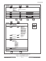
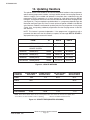
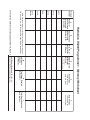
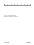
FreeKilobytes: Handlers, records, and help files take up a certain amount of memory
on a disk (see Figure 4). The FreeKilobytes field displays the amount of memory on
the Current Disk (A or B) that is currently available for storing additional handlers, help
files, and records. Figure 4 contains the following information:
Handler Size: The amount of memory consumed by the actual handler.
Help File Size: The amount of memory consumed by the handler help file.
Record Size: The amount of memory consumed by each record.
Space O/S Allots: The amount of memory that is reserved for use (by the Operating
System) when the first record for the handler is saved.
Number of Records: The number of records that can be saved in the memory
reserved by the Space O/S Allots. When the number of records saved exceeds this
amount (i.e. five D4112 records), another block of memory (Space O/S Allots) is
reserved.
If your disk (A or B) is 512K or above, use the 512K and Above Columns in Memory Worksheet.
If your disk is below 512K, use Standard Columns.
PRODUCT
HELP FILE 512K
HANDLER 512K
RECORD
&
&
SIZE
SIZE
SIZE
ABOVE
ABOVE
SPACE O/S
ALLOTS
512K
&
ABOVE
NUMBER OF 512K
&
RECORDS ABOVE
D2071
5K
6K
2K
2K
35 bytes
2K
4K
29
58
D4112
9K
10K
5K
6K
173 bytes
2K
4K
5
11
D6112
11K
12K
7K
8K
179 bytes
2K
4K
5
11
D636
5K
6K
1K
2K
220 bytes
2K
4K
4
9
D7112
22K
22K
26K
612 bytes
2K
4K
1
3
D8112 SERIES
25K
26K
2689 bytes
17K
18K
6
6
Figure 4: HANDLER, HELP FILE, AND RECORD SIZE
74-06176-000-B 9/95
D5200 Programmer Operation Manual
Page 10
© 1991-1995 Radionics
A-5200-030-100
Changing the Current Disk
At the Current Disk prompt in the DISKSTAT display, press the letter on the keyboard
which corresponds to the desired disk. Press the white ENTER key. (NOTE: The SPACE bar
cannot be used to toggle between available disk drives.) The message LOGGED ON DISK!
is displayed, and the SizeKilobytes and FreeKilobytes fields are updated to reflect the status
of the new Current Disk.
To exit the DISKSTAT display, press the red EXIT GROUP key. The cursor returns to the
Product Handlers level of the Current Disk. NOTE: When the Programmer is switched on, the
Current Disk always defaults to disk A.
Formatting a Disk
The D5200 Programmer can be used to format the internal battery-backed RAM memory
(Disk A) and the removable RAM cards (Disk B). As shipped, the internal RAM Disk A is
already formatted. Each new removable disk (Disk B) used with the programmer must be
formatted. NOTE: This feature is password dependent . If the programmer is logged onto with
a password that does not have the authority to format disks, the message ACCESS DENIED
is displayed when trying to access this feature.
WARNING: All information stored on the disk will be lost when the disk is formatted!
1. Scroll to SECURITY in the Product Handlers menu using the red ↓ or ↑ keys, and press
the red ENTER GROUP key.
2. Scroll to the FormatDisk item in the SECURITY menu using the red ↓ or ↑ keys, and
press the red ENTER GROUP key.
3. The FormatDisk menu is displayed. Select the disk to be formatted by pressing the
corresponding disk letter and then pressing the white ENTER key. A warning message
is displayed. To abort the disk format process, type N. To continue with the format
process, press Y. If the format is successful, the message RAM FORMAT COMPLETED
is displayed.
FORMAT ABORTED: This message is displayed if N was typed at the Continue?
prompt, or if disk formatting failed.
RAM CARD NOT PRESENT: This message is displayed if Disk B was selected for
formatting and the RAM card is not plugged into the programmer.
RAM DISK PROTECTED: This message is displayed if Disk B was selected for
formatting and the RAM card in the programmer is write-protected.
4. To exit the FormatDisk display, press the red EXIT GROUP key. The cursor returns to
the SECURITY menu.
5. To exit the SECURITY menu, press the red EXIT GROUP key. The cursor returns to the
Product Handlers level.
74-06176-000-B 9/95
D5200 Programmer Operation Manual
Page 11
© 1991-1995 Radionics
A-5200-030-120
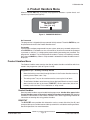
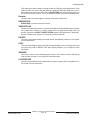
4. Product Handlers Menu
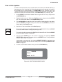
When the D5200 ON button is pressed, the programmer executes a system check, and
requests a password (see Figure 5).
D5200 PROGRAMMER
Radionics Inc.
Rev [# # . # #]
Password:
Figure 5: PASSWORD DISPLAY
No Passwords
The programmer is shipped with no passwords initially entered. The white ENTER key can
be pressed to advance to the Product Handlers level.
Passwords
If passwords have been programmed into your system, enter your password and press the
white ENTER key. (Passwords are not case-sensitive.) As each character of the password
is pressed, an asterisk (✳) is displayed to prevent others from seeing your password. The
programmer "tweedles" if an invalid password is entered. To clear an erroneous password,
press the red CANCEL key. When a valid password is entered the Product Handlers menu is
displayed.
Product Handlers Menu
The Product Handlers menu contains the titles of product handlers and utilities which are
stored in the programmer (refer to Figures 4 and 8).
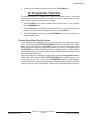
Programmer Tips – Scrolling and Wrap Around
•
Move the flashing cursor block through the items in the Product Handlers menu by
pressing the red down arrow ↓ key.
•
The red up arrow ↑ key can be used to move the cursor up the list of items.
•
Three Product Handlers menu items are always displayed. When the cursor is moved
down from the last item in the menu (5200 OFF), the first menu item (title of first
handler) scrolls into view. This is referred to as "wrap around".
Product Handlers
Several product handlers are pre-loaded into the programmer. Handler titles appear in the
Product Handlers menu in the order in which the handlers were loaded. See Updating
Handlers to add handlers to the Product Handlers menu. See Programming Records for
information on entering data using product handlers.
DISKSTAT
The DISKSTAT menu provides disk information such as current disk drive (A or B), total
amount of disk space, and the amount of disk space which is available for entering new data.
See Disk Operations for more information.
74-06176-000-B 9/95
D5200 Programmer Operation Manual
Page 12
© 1991-1995 Radionics
A-5200-030-120
SECURITY
The SECURITY menu includes items for programming passwords and panel lockcodes,
formatting disks, and programming the D5200 automatic power-down time. See the Passwords
and Lockcodes sections for more information.
UPDATE
This menu is provided for updating (copying) product handlers between disks on the same
programmer, or between the disks of two different programmers via the phone lines or RS232 interface. See Updating Handlers for more information.
DELETE
This menu item allows product handlers and help files to be deleted from D5200 memory. See
Deleting Handlers for more information.
5200 OFF
This menu item is used to power down the programmer. To turn off the D5200, move the
cursor to 5200 OFF and press the red ENTER GROUP key.
NOTE: The D5200 powers down automatically if no keys have been pressed for the amount
of time programmed in the programmer SECURITY menu Time Out parameter. See
Programmer TimeOut for more information.
Selecting a Product Handlers Menu Item
Use the red ↑ and ↓ arrow keys to move the cursor through the list of items in the Product
Handlers menu. When the cursor flashes on the desired item, press the red ENTER GROUP
key. The next chapters of this manual describe how to "navigate" within each item in the
Product Handlers menu.
Exiting the Product Handlers Menu
The cursor can be returned to the password display from the Product Handlers level by
pressing the red EXIT GROUP key. This returns the display to the Password entry prompt.
The programmer can be powered down by returning to the Product Handlers level and
selecting the 5200 OFF prompt.
74-06176-000-B 9/95
D5200 Programmer Operation Manual
Page 13
© 1991-1995 Radionics
A-5200-030-140
5. Programming Records
The example in this chapter shows how to program a record for a D7112 Control/
Communicator. The same principles apply to the programming of other product handlers.
Refer to Figure 8, which is a "map" of the D7112 Product Handler.
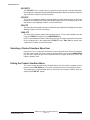
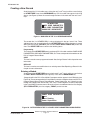
Selecting a Handler
Starting from the Product Handlers level, scroll through the list of product handlers and
utilities (using the red ↓ and ↑ keys) until the cursor flashes on the 7112 product handler title
(see Figure 6). Press the red ENTER GROUP key.
PRODUCT HANDLERS
636
7112
6112
Figure 6: SELECTING THE 7112 PRODUCT HANDLER
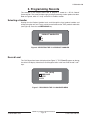
Record Level
The 7112 Record level menu is displayed (see Figure 7). 7112 [rev#] appears on the top
line of the LCD display. Move the cursor through the items in the menu with the red ↓ and ↑
keys.
7112 [##.##]
NEWRECORD
DELETE
COPY
Figure 7: RECORDS IN THE 7112 HANDLER MENU
74-06176-000-B 9/95
D5200 Programmer Operation Manual
Page 14
© 1991-1995 Radionics
74-06176-000-B 9/95
↓
5200 OFF
DELETE
UPDATE
SECURITY
DISKSTAT
8112
7112
636
6112
4112
2071
ENTER
GROUP
PRODUCT HANDLER
LEVEL
D5200 PROGRAMMER
Radionics Inc.
Rev [# # . # #]
Password:
PASSWORD
DISPLAY
Phone
D5200 Programmer Operation Manual
Page 15
RF Parameters
Bell Parameters
SAVE
REPLACE
Figure 8: D7112 PRODUCT HANDLER STRUCTURE
Phone 3
Miscellaneous
POINT ASSIGNMENTS
LOCKRECORD
No
Yes
Yes
Two Phone Lines No
Alarm on Fail No
Phone Supv Time
DTMF Dialing No
Point/User Flag No
Modem Format
Modem Format
Test Reports
Phone 2
Modem Format
Phone 1
PROGRAM ITEM
LEVEL
COMMAND CENTER
ENTER
GROUP
VISMODE
RAM Parameters
Power Supervision
RELAYS
DELETE
CMD CENTER FUNCTIONS
Phone Routing
PASSCODE WORKSHEET
RECORD3
COPY
Phone
AREA WIDE PARAMETERS
RECORD2
ENTER
GROUP
PANEL WIDE PARAMETER
NEWRECORD
CATEGORY
LEVEL
PANEL WIDE PARAMETER
ENTER
GROUP
MODULE
LEVEL
RECORD1
NEWRECORD
7112 [##.##]
RECORD
LEVEL
A-5200-030-140
© 1991-1995 Radionics
A-5200-030-160
The handler title is always shown in the top line of the LCD display at the Record level. Three
additional items are always displayed below the product handler title. When the cursor is
moved down from the last item in the menu (LOCKRECORD), the first menu item (title of first
D7112 record) scrolls into view. The 7112 Record level menu contains the following items:
Records
The titles of D7112 records appear at the top of the Record level menu.
NEWRECORD
NEWRECORD is used to create new records.
TIMEOUTSAVE
This title is included in the list only if a record was still open when the D5200 Programmer went
into a power-down timeout. If a timeout record exists, the programmer beeps when the
handler is entered, and SAVE TIMEOUT RECORD appears among the items in the display.
See the TimeOut Save section in this chapter for more information.
DELETE
This utility is provided for deleting unwanted records. See Deleting a Record in this chapter
for more information.
COPY
This utility is provided for copying the programmed parameters from an existing record and
saving the data under a different name. See Copying Records in this chapter for more
information.
VISMODE
This utility is used to make selected program items in this handler invisible. See Making
Program Items Invisible in this chapter for more information.
LOCKRECORD
This utility is provided to prevent modifications to specific records. See Locking Records in
this chapter for more information.
74-06176-000-B 9/95
D5200 Programmer Operation Manual
Page 16
© 1991-1995 Radionics
A-5200-030-160
Creating a New Record
Scroll through the 7112 handler menu (using the red ↓ and ↑ keys) until the cursor flashes
on NEWRECORD. Press the red ENTER GROUP key. D7112 module titles appear in the LCD
display (see Figure 9). Move the cursor through the items in the menu with the red ↓ and ↑
keys.
NEWRECORD
PANEL WIDE PARAMETER
AREA WIDE PARAMETERS
PASSCODE WORKSHEET
Figure 9: MODULES IN THE 7112 NEWRECORD MENU
The record title (i.e. NEWRECORD) is always displayed in the top "status" line. Three
additional items are always displayed in the NEWRECORD menu. When the cursor is moved
down from the last item (REPLACE), the first item (PANEL WIDE PARAMETER) scrolls into
view. The NEWRECORD menu contains the following items:
Programming
The majority of the NEWRECORD menu is made up of D7112 handler modules: PANEL WIDE
PARAMETERS, AREA WIDE PARAMETERS, etc. These correspond to the modules on the
D7112 Program Record Sheet.
SAVE
This item is used to save a programmed record. See Saving a Record in this chapter for more
information.
REPLACE
This item is used to save modifications to an existing record. See Replacing a Record in this
chapter for more information.
Entering a Module
Scroll through the NEWRECORD menu (using the red ↓ and ↑ keys) until the cursor flashes
on PANEL WIDE PARAMETER (see Figure 9). Press the red ENTER GROUP key.
Categories within the D7112 Panel Wide Parameters section appear in the LCD display (see
Figure 10). These correspond to the Panel Wide Parameters categories shown on the D7112
Program Record Sheet (Phone, Phone Routing, Power Supervision, etc.). Move the cursor
through the category titles with the red ↓ and ↑ keys. Three categories are always displayed
in the Panel Wide Parameters menu. When the cursor is moved down from the last category
(BELL PARAMETERS), the first category (PHONE) scrolls into view.
PANEL WIDE PARAMETER
Phone
Phone Routing
Power Supervision
Figure 10: CATEGORIES IN THE 7112 PANEL WIDE PARAMETERS MODULE MENU
74-06176-000-B 9/95
D5200 Programmer Operation Manual
Page 17
© 1991-1995 Radionics
A-5200-030-180
Entering a Category
Scroll through the Panel Wide Parameter categories (using the red ↓ and ↑ keys) until the
cursor flashes on Phone (see Figure 10). Press the red ENTER GROUP key.
Program items in the Phone category appear in the LCD display (see Figure 11). These
correspond to the program items in the Phone category shown on the D7112 Program Record
Sheet (Phone 1, Modem Format, Phone 2, etc.). Move the cursor through the program items
with the red ↓ and ↑ arrow keys. When the cursor is moved down from the last item (Two
Phone Lines), the first item (Phone 1) scrolls into view. Some program items have twoline prompts. These prompts are provided for long strings of data (i.e. the Phone 1 program
item) and for program item title clarity (i.e. the A1 Aux Relay Uses Bell Time prompt in
the Area Parameters category of the AREA WIDE PARAMETERS module).
Phone 1
Phone
14155551212
Modem Format Yes
Figure 11: PROGRAM ITEMS IN THE 7112 PHONE CATEGORY MENU
Entering Data
Four types of data can be entered for program items:
Yes/No
Yes or No is selected by typing Y or N, or pressing the SPACE bar (which toggles the entry
between Y and N).
Data
Data is entered using the D5200 Programmer keyboard.
Choice Lists
An entry is selected using the SPACE bar, which scrolls among the available choices.
Indexed Group
The first item in an indexed group modifies the titles of the rest of the items in the group.
Data Entry Example
1. Move the cursor to the Phone 1 item. The cursor flashes in the blank space to the right
of the Phone 1 label.
2. Enter a phone number by pressing number keys on the programmer keyboard:
(Example: 14155551212 in Figure 10).
3. When the number has been entered, press the white ENTER key on the programmer
keyboard.
Programmer Tips – Sounds
74-06176-000-B 9/95
•
Each time a valid data entry is made, the programmer makes a "pip" sound.
•
When an inappropriate entry is made, such as a the letter "Q" in the Phone 1 program
item, the programmer makes a "tweedle" sound.
D5200 Programmer Operation Manual
Page 18
© 1991-1995 Radionics
A-5200-030-180
Programmer Tips – Making Corrections
The following keys can be used to change data entered for a program item:
•
Use the white BACKSPACE key on the programmer keyboard to erase characters.
•
Use the red ← and → arrow keys to move the cursor to any character in the entry.
(The arrow keys do not erase characters.)
•
Use the red CLEAR key to erase the entire entry.
•
Use the red CANCEL key to return the entry to its default entry.
Yes/No Entry Example
Move the cursor to Modem Format. The cursor flashes on the default entry Yes.
Press the white SPACE bar on the keyboard to toggle the entry to Yes. Pressing the SPACE
bar again toggles the entry back to No. Yes and No entries can also be achieved by pressing
the Y key or the N key on the keyboard.
When the appropriate Yes/No entry has been selected, press the white ENTER key on the
programmer keyboard. The cursor moves down to the next program item.
Choice List Entry Example
Using the red ↓ key, move the cursor to Phone Supv Time. The cursor flashes in the blank
space to the right of the Phone Supv Time label.
Press the white SPACE bar on the keyboard to scroll through the programming choices
available: 2Min, 4Min, 8Min, blank (No Supervision).
When the appropriate entry has been selected, press the white ENTER key on the
programmer keyboard. The cursor moves down to the next program item.
Programmer Tip – Choice List Data Entry
Only the entries displayed using the SPACE bar will be accepted by the programmer for
choice list entries. If numbers or letters are typed in using the keyboard, the programmer
will "tweedle" when the ENTER key is pressed.
To view valid choices, move the cursor back to the first character, using the red CANCEL,
CLEAR, or ← key, and press the SPACE bar.
Exiting a Category
To exit a category (i.e. Phone), press the red EXIT GROUP key. The cursor returns to the
module level, and flashes on the next module title AREA WIDE PARAMETERS.
NOTE: The programmer will "tweedle" if the cursor is flashing on program item data that has
not been entered. Press the white ENTER key to enter data or the red CANCEL key to return
the previous entry, and then press the red EXIT GROUP key.
74-06176-000-B 9/95
D5200 Programmer Operation Manual
Page 19
© 1991-1995 Radionics
A-5200-030-200
Indexed Group Entry Example
Exit the Phone category using the red EXIT GROUP key as described in the previous section.
Move the cursor to the Phone Routing category in the Panel Wide Parameters module, and
press the red ENTER GROUP key. The cursor flashes on the default entry of 1 to the right of
the Phone program item. Note that the program items below Phone also have the number
1 Fire Alarm/Res, Ph1
1 Fire Tbl/Res, etc.). Press the 2 key and the white ENTER
1 (Ph1
2 Fire Alarm/Res,
key. The titles of the next program items change to reflect this entry (Ph2
2 Fire Trouble/Res, etc.). The program items within the Phone Routing group are
Ph2
indexed to the entry of the Phone program item.
Press the red EXIT GROUP key to exit the Phone Routing category.
Phone Routing
Phone 2
Ph2 Fire Alarm/Res P
Ph2 Fire Tbl/Res P
This entry ...
... changes these prompts
Figure 12: INDEXED PROGRAM ITEMS
Exiting a Module
To exit a module such as Panel Wide Parameters, press the red EXIT GROUP key. The cursor
returns to the NEWRECORD menu.
Exiting a Record
To exit a record, press the red EXIT GROUP key.
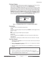
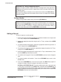
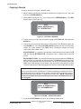
Saving a New Record
If changes have been made to any program items, the SAVE display appears (see Figure 13).
To save a new record, type a name (up to 12 characters) in the NAME field, and press the
white ENTER key. A message indicates that the record has been saved. The cursor remains
in the SAVE display, allowing the record to be saved under an additional name.
SAVE
NAME: RESIDENTIAL4
Figure 13: SAVING A RECORD
Programmer Tip – Record Names
•
It is recommended that programmer prompts such as NEWRECORD, LOCKRECORD,
VISMODE, COPY, DELETE, not be used as record names.
•
The programmer does not accept a blank (all spaces) record name.
The cursor returns to the NEWRECORD menu, and flashes on REPLACE. To return to the
D7112 record level, press the red EXIT GROUP key.
74-06176-000-B 9/95
D5200 Programmer Operation Manual
Page 20
© 1991-1995 Radionics
A-5200-030-200
Programmer Tip – Saving and Replacing Records
Whenever changes have been made to record data, the programmer always goes to the
SAVE display to provide the user with an opportunity to save the changes under the same
(or different) name.
When the SAVE display is exited, the cursor automatically flashes on the REPLACE item
in the menu, to provide the user with another chance to save any changes that have been
made to the record.
Exiting a Handler
To return to the Product Handlers level, press the red EXIT GROUP key.
Programmer Tip – Creating New Records from a Template
A programmed record ("template") can be used to create new records. (It is not necessary
to always start with NEWRECORD.) A "template" is especially useful when only a few items
need to be changed to "customize" an existing record. See the next section Editing a
Record for more information. NOTE: NEWRECORD can be unlocked.
Editing a Record
To make changes to an existing record:
1. Scroll to the appropriate product handler from the Product Handlers menu using the red
↓ or ↑ keys, and press the red ENTER GROUP key.
2. Scroll to the appropriate record title using the red ↓ or ↑ keys, and press the red ENTER
GROUP key.
3. For product handlers with modules: Scroll to the appropriate module using the red ↓ or
↑ keys, and press the red ENTER GROUP key.
4. For modules with categories: Scroll to the appropriate category using the red ↓ or ↑ keys,
and press the red ENTER GROUP key.
5. Scroll to the appropriate program item using the red ↓ or ↑ keys, and edit the entry. Press
the white ENTER key to enter the new data.
6. For modules with categories: Press the red EXIT GROUP key to return to the Categories
level.
7. For product handlers with modules: Press the red EXIT GROUP key to return to the
Modules level.
8. Press the red EXIT GROUP key to exit from the record. The SAVE display appears if
changes have been made to any program item entries in the record.
SAVING as a DIFFERENT Record: To save the edited record under a new name, type
a name (up to 12 characters) in the NAME field, and press the white ENTER key. A
message indicates that the record has been saved. The cursor remains in the SAVE
display, allowing the record to be saved (duplicated) under another name. Press the red
EXIT GROUP key to return to the Record level.
74-06176-000-B 9/95
D5200 Programmer Operation Manual
Page 21
© 1991-1995 Radionics
A-5200-030-220
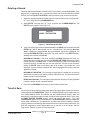
REPLACING the Record: To save the edited record under the original name (replace
the old record), press the red EXIT GROUP key when the SAVE display appears. The cursor
flashes on REPLACE. Press the red ENTER GROUP key. The name of the record
automatically appears in the REPLACE display (see Figure 14). To replace the record,
press the white ENTER key. The message RECORD REPLACED is displayed. Press the
red EXIT GROUP key to return to the Record Level.
NOTE: This feature is password dependent . If the programmer is logged onto with a
password that does not have the authority to replace records, the message ACCESS
DENIED is displayed when trying to access this feature.
DISCARDING CHANGES to the Record: To discard changes that have been made to
the record, simply press the red EXIT GROUP key when the SAVE display appears, and
proceed to step 9.
RECORD NOT REPLACED: This message is displayed if the name entered (i.e. default
current record title not used) does not match any record titles on the current disk. Check
the title entered in the NAME field – it must exactly match the title of the record stored
on the current disk.
REPLACE
NAME: RESIDENTIAL4
Figure 14: REPLACING A RECORD
READ ONLY RECORD: This message is displayed if the record you are trying to replace
is locked. The edited record can be saved only under a different name.
9. Press the red EXIT GROUP key to return to the Record level.
10. Press the red EXIT GROUP key again to return to the Product Handlers level.
74-06176-000-B 9/95
D5200 Programmer Operation Manual
Page 22
© 1991-1995 Radionics
A-5200-030-220
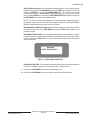
Copying a Record
To copy a record (save it under a different name):
1. Select a product handler from the Product Handlers level using the red ↓ or ↑ keys, and
press the red ENTER GROUP key.
2. Select COPY using the red ↓ or ↑ keys, and press the red ENTER GROUP key. The COPY
display appears (see Figure 15).
COPY
FROM: RESIDENTIAL4
TO: RESIDENTIAL7
Figure 15: COPYING A RECORD
3. Type in the exact name of the record to be copied in the FROM field. Press the white
ENTER key .
4. Type in the name of the new record (up to 12 characters) in the TO field and press the
white ENTER key. The message RECORD COPIED indicates that the record has been
copied. The cursor remains in the COPY display, allowing the record to be saved
(duplicated) under another name.
RECORD EXISTS: If a record has already been saved under the title entered in the TO
field, the message RECORD EXISTS is displayed. Type in a different title for the new
record.
RECORD NOT FOUND: This message is displayed if the name typed in the FROM field
does not match any record titles on the current disk. The FROM title must exactly match
the title of the record stored on the current disk. The title can be verified by exiting the
COPY display and viewing the list of records. If the record title is not displayed, it may be
stored on a different disk. See Changing the Disk section in the Disk Operations chapter.
Programmer Tips – Copying from Disk to Disk
A disk can be specified in the FROM and TO fields by preceding the record titles with the
disk designators A: or B: (see Figure 16). If no disk is specified, the current disk is assumed.
See the Disk Operations section for a definition of "current disk". NOTE: The product
handler associated with the record must be present on the TO disk before the record
can be copied.
COPY
FROM: B:COMMERCIAL3
TO: A:COMMERCIAL1
Figure 16: COPYING – SPECIFYING DISKS
5. Press the red EXIT GROUP key to return to the Product Handler level.
74-06176-000-B 9/95
D5200 Programmer Operation Manual
Page 23
© 1991-1995 Radionics
A-5200-030-240
Deleting a Record
Follow the steps below to delete a record. NOTE: This feature is password dependent. If the
programmer is logged onto with a password that does not have the authority to delete
records, the message ACCESS DENIED is displayed when trying to access this feature.
1. Select the appropriate product handler from the Product Handlers menu using the red ↓
or ↑ keys, and press the red ENTER GROUP key.
2. Select DELETE using the red ↓ or ↑ keys, and press the red ENTER GROUP key. The
DELETE display appears (see Figure 17).
DELETE
NAME: TESTRECORD
Figure 17: DELETING A RECORD
3. Type in the exact name of the record to be deleted in the NAME field, and press the white
ENTER key. (NOTE: Record titles are not case-sensitive.) The message Are You
Sure? is displayed. To proceed with the record deletion, type Y on the keyboard. The
message RECORD DELETED is displayed. The cursor remains in the DELETE display,
allowing other records to be deleted.
RECORD NOT FOUND: If the name entered in the NAME field does not match any
record titles on the current disk, the message RECORD NOT FOUND is displayed. Check
the title entered in the NAME field – it must exactly match the title of the record stored
on the current disk. (Record titles are not case sensitive.) The title can be verified by
exiting the DELETE display and viewing the list of records. If the record title is not
displayed, it may be stored on a different disk. See Changing the Disk section in the Disk
Operations chapter.
RECORD NOT DELETED: This message is displayed if the record you are trying to
delete is the last record in the specific product handler database. The last record of each
product handler cannot be deleted.
READ ONLY RECORD: This message is displayed if the record you are trying to delete
is locked. Locked records cannot be deleted.
4. Press the red EXIT GROUP key to return to the Product Handler level.
TimeOut Save
If a record is still open when the programmer goes into a power-down timeout, the record is
saved under the title TIMEOUTSAVE. (NOTE: If a TIMEOUTSAVE record already exists, the
new TIMEOUTSAVE record will overwrite the old TIMEOUTSAVE record.) When the
programmer is switched on and the handler is entered, the programmer emits a "buzz" tone,
and SAVE TIMEOUT RECORD appears among the items in the display. The name
TIMEOUTSAVE appears in the list of record titles. The TIMEOUTSAVE record can be opened,
saved under a different title, and deleted like any other record. See the Editing a Record,
Copying a Record, and Deleting a Record sections in this chapter for more information. The
time until programmer timeout power-down can be set from 2 to 10 minutes. See the
Programmer TimeOut chapter for more information.
74-06176-000-B 9/95
D5200 Programmer Operation Manual
Page 24
© 1991-1995 Radionics
A-5200-030-240
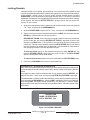
Making Program Items Invisible (VISMODE)
Program items, categories, and modules in each handler can be made invisible using
VISMODE. NOTE: This feature is password dependent. If the programmer is logged onto
with a password that does not have the authority to make program items invisible, the
message ACCESS DENIED is displayed when trying to access this feature. To make a
program item, category, or module invisible:
1. Select a product handler from the Product Handlers menu using the red ↓ or ↑ keys, and
press the red ENTER GROUP key.
2. Select VISMODE using the red ↓ or ↑ keys, and press the red ENTER GROUP key.
3. Enable VISMODE by typing Y at the VisMode prompt, and pressing ENTER.
4. Press the red EXIT GROUP key to return to the Records level.
5. Select a record and press the red ENTER GROUP key. Program items, categories, and
modules cannot be made invisible for locked records such as NEWRECORD.
(NEWRECORD can be unlocked.)
6. For product handlers with modules: The letter V appears to the right of each module title.
To make the entire module invisible, press the letter I and the white ENTER key. To make
an invisible item visible, use the letter V. The I and V entries can be toggled by pressing
the SPACE bar. To leave a module visible and make items within the module invisible,
scroll to the appropriate module using the red ↓ or ↑ keys, and press the red ENTER GROUP
key.
7. For modules with categories: The letter V appears to the right of each category title. To
make the entire category invisible, press the letter I and the white ENTER key. To make
an invisible item visible, use V. I and V can be toggled by pressing the SPACE bar. To
leave a category visible and make program items within the category invisible, scroll to
the category using the red ↓ or ↑ keys, and press the red ENTER GROUP key.
8. At the program item level, the letter V appears to the right of the program item prompt –
where program item data would normally be entered (see Figure 18). To make the item
invisible, press the letter I and the white ENTER key. To make an invisible item visible,
use V. I and V can be toggled by pressing the SPACE bar.
Phone
V
V
Modem Format I
Phone 1
Figure 18: MAKING A PROGRAM ITEM INVISIBLE
9. When the desired program items, categories, and modules have been made invisible,
return to the VISMODE display. (The VISMODE display is reached by using the red EXIT
GROUP key to exit to the Record level, and selecting the VISMODE using the red ENTER
GROUP key.) NOTE: The record is automatically REPLACED with the vismode information
when the record is exited. Set VISMODE to No by pressing N or the SPACE bar, followed
by the white ENTER key. Press the red EXIT GROUP key to return to the Records level.
10. Verify that each program item, category, and module designated invisible does not
appear by reviewing the record.
74-06176-000-B 9/95
D5200 Programmer Operation Manual
Page 25
© 1991-1995 Radionics
A-5200-030-260
Locking Records
Individual records can be locked, preventing data in the record from being edited. Locked
records are copied along with product handlers during programmer-to-programmer and diskto-disk updates, making it easy to transfer custom records. Locked records, including
NEWRECORD, can be unlocked for custom programming. NOTE: This feature is password
dependent. If the programmer is logged onto with a password that does not have the authority
to lock records, the message ACCESS DENIED is displayed when trying to access this
feature. To lock a record:
1. Scroll to the appropriate product handler from the Product Handlers menu using the red
↓ or ↑ keys, and press the red ENTER GROUP key.
2. Scroll to LOCKRECORD using the red ↓ or ↑ keys, and press the red ENTER GROUP key.
3. Type in the exact name of the record to be locked in the NAME field, and press the white
ENTER key. (Record titles are not case-sensitive.)
RECORD NOT FOUND: If the name that was typed in does not match any record titles
on the current disk, the message RECORD NOT FOUND is displayed. Check the title
entered in the NAME field – it must exactly match the title of the record stored on the
current disk. The title can be verified by exiting the LOCK RECORD display and viewing
the list of records. If the record title is not displayed, it may be stored on a different disk.
See Changing the Disk in the Disk Operations chapter.
To lock the record, type Y on the keyboard and press the white ENTER key. The
message RECORD LOCKED is displayed. The cursor remains in the LOCK RECORD
display, allowing other records to be locked.
To unlock a locked record, enter the name and select N at the LOCK RECORD prompt.
4. Press the red EXIT GROUP key to return to the Record level.
Programmer Tip – Working with Locked Records
After a record has been locked, program items can still be edited. Although locked records
cannot be replaced (saved under the same name), records can be saved under a different
name.
If changes have been made to a locked record, and an attempt is made to REPLACE, the
programmer emits a "buzz" tone, and the message READ ONLY RECORD is displayed.
The edited record can still be saved under a different name by returning to the handler menu
(by pressing the red EXIT GROUP key), selecting SAVE, and entering a new name. Note that
after exiting SAVE, the original locked record title is still displayed. To view the edited
program items of the newly saved record, exit to the Record level, and select the title of the
new record.
LOCKRECORD
NAME: RESIDENTIAL4
LOCK RECORD: Yes
Figure 19: LOCKING A RECORD
74-06176-000-B 9/95
D5200 Programmer Operation Manual
Page 26
© 1991-1995 Radionics
A-5200-030-260
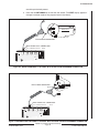
6. Sending (Loading) Records
A record can be sent (loaded) into a panel or other device. The D5203 programmer cord can
be connected directly to panels with 4-pin PROG ports and to panels which have phone jack
PROG ports.
Connecting the Programmer
New D5203 Programmer Cord Design
The D5203 programmer cord has been redesigned with a new "Y" cable that eliminates the
need for an adaptor. The new design combines the 4-pin connector plug and the phone jack
connector plug on one cord.
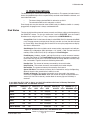
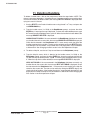
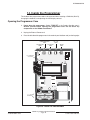
Panel with 4-Pin PROG Port
The D5200 Programmer can be connected directly to a device with a 4-pin male programming
connector (D4112, D7112, D636, and D2071 control/communicators). An example of this
type of connection is shown in Figure 20.
1. Plug the programmer cord's male phone plug into the D5200 COMMUNICATOR port.
2. Plug the D5203 programmer cord's 4-pin female connector into the 4-pin male
programming (PROG) port on the panel.
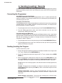
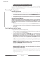
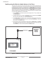
Panel with Phone Jack PROG Port
Previously, a D5206 adapter was provided with the D5200 for devices with a 4-pin female
phone jack (D6112 Control/Communicator, D8112 Control/Communicator, D6500 Receiver).
With the new cord design, the adaptor is no longer necessary An example of this type of
connection is shown in Figure 21.
1. Plug the programmer cord's male phone plug into the D5200 COMMUNICATOR port.
2. Plug the programmer cord's 4-pin male connector into the 4-pin female programming
phone jack (PROG) on the panel.
Sending (Loading) the Program
To load a record into a panel:
1. Scroll to the appropriate product handler from the Product Handlers menu using the red
↓ or ↑ keys, and press the red ENTER GROUP key.
2. Scroll to the appropriate record title using the red ↓ or ↑ keys, and press the red ENTER
GROUP key.
3. When the record title is displayed in the top line, press the red SEND (LOAD) key. The
message SENDING is displayed while the program is downloading into the device. When
the program download is complete, the message SEND SUCCESSFUL is displayed.
Plug In Device: If this message appears, check the connection from the programmer to
the device.
Tweedle: The programmer will tweedle if an attempt is made to load a panel with no
record selected. Before pressing the LOAD key, select a record title and press the red
ENTER GROUP key.
INVALID LOCK CODE: Displays if the panel lockcode does not match any of the
lockcodes programmed into the programmer. See the Lockcodes chapter for more
information.
SEND FAILURE or Comm Error: These messages are displayed if a communication
74-06176-000-B 9/95
D5200 Programmer Operation Manual
Page 27
© 1991-1995 Radionics
A-5200-030-280
error disrupts the load process.
4. Press the red EXIT GROUP key to exit from the record. (The SAVE display appears if
changes have been made to any program items in the record.)
J4
CPU
J1
BATTERY
KEY SWITCH
J4
PROGRAMMER
PROGRAMMER
J2
Radionics D7112
J2
EXPANSION
PORT
EXPANSION
PORT
D7112
4-PIN FEMALE CONNECTOR
MALE PHONE JACK CONNECTOR
D5200
D5200 COMMUNICATOR PORT
8843B
W
Aromat
DS2E-M-DC12V
0.6A 125VAC
0.6A 110VDC
2Z 30VDC
SU
Figure 20: D5203 INTERFACE TO A PANEL WITH A MOLEX PROGRAMMER CONNECTOR
M
Aromat
DS2E-M-DC12V
M
Aromat
DS2E-M-DC12V
M
MALE PHONE CONNECTOR
Aromat
DS2E-M-DC12V
M
Aromat
DS2E-M-DC12V
J2
J2
PROGRAMMER
TEST CONNECTOR
PROGRAMMER
TEST CONNECTOR
D6112
MALE PHONE JACK CONNECTOR
D5200 COMMUNICATOR PORT
D5200
8843B
W
Aromat
DS2E-M-DC12V
0.6A 125VAC
0.6A 110VDC
2Z 30VDC
SU
Figure 21:CONNECTING THE D5200 TO A PANEL WITH A PHONE JACK PROGRAMMER CONNECTOR
74-06176-000-B 9/95
D5200 Programmer Operation Manual
Page 28
© 1991-1995 Radionics
A-5200-030-280
7. Receiving (Copying) Records
A record can be copied from a control/communicator or other device into the D5200
Programmer. The D5203 programmer cord can be connected directly to panels with 4-pin
PROG ports and phone jack PROG ports.
Connecting the Programmer
Panel with 4-Pin PROG Port
The D5200 Programmer can be connected directly to a device with a 4-pin male programming
connector (D4112, D7112, D636, and D2071 control/communicators) as shown in Figure 20.
1. Plug the programmer cord's male phone plug into the D5200 COMMUNICATOR port.
2. Plug the programmer cord's 4-pin female connector into the 4-pin male programming
(PROG) port on the panel.
Panel with Phone Jack PROG Port
A D5206 adapter is no longer necessary with the D5200 for devices with a 4-pin female phone
jack (D6112 Control/Communicator, D8112 Control/Communicator, D6500 Receiver). The
new D5203 cord has a phone jack connection. An example of this type of connection is shown
in Figure 21.
1. Plug the programmer cord's male phone plug into the D5200 COMMUNICATOR port.
2. Plug the programmer cord's 4-pin female connector into the panel programming phone
jack (PROG).
Receiving (Copying) the Program
To copy a record from a panel into the programmer:
1. Scroll to the appropriate product handler from the Product Handlers menu using the red
↓ or ↑ keys, and press the red ENTER GROUP key.
2. Place the flashing cursor on a record title (or NEWRECORD). This is the record to which
the panel program will be copied. Press the red RECV (COPY) key. The message
RECEIVING is displayed while the record is uploading from the panel into the programmer.
When the record copy is complete, the message RECEIVE SUCCESSFUL is displayed.
Plug In Device: If this message appears, check the connection from the programmer to
the device, and verify that the handler of the record selected is appropriate for the device
to which the programmer is connected.
Tweedle: The programmer tweedles if an attempt is made to copy a program with no
record title (or NEWRECORD) selected by the flashing cursor.
INVALID LOCK CODE: Displays if the panel lockcode does not match any of the
lockcodes in the programmer. See the Lockcodes chapter for more information.
RECEIVE FAILURE or Comm Error: These messages are displayed if a communication error disrupts the copy process.
3. After a successful copy, the copied record is automatically entered, and module,
category, or program item titles are displayed. The copied record can be saved under a
different name, or replace the current record (see the Editing a Record section in the
Programming Records chapter).
74-06176-000-B 9/95
D5200 Programmer Operation Manual
Page 29
© 1991-1995 Radionics
A-5200-030-300
8. Passwords
Access to several functions of the D5200 can be limited through the use of passwords. Eight
passwords can be programmed in the D5200. The D5200 Programmer is shipped with no
passwords initially entered. NOTE: This feature is password dependent. If the programmer
is logged onto with a password that does not have the authority to edit passwords, the
message ACCESS DENIED is displayed when trying to access this feature.
If you forget all of the programmed passwords in your D5200, the programmer must
be returned to Radionics (with an RMA number) for reinitialization. Please state on
the RMA that you are locked out of the programmer. All data on Disk A (the internal
battery backed RAM) is erased when the programmer is reinitialized.
To program passwords and designate authority to use certain functions of the D5200:
1. Scroll to SECURITY in the Product Handlers menu using the red ↓ or ↑ keys, and press
the red ENTER GROUP key.
2. Scroll to Passwords in the SECURITY menu using the red ↓ or ↑ keys, and press the
red ENTER GROUP key. The Passwords menu is displayed.
U1Password: Enter up to 8 characters for the User 1 password, and press the white
ENTER key. The User 1 password is automatically provided access to all D5200
functions, and must be programmed before additional passwords (for User# 2 through
8) can be programmed.
User#: The remaining fields are indexed programming fields. Enter the user number (2
through 8 – the default for the first round of programming is 2), and press the white
ENTER key. The # in the U#Password field changes to match the number programmed
in the User# field.
U#Password: The # in this field name changes to the number programmed in the User#
2 Password for the first round of programming.) Enter up to 8
field. (The default is U2
characters for the User # password, and press the white ENTER key.
In the following program items, typing Y and pressing the white ENTER key enables the
function for the U#Password. An entry of N disables the function for the U#Password.
Pressing the SPACE bar toggles between Y and N.
U#PasswordEnable: Enter Y to enable the U#Password. Enter N to disable the
U#Password. If this program item is set to N, entering this password will not be accepted
as valid on programmer power-up.
U#Delete Record: Enter Y to give U#Password the authority to delete records. Enter N
to disable this function for U#Password.
U#Delete Handler: Enter Y to give U#Password the authority to delete handlers. Enter
N to disable this function for U#Password.
U#Edit Lockcodes: Enter Y to give U#Password the authority to change panel
lockcodes. Enter N to disable this function for U#Password.
U#Edit Passwords: Enter Y to give U#Password the authority to change passwords.
Enter N to disable this function for U#Password.
U#Edit Vis/Invis: Enter Y to give U#Password the authority to make program items
invisible. Enter N to disable this function for U#Password.
74-06176-000-B 9/95
D5200 Programmer Operation Manual
Page 30
© 1991-1995 Radionics
A-5200-030-300
U#Update Handler: Enter Y to give U#Password the authority to update handlers. Enter
N to disable this function for U#Password.
U#Replace Record: Enter Y to give U#Password the authority to permanently change
(replace) programmed account records. Enter N to disable this function for U#Password.
NOTE: If this function is disabled for the Password, the user will still be able to edit
records, but edited records must be saved under a different name.
U#Format Disk: Enter Y to give U#Password the authority to format disks. Enter N to
disable this function for U#Password. NOTE: Formatting a disk permanently erases all
data on the disk.
U#Lock Record: Enter Y to give U#Password the authority to lock records. Enter N to
disable this function for U#Password.
3. After an entry is made for U#Lock Record, the display wraps around to U1Password.
Press the white ENTER key or the red ↓ key to move the cursor to the User# field. Enter
a new user number and press the white ENTER key. The # in all U# program item titles
changes to match the new number programmed in the User# field. Passwords for up
to 8 users are programmed as described in Step 2. (U1Password needs to be
programmed only once, even though it scrolls into view after other U# password
parameters have been programmed. Simply scroll past it with the red ↓ key .)
4. To exit the Passwords menu, press the red EXIT GROUP key. The cursor returns to the
SECURITY menu.
5. To exit the SECURITY menu, press the red EXIT GROUP key. The cursor returns to the
Product Handlers level.
If a user attempts to access a function to which the user's password has not been given
authority, the message ACCESS DENIED is displayed.
74-06176-000-B 9/95
D5200 Programmer Operation Manual
Page 31
© 1991-1995 Radionics
A-5200-030-320
9. LockCodes
The DataLock system uses lockcodes to lock panels from programming by unauthorized
programmers. A Datalocked panel has a lockcode in memory that the 5200 must match to
one of the lockcodes in the 5200 lockcode records before the programming session can
continue. The 5200 can not match the lockcode in the panel, the programming session is
terminated.
Ram II organizes its lockcodes into four different types, default, primary, alternate, and
unaltered. See LockCode Types below.
NOTE: This feature is password dependent. If the programmer is logged onto with a
password that does not have the authority to edit lockcodes, the message ACCESS DENIED
is displayed when trying to access this feature.
1. Scroll to SECURITY in the Product Handlers menu using the red ↓ or ↑ keys, and press
the red ENTER GROUP key.
2. Use the red ↓ key to scroll down to LockCodes, and press the red ENTER GROUP key.
3. The cursor flashes in the Primary Lock data entry field. Enter a primary lockcode (from
1 to 65535) and press the white ENTER key. NOTE: Due to an internal security algorithm,
one of 255 lockcodes can result from an entry for the D4112 and D6112 control/
communicators.
4. The cursor flashes in the Lock# data entry field. Enter the number of the lockcode you
wish to program (from 1 to 50) and press the white ENTER key.
5. The cursor flashes in the Lockcode data entry field. This program item is indexed to the
Lock# entry. The number entered in Lock# will be added to the Lockcode prompt.
For example, if 2 is entered for Lock, the next prompt will be Lockcode2. Enter a
lockcode (from 1 to 65535) and press the white ENTER key. NOTE: Due to an internal
security algorithm, one of 255 lockcodes can result from an entry for the D4112 and
D6112 control/communicators.
6. The cursor flashes in the Primary Lock data entry field, which has wrapped around in
the display. Use the red ↓ key to scroll down to the Lock# prompt.
7. Enter the number of the new lockcode you wish to program and press the ENTER key.
8. The cursor flashes in the Lockcode data entry field. Enter a lockcode (from 1 to 65535)
and press the white ENTER key.
9. Repeat steps 6 through 8 until all desired lockcodes have been programmed. To return
to the SECURITY menu, press the red EXIT GROUP key. To return to the Product Handlers
level, press the red EXIT GROUP key again.
Programmer Tips – Working with Lockcodes
For panels with the datalock feature, the panel lockcode is verified when the panel is
accessed (record send or receive). There are four types of lockcodes:
•
Default Lockcode: The code 12345 is the default entry for all D5200 lockcodes.
•
Primary Lockcode: This is the lockcode programmed in the Primary Lock field.
•
Alternate Lockcode: If the lockcode in a panel matches one of the first 35 "alternate"
lockcodes (Lockcodes 1 through 35), the panel lockcode is changed to the primary
lockcode, and the message LOCK CODE SET is displayed.
•
Unaltered Lockcode: If the panel lockcode matches one of the remaining lockcodes
(36 through 50), the panel lockcode is not changed.
If the panel lockcode does not match any of the programmer lockcodes, the message
INVALID LOCK CODE is displayed, and the panel cannot be accessed.
74-06176-000-B 9/95
D5200 Programmer Operation Manual
Page 32
© 1991-1995 Radionics
A-5200-030-320
10. Updating Handlers
The update feature of the D5200 can be used to add product handlers to the programmer,
update existing programmer handlers, and copy locked records from one programmer to
another. Handlers can be added and updated via the phone lines at 300 baud using the
programmer TELCO connector, via a serial interface at 19.2k baud using the RS-232
connector, and between internal Disk A and removable RAM Disk B within the programmer
(see Figure 22). The time required to updatehandlers in a programmer depends upon the
interfaced used (see Figure 23). Since it is much quicker to update a D5200 via the RS-232
serial interface, Radionics recommends updating only the first programmer via the phone
(Telco) lines, and updating additional programmers from the first programmer via the RS232 interface.
NOTE: This feature is password dependent. If the programmer is logged onto with a
password that does not have the authority to update, the message ACCESS DENIED is
displayed when trying to access this feature.
TO
DISK A
DISK B
DISK
B->A
A->B
RADIONICS PHONE
UPDATE SYSTEM
D5200
TELCO->A
TELCO->B
SENDING
D5200 (local)
D5200
A->RS232
B->RS232
RECEIVING
D5200 (local)
D5200
RS232->A
RS232->B
SENDING
D5200 (phone)
D5200
A->TELCO
B->TELCO
RECEIVING
D5200 (phone)
D5200
TELCO->A
TELCO->B
FROM
INTERNAL DISK
Figure 22: UPDATE METHODS
PRODUCT
HANDLER
PHONE UPDATE
WITH HELP
PHONE UPDATE
WITHOUT HELP
RS-232 UPDATE
WITH HELP
RS-232 UPDATE
WITHOUT HELP
D2071
6:00
4:41
00:13
00:11
D4112
10:21
8:52
00:23
00:15
D6112
12:49
8:23
00:29
00:20
5:24
4:46
00:15
00:10
:
15:13
:
00:34
*37:00
*28:00
*1:33
*1:10
D636
D7112
D8112 SERIES
NOTE: Phone times shown above are for "clean" phone lines. Line noise can increase the update time.
* 8112 Times are best estimate at time of printing.
Data not available for blank entries.
Figure 23: UPDATE TIMES (MINUTES:SECONDS)
74-06176-000-B 9/95
D5200 Programmer Operation Manual
Page 33
© 1991-1995 Radionics
A-5200-030-340
Disk to Disk Updates
Handlers and locked records can be copied from Disk A to Disk B (and Disk B to Disk A) in
the programmer. If the "receiving" disk already has the handler to be updated, the "sending"
disk transfers only its locked records (i.e. NEWRECORD) to the "receiving" disk. If the
"receiving" disk does not currently contain the handler to be transferred, the "sending" disk
transfers the handler and all locked records (i.e. NEWRECORD) to the "receiving" disk.
1. Scroll to UPDATE in the Product Handlers menu using the red ↓ or ↑ keys, and press the
red ENTER GROUP key.
2. Type the handler name (i.e. 7112) at the Handler prompt, and press the white ENTER
key. The cursor moves down to the Include Help prompt.
3. The Include Help entry defaults to No. To include the handler help file in the update,
press the SPACE bar to toggle the entry to Yes. Press the white ENTER key. The cursor
moves down to the Phone prompt.
4. Use the red ↓ key to scroll down to the Mode prompt.
A→B
To transfer a handler from internal Disk A to the removable RAM disk B: Press the SPACE
bar until the A→B selection is displayed (see Figure 24).
B→A
To transfer a handler from removable RAM Disk B to internal Disk A: Press the SPACE
bar until the B→A selection is displayed.
5. Press the white ENTER key. If the transfer is successful, the message UPDATE
SUCCESSFUL is displayed. The cursor returns to the UPDATE menu. To copy additional
handlers, repeat steps 2 through 5.
If the transfer is not successful, the message UPDATE FAILURE is displayed. If the
specified handler does not exist on the "sending" disk", the message HANDLER NOT
FOUND is displayed.
6. To return to the Product Handlers level, press the red EXIT GROUP key.
UPDATE
Phone:
Mode: A -> B
Figure 24: DISK TO DISK HANDLER COPY
74-06176-000-B 9/95
D5200 Programmer Operation Manual
Page 34
© 1991-1995 Radionics
A-5200-030-340
Updating using the Radionics Update System via the Phone
The programmer can be set up to receive handler updates from the Radionics Update System
via the phone (pulse dialing only). If the programmer already has the handler to be updated,
the Update System transfers only its locked records (i.e. NEWRECORD) to the programmer.
If the programmer does not currently contain the handler to be transferred, the Update
System transfers the handler and all locked records (i.e. NEWRECORD) to the programmer.
Connect the programmer to the phone line (TELCO port to phone jack) as shown in Figure
25, and set up the programmer as shown below.
1. Scroll to UPDATE in the Product Handlers menu using the red ↓ or ↑ keys, and press the
red ENTER GROUP key.
2. Type the handler name (i.e. 7112) at the Handler prompt, and press the white ENTER
key. The cursor moves down to the Include Help prompt.
3. The Include Help entry defaults to No. To include the handler help file in the update,
press the SPACE bar to toggle the entry to Yes. Press the white ENTER key. The cursor
moves down to the Phone prompt.
4. Enter the phone number of the Radionics Update System, 14087577832, in the Phone
field. (Add or remove prefix information as required for dialing from your area.) Press the
white ENTER key. The cursor moves down to the Mode prompt.
PHONE NETWORK
EXTERNAL COMMUNICATOR
POWER
AUXILIARY
RS-232
RADIONICS
UPDATE
SYSTEM
TELCO
D5200
UPDATE
Phone: 14087577832
Mode: TELCO -> A
PROGRAMMER
Figure 25: CONNECTING TO THE RADIONICS UPDATE SYSTEM
74-06176-000-B 9/95
D5200 Programmer Operation Manual
Page 35
© 1991-1995 Radionics
A-5200-030-360
5. Mode prompt entry:
TELCO → A
To transfer a handler to internal Disk A: Press the SPACE bar until the TELCO→A
selection is displayed.
TELCO → B
To transfer a handler to removable RAM Disk B: Press the SPACE bar until the
TELCO→B selection is displayed.
6. Press the white ENTER key. The programmer clicks as it dials out, and the message
WAITING for CARRIER is momentarily displayed, followed by the message WAITING
for CONNECT to Update System is displayed. When this handler request is detected
by the Update System, the Update System transfers the requested handler. The
progress of the handler reception is displayed on the programmer (see Figure 26). If the
transfer is successful, the message UPDATE SUCCESSFUL is displayed. The cursor
returns to the UPDATE menu. To update additional handlers, repeat steps 2 through 6.
If the transfer is not successful, the message UPDATE FAILURE is displayed. If the
handler requested by the programmer was not available in the Update System, the
message HANDLER NOT FOUND is displayed.
7. To return to the Product Handlers level, press the red EXIT GROUP key.
RECEIVING 7112
0%
Block:xxx:
100%
Figure 26: "RECEIVING PROGRAMMER" UPDATE PROGRESS
Programmer Tip – Updating Multiple Programmers
The time required to updatehandlers in a programmer depends upon the interfaced
used (see Figure 23). Since it is much quicker to update a D5200 via the RS-232 serial
interface, Radionics recommends updating only the first programmer via the phone
(Telco) lines, and updating additional programmers from the first programmer via the
RS-232 interface (see "Updating Via RS-232" on the following pages).
74-06176-000-B 9/95
D5200 Programmer Operation Manual
Page 36
© 1991-1995 Radionics
A-5200-030-360
Updating via RS-232
Using the serial interface, handlers and locked records can be quickly transferred from one
programmer to another. One D5200 is the "Sending Programmer" of handlers and records,
and the second D5200 is the "Receiving Programmer". If the Receiving Programmer already
has the handler to be updated, the Sending Programmer transfers only its locked records (i.e.
NEWRECORD) to the Receiving Programmer. If the Receiving Programmer does not
currently contain the handler to be transferred, the Sending Programmer transfers the
handler and all locked records (i.e. NEWRECORD) to the Receiving Programmer. Connect
the two programmers together (RS-232 port to RS-232 port) with a Radionics D5204 cable
(2 feet long) as shown in Figure 27. A 25-foot cable in this configuration can be purchased
from Radio Shack (Cat. No. 279-422). To build a custom cable, purchase Radio Shack Cat.
No. 279-421. This kit consists of 10 six-pin modular connectors. (A crimping tool is required
to build a custom cable.) All six conductors are required.
SENDING PROGRAMMER – RS-232
This programmer will be sending the updated handler to the Receiving Programmer.
1. Scroll to UPDATE in the Product Handlers menu using the red ↓ or ↑ keys, and press the
red ENTER GROUP key.
2. Use the red ↓ key to scroll down to the Mode prompt.
A → RS232
To transfer a handler from internal Disk A: Press the SPACE bar until the A→RS232
selection is displayed.
B → RS232
To transfer a handler from removable RAM Disk B: Press the SPACE bar until the
B→RS232 selection is displayed.
D5204 CABLE
RS-232 PORT
1 Gnd
2 RTS
3 Tx
4 Rx
5 CTS
6 Gnd
EXTERNAL
POWER
COMMUNICATOR
AUXILIARY
RS-232
TELCO
RS-232 PORT
1 Gnd
2 RTS
3 Tx
4 Rx
5 CTS
6 Gnd
EXTERNAL
POWER
COMMUNICATOR
AUXILIARY
RS-232
D5200
TELCO
D5200
UPDATE
UPDATE
Phone:
Phone:
Mode: A -> RS232
Mode: RS232 -> A
SENDING
PROGRAMMER
RECEIVING
PROGRAMMER
Figure 27: RS-232 UPDATE CONFIGURATION
74-06176-000-B 9/95
D5200 Programmer Operation Manual
Page 37
© 1991-1995 Radionics
A-5200-030-380
3. Press the white ENTER key. The message WAITING for Handler Request... is
displayed. When the handler request from the Receiving Programmer is detected, the
Sending Programmer transfers the requested handler. The progress of the handler
transmission is displayed (see Figure 28). If the transfer is successful, the message
UPDATE SUCCESSFUL is displayed. If the transfer is not successful, the message
UPDATE FAILURE is displayed. The cursor returns to the UPDATE menu.
4. To update additional handlers, repeat steps 2 and 3. To return to the Product Handlers
level, press the red EXIT GROUP key.
SENDING 7112
0%
Block:xxx:
100%
Figure 28: SENDING PROGRAMMER UPDATE PROGRESS
RECEIVING PROGRAMMER – RS-232
This programmer will be receiving the handler update from the Sending Programmer.
1. Scroll to UPDATE in the Product Handlers menu using the red ↓ or ↑ keys, and press the
red ENTER GROUP key.
2. Type the handler name (i.e. 7112) at the Handler prompt, and press the white ENTER
key. The cursor moves down to the Include Help prompt.
3. The Include Help entry defaults to No. To include the handler help file in the update,
press the SPACE bar to toggle the entry to Yes. Press the white ENTER key. The cursor
moves down to the Phone prompt.
4. Use the red ↓ key to scroll down to the Mode prompt.
RS232 → A
To transfer a handler to internal Disk A: Press the SPACE bar until the RS232→A
selection is displayed.
RS232 → B
To transfer a handler to removable RAM Disk B: Press the SPACE bar until the
RS232→B selection is displayed.
5. Press the white ENTER key. The message WAITING for CONNECT to Update
System is displayed. When this handler request is detected by the Sending Programmer,
the Sending Programmer transfers the requested handler. The progress of the handler
reception is displayed (see Figure 26). If the transfer is successful, the message UPDATE
SUCCESSFUL is displayed. The cursor returns to the UPDATE menu. To update another
handler, repeat steps 2 through 5.
If the transfer is not successful, the message UPDATE FAILURE is displayed.
If the handler requested by the Receiving Programmer was not available in the Sending
Programmer, the message HANDLER NOT FOUND is displayed.
6. To return to the Product Handlers level, press the red EXIT GROUP key.
74-06176-000-B 9/95
D5200 Programmer Operation Manual
Page 38
© 1991-1995 Radionics
A-5200-030-380
Updating via the Phone
Handlers in one programmer can be updated by a second programmer via the phone (pulse
dialing only). One D5200 is the "Sending Programmer" of handlers and locked records, and
the second D5200 is the "Receiving Programmer". If the Receiving Programmer already has
the handler to be updated, the Sending Programmer transfers only its locked records (i.e.
NEWRECORD) to the Receiving Programmer. If the Receiving Programmer does not
currently contain the handler to be transferred, the Sending Programmer transfers the
handler and all locked records (i.e. NEWRECORD) to the Receiving Programmer. Connect
the SENDING and RECEIVING Programmers to phone lines (TELCO port to phone jack) as
shown in Figure 29, and set up each programmer as described below.
SENDING PROGRAMMER – TELCO
This programmer will be sending the updated handler to the Receiving Programmer.
1. Scroll to UPDATE in the Product Handlers menu using the red ↓ or ↑ keys, and press the
red ENTER GROUP key.
2. Use the red ↓ key to scroll down to the Mode prompt.
A → TELCO
To transfer a handler from internal Disk A: Press the SPACE bar until the A→TELCO
selection is displayed.
B → TELCO
To transfer a handler from removable RAM Disk B: Press the SPACE bar until the
B→TELCO selection is displayed.
PHONE NETWORK
SPLITTER
Necessary only if no other
ringing device on circuit.
PHONE
EXTERNAL COMMUNICATOR
POWER
AUXILIARY
RS-232
TELCO
EXTERNAL COMMUNICATOR
POWER
AUXILIARY
RS-232
D5200
UPDATE
D5200
Phone:
UPDATE
Phone: 15045551234
Mode: A -> TELCO
Mode: TELCO -> A
SENDING
PROGRAMMER
TELCO
RECEIVING
PROGRAMMER
Figure 29: TELCO UPDATE CONFIGURATION
74-06176-000-B 9/95
D5200 Programmer Operation Manual
Page 39
© 1991-1995 Radionics
A-5200-030-400
3. Wait until the phone rings, and then press the white ENTER key. The message
WAITING for Handler Request... is displayed. When the handler request from the
Receiving Programmer is detected, the Sending Programmer transfers the requested
handler at 300 baud. The progress of the handler transmission is displayed (see Figure
28). If the transfer is successful, the message UPDATE SUCCESSFUL is displayed. If the
transfer is not successful, the message UPDATE FAILURE is displayed. The cursor
returns to the UPDATE menu. To update additional handlers, repeat steps 2 and 3.
4. To return to the Product Handlers level, press the red EXIT GROUP key.
RECEIVING PROGRAMMER – TELCO
This programmer dials out and receives the handler update from the Sending Programmer.
1. Scroll to UPDATE in the Product Handlers menu using the red ↓ or ↑ keys, and press the
red ENTER GROUP key.
2. Type the handler name (i.e. 7112) at the Handler prompt, and press the white ENTER
key. The cursor moves down to the Include Help prompt.
3. The Include Help entry defaults to No. To include the handler help file in the update,
press the SPACE bar to toggle the entry to Yes. Press the white ENTER key. The cursor
moves down to the Phone prompt.
4. Enter the phone number of the Sending Programmer in the Phone field. This entry can
be up to 24 characters: 0-9, C (3 second wait), D (7 second wait), and can wrap around
to the second line under the Phone prompt. Press the white ENTER key. The cursor
moves down to the Mode prompt.
5. Mode prompt entry:
TELCO → A
To transfer a handler to internal Disk A: Press the SPACE bar until the TELCO→A
selection is displayed.
TELCO → B
To transfer a handler to removable RAM Disk B: Press the SPACE bar until the
TELCO→B selection is displayed.
6. Press the white ENTER key. The programmer clicks as it dials out, and the message
WAITING for CONNECT to Update System is displayed. When this handler request
is detected by the Sending Programmer, the Sending Programmer transfers the
requested handler. The progress of the handler reception is displayed (see Figure 26).
If the transfer is successful, the message UPDATE SUCCESSFUL is displayed. The
cursor returns to the UPDATE menu. To update additional handlers, repeat steps 2
through 6.
If the transfer is not successful, the message UPDATE FAILURE is displayed. If the
handler requested by the Receiving Programmer was not available in the Sending
Programmer, the message HANDLER NOT FOUND is displayed.
7. To return to the Product Handlers level, press the red EXIT GROUP key.
74-06176-000-B 9/95
D5200 Programmer Operation Manual
Page 40
© 1991-1995 Radionics
A-5200-030-400
11. Deleting Handlers
To delete a handler from a disk on the programmer, follow the steps below. NOTE: This
feature is password dependent . If the programmer is logged onto with a password that does
not have the authority to delete handlers, the message ACCESS DENIED is displayed when
trying to access this feature.
1. Scroll to DELETE in the Product Handlers menu using the red ↓ or ↑ keys, and press the
red ENTER GROUP key.
2. Type the handler name (i.e. 7112) at the HandName prompt, and press the white
ENTER key. A warning message is displayed. To abort the handler delete process, type
N. To continue with the delete process, press Y. When the handler has been deleted, the
message HANDLER DELETED is displayed.
HANDLER NOT FOUND: If the name entered in the HandName field does not match
any handler titles on the current disk, the message HANDLER NOT FOUND is displayed.
Check the title entered in the HandName field – it must exactly match the title of the
handler stored on the current disk. The title can be verified by exiting the DELETE display
and viewing the list of handlers. If the handler title is not displayed, it may be stored on
a different disk. See Changing the Disk section in the Disk Operations chapter.
3. To delete a help file, use the red ↓ key to scroll down to the HelpName prompt.
4. Type the help file name, which is identical to the handler name (i.e. 7112) at the
HelpName prompt, and press the white ENTER key. A warning message is displayed.
To abort the help file delete process, type N. To continue with the delete process, press
Y. When the help file has been deleted, the message HELP DELETED is displayed.
HELP NOT FOUND: If the name entered in the HelpName field does not match any
handler titles on the current disk, the message HELP NOT FOUND is displayed. Check
the title entered in the HelpName field – it must exactly match the title of the help file
stored on the current disk. The title can be verified by exiting the DELETE display and
viewing the list of handlers. If the handler title which is associated with the help file is not
displayed, the handler and help file may be stored on a different disk. See Changing the
Disk section in the Disk Operations chapter.
74-06176-000-B 9/95
D5200 Programmer Operation Manual
Page 41
© 1991-1995 Radionics
A-5200-030-420
5. To return to the Product Handlers level, press the red EXIT GROUP key.
12. Programmer Time Out
The D5200 Programmer is equipped with a power-saving timeout feature – the D5200
automatically powers down if no keys have been pressed within a programmed amount of
time. Follow the steps below to program the timeout.
1. Scroll to SECURITY in the Product Handlers menu using the red ↓ or ↑ keys, and press
the red ENTER GROUP key.
2. Scroll to Time Out in the SECURITY menu using the red ↓ or ↑ keys. Enter the desired
timeout value (from 02 to 10 minutes) and press the white ENTER key.
3. To exit the SECURITY menu, press the red EXIT GROUP key. The cursor returns to the
Product Handlers level.
Records Open When TimeOut Occurs
One minute before the D5200 goes into TimeOut power-down, the programmer emits a
"buzz", and the message 59 SEC TO POWER DOWN is displayed. The programmer "counts
down" until the time programmed in Time Out has expired. If a record is still open when the
D5200 Programmer goes into a power-down timeout, the record is saved under the title
TIMEOUTSAVE. One TIMEOUTSAVE record can be saved per handler. If a TIMEOUTSAVE
record already exists for a particular handler, the new TIMEOUTSAVE record will overwrite
the old TIMEOUTSAVE record.
When the programmer is switched on and the handler is entered, the programmer emits a
"buzz" tone, and the words SAVE TIMEOUT RECORD appear among the items in the
display. Press the red ↓ key to scroll to the TIMEOUTSAVE record. The TIMEOUTSAVE
record can be opened, saved under a different title, and deleted like other records (see Editing
a Record, Copying a Record, and Deleting a Record in the Programming Records chapter).
74-06176-000-B 9/95
D5200 Programmer Operation Manual
Page 42
© 1991-1995 Radionics
A-5200-030-420
13. Help Screens
Help screens can be accessed from almost all prompts displayed on the D5200. Help screens
are also available for individual product handler program items. Product handler help screens
can be installed when updating the handler (see the Updating Handlers chapter).
Accessing Help Screens
1. To view the help screen for a particular item, move the cursor to the item and press the
red HELP key.
If there is no help screen for a particular program item or prompt, or the help file for a
particular handler has not been loaded, the message NO HELP AVAILABLE is
displayed.
2. The item is displayed in the top line, and the help screen is displayed below. Use the red
↑ and ↓ keys to scroll through the help screen.
3. Data can be entered in program item help screen. When the white ENTER key is pressed,
the cursor exits the help screen and flashes on the next program item.
4. The help screen can be exited by pressing the red HELP key. The red EXIT GROUP, ENTER
GROUP, RECV, and SEND keys can also be used to exit help screens, provided that
pressing the particular key is an appropriate action for the item displayed in the help
screen.
74-06176-000-B 9/95
D5200 Programmer Operation Manual
Page 43
© 1991-1995 Radionics
A-5200-030-440
14. Inside the Programmer
The inside of the programmer needs to be accessed when inserting a RAM disk (Disk B),
changing the batteries, and adjusting the LCD display contrast.
Opening the Programmer Case
1. Power down the programmer. (Select 5200 OFF in the Product Handler menu.)
Ground yourself before opening the programmer case. Do not touch any
components on the D5200 circuit board.
2. Unplug the External Power cord.
3. Place the left side of the programmer in the crook of your left elbow and jam the fingertips
COMMUNICATOR
RS - 232
PORT
PORT
AC ADAPTER
AUXILIARY
PORT
PORT
J6
J1
J7
J3
TELCO
PORT
J4
LCD CONTRAST P2
ADJUSTER
W
8843B
Aromat
DS2E-M-DC12V
0.6A 125VAC
0.6A 110VDC
2Z 30VDC
SU
R98
P1
U3
J14
J12
J11
U1
J5
RAM CARD SLOT
4 "C" CELL
BATTERIES
SIZE C
BATTERY
SIZE C
BATTERY
SIZE C
BATTERY
SIZE C
BATTERY
Figure 30: INSIDE THE PROGRAMMER
74-06176-000-B 9/95
D5200 Programmer Operation Manual
Page 44
© 1991-1995 Radionics
A-5200-030-440
of both hands in the flared handle of the case. Pull the front of the case out and away from
the back – enough to clear the two metal latching pins.
Inserting a RAM Card (Disk B)
1. Power down the programmer before installing a RAM card. (Select 5200 OFF in the
Product Handler menu.) RAM cards are not hot pluggable. Inserting a RAM card with the
programmer powered up may result in damage to disk data and system software.
2. Unplug the External Power cord and open the programmer case as described on the
previous page.
3. One end of the RAM card has a shiny metallic strip, and the other end has a write-protect
switch. Insert the metallic-strip end of the RAM card into the RAM card slot (see Figure
28) with the shiny metallic strip facing down.
WARNING: Do not touch the RAM card connector assembly! Static discharge can
damage or destroy programmer components and data stored in programmer memory. An
error message will be displayed on power-up if programmer components have been
damaged.
To Remove a RAM Card:
1. Power down the programmer before removing a RAM card. (Select 5200 OFF in the
Product Handler menu.) RAM cards are not hot unpluggable. Removing a RAM card with
the programmer powered up may result in damage to disk data and system software.
2. Unplug the External Power cord and open the programmer case as described on the
previous page.
3. Grasp the RAM card from its sides, and gently ease it out of the socket.
To Write-Protect a RAM Card:
With the card plugged into the programmer, move the write-protect strip to the left position.
To Replace the RAM Card Battery:
Leave the RAM card plugged into the programmer. If the RAM disk does not have a
source of power (i.e. from the programmer) when the battery is removed, all data on
the disk will be erased.
Locate the tiny slot for removing the RAM card battery (in the black plastic edge near the writeprotect switch). Insert the end of a small screwdriver into the tiny slot and pry out the battery
holder. Replace the battery, inserting the new battery + side up as marked on the battery
holder. Insert the battery holder back into the RAM card battery + side up.
Changing the Batteries
When the message LOW BATTERY is displayed, it is time to replace the four alkaline C cell
batteries. Simply open the programmer case as described above, take out the four old
batteries, and install new ones. Proper battery direction is pictured on the base of the battery
holder (beneath the batteries). NOTE: The D5200 does not recharge the batteries. Tests
conducted by Radionics have indicated that the programmer can operate on high-quality
alkaline batteries (with no other power source) for 8 hours of continuous use. Rechargeable
batteries may provide only 1/2 the life of high quality non-rechargeable alkaline batteries.
74-06176-000-B 9/95
D5200 Programmer Operation Manual
Page 45
© 1991-1995 Radionics
A-5200-030-460
Adjusting the LCD Display Contrast
With a small screwdriver, turn the LCD contrast screw clockwise to increase display contrast,
or counterclockwise to decrease contrast. Test the contrast setting by holding down a repeat
key (i.e. scroll the display with the red ↓ key). If the contrast is set incorrectly, the display may
blur when scrolled quickly.
15. Troubleshooting Guide
This chapter contains a list of warning messages that can be displayed on the programmer,
and general programmer problems.
Programmer Problems
LCD Display Blank
If the LCD display is blank, but the programmer is emitting normal operating
sounds (tweedle, pip, etc.), turn the LCD contrast adjuster located next to the
display on the inside of the programmer.
Warning Messages
59 SEC TO POWER DOWN
The D5200 automatically powers down if no keys have been pressed within the
time programmed in Time Out (SECURITY menu). To prevent the programmer
from powering down, press any key (an arrow key is recommended, since it
will not change data or levels).
ACCESS DENIED
The password used to log on to the programmer has not been given the authority
to access the function.
BAD DATABASE FILE
This message is displayed if an attempt was made to copy a record to a disk that
does not contain the associated product handler.
LOW BATTERY
This message is displayed approximately one hour prior to low-battery power
down. This message is displayed every 10 minutes until shut down. When this
message is displayed, save the record that is currently open, power-down the
programmer, and replace the batteries. NOTE: Powering up a programmer with
a low battery condition may drain the batteries in less than one hour, depending
upon the quality of the batteries.
**BAD SYSTEM FILE *
Press any key to
default SYSTEM FILE
This message is displayed when the D5200 system file has been damaged.
Press any key to configure the D5200 with a new system file. All passwords
and lockcodes are lost when a new system file is installed, and the programmer
can only be accessed with the default all blank password (simply press the white
ENTER key). Reprogram all passwords and lockcodes (SECURITY menu).
NOTE: This message signifies an unusual event. If this message is displayed,
consider returning the unit to Radionics for repair.
Comm Error
Displayed if a communication error disrupts a send (load) or receive (copy)
process.
DISK A (or B) BAD
FORMAT IMMEDIATELY
Press any key
This message is displayed when the internal RAM disk (Disk A) or RAM Card
(Disk B) has been damaged. Press any key to access the PRODUCT HANDLERS
menu. Format the disk (FormatDisk in the SECURITY menu) as soon as
possible. NOTE: This message signifies an unusual event. If this message is
displayed, consider returning the unit to Radionics for repair.
74-06176-000-B 9/95
D5200 Programmer Operation Manual
Page 46
© 1991-1995 Radionics
A-5200-030-460
HANDLER NOT FOUND
This message is displayed if the handler requested by the Receiving Programmer during an update was not available in the Sending Programmer, or the
handler was not found on the current disk when attempting to delete the handler.
HELP NOT FOUND
This message is displayed if the help file requested by the Receiving Programmer during an update was not available in the Sending Programmer, or the help
file was not found on the current disk when attempting to delete the help file.
This message is displayed if the panel lockcode does not match any of the
lockcodes programmed into the programmer. See the Lockcodes chapter for
more information.
INVALID LOCK CODE
NO HELP AVAILABLE
There is no help screen for the particular program item or prompt selected, or the
help file for a particular handler has not been loaded.
Plug In Device
If this message appears during a send (load) or receive (copy), check the
connection from the programmer to the device. Verify that one end of the
programmer cord is plugged into the D5200 Programmer cord, and the other end
is plugged into the device (panel, etc.).
RAM CARD NOT PRESENT
This message is displayed if Disk B was selected and the RAM card is not
plugged into the programmer.
RAM DISK PROTECTED
This message is displayed if Disk B was selected and the RAM card in the
programmer is write-protected.
READ ONLY RECORD
This message is displayed if the record you are trying to replace or delete is
locked. Changes to a locked record can be saved only under a different name.
RECEIVE FAILURE
This message is displayed if a communication error disrupts a copy process.
RECORD EXISTS
This message is displayed if you are attempting to save a copied record under
a name which has already been given to a record on the current disk. Type in a
different title for the new file.
RECORD NOT DELETED
This message is displayed if the record you are trying to delete is the last record
in the specific product handler database. The last record of each product handler
cannot be deleted.
RECORD NOT FOUND
The record name entered does not match any record titles on the current disk.
The title must exactly match the title of a record stored on the current disk. If the
record title is not displayed, it may be stored on a different disk. See Changing
the Disk section in the Disk Operations chapter.
RECORD NOT REPLACED
This message is displayed if the name entered in a REPLACE display does not
match any record titles on the current disk. Check the title entered in the NAME
field – it must exactly match the title of the record stored on the current disk.
SEND FAILURE
This message is displayed if a communication error disrupts a load process.
UPDATE FAILURE
This message is displayed if a handler transfer (RS-232 to RS-232 or TELCO to
TELCO) is not successful.
74-06176-000-B 9/95
D5200 Programmer Operation Manual
Page 47
© 1991-1995 Radionics
A-5200-030-480
D5200 Security Utility
Passwords and Lockcodes Record Sheet
Make additional copies of this blank form before marking on it.
You may need to make changes when updating the programmer.
Passwords
PROMPT & DEFAULT
ENTRY
ENTRY
ENTRY
ENTRY
ENTRY
ENTRY
ENTRY
2
3
4
5
6
7
8
ENTRY
ENTRY
ENTRY
ENTRY
ENTRY
ENTRY
ENTRY
1
2
3
4
5
6
7
8
9
10
11
12
13
14
15
16
17
18
19
20
21
22
23
24
25
26
27
28
29
30
31
32
33
34
35
36
37
38
39
40
41
42
43
44
45
46
47
48
49
50
U1Password
User#:
2
U#Password
U#PasswordEnable No
U#Delete Record
No
U#Delete Handler
No
U#Edit Lockcodes
No
U#Edit Passwords
No
U#Edit Vis/Invis
No
U#Update Handler
No
U#Replace Record
No
U#Format Disk
No
U#Lock Record
No
Lockcodes
PROMPT & DEFAULT
Primary Lock:
12345
Lock#:
Lockcode:
1
12345
Lock#:
Lockcode:
Lock#:
Lockcode:
Lock#:
Lockcode:
Lock#:
Lockcode:
Lock#:
Lockcode:
Lock#:
Lockcode:
74-06176-000-B 9/95
D5200 Programmer Operation Manual
Page 48
© 1991-1995 Radionics
A-5200-030-480
74-06176-000-B 9/95
D5200 Programmer Operation Manual
Page 49
© 1991-1995 Radionics
Product
Handler
2071
4112
6112
636
7112
8112
Series
B
Space Allotted
by Operating
System (O/S)
C
Max. No. of
Records for
O/S Space
D
Space Required
for Records
(A/C) x B
↑ round up to
nearest whole number
E
Handler Size
(make entry for
each one used)
H
Total Space Required
for Handlers:
F
Help File Size
(make entry for
each one used)
J
Total Space Required
for Help Files:
Radionics D5200 Programmer – Memory Worksheet
A
Number of
records saved
(or expected
to be saved)
Make additional copies of this blank form before marking on it.
You may need to make changes when updating the programmer.
G
Total Space
Required
for Records:
Total Memory Required (G + H + J):
To fill out this worksheet, reference page number 10, Figure 4. (Total must NOT exceed disk capacity.)