1
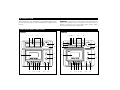
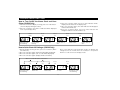
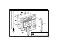
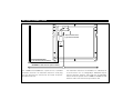
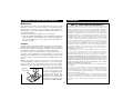
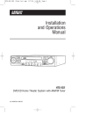
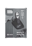
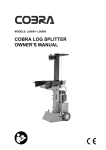
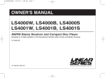
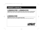
OWNER'S MANUAL
LS6000, LS6300
AM/FM Stereo Receiver and Auto Stop Cassette Player
Designed for In-Wall Installation of All Recreational Vehicles, Motor Homes and Mobile Housings
12 Volts DC
®
A Registered Trademark of Magnadyne Corporation
INTRODUCTION
Please read all of the information in this booklet before using
this unit to insure that you fully understand the capabilities of
this unit.
WARNING! To prevent fire or electrical shock hazard, do not
expose this product to rain or moisture, or remove cover or
bottom screws. No user serviceable parts inside. Refer
servicing to qualified service personnel.
CONTROLS AND FUNCTIONS
LS6000
LS6300
1
11
15
19 20 11
3
15
3
TUNING
TUNING
LS6100
AM
540
FM
88
600 700
92
96
800
1000
100
1200
1400
104
1600
108
17
18
KHZ
4
MHZ
STEREO
CD IN
ON / OFF
SPEAKER A
SPEAKER B
1
16
Time / Date
Light
AM
540
FM
88
600 700
92
96
800
1000
100
1200
1400
104
Set
Mode
1600
108
KHZ
4
MHZ
STEREO
CD In
ON/OFF
SPEAKER B
SPEAKER A
FUNCTION
FUNCTION
VOLUME
AM
5
FM
®
LS6300
AM
FM
AUX
AUX
LOW
2
HIGH
2
5
GRAPHIC EQUALIZER
VOLUME
+12
VOLUME
+12
+6
+6
0
0
-6
-6
14
14
LOW
PLAY
REW
F.F.
STOP/
EJECT
-12 LOW
PAUSE
HIGH
-12
100Hz
AM
TONE
1kHz
FM
PLAY
10kHz
REW
F.F.
STOP/
EJECT
TONE
AUX
BALANCE
BALANCE
H
L
H
L
BALANCE
L
HIGH
PAUSE
L
R
R
PHONES
L
6
7 8
9
10
16
12
R
13
6
2
7
8
9 10
12
13
CONTROLS AND FUNCTIONS
1. On / Off Button
Press this button in to turn the unit on. Press again to turn the
unit off.
9. Stop / Eject Button
When this button is pressed, tape play will stop and the
cassette carriage door will open to allow you to remove the
tape.
2. AM / FM / AUX Function Knob
After turning the unit on, select the desired playing mode with
this knob.
10. Pause Button
Pressing this button will stop the tape until the button is
released.
3. FM Stereo Indicator Light
When the tuner is receiving a strong stereo FM signal, the
stereo light will be lit.
11. Dial Indicator
The dial indicator will move up and down the scale as you
rotate the tuning knob (4) indicating the station you are
listening to.
4. Radio Station Tuning Knob
Rotate this knob to locate the radio station that you desire.
Rotating it clockwise will take you up the frequency band and
rotating it counter-clockwise will take you down the frequency
band.
12. Tone Control Knob
This control will tailor the overall tone of the unit. Rotate this
control clockwise for a higher tone and counter-clockwise
for a lower tone.
5. Cassette Carriage Door
By pressing the cassette stop / eject button (9) the door will
open to allow you to insert a tape.
13. Balance Control Knob
Rotating this knob from left to right will allow you to balance
the sound to suit your taste.
6. Play Button
After inserting a cassette tape press this button to begin tape
play.
14. Volume Control Knob
Rotate this knob to increase the volume of the unit.
7. Fast Rewind Button
To fast rewind the tape, press this button until it locks. To
release the button press the stop / eject button.
15. Speaker A / B Selector Buttons
To play the "A" set of speakers, press the "Speaker A"
button. To play the "B" set of speakers, press the "Speaker
B" button. To play the "A" and "B" speakers at the same
time, press both buttons in.
8. Fast Forward Button
To fast forward the tape, press this button until it locks. To
release the button press the stop / eject button.
3
CONTROLS AND FUNCTIONS
16. CD Input
Plug one end of a CD jumper cable into this receptacle and
plug the other end into the "line out" receptacle or
"headphone" receptacle of your portable CD player
FM Stereo Operation
The unit will automatically switch from FM mono to FM stereo
when the signal strength increases to a stereo level. If the signal
should become weak on stereo reception, the unit will switch
back to the mono mode.
It is strongly recommended to use the "line out" receptacle
of the portable CD player. The LS6000 and LS6300's
volume, balance and tone controls will operate normally
when the CD input is used
Note: Stereo operation is indicated by the stereo light (3) on the
front of the unit.
Tape Operation
17. Digital Display Clock (LS6300 Only)
This area displays the time. See the operations section of
this manual for further information.
1. Press the on / off button (1) to turn the unit on.
2. Press the stop / eject button (9) to open the cassette door.
3. Insert a cassette tape in the cassette carriage with the tape
opening down and the programs you want to listen to facing
you. Close the tape carriage door.
4. Press the play button (6).
5. To stop the tape play, press the eject button (9) once.
6. To release the tape carriage door and eject the tape, press
the stop / eject button (9) again and the door will open.
18. Clock Illumination Button (LS6300 Only)
Pressing this button will illuminate the digital display clock
and will go off automatically when the button is not being
pressed.
19. Clock Mode Button (LS6300 Only)
This button is used to set the clock, date, alarm and hour
chime. See the operations section of this manual for further
information.
Fast Forward and Fast Rewind
To fast forward or rewind a tape, press the fast forward button
( ) or the rewind button ( ) until it locks. To release the
button, press the stop / eject button () once. To resume normal
play, press the play button ( ).
20. Clock Set Button (LS6300 Only)
This button is used to adjust the time, day / date, alarm time
and hour chime. See the operations section of this manual
for further information.
AUX Operation
1. Set function knob (2) to the AUX position.
2. Turn on the item connected to the AUX inputs.
3. The volume, tone and balance controls will operate normally.
Radio Operation
1. Press the on / off button (1) in to turn the unit on.
2. Use the function knob (2) to select the AM or FM radio band.
3. Tune in the desired radio station by rotating the tuning knob
(4).
4. Adjust the volume, balance and tone controls as desired.
4
CONTROLS AND FUNCTIONS
How to Set the Date and Time (LS6300 Only)
1. With the normal time display showing, press the mode button 4
times. (The month will display)
2. Press the set button until the correct month appears.
3. Press the mode button again. (The day will display)
4. Press the set button until the correct day of the week is
displayed.
5. Press the mode button. (The hours will be displayed)
6. Press the set button until the correct hour is displayed making
sure to set AM or PM correctly. (This clock also has a 24 hour
function) A=AM, P=PM and H=24 hour clock)
7. Press the mode button. (The minutes will be displayed)
8. Press the set button until the correct minutes are shown.
9. Press the mode button once more to return to a normal
display.
Press Mode
4 Times
Press
Mode
Press
Mode
Press
Mode
Press
Mode
➧
➧
➧
➧
➧
Normal time with
colon blinking.
Minutes will display.
Depress Set to
set the minutes.
Hour will display.
Depress Set to
set the hour.
Day will display.
Depress Set to
set the day.
Month will display.
Depress Set to
set the month.
Resume normal
time display.
How to Set the Alarm (LS6300 Only)
4. Press the mode button. (The minutes will be blinking)
5. Press the set button to adjust the minutes.
6. Press the mode button. (The display will return to normal time
and "AL" will disappear from the display)
1. With the normal time display showing, press the mode button.
(The time will be blinking and "AL" will be displayed)
2. Press the mode button again. (The alarm hour will be blinking)
3. Press the set button to adjust the hour and AM , PM or H.
Press
Mode
➧
Normal time with
colon blinking.
Press
Mode
AL
Hour / minute
blinking.
➧
Press
Mode
AL
Press
Mode
➧
Hour will blink.
Depress Set button
to set desired time.
AL
Minute will blink.
Depress Set button
to set desired time.
5
➧
Normal time will
resume with colon
blinking.
CONTROLS AND FUNCTIONS
How to Turn On/Off the Alarm Clock and Hour
Chime (LS6300 Only)
3. Press the set button again. (The hour chime indicator will be
displayed at the button of the display area)
4. Press the set button again. (The alarm indicator will disappear
and the alarm will be off)
5. Press the set button again. (The hour chime indicator will
disappear and the hour chime will be off)
1. With the normal time display showing, press the mode button.
(The time display will begin to flash)
2. Press the set button. (The alarm on indicator will be displayed
at the top the display area)
Press
Mode
➧
Normal time with
colon blinking.
Press
Set
AL
Press
Set
➧
Hour / minute
blinking.
➧
AL
Alarm is ON.
Press
Set
Press
Set
AL
➧
Hourly chime is
ON.
AL
Alarm is OFF.
➧
AL
Hourly chime is
OFF.
How to Quick Check All Settings: (LS6300 Only)
Note: In the alarm time and month / day modes, the display will
change back to the normal time if the set button is not pushed
within 2 seconds of these two display modes.
1. With the display showing the time, press the set button. (Alarm
time will show)
2. Press the set button again. (Month and day will be displayed)
3. Press the set button again. (The seconds will be displayed)
4. Press the set button again. (Display will be normal time)
After 2 seconds will return to normal time
Press
Set
➧
Normal time with
colon blinking.
AL
Alarm Time
Press
Set
Press
Set
Press
Set
➧
➧
➧
Month / Day.
Seconds
6
Normal time with
colon blinking.
INSTALLATION
Wall Panel
ING
TUN
AM
54 0
88
70 0
96
60 0
92
80 0
10 00
1200
10 4
1600
1400 8
10
KHZ
MHZ
CD
10 0
IN
EO
STER
FM
®
LS6
000
SPE
AK
SPE
ON
ER
AKE
RB
RAD
A
AN
IO B
FM
D
AUX
AM
F
/OF
VOL
UM
E
HIGH
End Caps
LOW
OP
O ST
AUT
E
ANC
BAL
ORT
NSP
TRA
CT
E JE
FT
/ SO
P/
TOR
STOCT
MO
VO
E JE
SER
.
DC
F.F
RE W
E
TON
SE
PAU
R
HIG
H
L
LO W
Y
PL A
Structural
Stud
!
7
Caution: Do not install radio without rear
cover installed. No user-serviceable parts
inside. Rear cover provides protection
against potential fire hazard.
POWER / AUX CONNECTIONS
This unit for use only with a 12 volt DC power
source with a negative ground.
8
SPEAKER CONNECTIONS
Left Speaker (A)
Right Speaker (A)
+
+
_
_
BROWN Wire
GRAY Wire
ORANGE Wire
WHITE Wire
_
_
GREEN Wire
BLUE Wire
+
Left Speaker (B)
+
Speaker Connections: Do not confuse the A and B speaker sets
9
Right Speaker (B)
ANTENNA CONNECTIONS
External Automotive
Type Antenna Socket
Either
or
External Automotive
Type Antenna (Not Provided)
DP36AXT In-Wall Antenna (Not Provided)
If an automotive antenna is not available or is undesired, we
recommend the use of a Magnadyne DP36AXT di-pole
antenna substitute. Plug the male plug from the DP36AXT
into the female receptacle of the LS6000 or LS6300 unit and
allow the cable of the antenna to lay inside the wall.
The LS6000 and LS6300 have a provision for a standard
automotive antenna. If an automotive antenna is used, plug
the male plug from the antenna into the female receptacle
provided on the unit.
10
SAFETY INSTRUCTIONS
Read Instructions: All the safety and operating instructions should be
read before the appliance is operated.
Damage Requiring Service: The appliance should be serviced by
qualified service personnel when:
A. The power supply cord or the plug has been damaged; or
B. Objects have fallen, or liquid has spilled into the appliance; or
C. The appliance has been exposed to rain; or
D. The appliance does not appear to operate normally or exhibits a
marked change in performance; or
E. The appliance has been dropped, or the enclosure damaged.
Retain Instructions: The safety and operating instructions should be
retained for future reference.
Heed Warnings: All warnings on the appliance and in the operating
instructions should be adhered to.
Follow Instructions: All operating and use instructions should be
followed.
Servicing: The user should not attempt to service the appliance
beyond that described in the operating instructions. All other servicing
should be referred to qualified service personnel.
Water and Moisture: The appliance should not be used near water-for example, near a bathtub, washbowl, kitchen sink, laundry tub, in a
wet basement, or near a swimming pool, etc.
Example of Antenna Grounding as per
National Electrical Code. Instructions
Contained in Artical 810-"Radio and
Television Equipment"
Wall or Ceiling Mounting: The appliance should be mounted to a wall
or ceiling only recommended by the manufacturer.
Heat: The appliance should be situated away from heat sources such
as radiators, heat registers, stoves, or other appliances (including
amplifiers) that produce heat.
Antenna Lead-In Wire (B)
Power Supply: The appliance should be connected to a power supply
only of the type described in the operating instructions or as marked on
the appliance.
Mast
Ground
Clamp
Cleaning: The appliance should be cleaned only as recommended by
the manufacturer.
Ground
Wire
(A,B)
Power Lines: An outdoor antenna should be located away from power
lines.
Outdoor Antenna Grounding: If an outside antenna is connected to
the receiver, be sure the antenna system is grounded so as to provide
some protection against voltage surges and built up static charges.
Section 810 of the National Electrical Code, ANSI/NFPS no. 70-1983,
provides information with respect to proper grounding of the mast and
supporting structure, grounding of the lead-in wire to an antenna
discharge unit, size of grounding conductors, location of antennadischarge unit, connection to grounding electrodes, and requirements
for the grounding electrode. See figure 1.
Object and Liquid Entry: Care should be taken so that objects do not
fall and liquids are not spilled into the enclosure through openings.
Antenna Discharge
Unit (C)
To Receiver
Grounding
Clamps
Figure 1.
2.44 Meters
11
Grounding Electrode
Drivin 8' Into the Earth
A) Use No. 10 AWG (5.3mm2) copper, No 8 AWG (8.4mm2) aluminum, No. 17
AWG (1.0mm2) copper clad steel or bronze wire, or larger, as ground wire.
B) Secure antenna lead-in and ground wires to house with stand-off insulators
spaced from 4 feet (1.22m) to 6 feet (1.83m) apart.
C) Mount antenna discharge unit as close as possible to where lead-in enters
house.
OPERATION AND MAINTENANCE
WARRANTY
Maintenance
ONE (1) YEAR LIMITED WARRANTY
The playback head is a very important part of the tape
playback system. If it becomes dirty, the sound quality will
deteriorate resulting is loss of fidelity (high frequency
reproduction). The head should be cleaned every 20 hours of
use. (Approximately)
1. Press the eject button and open the cassette door.
2. Clean the playback head with a cotton applicator (Q-tip) and
alcohol. Soak the cotton applicator in the alcohol and rub the
face of the head until it is clean. Never use sharp objects to
perform cleaning.
Magnadyne Corporation or its authorized agents will within 1 year from the
date of sale to you, repair, replace or refund the retail sales price of said
product or any part thereof, at the option of the Magnadyne Corporation or
its authorized agents, if said product or part is found defective in materials or
workmanship, when properly connected and operating on the correct power
requirements designated for the specific product. This warranty and
Magnadyne Corporation or its authorized agents obligations hereunder do
not apply where the product was; damaged while in the possession of the
consumer, subjected to unreasonable or unintended use, not reasonably
maintained, utilized in commercial or industrial operations, or serviced by
anyone other than Magnadyne Corporation or its authorized agents, or
where the warning seal on the product is broken or the power and/or plugs
are detached from the unit. Magnadyne Corporation or any of its authorized
agents will not assume any labor costs for the removal and re-installation of
any product found to be defective, or the cost of transportation to
Magnadyne Corporation or its authorized agents. Such costs are the sole
responsibility of the purchaser.
This warranty does not cover the cabinet appearance items or accessories
used in connection with this product, or any damaged to recording or
recording tape, or any damage to the to the products resulting from
improper installation, alteration, accident, misuse, abuse or acts of nature.
MAGNADYNE CORPORATION OR ITS AUTHORIZED AGENTS SHALL NOT
BE LIABLE TO ANYONE FOR CONSEQUENTIAL OR INCIDENTAL
DAMAGES OR CLAIMS EXCEPT THOSE ACCORDED BY LAW. NO
EXPRESSED WARRANTY OR IMPLIED WARRANTY IS GIVEN EXCEPT
THOSE SET FORTH HEREIN. NO IMPLIED WARRANTY SHALL EXTEND
BEYOND 1 YEAR FROM THE DATE OF SALE.
This warranty extends only to the original purchaser of the product and is not
transferable.
Some states do not allow limitations on how long an implied warranty lasts,
and some states do not allow the exclusion or limitation of incidental or
consequential damages, so the above limitations or exclusion may not apply
to you. This warranty gives you specific legal rights, and you may have other
rights that vary from state to state.
Defective merchandise should be returned to the original point of purchase
or secondly, to Magnadyne Corporation, 1111 W. Victoria Street, Compton
CA 90220, or 2061 Cohen Street, Montreal, Quebec H4R 2N7. Return
Authorization must be obtained before sending, or merchandise may be
refused.
Caution:
Cassette tape should be stored in a container or vinyl bag to
prevent contamination by moisture and dust. Tapes should not
be placed in locations exposed to sunlight or in the vicinity of
any magnetic field such as televisions or stereo speakers.
Be sure and eject the tape before turning off the unit. If a
cassette is left engaged in the mechanism. a flat spot will
develop from the pressure of the capstan and pinch roller, thus
causing uneven sound reproduction and damage to your
tapes.
Before inserting a cassette into the unit, look through the
cassette window to make sure that there is no excess slack,
several loose turns. If necessary, insert a pencil or similar
object in the reel hub (figure A) and rotate it to take up the
slack, If a poor quality tape
Figure A
or a 120 minute tape is used
in this unit the tape may
Loose Tape
become entangled with the
capstan and break. We
recommend no longer than
90 minute, good quality
brand name cassettes be
used in the LS6000 / LS6300.
12