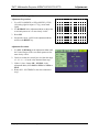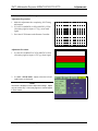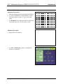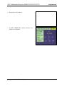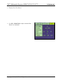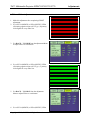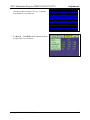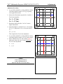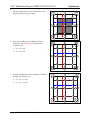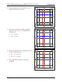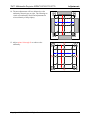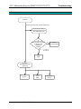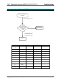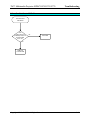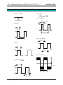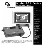
1
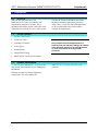
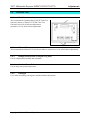
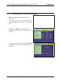
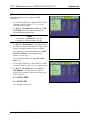
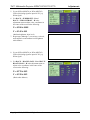
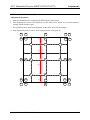
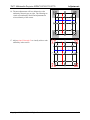
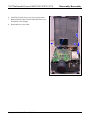
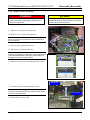
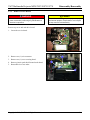
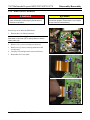
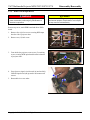
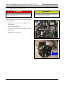
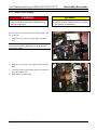
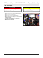
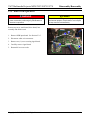
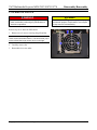
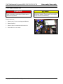
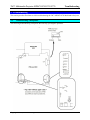
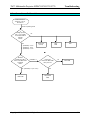
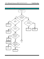
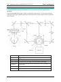
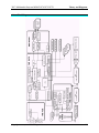
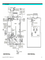
Service Manual MP8670/8745/8755/8770 Multimedia Projector Warranty and Limited Remedy. This product will be free from defects in material and manufacture for a period of two years from the date of purchase. 3M MAKES NO OTHER WARRANTIES INCLUDING, BUT NOT LIMITED TO, ANY IMPLIED WARRANTY OF MERCHANTABILITY OR FITNESS FOR A PARTICULAR PURPOSE. If this product is defective within the warranty period stated above, your exclusive remedy shall be, at 3M’s option, to replace or repair the 3M product or refund the purchase price of the 3M product. _______________________________________________________________ Limitation of Liability. Except where prohibited by law, 3M will not be liable for any loss or damage arising from this 3M product, whether direct, indirect, special, incidental or consequential regardless of the legal theory asserted. 3M Visual Systems Division 6801 River Place Boulevard Austin, Texas 78726-9000 E. P. S. Service Documentation Copyright © 2000, 3M IPC. All Rights Reserved. 78-6970-8985-8 MP8670/8745/8755/8770 Table of Contents SECTION 1 ADJUSTMENTS 1-1 Adjustments ................................................................................................................................................ 1-1 1-2 Section Contents ......................................................................................................................................... 1-1 1-3 Machine Identification ................................................................................................................................ 1-1 1-4 Technical Tools........................................................................................................................................... 1-2 1-5 Cleaning LCD Panels.................................................................................................................................. 1-3 1-6 Convergence................................................................................................................................................ 1-4 1-7 White Balance ............................................................................................................................................. 1-6 SECTION 2 DISASSEMBLY/REASSEMBLY 2-1 Overview ..................................................................................................................................................... 2-1 2-2 Required Tools............................................................................................................................................ 2-1 2-3 Steps for Removing Projector Components................................................................................................ 2-1 SECTION 3. TROUBLESHOOTING 3-1 Troubleshooting Checkpoints ..................................................................................................................... 3-1 3-2 Power Cannot be Turned on Flowchart ...................................................................................................... 3-2 3-3 Lamp Does Not Light Flowchart ................................................................................................................ 3-3 3-4 No Picture – RGB Only Flowchart ............................................................................................................. 3-5 3-5 No Picture – Video Only (RGB-Good) Flowchart ..................................................................................... 3-6 3-6 No Picture – RGB or VIDEO Flowchart .................................................................................................... 3-7 3-7 No Sound Flowchart ................................................................................................................................... 3-8 3-8 Cannot Control Mouse or RS232C Flowchart............................................................................................ 3-9 3-9 Cannot Control USB Mouse Flowchart .................................................................................................... 3-10 3-10 Signal Waveforms of P501, P601, and P704 ............................................................................................ 3-11 SECTION 4 THEORY AND DIAGRAMS 4-1 Theory of Operation.................................................................................................................................... 4-1 4-2 Color Theory ............................................................................................................................................... 4-3 4-3 LCD Structure Theory ................................................................................................................................ 4-4 4-4 Lamp Theory............................................................................................................................................... 4-5 4-5 Optical System Layout................................................................................................................................ 4-6 4-6 Block Diagram ............................................................................................................................................ 4-7 4-7 Main PWB Wiring Diagram ....................................................................................................................... 4-8 4-8 Optical Unit Wiring Diagram...................................................................................................................... 4-9 Copyright 2000, 3M IPC. All Rights Reserved. i 3M Multimedia Projector MP8670/8745/8755/8770 Adjustments 1. Adjustments 1-1. Overview Make advanced adjustments to the MP8670/8745 in a clean environment with minimal dust and positive pressure. Some adjustment procedures require a dark room with a luminance of less than five (Lux). This section 1-2. Section Contents • Machine Identification • Technician Tools • Cleaning LCD Panels • Convergence • White Balance • Sample/Hold Timing • MP8670/8745 Verification Test Sheet. 1-3. provides the advanced adjustment procedures needed to maintain a high quality projection image. There is a specific order that adjustments are to be made and specific tools needed to complete each adjustment. ü Important Only complete advanced adjustments to a projector when the machine settings fall outside of the allowable tolerances for that adjustment or when instructed to do so by another procedure. Machine Identification To avoid incorrect adjustments, verify the model and version of the projector prior to making any adjustments. MP8670/8745 is located on the back of the projector. Different versions have unique adjustment requirements. The serial number for Copyright 2000, 3M IPC. All Rights Reserved. 1-1 3M Multimedia Projector MP8670/8745/8755/8770 1-4. 1-4-1. Adjustments Technician Tools Test Generator 3M recommends the Quantum Data™ 801GX Video Test Generator (shown) or Extron™ VTG200 Video Test Generator be used for all advanced adjustment procedures. Use for white balance adjustments. 1-4-2. Chroma Meter 3M recommends the Minolta™ CL100 Chroma Meter or equivalent. Use for white balance adjustments. 1-4-3. Phillips Screw Drivers (#1 Magnetic Long Shaft) Use for component disassembly and reassembly. 1-4-4. Standard Screw Driver (3/16” or 1/4” Blade) Use for lamp removal and replacement. 1-4-5. Flashlight Use in dark room during convergence and white balance adjustments. Copyright 2000, 3M IPC. All Rights Reserved. 1-2 3M Multimedia Projector MP8670/8745/8755/8770 1-5. Adjustments Cleaning LCD Panels. Dust particles can accumulate on the glass covering the LCD panels causing spots on the projection image. Periodic cleaning is necessary to maintain a high quality projection image. 1-5-1. Test for Dust on the LCD Panels 1. Turn the main power switch to the on position. Note: Input needed to access Menu 2. On the remote control: • Press the Menu button. • Select the Image menu. • Select Blank from the Image menu and change the color to white. • Press the Menu button to remove the menu window. 1-5-2. • Press Blank on the remote control 3. Look for dust particles on the projection image. 4. Remove any dust from the outside of the projection lens with a lint-free cloth. If dust remains on the projection image, the LCD’s and the air filter need to be cleaned. 5. The cleaning procedure that follows requires removal of the LCD module assembly. A convergence check must be completed after cleaning is complete. Cleaning Dust from LCD’s If dust particles can be seen on your projection image: 1. Turn off the main power switch of the projector and unplug the power cord. 2. Use a dust blower or compressed air to blow air on all three LCD panels. Do not exceed 40 PSI. ü Important Use extreme care when cleaning any optics device. Special gelatin coatings can be scratched very easily. 4. Use a lighted magnifier to check for streaks. If dust still remains complete steps 1-4 again. 3. If dust is still visible wipe the LCD panels with a chamois swab or a lint-free cloth from the 3M LCD cleaning kit. Copyright 2000, 3M IPC. All Rights Reserved. 1-3 3M Multimedia Projector MP8670/8745/8755/8770 1-6. Adjustments Convergence The purpose of this procedure is to properly check the Red, Green, and Blue liquid display (LCD) panels so that the three colors are aligned at the same location and at the center of the screen. This allows for projection of the color White. If it is determined that convergence is a problem, the entire LCD assembly must be replaced. 1-6-1. Necessary Tools • Quantum Data™ 801GX Video Test Generator or equivalent • MP8670/8745 Remote Control. 1-6-2. Set Up Test Generator 1. Plug in the video test generator to the RGB terminal jack located on the backside of the MP8670/8745. 2. Input the SVGA (MP8670) or XGA (MP8745) VESA (60) cross-hatch timing signal. 3. The voltage settings for each input color need to be programmed into the video test generator. Refer to the video test generator user's guide for further assistance. 4. Turn on the MP8670/8745, and allow it to run for 10 minutes. This warms up the LCD panels. control, and then use the Reset button to return the Setup menu controls to the default settings. 7. Press the Menu button on the remote control once again, and from the Setup menu, adjust the H-Phase so that “jitter” (flicker) is not evident in any of the horizontal or vertical lines of the crosshatch pattern. Adjust for the lowest possible value where “jitter” is not seen (usually 6 or lower). 8. Adjust the Focus so that the projection images vertical and horizontal lines of the crosshatch pattern are crisp and clear. 5. Position the projector so that the projection image is approximately 70 inches diagonally with the W-Zoom button on the remote control set to Max. 6. Press the Menu button on the remote Copyright 2000, 3M IPC. All Rights Reserved. 1-4 3M Multimedia Projector MP8670/8745/8755/8770 1-6-3. Adjustments Convergence Check Follow these steps to check the Red and Blue LCD panels with the Green panel. 1. Input the SVGA VESA (60) cross-hatch timing signal or equivalent. (MP8670). OR Input the XGA VESA (60) cross-hatch timing signal or equivalent. (MP8745). 2. Select red and green and check convergence. 3. Select blue and green and check convergence. 4. Select all three colors and check convergence. 5. If convergence is outside acceptable tolerance, the entire assembly must be replaced. No convergence adjustment is possible. Acceptable Tolerance is: • 1 pixel off at center of screen, • 1.25 pixels off at outside edge of screen. Copyright 2000, 3M IPC. All Rights Reserved. 1-5 3M Multimedia Projector MP8670/8745/8755/8770 1-7. Adjustments White Balance The purpose of this procedure is to adjust the brightness quality of the color white in the projection image. 1-7-1. Necessary Tools • Minolta™ CL-100 Chroma meter or equivalent • Phillips Screwdriver • Quantum Data™ 801GX Video Test Generator or equivalent • MP8670/8745 Remote Control • Dark Room (Less than five Lux ambient light) • Flashlight. 1-7-2. Preparation for White Balance Follow these steps to prepare the projector for white balance adjustment. 1. Check the convergence prior to adjusting the white balance. Refer to the previous section for procedure. 2. Turn on the projector and allow it to run for 10 minutes. This warms up the LCD panels. 3. Position the projector so that the projection image is approximately 70 inches diagonally with the WZoom button on the remote control set to Max. 4. Press the Menu button on the remote control, and then use the Reset button to return the Setup menu controls to the default settings. 5. Turn off the projector, then plug in the video test generator to the RGB terminal jack. 6. Program the voltage settings for each input color into the video test generator. Refer to the video test generator user's guide for further assistance. Copyright 2000, 3M IPC. All Rights Reserved. 1-6 3M Multimedia Projector MP8670/8745/8755/8770 1-7-3. Adjustments Access Test Menu 1. Press the Menu button. 2. Press and hold Reset (approximately 5 seconds) to display the Test Menu. 3. The Menu at the right will appear. 4. Under Video, the following choices appear. • SECAM R-Y # • SECAM B-Y # • VI-BRIGHT # • VI-CONTRAST # 5. Under C.UNIF., the following will appear. • This function can be turned ON or OFF • No. are adjustment points from 1 to 33 • In each point you can adjust W, R, G, & B • Once selected, the list appears at the bottom of the screen. 6. Under DAC-P the following will appear. Copyright 2000, 3M IPC. All Rights Reserved. 1-7 3M Multimedia Projector MP8670/8745/8755/8770 Adjustments 7. Under S/H, the following will appear. 8. Under SPECIAL, the following will appear. Copyright 2000, 3M IPC. All Rights Reserved. 1-8 3M Multimedia Projector MP8670/8745/8755/8770 1-7-4. Adjustments S/H Timing Adjustment Adjustment Preparations 1. Use a SVGA (MP8670) or XGA (MP8745), VESA (60) timing signal to input a 0.7V p-p cross hatch signal. 2. Use H-PHASE in the Adjustment Menu to adjust the cross hatch pattern so it is most clearly visible. 3. Reset S/H. • Position the cursor on S/H in the adjustment Menu and Press the RESET key. Alignment 2 Adjustment Procedure 1. Use S/H – S/H Timing in the Adjustment Menu until the Vertical Stripes in the cross hatch pattern are the most clearly visible. 2. Check to see that the vertical jitter is within the range of -16 < A < +16 at the value obtained from step 1. 3. If there is jitter, change S/H – S/H POL, in the adjustment Menu, from POSI to NEGA or NEGA to POSI. 4. Return S/H – S/H TIMING to the value obtained in step 1. Copyright 2000, 3M IPC. All Rights Reserved. 1-9 3M Multimedia Projector MP8670/8745/8755/8770 1-7-5. Adjustments SUB POSITION Adjustment Adjustment Preparation: 1. Make this adjustment after completing S/H Timing Adjustment. 2. Use a SVGA (MP8670) or XGA (MP8745), VESA (60) timing signal to input a 0.7V p-p cross hatch signal. 3. Press the AUTO button on the Remote Controller. Alignment 2 Adjustment Procedure 1. Use the SVGA (MP8670 or XGA (MP8745) VESA (60) timing signal to input a 0.70V p-p frame signal. 2. Use S/H - SUB H POSI. Adjust so that the left and right frames are displayed. √ Note The frame is displayed in three steps at this stage. Adjust only the center step. Colors may appear in vertical stripes in some cased. Copyright 2000, 3M IPC. All Rights Reserved. 1-10 3M Multimedia Projector MP8670/8745/8755/8770 1-7-6. Adjustments Ghost Adjustment Adjustment Preparation: 1. Make this adjustment after completing SUB H POSI. 2. Use a SVGA (MP8670) or XGA (MP8745), VESA (60) timing signal to input a 0.7V p-p cross hatch signal. 3. Use H-PHASE in the Adjustment Menu to adjust the cross hatch pattern so it is most clearly visible. Alignment 2 Adjustment Procedure: 4. Display Ghost Test Pattern. 5. Use S/H – GHOST (R) to adjust so that the Red Ghost is at a minimum. Copyright 2000, 3M IPC. All Rights Reserved. 1-11 3M Multimedia Projector MP8670/8745/8755/8770 Adjustments 6. Display Ghost Test Pattern. 7. Use S/H – GHOST (G) to adjust so that the Green Ghost is at a minimum. Copyright 2000, 3M IPC. All Rights Reserved. 1-12 3M Multimedia Projector MP8670/8745/8755/8770 Adjustments 8. Display Ghost Test Pattern. 9. Use S/H – GHOST (B) to adjust so that the Blue Ghost is at a minimum. Copyright 2000, 3M IPC. All Rights Reserved. 1-13 3M Multimedia Projector MP8670/8745/8755/8770 1-7-7. Adjustments Flicker Adjustment 1. Make this adjustment after completing GHOST adjustment. 2. Use a SVGA (MP8670) or XGA (MP8745) VESA (60) timing sugnal to input a 0.35V p-p , R primary color Signal for every other line. 3. Use DAC-P – V.COM-R from the adjustment Menu to adjust Flicker to a minimum. 4. Use a SVGA (MP8670) or XGA (MP8745) VESA (60) timing sugnal to input a 0.35V p-p , G primary color Signal for every other line. 5. Use DAC-P – V.COM-G from the adjustment Menu to adjust Flicker to a minimum. 6. Use a SVGA (MP8670) or XGA (MP8745) VESA Copyright 2000, 3M IPC. All Rights Reserved. 1-14 3M Multimedia Projector MP8670/8745/8755/8770 Adjustments (60) timing signal to input a 0.35V p-p , B primary color Signal for every other line. 7. Use DAC-P – V.COM-B from the adjustment Menu to adjust Flicker to a minimum. Copyright 2000, 3M IPC. All Rights Reserved. 1-15 3M Multimedia Projector MP8670/8745/8755/8770 Adjustments 1. 1-7. 1-7-8. NRSH Adjustment (Vertical Streak Adjustment) 1. Make this adjustment after completing Flicker Adjustment. 2. Use an SVGA (MP8670) or XGA (MP8745) VESA (60) timing signal to input a 0.7 V p-p, 16-step Gray Scale. 3. Use DAC-P – NRSH in the adjustment menu to adjust until vertical streaks are a minimum of every 6 or 12 dots. 4. If streaks are still displayed, use S/H – S/H TIMING in the adjustment menu until vertical streaks are at a minimum. Copyright 2000, 3M IPC. All Rights Reserved. 1-16 3M Multimedia Projector MP8670/8745/8755/8770 1-7-9. Adjustments White Balance Adjustment Make this adjustment after completing NRSH adjustment. 1. Use an SVGA (MP8670) or XGA (MP8745) VESA (60) timing signal to input a 0.7 V p-p, 16-step monochrome green signal. 2. Use DAC-P – SUB BRIGHT and DAC_P – SUB CONTRAST-G from the adjustment menu for optimum shading characteristics. √ Note Lock DAC-P – SUB BRIGHT – G at 30. Lock DAC-P – BLACK2-GAIN – G at 50. Use DAC-P – SUB-BRIGHT – G to adjust the last two of the 16-steps on the bright side so they can no longer be distinguished then come back slightly. After adjusting, if contrast is insufficient, use DACP SUB CONTRAST – G to slightly increase contrast. Repeat step 3. To lower only the black level, adjust BLACK2GAIN – G. 3. Use an SVGA (MP8670) or XGA (MP8745) VESA (60) timing signal to input a 0.21V p-p White signal. 4. Use DAC-P – SUB BRIGHT – R and DAC-P – SUB BRIGHT – B in the adjustment menu to adjust color coordinates in the center of the screen to the following: X = 0.280 ± 0.005 Y = 0.340 ± 0.01 (Low brightness white level) Copyright 2000, 3M IPC. All Rights Reserved. 1-17 3M Multimedia Projector MP8670/8745/8755/8770 Adjustments 5. Use an SVGA (MP8670) or XGA (MP8745) VESA (60) timing signal to input a 0.52V p-p White signal. 6. Use DAC-P – SUB BRIGHT – R and DAC-P – SUB CONTRAST – B in the adjustment menu to adjust color coordinates in the center of the screen to the following: X = 0.280 ± 0.005 Y = 0.345 ± 0.01 (Medium brightness white level) 7. Repeat steps 4through 7, as necessary, to check, and readjust low and medium level brightness white balance. 8. Use an SVGA (MP8670) or XGA (MP8745) VESA (60) timing signal to input a 0.70V p-p White signal. 9. Use DAC-P – BLACK2 GAIN – R and DAC-P – BLACK2 GAIN – B in the adjustment menu to adjust color coordinates in the center of the screen to the following: X = 0.270 ± 0.03 Y = 0.320 ± 0.03 (Black white balance) Copyright 2000, 3M IPC. All Rights Reserved. 1-18 3M Multimedia Projector MP8670/8745/8755/8770 1-7-10. Adjustments Color Uniformity Adjustment Adjustment Preparations: 1. Make this adjustment after completing the White Balance Adjustment. 2. This adjustment is to assure color uniformity over the entire screen. Adjust all 33 points in sequence, starting with the smallest signal. 3. Do not adjust point #1 because the brightness of the entire screen will be changed. 4. Only adjustment points #2 and #3 can be adjusted for the color green (G). 24 23 22 14 V/6 6 20 29 12 16 4 30 28 8 V/3 H/6 18 10 H/3 2 H/3 H/6 1 3 5 9 11 19 V/3 7 25 15 27 26 V/6 Copyright 2000, 3M IPC. All Rights Reserved. 13 17 31 21 32 33 1-19 3M Multimedia Projector MP8670/8745/8755/8770 Adjustment Procedure: 24 23 22 14 Adjustments V/6 1. Use an SVGA (MP8670) or XGA (MP8745) VESA (60) timing signal to input a 0.35V p-p G primary color signal (50% Green). 6 20 29 12 16 4 30 28 8 V/3 2. Measure the illumination at points No. 2 and No. 3. The Values should be: H/6 18 10 H/3 2 No. 2 = Y2 (lux) H/3 H/6 1 3 5 9 11 19 V/3 No. 3 = Y3 (lux) 3. Determine which point (No. 2 or No. 3 has the higher illumination. 4. Adjust the higher to match the lower. For example, if Y2 > Y3, Adjust No. 2 G to ± 10 of the value of Y 3. 7 25 15 27 26 V/6 13 17 31 21 32 33 Y2 = y3 ± 10 This completes the Green color adjustment. 5. Use an SVGA (MP8670) or XGA (MP8745) VESA (60) timing signal to input a 0.35V p-p white signal. 24 23 22 14 6. With a Chroma meter (CL-100) measure point 1. Make note of the value, this is your benchmark for the rest of the adjustments. • x = x1 • y = y1 V/6 6 20 29 12 16 4 30 28 8 V/3 H/6 18 10 H/3 2 H/3 H/6 1 3 5 9 11 19 V/3 7 25 15 27 26 V/6 13 17 31 21 32 33 √ Notes x value is adjusted with “R” y value is adjusted with “B” Adjust “B” first then “R” for each Value Copyright 2000, 3M IPC. All Rights Reserved. 1-20 3M Multimedia Projector MP8670/8745/8755/8770 7. The next adjustments will be to balance the color uniformity shown in gray at right. 24 23 22 14 Adjustments V/6 6 20 29 12 16 4 30 28 8 V/3 H/6 18 10 H/3 2 H/3 H/6 1 3 5 9 11 19 V/3 7 8. Next, measure the color coordinates of point 2. Adjust “R” and “B” of Point 2 until the color coordinates are: • x2 = x1 ± 0.01 • x2 = y1 ± 0.01 25 15 13 17 31 27 26 21 32 33 24 23 20 29 22 14 12 16 V/6 V/6 6 4 30 28 8 V/3 H/6 18 10 H/3 2 H/3 H/6 1 3 5 9 11 19 V/3 7 9. Measure and adjust the color coordinates of Points 3 through 9 in the same way. • x3 - x9 = x1 ± 0.01 • y3 - y9 = y1 ± 0.01 25 15 13 17 31 27 26 21 32 33 24 23 20 29 22 14 12 16 V/6 V/6 6 4 30 28 8 V/3 H/6 18 10 H/3 2 H/3 H/6 1 3 5 9 11 19 V/3 7 Copyright 2000, 3M IPC. All Rights Reserved. 25 15 27 26 V/6 13 17 31 21 32 33 1-21 3M Multimedia Projector MP8670/8745/8755/8770 10. The next adjustments will be to balance the color uniformity shown in gray at right. 24 23 22 14 Adjustments V/6 6 20 29 12 16 4 30 28 8 V/3 H/6 18 10 H/3 2 H/3 H/6 1 3 5 9 11 19 V/3 7 11. Next, measure the color coordinates of point 10. Adjust “R” and “B” of Point 10 until the color coordinates are: • x10 = x1 ± 0.01 • x10 = y1 ± 0.02 25 15 27 26 24 23 22 14 V/6 V/6 6 13 17 31 21 32 33 20 29 12 16 4 30 28 8 V/3 H/6 18 10 H/3 2 H/3 H/6 1 3 5 9 11 19 V/3 7 12. Measure and adjust the color coordinates of Points 11 through 17 in the same way. • x11 – x17 = x1 ± 0.01 • y11 – y17 = y1 ± 0.02 25 15 13 17 31 27 26 21 32 33 24 23 20 29 22 14 12 16 V/6 V/6 6 4 28 8 V/3 H/6 18 10 H/3 2 13. This completes the normal color uniformity adjustment. H/3 H/6 1 3 5 9 11 19 V/3 7 Copyright 2000, 3M IPC. All Rights Reserved. 30 25 15 27 26 V/6 13 17 31 21 32 33 1-22 3M Multimedia Projector MP8670/8745/8755/8770 14. The next adjustments will be to balance the color uniformity shown in gray at right. The following are visual color uniformity checks and adjustments for color uniformity of the periphery. 24 23 22 14 Adjustments V/6 6 20 29 12 16 4 30 28 8 V/3 H/6 18 H/3 10 2 H/3 H/6 1 3 5 9 11 19 V/3 7 15. Adjust points 18 through 21 to achieve color uniformity. 25 15 27 26 24 23 22 14 V/6 V/6 6 13 17 31 21 32 33 20 29 12 16 4 30 28 8 V/3 H/6 18 10 H/3 2 H/3 H/6 1 3 5 9 11 19 V/3 7 Copyright 2000, 3M IPC. All Rights Reserved. 25 15 27 26 V/6 13 17 31 21 32 33 1-23 3M Multimedia Projector MP8670/8745/8755/8770 16. The next adjustments will be to balance the color uniformity shown in gray at right. The following are visual color uniformity checks and adjustments for color uniformity of the corners. Adjustments 24 23 22 14 V/6 6 20 29 12 16 4 30 28 8 V/3 H/6 18 H/3 10 2 H/3 H/6 1 3 5 9 11 19 V/3 7 17. Adjust points 22 through 33 to visually achieve color uniformity in the corners. 24 22 25 15 27 26 V/6 23 14 V/6 6 13 17 31 21 32 33 20 29 12 16 4 30 28 8 V/3 H/6 18 10 H/3 2 H/3 H/6 1 3 5 9 11 19 V/3 7 Copyright 2000, 3M IPC. All Rights Reserved. 25 15 27 26 V/6 13 17 31 21 32 33 1-24 3M Multimedia Projector MP8670/8745/8755/8770 Disassembly/Reassembly 2. Disassembly/Reassembly 2-1. Overview Disassembly and reassembly of the MP8670/8745 is done using the reference diagrams and the step by step procedures that follow. Many component disassembly steps build upon previous disassembly steps. Refer to previous disassembly steps as needed. For general operation instructions including air filter or lamp replacement, refer to the Operator’s Guide. ! WARNING To avoid electrical shocks, unplug projector power cord before performing any maintenance to electrical components. ! Caution To avoid burns to fingers, allow projector lamp and internal projector components to cool off prior to lamp removal or disassembly. 2-2. Required Tools An entire disassembly and reassembly can be completed with the following tools: • Phillips Screwdriver (#1 Magnetic Long Shaft) • Standard Screwdriver (3/16” or 1/4” or blade) 2-3. Steps for Removing Projector Components Removal topics include: • • • • • • • • • • • Top Cover Main PWB Board Service Board Driver PWB Board RGB Input Board Lens LCD Assembly Dichroic Optics Unit Ballast PWB Signal Board DC Power Fan Exhaust Fan If performing a complete disassembly, record lamp time. Copyright 2000, 3M IPC. All Rights Reserved. 2-1 3M Multimedia Projector MP8670/8745/8755/8770 Disassembly/Reassembly 2-3-1. Remove Top Cover ! WARNING To avoid electrical shocks, unplug projector power cord before performing any maintenance to electrical components. ! Caution To avoid burns to fingers, allow projector lamp and internal projector components to cool off prior to lamp removal or disassembly. Remove the top cover to access the internal projector components. 1. Remove one (1) screw on back of projector. 1 √ Note If equipped, remove three (3) screws securing document camera mounting bracket. 2. Remove three (3) screws (silver colored) from top of RGB/Video input panel on side of projector. 3. Remove one (1) black screw on side of projector. 2 3 4 4. Remove two (2) screws above the carry handle on side of projector. 5. Open air filter door and remove one (1) screw in upper left corner of fan bracket. Copyright 2000, 3M IPC. All Rights Reserved. 5 2-2 3M Multimedia Projector MP8670/8745/8755/8770 Disassembly/Reassembly 6. Carefully lift front of top cover to the open position. 7. Remove ribbon cable at circuit board and release wire from plastic wire manager. 8. Reassemble in reverse order. 7 Copyright 2000, 3M IPC. All Rights Reserved. 6 2-3 3M Multimedia Projector MP8670/8745/8755/8770 Disassembly/Reassembly 2-3-2. Remove Main PWB Board ! WARNING To avoid electrical shocks, unplug projector power cord before performing any maintenance to electrical components. ! Caution To avoid burns to fingers, allow projector lamp and internal projector components to cool off prior to lamp removal or disassembly. 9. Remove six (6) cable wire connectors. 10. Remove five (5) cable wire connectors. √ Note Some of these wire connectors are on the underside of the circuit board. 2 5 1 3 11. Remove one (1) ground wire screw. 4 12. Remove one (1) ribbon connector. √ Note Carefully, lift straight up on both ends of the connector bar (4a) to release the ribbon cable (4b). Handle with care, this type of connector is easily broken. 4a 13. Remove four (4) screws securing board to projector. 4b M a in Board 14. Carefully lift main board upward to remove. √ Note The main board has a plug-in type connector that inserts into the driver board below. 6 Driver Board 15. Reassemble in reverse order. Copyright 2000, 3M IPC. All Rights Reserved. 2-4 3M Multimedia Projector MP8670/8745/8755/8770 Disassembly/Reassembly 2-3-3. Remove Service Board ! WARNING To avoid electrical shocks, unplug projector power cord before performing any maintenance to electrical components. ! Caution To avoid burns to fingers, allow projector lamp and internal projector components to cool off prior to lamp removal or disassembly. Remove top cover and main drive board. 1. Locate the service board. 1 2 2. Remove one (1) wire connector. 3. Remove one (1) screw securing board. 4. Remove plastic spark shield located under board. 3 5. Reassemble in reverse order. 4 Copyright 2000, 3M IPC. All Rights Reserved. 2-5 3M Multimedia Projector MP8670/8745/8755/8770 Disassembly/Reassembly 2-3-4. Remove Driver PWB Board ! WARNING To avoid electrical shocks, unplug projector power cord before performing any maintenance to electrical components. ! Caution To avoid burns to fingers, allow projector lamp and internal projector components to cool off prior to lamp removal or disassembly. Remove top cover and main PWB board. 1. Release three (3) ribbon connectors. √ Note Slide base of connector (1a) to open position to release ribbon cable (1b). 2. Remove one (1) screw securing circuit board. 3 1 2 3. Remove two (2) screws securing metal brace and circuit board. 4. Carefully lift board upward to remove from base. 5. Reassemble in reverse order. 1a 1b Copyright 2000, 3M IPC. All Rights Reserved. 2-6 3M Multimedia Projector MP8670/8745/8755/8770 Disassembly/Reassembly 2-3-5. Remove RGB Input Board ! WARNING To avoid electrical shocks, unplug projector power cord before performing any maintenance to electrical components. ! Caution To avoid burns to fingers, allow projector lamp and internal projector components to cool off prior to lamp removal or disassembly. Remove top cover, main PWB board and driver PWB board. 1. Remove four (4) silver screws securing RGB input board to side of projector base. 1 2. Remove one (1) black screw. 2 3. From inside the projector, remove two (2) retaining screws securing RGB input board bracket to bottom of projector base. 4. Press down on signal circuit board (4a) and carefully lift RGB input board (4b) upward to disconnect and remove. 5. Reassemble in reverse order. Copyright 2000, 3M IPC. All Rights Reserved. 3 4b 4a 2-7 3M Multimedia Projector MP8670/8745/8755/8770 Disassembly/Reassembly 2-3-6. Remove Dichroic Optics Unit ! WARNING To avoid electrical shocks, unplug projector power cord before performing any maintenance to electrical components. ! Caution To avoid burns to fingers, allow projector lamp and internal projector components to cool off prior to lamp removal or disassembly. Remove top cover, main board, drive board, ballast, DC power fan and lens. 1. Remove three (3) screws securing dichroic unit to projector base. 2 2. Disconnect wire connector. 3. Carefully lift upward to remove dichroic unit from projector base. 1 4. Reassemble in reverse order. D ichroic U n it Copyright 2000, 3M IPC. All Rights Reserved. 2-8 3M Multimedia Projector MP8670/8745/8755/8770 Disassembly/Reassembly 2-3-7. Remove Lens Assembly ! WARNING To avoid electrical shocks, unplug projector power cord before performing any maintenance to electrical components. ! Caution To avoid burns to fingers, allow projector lamp and internal projector components to cool off prior to lamp removal or disassembly. Remove top cover, main board, drive board, ballast, and DC power fan. 1. Remove two (2) screws securing filter to dichroic unit. √ Note Gently remove the filter taking care not to damage the three ribbon cables. 1 2. Remove six (6) screws securing lens to the projector base. 3. Carefully lift the lens assembly upward to separate it from the dichroic unit. 4. Reassemble in reverse order. Copyright 2000, 3M IPC. All Rights Reserved. 2 2-9 3M Multimedia Projector MP8670/8745/8755/8770 Disassembly/Reassembly 2-3-8. Remove Ballast ! WARNING To avoid electrical shocks, unplug projector power cord before performing any maintenance to electrical components. ! Caution To avoid burns to fingers, allow projector lamp and internal projector components to cool off prior to lamp removal or disassembly. 1. Remove two (2) screws securing bottom of ballast. 2. Remove two (2) wire connectors. 3. Remove one (1) screw securing metal clip. 4. Remove metal clip and unplug wire connector leading to the lamp module. 5. Carefully remove ballast from projector body. 6. Reassemble in reverse order. Copyright 2000, 3M IPC. All Rights Reserved. 3 2 1 4 2-10 3M Multimedia Projector MP8670/8745/8755/8770 Disassembly/Reassembly 2-3-9. Remove PWB Signal Board ! WARNING To avoid electrical shocks, unplug projector power cord before performing any maintenance to electrical components. ! Caution To avoid burns to fingers, allow projector lamp and internal projector components to cool off prior to lamp removal or disassembly. Remove top cover, main board, drive board, lens assembly and dichroic unit. 1 1. Remove RGB input board. See Section 2-3-5. 2. Disconnect white wire connectors. 3. Remove one (1) screw securing signal board. 4. Carefully remove signal board. 5. Reasemble in reverse order. Copyright 2000, 3M IPC. All Rights Reserved. 3 2 2-11 3M Multimedia Projector MP8670/8745/8755/8770 Disassembly/Reassembly 2-3-10. Remove DC Power Fan ! WARNING To avoid electrical shocks, unplug projector power cord before performing any maintenance to electrical components. ! Caution To avoid burns to fingers, allow projector lamp and internal projector components to cool off prior to lamp removal or disassembly. Remove top cover and main PWB board. 2 1. Remove two (2) screws securing fan grill and fan. √ Note These screws are different sizes. The short screw (1a) is on the left and the longer screw (1b) is on the right. 1a 1b 2. Carefully remove fan. 3. Reassemble in reverse order. Copyright 2000, 3M IPC. All Rights Reserved. 2-12 3M Multimedia Projector MP8670/8745/8755/8770 Disassembly/Reassembly 2-3-11. Remove Exhaust Fan ! WARNING To avoid electrical shocks, unplug projector power cord before performing any maintenance to electrical components. ! Caution To avoid burns to fingers, allow projector lamp and internal projector components to cool off prior to lamp removal or disassembly. Remove top cover. 3 1. Remove one (1) screw securing metal bracket. 2. Remove bracket. 3. Remove fan wire connector and remove fan 1 4. Reassemble in reverse order. 2 Copyright 2000, 3M IPC. All Rights Reserved. 2-13 3M Multimedia Projector MP8670/8745/8755/8770 Troubleshooting 3. Troubleshooting This section provides flowcharts to aid in troubleshooting the 3M MP8670/8745 Multimedia Projector. 3-1. Troubleshooting Checkpoints The following troubleshooting checkpoints that will help you diagnose problems. Copyright 2000, 3M IPC. All Rights Reserved. 3-1 3M Multimedia Projector MP8670/8745/8755/8770 3-2. Troubleshooting Power Cannot Be Turned On Power Cannot be Turned On - AC On, No LED's Lit Check at operating mode Is Voltage Input at Pins 1, 4, 6 of EDS1 on the Main PWB at Standby Mode? No Yes 1 - (CHK0082): +12.5V 4 - (CHK0041): +6.6V 6 - (CHK0043): +17.0V Power Unit (Circuit) Filter PWB Fuse No Measure Voltage at Pin 28 of EDI1 on the Main PWB at Standby Mode. CHK0023 = L Disconnect ETEP from Main PWB. Retry Turn On? 28 : (CHK0023) = H (H = 2.5V) Main PWB Copyright 2000, 3M IPC. All Rights Reserved. No Main PWB Yes Temperature PWB 3-2 3M Multimedia Projector MP8670/8745/8755/8770 3-3. Troubleshooting Lamp Does Not Light Lamp Does Not Light Blinks No Set the Lamp Cover What is the State of LAMP Indicator during Operation? Is the Lamp Door Closed? Lit Not Lit? Change the Lamp. Does the Lamp Light? No Yes Yes No Set the Lamp Again Yes LIMIT SWITCH (LAMP) LIMIT SWITCH (LAMP DOOR) No Power Unit (Circuit) Is the Lamp Inserted Correctly? Lamp Power Unit (Ballast) Yes Short between Pin 1 and 2 of ELC1 on the Main PWB and Try again. No Measure Voltage at the CHK0082 (EDS1) on the Main PWB Standby Mode. Continued on Next Page More Than 12.5V Main PWB Copyright 2000, 3M IPC. All Rights Reserved. 3-3 3M Multimedia Projector MP8670/8745/8755/8770 Troubleshooting 3-3. Lamp Does Not Light (continued) Continued from Previous Page Not Lit? Blinks What is the State of TEMP Indicator? Not Lit * Yes DC FAN (LAMP) Short Between Pin 1 and 3 of ELMF on the Main PWB and Retry. No Yes "H" = 5V * Yes DC FAN (EXHAUST) Is Pin 1 of EBAR on the Main PWB set to "H"? Retry after Shorting between Pin 1 and 3 of EBAF on the Main PWB and Retry. No Main PWB Power Unit (Ballast) No * Yes DC FAN (INTAKE) Short between Pin 1 and 3 of EINF on the Main PWB and Retry. No Main PWB * 3 Fans have Rotation Sensors Copyright 2000, 3M IPC. All Rights Reserved. 3-4 3M Multimedia Projector MP8670/8745/8755/8770 3-4. Troubleshooting No Picture – RGB Only No Picture RGB Only Check at operating mode "No Input Detected" Not Displayed Is the Picture Displayed with either RGB1 or RGB2 Selected? Yes Is the 1/2 Selected Signal Changed at pin 43 (CHK007) of EDI1 on the Main PWB? No Main PWB Yes "L"=RGB1 "H" =RGB2 (H = 5V) No RGB Input Terminal PWB Are Signals Input at each Pin of EDI1 on the Main PWB? No Signal PWB Yes Main PWB 10, 11: (CHK0031) : R signal 6, 7 : (CHK0035) : G signal 2, 3 : (CHK0037) : B signal 39 : (CHK010) : H sync 38 : (CHK011) : V sync RGB Input Terminal PWB Copyright 2000, 3M IPC. All Rights Reserved. Power Unit (Circuit) 3-5 3M Multimedia Projector MP8670/8745/8755/8770 3-5. Troubleshooting No Picture – Video Only (RGB-Good) No Picture Video Only (RGB-Good) Check at operating mode Is a Voltage Input at Pin 6 of EVSI on the Main PWB VIDEO Input Terminal? Yes 6 No PWB Signal + 9V Are the Input Signals Output at Pins 1, 3, 5 of EVSI on the Main PWB VIDEO(*) Input Terminal? No Power Unit (Circuit) VIDEO Input Terminal PWB *Input Both S Signal & Composite Video Signal Yes 1 Video signal 3 Y signal 5 C signal Are Signasl Input at each Pin of EDI1 on the Main PWB? No Yes Signal PWB RGB Input Terminal PWB Power Unit (Circuit) 49 : (CHK002) : VIDEO. R signal 47 : (CHK004) : VIDEO. G signal 45 : (CHK006) : VIDEO. B signal 36 : (CHK012) : VIDEO. H sync 35 : (CHK013) : VIDEO. V sync Main PWB Copyright 2000, 3M IPC. All Rights Reserved. 3-6 3M Multimedia Projector MP8670/8745/8755/8770 3-6. Troubleshooting No Picture – RGB or VIDEO No Picture RGB or VIDEO Check at operating mode with RGB1 or 2 input Is Voltage Input at Pins 4, 6, 8, 10, 12, 14 of EDS1 on the Main PWB? Yes No 4 : (CHK0041) : +6.6V 6 : (CHK0043) : +17.0V 8 : (CHK0044) : +5V 10 : (CHK0038) : +5V 12 : (CHK0039) : +5V 14 :(CHK0040) : +5V Are Signals Input at the Pins (below) of EDI1 on the Main PWB? Signal PWB 1 Power Unit (Circuit) No PWB Signal Yes PWB Input Terminal RGB 10, 11 : (CHK0031) : R signal 6, 7 : (CHK0035) : G signal 2, 3 : (CHK0037) : B signal 39 : (CHK010) : H sync 38 : (CHK011) : V sync 49 : (CHK002) : VIDEO. R signal 47 : (CHK004) : VIDEO. G signal 45 : (CHK006) : VIDEO. B signal 36 : (CHK012) : VIDEO. H sync 35 : (CHK013) : VIDEO. V sync Are Signals Input at the Pins (below) of EMD1 on the Main PWB? No Main PWB Yes 36, 45, 46 : (CHK066) : R signal 33, 34, 38 : (CHK065) : G signal 31, 50, 51 : (CHK064) : B signal 64 : (CHK075) : H sync 63 : (CHK074) : V sync 15, 66 : (CHK055) : CLK Drive PWB LCD Module Assembly 1 - Signal PWB generates separate 5V reg for Main PWB and RGB PWB Copyright 2000, 3M IPC. All Rights Reserved. 3-7 3M Multimedia Projector MP8670/8745/8755/8770 3-7. Troubleshooting No Sound No Sound Check at operating mode, RGB and VIDEO Input No Sound when VIDEO Signal Input (Sound is heard when RGB signal input) Is the Audio Signal Output at Pins 8, 10 of EVS1 on the Main PWB VIDEO Input Terminal? Yes No PWB Input Terminal VIDEO 8 Audio L 10 Audio R Signal PWB No Sound Both RGB and VIDEO Signal Input Speaker Signal PWB Copyright 2000, 3M IPC. All Rights Reserved. Power Unit (Circuit) 3-8 3M Multimedia Projector MP8670/8745/8755/8770 3-8. Troubleshooting Cannot Control Mouse or RS232C Cannot Control Mouse or RS232C Check at operating mode Are the Signals Input at each Pin of EDI1 on the Main PWB? No RGB Input Terminal PWB Yes 26 (CHK0019) : Mouse 24 (CHK0020) : TXD 23 (CHK0021) : RXD Main PWB Pin No. RS232C PS/2 ADB Serial 1 2 CLK 3 DATA DATA 6 SEL0 SEL0 SEL0 SEL0 7 RTS RTS RTS RTS +5v +5v 9 10 GND GND GND GND 12 SEL1 SEL1 SEL1 SEL1 13 RDP 14 TDP Copyright 2000, 3M IPC. All Rights Reserved. TD 3-9 3M Multimedia Projector MP8670/8745/8755/8770 3-9. Troubleshooting Can Not Control USB Mouse Can Not Control USB Mouse Is the Voltage at Pin 26 (CHK0019) of EDI1 on the Main PWB set to "H"? No Main PWB Yes RGB Input Terminal PWB Copyright 2000, 3M IPC. All Rights Reserved. 3-10 3M Multimedia Projector MP8670/8745/8755/8770 Troubleshooting 3-10. Signal Waveforms of P501, P601, and P701 (Input Signal is VGA3) pin 1 & 36 V COM p in 16 H M C pin 20 7.5V (DC) EG01 1 4 .5V E R 0 1 , EB 0 1 GND H DATA 200nS 9V p in 5 PCG 1H 1.8 4V 9V 1H 4V pin 21 ~ pin 28 HCP 1H 100nS 9V V DATA 2H 4V 9V 100nS p in 30, 31 SIG 1,2 4V 2V ~ 5V p in 8 VCP, pin 9 VCP 7.5V 1H 2C ~ 5V 9V 12.5V 1H 1H 4V 1H Copyright 2000, 3M IPC. All Rights Reserved. 3-11 3M Multimedia Projector MP8670/8745/8755/8770 Troubleshooting Signal Waveforms of P501, P601, and P701 (Input Signal is VGA3), Continued pin 30, 31 SIG 1,2 4.5V 7.5V 4.5V 1H 1H Copyright 2000, 3M IPC. All Rights Reserved. 3-12 3M Multimedia Projector MP8670/8745/8755/8770 Theory and Diagrams 4. Theory and Diagrams To truly understand what is taking place when making advanced projector adjustments, the following concepts must be introduced and explained. An understanding of these principles increases your efficiency when making advanced projector adjustments. • • • • • Theory of Operation Color Theory LCD Structure Theory Lamp Theory Optical System Layout 4-1. Theory of Operation Use the MP8670/8745 circuitry diagrams as a reference for the following topics. 4-1-1. MP8670/8745 Power Supply Circuit When the main power switch is on and the 110V AC power is supplied, two DC power circuits are energized. The AC power passes through a filter then on to the ballast where the AC voltage changes to DC voltage and is split. High voltage DC current is sent to the lamp where it will have six tries to light. Low voltage DC current is sent to the power unit circuit then to the Micro processor to power the rest of the projector. 4-1-2. MP8670/8745 Video Input and AD Conversion There are two sets of video inputs. Switching between them is done using the input button on the top of the projector or the Video1/2 button on the remote control. Signal Board The video signal passes though the video signal selector then to the comb filter where it is split into the chroma signal (C) sent to the RGB/video selector and the luminal (Y) signal is sent to the sync selector. Driver Board The signal passes through another selector then to the AD converter. The analog signal is changed to a digital signal and passes though the on screen display and the gate array where a smoothing affect and resizing takes place. The digital signal is then changed back to analog and sent to the video amplifier/inversion amplifier. The luminal signal (Y) information that passed though the gate array and timing generator. The sampling pulse of the AD converter is generated by PLL circuit depending upon the detection of vertical and horizontal sync. pulse. The two signals are output though the video amplifier, the sample/hold and the video rotation, then each LCD receives the appropriate information. There are two sets of RGB inputs. Switching between them is done using the input button on the top of the projector or the RGB1/2 button on the remote control. Signal Board The RGB signal goes through a RGB1/2 signal selector then the chroma signal (C) information is sent to the video/RGB selector and the luminal signal (Y) information is sent to sync selection. Copyright 2000, 3M IPC. All Rights Reserved. 4-1 3M Multimedia Projector MP8670/8745/8755/8770 Theory and Diagrams Driver Board Refer to driver board information for video. RGB Out RGB out simply takes the information in its analog state and passes it through an amplifier to the terminal out. Additional electronic image smoothing occurs in the gate array of the MP8670/8745. 4-1-3. MP8670/8745 Circuitry Diagram Copyright 2000, 3M IPC. All Rights Reserved. 4-2 3M Multimedia Projector MP8670/8745/8755/8770 4-2. Theory and Diagrams Color Theory An understanding of color theory provides a background for making the convergence and white balance adjustments. 4-2-1. Color Color is a visual sensation that involves three elements; a light source, an object, and a viewer. Light is reflected and modified by an object, then reaches the receptors in our eyes and is interpreted by our brains into what we know as color. Each color has its own measurable wavelength or combination of wavelengths. The wavelengths of light are not colored, but produce the sensation of color. 4-2-2. Electromagnetic Spectrum All wavelengths of light are part of the electromagnetic energy spectrum. The spectrum is a continuous sequence of energy waves that vary in length from short to long. Visible light, the wavelength that our eyes can detect, is only a small portion of the entire spectrum. At one end of the visible spectrum are the short wavelengths of light we perceive as blue. At the other end of the visible spectrum are the longer wavelengths of light we perceive as red. All other colors are found somewhere along the spectrum between blue and red. Copyright 2000, 3M IPC. All Rights Reserved. 4-3 3M Multimedia Projector MP8670/8745/8755/8770 4-3. Theory and Diagrams LCD Structure Theory An understanding of LCD Structure theory provides a background for making the convergence adjustments discussed in section 6. MP8670/8745 are a 1.3” square, poly-silicon design. Each LCD panel is composed of a layer of liquid crystal cells, electrodes, and glass. LCD is the acronym for Liquid Crystal Display. The three LCD panels (Red, Green, Blue) in the 4-3-1. LCD Cells Each cell is composed of long, rod shaped molecules that react to an electrical charge. In their normal state, the molecules form a spiral. When an electrical charge is applied, the molecules align themselves allowing the light to pass through the pixels. Shades of gray are obtained by inputting voltages that fall between full off (no voltage) and full on (full voltage). The cells are refreshed at the speed of 1/60th of a second and are sensitive to high temperatures. 4-3-2. How Light Passes Through An LCD Polarized light entering the cells from the rear is aligned so that it will pass the light through the polarizer on the other side. Patterned transparent electrodes on the inner surfaces of the glass form an addressing system that creates a distinct electric field for each pixel. The light that was not aligned as it passed through the liquid crystal cell is blocked. 4-3-3. Example Projection If 100% of the red light is emitted through the red LCD panel and 50% of the green light makes it through the green LCD panel and the Copyright 2000, 3M IPC. All Rights Reserved. blue light is blocked entirely, a light brown screen is projected. 4-4 3M Multimedia Projector MP8670/8745/8755/8770 4-4. Theory and Diagrams Lamp Theory The MP8670/8745 with a DC 260 watt metal halide bulb is capable of producing 550+ lumens of uniform brightness across the entire projection image. The metal halide bulbs should never be touched. When oil from your skin touches the bulb, it provides a focal point for the lamp energy. The lamp burns hotter at that location and eventually burns through the bulb prematurely. Copyright 2000, 3M IPC. All Rights Reserved. 4-5 3M Multimedia Projector MP8670/8745/8755/8770 4-5. Theory and Diagrams Optical System Layout The following diagrams illustrate the MP8670/8745 optics modules and how the light is directed throughout. Notice that the MP8670/8745 optics module is composed of a lamp, lenses, a ½ wave plate (polarizer) (that allows for passage of both horizontal and vertical light waves), mirrors, dichroic mirrors, polarizers and LCD panels. Component Description Lamp Projects light Mirror Reflects all light waves. Dichroic Mirror Coated to reflect some light waves and let others pass through. ½ Wave Plate (Polarizer) Allows both horizontal and vertical light waves, at the right angles, to pass through. LCD Panel Positions the liquid crystal cells that form an image. Multi-Lens One lens divided into sections to act as many. Copyright 2000, 3M IPC. All Rights Reserved. 4-6 3M Multimedia Projector MP8670/8745/8755/8770 4-6. Theory and Diagrams Block Diagram Copyright 2000, 3M IPC. All Rights Reserved. 4-7 4-7. 4. Wire Diagrams Copyright 2000, 3M IPC. All Rights Reserved. 4-8 4-7. Wire Diagrams Copyright 2000, 3M IPC. All Rights Reserved. 4-9