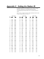
1
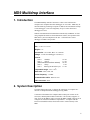
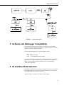
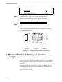
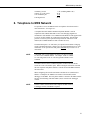
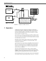
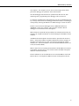
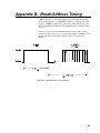
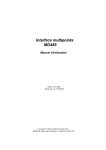
INSTRUCTION MANUAL
MD9 Multidrop Interface
Revision: 5/03
C o p y r i g h t ( c ) 1 9 8 7 - 2 0 0 3
C a m p b e l l S c i e n t i f i c , I n c .
Warranty and Assistance
The MD9 MULTIDROP INTERFACE is warranted by CAMPBELL
SCIENTIFIC, INC. to be free from defects in materials and workmanship under
normal use and service for twelve (12) months from date of shipment unless
specified otherwise. Batteries have no warranty. CAMPBELL SCIENTIFIC,
INC.'s obligation under this warranty is limited to repairing or replacing (at
CAMPBELL SCIENTIFIC, INC.'s option) defective products. The customer
shall assume all costs of removing, reinstalling, and shipping defective products
to CAMPBELL SCIENTIFIC, INC. CAMPBELL SCIENTIFIC, INC. will
return such products by surface carrier prepaid. This warranty shall not apply
to any CAMPBELL SCIENTIFIC, INC. products which have been subjected to
modification, misuse, neglect, accidents of nature, or shipping damage. This
warranty is in lieu of all other warranties, expressed or implied, including
warranties of merchantability or fitness for a particular purpose. CAMPBELL
SCIENTIFIC, INC. is not liable for special, indirect, incidental, or
consequential damages.
Products may not be returned without prior authorization. The following
contact information is for US and International customers residing in countries
served by Campbell Scientific, Inc. directly. Affiliate companies handle repairs
for customers within their territories. Please visit www.campbellsci.com to
determine which Campbell Scientific company serves your country. To obtain
a Returned Materials Authorization (RMA), contact CAMPBELL
SCIENTIFIC, INC., phone (435) 753-2342. After an applications engineer
determines the nature of the problem, an RMA number will be issued. Please
write this number clearly on the outside of the shipping container.
CAMPBELL SCIENTIFIC's shipping address is:
CAMPBELL SCIENTIFIC, INC.
RMA#_____
815 West 1800 North
Logan, Utah 84321-1784
CAMPBELL SCIENTIFIC, INC. does not accept collect calls.
MD9 Multidrop Interface
Table of Contents
PDF viewers note: These page numbers refer to the printed version of this document. Use
the Adobe Acrobat® bookmarks tab for links to specific sections.
1. Introduction.................................................................1
2. System Description ....................................................1
3. Software and Datalogger Compatibility ....................3
4. ID and Baud Rate Selection .......................................3
5. Maximum Number of Dataloggers and
Coax Length...........................................................4
6. Telephone to MD9 Network ........................................5
7. Operation.....................................................................6
A. Cable Specifications and Source References...... A-1
B. Break/Address Timing ........................................... B-1
C. Setting the Station ID ............................................. C-1
D. SC532A ................................................................... D-1
Tables
1-1 Specifications ...........................................................................................1
4-1 ID Settings for MD9 Connected to Computer ..........................................4
Figures
1-1 MD9 Multidrop Interface .........................................................................2
2-1 System Description...................................................................................3
i
MD9 Multidrop Interface Table of Contents
4-1 ID Switch and Baud Rate Selection Jumpers........................................... 4
6-1 Telephone to MD9 Conversion................................................................ 6
B-1 Break/Address Timing Diagram.......................................................... B-1
This is a blank page.
ii
MD9 Multidrop Interface
1. Introduction
The MD9 Multidrop Interface functions as a direct wire link between a
computer and a Campbell Scientific datalogger via coax cable. MD9s may be
networked thereby permitting a computer to address and communicate with up
to 254 dataloggers. Total coax length may be up to 3 miles when fewer
dataloggers are used.
With the communication link initiated and controlled by an IBM PC or clone
using Campbell Scientific's telecommunication software, the operation of the
MD9 in the system is transparent to the user. Call back from a remote
datalogger via MD9 is not possible.
TABLE 1-1. Specifications
Size: 6.5 X 3.5 X 1.25 in.
Weight: 5 oz.
Accessories: SC12 cable, BNC "T" connector
Voltage: 5 Volts from datalogger or SC532(A)
Current:
State 0
"Standby"
State 1
"Active"
(when transmit line drives network)
State 2
"Sleep"
State 3
Pull ring line & buffer bytes
1.2 mA
17 mA
80 mA
3 mA
17 mA
Temperature range: -25 to +50oC
Baud rates: 9600, 1200, 300
Carrier frequency: 1.2 MHz
Communication cable: RG59/U Coax
Cable connector: BNC
2. System Description
The block diagram in Figure 2-1 depicts the connection of a computer to a
network of Campbell Scientific dataloggers using MD9s.
Connection of the MD9 to the computer's RS-232 SIO port is made via the
SC532(A) 9 Pin Peripheral to RS-232 Interface. The SC532(A) supplies +5
VDC power to the MD9 as well as converts the MD9's CMOS voltage levels to
voltage levels consistent with RS-232 requirements. A computer with the
PC201 card installed could use the SC925 Cable to connect directly to the
MD9.
1
MD9 Multidrop Interface
The MD9 at the computer is connected to one or more other MD9s with coax
cable terminated with BNC connectors. Refer to Appendix A for cable
specifications and source references.
The MD9 at the datalogger is connected via an SC12 cable (supplied with the
MD9) and is powered from the datalogger SERIAL I/O port.
Each MD9 includes a BNC "T" connector to allow for coax in/ coax out. "T"
connectors on MD9s at the beginning (computer) and end (last datalogger) of
the network must be terminated with 75 ohm Coax Terminators in order to
prevent signal reflection from one end of the cable to the other. Place
terminators on the ends of the main cable only. Any branch cables from the
main cable to an MD9 should be less than 10 feet in length. No terminator is
used on the T connector at the MD9 on a branch. (Figure 2-1).
NOTE
There are two ground terminals located between the Serial I/O
and Coax Connectors on the MD9. When installing the MD9, a
16AWG or heavier wire should be connected from earth ground
to one of these terminals.
FIGURE 1-1. MD9 Multidrop Interface
2
MD9 Multidrop Interface
FIGURE 2-1. System Description
3. Software and Datalogger Compatibility
PC208 Software Index #5348-00 or higher is required for use with MD9s.
Customers using older software may purchase a software update for a nominal
charge by contacting Campbell Scientific.
The following dataloggers may be used in an MD9 network.
CR10
21X
700X
all
SN6195 or higher
Control Module SN1670 or higher
21Xs and 700Xs with lower SNs require a resistor modification which permits
the respective 5 Volt power supplies to source enough current to operate an
MD9. Contact Campbell Scientific customer service if your datalogger
requires this modification.
4. ID and Baud Rate Selection
Each MD9 in an MD9 network must have a unique ID. The ID is set by the ID
select switch (Figure 4-1). This switch is located under the cover, and can be
accessed by removal of the four cover screws.
Appendix C gives a complete list of ID and switch settings.
3
MD9 Multidrop Interface
TABLE 4-1. ID Settings for MD9 Connected to Computer
Software Used
ID
Dos PC208 (GraphTerm, Telcom, and PC208E)
Windows PC208W (Tcom)
1 - 254
255
NOTE
An MD9 with the ID set to 255 can be used with the DOS PC208
by adding a pound sign (#) to the end of the base MD9 dialing
path in the PC208 station file. This is useful if PC208 and
PC208W must be used on the same MD9 network.
NOTE
Address 255 is also used when the MD9 is connected to a
telephone modem (Section 6).
MD9s are shipped with the Baud Rate Selection Jumpers set at 9600 Baud.
Other baud rates may be selected when necessary. All MD9s in a system must
be set at the SAME baud rate.
9600 Baud
1200 Baud
300 Baud
A-B Short
A-B Open
A-B Short
C-D Short
C-D Short
C-D Open
FIGURE 4-1. ID Switch and Baud Rate Selection Jumpers
5. Maximum Number of Dataloggers and Coax
Length
The maximum coax run that can operate reliably is dependent on the signal loss
due to the type of wire selected and the load placed on the system by each MD9
and coax terminator. The total signal loss in an MD9 system cannot be greater
than 50 db.
Each MD9 attenuates the signal by 0.2 db. Each 100 ft. of Belden 9100 coax
cable attenuates the signal by 0.6 db. The terminator pair account for a 6 db
loss. A quick calculation shows that a network of 34 dataloggers on 5,000 feet
of coax is a workable system.
4
MD9 Multidrop Interface
35 MD9s @ 0.2 db
5,000 ft. @ 0.6 db/ 100 ft.
Coax terminator pair
7 db (including MD9 at PC)
30 db
6 db
Total Signal Loss
43 db
6. Telephone to MD9 Network
It is possible to access an MD9 network via telephone when the network is
miles from the PC. See Figure 6-1.
A Campbell Scientific Model COM200 Telephone Modem is used in
conjunction with a Model PS512M 12 and 5 Volt Charging Regulator to
communicate with an MD9. The COM200 and the MD9 are both supplied with
a 9 pin SC12 cable suitable for connection to the PS512M. The PS512M
provides 5 volts for system operation and performs the function of a null
modem (the COM200 & MD9 are both "modem" devices).
The PS512M requires a 12 Volt battery for operation and contains a charging
circuit to maintain the battery voltage level. The PS512M includes an AC wall
transformer for AC operation A solar panel (optional) may be used if AC is
unavailable.
NOTE
A PS512M with a serial number less than 1712 does not supply
12 volts to the COM200 modem. Use adapter 10704 or connect
12 volts and ground to the 12 volts and ground terminals on the
COM200.
The MD9 connected to the COM200 telephone modem must have the ID
switch set to 255 (all switches open). When creating the station file in PC208
the base telephone with phone number is entered first and the MD9 with ID is
entered second.
When configuring the network in PC208W a modem device (9600 baud) is
added to a COM port, the MD9 device attaches to the Modem, and the
datalogger to the MD9. The base phone number is entered in the MD9 window
and the “Switch Setting of Remote MD9” (ID) is entered in the datalogger
window.
NOTE
In order to make measurements at the telephone to MD9 location,
a datalogger with it's own MD9 is required.
5
MD9 Multidrop Interface
COM200
The null modem on the PS512M has
two 9-pin connectors. The SC12
cable from the COM200 is connected
to either connector and the SC12 from
the MD9 is connected to the other.
FIGURE 6-1. Telephone to MD9 Conversion
7. Operation
Communication between the computer and a datalogger is initiated and
controlled by the computer. The MD9 at the computer is activated when Pin
20, Data Terminal Ready (DTR), is pulled high on the computer's I/O port.
The signal is passed through the SC532(A) and in turn brings Pin 5 Modem
Enable (ME) high on the MD9s I/O port.
When the ME line is pulled high, the MD9 goes from State 0 standby to State 1
active. Once in State 1, any information transmitted by the computer is passed
on to the coax network. This remains true until the DTR and ME line are pulled
low and the MD9 reverts to State 0.
Immediately after the computer enables its MD9 it must send a "BREAK"
command followed by the "ADDRESS" of the destination MD9. See the
timing diagram in Appendix C.
Upon detecting activity on the coax line, remote MD9s convert from State 0 to
State 2. State 2 is a sleep mode in which the MD9 begins a timing routine to
determine if a BREAK has occurred. If a BREAK is not detected, the MD9
returns to State 0. If a BREAK is detected, all remote Multidrop Interfaces
capture and read the ADDRESS.
The properly addressed MD9 progresses to State 3 in which it pulls the
datalogger ring line and buffers any bytes of information which followed the
ADDRESS. All other remote MD9s alternate between States 0 and 2 trying to
identify whether the continuing activity on the network is a new BREAK.
When the datalogger detects the ring line signal it enters its telecommunication
mode and pulls its ME line high causing the MD9 to enter State 1. The link is
6
MD9 Multidrop Interface
now complete. The computer can now send several carriage returns which
permits the datalogger to synchronize at the same baud rate.
Once the datalogger baud rate has been synchronized, data retrieval, data
monitoring and re-programming of the datalogger can be carried out.
To terminate communications with a datalogger, use the E command (followed
by a carriage return) listed in the datalogger instruction manual. The datalogger
will respond by lowering the ME line to its MD9 causing it to return to State 0.
In order to activate the next datalogger station, a BREAK and the next
ADDRESS is sent by the computer. This procedure continues until all
dataloggers in a network have been interrogated.
When all data for a particular time period has been collected and stored by the
computer, the computer's DTR line is released causing the local MD9 to return
to State 0.
An MD9 used in the telephone conversion must be operated in the "Protocol
Mode". In the Protocol Mode, the MD9 communicates with the computer via
the phone and controls activity on the coax network generating the "Break"
command, etc. The Protocol Mode is activated when the MD9 ID switch is set
to 255 (all switches OPEN).
When a station file is set up using PC208 software and the MD9 is not entered
as the FIRST "Interface Device", the software assumes the MD9 at the phone
modem is in the Protocol Mode.
If both conditions are met the MD9 ID set to 255 and the MD9 is not the first
Interface Device the telephone to MD9 conversion is transparent to the user.
7
MD9 Multidrop Interface
This is a blank page.
8
Appendix A. Cable Specifications and
Source References
Belden 1505A:
Conductor: 20 AWG solid copper (.032” ∅)
Jacket Material: PVC
Jacket O.D.: .235
Shield: Braided tinned copper (100% coverage)
Resistance: 10Ω/1000’
Capacitance: 16.2pf/ft.
Impedance: 75 Ohms
Attenuation at 1 MHz: 0.29 db/100’
Belden Wire and Cable
P.O. Box 1980
Richmond, IN 47375
317-983-5200
A-1
This is a blank page.
Appendix B. Break/Address Timing
A BREAK consists of continuous spacing for time greater than 10 times the
inverse of BR (baud rate). The BREAK is followed by a marking period and
single byte ADDRESS. The marking time must be greater than one times the
inverse of BR and the marking time and ADDRESS must be completed within
100 msec.
This is to say that a 9600 baud, the BREAK must be greater than 1.1 m sec
followed by marking for 105 usec. The 8 bit single character ADDRESS (least
significant bit first) is then completed within 100 msec after the end of
BREAK.
FIGURE B-1. Break/Address Timing Diagram
B-1
This is a blank page.
Appendix C. Setting the Station ID
Each MD9, including the one in the MD9 base station, must have a unique
Station ID. Following is a list of all possible Station IDs with the
corresponding setting of the dip switches. Here, 1 represents open and 0 is
closed.
When a station is configured for phone to MD9, PC208 DOS software cannot
recognize an MD9 address greater than 127.
ID
SWITCHES
5678
1234
ID
SWITCHES
1234
5678
1
2
3
4
5
6
7
8
9
10
11
12
13
14
15
16
17
18
19
20
21
22
23
24
25
26
27
28
29
30
32
33
34
35
36
37
38
39
1000
0100
1100
0010
1010
0110
1110
0001
1001
0101
1101
0011
1011
0111
1111
0000
1000
0100
1100
0010
1010
0110
1110
0001
1001
0101
1101
0011
1011
0111
0000
1000
0100
1100
0010
1010
0110
1110
43
44
45
46
47
48
49
50
51
52
53
54
55
56
57
58
59
60
61
62
63
64
65
66
67
68
69
70
71
72
74
75
76
77
78
79
80
81
82
1101
0011
1011
0111
1111
0000
1000
0100
1100
0010
1010
0110
1110
0001
1001
0101
1101
0011
1011
0111
1111
0000
1000
0100
1100
0010
1010
0110
1110
0001
0101
1101
0011
1011
0111
1111
0000
1000
0100
0000
0000
0000
0000
0000
0000
0000
0000
0000
0000
0000
0000
0000
0000
0000
1000
1000
1000
1000
1000
1000
1000
1000
1000
1000
1000
1000
1000
1000
1000
0100
0100
0100
0100
0100
0100
0100
0100
0100
0100
0100
0100
0100
1100
1100
1100
1100
1100
1100
1100
1100
1100
1100
1100
1100
1100
1100
1100
1100
0010
0010
0010
0010
0010
0010
0010
0010
0010
0010
0010
0010
0010
0010
0010
1010
1010
1010
ID
86
87
88
89
90
91
92
93
94
95
96
97
98
99
100
101
102
103
104
105
106
107
108
109
110
111
112
113
114
115
117
118
119
120
121
122
123
124
125
SWITCHES
1234
5678
0110
1110
0001
1001
0101
1101
0011
1011
0111
1111
0000
1000
0100
1100
0010
1010
0110
1110
0001
1001
0101
1101
0011
1011
0111
1111
0000
1000
0100
1100
1010
0110
1110
0001
1001
0101
1101
0011
1011
1010
1010
1010
1010
1010
1010
1010
1010
1010
1010
0110
0110
0110
0110
0110
0110
0110
0110
0110
0110
0110
0110
0110
0110
0110
0110
1110
1110
1110
1110
1110
1110
1110
1110
1110
1110
1110
1110
1110
C-1
Appendix C. Setting the Station ID
ID
40
41
42
129
130
131
132
133
134
135
136
137
138
139
140
141
142
143
144
145
146
147
148
149
150
151
152
153
154
155
156
157
158
159
160
161
162
163
164
165
166
167
168
169
170
171
C-2
SWITCHES
5678
1234
0001
1001
0101
1000
0100
1100
0010
1010
0110
1110
0001
1001
0101
1101
0011
1011
0111
1111
0000
1000
0100
1100
0010
1010
0110
1110
0001
1001
0101
1101
0011
1011
0111
1111
0000
1000
0100
1100
0010
1010
0110
1110
0001
1001
0101
1101
0100
0100
0100
0001
0001
0001
0001
0001
0001
0001
0001
0001
0001
0001
0001
0001
0001
0001
1001
1001
1001
1001
1001
1001
1001
1001
1001
1001
1001
1001
1001
1001
1001
1001
0101
0101
0101
0101
0101
0101
0101
0101
0101
0101
0101
0101
ID
83
84
85
172
173
174
175
176
177
178
179
180
181
182
183
184
185
186
187
188
189
190
191
192
193
194
195
196
197
198
199
200
201
202
203
204
205
206
207
208
209
210
211
212
213
214
SWITCHES
1234
5678
1100
0010
1010
0011
1011
0111
1111
0000
1000
0100
1100
0010
1010
0110
1110
0001
1001
0101
1101
0011
1011
0111
1111
0000
1000
0100
1100
0010
1010
0110
1110
0001
1001
0101
1101
0011
1011
0111
1111
0000
1000
0100
1100
0010
1010
0110
1010
1010
1010
0101
0101
0101
0101
1101
1101
1101
1101
1101
1101
1101
1101
1101
1101
1101
1101
1101
1101
1101
1101
0011
0011
0011
0011
0011
0011
0011
0011
0011
0011
0011
0011
0011
0011
0011
0011
1011
1011
1011
1011
1011
1011
1011
ID
126
127
128
215
216
217
218
219
220
221
222
223
224
225
226
227
228
229
230
231
232
233
234
235
236
237
238
239
240
241
242
243
244
245
246
247
248
249
250
251
252
253
254
255
SWITCHES
1234
5678
0111
1111
0000
1110
0001
1001
0101
1101
0011
1011
0111
1111
0000
1000
0100
1100
0010
1010
0110
1110
0001
1001
0101
1101
0011
1011
0111
1111
0000
1000
0100
1100
0010
1010
0110
1110
0001
1001
0101
1101
0011
1011
0111
1111
1110
1110
0001
1011
1011
1011
1011
1011
1011
1011
1011
1011
0111
0111
0111
0111
0111
0111
0111
0111
0111
0111
0111
0111
0111
0111
0111
0111
1111
1111
1111
1111
1111
1111
1111
1111
1111
1111
1111
1111
1111
1111
1111
1111
Appendix D. SC532A
The SC532A differs from the SC532 in three ways:
1.
2.
3.
Provides 12 V on PERIPHERAL Port pin 8
“PROGRAM” mode
Jack on SC532A POWER input
The SC532A supplies 12 VDC via PERIPHERAL connector pin 8 for the
purpose of powering 12 V peripherals.
The SC532A’s internal jumper selects “SC532” or “PROG” mode. For the
MD9 leave the jumper in the factory default position of “SC532.” “PROG” is
a special mode for satellite transmitters only.
The SC532A has a POWER jack allowing convenient replacement in the event
of AC adapter failure (see CAUTION below). The jack also facilitates
operating the SC532A from datalogger power at remote sites by using optional
field cable (item number 14020) in place of the AC adapter. Simply plug the
cable’s DB9 connector into the datalogger’s CS I/O port for 12 V power. If
you have an earlier datalogger lacking 12 V on CS I/O port pin 8 (DVM test
between paper-clip inserted in pin 8 and GND) the field cable can be modified
to connect to the datalogger’s power terminals as follows:
1.
2.
3.
4.
5.
Unplug field cable from datalogger and SC532A.
Cut off DB9 connector.
Remove cable sheath exposing positive (RED) wire and negative
(BLACK) wire 2 inches back.
Strip ¼ inch of insulation from each wire and tin ends.
Connect RED wire to datalogger “12 V” and BLACK wire to datalogger
power ground terminal. The correct barrel connector polarity is (+) on the
inner bore and (−) on the outer sleeve.
The MD9 requires that a minimum of 6 VDC @ 90 mA be supplied to the
SC532A POWER jack from AC adapter or field cable. The maximum voltage
that can be safely applied to the SC532A POWER jack is 17 VDC.
CAUTION
Before plugging the power connector into the SC532A, if
you have 1) cut off optional field cable’s DB9, 2) replaced
the factory AC adapter, or 3) built your own dc power
cable, make sure that the voltage polarity is correct on the
barrel connector. Application of REVERSED POLARITY
power to the SC532A can damage the SC532A,
datalogger, and peripheral (not covered under warranty)!
Barrel connector inner bore (+)
Barrel connector outer sleeve (−)
The maximum POWER input voltage is 17 VDC!
D-1
This is a blank page.
This is a blank page.
Campbell Scientific Companies
Campbell Scientific, Inc. (CSI)
815 West 1800 North
Logan, Utah 84321
UNITED STATES
www.campbellsci.com
[email protected]
Campbell Scientific Africa Pty. Ltd. (CSAf)
PO Box 2450
Somerset West 7129
SOUTH AFRICA
www.csafrica.co.za
[email protected]
Campbell Scientific Australia Pty. Ltd. (CSA)
PO Box 444
Thuringowa Central
QLD 4812 AUSTRALIA
www.campbellsci.com.au
[email protected]
Campbell Scientific do Brazil Ltda. (CSB)
Rua Luisa Crapsi Orsi, 15 Butantã
CEP: 005543-000 São Paulo SP BRAZIL
www.campbellsci.com.br
[email protected]
Campbell Scientific Canada Corp. (CSC)
11564 - 149th Street NW
Edmonton, Alberta T5M 1W7
CANADA
www.campbellsci.ca
[email protected]
Campbell Scientific Ltd. (CSL)
Campbell Park
80 Hathern Road
Shepshed, Loughborough LE12 9GX
UNITED KINGDOM
www.campbellsci.co.uk
[email protected]
Campbell Scientific Ltd. (France)
Miniparc du Verger - Bat. H
1, rue de Terre Neuve - Les Ulis
91967 COURTABOEUF CEDEX
FRANCE
www.campbellsci.fr
[email protected]
Campbell Scientific Spain, S. L.
Psg. Font 14, local 8
08013 Barcelona
SPAIN
www.campbellsci.es
[email protected]
Please visit www.campbellsci.com to obtain contact information for your local US or International representative.