1
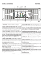
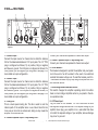
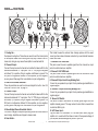
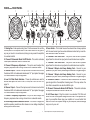
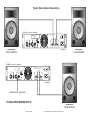
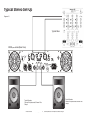
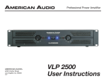
Professional Power Amplifiers
�����
�����
��
�������
����
�����
�����
���
������
�
��
�������
�����
�
�������
�����
��
��
��
����������������������������
��
�������
����
�����
�����
���
������
�
��
�������
�����
�
�������
�����
��
��
��
����������������������������
��
�������
����
�����
�����
���
������
�
AMERICAN AUDIO
®
4295 Charter Street
Los Angeles Ca. 90058
Revised 02/02
��
�
����������������������������
��
User Instructions
This symbol is intended to alert the user to the presence of non insulated "dangerous voltage" within the product's enclosure that may be of sufficient magnitude to
constitute a risk of electric shock to persons.
This symbol is intended to alert the user of the presence of important operating and maintenance (servicing) instructions in the literature accompanying the product.
CAUTION: Risk of the electrical shock - DO NOT OPEN!
CAUTION: To reduce the risk of electrical shock, do not remove cover. No user serviceable parts inside. Refer all servicing to qualified service personnel.
WARNING: To prevent electrical shock or fire hazard, do not expose this amplifier to rain or moisture. Before using this amplifier, read the user manual for further warnings.
Este símbolo tiene el propósito de alertar al usuario de la presencia de “voltaje peligroso“ que no tiene aislamiento dentro de la caja del producto que puede tener
una magnitud suficiente como para constituir riesgo de corrientazo.
Este símbolo tiene el propósito de alertar al usuario de la presencia de instrucciones importantes sobre la operación y mantenimiento en la literatura que vienc con
el producto.
PRECAUCIÓN: Riesgo del choque eléctrico - NO SE ABRA
PRECAUCIÓN: Para disminuir el riesgo de choque eléctrico, no quite la cubierta. No hay piezas adentro que el usario puede reparar. Deje todo mantenimiento al los técnicos cualificados.
ADVERTENCIA: Para prevenir choque eléctrico o riesgo de incendios, no deja expuesto a la lluvia o a la humedad este amplificador. Antes de usar este amplificador, lea
mas advertencias en la guia de operacion.
Ce symbole est utilisé pur indiquer à l’utilisateur la présence à l'intérieur de ce produit de tension non-isolée dangereuse pouvant être d'intensité suffisante pour
constituer un risque de choc électrique.
Ce symbole est utilisé pour indiquer à l’utilisateur qu'il trouvera d'importantes instructions importantes sur l'utilisation et l'entretien de l'appareil dans la littérature
accompagnant le produit.
ATTENTION: Risque de choc électrique - NE PAS OUVRIR!
ATTENTION: Afin de réduire le risque de choc électrique, ne pas enlever le couvercle. Il ne se trouve à l’intérieur aucune piéce pouvant être réparée par l'utilisateur. Confier
l'entretien à un personnel qualifié.
AVERTISSEMENT: Afin de prévenir les risque de décharge ou de feu, n’exposez pas cet appareil à la pluie ou à l’humidité. Avant d’utiliser cet amplificateur, lisez les avertissements supplémentaries situés dans le guide.
Dieses Symobl soll den Anwender vor unisollierten gefährlichen Spannungen innerhalb des Gehäuses warnen, die von Ausreichender Stärke sind, um einen elektrischen Schlag verursachen zu können.
Dieses Symobl soll den Benutzer auf wichtige Instruktionen in der Bedienungsanleitung aufmerksam machen, die Handhabung und Wartung des Produkts betreffen.
VORSICHT: Risiko - Elektrischer Schlag! Nicht öffnen!
VORSICHT: Um ddas Risiko eines elektrischen Schlages zu vermeiden, nicht die Abdeckung enfernen. Es befinden sich keine Teile darin, die vom Anwender repariert
werden könnten. Reparaturen nur von qualifizierte Fachpersonal durchführen lassen.
ACHTUNG: Um einen elektrischen Schlag oder Feuergefahr zu vermeiden, sollte diesen Gerät nicht dem Regen oder Feuchtigkeit ausgesetz werden. Vor Inbetriebnahme
unbedingt die Bedienungsanleitung lesen.
American Audio® - www.americandj.com - V
Vplus Series Amplifiers Power Amplifier User Manual Page 2
CAUTION
Do not open risk of electric shock
CAUTION: TO REDUCE THE RISK OF ELECTRIC
SHOCK, DO NOT REMOVE THE COVER.
THERE ARE NO USER SERVICEABLE PARTS
INSIDE. REFER ALL SERVICE TO YOUR
AUTHORIZED AMERICAN AUDIO® DEALER.
The lightning flash with an arrow triangular
symbol is intended to alert the user to the
presence of non insulated “dangerous voltage” within the products enclosure, and
may be of sufficient magnitude to constitute a risk of electric shock.
The exclamation point triangular symbol is
intended to alert the user to the presence
of important operating and maintenance
(servicing) instructions in the user manual
accompanying the amplifier.
FOR OPTIMUM PERFORMANCE AND
RELIABILITY DO NOT PRESENT THE
AMPLIFIER WITH A SPEAKER LOAD
OF LESS THAN 2 OHMS OR ANY
COMBINATION OF SPEAKERS THAT
TOGETHER ARE LESS THAN 2 OHMS!
POUR ASSURER LA FIABILETE ET
OBTENIT UNE PERFORMANCE OPTIMALE,
NESOUMETTE JAMAIS L’AMPLIFICATEUR
A UNE CHARGE D’IMPEDANCE TOTALE
INFERIEURE A 2 OHMS, NI AVEC UN H.P. NI
EN COMBINAISON DES H.P.
USING ONE SPEAKER, IT MUST BE AVEC UN H.P., IL FAUT UNE CHARGE
D’IMPEDANCE MINIMUM DE 2 OHMS.
RATED AT 4 OR MORE OHMS.
USING TWO SPEAKERS, THEY MUST AVEC DEUX H.P., FAUT POUR CHAOUN UNE
RATED EACH AT 4 OR MORE OHMS.
CHARGE D’IMPEDANCE MINIMUM DE 4
USING THREE SPEAKERS, THEY OHMS.
MUST BE RATED EACH AT 8 OR
AVEC TROIS H.P., FAUT POUR CHAOUN UNE
MORE OHMS.
CHURGE D’IMPEDANCE MINIMUM DE 8
OHMS.
CONTENTS:
Introduction...............................................................................................................................................................................................4
Front Panel....................................................................................................................................................................................................5
Rear Panels
V1000plus................................................................................................................................................................................................6
V2000plus...............................................................................................................................................................................................7
V3000plus..............................................................................................................................................................................................8
Inputs...........................................................................................................................................................................................................9
Outputs............................................................................................................................................................................................................9
Operating Modes........................................................................................................................................................................................13
Protection Circuitry
Limiter................................................................................................................................................................................................13
Short Circuit Protection....................................................................................................................................................................13
Thermal Protection...........................................................................................................................................................................14
Low Cut Filter....................................................................................................................................................................................14
Specifications...............................................................................................................................................................................................15
American Audio® - www.americandj.com - V
Vplus Series Amplifiers Power Amplifier User Manual Page 3
Important Precautions
• To reduce the risk of electrical shock or fire, do not expose this
unit rain or moisture
• Do not spill water or other liquids into or on to your unit
• Do not attempt to operate this unit if the power cord has been
frayed or broken
• Do not attempt to remove or break off the ground prong from the
electrical cord. This prong is used to reduce the risk of electrical
shock and fire in case of an internal short
• Disconnect main power before making any type of connection
• Do not remove the cover under any conditions. There are no user
serviceable parts inside
• Never plug this unit in to a dimmer pack
• Always be sure to mount this unit in an area that will allow proper
ventilation. Allow about 6” (15cm) between this device and a wall
• Do not attempt to operate this unit, if it becomes damaged
• This unit is intended for indoor use only, use of this product outdoors voids all warranties
• During long periods of non-use, disconnect the unit’s main power
• Always mount this unit in a safe and stable manner
• Power cords should be routed so they are not likely to be walked
on, pinched by items placed upon or against them.
• Cleaning -The outside of the unit should be wipe down with a soft
cloth and mild cleaner when needed.
• Heat -The amplifier should be situated away from heat sources
such as radiators, heat registers, stoves, or other appliances
(including amplifiers) that produce heat.
• The fixture should be serviced by qualified service personnel when:
A. The power-supply cord or the plug has been damaged.
B. Objects have fallen, or liquid has been spilled into the unit.
C. The appliance has been exposed to rain or water.
D. The fixture does not appear to operate normally or exhibits a
marked change in performance.
Introduction
Introduction: Congratulations and thank you for purchasing an
American Audio® Vplus
V
series amplifier. This amplifier is a representation of American Audio’s continuing commitment to produce the
best and highest quality audio products at an affordable price. These
amplifiers are designed to provide a big impact in sound reproduction. Please read and understand this manual completely before
attempting to operate your new amplifier. This booklet contains
important information concerning the proper and safe operation of
your new amplifier.
Unpacking: Every V
Vplus series amplifier has been thoroughly tested
and has been shipped in perfect operating condition. Carefully check
the shipping carton for damage that may have occurred during shipping. If the carton appears to be damaged, carefully inspect your unit
for any damage and be sure all accessories necessary to operate
the system have arrived intact. In the event damage has been found
or parts are missing, please contact our toll free customer support
number for further instructions. Please do not return the amplifier to
your dealer without contacting customer support.
Installation: This amplifier is designed to mount into a standard 19”
rack. The front panel provides four holes used to screw the unit into
a rack. The unit also provides a way to rear mount the unit into a
rack for added security. Rear mounting the unit is especially recommended if the unit is to mounted into a mobile rack.
Customer Support: American Audio® provides a toll free customer
support line, to provide set up help and to answer any question
should you encounter problems during your set up or initial operation. You may also visit us on the web at www.americandj.com for
any comments or suggestions. For service related issue please contact American Audio®. Service Hours are Monday through Friday 9:
00 a.m. to 5:00 p.m. Pacific Standard Time.
Voice:
(800) 322-6337
Fax:
(323) 582-2610
E-mail:
[email protected]
American Audio® - www.americandj.com - V
Vplus Series Amplifiers Power Amplifier User Manual Page 4
����
�����
�����
���
������
�
�
��
CONTROLS AND FUNCTIONS
1
2
3
4 5 6
�������
�����
��
����������������������������
FRONT PANEL
7
8
�������
�����
��
��
��
�������
����
�����
�����
���
������
�
9
��
�
10 11
12 13
1. Power Switch - This switch controls the units main power.
�����
2. Channel 1 Limiter Switch (V2000 & V3000 Only) - This is used
�������
�����
��
��
to activate the channels built-in limiter. The limiter reduces the average
output level when the signal begins to distort, this process is designed
to reduce distortion and protect the speakers. See limiter page 12.
��
9
Diagram 1
7. Channel 2 Clip Indicator - This red LED will begin to flash when
�������
channel two begins to overload (clip). At this point channel one will begin to distort. Under heavy clipping activity lower the channel one gain
control to reduce the risk of damage to your speakers and amplifier. This
LED may glow when the unit has been turned off, this is normal.
��
�������
����
�����
�����
���
�
��
����������������������������
������
�
����������������������������
��
3. Channel 1 Clip Indicator - This red LED will begin to flash when
8. Channel 2 Limiter Switch (V2000 & V3000 Only) - This is used
channel one begins to overload (clip). At this point channel one will begin to distort. Under heavy clipping activity lower the channel one gain
control to reduce the risk of damage to your speakers and amplifier. This
LED may glow when the unit has been turned off, this is normal.
to activate the channels built-in limiter. The limiter reduces the average
output level when the signal begins to distort, this process is designed
to reduce distortion and protect the speakers. See limiter page 12.
9. Cooling Vents - These vents are used for proper cooling. Never
4. Channel 1 Protect Indicator - The red Protect LED will begin to
block these vents and keep them clean at all times.
glow when the channel goes into protect mode. When the channel goes
into protect mode all output for that channel will turn off. This is to protect any speakers connected to the channel.
10. Channel 1 Gain Control - This rotary knob is used to control the
output signal of channel one. Turning the knob in a clockwise direction
will increase signal output.
5. Power Indicator - This blue LED will glow when main power is ap-
11. Channel 1 Signal Indicators - These green and yellow LED’s will
plied to the unit. This light may continue to glow briefly after main power
has been turned off, this is normal.
glow according to the average signal output.
6. Channel 2 Protect Indicator - The red Protect LED will begin to
glow according to the average signal output.
glow when the channel goes into protect mode. When the channel goes
into protect mode all output for that channel will turn off. This is to protect any speakers connected to the channel.
12. Channel 2 Signal Indicators - These green and yellow LED’s will
13. Channel 2 Gain Control - This rotary knob is used to control the
output signal of channel two. Turning the knob in a clockwise direction
will increase signal output.
American Audio® - www.americandj.com - V
Vplus Series Amplifiers Power Amplifier User Manual Page 5
V1000
V1000plus
REAR PANEL
1
2
3
PROFESSIONAL POWER AMPLIFIER
INPUT
CH 2
W
WARNING:
TO REDUCE THE
RISK OF FIRE OR ELECTRICAL
SHOCK DO NOT EXPOSE THIS
EQUIPMENT TO RAIN OF MOISTURE
AVIS:
A
VIS: RISQUE DE CHOC ELECT
ELECT-TRIQUE - NE P
PAS OUVRIR.
4
6
CAUTION
4 OHMS MINIMUM IMPEDANCE PRE CHANNEL
4 OHMS MINIMUM IMPEDANCE IN MONO BRIDGE MODE
CH 2
INPUT
CH 1
5
BRIDGE
MONO
6
A
M
P
+
CH 1
120V~60Hz
1000 W
WA
ATTS
ATTS
+
P2 P3 P1
-
+
+
-
STEREO BRIDGE
OUTPUT
Diagram 2
7
8
Connect your channel two speakers to channel two output.
1. Channel 2 Input -
Connect the input source for channel two to either the balance
XLR or the balanced/unbalanced 1/4” input jacks. The 1/4” TRS
plug is configured as follows; Tip is positive, Ring is negative
and Sleeve is ground. The XLR jack is configured as follows; Pin
three positive, pin two negative, pin one ground. See page 9 for
more details on input configuration.
2. Channel 1 Input -
Connect the input source for channel one to either the balance
XLR or the balanced/unbalanced 1/4” input jacks. The 1/4” TRS
plug is configured as follows; Tip is positive, Ring is negative
and Sleeve is ground. The XLR jack is configured as follows; Pin
three positive, pin two negative, pin one ground. See page 9 for
more details on input configuration.
5. Channel 1 Speaker Output - 5 Way Binding Post -
Connect your channel one speakers to channel one output.
6. Circuit Breaker -
This breaker is designed to protect the amplifier and your speakers in the event of an AC overload. In the event of an electrical
overload the breaker will pop-out. To reset the breaker, push it in.
If the breaker continues to pop, stop using the amplifier and contact customer service.
7. Mono-Bridge/Stereo Selectable Switch -
This switch changes the amplifier operating mode from either
stereo or mono bridge. Amplifiers arrive to you preset in the stereo operation mode.
8. A/C Power Input -
3. Cooling Fan -
This is a dual speed cooling fan. This fan is used to cool the
internal parts of the amplifier when in use. Never block the fan
in any way or mount in an enclose rack, doing so may cause the
amplifier to overheat and fail.
4. Channel 2 Speaker Output - 5 Way Binding Post -
Plug this cable in to a standard 110~120v wall outlet. Be sure
that supplied voltage matches that of the required voltage of you
amplifier. Never plug your amplifier in to a wall outlet that does
not match the required voltage of your amplifier, serious damage
may occur to your unit.
American Audio® - www.americandj.com - V
Vplus Series Amplifiers Power Amplifier User Manual Page 6
V2000
V2000plus
REAR PANEL
1
3
2
7
8
4
1
3
2
4
9
1. Cooling Fan Dual speed cooling fans. These fans are used to cool the internal parts
of the amplifier. Never block the fan grills in any way or mount in an enclose rack, doing so may cause the amplifier to overheat and fail.
2. Channel 2 Input Connect the input source for channel two to either the balance XLR or the
balanced/unbalanced 1/4” input jacks. The 1/4” TRS plug is configured
as follows; Tip is positive, Ring is negative and Sleeve is ground. The
XLR jack is configured as follows; Pin three positive, pin two negative,
pin one ground. See page 9 for more details on input configuration.
3. Low Cut Filter Mode Switches These dip switches are used to active and adjust the built-in Low Cut
Filter, see "Low Cut Filter" on page 14.
4. Channel 1 Input Connect the input source for channel one to either the balance XLR or the
balanced/unbalanced 1/4” input jacks. The 1/4” TRS plug is configured
as follows; Tip is positive, Ring is negative and Sleeve is ground. The
XLR jack is configured as follows; Pin three positive, pin two negative,
pin one ground. See page 9 for more details on input configuration.
5. Mono-Bridge/Stereo Selectable Switch This switch changes the amplifier operating mode from either stereo or
mono bridge. Amplifiers are shipped in stereo mode.
6. Fuse Holder -
10
5
11
6
12
1
Diagram 3
This holder houses the external fuse. Always replace with the exact
same type fuse unless otherwise instructed by an authorized American
Audio® technician.
7. Channel 2 XLR THRU Jack This jack is used to send a parallel signal from the channel two input
jacks to another device or amplifier.
8. Channel 1 XLR THRU Jack This jack is used to send a parallel signal from the channel one input
jacks to another device or amplifier.
9. Channel 2 Output Jack/5 way Binding Post Connect to your speaker’s input jack. Red is positive signal and Black is
negative signal.
10. Channel 1 Output Jack/5 way Binding Post Connect to your speaker’s input jack. Red is positive signal and Black is
negative signal.
11. Ground Lift Switch This switch is used to disconnect the internal ground signal from the
amplifier chassis ground. This may reduce the buzz that is caused from
an electrical 60Hz cycle.
12. A/C Power Input Plug this cable in to a standard 110~120v wall outlet. Never plug your
amplifier in to a wall outlet that does not match the required voltage of
your amplifier, serious damage may occur to your unit.
American Audio® - www.americandj.com - V
Vplus Series Amplifiers Power Amplifier User Manual Page 7
V3000
V3000plus
REAR PANEL
1
2
3
5
4
6
1
3
2
4
7
8
9
1
Diagram 4
10
11
12
1. Cooling Fan - Dual speed cooling fans. This fans are used to cool the
internal parts of the amplifier when in use. Never block the fan grills in
any way or mount in an enclose rack, doing so may cause the amplifier
to overheat and fail.
2. Channel 2 Subwoofer Mode On/Off Switch - This switch activates
the amplifier subwoofer mode for channel two.
3. Channel 2 Frequency Adjustment. - This pot is used to adjust the
frequency response when running channel two in subwoofer mode.
4. Channel 2 Input - Connect the input source for channel two to either
the balance XLR or the balanced/unbalanced 1/4” input jacks. See page
9 for more details on input configuration.
5. Low Cut Filter Mode Switches - These dip switches are used to
activate and adjust the built-in Low Cut Filter, see "Low Cut Filter" on
page 14.
6. Channel 1 Input - Connect the input source for channel one to either
the balance XLR or the balanced/unbalanced 1/4” input jacks. See page
9 for more details on input configuration.
7. Channel 1 Frequency Adjustment.- This pot is used to adjust the
frequency response when running channel two in subwoofer mode.
8. Mono-Bridge/Stereo Selectable Switch - This switch changes the
amplifier operating mode from either stereo or mono bridge. Amplifiers
are shipped in stereo mode.
13
14
15
16
9. Fuse Holder - This holder houses the external fuse. Always replace
with the exact same type fuse unless otherwise instructed by an authorized American Audio® technician.
10. Channel 2 XLR THRU Jack - This jack is used to send a parallel
signal from the channel two input jacks to another device or amplifier.
11. Channel 1 XLR THRU Jack - This jack is used to send a parallel
signal from the channel one input jacks to another device or amplifier.
12. Channel 2 Output Jack/5 way Binding Post - Connect to your
speaker’s input jack. Red is positive signal and Black is negative signal.
13. Channel 1 Output Jack/5 way Binding Post - Connect to your
speaker’s input jack. Red is positive signal and Black is negative signal.
14. Ground Lift Switch - This switch is used to disconnect the internal
ground signal from the amplifier chassis ground. This may reduce the
buzz that is caused from an electrical 60Hz cycle.
15. Channel 1 Subwoofer Mode On/Off Switch - This switch activates
the amplifier subwoofer mode for channel one.
16. A/C Power Input - Plug this cable in to a standard 110~120v wall
outlet. Be sure that supplied voltage matches that of the required voltage of you amplifier. Never plug your amplifier in to a wall outlet that
does not match the required voltage of your amplifier, serious damage
may occur to your unit.
American Audio® - www.americandj.com - V
Vplus Series Amplifiers Power Amplifier User Manual Page 8
Set Up
INPUTS - The V
Vplus series amplifiers allows you to use two types of input connectors per a channel, a XLR jack for balanced connections and a 1/4” female jack that will accept balanced and unbalanced connectors. Use these connections to connect the output
signal from a mixer, cross-over or EQ to your V
Vplus series amplifier. A balanced connection is recommended for cable runs longer
that 20ft. When constructing your own XLR cables follow the pin configuration describe below for proper connections. For cable runs
shorter than 20ft. you may choose the 1/4” unbalanced input option. The 1/4” unbalanced input option may be more convenient for
most users due to the abundant supply of prefabricated cables available at your local audio dealer. You may use the two XLR “Input
Thru” jacks to jump a parallel connection to another amplifier or other device. For Example: Connect a XLR cable to the input of channel one. You may now connect a XLR cable from the channel one “Input Thru” jack to the input jack of another amplifier’s channel one
input. This will reduce the use of “Y” cables.
Male XLR Pin Configuration:
US ITT Standard
3
1
2
3 Negative (- data)
Diagram 5
1 Ground/Return/ 0v)
2 Hot (+ data)
Balanced TRS 1/4”
1/4 Plug
Unbalanced TS 1/4” Plug
Diagram 6
Hot (+) Ground/Shield
Negative (-)
Diagram 7
Hot (+)
Negative (-)
OUTPUTS:
Binding Post/Banana Plug - Connect your speakers to the binding post outputs on the rear of the amplifier. The
speaker wire may be connect by bare wire (directly connected, usually for permanent connections), banana plug,
or spade connector. Connections are made to Channels 1 and 2 output’s for stereo mode or across the red terminals of Channels 1 and 2 for Mono Bridge Mode.
Important Notice: Although a speaker will operate with the positive and negative leads plugged into either terminal on the amplifier binding post, be sure to plug the negative lead into the black terminal and positive lead into
Diagram 8
the red terminal. Ensuring proper polarity will avoid speakers being out of phase, that can cause a loss of bass
response.
Important Notice: Banana Plugs - When connecting your speakers to the amplifier using banana jacks; Be sure that the red and black
caps on the binding post are completely screwed in. Insert the banana jacks into the caps of the binding post, be sure that the banana
jack is inserted securely to avoid the risk of it popping out.
American Audio® - www.americandj.com - V
Vplus Series Amplifiers Power Amplifier User Manual Page 9
Bare Wire Connections:
Diagram 10
When connecting your speakers to the amplifier using bare wire; Unscrew the red and black
caps on the binding post, be sure not to completely remove or unscrew the red and black
caps. Strip back the wire insulation 1/2” (13mm). Insert the bare wire into the hole that was
reveled by unscrewing the binding post cap. After inserting the wire into the binding post hole,
screw the binding post cap down on the wire. To reduce the risk of shock or damage to your
amplifier, be sure that the wire connected to one binding post does not come in contact with
that of another.
Typical speaker output using bare wire. Insert
bare wire into the binding post and tighten.
Spade Connector: (Diagram 6)
Diagram 11
When connecting your speakers to the amplifier using spade connector; Unscrew the red and black caps on
the binding post, be sure not to completely remove or unscrew the red and black caps. Insert the spade connector in to the binding post and tighten the caps down on the spade connector. To reduce the risk of shock
or damage to your amplifier, be sure that the wire connected to one binding post does not come in contact
with that of another.
When connecting your speakers to the amplifier using banana jacks; Be sure that the red and black caps on
the binding post are tighten down completely. Insert the banana jacks into the caps of the binding post, be
sure that the banana jack is inserted securely to avoid the risk of it popping out.
Mono Bridge Connections:
Mono bridge operation connections will follow the above descriptions however, when operating in mono
bridge operation the speaker connections will run between the two positive (red) leads. Use channel two positive output terminal for the negative connection and the channel one positive output terminal for the positive
connection.
PROFESSIONAL POWER AMPLIFIER
INPUT
CH 2
Diagram 12
XX
W
WARNING:
TO REDUCE THE
RISK OF FIRE OR ELECTRICAL
SHOCK DO NOT EXPOSE THIS
EQUIPMENT TO RAIN OF MOISTURE
AVIS: RISQUE DE CHOC ELECTA
TRIQUE - NE P
PAS OUVRIR.
CAUTION
4 OHMS MINIMUM IMPEDANCE PRE CHANNEL
4 OHMS MINIMUM IMPEDANCE IN MONO BRIDGE MODE
CH 2
INPUT
CH 1
Typical speaker output using
spade connectors. Insert
bare wire into the binding
post and tighten.
BRIDGE
MONO
6
A
M
P
+
CH 1
120V~60Hz
1000 W
WA
ATTS
ATTS
+
P2 P3 P1
-
+
+
-
STEREO BRIDGE
Uses Channel 1 Inputs Only
OUTPUT
4 Ohm Minimum Speaker Load
American Audio® - www.americandj.com - V
Vplus Series Amplifiers Power Amplifier User Manual Page 10
Rear V1000
V1000plus
Typical Stereo Output Connections
V1000
V1000plus™
shown in illustration
PROFESSIONAL POWER AMPLIFIER
INPUT
CH 2
CAUTION
W
WARNING:
TO REDUCE THE
RISK OF FIRE OR ELECTRICAL
SHOCK DO NOT EXPOSE THIS
EQUIPMENT TO RAIN OF MOISTURE
AVIS: RISQUE DE CHOC ELECTA
TRIQUE - NE P
PAS OUVRIR.
4 OHMS MINIMUM IMPEDANCE PRE CHANNEL
4 OHMS MINIMUM IMPEDANCE IN MONO BRIDGE MODE
CH 2
INPUT
CH 1
BRIDGE
MONO
+
CH 1
6
A
M
P
120V~60Hz
1000 W
WA
ATTS
ATTS
+
P2 P3 P1
-
+
+
-
STEREO BRIDGE
OUTPUT
SPEAKERS
4 OHM MINIMUM
Diagram 13
SPEAKERS
4 OHM MINIMUM
V1000
V1000plus™
shown in illustration
PROFESSIONAL POWER AMPLIFIER
INPUT
CH 2
CAUTION
W
WARNING:
TO REDUCE THE
RISK OF FIRE OR ELECTRICAL
SHOCK DO NOT EXPOSE THIS
EQUIPMENT TO RAIN OF MOISTURE
AVIS: RISQUE DE CHOC ELECTA
TRIQUE - NE P
PAS OUVRIR.
4 OHMS MINIMUM IMPEDANCE PRE CHANNEL
4 OHMS MINIMUM IMPEDANCE IN MONO BRIDGE MODE
CH 2
INPUT
CH 1
BRIDGE
MONO
+
CH 1
6
A
M
P
120V~60Hz
1000 W
WA
ATTS
ATTS
+
P2 P3 P1
-
+
+
-
STEREO BRIDGE
OUTPUT
Diagram 14
Use Channel 1 Inputs Only
TYPICAL MONO BRIDGE SET-UP
SPEAKERS
8 OHM MINIMUM
American Audio® - www.americandj.com - V
Vplus Series Amplifiers Power Amplifier User Manual Page 11
Typical Stereo Set-Up
Diagram 15
Typical Mixer
V3000
V3000plus
series (Rear View)
1
3
2
4
Typical Speaker
Connect to Vplus series Channel One
Output
American Audio® - www.americandj.com - V
Vplus Series Amplifiers Power Amplifier User Manual Page 12
Typical Speaker
Connect to Vplus series Channel Two
Output
OPERATING MODES:
Stereo Operation - Page 10/Figure 9 details an example of a typical stereo set-up. Connect your inputs into channels one and two of
the amplifier. Connect your speakers to the outputs on the rear of the amplifier. Be sure that your front gain controls are turned down
to their lowest level (full counter-clockwise). Turn your amp on. Turn your input source level up. Use your front gain controls to regulate the output volume. Be sure not to raise the volume to the clip level, however an intermittent clip signal is acceptable.
Mono Bridge Operation - Page 9/Figure 8 details a mono bridge set-up. Be sure your amplifier and all other audio equipment is powered down. Flip the Stereo/Mono Bridge switch to the Mono Bridge position. Connect an input signal to channel one. Connect your
speaker across the red output binding post on the rear of your amplifier. Turn your equipment on (your amplifier should always be the
last item you turn on). Apply an input source signal to your amplifier. Turn channel two gain up. Use the channel one gain to regulate
your amplifier output.
Bridged-Mono Mode Caution - The voltage across the output terminals of a bridged V
Vplus series amplifier may equal or exceed 100
volts RMS and may be as high as 130 volts. Use fully insulated CLASS ONE wiring, and the load must be rated for up to 2500 watts
(@4 ohms)
PROTECTION:
LIMITER - The Vplus series comes with a built in limiter. When the input signal overloads, the “CLIP LED’s” indicate a signal overload,
at this time, the master volume should be lowered to reduce distortion. If the input gain level is not reduced the built-in limiter will activate. During signal overload, the limiter will reduce the input audio signal enough to minimize the amount of clipping. A limiter takes
the gain of an overloading signal and reduces it, the reduction in gain reduces distortion that can cause damage to your speakers and
amplifier. During normal operation below clipping, and momentary clips on peaks, the limiter does not affect the audio signal and is
inaudible. It will allow brief clipping of peaks and will only activate when continuous, hard clipping occurs. During excessive clipping
the limiter will reduce the audio signal enough to minimize the amount of clipping. When the input signal decreases enough that clipping ends, the limiter will deactivate and cease its gain reduction. The limiter has a fixed threshold and can not be adjusted.
Safe Power Levels at Different Output Loads:
8-Ohm Loads: The amplifier can operate at practically any power level without risk of overheating. However, if it is pushed hard
enough to continually light the “CLIP ” indicator, the amplifier’s average output power can reach 150 watts.
4-Ohm Loads: If the “CLIP ” indicator flashes occasionally, the amplifier is approaching its maximum long-term power capacity. If it is
lit about half the time, the amplifier channel will probably go into thermal protection within a few minutes.
2-Ohm Loads: Except for an occasional flash, keep the “CLIP ” indicator dark to avoid overheating the amplifier channel. Clipping
should be kept to a reasonable minimum. An amplifier’s peak current draw at full output power into 2 ohms is several times what the
“normal ” draw is, but its various protection circuits will prevent this condition lasting more than a minute or two.
Short Circuit Protection - The V
Vplus series amplifiers all come with built-in Output Short Circuit Protects. The Output Short Circuit
Protection protects the output devices of the amplifier from short circuits and stressful loads. If your speaker lines short, the amplifier automatically detects this problem and discontinues operation for that channel. If one side of your amplifier becomes shorted and
American Audio® - www.americandj.com - V
Vplus Series Amplifiers Power Amplifier User Manual Page 13
goes into protect mode, the other side will continue to operate normally. During short circuit protection,
the "Clip" LED and “Protect" LED will light simultaneously indicating amplifier fault. All channel output
during the “Short Circuit Protection" will be interrupted (i.e. no sound output). Short Circuit Protection
can usually be traced back to the signal output line (i.e. speaker line). Check the line from the output
terminal of the amplifier to the speaker. If this line good, check the internal speaker connections and
components. A short circuit will usually be traced to a bad cable or a bad speaker component and is
rarely traced to the amplifier itself.
Thermal Protection - A single variable-speed fan on the V1000
V1000plus and dual variable speed fans on the V2000
V2000plus and V3000
V3000plus
amplifiers provide adequate cooling. During low level output the fans run at normal speeds. During high output and as heat raises,
(exceeding 90°C.), the fans will run at higher speeds to aid the cooling process. If the heatsink temperature exceeds 91°C., the amplifier will mute until the amplifier cools down. When the amplifier cools below 90°C., the amplifier will return to normal operations. Be
sure not to operate your amplifier below the minimum load ratings to reduce the risk of overheating problems.
Input/Output Protection - The input circuits are isolated by 10k resistors. An ultrasonic network uncouples RF from the output and
helps keep the amplifier stable with reactive loads.
Operating Voltage (AC Mains) - The serial number label indicates the correct AC main voltage. Connecting to the wrong voltage is
dangerous and may damage the amplifier. Always be sure the source voltage for your areas matches the required voltage for your
amplifier.
Gain Controls - The gain controls are located on the front panel and are calibrated in 2dB of attenuation from full gain. It is best to
adjust the amplifier so no “hissing” is heard from speakers with no music being played, this will ensure the lowest possible distortion
during normal operation.
Low Cut Filter (V2000 and V3000 Only) - The low-cut filter removes extremely low frequencies from the audio signal that could cause
speaker distortion or damage. The dip switches on the rear panel allows you to enable or disable the filter for each channel, as well as
adjust either a 50Hz or 30 Hz cut-off. Always use the 50 Hz filter setting if you are using the amplifier to drive a distributed line system
(also known as a constant-voltage line, 70 volt line, etc.). The dip switches on the rear panel allows you to configure the low cut filter.
The diagram below detail the functions of each dip switch, the functions are also printed on the rear panel of the amplifier.
Configuring the Low Cut Filter:
Activating Low Cut Filters - Dip switches 1 and 4 activate and deactivate the Low Cut Filter. Channel 1 filters is
control by dip switch 1 and channel 2 filter is controlled by dip switch 4.
Low Cut Frequency Selector - When the Low Cut Filter is activated, dip switches 2 (channel 1) and 3 (channel
2) will control the frequency roll-off. When dip switches 2 and 3 are in the "ON" the filter will cut off frequencies
at and below 30Hz, when these dip switches are in the "OFF" position the filter will cut off frequencies at and
below 50Hz. Please note: Each channel operates independently of each other allowing each channel to have
different filter settings.
American Audio® - www.americandj.com - V
Vplus Series Amplifiers Power Amplifier User Manual Page 14
OFF
ON
1 2
3 4
CH. 1
CH.2
1 Low Cut
3 ON=30Hz
2
4 Low Cut
On/Off
ON=30Hz
OFF=50Hz
OFF=50Hz
On/Off
V-SERIES AMPLIFIER SPECIFICATIONS
MODEL NO:
Output Power:
2 ohms, 1 khz 1% THD
4 ohms, 1khz, 1%THD
8 ohms, 1khz 1% THD
(Bridge Mode, mono)
4 ohms, 1khz, 1% THD
8 ohms, 1khz, 1% THD
Total Harmonic Distortion:
20Hz-20kHz, @ rated
output power, 8 ohms
Input Sensitivity and
Impedance: @ rated
output power, 8 ohms
Dimensions & Weight:
Weight:
Height
Width
Depth
W
Weight
Frequency Response:
+/- 1db, 1w RMS. 8 ohms
+/- 0.2 db, @ rated output,
8 ohms
V-1000 PLUS
V-1500
315w RMS Per Ch.
N/A
245w RMS Per Ch. 280w RMS Per Ch.
170w RMS Per Ch. 200w RMS Per Ch.
V-2000 PLUS
650w RMS Per Ch.
450w RMS Per Ch.
280w RMS Per Ch.
V-3000 PLUS
V-4000 PLUS
960w RMS Per Ch. 1400w RMS Per Ch.
690w RMS Per Ch. 1010w RMS Per Ch.
440w RMS Per Ch. 600w RMS Per Ch.
600w RMS
510w RMS
N/A
600w RMS
1290w RMS
900w RMS
1930w RMS
1450w RMS
2500w RMS
1650w RMS
Less than 0.1%
Less than 0.1%
Less than 0.1%
Less than 0.1%
Less than 0.02%
1.5v rms
1.5v rms
1.0v RMS (0 dBv)
1.0v RMS (0 dBv)
1.0v RMS (0 dBv)
3.5" (8.8cm)
19" (48.3cm)
15.9" (40.5cm)
26.4 lbs. (12kg)
1.75" (4.4cm)
19" (48.3 cm)
15.25" (40cm)
25 lbs. (10.5kg)
3.5" (8.8cm)
19" (48.3cm)
15.9" (40.5cm)
30 lbs. (13.6kg)
3.5" (8.8cm)
19" (48.3cm)
15.9" (40.5cm)
31 lbs. (14kg)
5.25" (13.3cm)
19" (48.3cm)
15.9" (40.5cm)
61.7 lbs. (28kg)
10 Hz - 40 kHz
10 Hz - 40 kHz
10 Hz - 40 kHz
10 Hz - 40 kHz
10 Hz - 40 kHz
20 Hz - 20 kHz
20 Hz - 20 kHz
20 Hz - 20 kHz
20 Hz - 20 kHz
20 Hz - 20 kHz
Hum & Noise:
Below rated output, 8 ohms 100 dB, unweighted 100 dB, unweighted 100 dB, unweighted 100 dB, unweighted 100 dB, unweighted
Power Consumption: @
rated output power, 8 ohms
Cooling System:
5A @ 120v AC
8A @ 120v AC
7A @ 120v AC
10A @ 120v AC
20A @ 120v AC
1 Dual Speed Fan
and Heatsinks
1 Dual Speed Fan
and Heatsinks
2 Dual Speed Fans
and Heatsinks
2 Dual Speed Fans
and Heatsinks
2 Dual Speed Fans
and Heatsinks
American Audio® - www.americandj.com - V
Vplus Series Amplifiers Power Amplifier User Manual Page 15
©American Audio®
American Audio® is part American DJ® Group of Companies
American DJ® World Headquarters:
4295 Charter Street Los Angeles, CA 90058 USA
Tel: 323-582-2650 / Fax: 323-582-2610
web: www.americandj.com / e-mail: [email protected]