1
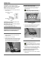
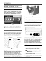
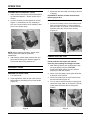
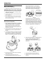
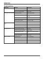
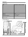
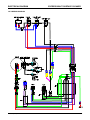
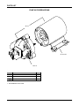
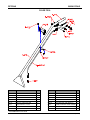
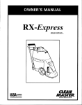
Express Multi Surface
Carpet and Upholstery Cleaner
Model No.:
100-041-017
12 gal Multi Surface Cleaner
Operator and Parts Manual
CLEANMASTER
11015 47TH AVENUE WEST
MUKILTEO WA 98275 U.S.A.
FAX: 1-800-426-4225
Website: http://www.cleanmaster.com
CUSTOMER SERVICE: 1-425-775-7276
MNL50005
Rev. 00 (02-03)
OPERATION
This manual is furnished with each new model. It
provides necessary operation and maintenance
instructions and an illustrated parts list.
MACHINE DATA
Read this manual completely and understand the
machine before operating or servicing it.
Please fill out at time of installation for future reference.
Use the illustrated Parts Lists to order parts. Before
ordering parts or supplies, be sure to have your
machine model number and serial number handy.
Parts and supplies may be ordered by phone or mail
from any authorized parts and service center or
distributor.
Install. Date- ___________________________________
Model No.- ____________________________________
Serial No.- ____________________________________
© CleanMaster
Printed in U.S.A.
CleanMaster is a registered United States trademark
This machine will provide excellent service. However,
the best results will be obtained at minimum costs if:
BEFORE STARTING
The machine is operated with reasonable care.
The machine is maintained regularly – per the
maintenance instructions provided.
INSTALL VENT PLUG IN GEAR CASE VENT
HOLE. FAILURE TO DO SO WILL DAMAGE GEAR
CASE SEAL.
The machine is maintained with manufacturer
supplied or equivalent parts.
TABLE OF CONTENTS
SAFETY PRECAUTIONS ..............................
3
MACHINE COMPONENTS ............................
4
MACHINE SETUP .........................................
4
MACHINE OPERATION ................................
5
DRAINING TANKS .......................................
7
FREEZE PROTECTION ................................
7
MACHINE MAINTENANCE ...........................
8
STORING MACHINE.....................................
10
RECOMMENDED STOCK ITEMS ..................
10
TROUBLE SHOOTING ..................................
11
SPECIFICATIONS ........................................
12
ELECTRICAL DIAGRAM ..............................
13
PARTS LIST .................................................
11
OPTIONS .....................................................
20
WARRANTY POLICY....................................
22
2
Mnl50005 (02-03)
OPERATION
SAFETY PRECAUTIONS
This machine is intended for commercial use. It is
designed to wet clean carpet and upholstery in an
indoor environment and is not constructed for any
other use. Use only recommended cleaning solutions
and accessory tools.
All operators must read, understand and practice the
following safety precautions.
4. Before leaving or servicing machine:
– Turn off machine.
– Unplug cord from wall outlet.
5. When servicing machine:
– Unplug cord from wall outlet.
– Avoid moving parts. Do not wear loose
jackets, shirts, or sleeves.
– Use manufacturer supplied or approved
replacement parts.
The following safety-alert symbols are used throughout
this manual as indicated in their description:
WARNING: Hazardous Voltage. Shock or
electrocution can result. Always unplug machine
before servicing.
WARNING: To warn of hazards or unsafe
practices which could result in severe personal
injury or death.
WARNING: Flammable materials can cause
an explosion or fire. Do not use flammable
materials in tank(s).
FOR SAFETY: To identify actions which must be
followed for safe operation of equipment.
The following information signals potentially dangerous
conditions to the operator or equipment.
FOR SAFETY:
1. Do not operate machine:
– Unless trained and authorized.
– Unless operator manual is read and
understood.
– In flammable or explosive areas.
– With damaged cord or plug.
– If not in proper operating condition.
– Unless cord is properly grounded.
– In outdoor areas.
– In standing water.
– With the use of an extension cord.
2. Before operating machine:
– Make sure all safety devices are in place
and operate properly.
3. When using machine:
– Do not run machine over cord.
– Do not pull machine by plug or cord.
– Do not pull cord around sharp edges or
corners.
– Do not unplug by pulling on cord.
– Do not stretch cord.
– Do not handle plugs with wet hands.
– Keep cord away from heated surfaces.
– Report machine damage or faulty operation
immediately.
– Follow mixing and handling instructions on
chemical containers.
– Connect hoses before turning on pump.
– Be sure chemicals are safe and non-toxic.
Mnl50005 (02-03)
WARNING: Flammable materials or reactive
metals can cause an explosion or fire. Do not use
machine for extraction of these materials.
WARNING: Hot solutions up to 88° C (190°F).
Do not touch with any part of the body. Use
thermometer to gauge temperature.
WARNING: Contents of solution hoses may
be under pressure even after pump is off.
GROUNDING INSTRUCTIONS
Machine must be grounded. If it should
malfunction or breakdown, grounding provides a
path of least resistance for electrical current to
reduce the risk of electrical shock. This machine is
equipped with a cord having an equipmentgrounding connector and grounding plug. The
plug must be plugged into an appropriate outlet
that is properly installed in accordance with all
local codes and ordinances. Do not remove
ground pin; if missing, replace plug before use.
International models will have different cord ends.
GROUNDED OUTLET
(3 HOLE)
GROUNDING
PIN
3
OPERATION
MACHINE COMPONENTS
3
4
1
9
2
6
7
10
8
5
1.
2.
3.
4.
5.
Recovery Tank
Solution Tank
Recovery Tank Lid
Solution Tank Lid
Star Assembly
6.
7.
8.
9.
10.
Power Cord Connector
Solution Tank Coupler to Base
Squeegee connection loop
Recove ry Tank Drain
Solution Hose Connector
MACHINE SETUP
1.
Carefully check carton for signs of damage.
Report damages at once to carrier. The machine
is shipped fully assembled and is ready for use.
WARNING: Flammable materials can cause an
explosion or fire. Do not use flammable materials
in tank(s).
2.
Attach head appropriate for surface to be cleaned
(Figure1). Spindle has a left hand thread. Turn
counterclockwise when installing.
4.
Add a recommended cleaning chemical.
FOR SAFETY: When using machine, follow
mixing and handling instructions on chemical
containers.
5.
To clean, lower head by depressing lever behind
large right wheel (Figure 2). When transporting
machine, raise head again by lifting handle in
front of head.
Fig. 1
3.
Using a clean bucket or hose, fill solution tank
with 45 liters (12 gallons) of hot water, 60° C
(140° F) maximum.
Note: Before installing carpet cleaning head, refer
to page 9 for lubrication instructions.
4
Fig. 2
Mnl50005 (02-03)
OPERATION
ATTENTION: If using powdered cleaning
chemicals, mix prior to adding to solution tank.
NOTE: Prespraying carpet prior to cleaning will
enhance the overall cleaning results.
6.
CLEANING CARPETS WITH WAND
1.
Plug machine’s power cord into grounded wall
outlet. (Figure 3).
Turn on the vacuum switch. Next, activate the
pump by turning on the “Continuous Spray”
switch (Figure 5).
Warning: Do not activate power head
switch when using a wand or accessory tool.
GROUNDED OUTLET
(3 hole)
GROUNDING
PIN
Fig. 3
FOR SAFETY: Do not operate machine unless
cord is properly grounded.
FOR SAFETY: Do not operate machine with the
use of an extension cord.
7.
Fig. 5
2.
Secure recovery tank lid in place.
Take carpet cleaning wand in hand and squeeze
valve trigger while moving the tool in short
forward and backward strokes (Figure 6).
MACHINE OPERATION - WAND
FOR SAFETY: Do not operate machine unless
operator manual is read and understood.
PRE-OPERATION
1.
Vacuum carpet and remove other debris with
standard vacuum.
2.
Inspect power cord for damage.
3.
Attach optional solution hose to quick disconnect
at the back of the machine. Disconnect vacuum
hose from right side of recovery tank and attach
optional vacuum hose in its place (Figure 4).
Fig. 6
WHILE OPERATING WITH A WAND
1.
Overlap each path by 50 mm (2 in).
Warning: Flammable materials or reactive
metals can cause an explosion or fire. Do not
pick up.
2.
Periodically check for excessive foam buildup in
recovery tank. Use a recommended foam control
solution to prevent vacuum motor damage.
ATTENTION: Excessive foam buildup will not
activate the float shut-off screen.
3.
Empty recovery tank every time water is added to
solution tank.
Fig. 4
Mnl50005 (02-03)
5
OPERATION
MACHINE OPERATION - ROTARY
CONTROLS
There are three switches installed in the dash panel
located on the main handle assembly. Place vacuum
switch in the on position. Next, turn on “Power Head”.
For solution output, activate either the “Continuous
Fig 9
Turning the knob clockwise increases the amount of
tilt.
The large tires in the front and the swivel casters in
the rear of the Express allow the machine to easily
pivot and glide in and out of tight places.
CLEANING PATTERN
Fig. 7
Spray” switch or squeeze solution trigger (Figure 7).
The “power head” switch causes the rotary head to
turn.
To achieve maximum results, move the Express with
back-and-forth motions while overlapping preceding
passes by 25 to 50 percent (Figure 10). The more
MANEUV ERABILITY
The ease of handling the Express is a direct result of
the rotary extractor head. Its natural cleaning motion
provides the “drive” for the unit. The slightest push or
pull against the handle causes the rotating head to
produce a pulling force in the forward direction or a
Fig. 10
FORWARD
BACKWARD
soiled the area to be cleaned, the slower the speed of
the cleaning passes. This allows the machine more
time to work. After cleaning an area approximately six
feet square, release the “momentary lever” switch or
turn off the “continuous spray” switch and make
vacuum-only “dry passes” over the area just cleaned.
This will assure maximum water removal and a faster
drying time.
WHILE OPERATING
1.
Fig. 8
pushing force in the backward direction (Figure 8).
The movement of the handle causes the rotary head
to tilt and apply a slight pressure on either the left side
or the right side of the head. If the tilt angle is too
much, the vacuum seal to the carpet will break and
this will adversely affect solution recovery. There is an
adjustment knob under the machine that allows the
operator to increase or decrease this angle (Figure 9).
6
Periodically check for excessive foam buildup in
recovery tank. Use a recommended foam control
solution to prevent vacuum motor damage.
Warning Flammable materials or reactive
metals can cause and explosion or fire.
Do not pick up.
2.
To clean heavily soiled areas, repeat cleaning
path from a different direction.
3.
Empty recovery tank every time water is added to
solution tank.
Mnl50005 (02-03)
OPERATION
CLEANING WITH ACCESSORY TOOLS
1.
Attach solution and vacuum hose as described in
the “Machine Operation – Wand” section of this
manual.
2.
Connect accessory tool and operate as normal
(Figure 11). Remember it is only necessary to
turn on the vacuum switch since activating it also
turns on the solution pump
Fig. 11
NOTE: Before cleaning upholstery, always check
cleaning instructions sewn in furniture by
manufacturer.
3.
After cleaning, relieve water pressure from tool
before disconnecting hose. Squeeze trigger for
five seconds after turning switches off.
DRAINING TANKS
DRAINING RECOVERY TANK
1.
Turn machine off.
2.
Insert supplied 45° elbow in drain valve. Place a
bucket below it and slowly pull up on the handle
(Figure 12).
Fig. 12
Mnl50005 (02-03)
3.
Rinse tank with clean water and empty at the end
of the day.
FOR SAFETY: Remove all water from machine
before trying to lift it.
DRAINING SOLUTION TANK
1.
Connect 3 foot utility hose to quick disconnect at
back of machine and turn on vacuum switch to
pump the water out or attach a vacuum hose and
evacuate water with vacuum motor running
(Figure 13).
Fig. 13
FREEZE PROTECTION
Freeze protection will require the optional
accessory hose package and empty out nozzle.
1.
After draining solution tank as described in step
one of the previous section (DRAINING
SOLUTION TANK), attach vacuum hose as if
preparing to clean with a wand.
2.
Attach 3 foot long utility hose to quick disconnect
at the back of the machine.
3.
Place end of utility hose in end of vacuum hose
and seal with hand (Figure 14).
4.
Turn on vacuum (which also turns on pump) and
continuous spray switch for 30 seconds. This will
fill the pump and hoses with air and prevent
freezing.
Fig. 14
7
OPERATION
gearbox shaft, if not removed, may damage the
gearbox oil seal resulting in loss of oil in the
gearbox. If the gearbox is operated without oil,
severe damage may occur. (This requires
removing the cleaning head. To do this, refer to
“Repair Guide” section of this manual.)
MACHINE MAINTENANCE
To keep machine in good working condition, simply
follow machine’s daily, weekly and monthly
maintenance procedures.
FOR SAFETY: When servicing machine, unplug
cord from wall outlet.
7.
Check the applicator jets in the head to ensure a
proper solution flow. A jet that sprays uneven or
that dribbles needs to be cleaned (Figure 17).
DAILY MAINTENANCE
(Every 4 Hours of Operation)
1.
Empty and rinse out recovery tank thoroughly.
2.
Remove float shut-off screen from recovery tank
and clean (Figure 15.)
FIG. 17
8.
Twist the jet out. Turn it over. Blow out any
obstructions and reinstall the jet. Never use a
sharp solid object to dislodge an obstruction as
this will damage spray jet.
9.
Rinse head assembly and cowling with fresh
water to remove debris.
FIG. 15
3.
When solution tank is empty, remove and clean
solution filter screen located at the end of the
hose inside the solution tank. When replacing, be
certain filter screen lies in the recessed pocket at
bottom of the tank. This will assure that all
solution in used from tank the next time the
machine is used.
4.
Wipe off power cord and check for damage,
replace if necessary. Coil cord neatly after use.
5.
Clean machine with an all purpose cleaner and
damp cloth.
6.
Clean off any accumulated debris on the gearbox
shaft and inside the threaded portion of the hub
(Figure 16). An accumulation of debris around the
FOR SAFETY: Lay machine on its right side when
cleaning. If it lies on the left side oil will grain out
of the gearbox.
10. Coat the motor shaft with lubricant before
reinstalling the cleaning head. Apply grease to
o-ring. Locate the head onto the shaft, making
sure the threads are aligned properly, and rotate
the head counterclockwise (Figure 18).
FIG. 18
FIG. 16
8
Mnl50005 (02-03)
OPERATION
step by step instructions on removing the
cleaning head and seal, refer to the “Repair
Guide” section of this manual.) Always keep a
spare felt seal soaking in 30 weight oil. By
WEEKLY MAINTENANCE
(Every 20 Hours of Operation)
1.
Inspect vacuum hoses for holes and loose cuffs.
FOR SAFETY: When using machine, follow mixing
and handling instructions on chemical containers.
2.
Inspect cord and cord grip for damage. Replace
immediately if damaged.
3.
Lubricate metal shaft on recovery tank drain with
water resistant oil.
4.
Run a vinegar solution of 50% vinegar and 50%
water through the system. Let sit for 15 minutes
then rinse with fresh water.
FIG. 20
immersing the felt in oil, it will expand like a
sponge and provide sufficient seal for a good
vacuum. Place the used seal back in the oil bath
to rejuvenate. Helpful hint: An ideal container in
which to soak the spare felt seal is a commercial
tuna can. It is the right size and shape and does
not require a large amount of oil (Figure 21).
MONTHLY MAINTENANCE
(Every 80 Hours of Operation)
1.
Check the oil level in the gearbox on a monthly
basis. Change the oil yearly. It is very important to
maintain the proper oil level. To check the oil
level, remove the vent plug and look into the
gearbox. Turn the “star” until the inspection hole
in the gear can be seen.
2.
Set the machine so the head is sitting flat. The oil
level should go up to but not past the middle of
the gear.
3.
If oil needs to be added, use quality 80-90 weight
gear oil (Figure 19). Helpful hint: When checking
the oil level in the gearbox, use a toothpick as a
dipstick. The oil level should measure 3/8” deep.
FIG. 21
6.
FIG. 19
4.
Remove and rinse the filter screen from the flow
control solenoid valve.
5.
Change the felt seal (Figure 20). This is
recommended after every ten hours of use. (For
Mnl50005 (02-03)
After placing the refreshed, oil soaked felt seal in
the hub, coat the surface with 30 weight oil.
Lightly oil the inner hub threads before
reattaching the cleaning head to the machine
(Figure 22).
FIG. 22
7.
Lubricate wheels with water resistant oil.
8.
Inspect machine for water leaks and loose
hardware.
9
OPERATION
QUARTERLY MAINTENANCE
(Every 250 hours of Operation)
STORING MACHINE
Check vacuum motor for carbon brush wear. Replace
motor if worn to a length of 10mm (0.38”) or less.
1.
Before storing machine, be certain to drain and
rinse tanks of all water.
2.
Store machine in a dry area in the upright position.
3.
Open recovery tank lid to promote air circulation.
4.
If storing in cold climate, freeze protect.
REPAIR GUIDE
FOR SAFETY: When servicing machine, unplug
cord from wall outlet.
ATTENTION: Do not expose to rain. Store
indoors.
REMOVAL OF CLEANING HEAD
ATTENTION: If storing machine in freezing
temperatures, be sure that machine and solution
system are completely drained and dry.
1.
Unscrew the head in the same direction it turns
during operation. This is clockwise when looking
from the underside).
FOR SAFETY: Be certain machine is on its right
side. Otherwise oil will drain from the vent in the
gearbox.
2.
Once the assembly is loose, spin it off by hand. If
the cleaning head is difficult to remove, use a ¾”
socket wrench on the exposed center nut.
REPLACING THE FELT SEAL
A worn or “dried out” felt will not form a proper
vacuum seal. This will impair the extraction
capabilities of the unit.
1.
Remove cleaning head assembly
2.
Make sure the felt is saturated with oil to insure a
proper seal.
3.
Remove and reverse seal so that the “new” face
is against the hub. Note: Alternating sides will
temporarily extend the life of the felt. However,
the seal may need to be replaced.
4.
Reinstall head assembly. Note: When reinstalling
the head assembly, the felt should compress
against the seal plate during the last quarter
rotation of the head. If this can not be felt, the
seal may need replacement.
10
RECOMMENDED STOCK ITEMS
Refer to Parts List section for recommended stock
items. Stock items are clearly identified with a bullet
preceding the parts description. See example below:
PART #
DESCRIPTION
J-30.
LID, DOME
1
38GRANITE
J39.5GRANITE
TOP,SOL TANK ROTO GRANITE
1
HANDLE,WASTE TANK ROTO GRANI
1
J-39GRANITE
WASTE TANK, ROTO GRANITE
1
• J-
QTY.
Mnl50005 (02-03)
OPERATION
TROUBLE SHOOTING
PROBLEM
CAUSE
SOLUTION
Machine does not operate.
Faulty switches or wiring.
Contact Service Center.
Faulty power cord.
Contact Service Center.
Building circuit breaker tripped.
Reset Breaker.
Solution pump does not operate. Faulty switch or wiring.
Vacuum motor does not
operate.
Poor solution pick-up.
Uneven or no spray.
Mnl50005 (02-03)
Contact Service Center.
Vacuum switch not turned on.
Activate vacuum switch
Pump not primed.
Faulty solution pump motor.
Follow freeze protection procedure if all
else fails.
Contact Service Center.
Faulty pump head.
Contact Service Center.
Trigger on wand not pulled.
Pull Solution Trigger.
Quick couplers not fully engaged.
Connect quick couplers.
Loose or broken wiring.
Contact Service Center.
Faulty vacuum switch.
Contact Service Center.
Defective vacuum motor.
Contact Service Center.
Worn carbon brushes.
Contact Service Center.
Recovery tank drain valve open.
Close valve.
Defective recovery tank lid gasket.
Replace gasket.
Clogged float shut-off screen.
Remove recovery tank lid and clean
screen.
Loose vacuum hose connections.
Secure cuffs to hose.
Defective vacuum hose.
Replace hose.
Plugged spray tips.
Clean or replace tips.
Improper spray tip size or spray angle.
Replace with proper tips.
Worn spray tips.
Replace spray tips.
Solution tank low or empty.
Refill solution tank.
Faulty solution pump.
Contact Service Center.
11
OPERATION
SPECIFICATIONS
Model
EXPRESS MULTI SURFACE CLEANER
LENGTH
1308 mm (51.5 in)
WIDTH
406 mm (16 in)
HEIGHT
1047.7 mm (41.25 in)
WEIGHT
71.6 Kg (158lbs)
SOLUTION TANK CAPACITY
45 L (12 gal)
RECOVERY TANK CAPACITY
45L (12 gal)
SOLUTION PUMP
120 V, 4.13 bar (60psi), .7 A
VACUUM MOTOR – 3 STAGE
@120 V, 10.6A, 1272 W
SEALED WATER LIFT
2718 mm (107 in)
HEAD SPEED
130 RPM
HEAD MOTOR
120V, 1/2HP, 5.6 A, 672W
TOTAL POWER CONSUMPTION
120V, 13.8 A, 1656W
POWER CORDS
1 @ 15.2m (50 ft) 3/12
DECIBEL RATING 3 METERS (10 FT) FROM
MACHINE ON CARPET
<67 db(A)
MACHINE DIMENSIONS
1047.7 mm
(41.25 in)
920.7 mm
(36.25 in)
406.4 mm
(16 in)
12
1308 mm
(51.5 in)
Mnl50005 (02-03)
ELECTRICAL DIAGRAM
EXPRESS MULTI SURFACE CLEANER
120 V WIRING DIAGRAM
Mnl50005 (02-03)
13
PARTS LIST
EXPRESS MULTI SURFACE CLEANER
TANK GROUP
14
Mnl50005 (02-03)
PARTS LIST
EXPRESS MULTI SURFACE CLEANER
TANK GROUP
PART #
DESCRIPTION
PART #
DESCRIPTION
B-09.07
6-32 X 3/8 PHXZINC
4
J-803
LID, VAC EXPRESS
1
B-12.6
6-32 X 1 1/4 PHXZINC
3
K-09.6
CORD 50' 12/3 SJT YELLOW W/LOCK
1
B-14.6
NUT, 6 -32 HEX ZINC NYLOK
3
K-16.96
BUSHING,RELIEF 1/2 NPT
1
B-14.9
NUT, 6 -32 FOR PLASTIC
4
K-16.97
NUT,NYLON BUSHING REL.1/2
2
B-16.2
8-32 X 3/8 PHXSS
4
K-21.4
SWITCH, OMRON MOMENTARY SPDT SWITCH
1
B-17.85
8-32 X 2 PHXZIN C
2
K-21W
SWITCH, SPST WATER RESIS
3
B-18.02
NUT 8 -32 NYLOK, ZINC
2
M-0859
BRACKET,SOLUTION HOSE RETAINER EXP
1
B-49
NUT,BULKHEAD 3/4-16 X.225
2
M-0862
PIVOT PIN,SWITCH LEVER EXPRESS
1
C-03.02
CLAMP, HOSE 1/4" #4
1
M-0866
PLATE, VAC LID RETAINER EXPRESS
1
C-05.05
FILTER, 1/4NPT 50MESH
1
M-18.2
HINDGE, SOLUTION LID EDGE 2 8.125"
1
C-07.7
GASKET,VAC LID EXPRESS
1
N-30.330
PANEL,SW EXPRESS VAC SRAY PWRHD
1
C-13.5
PLUG, HOLE NYLON .562
1
SC-05.024
ELBOW, 45ST VACUUM DUMP
1
C-21.8
SPRING, .25OD X .90 SWITCH EXPRESS
1
SC-05.024A
ELBOW, VAC TANK ASM EXPRESS
1
C-26
FLOAT,VAC SHUT OFF ROTO
1
SE-04/36
HOSE, 1/4 TYGON 36" EXPRESS W/QC
1
C-35.5
HOSE BARB,1 1/2XMPT W/FLA
2
SE-04/8.5
HOSE,1/4 TYGON 8.5" 1/4MPTX1/4MPT
1
C-37
INSERT,TUBE STRAIGHT CONN 3/8"NYLON
1
SE-06.7GRY/15.5
HOSE, 1/4SOL 15.5" 1/4MPT X 1/4MPT
1
C-56
O-RING, 1.75 X .187
3
SE-08.2/9.25
HOSE,9.25"LNG,3/8" LIQUID TIGHT TUB
1
D-01.8OR
BULK HEAD, 1/4" BRASS W/O-RING
1
SJ-3602GRNGNT.01
DRILLED TANK, SOL EXPRESS GRNGRNT
1
D-17
90 ST ELBOW 1/4" NPT
3
SJ-3604GRNGNT.01
DRILLED TANK, VAC EXPRESS GRNGRNT
1
F-11
Q/C 1/4" SOC BR SHUT OFF
2
SJ-3605BLK.01
HANDLE,DRLD BLK 3 SWITCH
1
G-03.19
O-RING,VITON 2-020 BLKHD
1
SJ-43.25A
VAC FILTER ASM, EXPRESS
1
G-15A
VLV,DMP 1 1/2MPT 4BLT BDY
1
SJ-803
LID, COMPLETE VAC W/GASKET EXPRESS
1
J-48CLNMSTR
LID, SOLUTION EDGE 2 GRNGRANITE CM
1
SK-09.86
CORD,PIG TAIL EXPRESS COMP
1
J-801
LEVER, SWITCH EXPRESS
1
SM-0851
COMP UPPER HANDLE ASM,EXPRES PAINTD
1
J-802
PLATE, SWITCH LEVER ATTACH EXPRESS
1
SM-0857
COMP BRKT CORD MOUNT,EXP PAINTD
1
•
QTY.
QTY.
RECOMMENDED STOCK ITEMS
Mnl50005 (02-03)
15
PARTS LIST
EXPRESS MULTI SURFACE CLEANER
BASE GROUP
16
Mnl50005 (02-03)
PARTS LIST
EXPRESS MULTI SURFACE CLEANER
BASE GROUP
•
PART #
DESCRIPTION
PART #
DESCRIPTION
B-11.2
6-32 X 3/4 FHXSS 100 DEG
QTY.
3
C-59
PUSHNUT FASTNER, 1/2 CAP
QTY.
2
B-14.6
NUT, 6 -32 HEX ZINC NYLOK
3
C-97
YOKE END LINKAGE,1/4-28 STEEL
1
B-21
10-32 X 5/16 PHXSS
1
D-04
BUSHING 3/8 X 1/4 NPT BR.
1
B-24
10-32 X 3/4 PHXSS
6
D-07.01
COUP 1/4 NPT X -4 SAE
2
B-24.1
10-32 X 3/4 PHXZINC
3
D-15.2
45 ST ELBOW 1/4 NPT
1
B-26.1
10-32 X 1 1/4 PHXZINC
2
D-17
90 ST ELBOW 1/4" NPT
1
B-26.7
10-32 X 1 1/2 PHXZINC
3
D-20.03
ELBOW 90 3/8NPT X -6 SAE
1
B-28.03
NUT, 10-32 NYLOK ZINK
11
D-41
NIPPLE, 1/4 NPT CLOSE BR
2
B-29.1
WASHER,#10 SS
6
D-43
NIPPLE, 1/4 HEX BRASS
1
B-31.5
1/4-20 X 1/2 HEX CP
2
D-48.5
TEE,STREET 1/4 NPT BRASS
1
B-32
1/4-20 X 3/4 HEX HD C P
6
E-14
CUFF, 1 1/2SLIP X 1 1/4HOSE
1
B-33
1/4-20 X 1 HEX HD CP
18
E-14.69
CUFF,1 1/2"SLIP X 2" WIRE SUPP HOSE
1
B-33.08
1/4-20 X 1 1/2 HEX HD ZINC
2
F-09
Q/C 1/4" PLUG BR SHUT OFF
2
B-33. 45
1/4-20 X 4 HEX HD CP
2
G-37
VALVE,VAC SHUT OFF DUAL
1
B-33. 5
1/4-20 X 4 1/2 HEX CP
1
G-40
VALVE, SOLENOID 120V
1
B-36
NUT 1/4-20 HEX CP
1
J-46.6BLK
MANFLD, BLWR INTAKE EXPRESS
1
B-36.01
NUT 1/4-20 NYLOK ZINK
24
J-47.6BLKMUF
MUFFLER & PUMP MOUNT BLK EXPRESS
1
B-36.3
EYE BOLT, 1/4 -20 X 2" ZINC
1
K-17.4
CLAMP,NYLON CABLE 1/4"
2
B-38.5
WASHER, 1/4 FLAT CP
24
K-17.5
CLAMPS, NYLON CABLE 3/8
1
B-39.5
WASHER, 1/4 INT. STAR
2
L-1600
EXPRESS HEAD ASSEMBLY COMPLETE 110V
1
B-40
SET SCREW 1/4 -28x3/16 SS
2
M-0295
WASHER, 1.125OD X .562ID
3
B-40.01
NUT, 1/4-28 NYLOCK ZINC
1
M-0854.1
PLATE ASM,VAC SNGL VAC EXPRESS
1
B-40.02
NUT, 1/4-28 ZINC
1
M-0856
BUSHING BLOCK,HANDLE EXPRESS
2
B-40.17
5/16-18 X 1 1/4 HEX HD SS
1
M-0858
BAR, CLEVIS ADJUST EXPRESS
1
B-40.85
3/8-16 X 1 HEX HD SS
4
M-0863
HEAD TILT ARM PLATED
1
B-41.5
WASHER, 3/8 FLAT ZINC
4
M-0864
SLIP PLATE -ADJUST WEDGE SUPPORT EXP
1
B-41.7
WASHER, 3/8 LOCK WASHER SS
2
M-0865
ADJUST, GUIDE BAR SCREW EXPRESS
1
B-41.85
NUT, 3/8-16 NYLOK ZINC
2
M-31.175
STANDOFF, 5.7 EDGE 3.190"
3
B-42
WASHER 9/16 x 1 1/4 FLAT
2
M-93
WASHER, .219 X .625 18GA
8
B-42.9
NUT, 7/16-20 JAM NUT ZINC
1
SE-06.7GRY/20B
HOSE, 1/4SOL 20" -4SAE X 1/8MPT
1
C-01.03
BEARING,BALL 2-BOLT FLANGE 3/4"BORE
1
SE-06.7GRY/23
HOSE, 1/4SOL 23" -4SAE X 1/4FPT
1
C-01.37
BUSHING,FLANGED BRONZE.502IDX.875OD
2
SE-06.7GRY/35
HOSE, 1/4SOL 35" -6SAE X 1/4FPT
1
C-02.4
CASTER, 4" SWIVEL
2
SE-10.05/52
HOSE, VAC 1.5" FLEX 52"
1
C-03.2
CLAMP , HOSE 2" #24
1
SE-12.5/3
HOSE,2"FLEX EXH 3" LONG
1
C-03.3
CLAMP, HOSE 2 1/4 #32
3
SE-12.7/36
HOSE, 2" WIRE X 36"LONG
1
C-04.07
COTTER,PIN 1/8 X 1.675" STEEL
1
SJ-13.5
COMP,DRLD & PNTED HEAD LIFT LOCK EX
1
C-05.020
BALL JOINT ASSM 1/4-28
1
SJ-3601BLKCM.01
BASE,DRLD 2XVAC PAR,100PSI BLK ROTO
1
C-05.0215
ELBOW, 90 1.5 X 1.5 SS
1
SL-006
BLOWER, 3STG 120V 5.7COMP #
1
C-06
GASKET, BLOWER/ARLON 1/4"
2
SL-24
PUMP,DIAPH 60PSI 120V W/WIR&SWITCH
1
C-07.35
GASKET, VAC SEAL EXPRESS BASE
1
SM-0850
COMP LIFT BAR ASMBLY,EXPRESS PAINTD
1
C-11.63
KNOB, HEIGTH ADJUSTMENT EXPRESS
1
SM-0852
COMP LOWER HANDLE ASM,EXPRES PAINTD
1
C-21.7
SPRING,.68OD X 1.25H EXPRESS
1
SM-0853
CMP BRKT LWR HNDL MNT,EXPRES PAINTD
1
C-21.9
SPRING, .375OD X 3" TEE BAR EXPRESS
1
SM-0855
COMP AXLE ASM,EXPRESS PAINTD
1
C-23.8
WHEEL 10" - 1/2"BORE
2
SM-0860
COMP ADJUST BAR ASM,EXPRES PAINTD
1
C-37
INSERT,TUBE STRAIGHT CONN 3/8"NYLON
1
SM-0861
COMP ADJST GUIDE BAR ASM,EXP PAINTD
1
C-51.5
MUFFLER, FOAM EXPRESS
1
SR-04/.30
FOAM, MUFFLER 5.5 X 3.25
1
RECOMMENDED STOCK ITEMS
Mnl50005 (02-03)
17
PARTS LIST
EXPRESS MULTI SURFACE CLEANER
ROTARY HEAD ASSMEBLY
`
18
PART NO
DESCRIPTION
000-006-009
BASE, HIGH SPEED
QTY.
1
000-052-080
NIPPLE, 1/8" X 4" BRASS
5
000-052-089
ELBOW, 1/8"BRASS FEMALE
5
000-052-276
ROTARY UNION, 1/8" NPT
1
000-052-427
BUSHING, 1/8” MPT X 1/8” FPT
5
000-057-047
GASKET, FELT HUB
1
000-059-001
GEARBOX, COMPLEATE - SPUR
1
000-064-012
HEAD, RX SKID ASSEMBLY
5
000-068-174
HOSE, 1" ID GRAY - VACUUM
5
000-076-057
JET, 110015 QUICK CONNECT (JET, O-RING, BODY)
5
000-094-009
NUT, 1/4-20 S/S NYLOK
5
000-105-008
PLATE, CAST BASE - SEAL
2
000-106-014
PLUG, GEARBOX VENT
1
000-107-0201
HUB,DOUBLE THREAD RX VACUUM
1
000-107-089
STAR, STAINLESS STEEL HEAT TREATED
1
000-143-012
SCREW, 5/16-18 X 3/4" S/S HEX HD CAP SCREW
5
000-143-162
SCREW, 5/16" X 1", 1/4-20 S/S STRIPPER
5
604-052-013
RX EXPRESS III ELECTRIC MOTOR ASSEMBLY
1
604-053-003
EXPRESS VACUUM HEAD ASSEMBLY
1
Mnl50005 (02-03)
PARTS LIST
PUMP 60 PSI BREAKDOWN
SL-24
SL-24.136
L-24.13
`
PART #
DESCRIPTION
QTY.
• SL-24
PUMP,DIA 60 PSI 120V W/WIR & SW
1
• L-24.13
PUMP,DIA HEAD ASM W/SWT 60PSI
1
MOTOR, 60PSI 120V W/PLUGS
1
• SL24.136
• RECOMMENDED STOCK ITEMS
Mnl50005 (02-03)
19
OPTIONS
20258 ECONO
FLOOR TOOL
PART #
DESCRIPTION
QTY.
PART #
B-24.1
10-32 X 3/4 PHXZINC
1
•
B-26.57
10-32 X 1 3/8 PHX ZINC
1
B-28.03
NUT, 10-32 NYLOK ZINK
2
B-40.15
5/16-18 X 3/4 HEX CP
2
B-40.33
NUT 5/16-18 NYLOCK, ZINC
C-07.9
GRIP, FLRTOOL 1 1/2 X 6
D-15.2
D-41
F-09
DESCRIPTION
QTY.
Q/C 1/4" PLUG BR SHUT OFF
1
G-23
VALVE, KNGSTN STD S BND
1
•
JET, 11006 E VEE BRASS
1
M-16.5
HOE HANDLE,ECONO FLRTL
1
2
M-16.5A
"U"CLAMP,SUPP HOE HNDL EC
1
1
M-19.5
WAND,FLOORTOOL COMP. ECONO
1
45 ST ELBOW 1/4 NPT
1
SC-82
TRIGGER,COMP KNGSTN VALVE
1
NIPPLE, 1/4 NPT CLOSE BR
1
SE-06.7/47
HOSE,1/4 SOL 47"FLRTL ECO
1
H-37
• RECOMMENDED STOCK ITEMS
20
Mnl50005 (02-03)
OPTIONS
20078A
HAND TOOL
PART #
Description
PART #
Description
B-05.5
4-40 X 7/8 PHXZINC
1
GR-2-006N70
O-RING,2 -006 BUNA 70DR
2
B-07.5
NUT, 4 -40 HEX ZINC NYLOK
1
GR-2-011N70
O-RING,2 -011 BUNA 70DR
1
B-11.5
6-32 X 1 PHXZINC
2
GR-2-013N70
O-RING,2 -013 BUNA 70DR
1
B-14.6
NUT, 6 -32 HEX ZINC NYLOK
2
H-03.5
CAP NUT,TEE JET POLYPRO
1
B-16.2
8-32 X 3/8 PHXSS
1
H-18.8
JET, 110015 STD FLAT SPRYTIP PLSTIC
1
B-18.01
NUT 8 -32 NYLOK, SS
1
J-62
VALVE, 4" DETAIL TOOL AS MOLDED
1
C-05.07
FILTER, 4" DETAIL TOOL 50 MESH
1
J-63
TRIGGER, 4" DETAIL TOOL
1
C-08.5
GROMMET, CLEAR DETAIL TOOL
1
J-64
ELBOW, 4" DETAIL TOOL
1
D-02
BUSHING 1/4 X 1/8 NPT BR
1
M10.5A
COUPLER, 1.5" VAC HOSE ALUM
1
E-13.5
CUFF,EXTRN HOSE 1 1/2SLPX1 1/4HOSE
1
SE-02/16.5A
HOSE, 1/8 BLK 16.5" ASM W/EXTRN CUFF
1
E-14
CUFF, 1 1/2SLIP X 1 1/4HOSE
1
SE-10/12
HOSE, VAC 1 1/4 GREY/BLACK 12" LONG
1
F-09
Q/C 1/4" PLUG BR SHUT OFF
1
SG-04.5
STEM ASM 4"TOOL BUNA W/BRASS CAP
1
G-04.5
GUIDE, VALVE STEM HEX BRASS
1
SJ-60
HANDLE ASM, 4" DETAIL TOOL
1
G-05.5
STEM, VALVE SS 4" DETAIL TOOL
1
SJ-62
VALVE,NYLON COMPLETE STD 4"DETAIL
1
G-08.5
SPRING, VALVE 4" UPH TOOL
1
Mnl50005 (02-03)
QTY.
QTY.
21
WARRANTY POLICY
PARTS ONLY – STANDARD REPLACEMENT POLICY
For the first 12 months from the date of purchase, CleanMaster will warranty all components against material and
workmanship defects. In the event of a part failure, please call your distributor to obtain a replacement part.
If you are unable to contact your distributor, you may contact CleanMaster parts direct at (425) 775-7276. You will
be asked to provide the machine serial number, date of purchase and a detailed description of the failure including
the part number. An RMA number for the return of the failed part will be issued at the time the order is taken. This
number should be marked on the outside of the package containing the returned part.
CleanMasters policy is to ship warranty parts either COD or on open account with previously established credit. Your
account will be billed for the part and freight until the failed part has been returned and inspected. The customer is
responsible for additional charges for expedited freight. It is also the responsibility of the customer to pay the return
freight on the failed part. If warranty is granted, credit or a refund will be issued for the purchase price of the part and
for the cost of ground freight. If warranty is denied, you will be contacted. A credit will not be issued for either freight
or the part. The failed part will be returned to you at your request.
CleanMaster will pay labor for warranty repairs on new machines for 90 days from the date of purchase and must be
pre-approved. CleanMaster will pay Authorized Distributors at the current warranty labor rate.
HOW TO OBTAIN A RETURN AUTHORIZATION
Prior to shipping any part, assembly or machine to CleanMaster a Return Authorization Number must be requested
from CleanMaster and displayed prominently on the outside of all packages containing parts or machines for
warranty consideration to be processed and in effect. A Return Authorization can be obtained by calling
CleanMaster Service Department at 1-425-775-7276. The machine and/or part serial number must be
communicated to CleanMaster Customer Service to receive a Return Authorization Number. Any machine, part or
assembly must be returned with its original serial number as affixed by CleanMaster for warranty consideration to be
th
in effect. All returns will be sent to CleanMaster at 11015 47 Avenue West, Mukilteo Wa. 98275. Fax
communications can be sent to 1-800-426 -4225 and emails sent to [email protected].
22
Mnl50005 (02-03)
WARRANTY
CleanMaster warrants the Express Cleaning Machine against defects in material and workmanship under
normal use and service. CleanMaster, hereby, extends a limited three-year warranty on the polyethylene machine
housing of the Express against cracking or leaking and a one-year warranty on the rest of the machine against
manufacturing defect or workmanship subject to the terms and conditions that follow.
TERMS AND CONDITIONS
The warranty obligation extends only to the repair or replacement of parts, assemblies or machine housing found
upon examination by CleanMaster to be defective in manufacturing or workmanship, and CleanMaster reserves
the right to make that determination. Any adjustment or replacement of defective parts made under this warranty
does not void the warranty; neither does it extend the original warranty beyond its term.
Repair or replacements of any machine component(s) with any part(s) other than genuine CleanMaster parts will
immediately void this and all warranties.
Filters, brass fittings, seals, o-rings and quick disconnects are considered expendable in normal use and are not
covered by this warranty.
Dry cleaning solvents cannot be used in the Express.
This warranty shall not cover any Express machine housing, part or assembly if there is evidence of misuse,
alteration, owner neglect, lack of proper maintenance, improper chemical use, improper voltage, abuse, accident,
freezing, flood, fire, etc. and any and all circumstances beyond CleanMaster’s control.
In no event shall CleanMaster be liable for loss of use, incidental or consequential damages or any damages to
persons or property.
th
11015 47 AVENUE WEST, MUKILTEO WA 98275 USA
Phone 800-426-8972, 425-775-7272; Fax 800-426-4225;
Website: http://www.cleanmaster.com
PLEASE RETURN REGISTRATION WITHIN 10 DAYS OF RECEIVING YOUR EXPRESS CLEANING MACHINE.
KEEP THIS COPY FOR YOUR RECORDS
Date Received
WARRANTY
REGISTRATION
Registered Owner(s)
Address
Phone Number
Fax Number
Email Address
Machine Serial Number
Purchased From (Distributor)
Mnl50005 (02-03)
23
24
Mnl50005 (02-03)
WARRANTY
CleanMaster warrants the Express Cleaning Machine against defects in material and workmanship under
normal use and service. CleanMaster, hereby, extends a limited three-year warranty on the polyethylene machine
housing of the Express against cracking or leaking and a one-year warranty on the rest of the machine against
manufacturing defect or workmanship subject to the terms and conditions that follow.
TERMS AND CONDITIONS
The warranty obligation extends only to the repair or replacement of parts, assemblies or machine housing found
upon examination by CleanMaster to be defective in manufacturing or workmanship, and CleanMaster reserves
the right to make that determination. Any adjustment or replacement of defective parts made under this warranty
does not void the warranty; neither does it extend the original warranty beyond its term.
Repair or replacements of any machine component(s) with any part(s) other than genuine CleanMaster parts will
immediately void this and all warranties.
Filters, brass fittings, seals, o-rings and quick disconnects are considered expendable in normal use and are not
covered by this warranty.
Dry cleaning solvents cannot be used in the Express.
This warranty shall not cover any Express machine housing, part or assembly if there is evidence of misuse,
alteration, owner neglect, lack of proper maintenance, improper chemical use, improper voltage, abuse, accident,
freezing, flood, fire, etc. and any and all circumstances beyond CleanMaster’s control.
In no event shall Cleanmaster be liable for loss of use, incidental or consequential damages or any damages to
persons or property.
th
11015 47 AVENUE WEST, MUKILTEO WA 98275 USA
Phone 800-426-8972, 425-775-7272; Fax 800-426-4225;
Website: http://www.cleanmaster.com
PLEASE RETURN REGISTRATION WITHIN 10 DAYS OF RECEIVING YOUR EXPRESS CLEANING MACHINE.
RETURN THIS COPY
Date Received
WARRANTY
REGISTRATION
Registered Owner(s)
Address
Phone Number
Fax Number
Email Address
Machine Serial Number
Purchased From (Distributor)
Mnl50005 (02-03)
25
26
Mnl50005 (02-03)