1
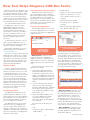
November & December 2014 Putting It All Together New Seminar Reveals Solutions to Top Service Concerns What can cause an air conditioning compressor to suffer an early death, one of the most common service concerns for service centers? An insufficient oil charge? Moisture in the system? Contaminated refrigerant oil? Wrong oil type? All of the above? The compressor is the heart of the A/C system, pumping refrigerant and refrigerant oil through the system. A low oil level or the wrong oil type or viscosity will accelerate compressor wear. Moisture can lead to internal c orrosion. Contaminated refrigerant oil can clog the orifices, screens and control valves and deteriorate the rubber hoses. So the answer is all of the above. But the answer also is system flushing, which will remove the old oil and most contaminants from the A/C system and components, and checking the appropriate Service Information to determine the correct amount and type of oil before installing a new compressor. The new ACDelco seminar, Today’s Top Service Concerns (S-DS11-17.01SEM), covers some of the top service concerns affecting many aftermarket shops, such as A/C compressor service. The seminar offers technical solutions as well as tips to ensure a proper repair. Information presented in the seminar reviews the service issue, some of the typical causes, and how to properly address the concern. Case studies provide a descriptive investigation of each issue along with the details needed to determine the fundamental reasons for a cause and correction. Here’s a quick look at a few of the topics covered in the three-hour seminar. Power Steering Power steering system failure may be caused by improper pulley removal and installation, re-using old O-rings, improper fluids, and other factors. The seminar presents detailed information on power steering fluid and flushing procedures. IN THIS ISSUE Putting It All Together in Top Service Concerns Seminar. . . . . . . . . . . . . . . . . . . . . . 1 New CONNECTION to Parts Ordering . . . . . 2 New Tool Helps Diagnose CAN Bus Faults. 4 New Glow Plug Bore Reamer Available. . . . 5 Bosch Diagnostic Equipment Rebate. . . . . . 6 GM Dealer Equipment Diagnostic Tools Promotion . . . . . . . . . . . . . . . . . . . . . . . . 6 ACDelco Sponsors HVAC Technology Seminar at 2015 MACS Event. . . . . . . . . . . . . 6 Tech Tips . . . . . . . . . . . . . . . . . . . . . . . . . . . . . . 7 Training Update. . . . . . . . . . . . . . . . . . . . . . . . . 8 www.acdelcotechconnect.com, click the Newsletters link HVAC A/C compressor failure and compressor replacement are reviewed. Before installing a new compressor, determine how much oil is required in the system. Ensure the correct oil types and amounts are used. continued on page 3 Follow ACDelco Scan the code to download a PDF ACDelco Provides a New CONNECTION to Parts Ordering ACDelco is renaming WIP to CONNECTION! With the new CONNECTION, service centers have a business-to-business online parts ordering tool that directly links them to their parts supplier. The new name of CONNECTION better reflects the tool’s purpose of being a direct source for quickly and accurately finding and ordering nearly 90,000 ACDelco automotive parts across 37 product lines that fit Chevrolet, Buick, GMC, Cadillac, Ford, Chrysler, Toyota, Nissan, Honda and most vehicles on the road today. CONNECTION also enables purchases of other products from your The new CONNECTION. ACDelco supplier. Users can log in to CONNECTION at www.acdelcoconnect.com. It’s geared s pecifically for the professional trade and includes daily news for service center technicians, counterpersons, business managers, and owners in the following categories: Automotive Service and Repairs, Business Tips, Industry Trends, Automotive Technical Education, and the Latest Vehicle Technology. The ACDelco Community also is available at www. acdelcoconnect.com. Use a VIN to search for parts on a mobile device. First time users need to register for the site by accessing the Community through CONNECTION. Once registered, members can use a home computer or mobile device to find information on repairs and best practices, communicate with other service center professionals around the country, and find CONNECTION news, such as tips on using the new features, release information, and how-to videos. Access from Anywhere A valuable feature of CONNECTION is the mobile device site with VIN scanning. The mobile site allows parts look-up and ordering in three simple sections for maximum efficiency: • Stock Check: Select a branch to display parts pricing and quantity information, or add directly to the shopping cart. • Catalog: Find parts by uploading a VIN from a photo (first-time users are prompted to download a VIN scan app), select Year/Make/Model/Engine information or Previous Vehicle. Displays part name, part number and price all in the browser window so scrolling is eliminated, or select the “See All” option. Parts can be added directly to the shopping cart. • Place Order: Click the Order tab in the tab toolbar; enter the order details, including delivery options and purchase order number; and then click Place Order. continued on page 3 2 Volume 21, Number 6 (ST-PU-0006-14) ACDelco TechConnect is published bi-monthly and online for technicians of Professional Service Center and Key Fleet accounts to provide timely service information, increase knowledge and improve the performance of the service center. ACDelco 360 represents our mission to look at our businesses at every possible angle to provide value and assistance to our distributors and their customers as well as offer a full circle of support with programs, tools, training and marketing focused on enhancing and growing our partnership successfully. Publisher: Rick Balabon, ACDelco E-mail / richard.balabon@gm Senior Editor: Greg St. Aubin, ACDelco E-mail / [email protected] Editor: Peter Robert, ACDelco E-mail / [email protected] Technical Editor: Mark Spencer E-mail / [email protected] Production Manager: Marie Meredith Desktop Publishing: 5by5 Design LLC E-mail / [email protected] Write to: * ACDelco TechConnect P.O. Box 500 Troy, MI 48007-0500 On the Web:: To read or print recent issues of TechConnect: –www.acdelcotechconnect.com, click the Newsletters link. ACDelco service tips are intended for use by p rofessional technicians, not a “do-it-yourselfer.” They are written to inform those technicians of c onditions that may occur on some vehicles, or to provide information that could assist in the proper service of a vehicle. Properly trained technicians have the equipment, tools, safety instructions and know-how to do a job properly and safely. If a condition is described, it cannot be assumed that the information applies to all vehicles or that all vehicles will have that condition. All materials and programs described in this m agazine are subject to change. Submission of materials implies the right to edit and publish. Inclusion in the publication is not necessarily an endorsement of the individual or the company. TechConnect is published for ACDelco by Sandy Group, Troy, MI. ©2014 ACDelco. All rights reserved. New Seminar Reveals Solutions Batteries A drained battery that is capable of holding a charge may be caused by a parasitic drain. A parasitic draw test, along with a circuit/system test, is covered in the seminar. Brakes The keys to a successful brake s ervice involve making the right call on rotor refinishing, cleaning all components and proper assembly. Burnishing the brake pads and rotors should be performed whenever the brake rotors have been refinished or replaced, or the brake pads have been replaced. Rotating Electrical Causes of charging or starting system failure can include high resistance in the battery cables or an oil leak that enters an electric motor. Before replacing components, replace damaged cables or terminals and repair any oil leaks. In addition, tips on starter motor installation, drive belt diagnosis, and automatic tensioner diagnosis are covered. Water Pumps Water pumps may fail due to contamination and corrosion. Failure to flush the cooling system and replace the coolant can lead to repeat failure. When installing a new water pump, clean all sealing surfaces, do not strike the water pump shaft (this will cause damage to the new water pump), and turn the hub by hand to check for rotation. Oil Filters If the oil regulating valve and the bypass valve on the engine become “sticky” from dirt and contaminants, too much pressure may enter into the filter and cause the element to collapse or bulge out. If a damaged filter element is discovered, perform a complete inspection of the filter bypass valve and the pressure regulator valve. Suspension Installing air shocks/struts requires cycling the shock/strut to spread lubricant inside the diaphragm to avoid binding. Inflate the air diaphragm through the air fitting until the shock/strut fully extends. Leave the shock/strut fully extended to make it easier to install. Fuel Pumps A poor connection between the body harness electrical connector and the fuel pump can result in drivability c oncerns. Installation of the fuel pump connector is quick and easy with the proper tools. Check each splice for electrical continuity using a digital ohmmeter — a reading very close to zero ohms indicates the crimps are good. New CONNECTION The full CONNECTION site also can be accessed from the menu, providing users with complete access to all of the functionality and features of the parts ordering tool. The mobile site is available on ultiple handheld devices, making m it possible for technicians to order parts without leaving the service bay. Information entered on the mobile site also is available on the user’s desktop computer. To get started, log in at www.acdelcoconnect.com on your mobile device. More Support To become more familiar with the various elements of the parts ordering tool, check out the Training link under Tools as well as Help on the top navigation bar. There are several short videos that describe how to use the different – continued from page 1 Emissions When removing spark plugs from aluminum heads, allow the engine to cool. The heat of the engine in combination with a spark plug that is still hot may cause the spark plug threads to be damaged or strip the cylinder head upon removal. An improperly torqued spark plug can cause a compression loss-misfire. Body Electrical Fretting corrosion is a buildup of insulating, oxidized wear debris that can form when there is a small motion between electrical contacts. When diagnosing intermittent electrical c onditions, check for poor connection/terminal retention, micro motion, or a connector, component or wiring harness that is not properly secured, resulting in movement. ACDelco Training To enroll in the Today’s Top Service Concerns seminar or other ACDelco training classes, go to www.acdelcotechconnect.com and click the Training tab. To learn when ACDelco seminars will be scheduled in your area, contact your local ACDelco distributor. –Thanks to Peter Robert – continued from page 2 features in CONNECTION, such as “How to Link Accounts for ePromotions” and “How to Smart Search.” Quick Reference Guides also provide a high-level overview of featured products. Product videos and technical support will soon be available on CONNECTION as well. Use the Feedback button to request any additional topics you would like to see. CONNECTION will continue to feature the ACDelco Specialty Catalogs: Illustrated, Battery, Pigtail, MDHD Filter, and Chemical. Plus, enhancements have been made to the Illustrated Catalog with the addition of Regular Production Option (RPO) codes and Tiered Branding — ACDelco Professional, Advantage, and Specialty — parts listings. 3 Finally, the number of shop management systems that can be integrated with CONNECTION has increased, making it one of the quickest and easiest ways to look up and order parts. CONNECTION ePromotions • Enroll in TIS2Web (Technical Information System) for 2015 and earn back up to $1,000 of your TIS2Web subscription fee (Option 2) by purchasing ACDelco products through CONNECTION. • Get access to GM Service Information at no additional charge for the following month once you reach a target of $3,000 in ACDelco purchases via CONNECTION in any given month. –Thanks to Kelli Abbott and Kim LaClear New Tool Helps Diagnose CAN Bus Faults GM has released new diagnostic software to help technicians identify a starting point in diagnosing faults in a CAN bus (GM also calls this a LAN) by looking at how connectors and wiring are working or not working. With this information, diagnostic time can be reduced for intermittent electrical conditions. The new Data Bus Diagnostic Tool is an application that uses existing GM Multiple Diagnostic Interface (MDI) or Bosch Mastertech Vehicle Communication Interface (VCI) tool functionality. You will use your MDI or VCI tool, a computer with access to the web-based Techline Information System (TIS2Web), and an active TIS license. Determine Physical Layer Status • Double opens CAN buses have characteristic voltages under different fault conditions. By monitoring bus voltage, it’s possible to identify whether or not the bus is physically OK. It’s also possible to identify the type of fault that’s present (CAN LO/HI open, short, ground offsets, etc) by monitoring bus voltage. • Single wire shorts to power/ground Three-In-One Application • Power faults (open supply, blown fuse, broken enable line, etc) The Data Bus Diagnostic Tool is actually three sub-applications in one. Each one has its own tab on the application's graphic interface. To download the software, click the GDS 2 software application icon on the TIS2Web home page. A prompt to install the software will appear. Aftermarket subscribers can access GDS2 by logging in to TIS2Web at www.acdelcotds.com. Due to the increased functionality and additional value of GDS2, there will be a small price increase for future GDS2 subscriptions. The short-term software fees will increase $2 in the US for the 3-day and monthly subscriptions, and $25 for annual subscriptions. Diagnostic Aids If there's a high speed communication issue and 20 U codes set in every module, those DTCs aren't very useful in narrowing down the concern. The new Data Bus Diagnostic Tool software will show counts of each module and how often it's NOT communicating. This very quickly identifies the problem module, and provides a quick point of diagnosis for checking the connectors, terminals and wiring for that module. It's proven extremely useful in field testing for these issues. Localizing the Fault The application actively queries all possible diagnostic addresses to see what modules are on the bus. Modules that respond are on the ‘good’ part of the bus. Modules that don’t respond are on the ‘bad’ part of the bus. The application doesn’t know what modules a vehicle is equipped with, so it can’t report which modules are missing. Compare the list of modules displayed in the application against that vehicle’s schematics in the appropriate GM Service Information. A. Detected State B. Measured Voltage C. Message Monitor Detected State – Identifies which control modules are responding to diagnostic requests, and identifies the physical state of the vehicle bus being diagnosed (open, short, ground offset, etc) In performing these functions, this tab does three things: • Single wire open/short (i.e., the wire is broken and the far side is shorted) • CAN LO shorted to CAN HI • Ground offsets (i.e., bad ECU grounds) Detected State identifies the physical state of the selected bus. Using the Detected State, if a bus has a break point in communication, some modules on the “good” side of the faulted bus will respond very intermittently. When diagnosing intermittent faults, pay attention to the ECU with the longest response time and use the electrical schematic to identify the modules that did not communicate during the Detected State procedure. 1. It provides a diagnostic starting point. All possible ECUs are sent simultaneous requests at a rate of 250 ms. The application tracks and displays the longest time it takes for each ECU to respond to a diagnostic request to help with intermittent faults. 2. It tries to identify what's going on with the wires that make up the bus (OK, CAN LO/HI open, CAN LO/ HI shorted to ground, ground offsets, enable line open/blown fuse/ power faults, etc.). 3. It provides audible feedback. You can set the application to beep continuously when a fault is detected or when the bus appears electrically OK. The states that can be detected include: •OK • Single wire opens (CAN LO Open, CAN HI Open) 4 Measured voltage on two pins of a CAN. Measured Voltage – Provides a low speed voltage trace of the selected bus, CAN LO and CAN HI. Due to current MDI limitations, it refreshes at about 1 ms, so it's not as fast as an oscilloscope. It also won't let you see the individual bits in a CAN frame (CAN frames take about 0.25 ms to transmit). It is, however, very visually obvious when a fault is introduced or removed. Message Monitor – Passively monitors bus activity to help diagnose battery drain problems. This tab works on Single Wire CAN only. continued on page 5 New Glow Plug Bore Reamer Available Glow plug installation may become difficult if carbon builds up in the bore, which can reduce the size of the bore and potentially damage the tip of a new glow plug. To address this condition, a new Glow Plug Bore Reamer (EN-51249) was recently released. It’s now available for 2001-2010 Chevrolet Kodiak; 2001-2009 GMC TopKick; and 2001-2015 Chevrolet Express, Chevrolet Silverado 2500/3500, GMC Savana, and GMC Sierra 2500/3500 models equipped with a 6.6L Duramax® diesel engine (RPOs LB7, LLY, LMM, LGH or LML). When using the tool, first apply a light coat of wheel bearing grease to the inside of the flutes. The grease will retain the removed carbon and help keep any debris from falling into the engine. Remove the reamer occasionally to clean any carbon from the flutes and re-apply the grease. Apply grease to the inside of the flutes to retain the carbon. The reamer is the same height as an installed glow plug. Glow Plug Bore Reamer Carbon may build up around (EN-51249) the glow plug tip during normal engine operation. When it’s time to replace the glow plugs, this buildup can make it difficult to correctly install a new glow plug and may result in damage to the new plug. With the reamer in the glow plug bore, turn it by hand with a ratchet while applying slight pressure in the bore. The reamer’s hex drive will be at the same height as the hex drive of a fully installed glow plug when the bore is completely cleaned. The Glow Plug Bore Reamer can be used to remove the carbon. It is non-threaded so that it can work on multiple model years. To order the Glow Plug Bore Reamer, call 1-800-GM-TOOLS. –Thanks to Bob Malone and Rob Oulton New Tool Helps Diagnose CAN Bus Faults – continued from page 4 The biggest difference between Message Monitor and Detected State is that it passively monitors the bus, while Detected State actively queries the bus. Actively querying ECUs will make some of them stay awake. Obviously, keeping ECUs awake would be a bad thing if you're trying to diagnose a power moding fault. In the case of a vehicle with a continually faulted bus, you might want to make the application beep when the detected fault goes away. This tab will tell you which ECUs have communicated in the past 1.5 seconds, how long it's been since ECU last Message Monitor passively monitors the bus. communicated (if more than 1.5 seconds have elapsed), and how many times the ECU was the first ECU talking on the bus (the bus is considered 'asleep' after 30 seconds of idle time). The application tracks the longest time it takes for each control module to respond to a request. Control modules which take longer to respond than their peers were/are likely on the faulted side of the bus. The application reacts to bus changes quickly (approximately 100 ms). Wiggle connectors and listen for a beep. Tracking Intermittent Faults If the application is started on a faulted bus and a module responds midway through the test, it will appear with a non-zero time value in this field. This number will not reset unless the reset (eraser) button is clicked or the bus being tested is changed. More Information Audible Feedback The application can be configured in the Settings function to beep when either a fault is detected or when the bus appears electrically OK. Different beep strategies can be used in different scenarios. In the case of a vehicle with a suspected intermittent bus fault, you might want to make the application beep on faults so that it will beep when the fault is detected. 5 A user guide for the software is available in the GM Service Information. If you have any questions about the Data Bus Diagnostic Tool, contact ACDelco Aftermarket Technical Support at 1-888-212-8959, prompt #2. –Thanks to Chris Henley, David Gumpert, Bob Stewart and Jill Laubach Professional Service Center Bosch Diagnostic Equipment Rebate ACDelco PSC Program and Key Fleet accounts are eligible to receive rebates on diagnostic equipment purchased through an authorized aftermarket distributor of Bosch diagnostic equipment. To download the current Bosch PSC rebate form: Simply print the rebate form, fill it out, and send it in. This offer is valid on most Bosch diagnostic equipment purchased through an authorized Bosch aftermarket distributor. Purchases must be made before December 13, 2014. Eligible diagnostic equipment includes: • Log on to www.acdelcotechconnect.com • Tech 2 Pro Optima • GM MDI OEM Tester • Click the PSC Program tab • CANdi Module • Click Program Benefits • M-VCI 2 Hardware Only Kit • Click Rewards Benefits • Enter your six-digit ACDelco account code (starts with a #6) • Scroll down and click the Bosch Diagnostic Service Tool Rebate • BAT 55 • SMT 300 –Thanks to Jill Brown GM Dealer Equipment Diagnostic Tools Promotion GM Dealer Equipment is offering the Tech 2 US Value Kit for $1499 and CAN Diagnostic Interface (CANdi) modules for $399 through the end of the 2014. The Tech 2 Value Kit includes: • Tech 2 Scan Tool • 32 MB Memory Card • 16 Pin Adapter • DLC Cable • 2 Year Warranty The Tech 2 does not come with software or the adapter/cable needed for updates. These need to be purchased separately and are required for Tech 2 operation. • Serial to USB Adapter KeySpan, part number 561-555201 ($40) • Serial to RS232 Adapter DB9, part number 3000311 ($14) • Any Cat 5e network cable • Software can be purchased at www.acdelcotds.com. These GM Dealer Equipment offers cannot be combined with any other promotional offers or rebates. To order, call 1 -800-GMTOOLS, option #2, and then option #1. Your six-digit ACDelco account code is required. –Thanks to Jill Brown ACDelco Sponsors HVAC Technology Seminar at 2015 MACS Event The 2015 Mobile Air Conditioning Society (MACS) Training Event and Trade Show will be held February 5-7, 2015 at the Caribe Royale All-Suite Hotel and Convention Center in Orlando, Fla. The “Meet Me at MACS” theme of the training event and trade show emphasizes the important benefits that come with attending a live training session. ACDelco is sponsoring the HVAC Technology & Service Insights training seminar that will be held several times during the training event. The class covers some of the most recent advances in automotive A/C, such as new refrigerants — R-1234yf and others — and hybrid and e lectric vehicle thermal management. Changes being made to the service and diagnosis of mobile HVAC s ystems due to the differences of R-1234yf refrigerant will be featured along with recent enhancements to components of these systems. In addition, the class highlights new refrigerant circuit enhancements, new actuators, networking, sensors, and new tools and equipment. Plus, tips are given on module reprogramming to correct HVAC conditions. Opening the trade show will be Original Equipment Manufacturers’ (OEM) presentations from GM, Chrysler, Ford and Toyota. For more information and to register for the training event, go to the MACS 2015 Training Event page at www.macsw.org. –Thanks to Peter Robert 6 TechTips The following technical tips provide repair information about specific conditions on a variety of vehicles. If you have a tough or unusual service repair, the Diagnostic Hotline can help. Call 1-800-825-5886, prompt #2, from 8 a.m. to 8 p.m. ET Monday–Friday, to speak with a technical expert with the latest OEM information. HVAC Vent and Floor Mode Selection Inoperative 2007-2014 Chevrolet Express, GMC Savana equipped with 6.6L Diesel Engine When replacing the rear wheel bearing and hub/spindle, the proper tools must be used to ensure proper repairs. must be used to lift up both ends of the coil assembly at equal angles. To press out the axle, use the wheel nuts to attach the J-42129 remover tool and remove the spindle. To remove the spindle from the rear wheel bearing, use the DT-51438 punch tool and a hammer. Ignition coil assembly damage Prying up on only one end of the coil assembly, instead of lifting up both ends of the coil assembly equally, can damage or break the ignition coil high tension towers or boots. Add a hose to the vacuum pump discharge port. The HVAC air delivery mode controls may not change from the defrost mode on some models equipped with the 6.6L diesel engine. This condition may be caused by water contaminating the HVAC vacuum pump or debris being ingested through the pump discharge port when the pump shuts off, resulting in moisture being drawn back into the pump. The wheel bearing must be replaced every time the wheel hub is removed. It will be damaged when pressing out the wheel hub flange. Replace the vacuum pump and add a 101 mm (4 inch) piece of 9/32"ID GM6147M or 5/16"ID GM6198M hose to the white discharge port. 2013-2015 Buick Encore and Chevrolet Trax; 2009-2011 Chevrolet Aveo; 2011-2015 Chevrolet Cruze; 2012-2015 Chevrolet Sonic Tool DT-51438 Ignition Coil Assembly Removal Rear Wheel Bearing and Hub/Spindle Replacement Damage caused by prying up on one end of the coil assembly. Product Information 2011-2014 Caprice PPV; 2014 Chevrolet SS; 2008-2009 Pontiac G8 For free technical assistance and product information regarding specific ACDelco products, contact these toll-free information hotlines staffed by ASE-certified technicians: Brakes – 1-888-701-6169 (prompt #1) Chassis and ReadyStruts – 1-800-270-2124 Clutches – 1-888-725-8625 EN-6009 Removal and Installer tools Tool J-42129 When removing the ignition coil assembly on the 1.4L 4-cylinder engine, 1.6L 4-cylinder engine or 1.8L 4-cylinder engine, EN-6009 Ignition Module Remover and Installer tools 7 Lift Supports – 1-800-790-5438 Shocks – 1-877-466-7752 Starters and Alternators (New) – 1-800-854-0076 Starters and Alternators (Reman) – 1-800-228-9672 Steering – 1-855-451-1212 Wiper Blades – 1-800-810-7096 TrainingUpdate Diagnose New Systems in the Interactive Diagnostic Exercises There are four new diagnostic exercises now available on the ACDelco Learning Management System. These exercises are interactive courses that cover specific procedures on a vehicle system. Active Safety System and SRS Diagnostic Exercise (S-ST10-01.01SIM) – Diagnose an intermittent airbag warning lamp and an airbag warning lamp that stays on, as well as service the Driver Assist System. Braking Systems Diagnostic Exercise (S-BK0502.01SIM) — Diagnose and resolve a wheel speed sensor fault. New Virtual Classroom Training Passenger Car All-Wheel Drive (S-MT03-02.01VCT) – This course discusses the diagnosis of front-wheel and rear-wheel drive passenger cars with all-wheel drive systems, including diagnosing an AWD concern on a FWD vehicle and diagnosing a transfer case clutch calibration resistor circuit concern on a rear-while drive vehicle. Engines, New and Updates (S-EP08-04.01VCT) – This course rovides information about the 6.2L LT1, 4.3L LV3, 2.0L LUZ, 2.5L p LKW, 3.6L LF3, 5.3L L83, and 6.2L L86 engines, including engine features, specifications, new technology, and service procedures. Topics covered include fuel injector fuel rail assembly replacement, fuel pump replacement, the balance shaft and timing chain assembly, the intake valve lift control system, the camshaft cover cleaning procedure, the twist lock injector connector, fuel injection pump replacement, and timing belt removal and replacement. GM Chassis Control Systems Diagnostic Exercise (S-SS04-02.01SIM) – Diagnose a fault in the multi axis sensor, the suspension position sensor, and the wiring for the multi axis sensor and steering wheel angle sensor. For information on the requirements for VCTs, refer to the VCT User Guide by selecting the Resources icon at the top of the Training home page. Tire Pressure Monitoring System Diagnostic Exercise (S-SS04-01.01SIM) – Diagnose a defective Remote Control Door Lock Receiver, a defective tire pressure monitoring sensor, and an incorrect setup in the BCM for the Tire Pressure Monitoring System. Training Schedule To launch a diagnostic exercise, perform a catalog search and select Simulation under Delivery Type. How to Take ACDelco Training Go to www.acdelcotechconnect.com and click the Training tab to log in to the ACDelco Learning Management System (LMS). • To launch or enroll in courses in your training path, open the home page to view your Training Progress Status Report, select Show Detail, and then click the course number and title to view details on a specific course and to launch or enroll in the course. • To enroll in an Instructor-Led Training (ILT) course (ILTs are full-day hands-on classroom courses), click Take Training > Catalog > Catalog Search and select Instructor-Led Training under Delivery Type. • To launch a Web-Based Training (WBT) course (WBTs are 1- to 4-hour self-guided online courses), click Take Training > Catalog > Catalog Search and select Service or Business Web-Based Training under Delivery Type. • To launch a TechAssist (TAS) course (TAS courses are 15- to 20-minute online presentations on a specific topic), click Take Training > Catalog > Catalog Search and select TechAssist under Delivery Type. • To launch a Simulation (SIM) (SIMs require users to complete all repairs for a condition), click Take Training > Catalog > Catalog Search and select Simulation under Delivery Type. ST-PU-0006-14 Current Instructor-Led Training (ILT) Courses The following ILT courses are currently being scheduled: Course Number Course Name S-AC07-02.01ILT Automotive Air Conditioning Advanced Refrigerant System Diagnostics S-AC07-03.01ILT HVAC Control System Operation and Diagnostics S-BK05-02.01ILT ABS Operation and Diagnosis S-BK05-03.01ILT Electronic Brake and Chassis Controls: Is the vehicle really smarter than the driver? S-DS11-13.01ILT Vehicle Network Communications: When modules talk, who is really listening? S-EL06-04.02ILT Network Communication Diagnosis S-EL06-10.02ILT Electrical Power Management S-EL06-11.02ILT Enhanced Automotive Circuit Diagnosis S-EL06-13.01ILT Body Electrical Global Diagnostics S-EL06-14.01ILT Advanced Body Control System Electrical Diagnostics S-EL06-16.01ILT Hybrid Vehicle Service and Safety: Batteries Included S-EM01-01.01ILT Valvetrain Controls: Are they phasing you? S-EP08-02.01ILT Engine Performance Computer Controls and Ignition System Diagnostics S-EP08-03.01ILT Engine Performance Air Induction and Fuel System Diagnostics S-EP08-04.01ILT Engine Performance Fault Monitoring and Emission System Diagnostics S-EP08-05.01ILT Engine Performance Advanced Drivability Diagnostics S-EP08-06.01ILT After Combustion Sensors: Is what is in the exhaust making your engine run rough? S-EP08-07.01ILT Air Induction and Fuel Injection Systems S-EP08-08.02ILT Evaporative Emissions Controls: Why is there always a code but never a leak we can find? S-EP08-09.01ILT Spark Generation: Is a lack of spark sending you up in flames? S-EP08-10.01ILT Direct Injection S-EP08-81.02ILT Duramax Diesel Operation and Diagnosis S-SS04-01.01ILT Vibration Correction Diagnostics S-ST10-01.01ILT Supplemental Restraint Systems 8 – Thanks to Greg St. Aubin