1
VOIP-211RS/210RS/220RS/440S
SIP VoIP Router
User’s Guide
Trademarks
Contents are subject to revise without prior notice.
All trademarks belong to their respective owners.
FCC Warning
This equipment has been tested and found to comply with the limits for a Class B
digital device, pursuant to Part 15 of the FCC Rules. These limits are
designed to provide reasonable protection against harmful interference when
the equipment is operated in a commercial environment. This equipment
generates, uses, and can radiate radio frequency energy and, if not installed and
used in accordance with the Instruction manual, may cause harmful interference
to radio communications. Operation of this equipment in a residential area is
likely to cause radio interference in which case the user will be required to
correct the interference at his or her own expense.
CE-mark Warning
This is a Class B product. In a domestic environment, this product may cause
radio interference, in which case the user may be required to take adequate
measures.
Revision
USER’S GUIDE
Part No.:
I
INDEX
1. Home……………………………………………………
1
2. WAN………………………………………….…………
2
WAN Status………………………………………………….………………
WAN Configuration…………………………………………………………
WAN PPPoE Configuration………………………………………………
IPSec Configuration……………………………………………………….
WAN VLAN Configuration………………………………………………
MAC Spoofing Configuration……………………………………………
2
4
6
7
9
10
3. LAN…………………………………………………….
LAN Configuration………………………………………………………..
DHCP Server Configuration………………………………………………
Router Configuration………………………………………………………
Port Forwarding Configuration…………………………………………..
LAN VLAN Configuration………………………………………………..
4. SIP………………………………………………………
11
11
12
13
14
15
16
SIP Configuration………………………………………………………….
SIP Extensions……………………………………………………………...
16
17
RTP Telephone Event Configuration……………………………………..
ToS/DiffServ………………………………………………………………..
19
VoIP VLAN Configuration………………………………………………..
18
20
5. CODEC…………………………….…………………..
21
Audio/ CODEC Configuration……………………………………………
21
6. System………………………………………………….
22
Set Security Password…………………………………………………….
22
Localization………………………………………………………………...
23
SNMP Configuration………………………………………………………
Service Access Configuration……………………………………………..
24
25
II
7. Download………………………………………………
26
8. Reset …………………………………………………...
27
Appendix ………………………………………………...
28
Sample Dial Plans…………………………………………………………
29
III
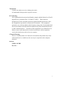
Home
System Uptime: specifies the amount of time, which the system has been up.
This time is reset every time the system is reset.
LAN IP Address: indicates the IP Address of your LAN.
MAC address: MAC address is the address of your MAC.
Security: for your password, which is configured in the “System” section.
Application Code Version: tells the version of the application code which you
are using.
Download Code Version: tells the version of the download code which you are
using.
1
WAN
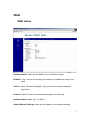
WAN status
Interface Status: these are the details of your interface’s status.
Enabled: “Yes”, lets you know that your interface is enabled and ready to be
used.
Service: either “Routed or Bridged”, tells you the level of your interface’s
connection.
Protocol: refers to how you are transmitting data. (i.e. Ethernet)
Interface Status: either “Up” or “Down”.
Under Network Settings: these are the details of your network settings.
2
Dynamic IP Assignment: “Yes” or “No”, depending on whether or not you are
using a dynamic IP.
IP address: your specified IP.
MAC address: Your specified MAC address.
Subnet Mask: indicates the IP address of your mask.
Default Gateway: is the IP address of the gateway. The gateway IP could be
retrieved from DHCP offer in DHCP mode, or be set up
manually in fixed IP mode.
DNS address: refers to the address of your dynamic name server, if applicable.
VLAN: VLAN tag value encoded in the Ethernet header in all outgoing packets
Priority Tag: Priority Tag value encoded in the Ethernet header in outgoing
packets.
3
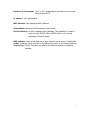
WAN Configuration
1. Device Operating Mode: you choose either “Router” or “Bridged”
depending on your operation.
2. You will check either “Obtain WAN configuration dynamically” or “Specify
fixed WAN configuration”.
When you choose “Obtain WAN configuration dynamically”, the information
is detected automatically through DHCP.
If you choose “Specify fixed WAN configuration”, you are required to enter
the IP address, IP of the Sub mask, IP of the Gateway, and IP of the DNS
Server, if applicable.
3. Multicast Limits:
Broadcast Limit: the value specifies the maximum limit on the percentage of
broadcast packets which will be bridged to the destination
interface (as a percentage of the source side bandwidth)
4
Multicast Limit: the value specifies the maximum limit on the percentage of
multicast packets which will be bridged to the destination
interface (as a percentage of the source side bandwidth)
5
WAN PPPoE Configuration
1. Enable PPPoE: “Yes” or “No”, to enable/disable PPPoE
2. Under “Authentication”, you enter the username and password given by
your ISP.
3. Settings:
Idle Timeout: Idle timeout before PPP connection is closed due to inactivity
Echo Timeout: the duration between PPP echo requests sending to server.
Echo Count: the number of unanswered PPP echo requests before PPP
connection is closed.
Service Name: PPPoE Service name
AC Name: PPPoE AC name
6
IPSec Configuration
This page allows configuration of the device’s IPSec (IP Security) settings.
Enable tunnel 1: Enable/disable tunnel 1 IP sec
Remote IP Address range: start and end of remote IP address range.
Remote security gateway: Remote security gateway IP address
Security Mode: IPSec mode (tunneling/transport)
Outbound AH SPI (DEC): Outbound AH security parameter index number.
Outbound AH Authentication Algorithm: in HMAC-MD5 or HMAC-SHA1
Outbound AH Authentication Key (HEX): hex number up to 40 nibbles
Outbound ESP SPI (DEC): Outbound ESP security parameter index number
Outbound ESP Encryption Algorithm: in 3DES-CBC or DES-CBC
Outbound ESP Authentication Algorithm: in HMAC-MD5 or HMAC-SHA1
Outbound ESP Encryption Key (HEX): hex number up to 48 nibbles
Outbound ESP Authentication Key (HEX): hex number up to 40 nibbles
Inbound AH SPI (DEC): Inbound AH security parameter index number
Inbound AH Authentication Algorithm: in HMAC-MD5 or HMAC-SHA1
7
Inbound AH Authentication Key (HEX): hex number up to 40 nibbles
Inbound ESP SPI (DEC): Inbound ESP security parameter index number
Inbound ESP Encryption Algorithm: 3DES-CBC or DES-CBC
Inbound ESP Authentication Algorithm: in HMAC-MD5 or HMAC-SHA1
Inbound ESP Encryption Key (HEX): hex number up to 48 nibbles
Inbound ESP Authentication Key (HEX): hex number up to 40 nibbles
8
WAN VLAN Configuration
WAN VLAN Tag: VLAN tag for all outgoing packets on interface. The value
should be between 0 and 4094
WAN Priority Tag: Priority tag for all outgoing packets on interface. The value
should be between 0 and 7
9
MAC Spoofing Configuration
WAN MAC Address (Spoofed):
Only available when devices under the router mode. The spoofed MAC
address to be used by the device’s WAN interfaces, the Ethernet address of
the outgoing packets from the WAN interface would be replaced with this
address. If blank, the WAN interfaces will use the value of MAC
10
LAN
LAN Configuration
1. Under “Network Settings”, you enter the IP address and subnet mask of
your network.
2. Multicast Limits:
Broadcast Limit: the value specifies the maximum limit on the percentage of
broadcast packets which will be bridged to the destination
interface (as a percentage of the source side bandwidth)
Multicast Limit: the value specifies the maximum limit on the percentage of
multicast packets which will be bridged to the destination
interface (as a percentage of the source side bandwidth)
11
DHCP Server Configuration
These configuration parameters are for the device’s internal DHCP server.
1. Server Setting: “Yes” or “No”, to enable/disable DHCP
Client IP Address Range: Minimum and Maximum limit on the DHCP IP
address pool
2. Client Network Information
Domain Name: LAN domain name provided to DHCP clients during the
OFFER process.
DNS Server: This statically assigned DNS server IP address will be
provided to clients during the OFFER process.
3. Static Address Assignment
Up to eight static DHCP address assignments can be configured. To add a
static IP assignment, enter the LAN device’s host name (must be unique in the
private network) and/or MAC address. Specify the Internal address to be
assigned and press the "Add" button.
12
Router Configuration
These configuration parameters are for the device’s internal router.
1. Dynamic Routing: Whether or not dynamic routing on TX/RX interfaces is
enabled/disabled.
2. Static Routing
Under “Static Routing”, you can specify your routing path of your internal
network.
13
Port Forwarding Configuration
1. Under “Reserved Ports”, specified are the ports, which cannot be forwarded
to the LAN.
2. Under “Port Forwarding to LAN”, you enter the specifications, which you
will be forwarding to the lan, including port range, protocol(Both, TCP or
UDP), and destination IP address.
Click on “Save NAPT Settings” to save your configurations.
14
LAN VLAN Configuration
LAN VLAN Tag: VLAN tag for all outgoing packets on interface. The value
should be between 0 and 4094
LAN Priority Tag: Priority tag for all outgoing packets on interface. The value
should be between 0 and 7
Click on “Save VLAN Settings”, to save your configurations.
15
SIP
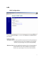
SIP Configuration
1. Under “SIP Server Settings”, you enter the server address, port, domain
name, and expiration time unit, if you choose to send registration request with
an expiration time.
2. Gateway Settings
•
•
Dial Plan: refer to appendix D of this guide
# use as a quick dial function: If this box is checked, the dialed digits
would be sent out when ‘#’ key is pressed.
•
Enable # to be recognized as dial number: allow ‘#’ key to be appeared in
the INVITE request URI
•
Enable * to be recognized as dial number: allow ‘*’ key to be appeared in
the INVITE request URI
•
For the line on the endpoint, enter the Line Phone Number, Caller-ID
Name, signaling port value, authentication Username and Password,
and select if AEC is to be performed on this line.
16
SIP Extensions
1.
2.
Support PRACK method: enable SIP PRACK support.
Encode SIP URI with user parameter: encode user=phone parameter in
SIP URI.
3.
Send INVITE with Timer header: encode Timer header in all INVITE
requests for ringing timeout
4.
5.
SIP session timer: enable SIP session timer function.
Conditional Call Forwarding Timer: Forward the call to the preconfigured number if the phone does not pick up within the timer.
6.
7.
Disable Call Waiting: don’t play call waiting tone.
Disable Caller-ID display: don’t send out caller-id display for
incoming calls.
8.
Call Hold using C=0.0.0.0: using the call hold method described in rfc 2543.
If unchecked, the call hold would follow rfc 3263 method
9.
Send NOTIFY : send out NOTIFY request to transferer for unattended and
attended call transfer.
17
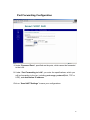
RTP Telephone Event Configuration
This sub-page allows configuration of the out-of-band signaling options for SIP.
Select whether OOB telephone event signaling is to be done using the SIP
INFO message, or to be done via RFC2833 RTP signaling. For additional
information please refer RFC2833.
18
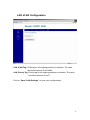
ToS/DiffServ
This sub-page is used to configure the Type-of-Service/Diffserv byte values
which are to be used in the IP header of all transmitted SIP signaling packets
and RTP packets. The ToS/DiffServ byte values are entered as two-digit
hexadecimal values. If no special ToS/DiffServ value is to be used for a
particular traffic type, enter “00” or leave the setting empty.
Press “Save ToS/DiffServ Settings” to save these new settings.
19
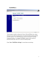
VoIP VLAN Configuration
This sub-page allows configuration of specific VLAN tags that are to be applied
to all SIP signaling and RTP packets used for VoIP calls. These VLAN settings
will override any general VLAN settings applied to the interface
Press "Save VoIP VLAN Settings" to save the settings.
20
CODEC
Audio/CODEC Configuration
1. CODECS: configure the silence suppression to your desired settings.
2. Packetization: configure the packet sending increments.
3. Jitter Buffer: configure the timing of the voice buffering.
Selection between adaptive or fixed jitter buffer. Default = ADAPTIVE
Set the adaptive jitter buffer maximum playout delay. Default = 100ms
or Fixed jitter buffer playout delay. Default = 40ms
Whether or not to automatically switch from an adaptive jitter buffer to a fixed
jitter buffer upon fax/modem tone detection
Click on “Save CODEC Configuration” to save the configurations made.
21
SYSTEM
Set Security Password
Configure a password for the system.
22
Localization
Choose the correct country for a proper impedance match, as well as the NTP
Server, and Time Zone. Check the “Adjust clock for daylight savings”, when
applicable.
Click on “Save Localization Settings”, to save your configurations.
23
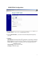
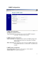
SNMP Configuration
1. SNMP Trap Configuration
IP address: Trap host IP address
Trap Community: The community name used by the SNMP manager to
verify traps. The default value is ‘public’
2. SNMP Community Configuration
Read Community: The community name used by the SNMP manager when
reading SNMP data items from a client MIB. The default
value is ‘public’
Write Community: The community name used by the SNMP manager when
setting SNMP data items in a client’s MIB. The default value
is ‘public’
3. SNMP System Configuration
System Description: Description of the unit (e.g. “John’s phone”)
System Object Id: A vendor’s enterprise ID
24
Service Access Configuration
Check the proper boxes enabling LAN and WAN for the HTTP, SNMP, and VoIP
Discovery.
Click on “Save Service Access Settings”, to save the configurations.
25
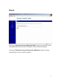
Download
For both HTTP and TFTP methods, the device will reboot itself into the
downloader mode if the main application is executing, and proceed with the
ROM file download and permanent write of the application to the device’s flash
memory. After the download is completed, the download status page will be
displayed.
26
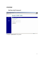
Reset
Chose the “Reset and execute Main Application” option, for execution of the
main application which you have configure, once you reset the system.
Chose the “Reset and execute Downloader Application” option, to being
downloading, once you reset the system.
27
Appendix. Dial Plans
The H.323 and SIP code will allow provisioning (via web browser) of the dial plan. A
dial plan gives the unit a map to determine when a complete number has been entered
and should be passed to the gatekeeper for resolution into an IP address. Dial plans are
expressed using the same syntax as used by MGCP NCS specification.
The formal syntax of the dial plan is described by the following notation:
Digit ::= "0" | "1" | "2" | "3" | "4" | "5" | "6" | "7" | "8" | "9"
Timer ::= "T" | "t"
Letter ::= Digit | Timer | "#" | "*" | "A" | "a" | "B" | "b" | "C" | "c"| "D" | "d"
Range ::= "X" | "x" -- matches any digit
| "[" Letters "]" -- matches any of the specified letters
Letters::= Subrange | Subrange Letters
Subrange::= Letter -- matches the specified letter
| Digit "-" Digit -- matches any digit between first and last
Position::= Letter | Range
StringElement::= Position -- matches any occurrence of the position
| Position "." -- matches an arbitrary number of occurrences
including 0
String ::= StringElement | StringElement String
StringList::= String | String "|" StringList
DialPlan::= String | "(" StringList ")"
A dial plan, according to this syntax, is defined either by a (case insensitive) string or by
a list of strings. Regardless of the above syntax a timer is only allowed if it appears in
the last position in a string (12T3 is not valid). Each string is an alternate numbering
scheme. The unit will process the dial plan by comparing the current dial string against
the dial plan, if the result is underqualified (partial matches at least one entry) then it
will do nothing further. If the result matches or is over-qualified (no further digits could
possibly produce a match) then send the string to the gatekeeper and clear the dial string.
The Timer T is activated when it is all that is required to produce a match. The period of
timer T is 4 seconds. For example a dial plan of (xxxT|xxxxx) will match immediately
if 5 digits are entered, it will also match after a 4 second pause when 3 digits are
entered.
28
Sample Dial Plans
Simple Dial Plan
Allows dialing of 7 digit numbers (e.g. 5551234) or an operator on 0. Dial plan is
(0T|xxxxxxx)
Non-dialed Line Dial Plan
As soon as handset is lifted the unit contacts the gatekeeper (used for systems where
dtmf detection is done in-call). Dial plan is (x.) i.e. match against 0 (or more) digits.
Note: the dot ‘.’
Complex Dial Plan
Local operator on 0, long distance operator on 00, four digit local extension number
starting with 3,4 or 5, seven digit local numbers are prefixed by an 8, two digit star
services (e.g. 69), ten digit long distance prefixed by 91, and international numbers
starting with 9011+variable number of digits.
Dial plan for this is:
(0T|00T|[3-5]xxx|8xxxxxxx|*xx|91xxxxxxxxxx|9011x.T)
29