1
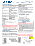
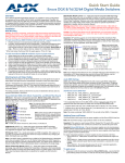
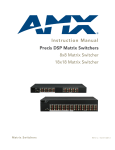
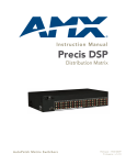
Quick Start Guide
Precis DSP Matrix Switchers
Overview
Applying Power
The Precis DSP is available in two models:
Important: We recommend attaching all power cords to a surge protector and/or an
AC line conditioner.
•
•
FGP37-0808-00P, 8x8 (1 RU)
FGP37-1818-00P, 18x18 (2 RU)
To apply power:
In addition to being a stereo audio router, this product has Digital Signal Processing
(DSP) for the following audio features: volume, tone, balance, 10-band graphic
equalization, and input gain. These features are adjusted by using the APGraphic EQ
software program. APGraphic EQ and the Instruction Manual – Precis DSP Matrix
Switchers (containing complete product documentation, including full specifications for
the system and for the DSP features) are available at www.amx.com.
The Precis DSP supports full Device Discovery through AMX’s AutoPatch Duet
module (firmware v1.2.0 or later is required).
General Specifications
Approvals
CE, FCC Class B, UL, cUL, RoHS
Operational Temperature
32° F to 95° F (0° C to 35° C)
Humidity
0 to 90% non-condensing
AC Power
100 VAC to 240 VAC single phase, 50 Hz to 60 Hz
1.0 A @ 115 VAC max.
0.7 A @ 230 VAC max.
80 Watts
Power Consumption (typical)
45 Watts, fully loaded enclosure
Thermal Dissipation (max.)
273 BTU/hr.
Thermal Dissipation (typical)
154 BTU/hr., fully loaded enclosure
Dimensions
9.75 in. (24.77 cm) depth
19.0 in. (48.26 cm) width with rack ears
17.4 in. (44.20 cm) width without rack ears
2 RU model = 3.5 in. (8.89 cm) height
1 RU model = 1.7 in. (4.32 cm) height
Weight
2.
3.
Attach the power cord to the Precis DSP enclosure and to the power source (turn
on the power source if necessary).
Press the “I” side of the enclosure’s power switch.
The Power Indicator on the front of the enclosure illuminates.
Apply power to the external control device and then to the source and
destination devices.
Establishing Serial Control
(PCs, AMX Control Devices, and Third-Party Controllers)
Installation of the Precis DSP requires a PC to run the APGraphic EQ software.
The Precis DSP can be controlled with APGraphic EQ or with another type
of external control device/system attached to the serial port. Use the pinout in FIG. 3
when connecting the PC (or other serial controller) to the Precis DSP serial port.
General Specifications
Power Consumption (max.)
1.
FIG. 3 RS-232 null modem cable pin diagram, no hardware flow control
To establish external serial control:
1.
Plug a null modem serial cable that matches the pin diagram in FIG. 3 into the
CONTROL (RS-232 / DB-9) port on the enclosure (FIG. 4).
Precis DSP
Serial Port Settings
2 RU model = Approximately 10.5 lb. (4.76 kg)
1 RU model = Approximately 7.0 lb. (3.18 kg)
Baud Rate
Installation
Data Bits
Rack Mounting
Parity
To rack mount a Precis DSP enclosure:
Stop Bits
Flow Control
Insert
Insert
FIG. 1 Attach 2 RU rack ears
1.
2.
Remove and then replace
Attach 1 RU rack ears
Attach the rack ears as shown in FIG. 1 (rack ears and screws provided).
Place enclosure in rack and attach front-mounting screws to hold firmly in place
(we recommend leaving a minimum of one empty rack unit above and below).
Attaching Input and Output Cables
8
None
1
None
FIG. 4 Plug in null modem serial cable
2.
3.
Remove and then replace
9600
Plug the other end of the cable into the serial port on the serial controller/device.
Open the serial communication software and set the port settings to match the
settings in the table in FIG. 4. The settings must match.
Startup with APGraphic EQ
APGraphic EQ software is used during system setup for adjusting the audio DSP
functionality. This software is available at www.amx.com.
PC Requirements for APGraphic EQ (also for APControl 3.0)
• Windows XP Professional® or Windows 2000®
• RS-232 Serial Port
• Minimum Hardware: 166 MHz, 128 MB RAM, 20 MB free disk space*, and
800x600 display
• Recommended Hardware: 2.0 GHz, 512 MB RAM, 20 MB free disk space, and
1280x1024 display
• Java Runtime Environment (JRE): v.1.4.2 is the minimum and recommended
version (JRE v1.4.2 can be installed as part of APGraphic EQ)
* Disk space and RAM details: APGraphic EQ requires 5 MB of disk space once
installed. The installation process requires 20 MB of disk space. If required, the
JRE v1.4.2 packaged with the APGraphic EQ installer will require approximately
200 MB of free disk space for installation and approximately 100 MB once installed.
FIG. 2 Insert RCA plugs into RCA jacks
To attach input and output cables:
1.
Insert RCA plugs into RCA jacks according to labels on the enclosure (FIG. 2).
To install and open the APGraphic EQ program:
Important: Close all other applications currently running on the PC.
1. Download APGraphic EQ program from www.amx.com.
2. Install the program according to the installer instructions.
3. Open the APGraphic EQ program from the location specified during installation
(Start > All Programs > AutoPatch Applications > APGraphicEQ).
Adjusting Volume
VM list
Volume slider
Balance slider
To adjust volume:
Equalization
band sliders
1.
2.
3.
Using the CrossBar, route an input to the output to be adjusted.
From the main interface, select the output from the Output Device list.
Adjust the Volume slider until the desired volume is reached.
Equalization, Balance, and Tone
The 10-band graphic equalizer (see FIG. 5) is used to boost or cut the various
frequencies (bands) for each output. Each equalization band spans one octave and
is identified by its center frequency. The factory setting is for a flat response (0 dB).
The adjustment range for each band is -12 dB to +12 dB.
Note: The Virtual Matrix drop down list has two choices, VM 0 (all) and VM 2 (audio);
either can be used since the Precis DSP has a single (stereo audio) virtual matrix.
To adjust equalization and balance for outputs:
Output device list
Mute
Tone
Reset for flat response
Status bar
1.
2.
3.
4.
5.
Using the crossbar, route an input to all outputs needing adjustment.
From the main interface, select an output from the Output Device list.
Adjust the sliders for each equalization band until the desired sound is achieved.
If necessary – adjust the Balance slider.
Repeat steps for all outputs that require adjustment.
FIG. 5 APGraphic EQ main interface
To adjust tone for outputs:
Normally APGraphic EQ discovers the system when it opens. If it does not do so,
check all connections and then follow the steps below.
1.
2.
Using the crossbar, route an input to the output needing adjustment.
From the main interface, click the Tone button.
To discover the system:
1.
2.
From the Comm menu, select Disconnect.
From the Comm menu, select Settings. Set the correct Comm ID (port) and set
the baud rate to 9600.
3. From the Comm menu, select Connect.
4. From the Options menu, select Rediscover VMs.
If the discovery fails again, contact technical support.
Bass and Treble sliders
Click EQ button to return
to equalization bands
Fine Tuning with APGraphic EQ
Important: To properly adjust the sound for the environment, you will need to route
the signals and adjust the volume as necessary throughout the fine-tuning process.
Routing Signals
To execute switches with the CrossBar:
1.
2.
From the main interface, open Options menu and select Show > CrossBar View.
Click a crosspoint to execute a switch; inputs are on the left and outputs are
across the top. (Click an active crosspoint to disconnect a switch.)
3.
4.
5.
6.
Select an output from the Output Device list.
Adjust the sliders for bass and treble until the desired sound is achieved.
Repeat steps for additional outputs as required.
Click the EQ button to return to the main interface.
Tip: The Tone bands for an output can be set to 0 (flat response) by clicking the reset
button.
Outputs
Startup Control Options
Place cursor over crosspoint to display
input/output numbers for the crosspoint
Although APGraphic EQ has a control view (the CrossBar) available to use during
setup, ongoing control after setup is normally done with one of the following control
options. Switching information is provided for each.
Inputs
AMX Control Devices – The Precis DSP is compatible with a number of AMX
control devices. For control programming information, see the instruction manual for
the specific interface.
Selected (active) crosspoint
FIG. 6 CrossBar showing active crosspoints
APWeb – Connect the APWeb Module (see the APWeb Server Module Quick Start
Guide). For instructions on executing switches, see the Instruction Manual – APWeb.
Adjusting Digital Input Gain
Inputs are set to unity gain at the factory and have a gain adjustment range of
-10 dB to +10 dB.
Important: Make input gain adjustments before outputs are fine-tuned.
To adjust input gain:
1.
2.
3.
4.
5.
APControl 3.0 (PC based) – 1. Install and open the program (contains a Help file).
2. From the APControl Launchbar menu, select System / New; select AutoPatch
Heritage System / Next; select Manual Configuration Entry / Next; enter number of
input and output channels and click Add Virtual Matrix / Next; click Next; select
Define New Communication Settings / Next; click Finish.
3. From the Launchbar menu, select Views / CrossBar > CrossBar View - VM 0.
4. Click on the crosspoints to execute and disconnect switches.
Using the CrossBar, route the input needing adjustment to an output.
From the main interface, open Options menu and select Show > Input Gain
View.
From the Input Device list, select the input just routed.
Adjust the slider until the desired gain level is reached.
Repeat Steps 1 through 4 for all inputs that will be routed to the same output.
Note: The total through-system gain (the amount of input gain plus the amount of
output gain) for any input to output routing path will not exceed +10 dB (automatically
limited by the router).
BCS Commands (terminal emulator) – When power is applied, a short splash
screen appears. Enter BCS commands.
Example: To route Input 1 to Output 2, enter CI1O2T into the terminal emulation
program. When CI1O2T appears, the switch is successful.
Additional Information Covered in Precis DSP Instruction Manual
See the instruction manual at www.amx.com for the following:
•
•
Audio and DSP specifications
Customizing the CrossBar
Reference Document for Precis DSP
The BCS Protocol Instruction Manual (available at www.amx.com) contains BCS
commands for all of the audio DSP features.
For warranty information, see www.amx.com.
10/2013
©2013 AMX. All rights reserved. AMX and the AMX logo are registered trademarks of AMX.
AMX reserves the right to alter specifications without notice at any time.
3000 RESEARCH DRIVE, RICHARDSON, TX 75082 • 800.222.0193 • fax 469.624.7153 • technical support 800.932.6993 • www.amx.com
93-37-858
REV: B