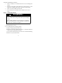
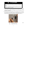
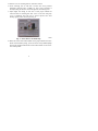
1
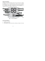
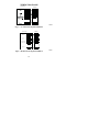
PTACSTAT ---NP---HC,
PTACSTAT ---NP---HP
Installation Instructions
Operating Manual
A07050
Non---Programmable Thermostat
NOTE: Read the entire instruction manual before starting the installation.
2
TABLE OF CONTENTS
PAGE
SAFETY CONSIDERATIONS . . . . . . . . . . . . . . . . . . . . . . . . . . . . . . . . . . . . 3
INTRODUCTION . . . . . . . . . . . . . . . . . . . . . . . . . . . . . . . . . . . . . . . . . . . . . . 4
INSTALLATION CONSIDERATIONS . . . . . . . . . . . . . . . . . . . . . . . . . . . . . . 4
INSTALLATION . . . . . . . . . . . . . . . . . . . . . . . . . . . . . . . . . . . . . . . . . . . . . . . 5
Step 1 — Thermostat Location . . . . . . . . . . . . . . . . . . . . . . . . . . . . . . . . . . . 5
Step 2 — Install Thermostat . . . . . . . . . . . . . . . . . . . . . . . . . . . . . . . . . . . . . . 6
Step 3 — Set Thermostat Configuration . . . . . . . . . . . . . . . . . . . . . . . . . . . 11
Step 4 — Check Thermostat Operation . . . . . . . . . . . . . . . . . . . . . . . . . . . . 16
OPERATING THE THERMOSTAT . . . . . . . . . . . . . . . . . . . . . . . . . . . . . . . 18
TROUBLE SHOOTING . . . . . . . . . . . . . . . . . . . . . . . . . . . . . . . . . . . . . . . . 23
WARRANTY . . . . . . . . . . . . . . . . . . . . . . . . . . . . . . . . . . . . . . . . . . . . . . . . . 25
WIRING DIAGRAMS . . . . . . . . . . . . . . . . . . . . . . . . . . . . . . . . . . . . . . . . . . 30
SAFETY CONSIDERATIONS
Read and follow manufacturer instructions carefully. Follow all local electrical
codes during installation. All wiring must conform to local and national electrical
codes. Improper wiring or installation may damage thermostat.
. When you see
Recognize safety information. This is the safety--alert symbol
this symbol on the equipment and in the instruction manual, be alert to the
potential for personal injury.
Understand the signal words DANGER, WARNING, and CAUTION. These
words are used with the safety--alert symbol. DANGER identifies the most
serious hazards which will result in severe personal injury or death. WARNING
3
signifies a hazard which could result in personal injury or death. CAUTION is
used to identify unsafe practices which may result in minor personal injury or
product and property damage. NOTE is used to highlight suggestions which will
result in enhanced installation, reliability, or operation.
INTRODUCTION
Carrier’s PTAC Comfortt Series non--programmable thermostat is a
wall--mounted, low--voltage thermostat which maintains room temperature by
controlling the operation of a heating and/or air conditioning system. Both heat
pump and air conditioner models are available. A variety of features are provided
including battery operation, memory in case of power interruption, separate
heating and cooling setpoints, backlighting, and built--in installer test.
This Installation Instruction guide and owners manual covers installation,
configuration, start up and operation of the PTAC specific Comfort Series line of
thermostats.
INSTALLATION CONSIDERATIONS
Models
There are two models for the PTAC Comfort Series non--programmable thermostat,
AC and HP versions. The model PTACSTAT--NP--HC--x is designed for AC
systems, controlling one stage of cooling and one stage of heating. It will not operate
a heat pump. Model PTACSTAT--NP--HP--x is designed for HP systems, controlling
one stage of cooling and two stages of heating. The HP thermostat model can be
converted to an AC unit. Select the appropriate model for the intended application.
Power
All Comfort Series models are dual powered. They can operate from batteries
(optional) or 24VAC power. Operation from 24VAC is preferred, if available.
4
Batteries
Battery operation is available for installations where there is no common (C)
wire available at the thermostat. For battery operation, install two alkaline AA
batteries. The thermostat is designed to operate up to one year on a set of
batteries. A battery indicator on the display warns when battery replacement is
needed. If batteries are installed and the thermostat is operated from 24VAC
power, battery operation will occur only when 24VAC power is not present. The
changeover between 24VAC power and battery power is automatic.
For HeatCool system, 5 wires are needed for 24VAC operation and 4 wires are
required for battery operation.
For HP system, 6 wires are needed for 24VAC operation and 5 wires for battery
operation.
When battery operation is used, the C terminal does not need to be connected.
NOTE: Batteries are not required when there are enough wires for proper
operation.
INSTALLATION
Mounting to a horizontal junction box.
For those installations requiring it, mounting hole locations for the
non--programmable are spaced to fit a horizontal junction box.
Step 1 — Thermostat Location
S
S
S
Approximately 5 ft (1.5m) from floor.
Close to or in a frequently used room, preferably on an inside
partitioning wall.
On a section of wall without pipes or duct work.
5
Thermostat should NOT be mounted
S
Close to a window, on an outside wall, or next to a door leading to the
outside.
S
Exposed to direct light or heat from the sun, a lamp, fireplace, or other
temperature--radiating objects which could cause a false reading.
S
Close to or in direct airflow from the unit.
S
In areas with poor air circulation, such as behind a door or in an
alcove.
Step 2 — Install Thermostat
!
WARNING
ELECTRICAL OPERATION HAZARD
Failure to follow this warning could result in personal injury
or death.
Before installing thermostat, turn off all power to equipment.
There may be more than 1 power disconnect. Lock out and
tag switch with a suitable warning label.
1. Turn OFF all power to unit.
2. If an existing thermostat is being replaced:
a. Remove existing thermostat from wall.
b. Disconnect wires from existing thermostat, 1 at a time. Be careful not
to allow wires to fall back into the wall.
c. As each wire is disconnected, record wire color and terminal marking.
d. Discard or recycle old thermostat.
6
!
CAUTION
ENVIRONMENTAL HAZARD
Failure to follow this caution may result in environmental
damage.
Mercury is a hazardous waste. Federal regulations require that
Mercury be disposed of properly.
3. Open thermostat (mounting base) to expose mounting holes. The base
can be removed to simplify mounting. Press the thumb release at the top
of the thermostat and snap apart carefully to separate mounting base from
remainder of thermostat.
4. Route thermostat wires through large hole in mounting base. Level mounting
base against wall (for aesthetic value only—thermostat need not be level for
proper operation) and mark wall through 2 mounting holes. See Fig. 1.
A08093
Fig. 1 -- Backplate Mounting
7
5. Drill two 3/16--in. mounting holes in wall where marked.
6. Secure mounting base to wall with 2 anchors and screws provided
(additional anchoring holes available for more secure mounting, if
needed) making sure all wires extend through hole in mounting base.
7. Adjust length and routing of each wire to reach proper terminal and
connector block on mounting base with 1/4 in. of extra wire. Strip only
1/4 in. of insulation from each wire to prevent adjacent wires from
shorting together when connected. See Fig. 2.
A08094
Fig. 2 -- Secure Wires to Terminal Strip
8. Match and connect wires from the PTAC unit to proper terminals on the thermostat connector blocks (see Fig. 3). Do not remove factory--installed jumper
wire from Rc and Rh terminals. The R wire from the PTAC can be connected to either position.
8
PTAC Terminal
Designations
C
Gl
Gh
OR
O
Y
W
R
R W Y O Gh Gl C
Thermostat Terminal Designations
Rc - 24 VAC, from cooling equipment
OR
Rh - 24 VAC, from heating equipment
O/B
reversing
valve
Not used
or
W - Heating
C - Common 24 VAC
G - Fan
Y - Cooling
A08092
Fig. 3 -- Terminal Designations
9
!
CAUTION
ELECTRICAL OPERATION HAZARD
Failure to follow this caution may result in equipment damage
or improper operation.
Improper wiring or installation may damage the thermostat.
Check to make sure wiring is correct before proceeding with
installation or turning on unit.
9. Push any excess wire into wall and against mounting base. Seal hole in
wall to prevent air leaks. Leaks can affect operation.
10. Snap case back together. Attach thermostat to backplate by inserting tab
on bottom edge and hinging up until top snap secures. See Fig. 4.
A08095
Fig. 4 -- Attach Comfort Series Programmable Thermostat
10
11. Close thermostat assembly making sure pins on back of circuit board
align with sockets in connector.
12. Turn ON power to unit.
When power is applied, all display icons are lit for 2 seconds to test the display.
Following this, the equipment type for which the thermostat is configured is
displayed for an additional 2 seconds. It will be one of PH or PC (if HP, AC, H or C
is displayed, the thermostat is configured incorrectly to operate a PTAC). See
explanation under Step 3, Option 01 below. A heat pump thermostat, configured to
operate a HeatCool unit (see Option 1 below), will display PC. A HeatCool
thermostat cannot be configured to operate a HeatPump unit.
NOTE: If a common wire has not been connected, two AA batteries must be
used to power the thermostat.
Step 3 — Set Thermostat Configuration
Configuration options enable the installer to configure the thermostat for a particular
installation. These must be set correctly to insure proper PTAC operation. Following
is a list of the options available, an explanation of their function, and their factory
default settings.
Configuration Options -- Summary:
Option 01 -- Equipment type
Option 03 -- Fahrenheit/Centigrade
Option 04 -- Unused for PTAC
Option 07 -- Unused for PTAC
Option 10 -- Reversing valve (HP only)
Option 11 -- Minimum deadband between heating and cooling setpoints
Option 13 -- Room air temperature offset adjustment
Option 16 -- Maximum cycles per hour
11
Option 17 -- Time between equipment stages (HP only)
Option 18 -- Continuous backlighting (when 24VAC is supplied only)
Option 26 -- Minimum cooling setpoint
Option 27 -- Maximum heating setpoint
Option 39 -- Display setpoint only (or setpoint and room air)
Option 99 -- Reset to factory defaults
To Enter the Advanced Configuration Mode:
Press and hold the FAN key for about 10 seconds until the display changes so
that only two pairs of digits are showing. The large upper display shows the
configuration number and the small lower shows the configuration setting.
Configuration number will be flashing, which means it can be adjusted using the
UP and DOWN keys. To cause the opposite pair to flash (to be adjustable), press
the MODE key. Successive presses of the MODE key alternate between the
configuration number and the configuration setting. To exit the configuration
mode, press the FAN key. If no key is pressed for 3 minutes, the configuration
mode will automatically exit, returning the thermostat to normal operation (all
previous changes will be saved).
Configuration Options - Selection:
Option 01 -- Equipment type
A PTAC HeatPump thermostat (PTACSTAT--NP--HP--x), valid selections are PH
or PC -- Default is PH.
A PTAC HeatCool thermostat (PTACSTAT--NP--AC--x), the only valid selection
is PC -- Default is PC.
Other selections are available, HP (HeatPump stat only), AC, H or C, but should
not be used as they will not operate your PTAC correctly.
12
Meanings:
PC or PH selects PTAC units (Packaged Terminal Air Conditioners).
PH controls a PTAC with 1 speed heat pump with 1 stage of aux heat.
PC controls a PTAC with 1 speed air conditioner with 1 stage of E1 heat.
NOTE: A PH thermostat can be converted to control a HeatCool system.
Option 03 -- Fahrenheit/Centigrade
Selects temperature measurement units.
Selections:
F = Fahrenheit
C = Centigrade
Default is Fahrenheit
Option 04 -- Not used on a PTAC system
Default = OF
Option 07 -- Not used on a PTAC system
Default = OF
Option 10 -- Reversing valve (HP only)
This selection is only available on heat pump systems. “O/B” terminal can be
configured to be energized in either heating mode or in cooling mode, depending
on heat pump operation.
C — Thermostat output (O/B) will have 24VAC in cooling mode, 0VAC in
heating mode.
H — Thermostat output (O/B) will have 0VAC in cooling mode, 24VAC in
heating mode.
Default is C for PTAC.
13
Option 11 -- Minimum Deadband Between Heating And Cooling
Selections:
01 through 06 — Default is 02.
Sets the minimum allowable number of degrees between heating and cooling
setpoints. One setpoint will “push” the other to maintain this difference.
Option 13 -- Room Air Temperature Offset
Selections:
--5 to 5_ F — Default is 0.
This option selects the number of degrees F to be added to the displayed
temperature to calibrate or deliberately miscalibrate the measured room
temperature.
Option 16 -- Maximum Cycles Per Hour
Selections:
2, 4, or 6 — Default is 4.
The maximum cycle rate is limited by internal timers to the selected number of
cycles per hour. Selection of a higher number causes faster cycling, resulting in
more constant room temperature.
Based on the selection of 2, 4, or 6 cycles per hour, a timer is set to 30, 15, or 10
minutes. This much time must elapse from the start of one cycle before another
cycle can start. For testing, it can be defeated for one cycle by simultaneously
pressing the FAN and UP keys.
If the cycle timer is preventing the equipment from turning on, the display icons
that show the equipment is operating will be flashing to indicate a turn--on delay
is present.
14
Option 17 -- Minimum Time Between Equipment Stages (HP only)
Selections:
10, 15, 20, 25 minutes — Default is 15.
When there are two stages of heat available, this is the amount of time the first
stage must operate before the second stage can turn on. With heat pumps, longer
times can reduce the amount of auxiliary heat used. Not available with AC
thermostats.
Option 18 -- Backlight Configuration
Selections:
ON, OF — Default is OF.
When ON is selected and the thermostat is not battery operated, a low level
continuous display backlight is always on. With OF selected, the backlight is
only on for a short time after a key is pressed.
NOTE: Continuous backlight is not available with battery operation.
Option 26 -- Minimum Cooling Setpoint
Selections:
52_ to 90_F — Default is 62_F.
Sets the lowest cooling setpoint available to the user.
Option 27 -- Maximum Heating Setpoint
Selections:
50_F to 88_F — Default is 83_F.
Sets the highest heating setpoint available to the user.
15
Option 39 -- Display Setpoint Only or Setpoint and Room Temperature
This configuration option determines what the display on the thermostat will
look like.
Selections:
SP — Will display the setpoint only.
rt — Will display the setpoint and room air temperature
Default = SP
Option 99 -- Reset to Factory Defaults
Selection:
See below — There is no default.
Use this capability to reset the thermostat to “out of the box” conditions.
NOTE: All previous configuration settings will be lost!
When this option is selected, the configuration number (99), will appear on the
large upper display and 10 will appear on the lower. To perform the reset, first
use the MODE key to make the 10 flash. Then press and hold the DOWN key.
The 10 will start counting down toward zero. If the DOWN key is kept pressed
until the count reaches zero, the reset will be performed. If the DOWN key is
released early, the number will return to 10 and the reset will not occur.
Step 4 — Check Thermostat Operation
The PTAC Comfort Series non--programmable thermostat has a built--in installer
test capability. Use it to check thermostat and equipment operation without
delays or setpoint adjustments to force heating or cooling.
NOTE: Any time delays or protections built into the equipment will still be
active.
16
To enter the Installer Test mode, use the same process as is used to enter Installer
Configuration, only hold the FAN key longer. More specifically, press and hold
the FAN for about 15 seconds until the display reads In on the left and S in the
smaller display. The MODE will be OFF. The MODE key (upper left) can now
be used to select heat, cool, or emergency heat (HP only). Selecting one of the
available modes will immediately command the equipment to turn on in that
mode. The request will stay active for 3 minutes and then return the mode to off.
With HeatPump thermostats (having 2 stages of heating), the request will be
active for 3 minutes on each stage.
Changing the mode to OFF will terminate any running test immediately.
During any test, the display icons will be displayed the same as for normal
operation of that stage, as follows:
SELECTED MODE
off
cool
heat
Em Heat (HP only)
DISPLAY ICONS
off
cool on
heat on, aux heat on
aux heat on
To terminate the Installer Test mode, press the up or down temperature buttons.
If the thermostat is left in Installer Test mode, it will revert back to normal
operation after 15 minutes.
Checklist
1. Run equipment through several heating and cooling cycles to ensure
proper operation.
2. If the equipment is to be left in operation, setpoints and operating mode
must be properly selected.
3. Put away tools and instruments and clean up debris.
17
OPERATING THE THERMOSTAT
NOTE: Should the thermostat lose power, it will turn back on with the last
settings prior to the power outage.
Button Identification
A08088
Fig. 5 -- Button Identification
a -- FAN Selects whether the fan operates continuously (on) or in cycle mode
(auto)
b -- MODE Selects whether thermostat is set for heating, cooling, emergency
heat (heat pump system only) or off
c -- UP Increases the temperature (or adjusts the screen selection up when setting
advanced programming features)
d -- DOWN Decreases the temperature (or adjusts the screen selection down
when setting advanced programming features)
18
Display backlighting
The display has two levels of lighting, high level and continuous low level. High
level lighting comes on for 10 seconds any time a button is pressed. Continuous
low level lighting is only available if the thermostat is operated from 24VAC. It
is not available with batteries. Continuous low level backlighting is a
configurable option (see configuration settings above).
6
4
7
5
8
3
9
2
10
1
12
11
A08089
Fig. 6 -- On screen indicators
On-- Screen Indicators
1
2
3
Fan mode -- on or auto
Thermostat mode is off
Current Setpoint or Room temperature (if configured to display room temp)
19
4
Thermostat mode is Cool
5
Thermostat mode is Heat
6
Thermostat mode is emergency heat
7
Fahrenheit
8
Celsius
9
Battery strength indicator
10 Aux Heat is On
11 Compressor is On (if flashing, it is waiting to come on)
12 Current setpoint (if configured to display room temp)
Setting the temperatures for heating and cooling
Your thermostat is installed with the heating set at 68_F and the cooling set at
72_F. You can use these or change them so your room is as warm or as cool as
you would like it to be. These steps will hold the temperature where you set it.
1. To change the heating temperature, press the mode button on the left until
the screen says heat.
2. Press the up or down button located on the right side of the display until
you reach the desired temperature.
3. To change the cooling temperature, press the mode button on the left until
the screen says cool.
4. Press the up or down button located on the right side of the display until
you reach the desired temperature.
Using the fan
When the fan is on, it helps distribute air for a more even temperature in all
spaces. You can set the thermostat so the fan runs continuously (on) or only
20
during your heating and cooling cycles (auto mode, sometimes known as cycle
mode).
The thermostat is set at the factory to run automatically as needed (auto). Here’s
how to change the setting so it runs continuously.
1. Press the fan button on the left. The display message will change from
auto fan to fan on.
2. To return the fan to auto mode, press the fan button again. You will see
fan auto on the display.
Using emergency heat (heat pump units only)
Emergency heat is useful when the automatic auxiliary heat system can’t keep up
with demand. (Units with heat pumps use “auxiliary heat” when it’s too cold
outside for the heat pump to heat the space. The display indicator for this is aux
heat on.)
Here’s how to set your thermostat to use emergency heat.
1. Press the mode button repeatedly until you see Em heat in the upper left
of the display.
2. To turn off emergency heat, press the mode button again to select heat,
cool or off.
Turn the unit off
To use the thermostat to turn off the heating and cooling system, press the mode
button on the left repeatedly until the display shows off in the upper left.
Installing or replacing the batteries
NOTE: Remember, batteries are only required if there are not enough wires to
connect a common wire.
21
Two AA batteries should last about one year. When the batteries have lost about
one--third of their power, a battery icon appears on the display (two--thirds of it
will be black). As the batteries get weaker, the icon goes down to one black bar
and then none. When the icon is empty, you will begin to lose thermostat
functions. We recommend that you replace the batteries at the one bar level with
two AA alkaline batteries.
They are located in the back of the thermostat, so you’ll have to remove it from
the wall. Here’s how to replace batteries:
1. Locate the latch at the top of the thermostat. It’s at the center of the top
rim.
2. Press it down. This will disconnect the thermostat from the top of the wall
plate.
3. Remove the thermostat from the wall bracket completely by bringing it
slightly toward you and lifting it up and off the lip on the lower edge of
the wall bracket.
4. You will see the batteries in the lower right corner. Replace the batteries
with two AA alkaline batteries.
5. Put the thermostat back on the wall bracket by lining up the slot on the
bottom edge of the back of the thermostat with the lip on the wall bracket.
You will feel the slot fit over the lip.
6. With the bottom of the thermostat attached to the bottom of the wall
bracket, bring the thermostat back to the wall. Line up the latch at the top
of the thermostat with the corresponding lip on the wall bracket.
7. Lightly push the thermostat toward the wall. When the latch and lip are
lined up properly, you will hear the thermostat snap into place.
22
TROUBLE SHOOTING YOUR THERMOSTAT
What if...
The battery icon is displayed
The battery icon appears on the display only when the battery starts to lose
power. Replace it when one--third of the icon is black. If your thermostat is
battery powered and you wait until the icon is just a silhouette with no black
bars, you will slowly lose thermostat functions until it doesn’t work at all.
“Aux heat on” is displayed (heat pump systems only)
Aux heat on is auxiliary heat. It applies only to the heat pump version. When it is
displayed, it means the unit is heating with the electric heater. This can happen
manually by setting the mode to Em Heat or automatically, if the unit can not
keep up with demand running in heat pump mode.
There is a power outage
If you lose electricity and have batteries installed, the thermostat will continue to
display the indoor temperature because it has a battery backup power source.
This means that even though your heating and cooling system doesn’t work, you
will still be able to monitor the room temperature.
NOTE: With or without batteries, any previous changes to the settings will be
saved when there is a power outage.
My Heat Pump unit is operating in cooling when it should be heating
Most likely, the reversing valve is setup wrong in the advanced configuration.
Check reversing valve option above in the configuration setup.
My Thermostat does not show room temperature
There is an option in the advanced configuration setup to display set point and
room temperature. Check the configuration setup above.
23
There are icons flashing on the thermostat display
There are several internal timers which influence the thermostat’s operation. If a
timer is preventing the equipment from turning on, the display icons which show
the equipment is operating, will be flashing to indicate a turn--on delay is present.
You get a system error message
Here are the possible system error messages and what they mean:
---- The room air sensor reports that the room air temperature is above 150_F or
below --50_F.
E4 The memory has failed and the thermostat will return to the factory settings.
24
THERMOSTAT LIMITED WARRANTY
FOR WARRANTY SERVICE OR REPAIR, YOU MUST
FOLLOW THESE STEPS IN ORDER:
FIRST:
Contact the installer.
SECOND: Contact the nearest distributor. (See telephone yellow pages.)
THIRD: Contact:
Carrier Corporation
PTAC Consumer Relations
P.O. Box 4808
Syracuse, New York 13221
Phone: 1--800--894--6449
Model No.
Unit Serial No.
Date of Installation
Installed by
Name of Owner
Address of Installation
25
LIMITED WARRANTY for THERMOSTAT
Carrier Corporation (hereinafter “Company”) warrants this product against
failure due to defect in material and workmanship under normal use and
maintenance as follows. If a part fails due to defect within five (5) years from the
date of purchase, Company will provide only a new or remanufactured part, at
Company’s sole option, to replace any defective part without charge for the part.
This limited warranty is subject to the provisions, conditions, limitations, and
exclusions listed below and on the reverse (if any) of this document.
LEGAL REMEDIES -- The owner must notify the Company in writing, by
certified or registered letter to Carrier Corporation, PTAC Consumer Relations,
P.O. Box 4808, Syracuse, New York 13221, of any defect or complaint with the
product, stating the defect or complaint and a specific request for repair,
replacement, or other correction of the product under warranty, mailed at least
thirty (30) days before pursuing any legal rights or remedies.
WARRANTY CONDITIONS:
1. The warranty applies only to products remaining in their original
installation location.
2. Installation, use, care, and maintenance must be normal and in accordance
with instructions contained in the Operator’s Manual and Company’s
service information.
3. Defective parts must be returned to the distributor through a registered
servicing dealer for credit.
4. Where a product is installed in a new residence, the date of purchase is the
date the homeowner purchased his or her residence.
26
5. If the date of original purchase cannot be verified, then the warranty
period begins ninety (90) days from the date of product manufacture (as
indicated by the model and serial number).
LIMITATIONS OF WARRANTIES: ALL IMPLIED WARRANTIES AND/OR
CONDITIONS (INCLUDING IMPLIED WARRANTIES OR CONDITIONS
OF MERCHANTABILITY AND FITNESS FOR A PARTICULAR USE OR
PURPOSE) ARE LIMITED TO THE DURATION OF THIS LIMITED
WARRANTY. SOME STATES OR PROVINCES DO NOT ALLOW
LIMITATIONS ON HOW LONG AN IMPLIED WARRANTY OR
CONDITION LASTS, SO THE ABOVE MAY NOT APPLY TO YOU. THE
EXPRESS WARRANTIES MADE IN THIS WARRANTY ARE EXCLUSIVE
AND MAY NOT BE ALTERED, ENLARGED, OR CHANGED BY ANY
DISTRIBUTOR, DEALER, OR OTHER PERSON, WHATSOEVER.
THIS WARRANTY DOES NOT COVER:
1. 1. Any product ordered over the Internet.
2. Any product not installed by a licensed or otherwise qualified HVAC
technician.
3. Labor or other costs incurred for diagnosing, repairing, removing,
installing, shipping, servicing or handling of either defective parts or
replacement parts, or new units.
4. Normal maintenance as outlined in the installation and servicing
instructions or Operator’s Manual, including filter cleaning and/or
replacement and lubrication.
5. Damage or repairs from faulty installation, misapplication, abuse,
improper servicing, unauthorized alteration or improper operation.
27
6. Failure to start due to voltage conditions, blown fuses, open circuit
breakers, or damages due to the inadequacy or interruption of electrical
service.
7. Damage as a result of floods, winds, fires, lightning, accidents, corrosive
environments or other conditions beyond the control of Company.
8. Parts not supplied or designated by Company, or damages resulting from
their use.
9. Products installed outside the U.S.A. or its territories and Canada.
10. Electricity or fuel costs, or increases in electricity or fuel costs from any
reason whatsoever, including additional or unusual use of supplemental
electric heat.
11. ANY SPECIAL INDIRECT OR CONSEQUENTIAL PROPERTY OR
COMMERCIAL DAMAGE OF ANY NATURE WHATSOEVER.
Some states and provinces do not allow the exclusion of incidental or
consequential damages, so the above limitation may not apply to you.
This Warranty gives you specific legal rights, and you may also have other rights
which vary from state to state or province to province.
28
Table 1 shows the thermostat outputs for each available stage of heating or
cooling. It may be useful in checkout or troubleshooting.
Table 1 – Outputs
EQUIPMENT
CONFIGURATION OPTION #1
COOL
STAGE 1
HEAT
STAGE 1
HEAT
STAGE 2
EM HEAT
PC
Y, G
W
--- ---
--- ---
PH
RVS = C (O)
Y, G, O/B
Y, G
Y, G, W
W
PH
RVS = H (B)
Y,G
Y, G, O/B
Y, G, W, O/B
W
--- PTAC
29
WIRING DIAGRAMS
Thermostat
52MPTAC
W
W
Y
G
GL or GH
Rh
R
or
Rc
C
COM
A08096
Fig. 7 -- A/C Thermostat Typical Installation
52MPTAC
Thermostat
Reversing Valve
Heat
O/B
O
W
W
Cool
Y
Y
Fan
G
GL or GH
24VAC Heating
Rh
24VAC Cooling
Rc
Common
C
R
or
COM
A08097
Fig. 8 -- HP Thermostat Typical Installation
30
THERMOSTAT CONFIGURATION RECORD
Configuration Options
Option 01
____
Equipment Type
Option 03
____
Fahrenheit/Centigrade Selection
Option 04
____
Unused for PTAC
Option 07
____
Unused for PTAC
Option 10
____
Reversing Valve
Option 11
____
Minimum Deadband Between Heating and Cooling Setpoints
Option 13
____
Room Air Temperature Offset Adjustment
Option 16
____
Cycles Per Hour
Option 17
____
Time Between Equipment Stages
Option 18
____
Backlight Configuration
Option 26
____
Minimum Cooling Setpoint
Option 27
____
Maximum Heating Setpoint
Option 39
____
Display Setpoint Only or Setpoint and Room Temperature
Option 99
____
Reset to Factory Default Settings
See configuration descriptions in Configuration Options -- Selection section of
manual.
31
Copyright 2008 Carrier Corp. S 7310 W. Morris St. S Indianapolis, IN 46231
Printed in U.S.A.
Edition Date: 03/08
Catalog No:
Manufacturer reserves the right to change, at any time, specifications
and designs without notice and without obligations.
32
PTACSTAT ---NP---01SI
Replaces: NEW