1
HP Virtual Connect for c-Class BladeSystem
Version 4.10
User Guide
Abstract
This document contains user information for HP Virtual Connect version 4.10. This document is for the person who installs, administers, and
troubleshoots servers and storage systems. HP assumes you are qualified in the servicing of computer equipment and trained in recognizing hazards
in products with hazardous energy levels.
Part Number: 736209-001
September 2013
Edition: 1
© Copyright 2013 Hewlett-Packard Development Company, L.P.
The information contained herein is subject to change without notice. The only warranties for HP products and services are set forth in the express
warranty statements accompanying such products and services. Nothing herein should be construed as constituting an additional warranty. HP shall
not be liable for technical or editorial errors or omissions contained herein.
Microsoft® and Windows® are U.S. registered trademarks of Microsoft Corporation.
Adobe® is a registered trademark of Adobe Systems Incorporated.
Contents
Introduction .................................................................................................................................. 8
What's new .............................................................................................................................................. 8
Virtual Connect documentation.................................................................................................................... 9
Virtual Connect overview.......................................................................................................................... 10
HP Virtual Connect Manager........................................................................................................ 13
Configuring browser support .................................................................................................................... 13
Accessing HP Virtual Connect Manager ..................................................................................................... 14
Command Line Interface overview ................................................................................................... 15
Logging on to the HP Virtual Connect Manager GUI .................................................................................... 15
VCM wizards ......................................................................................................................................... 16
HP Virtual Connect Home ......................................................................................................................... 17
About HP Virtual Connect Manager ........................................................................................................... 18
Navigating the HP Virtual Connect Manager GUI........................................................................................ 18
Navigation overview ..................................................................................................................... 18
Tree view ..................................................................................................................................... 18
Menu items ................................................................................................................................... 19
Activity indicator ........................................................................................................................... 20
Virtual Connect domains .............................................................................................................. 21
Understanding Virtual Connect domains ..................................................................................................... 21
Managing domains ................................................................................................................................. 22
Domain Settings (Configuration) screen ............................................................................................ 23
Domain Settings (IP Address) screen ................................................................................................. 25
Domain Settings (Enclosures) screen ................................................................................................. 26
Domain Settings (Backup/Restore) screen ......................................................................................... 29
Domain Settings (Storage Management Credentials) screen ................................................................ 30
Managing SNMP .................................................................................................................................... 32
SNMP overview ............................................................................................................................ 32
Viewing the system log ............................................................................................................................ 48
System Log (System Log) screen ....................................................................................................... 48
System Log (Configuration) screen ................................................................................................... 50
Managing SSL configuration ..................................................................................................................... 51
SSL Certificate Administration (Certificate Info) screen ........................................................................ 51
SSL Certificate Administration (Certificate Signing Request) screen ....................................................... 53
SSL Certificate Administration (Certificate Upload) screen ................................................................... 56
SSH Key Administration screen ....................................................................................................... 57
Web SSL Configuration screen ........................................................................................................ 58
HP BladeSystem c-Class enclosures ............................................................................................... 60
Enclosure serial numbers .......................................................................................................................... 60
Using multiple enclosures ......................................................................................................................... 60
Multiple enclosure requirements ................................................................................................................ 61
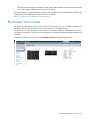
Enclosures View screen ............................................................................................................................ 62
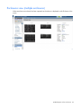
Enclosures view (multiple enclosures) ................................................................................................ 63
Virtual Connect users and roles .................................................................................................... 64
Understanding VC administrative roles ....................................................................................................... 64
Contents
3
Managing users ...................................................................................................................................... 65
Local Users screen ......................................................................................................................... 66
Configuring LDAP, RADIUS, and TACACS+ ...................................................................................... 68
Virtual Connect networks ............................................................................................................. 85
Understanding networks and shared uplink sets........................................................................................... 85
Shared uplink sets and VLAN tagging .............................................................................................. 85
Smart Link..................................................................................................................................... 86
Private Networks ........................................................................................................................... 86
VLAN Tunneling Support ................................................................................................................ 86
Managing networks ................................................................................................................................. 87
Network Access Groups screen ....................................................................................................... 89
Define Network Access Group screen .............................................................................................. 91
Ethernet Settings (Port Monitoring) screen ......................................................................................... 92
Ethernet Networks (Advanced Settings) ............................................................................................ 96
Quality of Service ........................................................................................................................ 101
IGMP Settings (IGMP Configuration) screen .................................................................................... 110
IGMP Settings (Multicast Filter Set) screen ....................................................................................... 114
Define Ethernet Network screen ..................................................................................................... 115
Ethernet Networks (External Connections) screen ............................................................................. 122
Ethernet Networks (Server Connections) screen................................................................................ 123
Managing shared uplink sets .................................................................................................................. 124
Define Shared Uplink Set screen .................................................................................................... 125
Shared Uplink Sets (External Connections) screen ............................................................................ 134
Shared Uplink Sets (Associated Networks) screen ............................................................................ 137
Virtual Connect fabrics .............................................................................................................. 139
Understanding FC fabrics ....................................................................................................................... 139
FabricAttach VC SAN fabrics ........................................................................................................ 139
DirectAttach VC SAN fabrics ........................................................................................................ 142
Mixed FabricAttach and DirectAttach VC SAN fabrics ..................................................................... 144
Bay groups ................................................................................................................................. 145
Double-dense mode ..................................................................................................................... 145
Managing fabrics .................................................................................................................................. 145
Define SAN Fabric screen ............................................................................................................ 146
SAN Fabrics (External Connections) screen ..................................................................................... 153
SAN Fabrics (Server Connections) screen ....................................................................................... 155
Fibre Channel Settings (Misc.) screen ............................................................................................. 156
Virtual Connect server profiles .................................................................................................... 157
Understanding server profiles .................................................................................................................. 157
Multi-blade servers ....................................................................................................................... 159
Flex-10 overview ......................................................................................................................... 160
Flex-10 configuration ................................................................................................................... 162
FlexFabric overview ..................................................................................................................... 163
PXE settings ................................................................................................................................ 164
iSCSI offload and boot ................................................................................................................. 166
iSCSI and FCoE port assignments .................................................................................................. 167
Bandwidth assignment ................................................................................................................. 169
Managing MAC, WWN, and server virtual ID settings .............................................................................. 170
Ethernet Settings (MAC Addresses) screen ...................................................................................... 171
Fibre Channel Settings (WWN Settings) screen ............................................................................... 172
Serial Number Settings screen ....................................................................................................... 173
Advanced Profile Settings ............................................................................................................. 174
Contents
4
Managing server profiles ....................................................................................................................... 175
Define Server Profile screen .......................................................................................................... 175
Server Profiles screen ................................................................................................................... 197
Edit Server Profile screen .............................................................................................................. 198
Assigning a server profile with FCoE connections to an HP ProLiant BL680c G7 Server Blade ............... 205
Unassigning a server profile with FCoE connections to an HP ProLiant BL680c G7 Server Blade and deleting the
SAN fabric ................................................................................................................................. 212
General requirements for adding FC or FCoE connections ................................................................ 216
Virtual Connect and Insight Control Server Deployment .............................................................................. 219
Virtual Connect modules ............................................................................................................ 221
Firmware updates.................................................................................................................................. 221
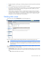
Stacking Links screen ............................................................................................................................. 222
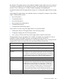
Throughput Statistics screen .................................................................................................................... 223
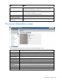
Enclosure Information screen ................................................................................................................... 225
Removing an enclosure ................................................................................................................ 226
Enclosure Status screen .......................................................................................................................... 227
Interconnect Bays Status and Summary screen ........................................................................................... 228
Causes for INCOMPATIBLE status .................................................................................................. 229
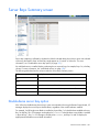
Ethernet Bay Summary (General Information) screen ........................................................................ 230
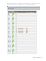
Ethernet Bay Summary (Uplink Port Information) screen ..................................................................... 232
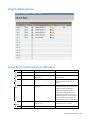
Ethernet Bay Summary (Server Port Information) screen ..................................................................... 233
Ethernet Bay Summary (MAC Address Table) screen ........................................................................ 234
Ethernet Bay Summary (IGMP Multicast Groups) screen .................................................................... 235
Ethernet Bay Summary (Name Server) screen .................................................................................. 236
Ethernet Port Detailed Statistics screen ............................................................................................ 236
FC Port Detailed Statistics screen ................................................................................................... 245
FC Bay Summary screen ............................................................................................................... 247
Interconnect Bay Overall Status icon definitions ............................................................................... 249
Interconnect Bay OA Reported Status icon definitions ....................................................................... 249
Interconnect Bay VC Status icon definitions ..................................................................................... 250
Interconnect Bay OA Communication Status icon definitions.............................................................. 250
Server Bays Summary screen .................................................................................................................. 251
Double-dense server bay option..................................................................................................... 251
Integrity blade devices ................................................................................................................. 254
Server Bay Overall Status icon definitions ....................................................................................... 254
Server Bay OA Reported Status icon definitions ............................................................................... 255
Server Bay VC Status icon definitions ............................................................................................. 255
Server Bay OA Communication Status icon definitions ..................................................................... 256
Server Bay Status screen ........................................................................................................................ 257
Server Bay Status screen - multi-blade servers .................................................................................. 259
Port status conditions ............................................................................................................................. 261
Interconnect module removal and replacement .......................................................................................... 262
Virtual Connect modules ............................................................................................................... 262
Upgrading to an HP Virtual Connect 8Gb 24-Port FC Module ........................................................... 262
Upgrading to an HP Virtual Connect 8Gb 20-Port FC Module ........................................................... 263
Upgrading or removing an HP Virtual Connect Flex-10, HP Virtual Connect FlexFabric, or HP Virtual Connect
Flex-10/10D module ................................................................................................................... 264
Upgrading to an HP Virtual Connect FlexFabric module from a VC-FC module .................................... 266
Onboard Administrator modules .................................................................................................... 266
Maintenance and troubleshooting ............................................................................................... 267
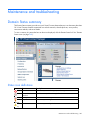
Domain Status summary ......................................................................................................................... 267
Status icon definitions .................................................................................................................. 267
Contents
5
Domain Status screen............................................................................................................................. 268
Module status definitions and causes ....................................................................................................... 269
Export support information...................................................................................................................... 270
Reset Virtual Connect Manager ............................................................................................................... 270
Recovering remote enclosures ....................................................................................................... 271
Server profile troubleshooting ................................................................................................................. 271
Server blade power on and power off guidelines............................................................................. 272
Additional information ........................................................................................................................... 273
Appendix A: Using Virtual Connect with nPartitions ...................................................................... 275
Understanding nPartitions ....................................................................................................................... 275
Assigning a VC profile to an nPar ........................................................................................................... 276
Mapping profile connections......................................................................................................... 276
Reconfiguring nPars ............................................................................................................................... 276
Appendix B: Auto-deployment process ........................................................................................ 278
Overview of the auto deployment process ................................................................................................ 278
DHCP server configuration ............................................................................................................ 278
TFTP server ................................................................................................................................. 280
Importing the enclosure into the domain ................................................................................................... 281
Auto-deployment settings after enclosure import ............................................................................... 282
Starting a deployment operation ............................................................................................................. 282
Viewing deployment information, status, and logs ..................................................................................... 283
The deployment status .................................................................................................................. 284
The deployment log ..................................................................................................................... 286
The deployment configuration file .................................................................................................. 286
Configuration file output ............................................................................................................... 287
Manual TFTP settings ............................................................................................................................. 287
Stopping a deployment operation............................................................................................................ 288
Subsequent deployments (redeployment scenarios) .................................................................................... 288
VC GUI auto-deployment status and settings ............................................................................................. 289
Deployment wait and retry states ............................................................................................................. 289
Waiting for DHCP ....................................................................................................................... 289
Waiting for TFTP ......................................................................................................................... 290
Failed to configure domain ........................................................................................................... 290
Triggering a restart of the deployment process ................................................................................ 290
Configuring file restrictions ..................................................................................................................... 290
TFTP logging and enablement ................................................................................................................. 291
Deployment files logged to the TFTP server ...................................................................................... 291
Appendix C: Using IPv6 with Virtual Connect............................................................................... 292
IPv6 addresses in VC ............................................................................................................................. 292
Link Local Address ....................................................................................................................... 292
DHCPv6 address ......................................................................................................................... 292
EBIPAv6 address ......................................................................................................................... 293
Router advertisement-based addresses ............................................................................................ 293
Domain static addressing ............................................................................................................. 293
Enabling IPv6 support ............................................................................................................................ 293
New installation .......................................................................................................................... 294
Migrations .................................................................................................................................. 295
Disabling IPv6 support ........................................................................................................................... 295
Importing enclosures .............................................................................................................................. 296
VC FW update considerations ................................................................................................................ 296
Upgrading from older versions to VC 4.10 ..................................................................................... 296
Contents
6
Upgrading OA from previous versions to OA 4.00 .......................................................................... 297
VC downgrades to versions older than 4.10 ................................................................................... 297
OA downgrades from OA 4.00 .................................................................................................... 297
Multi-enclosure considerations ................................................................................................................. 297
Limitations ............................................................................................................................................ 297
Acronyms and abbreviations ...................................................................................................... 299
Documentation feedback ........................................................................................................... 303
Index ....................................................................................................................................... 304
Contents
7
Introduction
What's new
The user guide contains information about the following changes in VC 4.10:
•
Manageability enhancements:
o
VC management support for IPv6
IMPORTANT: Use of IPv6 requires OA and iLO from SPP 2013.09.0 (B) or higher SPP releases.
•
o
Ability to hide unused FlexNICs. The FlexNICs (physical functions) that do not map to profile
connections are not enumerated in the OS as network interfaces.
o
Auto-deployment feature, which allows for the configuration of a VC domain from a centralized
location using DHCP and TFTP
o
Improved accommodation of non-HP DACs and FC transceivers. The port status condition "Non-HP"
replaces the "Uncertified" port status condition.
SR-IOV support
o
Ability to enable SR-IOV on certain FLBs and mezzanine cards for Gen8 servers and LOMs for the
HP ProLiant BL620c G7 and HP ProLiant BL680c G7 Server Blades
o
VC SR-IOV supports the following adapters:
— HP Flex-10 10Gb 2-port 530FLB Adapter
— HP FlexFabric 10Gb 2-port 534FLB Adapter
— HP Flex-10 10Gb 2-port 530M Adapter
— HP FlexFabric 10Gb 2-port 534M Adapter
— HP NC552m Flex-10 Adapter
— HP NC553m 10Gb 2-P FlexFabric Converged Network Adapter
— HP FlexFabric 10Gb 2-port 554M Adapter
— HP Flex-10 10Gb 2-port 552M Adapter
— HP FlexFabric 10Gb 2-port 554FLB Adapter
o
VC SR-IOV supports the following operating systems:
— Windows 2012 and higher (64-bit)
— VMware ESXi 5.1 and higher (64-bit)
— RHEL 5.8 and higher (64-bit with KVM)
— RHEL 6.2 and higher (64-bit with KVM)
— SLES 11 SP2 and higher (64-bit with KVM)
•
The following HP products are now supported:
Introduction
8
•
o
The HP ProLiant BL460c Gen8 Server Blade
o
The HP FlexFabric 10Gb 2-port 534FLB Adapter
o
The HP FlexFabric 10Gb 2-port 534M Adapter
o
The HP QMH2672 16Gb FC HBA for BladeSystem c-Class
VCEM compatibility:
o
VCEM requires IPv4 connectivity to manage Virtual Connect.
o
If you are running VCEM 6.3.1 or later to manage a VC 4.10 domain, the 4.10 domain can be in
a VCDG in 3.30 firmware mode or later. To enable new features in VC 4.10, you must upgrade to
VCEM 7.2.2 or later. VCEM 7.2.2 does not support VC versions prior to 3.30.
o
VCEM does not manage VC domains configured for auto-deployment.
o
Configurable role operations must be delegated to one of the following roles if they are to be
performed while the domain is in Maintenance Mode: Network, Storage, or Domain.
Administrators logging into VCM with a Server role account while the domain is in Maintenance
mode will be denied access to perform delegated operations such as exporting support files,
updating firmware, configuring port monitoring, or saving or restoring domain configuration.
o
In VC 4.10, the telemetry port throughput is Enabled by default. You must do the following to add
a fresh VC 4.10 installation to your existing VCDG:
— 3.30-3.70 VCDG with statistics throughput disabled—Clear the Enable Throughput Statistics
check box on the Ethernet Settings (Advanced Settings) screen ("Ethernet Networks (Advanced
Settings)" on page 96), or run the following VCM CLI command:
set statistics-throughput Enabled=false
— 3.30-3.70 VCDG with statistics throughput enabled—Add the domain as is. No change is
required.
o
In VC 4.10, the VLAN Capacity is set to Expanded by default. You must do the following to add a
fresh VC 4.10 installation to your existing VCDG:
— 3.30-3.70 with Legacy VLAN VCDG—You cannot add the domain. Select a different VCDG.
— 3.30-3.70 with Enhanced VLAN VCDG—Add the domain as is. No change is required.
•
A server profile migration of a SAN-booted server between enclosures is not supported for SAN-boot
from a Direct-Attached 3PAR array.
•
The FTP service is disabled by default. The VCSU software temporarily enables it as necessary during
firmware upgrades.
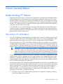
Virtual Connect documentation
The following Virtual Connect documentation is available on the Installing tab of the HP BladeSystem
Technical Resources website (http://www.hp.com/go/bladesystem/documentation):
•
HP Virtual Connect for c-Class BladeSystem User Guide
This guide provides details for the Virtual Connect GUI, including descriptions of screen contents and
steps to set up domains, profiles, networks, and storage.
•
HP Virtual Connect for c-Class BladeSystem Setup and Installation Guide
This guide provides hardware installation and configuration information for initial setup of a Virtual
Connect solution. The guide also provides Virtual Connect module component and LED descriptions
and guidelines for module installation and upgrades.
Introduction
9
•
HP Virtual Connect Manager Command Line Interface for c-Class BladeSystem User Guide
This guide provides information for using the Virtual Connect Command Line Interface, including use
scenarios and complete descriptions of all subcommands and managed elements.
•
HP Virtual Connect Ethernet Cookbook: Single and Multiple Domain (Stacked) Scenarios
This guide helps new Virtual Connect users understand the concepts of and implement steps for
integrating Virtual Connect into a network. The scenarios in this guide vary from simplistic to more
complex while covering a range of typical building blocks to use when designing Virtual Connect
solutions.
•
HP Virtual Connect Fibre Channel Networking Scenarios Cookbook
This guide details the concepts and implementation steps for integrating HP BladeSystem Virtual
Connect Fibre Channel components into an existing SAN fabric. The scenarios in this guide are
simplistic while covering a range of typical building blocks to use when designing a solution.
•
HP Virtual Connect with iSCSI Cookbook
This guide describes how to configure HP Virtual Connect for an iSCSI environment. It provides tips and
troubleshooting information for iSCSI boot and installation.
•
HP Virtual Connect FlexFabric Cookbook
This guide provides users with an understanding of the concepts and steps required when integrating
HP BladeSystem and Virtual Connect Flex-10 or FlexFabric components into an existing network.
•
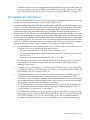
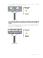
Dual-Hop FCoE with HP Virtual Connect Modules Cookbook
This guide provides concept and implementation details for the Dual-Hop FCoE with HP Virtual Connect
feature, supported on the HP Virtual Connect FlexFabric 10Gb/24-port Module and the HP Virtual
Connect Flex-10/10D Ethernet Module.
•
HP BladeSystem c-Class Virtual Connect Support Utility User Guide
This guide provides instructions for using the Virtual Connect Support Utility, which enables
administrators to upgrade VC-Enet and VC-FC firmware and to perform other maintenance tasks
remotely on both HP BladeSystem c7000 and c3000 enclosures using a standalone, Windows-based,
HP-UX, or Linux command line utility.
•
Release Notes
Release notes document new features, resolved issues, known issues, and important notes for each
release of the Virtual Connect product and support utility.
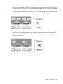
Virtual Connect overview
HP Virtual Connect is a set of interconnect modules and embedded software for HP BladeSystem c-Class
enclosures. VC simplifies the setup and administration of server connections and includes the following
components:
•
VC-Enet modules
o
HP VC Flex-10 10Gb Ethernet Module for BladeSystem c-Class
o
HP VC FlexFabric 10Gb/24-port Module for BladeSystem c-Class, which provides the capability to
configure Ethernet and FC/FCoE or iSCSI connections
o
HP VC Flex-10/10D Module for BladeSystem c-Class
Introduction
10
NOTE: Using a Flex-10 capable NIC with an HP VC Flex-10 or FlexFabric module provides the
ability to divide a 10Gb NIC into four FlexNICs with configurable bandwidth.
•
•
VC-FC modules
o
HP VC 4Gb Fibre Channel Module for BladeSystem c-Class (enhanced NPIV)
o
HP VC 8Gb 24-Port Fibre Channel Module for BladeSystem c-Class
o
HP VC 8Gb 20-Port Fibre Channel Module for BladeSystem c-Class
HP VCM
NOTE: Beginning with VC 4.10, the HP 4GB Virtual Connect Fibre Channel Module is no longer
supported.
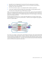
VC implements server edge virtualization between the server and the data center infrastructure so networks
can communicate with individual servers or pools of HP BladeSystem servers. Upgrade, replace, or move
server blades within the enclosures without visible changes to the external LAN and SAN environments. The
external networks connect to a shared resource server pools rather than to individual servers. VC cleanly
separates server enclosure administration from LAN and SAN administration.
VCM is embedded on VC-Enet modules. Access VCM through a web-based GUI or CLI. The Onboard
Administrator provides a web link to the VC GUI. The CLI can be accessed remotely through any SSH session
or through the Onboard Administrator CLI.
The VC modules support the HP BladeSystem c7000 Enclosure, the HP BladeSystem c3000 Enclosure, and
all server blades and networks contained within the enclosure. FlexFabric modules are supported only in
BladeSystem c7000 enclosures with G6 or newer server blades or Integrity i2 and i4 server blades with VC
firmware v3.15 and later.
VC-Enet modules enable connectivity to data center Ethernet switches. VC-Enet modules can also be directly
connected to other types of devices, such as printers, laptops, rack servers, and network storage devices.
The VC-FC and FlexFabric modules enable connectivity of the enclosure to data center FC switches. Every FC
fabric is limited in the number of switches it can support, but the VC-FC modules do not appear as switches
to the FC fabric and do not count against FC fabric limits.
A basic VC domain includes a single HP c-Class BladeSystem c7000 Enclosure for a total of 16 servers (or
up to 32 servers if the double-dense option is enabled), or a single HP c-Class BladeSystem c3000 Enclosure
for a total of 8 servers (or up to 16 servers if the double-dense option is enabled). For more information on
the double-dense option, see "Double-dense server bay option (on page 251)" . Within the domain, any
server blade with the requisite LAN or SAN devices can access any LAN or SAN connected to a VC module,
and a server blade of a given processor type (Integrity or X86) can be used as a spare for any server blade
of the same processor type within the same enclosure, as long as the server has the requisite number and type
of connections. Using the network access groups feature, the network administrator can clearly define a
separation of networks based on their allowed functionality and prevent the server administrator from
assigning specific network combinations in the same server profile.
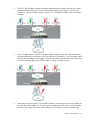
By stacking (cabling) the VC-Enet modules together within the domain and connecting the VC-FC or
FlexFabric module FC uplinks on the same bay of all enclosures to the same FC switch, every server blade in
the domain can be configured to access any external network or fabric connection. With this configuration,
you can use VCM to deploy and migrate a server blade profile to any server in the Virtual Connect domain
without changing external LAN or SAN configurations.
Beginning with VC 4.10, the FTP service on VC-Enet modules is disabled by default. The VCSU software
temporarily enables and disables the FTP service during firmware upgrades of VC-FC modules as needed.
Introduction
11
Each version of VC is tested and supported with one or more SPPs. For a list of supported SPPs that must be
installed, see the VC release notes.
Introduction
12
HP Virtual Connect Manager
Configuring browser support
Access to the VCM GUI is provided through HTTPS (HTTP exchanged over an SSL-encrypted session) and
requires HTTPS (port 443) to be enabled on the management network.
The minimum supported screen resolution is 1024 x 768 with 256 colors. For optimal viewing, HP
recommends setting the screen resolution to 1280 x 1024.
Requirements
The VCM web interface requires an XSLT-enabled browser with support for JavaScript 1.3 or the equivalent.
The following browsers are supported:
•
Microsoft Internet Explorer 9.x and 10.x
•
Mozilla Firefox 17.x ESR and 22.x
Browsers that provide the required functionality but do not appear in the previous list are not prevented from
running the application, but no support is offered for unlisted browsers.
If you receive a notice that your browser does not have the required functionality, examine your browser
settings to ensure they meet the following requirements or contact your administrator.
The use of third-party browser download managers is not supported or recommended when using Virtual
Connect. Using third-party download managers might cause some VC file download functionality to work
incorrectly, for example, when saving the domain configuration, downloading a support information file,
and so on.
The following browser settings must be enabled before running the application:
•
JavaScript
Client-side JavaScript is used extensively by this application. Check the browser settings to make sure
JavaScript is enabled before running the application.
•
ActiveX
When using Microsoft Internet Explorer with this application, ActiveX must be enabled. Check the
browser settings to make sure ActiveX is enabled before running the application.
•
Adobe Flash Player
VC 4.10 requires Adobe Flash Player 11.1 or higher before you can log in. HP recommends updating
to Adobe Flash Player 11.5 or higher for Windows and 11.2 for Linux systems.
The recommended Adobe Flash Player web browser plug-in can be downloaded and installed from the
Adobe website (http://get.adobe.com/flashplayer/), or downloaded as a standalone executable
from the Adobe website (http://www.adobe.com/downloads).
For the latest Adobe Flash Player Security Bulletin Updates, see the Adobe website
(http://www.adobe.com/support/security/index.html#flashplayer).
•
Pop-up windows
HP Virtual Connect Manager 13
Pop-up windows must be enabled for certain features to function correctly. Check the browser settings
to make sure pop-up blockers are not enabled before running the application.
•
Cookies
Cookies must be enabled for certain features to function correctly. Check your browser settings to make
sure cookies are enabled before running the application.
Accessing HP Virtual Connect Manager
Access to VCM occurs over the same Ethernet connection used to access the enclosure Onboard
Administrator and server blade iLO connections.
Access VCM in one of the following ways:
•
If the management network uses dynamic DNS, locate the Default Network Settings label on the
primary VC-Enet module, and then type the DNS name into the address field of the web browser.
If the management network does not use dynamic DNS, use the Onboard Administrator to access VCM.
•
Log on to the enclosure Onboard Administrator. From the rack overview screen, select the Virtual
Connect Manager link from the left navigation tree.
•
Log on to the enclosure Onboard Administrator. To display the Interconnect Bays summary screen,
select Interconnect Bays in the left navigation tree of the Onboard Administrator user interface. Select
the Management URL link for the primary VC-Enet module.
VCM typically operates on the primary VC-Enet module unless that module becomes unavailable,
causing a failover to the backup VC-Enet module. If you cannot connect to the primary VC-Enet module,
try connecting to the management URL for the backup VC-Enet module.
•
Access the VCM CLI remotely through an SSH session by connecting to the VC-Enet module
management IP address.
In a multi-enclosure VC domain, VCM runs on the primary module in the primary enclosure. If both the
primary and backup modules in the primary enclosure fail, are powered off, or are removed, VCM is not
accessible.
HP Virtual Connect Manager 14
Command Line Interface overview
The VCM Command Line Interface can be used as an alternative method for administering the VCM. Using
the CLI can be useful in the following scenarios:
•
You can develop tools that utilize VCM functions for data collection and for executing provisioning and
configuration tasks.
•
When no browser is available or you prefer to use a command line interface, you can access
management data and perform configuration tasks.
•
You can batch commands using script files. These script files can be run manually or scheduled to run
automatically.
For more information, see the HP Virtual Connect Manager Command Line Interface for c-Class BladeSystem
User Guide on the Installing tab of the HP BladeSystem Technical Resources website
(http://www.hp.com/go/bladesystem/documentation).
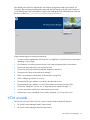
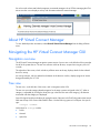
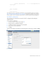
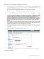
Logging on to the HP Virtual Connect Manager GUI
Log on using the user name (Administrator) and password.
You can optionally specify the authentication method or VCM role at logon.
To specify the authentication method (local, ldap, radius, tacacs), enter the authentication method followed
by a colon before the user name. For example, ldap:user1.
To specify the VCM role (domain, network, server, storage), enter the role followed by a colon before the
user name. For example, network:user1.
For more information on authentication methods and VCM roles, see "Virtual Connect users and roles (on
page 64)."
HP Virtual Connect Manager 15
If the default password for the Administrator user has been changed and needs to be restored, see
information about resetting the administrator password and DNS settings in the HP Virtual Connect for
c-Class BladeSystem Setup and Installation Guide on the Installing tab of the HP BladeSystem Technical
Resources website (http://www.hp.com/go/bladesystem/documentation).
Logon problems might be caused by the following:
•
You have recently upgraded the VCM firmware. You might have to clear the browser cache before
attempting to log on again.
•
The information is not being entered correctly. User names and passwords are case-sensitive.
•
The account being entered is not an account for VCM.
•
The account being entered has been deleted, disabled, or locked out.
•
The password for the account needs to be changed.
•
There is no connection to the primary VC-Enet module running VCM.
•
VCM is undergoing a failover or recovery.
•
The attempted IP sign-in address is not valid for the specified account.
•
The attempted IP sign-in address is for a VC-Enet module not running the primary VCM.
•
The browser settings are incorrect. See "Configuring browser support (on page 13)."
•
You have entered an invalid role or authentication service name.
•
Authentication service is disabled, is not correctly configured, or is not up in the server.
VCM wizards
The first time you log in to the VCM GUI, a series of setup wizards automatically launches:
•
HP Virtual Connect Manager Domain Setup Wizard
•
HP Virtual Connect Manager Network Setup Wizard
HP Virtual Connect Manager 16
•
HP Virtual Connect Manager Fibre Channel Setup Wizard
•
HP Virtual Connect Manager Server Profile Setup Wizard
These wizards can also be launched at any time using the Tools pull-down menu at the top of the GUI.
For more information about the setup wizards, see the HP Virtual Connect for c-Class BladeSystem Setup and
Installation Guide on the Installing tab of the HP BladeSystem Technical Resources website
(http://www.hp.com/go/bladesystem/documentation).
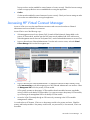
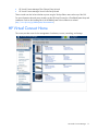
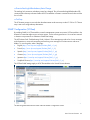
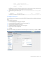
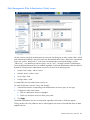
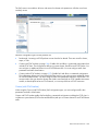
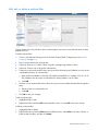
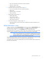
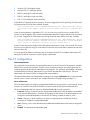
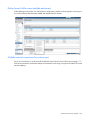
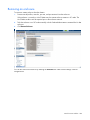
HP Virtual Connect Home
This screen provides access for the management of enclosures, servers, networking, and storage.
HP Virtual Connect Manager 17
If a red icon with a horizontal white bar appears, an external manager such as VCEM is managing the VCM.
Mouse over the icon to display a tool tip with information about the external manager.
About HP Virtual Connect Manager
To view detailed product information, select About HP Virtual Connect Manager from the Help pull-down
menu.
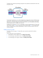
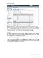
Navigating the HP Virtual Connect Manager GUI
Navigation overview
The HP Virtual Connect Manager navigation system consists of a tree view on the left side of the screen that
lists all of the system devices. The tree view remains visible at all times, except when using any of the VC
wizards.
The right side of the screen, which includes a pull-down menu at the top, displays details for the selected
device or activity.
An activity indicator, which is tethered to the bottom of the browser window, displays progress of actions
being performed by the VC GUI.
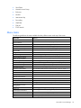
Tree view
The tree view, on the left side of the screen, aids in navigation within VCM.
The tree view provides category-based navigation for the major systems configured within VC. When a
category is expanded (by clicking the white plus sign in the blue box next to the category), all elements
associated with that category are displayed.
Search for logical and physical objects by typing the name of the item in the Find Configuration Items search
field near the top of the screen under Domain Status. Use the following syntax to find objects of a specific
type:
ItemType: ItemName
Valid values for ItemType include:
•
Profile
•
Network
•
Uplink Set
HP Virtual Connect Manager 18
•
SAN Fabric
•
Network Access Group
•
Enclosure
•
Module
•
Interconnect Bay
•
Device Bay
•
IGMP filter
•
Filter set
•
FCoE network
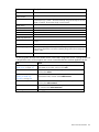
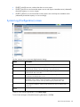
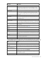
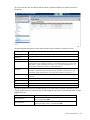
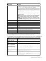
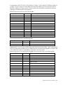
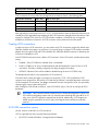
Menu items
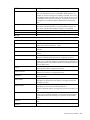
The following table lists the items available from the pull-down menu at the top of the screen.
Menu item
Links to
Define
Ethernet Network
Define Ethernet Network screen (on page 115)
SAN Fabric
Define SAN Fabric screen (on page 146)
Shared Uplink Set
Define Shared Uplink Set screen (on page 125)
Network Access Group
Define Network Access Group screen (on page 91)
Server Profile
Define Server Profile screen (on page 175)
Configure
Domain Settings
Domain Settings (Configuration) screen (on page 23)
Ethernet Network Settings
Ethernet Settings (MAC Addresses) screen (on page 171)
Quality of Service (QoS)
Quality of Service screen (on page 103)
IGMP Settings
IGMP Settings (IGMP Configuration) screen (on page 110)
Fibre Channel Settings
Fibre Channel Settings (WWN Settings) screen (on page 172)
Serial Number Settings
Serial Number Settings screen (on page 173)
Local User Accounts
Local Users screen (on page 66)
Certificate Administration
SSL Certificate Administration (Certificate Info) screen (on page 51)
Tools
Hardware Overview
Enclosures View ("Enclosures View screen" on page 62)
Domain Setup Wizard
Welcome screen for the Domain Setup Wizard
Network Setup Wizard
Welcome screen for the Network Setup Wizard
Fibre Channel Setup Wizard
Welcome screen for the Fibre Channel Setup Wizard
Server Profile Setup Wizard
Welcome screen for the Server Profile Setup Wizard
Throughput Statistics
Throughput Statistics screen (on page 223)
Backup/Restore Domain
Configuration
Domain Settings (Backup/Restore) screen (on page 29)
System Log
System Log (System Log) screen (on page 48)
Export Support Information
Export Support Information (on page 270)
Reset Virtual Connect Manager
Reset Virtual Connect Manager (on page 270)
Help
Table of contents
VC Manager help file table of contents
HP Virtual Connect Manager 19
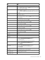
Menu item
Links to
Index
VC Manager help file index
For This Page
Help topic specific to the current page
Virtual Connect Documentation on
hp.com
The Virtual Connect Documentation page on the HP website
(http://www.hp.com/go/bladesystem/documentation)
About HP Virtual Connect Manager
Specific information about this Virtual Connect domain
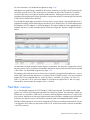
Activity indicator
The GUI displays current activity in a pane attached to the bottom of the browser window, including a
progress bar that displays the activity status graphically. The activity pane includes four controls:
•
Up and down arrow buttons scroll through the recent activity history during the current GUI session.
•
A collapse button temporarily hides the activity pane until the next activity update.
•
A close button hides the activity pane for the current GUI session.
The activity pane is hidden automatically when the activity state is idle. When the activity pane is hidden, a
control appears in the bottom-right corner of the GUI. Click the control to display the activity pane.
Selected long-running VC activities are reported in the activity pane, including:
•
Enclosure Import
•
Enclosure Recovery (after NO-COMM)
•
Enclosure Recovery (after VC restart or failover)
•
Server Profile Operations (create, update, assign and unassign, and delete)
•
Module Recovery
•
Persist Configuration
HP Virtual Connect Manager 20
Virtual Connect domains
Understanding Virtual Connect domains
A basic VC domain includes a single HP c-Class BladeSystem c7000 Enclosure for a total of 16 servers (or
up to 32 servers if the double-dense option is enabled), or a single HP c-Class BladeSystem c3000 Enclosure
for a total of 8 servers (or up to 16 servers if the double-dense option is enabled).
Within the domain, any server blade with the requisite LAN or SAN devices can access any LAN or SAN
connected to a VC module, and a server blade of a given processor type (Integrity or X86) can be used as
a spare for any server blade of the same processor type within the same enclosure, as long as the server has
the requisite number and type of connections.
Using Network Access Groups, the network administrator can define and manage groups of networks,
assigning them to a profile to prevent the use of networks outside of an assigned group.
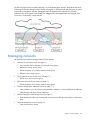
VC supports multiple enclosures, allowing up to four c7000 enclosures to be managed within a single Virtual
Connect domain for a total of up to 128 servers. Multiple enclosure domains are not supported on c3000
enclosures.
By stacking (cabling) the VC-Enet modules together within the domain and connecting the VC-FC or
FlexFabric module FC uplinks on the same bay of all enclosures to the same FC switch, every server blade in
the domain can be configured to access any external network or fabric connection. With this configuration,
you can use VCM to deploy and migrate a server blade profile to any server in the Virtual Connect domain
without changing external LAN or SAN configurations.
The VC domain should be backed up each time changes are made. While the configuration is saved in
non-volatile memory and check-pointed to the horizontally adjacent module, HP recommends saving the
configuration external to the enclosure. See "Domain Settings (Backup/Restore) screen (on page 29)."
When adding VC interconnect modules to a VC-managed enclosure, wait until the modules have been fully
integrated into the current domain and checkpointing is complete before attempting to make configuration
changes to the VC domain. These changes include adding or editing networks, fabrics, profiles, and shared
uplink sets. Verify that the domain status is clear for the newly added interconnect module before making any
changes to the configuration. Modifying the configuration before the integration is complete can cause
unexpected behavior such as incorrect/invalid connections in a profile.
After a configuration is changed and changes have stopped, VCM can take up to 90 seconds to save the
new information to non-volatile storage and an additional minute to checkpoint to the backup module. If
power is removed, the module is reset through the Onboard Administrator interface, or the module is
removed from the enclosure during this update, configuration information might be lost. An icon on the VCM
banner line indicates that the configuration either has not been saved locally, or it has not been
checkpointed.
When a VC-Enet module is powered on or restarted in a VC domain with a large configuration, the module
can take up to 6 minutes to initialize. Management access to this module and to VCM hosted on this module
is available after the initialization completes.
Virtual Connect domains 21
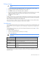
Managing domains
Use the following screens to manage the VC domain:
•
•
Domain Settings (Configuration) screen (on page 23)
o
Change the domain name
o
Delete a domain
o
Configure a customized login screen message
Domain Settings (IP Address) screen (on page 25)
o
•
•
•
Set a domain IP address for the VC domain
Domain Settings (Enclosures) screen (on page 26)
o
View enclosures in the domain
o
Add enclosures to the domain
o
Remove enclosures from the domain
Domain Settings (Backup/Restore) screen (on page 29)
o
Create a backup file of the VC domain configuration
o
Restore a configuration that has been lost
o
Revert to a previously saved configuration
Domain Settings (Storage Management Credentials) screen (on page 30)
o
Add a storage management credential to the domain
o
Remove a storage management credential from the domain
Virtual Connect domains 22
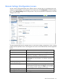
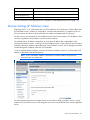
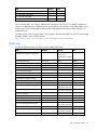
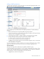
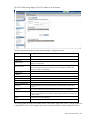
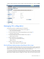
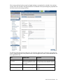
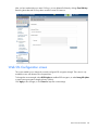
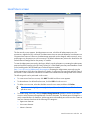
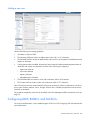
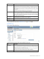
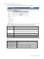
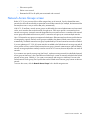
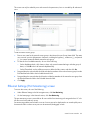
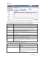
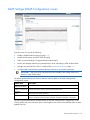
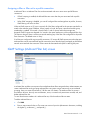
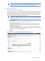
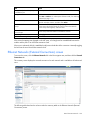
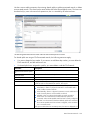
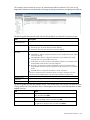
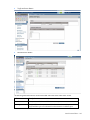
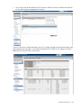
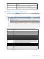
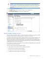
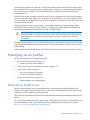
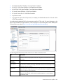
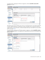
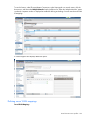
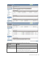
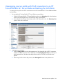
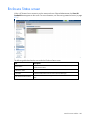
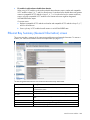
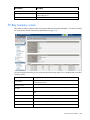
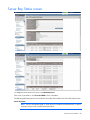
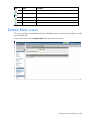
Domain Settings (Configuration) screen
Use this screen to change the domain name, delete a domain, configure and view auto-deployment, and
configure a customized login screen message. To access this screen, click Configuration in the left navigation
tree, or select Domain Settings from the Configure menu. Only users with domain role permissions can make
changes on this screen.
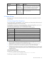
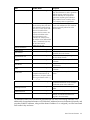
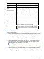
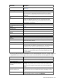
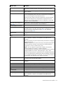
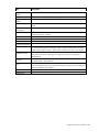
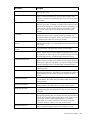
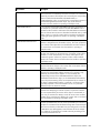
The following table describes the available actions in the Domain Settings (Configuration) screen. Clicking
another link in the pull-down menu or left navigation tree causes current edits that have not been applied to
be lost.
Task
Action
Change the domain name
Enter the revised domain name, and then click Apply.
Display single-dense server bays
Click the checkbox next to the appropriate selection. Available if
double-dense compatibility is selected during import.
Delete a domain
Verify that the correct domain name is displayed, and then click
Delete Domain. For more information, see "Deleting a domain (on
page 24)."
Configure auto-deployment settings and
view auto-deployment status
For more information, see "Auto-deployment (on page 24)."
Add banner text to the login screen
Select the Enable Display of Banner on User Login checkbox, enter a
customized message in the Banner Text field (up to 1500 printable
ASCII characters in length), and then click Apply. Users are required
to acknowledge the banner text before they can log in.
Clear changes and remain on this screen Click Revert.
Click Apply.
Save changes
Virtual Connect domains
23
Deleting a domain
CAUTION: Deleting a domain returns all settings to factory default. This action cannot be
undone.
1.
Power off all servers that are associated with profiles. See "Server Bay Status screen (on page 257)."
2.
Navigate to the Domain Settings (Configuration) screen (on page 23).
3.
Click Delete. A domain name confirmation window is displayed.
4.
Enter the name of the domain to be deleted. This should be the name of the domain you are currently
logged into, displayed in the Virtual Connect Domain Name box on the Domain Settings
(Configuration) screen (on page 23).
5.
Click OK.
If deleting a domain that was using MAC addresses predefined by HP, the administrator should also update
the "Teaming" driver configuration file on the host OS. Otherwise, the driver reinitializes to the saved MAC
address predefined by HP and not the factory default value.
When a VCM domain is deleted, VCM resets VC 8Gb 24-Port FC Modules to a factory default condition.
This operation can take up to 50 seconds per VC 8Gb 24-Port FC Module.
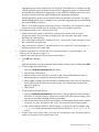
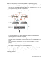
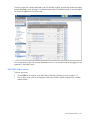
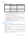
Auto-deployment
The auto-deployment feature allows for the configuration of a VC domain from a centralized location using
DHCP and TFTP to access the configuration script. Auto-deployment is supported only for single-enclosure
domains.
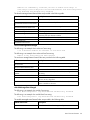
The Auto-Deployment Settings section on the Domain Settings (Configuration) screen (on page 23) allows
you to do the following:
•
Enable or disable auto-deployment.
•
Use DHCP provided TFTP settings or provide your own settings.
•
Start or stop a deployment.
IMPORTANT: Auto-deployment is not supported with an IPv6-only management network
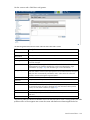
environment.
Task
Action
Use DHCP provided settings
Select (enable) the Use DHCP Provided Settings check box.
Use user-defined TFTP settings
Clear (disable) the Use DHCP Provided Settings check box, and then specify the
TFTP server and configuration file.
Save changes
After you are finished making changes to the settings, click Apply.
Start deployment
Click Start if the button is enabled, and then enter Start in the confirmation
dialog box.
Stop deployment
Click Stop if the button is enabled, and then enter Stop in the confirmation
dialog box.
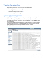
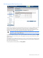
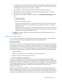
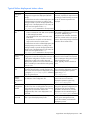
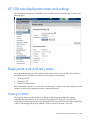
The Auto-Deployment Status section on the Domain Settings (Configuration) screen displays the current
deployment status, the last deployment timestamp, and links to the viewable configuration file, deployment
log, and CLI output.
Virtual Connect domains 24
Task
Action
View the configuration file
Click View next to Configuration File.
View the deployment log
Click View next to Deployment Log.
View the CLI output
Click View next to CLI Output.
For more information on auto-deployment, see "Appendix B: Auto-deployment process (on page 278)."
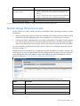
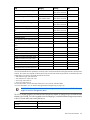
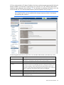
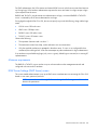
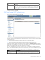
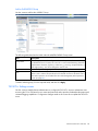
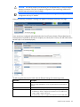
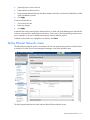
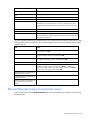
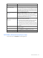
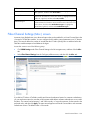
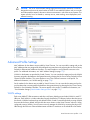
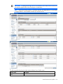
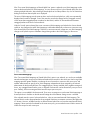
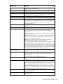
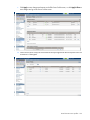
Domain Settings (IP Address) screen
Beginning with VC 4.10, VCM supports the use of IPv6 addresses. IPv6 introduces a 128-bit address that
provides better security, simplicity in configuration, and improved maintenance. To migrate from IPv4 to
IPv6, the network must have an infrastructure that can support and implement the IPv6 protocol.
Use this screen to set a domain IPv4 or IPv6 address for the Virtual Connect domain. This IP address is then
consistent, regardless of which module is primary within the domain.
The optional domain IP address setting allows for a consistent IP address that is independent of the
interconnect module on which it is running. If set, this IP address must be unique within the network and must
be different than the IP address of the module itself. If this IP address is not set, the VC Manager can still be
reached through the IP address of the host VC-Enet module.
To use an optional domain IP address, select the Use Domain IP address check box, and then enter the IP
Address, Subnet Mask, and Default Gateway.
NOTE: Even if a domain IP address is provided, the normal IP address assigned to the
interconnect bay can still be used.
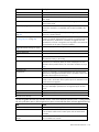
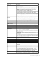
The following table describes the available actions in the Domain Settings (IP Address) screen. Clicking
another link in the pull-down menu or left navigation tree causes current edits that have not been applied to
be lost.
Virtual Connect domains 25
Task
Action
Use a Virtual Connect Domain IPv4 or
IPv6 Address setting
•
•
For IPv4, select the box next to Use Virtual Connect Domain IPv4
Address, and then enter the IPv4 Address, Subnet Mask, and
Gateway.
For IPv6, select the box next to Use Virtual Connect Domain IPv6
Address, and then enter the IPv6 Address and Gateway.
Save changes
Click Apply.
Cancel without saving changes
Click Cancel.
For more information on IPv6, see "Appendix C: Using IPv6 with Virtual Connect (on page 292)."
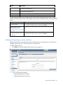
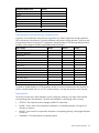
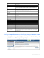
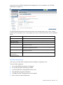
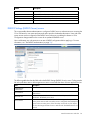
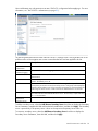
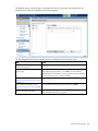
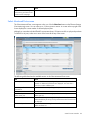
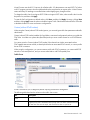
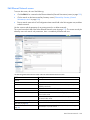
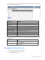
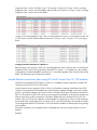
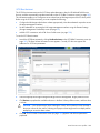
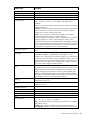
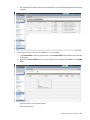
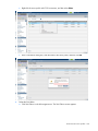
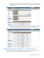
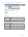
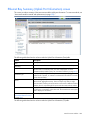
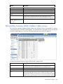
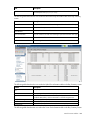
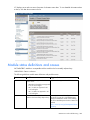
Domain Settings (Enclosures) screen
Use this screen to view, add, or remove enclosures in the domain. When importing an enclosure, consider
the following:
•
After an enclosure import, the VCM CLI shows the Stacking Links Connections Status as "Failed" until all
modules are initialized. Depending on the actual configuration, this can take up to 30 seconds.
•
If an enclosure import is attempted with a server blade in a failed state, VCM might incorrectly report an
error when an error does not exist. If the import times out with an error, close the browser and log in
again to verify that the import was successful. Use the OA to verify the working state of all server blades.
For more information on adding and importing a remote enclosure, see "Adding and importing a remote
enclosure (on page 27)."
Multiple enclosures are supported only if an appropriate primary and backup VC module is running in the
local enclosure. For more information about connecting multiple enclosures, see the HP Virtual Connect for
c-Class BladeSystem Setup and Installation Guide on the Installing tab of the HP BladeSystem Technical
Resources website (http://www.hp.com/go/bladesystem/documentation).
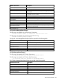
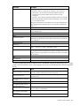
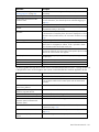
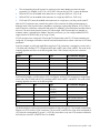
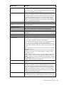
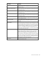
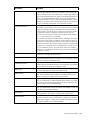
The following table describes the columns within the Domain Settings (Enclosures) screen.
Column
Description
Enclosure ID
Assigned ID of the enclosure
Enclosure Name
Name of the enclosure
Enclosure Serial
Number
Serial number of the enclosure
Rack Name
Name of the rack (assigned through the Onboard Administrator)
Virtual Connect domains 26
Column
Description
OA IPv4 Address
IPv4 IP address of the OA. "Local Enclosure" indicates this enclosure is managed by the
local Onboard Administrator.
OA IPv6 Address
IPv6 IP address of the OA. "Local Enclosure" indicates this enclosure is managed by
the local Onboard Administrator.
Status
Displays whether the enclosure has been imported
Action
Perform import and delete operations.
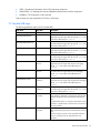
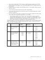
The following table describes the available actions in the Domain Settings (Enclosures) screen. Clicking
another link in the pull-down menu or left navigation tree causes current edits that have not been applied to
be lost.
Task
Action
Import an enclosure
Click the Import link in the Action column, or left-click on the enclosure
row, right-click to display a menu, and then select Import.
Click Find below the table, or right-click inside the table, and then select
Add and import a remote
Find.
enclosure ("Adding and
importing a remote enclosure" on
page 27)
Click the Delete link in the Action column, or left-click on the enclosure
Remove a remote enclosure
("Removing a remote enclosure" row, right-click to display a menu, and then select Delete.
on page 28)
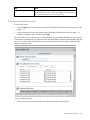
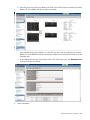
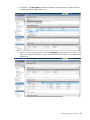
Adding and importing a remote enclosure
Adding and importing a remote enclosure requires domain and server role permissions. Virtual Connect
Manager supports up to four c7000 enclosures in a single domain.
To add a remote enclosure:
1.
Click Find on the Domain Settings (Enclosures) screen (on page 26).
2.
Type in the following information:
o
Onboard Administrator IP Address
o
Onboard Administrator User Name
Virtual Connect domains 27
o
3.
Onboard Administrator Password
Click OK.
IMPORTANT: No more than four enclosures can be found or imported. If an enclosure is
unintentionally found, it can be removed by clicking Delete.
4.
Click the Import link in the Action column.
-orLeft-click on the enclosure row, right-click to display a menu, and then select Import.
Virtual Connect Manager imports the enclosure and provides status information.
Removing a remote enclosure
To remove a remote enclosure, disassociate all profiles, networks, port sets, and port monitors from the
enclosure. If the enclosure is currently in a No-COMM state, the remote enclosure remains in VC Mode. Take
the enclosure out of VC mode manually with the OA command line for that enclosure.
To remove a remote enclosure:
1.
Go to the Domain Settings (Enclosures) screen (on page 26).
2.
Click the Delete link in the Action column.
-orLeft-click on the enclosure row, right-click to display a menu, and then select Delete.
Virtual Connect domains 28
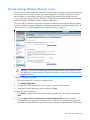
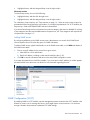
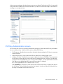
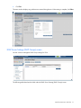
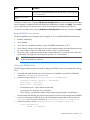
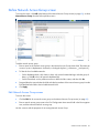
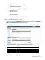
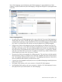
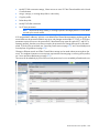
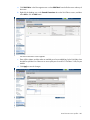
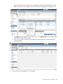
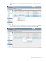
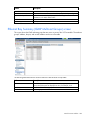
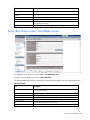
Domain Settings (Backup/Restore) screen
Use this screen to create a backup file of the Virtual Connect domain configuration to restore a configuration
that has been lost, or to revert to a previously saved configuration. The domain configuration includes
network definitions, MAC address settings, WWN settings, Fibre Channel fabric settings, local user
accounts, and server profile definitions. The backup file stores the same information that is check-pointed
between the primary and backup modules during normal operation.
Only users with Save Domain Configuration role operation permissions can perform a backup operation.
Only users with Restore Domain Configuration role operation permissions can perform a domain restore. For
more information, see "Role Management (Role Operations) screen (on page 84)."
CAUTION: To avoid loss of data, do not close the browser window containing the VCM GUI
during backup or restore operations. If the browser window is closed, you must close and then
restart the browser.
To back up a domain configuration:
1.
Enter an encryption key to encrypt the configuration file.
2.
Click Backup Configuration.
3.
Navigate to the hard drive location where you want to save the configuration file.
4.
Name the file (usually the domain name), and then click Save.
To restore a domain configuration:
1.
Click Browse, navigate to the location of the saved configuration file, select the file, and then click
Open.
2.
Select the Ignore enclosure serial number in restored configuration file checkbox to restore a
configuration that was generated on another enclosure. If this item is not selected, a configuration
generated on another enclosure is rejected. This option is relevant to the primary/local enclosure only.
Virtual Connect domains 29
CAUTION: Restoring a Virtual Connect domain configuration from a backup file that was
created on another Virtual Connect domain is not supported and can cause serious faults within
this and other Virtual Connect Domains within the environment. The restore selection and
configuration files should only be used to restore the same previously existing domain.
3.
Select the Ignore firmware version in restored configuration file checkbox to allow restoring a domain
configuration from a backup file that was created using a different version of VC firmware.
IMPORTANT: Restoring a configuration from a backup file saved by firmware version later than
what is currently running is not supported. For example, if you are currently running Virtual
Connect v3.60, you can restore a configuration from a backup file that was created using v3.10
or v3.51, but not v3.70.
4.
Enter the appropriate key if the configuration file is encrypted.
5.
Click Restore Configuration.
6.
Confirm the domain configuration to be restored, and then click OK.
If restoring a configuration file that has multiple enclosures, each remote enclosure must be re-authenticated
for security reasons.
For more information, see "Recovering remote enclosures (on page 271)."
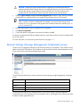
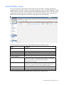
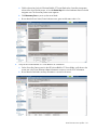
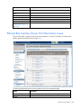
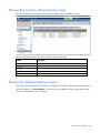
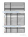
Domain Settings (Storage Management Credentials) screen
Use this screen to manage the credentials of HP P4000 series devices in the domain. The IP address is the IP
address of the LHN CMC interface. This IP address must be accessible from the same management network
where Virtual Connect and Onboard Administrator reside.
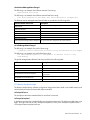
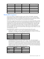
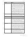
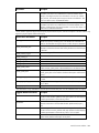
The following table describes the columns within the Domain Settings (Storage Management Credentials)
screen.
Column
Description
Name
Name for the iSCSI storage management
IP address
iSCSI storage management IPv4 address
Username
An administrator for the storage management
Action
Perform edit and delete operations
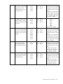
The following table describes the available actions in the Domain Settings (Storage Management
Credentials) screen. Clicking another link in the pull-down menu or left navigation tree causes current edits
that have not been applied to be lost.
Virtual Connect domains 30
Task
Action
Click Add below the table, or right-click inside the table, and then select
Add a credential ("Adding or
editing a credential" on page 31) Add.
Click the Edit link in the Action column, or left-click on the credential row,
Edit a credential ("Adding or
right-click
to display a menu, and then select Edit.
editing a credential" on page 31)
Delete a credential
Click the Delete link in the Action column, or left-click on the credential
row, right-click to display a menu, and then select Delete.
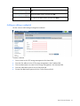
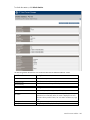
Adding or editing a credential
Use this screen to add a storage management credential.
To add a credential:
1.
Enter a name for the iSCSI storage management in the Name field.
2.
Enter the IPv4 address for the iSCSI storage management in the IP address field.
3.
Enter an administrator user name for the storage management in the Username field.
4.
Enter the administrator password in the Password field.
5.
Re-enter the administrator password in the Confirm Password field.
Virtual Connect domains 31
6.
Click Apply.
Managing SNMP
Use the following screens to manage the domain SNMP configuration:
•
•
SNMP Configuration (VC-Enet) (on page 42)
o
Enable SNMP on VC-Enet modules in the domain
o
Configure SNMP access
o
Add, modify, or delete a trap destination
SNMP Configuration (VC-FC) (on page 45)
o
Enable SNMP on VC-FC modules in the domain
o
Enable SMI-S on VC-FC modules in the domain
o
Configure SNMP access
o
Add, modify, or delete a trap destination
SNMP overview
SNMP is used by network management systems to monitor network-attached devices for conditions that
require administrative attention. SNMP consists of a set of standards for network management, including an
Application Layer protocol, a database schema, and a set of data objects.
The SNMP configuration is controlled by VCM and applies to all modules in the VC domain. The SNMP
agent software residing on a primary module provides access to managed information using SNMP
Virtual Connect domains 32
protocol. The managed information is presented as a hierarchical database called a MIB. Each element of
the managed information is identified by a unique identifier called Object ID. Basic SNMP support is
provided for both VC-Enet modules and VC-FC modules.
Each VC module has an independent SNMP agent that supports a set of MIBs. MIB support for each module
depends both on the type of module (VC-Enet or VC-FC) and the role of the module in the VC domain. A
VC-Enet module can be primary, backup, or subordinate based on its ability to run the VCM. By default, the
SNMP agent is enabled on VC-Enet modules with a read community string of "public."
The VC MIBs are provided in the current HP MIB Kit available for download from the HP website
(http://www.hp.com).
The following restrictions and limitations apply:
•
You must have Administrative privileges to configure SNMP capabilities. The type of privilege required
depends on the item you are configuring.
•
The VCM GUI and CLI do not support configuration of threshold trap parameters (high-water mark,
low-water mark, and averaging period).
•
For Flex-10 connections, threshold traps reflect the state of the entire physical port. These traps are not
generated for individual FlexNICs. For more information on Flex-10 connections, see "Flex-10 overview
(on page 160)."
•
When upgrading from a VC release prior to 3.00, if Fibre Channel SNMP traps were defined with the
DNS type of the Trap Destination address, SNMP settings are not applied to the VC-FC modules upon
completion of the upgrade. To resolve this issue, use the GUI or CLI to edit any FC SNMP trap
destinations that have a DNS name for the trap destination, and change the DNS name to an IPv4
address.
•
VC 3.00 and higher limits the number of FC PortStatus traps you can configure through the CLI to five.
Prior releases did not enforce this restriction. If you have more than five FC PortStatus traps configured
in an earlier version of VC firmware, and then you upgrade to VC 3.00 or higher, then those traps are
retained. Similarly, if you restore a configuration from an earlier version of VC firmware that contains
more than five configured FC PortStatus traps in VC 3.00 or higher, you will have more than the allowed
number of configured FC PortStatus traps. Use caution not to exceed the maximum number of
configured FC PortStatus traps in these scenarios.
The following table provides a list of MIBs and where they are supported. FlexFabric modules support the
Fibre and Fabric MIBs in addition to the Enet MIBs.
MIB
VC-Enet
VC-FC
RFC 2863 IF-MIB
X
—
RFC 4188 Bridge-MIB
X
—
RFC 3418 SNMP v2 MIB
X
X
Compaq System Info MIB
X
X
Compaq Host MIB
X
X
Compaq Rack MIB
—
X*
RFC 1213 Network Mgmt
X
—
RFC 4293 IP-MIB
X
—
Fibre Alliance MIB (FC Mgmt Integ)
—
X
RFC 2837 Fabric Element MIB
—
X
VC Module MIB (VCM-MIB)
X
—
VC Domain MIB (VCD-MIB)
X
—
Virtual Connect domains 33
MIB
VC-Enet
VC-FC
VC LLDP MIB (LLDP-MIB)
X
—
VC LLDPv2 MIB (LLDPv2-MIB)
X
—
VC LACP MIB (LACP-MIB)
X
—
VC QOS MIB (VC-QOS-MIB)
X
—
* Not supported by the HP 8Gb 24-Port FC Module
The VC Module MIB is a VC-specific MIB that describes the state of a specific VC module. In addition to
unique VC module attributes, it defines traps for reporting alerts on port statistics, such as throughput, errors,
and discards. The VC Domain MIB combines domain-wide attributes with traps for state changes in VC
managed objects.
The latest version of the VC-specific MIBs, 9.30 or higher, can be downloaded from the HP Systems Insight
Manager "MIB Kit" site on the HP website
(http://h18006.www1.hp.com/products/servers/management/hpsim/mibkit.html).
SNMP traps
The following table provides a summary of the available SNMP traps.
Trap
Category
Severity
MIB
cpqHoSWRunningStatusChangeTrap
VCM Legacy
connUnitStatusChange
VC-FC Other
CPQHOST-MIB
Corresponds to the
new value of
cpqHoSWRunningStat
us
INFO
FA-MIB
connUnitDeletedTrap
VC-FC Other
INFO
connUnitEventTrap
VC-FC Other
INFO
FA-MIB
connUnitSensorStatusChange
VC-FC Other
CRITICAL
FA-MIB
connUnitPortStatusChange
VC-FC Port Status
See table below
FA-MIB
authenticationFailure¹
VC-FC Other
CRITICAL
SNMPv2-MIB
coldStart
VC-FC Other
CRITICAL
SNMPv2-MIB
cpqHoSWRunningStatusChange
VC-FC Other
INFO
CPQHOST-MIB
authenticationFailure
VC-Enet Other
CRITICAL
SNMPv2-MIB
Domain status change (deprecated)
—
—
—
vcDomainManagedStateChanged
VCM Domain Status
StackingLinkRedundant status change
VCM Domain Status
Module role change
VCM Domain Status
Corresponds to the
VCD-MIB
name of the new state
Corresponds to the
VCD-MIB
name of the new state
INFO
VCM-MIB
Stale checkpoint
VCM Domain Status
WARNING
VCD-MIB
Valid checkpoint
VCM Domain Status
NORMAL
VCD-MIB
—
FA-MIB
Enclosure status change (deprecated)
—
—
vcEnclosureManagedStateChanged
VCM Domain Status
Corresponds to the
VCD-MIB
name of the new state
—
—
3
Network status change (deprecated)
—
vcEnetNetworkManagedStatusChanged VCM Network Status
3
Fabric status change (deprecated)
—
Corresponds to the
VCD-MIB
name of the new state
—
—
Virtual Connect domains 34
Trap
vcFcFabricManagedStatusChanged
3
Category
Severity
MIB
VCM Fabric Status
Corresponds to the
VCD-MIB
name of the new state
—
—
VC module status change (deprecated)
—
vcModuleManagedStatusChanged
Profile status change (deprecated)
VC-Enet Module Status or Corresponds to the
VCD-MIB
VC-FC Module Status
name of the new state
—
—
—
vcProfileManagedStatusChanged3
VCM Profile Status
Physical server change (deprecated)
—
vcPhysicalServerManagedStatusChang
ed3
VCM Server Status
Corresponds to the
VCD-MIB
name of the new state
vcTesttrap
VCM Domain Status
INFO
VCD-MIB
Enet IF-MIB LinkDown
VC-Enet Port Status
INFO
IF-MIB
Enet IF-MIB LInkUp
VC-Enet Port Status
3
Input utilization above high-water mark² VC-Enet Port Threshold
Input utilization below low-water mark² VC-Enet Port Threshold
VC-Enet Port Threshold
Output utilization above high-water
Corresponds to the
VCD-MIB
name of the new state
—
—
NORMAL
IF-MIB
WARNING
VCM-MIB
NORMAL
VCM-MIB
WARNING
VCM-MIB
mark²
Output utilization below low-water
mark²
VC-Enet Port Threshold
NORMAL
VCM-MIB
Input errors above high-water mark²
VC-Enet Port Threshold
WARNING
VCM-MIB
Input errors below low-water mark²
VC-Enet Port Threshold
NORMAL
VCM-MIB
Output errors above high-water mark²
VC-Enet Port Threshold
WARNING
VCM-MIB
Output errors below low-water mark²
VC-Enet Port Threshold
NORMAL
VCM-MIB
vcModPortBpduLoopDetected
VC-Enet Port Status
CRITICAL
VCM-MIB
vcModPortBpduLoopCleared
VC-Enet Port Status
INFO
VCM-MIB
vcModPortProtectionConditionDetected
VC-Enet Port Status
CRITICAL
VCM-MIB
vcModPortProtectionConditionCleared
VC-Enet Port Status
INFO
VCM-MIB
¹ Only supported by the HP VC 8Gb 24-Port FC module
² The VC Module MIB has the capability to send traps when certain bandwidth and throughput utilization thresholds are
reached. The counters are sampled at a fixed interval of 30 seconds and neither sample interval nor threshold values are
configurable in this release. Thresholds are defined as follows:
— Port utilization high water mark 95%
— Port utilization low water mark 75%
— Errors high water mark 5%
— Errors low water mark 1%
For more information, see the description field in the source code for individual MIBs.
3
For more information, see "VC Domain Managed Status Changed traps (on page 38)."
IMPORTANT: During OA failover or other management network disruptions, VC SNMP traps
might not reach the management station.
The VC-FC module generates connUnitPortStatusChange traps based on changes to the connUnitPortStatus
element of the FA-MIB. The following table shows the mapping of connUnitPortStatusChange trap severities
to the VC Domain MIB's trap severity definitions.
connUnitPortStatus value
Severity
unknown
INFO
unused
INFO
Virtual Connect domains 35
connUnitPortStatus value
Severity
ready
NORMAL
warning
WARNING
failure
CRITICAL
nonparticipating
INFO
initializing
INFO
bypass
INFO
ols
MAJOR
other
INFO
Trap categories and required user role permissions
In general, users with domain role permission can perform any SNMP configuration change operations.
Users with network role permission can perform Ethernet configuration change operations, and users with
storage role permission can perform FC configuration change operations. The following table provides a
summary of trap categories and the required administrative privileges.
Trap Category
Domain
Network
Storage
VC-Enet Port Status
X
X
—
VC-Enet Port Threshold
X
X
—
VC-Enet Other
X
X
—
VC-FC Port Status
X
—
X
VC-FC Other
X
—
X
VCM Legacy
X
—
—
VCM Security
X
—
—
VCM Domain Status
X
—
—
VCM Network Status
X
—
—
VCM Fabric Status
X
—
—
VCM Profile Status
X
—
—
VCM Server Status
X
—
—
VCM VC-Enet Status
X
—
—
VCM VC-FC Status
X
—
—
To enable or disable SNMP on a VC-Enet module, domain or network role permissions are required. To
enable or disable SNMP/SMI-S on a VC-FC module, domain or storage role permissions are required.
Trap severities
The severity of traps sent to each destination can be configured, resulting in only traps of the specified
severities being sent to the destination. The levels are listed below in decreasing order of severity:
•
CRITICAL—The component cannot manage installed VC components.
•
MAJOR—One or more of the component's subsystems is not operating properly, causing serious
disruption to functions.
•
MINOR—One or more of a component's subsystems is not operating properly, causing slight disruption
to functions.
•
WARNING—The component has a potential problem.
Virtual Connect domains 36
•
INFO—Operational information on the fully functioning component.
•
UNKNOWN—VC Manager has not yet established communication with the component.
•
NORMAL—The component is fully functional.
Trap severities are only supported for VC-Enet or VCM traps.
VC Module MIB traps
The following table lists traps in the VC Module MIB.
Trap name
Trap data
Description
vcModRoleChange
moduleRole
The VCM role of the module has changed.
vcModInputUtilizationUp
port identification
vcModInputUtilizationDown
port identification
The input line utilization on a port has exceeded its
high-water mark for longer than 30 seconds. port is the
index of the affected port in ifTable.
vcModOutputUtilizationUp
port identification
vcModOutputUtilizationDown port identification
vcModInputErrorsUp
port identification
ifInErrors
vcModInputErrorsDown
port identification
ifInErrors
vcModOutputErrorsUp
port identification
ifOutErrors
vcModOutputErrorsDown
port identification
ifOutErrors
vcModPortBpduLoopDetected port identification
loop status
vcModPortBpduLoopCleared
port identification
loop status
The input line utilization on a port has dropped below its
low-water mark for longer than 30 seconds. port is the
index of the affected port in ifTable.
The output line utilization on a port has exceeded its
high-water mark for longer than 30 seconds. port is the
index of the affected port in ifTable.
The output line utilization on a port has dropped below its
low-water mark for longer than 30 seconds. port is the
index of the affected port in ifTable.
The input error count on a port has exceeded its
high-water mark for longer than the error averaging
period. port is the index of the affected port in
ifTable.
The input error count on a port has dropped below its
low-water mark for longer than the error averaging
period. port is the index of the affected port in
ifTable.
The output error count on a port has exceeded its
high-water mark for longer than the threshold averaging
period. port is the index of the affected port in
ifTable.
The output error count on a port has dropped below its
low-water mark for longer than 30 seconds. port is the
index of the affected port in ifTable.
A network loop condition is detected on this port. If the
loop condition is detected on a Flex10 port, the trap data
indicates the physical port associated with the Flex10
port.
If multiple Flex10 ports on a physical port detect a loop
condition, a separate trap is sent for each occurrence of
the loop condition.
A network loop condition is cleared on this port. The trap
data indicates the physical port associated with a Flex10
port.
For Flex10 ports, this trap is sent only after all Flex10
ports on a physical port are cleared from a loop
condition.
Virtual Connect domains 37
Trap name
Trap data
Description
vcModPortProtectionConditio Port index to the
ifTable (ifIndex)
nDetected
Port index to the
vcModulePortTable
Port protection status
A port protection condition is detected on this port. If the
new port protection status is a value other than OK, the
port may be disabled to protect the VC module from
further service degradation. Administrative action is
required to recover the port from this condition.
vcModPortProtectionConditio Port index to the
ifTable (ifIndex)
nCleared
Port index to the
vcModulePortTable
Port protection status
The port is recovered from port protection condition to
normal operational state.
VC Domain MIB traps
The Virtual Connect vc-domain-mib.mib MIB provides visibility into the various components of a Virtual
Connect Domain.
VC Domain Managed Status Changed traps
This section describes the *ManagedStatus, *Cause, *RootCause, and *ReasonCode OIDs found in each
*ManagedStatusChanged traps in the VC Domain MIB.
The ManagedStatus enumerations (vcDomainManagedStatus, vcEnclosureManagedStatus, and so on) for
all managed status changed objects (vcDomainManagedStatusChanged,
cEnclosureManagedStatusChanged, and so on) are described in the following table.
Managed status
Description
unknown
Indicates the condition of the component could not be determined
normal
Indicates the component is fully functional
warning
Indicates a component threshold has been reached or error condition is imminent
minor
Indicates an error condition exists that has little or no component impact
major
Indicates an error condition exists that significantly impairs the component
critical
Indicates an error condition exists where the component no longer provides service
disabled
Indicates the component is disabled and non-functioning
info
Indicates a non-service affecting condition exists such as initializing components and
system login/logout
•
The Cause string indicates why an object transitioned to the current managed state from the specific
objects perspective. A network failure is an example Cause string.
•
The RootCause string indicates the root causes for an object transitioning managed states. The
RootCause for a network failure could indicate all uplink ports of the network have failed.
•
The ReasonCode provides an object specific reason for the managed state transition. The reason codes
are unique between objects, allowing more specific actions to be taken programmatically from SNMP
management stations.
vcDomainManagedStatusChanged
The following is an example of a domain Cause string:
2 of 7 profiles contain unmapped connections in the domain
The following is an example of a domain RootCause string:
Virtual Connect domains 38
Modules not redundantly connected, failure of module enc0:iobay1 or
enc0:iobay2 or enc1:iobay2 will isolate some modules; Port enc0:iobay5:d3:v1
loop detected and automatically disabled
The domain managed status ReasonCodes are provided in the following table.
Domain reason code
Description
vcDomainOk
All enclosures and profiles are normal in the domain.
vcDomainAbnormalEnclosuresAndProfil One or more enclosures and profiles are abnormal in the domain.
es
At least one enclosure is not OK or Degraded.
vcDomainSomeEnclosuresAbnormal
vcDomainUnmappedProfileConnections The profile contains connections that are not mapped to a server port.
All stacking links between one or more modules have failed.
vcDomainStackingFailed
vcDomainStackingNotRedundant
Some stacking links between one or more modules have failed, but
connectivity still exists between modules.
vcDomainSomeProfilesAbnormal
One or more profiles in the domain are abnormal.
vcDomainUnknown
The condition of the domain cannot be determined.
vcDomainOverProvisioned
More than 16 VC modules are in the domain.
vcEnclosureManagedStatusChanged
The following is an example of an enclosure Cause string:
2 of 6 Ethernet modules are abnormal in enclosure enc0
The following is an example of an enclosure RootCause string:
Module in bay enc0:iobay3 has been removed
The enclosure managed status ReasonCodes are provided in the following table.
Enclosure reason code
Description
vcEnclosureOk
The enclosure is normal.
vcEnclosureAllEnetModulesFailed
All Ethernet modules are abnormal, none are OK or degraded.
vcEnclosureSomeEnetModulesAbnormal One or more Ethernet modules are abnormal.
vcEnclosureSomeModulesOrServersInco The enclosure contains incompatible modules, or configured modules
are missing.
mpatible
vcEnclosureSomeFcModulesAbnormal
One or more FC modules are abnormal.
vcEnclosureSomeServersAbnormal
At least one server is in a known state and no servers are OK, or at
least one server is degraded.
vcEnclosureUnknown
The condition of the enclosure cannot be determined, or the state of
servers or modules is unknown.
vcModuleManagedStatusChanged
The following is an example of a module Cause string:
Port enc0:iobay5:d3:v1 loop detected and automatically disabled
The following is an example of a module RootCause string:
Port enc0:iobay5:d3:v1 loop detected and automatically disabled
The module managed status ReasonCodes are provided in the following table.
Module reason code
Description
vcEnetmoduleOk
The Ethernet module is functioning normally.
Virtual Connect domains 39
Module reason code
Description
vcEnetmoduleEnclosureDown
The module is unable to communicate with the enclosure/OA.
vcEnetmoduleModuleMissing
A configured module has been removed.
vcEnetmodulePortprotect
A condition has been detected on the port causing port protection to
be activated.
vcEnetmoduleIncompatible
The module is incompatible, for example, a configured Enet module
is replaced with an FC module.
vcEnetmoduleHwDegraded
The module is being reported as degraded by the OA.
vcEnetmoduleUnknown
The condition of the module is unknown.
vcFcmoduleOk
The FC module is functioning normally.
vcFcmoduleEnclosureDown
The FC module is unable to communicate with the enclosure/OA.
vcFcmoduleModuleMissing
A configured module has been removed.
vcFcmoduleHwDegraded
The module is reporting a degraded hardware condition.
vcFcmoduleIncompatible
The module is incompatible, such as replacing a configured FC
module with an Enet module.
vcFcmoduleUnknown
The condition of the module is unknown.
vcPhysicalServerManagedStatusChanged
The following is an example of a physical server Cause string:
Server enc0:dev1 unable to communicate with enclosure enc0
The following is an example of a physical server RootCause string:
Server enc0:dev2 profile pending
The physical server managed status ReasonCodes are provided in the following table.
Physical server reason code
Description
vcPhysicalServerOk
The server is functioning normally.
vcPhysicalServerEnclosureDown
The server is unable to communicate with the enclosure/OA.
vcPhysicalServerFailed
The server is in a failed condition.
vcPhysicalServerDegraded
The server is in a degraded condition.
vcPhysicalServerUnknown
The condition of the server is unknown.
vcFcFabricManagedStatusChanged
The following is an example of a FC fabric Cause string:
1 of 2 uplink ports are abnormal on BackupSAN fabric
The following is an example of a FC fabric RootCause string:
1 of 2 uplink ports are abnormal on BackupSAN fabric
The FC fabric managed status ReasonCodes are provided in the following table.
FC fabric reason code
Description
vcFabricOk
The fabric is functioning normally.
vcFabricNoPortsConfigured
The fabric does not have any uplink port configured.
vcFabricSomePortsAbnormal
Some uplink ports for the fabric are in an abnormal condition.
vcFabricAllPortsAbnormal
All uplink ports for the fabric are in an abnormal condition.
vcFabricWwnMismatch
A WWN mismatch condition has been detected.
vcFabricUnknown
The condition of the fabric is unknown.
Virtual Connect domains 40
vcEnetNetworkManagedStatusChanged
The following is an example of an Ethernet network Cause string:
Network BLUE has failed
The following is an example of an Ethernet network RootCause string:
Port enc0:iobay5:X3 is unlinked; Port enc0:iobay5:X4 is incompatible
The Ethernet network managed status ReasonCodes are provided in the following table.
Ethernet network reason code
Description
vcNetworkOk
The network is functioning normally.
vcNetworkUnknown
The condition of the network is unknown.
vcNetworkDisabled
The network is disabled.
vcNetworkAbnormal
The condition of the network is abnormal.
vcNetworkFailed
The network is in a failed condition.
vcNetworkDegraded
The network is in a degraded condition.
vcNetworkNoPortsAssignedToPrivateNetwor No ports have been assigned to the private network.
k
vcProfileManagedStatusChanged
The following is an example of a profile Cause string:
3 TCServer profile connections for server in bay enc0:devbay3 are not mapped
The following is an example of a profile RootCause string:
The TelecomServer profile is assigned to an abnormal server in bay
enc0:devbay1
The profile managed status ReasonCodes are provided in the following table.
Profile reason code
Description
vcProfileOk
The profile is normal.
vcProfileServerAbnormal
The server the profile is assigned to is abnormal.
vcProfileAllConnectionsFailed
All connections in the profile have failed.
vcProfileSomeConnectionsUnmapped
One or more connections in the profile are not mapped to a
physical port.
vcProfileAllConnectionsAbnormal
All connections in profile are abnormal.
vcProfileSomeConnectionsAbnormal
Some connections in the profile are abnormal.
VC domain checkpoint traps
The domain checkpoint trap indicates configuration changes have been saved in non-volatile memory and
copied (check-pointed) to the horizontally adjacent module.
vcCheckpointTimeout
The checkpoint valid status remained false for more than five minutes.
vcCheckpointCompleted
A checkpoint operation has completed following a checkpoint timeout trap. The checkpoint valid status is true
again. This trap is not sent on every checkpoint completion, but only on a checkpoint completion after a
vcCheckpointTimeout trap has been sent.
Virtual Connect domains 41
vcDomainStackingLinkRedundancyStatusChange
The stacking link connection redundancy status has changed. The vcDomainStackingLinkRedundant OID
contained within this trap indicates whether all VC-Enet modules will remain connected to each other with the
loss of a link.
vcTestTrap
The VC domain test trap is received when the administrator sends a test trap via the VC GUI or CLI. The test
trap is sent to all configured trap destinations.
SNMP Configuration (VC-Enet)
By enabling SNMP for VC-Enet modules, network management systems can monitor VC-Enet modules in the
domain for events that might require corrective actions, such as warnings and errors. You must have network
or domain user permissions to administer SNMP Enet settings.
The HP ProLiant Gen8 Troubleshooting Guide, Volume II: Error Messages provides a list of error messages
and information to assist with interpreting and resolving error messages on ProLiant servers and server
blades. To view the guide, select a language:
•
English (http://www.hp.com/support/ProLiant_EMG_v1_en)
•
French (http://www.hp.com/support/ProLiant_EMG_v1_fr)
•
Spanish (http://www.hp.com/support/ProLiant_EMG_v1_sp)
•
German (http://www.hp.com/support/ProLiant_EMG_v1_gr)
•
Japanese (http://www.hp.com/support/ProLiant_EMG_v1_jp)
•
Simplified Chinese (http://www.hp.com/support/ProLiant_EMG_v1_sc)
The VC-Enet SNMP settings apply to all VC-Enet modules in the Virtual Connect domain.
The following table describes the fields within the SNMP Configuration screen.
Virtual Connect domains 42
Field name
Description
Enable SNMP
Select to enable SNMP.
System Contact
Specify a contact name for this system when SNMP is enabled.
Read Community
Controls SNMP read access when SNMP is enabled. The default value for read
community string is "public". The read community string must always be set when
SNMP is enabled. The maximum length is 39 characters.
SNMP Access
Table of networks that are allowed SNMP access
IP Address
IPv4 or IPv6 address for the allowed network
Network Mask Bits
Network mask bits for the allowed network
Type
Type of network
Action
Perform add and delete actions
SNMP Trap Destinations
SNMP trap destination table
Destination
User-designated name for the trap destination. The Destination name must be
unique.
IP Address
IPv4 or IPv6 address or DNS name for the trap destination
Community String
The Community String acts like a password for a given trap destination. The
trap-receiving application can use the community string to filter the incoming traps.
Default: public
Action
Perform edit and delete operations
The following table describes the available actions in the SNMP Configuration screen. Clicking another link
in the pull-down menu or left navigation tree causes current edits that have not been applied to be lost.
Task
Action
Add SNMP access ("Adding
SNMP access" on page 45)
Click Add below the SNMP Access table, or right-click on the header row
of the SNMP Access table, and then select Add.
Delete SNMP access
Click Delete in the Action column, or right-click on the SNMP Access row,
and then select Delete.
Add an SNMP trap destination
("Adding an SNMP trap
destination" on page 44)
Click Add below the destination table, or right-click on the header row of
the destination table, and then select Add Destination.
Edit an SNMP trap destination
Click Edit in the Action column, or right-click on the trap destination row,
and then select Edit Destination.
Delete an SNMP trap destination Click Delete in the Action column, or right-click on the trap destination
row, and then select Delete Destination.
Save changes
Click Apply.
Virtual Connect domains
43
Adding an SNMP trap destination
To add an SNMP trap destination, right-click the header row of the SNMP Trap Destination table, or click
Add at the bottom of the SNMP Trap Destination table.
You can configure up to five VC-Enet and five VC-FC SNMP trap destinations. To add an SNMP trap
destination:
1.
Enter a unique name for the new trap being added. No spaces are allowed.
2.
Select the correct radio button, and then enter the IPv4 address, IPv6 address, or DNS name for the trap
destination. DNS is not supported for VC-FC modules.
3.
Select the Trap Format: SNMPv1 or SNMPv2. SNMPv2 is not supported for VC-FC modules.
4.
Enter the SNMP trap community string for the specified trap. The default is "public."
For VC-Enet modules, the maximum trap community string length is 39.
For VC-FC modules, the maximum trap community string length is 24.
5.
Click OK to save the information and return to the main SNMP configuration screen, or continue and
select trap categories or trap severities.
If you enter information that is invalid (for example, if you use a space in the Destination name), a red box
appears around that field. Hover the mouse over the box to see information regarding the error.
Select trap categories
Selecting a trap category allows multiple traps to be enabled or disabled as a group.
To select trap categories, click the check box. For VC-FC modules, selecting either the Port Status or Other
check box results in all SNMP traps being sent to the trap destination. VC-FC modules do not differentiate
between trap types. To select a VCM trap category, do one of the following:
•
Highlight the item, and then click the right arrow.
Virtual Connect domains 44
•
Highlight the item, and then drag and drop it into the right window.
Select trap severities
To select a trap severity, do one of the following:
•
Highlight the item, and then click the right arrow.
•
Highlight the item, and then drag and drop it into the right window.
For a definition of trap severities, see "Trap severities (on page 36)." When an event causes a trap to be
generated with the severity listed in the right window, it is sent to the trap destination. For VC-FC modules, the
trap severity is fixed at INFORMATIONAL and cannot be modified.
If you do not have the required user role permission to select a category, that section is disabled. For a listing
of trap categories and the required administrative role permission, see "Trap categories and required user
role permissions (on page 36)."
Adding SNMP access
By configuring addresses on the SNMP Access screen, administrators can control which SNMP clients
receive responses from VCM when they query for SNMP information.
To add an SNMP access, right-click the header row of the SNMP Access table, or click Add at the bottom of
the SNMP Access table.
1.
Enter a unique IP address for the network to be given access:
a. Select the IPv4 or IPv6 radio button.
b. Enter the IP address, including a valid network mask bits value (1-32).
2.
Click OK to save the information and return to the main SNMP configuration screen.
If you enter information that is invalid (for example, if you use a space in the IP address), a red box appears
around that field. Hover the mouse over the box to see information regarding the error.
SNMP Configuration (VC-FC)
By enabling SNMP for VC-FC modules, network management systems can monitor the VC-FC modules in the
domain for events, such as warnings and errors, which might require corrective actions. You must have
storage or domain role permission to administer FC SNMP settings.
Virtual Connect domains 45
The VC-FC SNMP settings apply to all VC-FC modules in the VC domain.
The following table describes the fields within the SNMP Configuration screen.
Field name
Description
Enable SNMP
Select to enable SNMP.
Enable SMI-S
Select to enable SMI-S.
System Contact
Specify a contact name for this system when SNMP is enabled. The maximum
length is 20 characters.
Read Community
Controls SNMP read access when SNMP is enabled. The default value is "public".
The read community string must always be set when SNMP is enabled. The
maximum length is 24 characters.
SNMP Access
Table of networks that are allowed SNMP access
IP Address
IPv4 or IPv6 address for the allowed network
Network Mask Bits
Network mask bits for the allowed network
Type
Type of network
Action
Perform add and delete actions
SNMP Trap Destinations
SNMP trap destination table
Destination
User-designated name for the trap destination. The Destination name must be
unique.
IP Address
IPv4 or IPv6 address for the trap destination. DNS name is not supported.
Community String
The Community String acts like a password for a given trap destination. The
trap-receiving application can use the community string to filter the incoming traps.
Default: public
Format
Format of the new trap (SNMPv1)
Action
Perform edit and delete operations
The following table describes the available actions in the SNMP Configuration screen. Clicking another link
in the pull-down menu or left navigation tree causes current edits that have not been applied to be lost.
Virtual Connect domains 46
Task
Action
Add SNMP access ("Adding
SNMP access" on page 45)
Click Add below the SNMP Access table, or right-click on the header row
of the SNMP Access table, and then select Add.
Delete SNMP access
Click Delete in the Action column, or right-click on the SNMP Access row,
and then select Delete.
Add an SNMP trap destination
("Adding an SNMP trap
destination" on page 44)
Click Add below the destination table, or right-click on the header row of
the destination table, and then select Add Destination.
Edit an SNMP trap destination
Click Edit in the Action column, or right-click on the trap destination row,
and then select Edit Destination.
Delete an SNMP trap destination Click Delete in the Action column, or right-click on the trap destination
row, and then select Delete Destination.
Save changes
Click Apply.
SMI-S overview
The SMI-S was created by SNIA to standardize storage management solutions. SMI-S replaces multiple
disparate managed object models, protocols, and transports with a single object-oriented model for each
type of component in a storage network. SMI-S enables management applications (such as HP SIM) to
support storage devices from multiple vendors quickly and reliably because they are no longer proprietary.
SMI-S detects and manages storage elements by type, not by vendor.
You must have storage or domain user role permissions to configure SMI-S capabilities.
The ability to enable or disable SMI-S is not available on the HP VC 8Gb 24-Port FC module.
For the HP VC 8Gb and 4Gb 20-port FC modules, SMI-S is supported. Valid parameters include:
•
Port: 5989
•
Namespace: /root/interop
•
Credentials: Administrator/password on the tag attached to the module
•
Supported CIM classes:
o
CIM_ComputerSystem
o
CIM_FCPort
o
CIM_Location
o
CIM_SoftwareIdentity
o
CIM_Product
o
CIM_PhysicalPackage
o
CIM_FCPortCapabilities
o
CIM_FCPortSettings
o
CIM_FCSwitchSettings
o
CIM_RemoteSeviceAccessPoint
o
CIM_SettingData
o
CIM_Namespace
o
CIM_ConnectivityCollection
Supported CIM clients have no restrictions.
Virtual Connect domains 47
Viewing the system log
Use the following screens to view and configure domain system log information:
•
System Log (System Log) screen (on page 48)
o
•
View logged information events within VCM
System Log (Configuration) screen (on page 50)
o
View remote log destination settings
o
Set remove log destination settings
System Log (System Log) screen
The System Log screen displays logged information of events within Virtual Connect Manager. For more
information about the log entries, see "System Log entry format (on page 49)."
To access the System Log screen, click System Log in the left navigation tree, or select System Log from the
Tools pull-down menu.
Events are logged with the most recent event displayed at the end of the list. Use the scroll bar on the right of
the screen to scroll through the list if it is longer than the display box. When the log reaches maximum
capacity, the oldest logged event is automatically deleted as new events are added.
Click Refresh to display the most current information.
Virtual Connect domains 48
System Log entry format
A wide variety of events are generated by Virtual Connect and logged into the System Log, or SysLog. The
remote logging capability is supported using the syslog protocol defined in RFC 3164. The remote logging
feature also provides an option for transmission over TCP and secure transmission support using stunnel. The
events generated by Virtual Connect follow the same format and contain a time stamp, the Virtual Connect
object information that generated the event, and a detailed message.
The System Log entries use the following format:
[Date in RFC 3164 or ISO 8601 format]T[Time][Time zone] [hostname]
[processname] [[ObjectShortName]:[ObjectName]:[EventCode]:[Severity]]
[Event Message]
In the following example:
2011-07-28T13:57:40-05:00 VCEFXTW210600WH vcmd:
[VCD:aus-c7000-82_vc_domain:1011:Info] VCM user logout :
[email protected]
•
The date is 2011-07-28.
•
The time is 13:57:40.
•
The time zone is -05:00. The time zone includes daytime savings.
•
The hostname is VCEFXTW210600WH.
•
The process name that created the log is vcmd.
•
The object short name is VCD (domain).
•
The object name is aus-c7000-82_vc_domain.
•
The event code is 1011.
•
The event severity is Info (informational).
•
The event message is VCM user logout : [email protected].
The following table describes the Virtual Connect managed objects that are capable of generating System
Log events, along with the corresponding event ID ranges.
VC object name
Object short name
Event ranges
Domain
VCD
1000 – 1999
Enclosure
ENC
2000 – 2999
Ethernet Modules
ENET
3000 – 3999
FC Modules
FC
4000 – 4999
Servers
SVR
5000 – 5999
Profiles
PRO
6000 – 6999
Ethernet Network
NET
7000 – 7999
FC Fabric
FAB
8000 – 8999
Unknown Module
UNK
9000 – 9999
Network Access Groups
NAG
12000 – 12999
The event severity reflects the functional state of the Virtual Connect object. The event severities include:
•
SEVERITY_INFO–A low-level condition for out-of-service equipment, system login/logout, and other
non-service affecting information
•
SEVERITY_WARNING–A threshold was reached or an error condition is imminent
Virtual Connect domains 49
•
SEVERITY_MINOR–An error condition that has no service impact
•
SEVERITY_MAJOR–A critical event that impairs service and requires immediate action (substantially
diminished capacity or a service outage)
•
SEVERITY_CRITICAL–A critical event that severely impairs service and requires immediate action
(substantially diminished capacity or a service outage)
System Log (Configuration) screen
Use this screen to view or set remote log destination settings.
Column
Description
Log host
The IP address or the DNS of the configured remote log destination
Log severity
Severity of the log messages that should be sent to the specified destination. Valid
values include "Critical", "Error", "Warning", and "Informational".
Transport
The transport protocol to be used for sending the log messages to the destination. Valid
values include "TCP" and "UDP".
Port
The port to be used on the destination to send the log messages. Valid values include
1 to 65536. The default value is 514.
Security
Secure transmission of the log messages. Valid values include "None" and "STunnel".
The default value is "None", and no encryption is used during transmission.
The "STunnel" option can be used only if the transport protocol used is TCP.
Date Format
The timestamp format for the log messages. Valid values include "RFC3164" (Nov 26
13:15:55) and "ISO8601" (1997-07-16T19:20:30+01:00). The default value is
"RFC3164".
Enabled
Enables or disables the remote log destination
To define a new remote log destination, click Define Target.
To send a test message to all enabled remote log destinations, click Test.
Virtual Connect domains 50
To delete a remote log destination, select the checkbox next the preferred destination, and then click Delete.
Managing SSL configuration
Use the following screens to manage the domain SSL configuration:
•
SSL Certificate Administration (Certificate Info) screen (on page 51)
o
•
SSL Certificate Administration (Certificate Signing Request) screen (on page 53)
o
•
•
Generate a certificate request
SSL Certificate Administration (Certificate Upload) screen (on page 56)
o
•
View current certificate information
Upload a signed certificate
SSH Key Administration screen (on page 57)
o
View current users of each authorized SSH key
o
Add new SSH keys
Web SSL Configuration screen (on page 58)
o
Change currently configured SSL encryption strength
SSL Certificate Administration (Certificate Info) screen
This screen displays the detailed information of the Secure Socket Layer certificate currently in use by VCM.
An SSL certificate is used to certify the identity of the VCM and is required by the underlying HTTP server to
establish a secure (encrypted) communications channel with the client web browser.
On initial startup, VCM generates a default self-signed SSL certificate valid for 10 years, and the certificate
is issued to the DNS name of the VC-Enet module (the dynamic DNS name from the Default Networks Setting
label). Because this default certificate is self-signed, the "issued by" field is also set to the same DNS name.
Virtual Connect domains 51
If VCM is configured with a VC domain IP address, then future certificate requests generated will reflect this
domain IP address. For information on generating a new certificate, see "SSL Certificate Administration
(Certificate Signing Request) screen (on page 53)." For information on uploading certificates for use in the
VC-Enet module, see "SSL Certificate Administration (Certificate Upload) screen (on page 56)."
NOTE: When using a domain IP address, Certificate Administration allows a common certificate
to be utilized between a primary module and a subsequent primary module in the adjacent
horizontal bay after a failover.
The following table describes the fields on the SSL Certificate Administration (Certificate Info) screen.
Row
Description
Cert Common Name
The subject, or "Common Name," to which this SSL Certificate is issued. By
default, this is the dynamic DNS name of the VC-Enet module.
Certificate Information
Issued by
Name of the Certificate Authority (CA) that issued this SSL Certificate. By
default, the Virtual Connect Manager generates a self-signed certificate, which
means the "Issued by" field contains the same dynamic DNS name as the
"Issued for" field. If the Domain Administrator has requested a new certificate
and it is signed by a CA, then the name of the CA is displayed.
Valid from
The date and time starting when this certificate became valid
Valid until
The date and time when this certificate becomes invalid
Serial Number
Serial number of the certificate. This serial number is unique per Certificate
Authority that issued it.
Virtual Connect domains 52
Row
Description
Version
Version of the certificate
MD5 Fingerprint
Unique fingerprint of the certificate, calculated using cryptographic hash
function Message-Digest algorithm 5 (MD5). This fingerprint can be used to
further verify that the correct certificate is being used.
SHA1 Fingerprint
Unique fingerprint of the certificate, calculated using cryptographic hash
function Secure Hash Algorithm 1 (SHA1). This fingerprint can be used to further
verify that the correct certificate is being used.
Key Length
Key length of the certificate.
Required Information
Country (C)
The two character country code that identifies the country where the VC domain
is located
State or Province (ST)
The state or province in which the VC domain is located
City or Locality
The city or locality in which the VC domain is located
Organization Name (O)
The company that owns the VC domain
Optional Data
Alternative Name
Alternative names for the VC domain that the certificate also covers
Contact Person
The person responsible for the VC domain
Email Address
The email address of the person responsible for the VC domain
Organizational Unit
The unit within the company or organization that owns the VC domain
Surname
The surname of the person responsible for the VC domain
Given Name
The given name of the person responsible for the VC domain
Initials
The initials of the person responsible for the VC domain
DN Qualifier
The distinguished name qualifier of the VC domain
Unstructured Name
This field is for specifying the name of the subject of the certificate in an
unstructured ASCII string. The interpretation of the name is specified by the
certificate issuer.
SSL Certificate Administration (Certificate Signing Request) screen
This screen allows a certificate request to be generated for the domain if the existing certificate has a Key
Length of 2048. A warning appears if the key for the existing certificate is not 2048 bits. The key must be
updated before you can enter data or generate a signature request.
Virtual Connect domains 53
If the existing certificate has the proper key length, the data is accepted and is included in the certificate
request, and is also included in the signed certificate. The fields that can be specified appear, populated with
the values found in the existing certificate.
The following table describes the fields on the SSL Certificate Administration (Certificate Signing Request)
screen. Clicking another link in the pull-down menu or left navigation tree causes current edits that have not
been applied to be lost.
Field
Possible values
Description
Required Information
Country (C)
State or Province (ST)
City or Locality (L)
Must be a two character country The two character country code that identifies
code. Only alphabetic characters the country where the VC domain is located
are allowed.
1 to 30 characters in length
The state or province where the VC domain is
located
1 to 50 characters in length
The city or locality where the VC domain is
located
Virtual Connect domains 54
Field
Possible values
Description
Organization Name (O)
1 to 60 characters in length
The organization that owns this VC domain.
When this information is used to generate a
certificate signing request, the issuing
certificate authority can verify that the
organization requesting the certificate is
legally entitled to claim ownership of the
given company name or organization.
Common Name (CN)
1 to 60 characters in length. To
prevent security alerts, the value
of this field must match the host
name as it is known by the web
browser. The web browser
compares the host name in the
resolved web address to the
name that appears in the
certificate. For example, if the
web address in the address field
is https://oa-001635.xyz.com,
then the value must be
oa-001635.xyz.com.
The VC domain name that appears in the
browser web address field. This certificate
attribute is generally referred to as the
common name.
Contact Person
0 to 60 characters in length
The person responsible for the VC domain
Email Address
0 to 60 characters in length
The email address of the contact person
responsible for the VC domain
Organizational Unit
0 to 60 characters in length
The unit within the company or organization
that owns the VC domain
Surname
0 to 60 characters in length
The surname of the person responsible for the
VC domain
Given Name
0 to 60 characters in length
The given name of the person responsible for
the VC domain
Initials
0 to 20 characters in length
The initials of the person responsible for the
VC domain
DN Qualifier
The distinguished name qualifier of the VC
0 to 60 characters in length.
domain
Acceptable characters are all
alphanumeric, the space, and the
following punctuation marks: ' ( )
+,-./:=?
0 to 500 characters in length
Alternative identifiers for the VC domain that
the certificate should also cover. Examples
include DNS names and IP addresses.
Optional Information
Alternative Name
Challenge Password
0 to 30 characters in length
The password for the certificate-signing
request
Confirm Password
0 to 30 characters in length
Confirms the Challenge Password
Unstructured Name
0 to 60 characters in length
This field is for additional information (for
example, an unstructured name that is
assigned to the VC Domain).
The Alternative Name field is automatically populated with the value in the existing certificate, if any.
Additionally, the populated information will include the IP addresses known to the domain (the primary and
secondary module IP addresses, along with the domain IP address if it is configured), as well as associated
DNS names if they are known.
Virtual Connect domains 55
The certificate, by default, requests a valid duration of 10 years (this value is currently not configurable).
When you click Apply, a standardized certificate signing request is generated by the Virtual Connect
Manager using the supplied data. The content of the request in the text box can be sent to the Certificate
Authority of your choice for signing. After it is signed by and returned from the Certificate Authority, you can
upload the certificate using the SSL Certificate Administration (Certificate Upload) screen (on page 56).
Note that a new certificate request is generated each time you click Apply, so the content might not be the
same each time.
SSL Certificate Administration (Certificate Upload) screen
There are two methods for uploading certificates for use in the Virtual Connect Ethernet module:
•
Paste the certificate contents into the text field, and then click Upload.
•
Paste the URL of the certificate into the URL field, and then click Retrieve. The URL field accepts IPv4 or
IPv6 IP addresses. If you are using an IPv6 address, you must put brackets around the IPv6 address in
the ftp/tftp/http URL to return the correct data. For example,
ftp://user1:mypass@[2001:610:1:80aa:192:87:102:43].
The certificate to be uploaded must be from a certificate request sent out and signed by a Certificate Authority
for this particular Virtual Connect Manager. Otherwise, the certificate fails to match the private keys used to
generate the certificate request, and the certificate is rejected.
If the new certificate is successfully accepted and installed by the Virtual Connect Manager, you are
automatically logged out. The HTTP server must be restarted for the new certificate to take effect.
After the signed certificate is uploaded, the certificate is retained. Even if the domain is deleted, the certificate
remains.
Virtual Connect domains 56
When renewing certificates, the upload removes any previous Signed Certificate from VCM. You must add
a new certificate or update with a renewed certificate in your browser. See browser Help for information on
installing or renewing certificates.
SSH Key Administration screen
This screen lists the current user (assuming administrator privileges) of each authorized SSH key and enables
the user to add new keys. Only local users can have authorized SSH keys.
•
SSH Fingerprint—Identifies the server and can be used to authenticate that the SSH client is connecting
to the correct host
•
Authorized SSH Keys—Lists the authorized SSH key data for the currently logged in user
•
Add New SSH Keys—Enables the user to create or replace the authorized SSH keys. The user can enter
the SSH keys in the text box or provide a URL to a file containing the user's SSH keys. The URL field
accepts IPv4 or IPv6 IP addresses. If you are using an IPv6 address, you must put brackets around the
IPv6 address in the ftp/tftp/http URL to return the correct data. For example,
ftp://user1:mypass@[2001:610:1:80aa:192:87:102:43].
After Set SSH Keys is clicked, the current content of the Authorized SSH Keys is replaced with the new
list of SSH keys. The key file should contain the User Name of a local user at the end of the public key.
Each key is associated with a local user account.
Virtual Connect domains 57
After you have authorized one or more SSH keys, you can delete all of them by clicking Clear SSH Keys.
Removing the authorized SSH keys does not affect current SSH sessions.
Web SSL Configuration screen
This screen enables you to change the currently configured SSL encryption strength. This screen is only
available to users with domain user role permission.
To change the current strength, select All SSL ciphers to enable all SSL encryption, or select Strong SSL ciphers
to require strong encryption strength (at least 128 bits).
Click Apply to save changes, or click Cancel to keep the current settings.
Virtual Connect domains 58
When the web SSL encryption strength is changed, logged in users are notified that they must reconnect.
Virtual Connect domains 59
HP BladeSystem c-Class enclosures
Enclosure serial numbers
The enclosure serial number is used by the Virtual Connect Manager to associate a Virtual Connect domain
with a particular enclosure. The enclosure serial number can be altered for maintenance purposes, such as
replacement of the enclosure midplane. For more information, see SET ENCLOSURE SERIAL_NUMBER in
the HP BladeSystem Onboard Administrator Command Line Interface User Guide on the Installing tab of the
HP BladeSystem Technical Resources website (http://www.hp.com/go/bladesystem/documentation).
•
Enclosure serial numbers are unique as shipped from the factory, and must remain unique for proper
Virtual Connect Manager operation. Use care when altering the enclosure serial number to ensure that
serial numbers are unique within the management network.
•
After an enclosure is imported into a domain, do not change the serial number. The enclosure must have
the enclosure serial number that was present when imported initially. It cannot be replaced with an
enclosure that has a different serial number.
•
In the event of an enclosure failure, the replacement enclosure must have the serial number set to that of
the failed enclosure before it is placed into the VC domain.
•
If you are moving interconnect modules, OA modules, and server blades from one enclosure to another,
you must first save the VC configuration, then move the OAs to the new enclosure and power on the
OAs. After the OAs are powered up and you can log in, then place the interconnect modules in the
enclosure and power them on. After you can log in to VCM, restore your configuration. After the
configuration is restored, move the server blades to the new enclosure. If the server blades are already
in the new enclosure, the servers are required to be powered off when the VC configuration is restored
in the new enclosure.
In an existing VC domain, if the enclosure serial number is changed from the OA with the set enclosure
serial-number command, HP recommends that all the VC Ethernet modules be reset through the OA so that
the new enclosure number is propagated to all the modules in the enclosure.
CAUTION: Do not attempt to replicate domains within the environment using the save/restore
mechanisms. This can create serious errors within the replicated domain and the original domain.
Using multiple enclosures
Multiple enclosure support enables up to four c7000 enclosures to be managed within a single Virtual
Connect domain for a total of 128 servers, if double-dense support is enabled while using the Domain Setup
Wizard. There are 16 half-height or 8 full-height server bays in a c7000 enclosure. A combination of
full-height and half-height servers can be used in the same enclosure. Multiple enclosure domains are not
supported on c3000 enclosures.
The VC-Enet or FlexFabric modules use stacking cables between c7000 enclosures so that network traffic can
be routed from any server Ethernet port to any uplink within the VC domain. Since FC does not support
stacking, the VC-FC or FlexFabric module FC uplinks on the same bay of all enclosures must be connected to
the same FC switch to enable profile mobility.
HP BladeSystem c-Class enclosures
60
The management interfaces for all enclosure Onboard Administrators and VC modules within the same VC
domain must be on the same lightly loaded subnet and highly reliable network. Overloads or loss of
connectivity can disable configuration attempts until the connectivity is re-established and synchronized with
the domain. The Onboard Administrator IP addresses used must be configured to be static. The Onboard
Administrator user credentials for all enclosures must be consistent to enable VCSU firmware updates for VC
modules in the remote enclosures. All FC-capable modules in the same horizontally adjacent bay pair (bays
1-2, 3-4, and so on) must be of the same type and position in all enclosures.
Multi-enclosure double-dense domains require similar and compatible VC-FC modules in bays 5, 6, 7, and
8 in all enclosures if FC connectivity is required. If a multi-enclosure double-dense configuration contains
incompatible VC-FC modules in bays 5, 6, 7, or 8 in the local or remote enclosures, some or all of the
compatible VC-FC modules in the remote enclosures might be designated INCOMPATIBLE after import.
For multi-enclosure domains using Direct Attach Storage, a server profile migration of a SAN-booted server
between enclosures is not supported.
Multiple enclosure requirements
Observe the following requirements when connecting multiple enclosures:
•
Each enclosure must have at least one supported VC-Enet module installed.
•
All VC-Enet modules must be interconnected (redundantly stacked).
•
All enclosures must have the same FC and FlexFabric module configuration. For example, if bays 1 and
2 of the Primary Enclosure contain FlexFabric modules, then bays 1 and 2 of Remote Enclosures 1, 2,
and 3 must also contain FlexFabric modules.
•
All enclosures must have the same HP VC Flex-10/10D module configuration. For example, if bays 1
and 2 of the Primary Enclosure contain HP VC Flex-10/10D modules, then bays 1 and 2 of Remote
Enclosures 1, 2, and 3 must also contain HP VC Flex-10/10D modules.
•
A single domain supports up to four c7000 enclosures.
•
When using multiple c7000 enclosures, the number of modules supported across the enclosures within
a domain is limited. A total of 16 Ethernet and 16 VC-FC type modules can be installed, with a
maximum of 4 VC-Enet or 4 VC-FC modules per enclosure. A FlexFabric module counts as 1 Ethernet
and 1 VC-FC module. Thus, up to 16 FlexFabric Modules or combinations of FlexFabric, VC-Enet, and
VC-FC modules are allowed as long as the 16-module limit for each module type (Ethernet and FC) is not
exceeded in the domain.
•
All Onboard Administrators and VC modules must be on the same lightly loaded and highly reliable
management Ethernet network and IP subnet.
•
The VC-FC and FlexFabric FC-configured uplink port configuration must be identical across all
enclosures.
•
The Onboard Administrator firmware must be version 3.11 or higher. HP recommends using the latest
version available. Using IPv6 requires OA 4.00 or higher.
•
All Onboard Administrators must use the same user credentials because VCSU uses the primary
credentials for the remote enclosure.
•
When both Primary and Standby modules in the base enclosure are taken down for maintenance or
lose power and are no longer present in the domain, the management capabilities in the VC domain
are lost. If network and fabric uplinks are defined on the remaining enclosures, the servers continue to
HP BladeSystem c-Class enclosures
61
have network and storage access. Both the Primary and Standby modules in the base enclosure must be
recovered to regain management access to the VC domain.
For more information, see the HP Virtual Connect for c-Class BladeSystem Setup and Installation Guide on the
Installing tab of the HP BladeSystem Technical Resources website
(http://www.hp.com/go/bladesystem/documentation).
Enclosures View screen
This graphical representation consists of an enclosure front view and rear view. To display a window with
information about a particular device, mouse over that device in this graphical view.
The Enclosures view provides status on each device in the enclosure. Select an individual device for more
information on that device. The Enclosures view also shows which bays the primary and backup modules are
installed in.
To display the Enclosures View screen, click Hardware Overview in the left navigation tree.
HP BladeSystem c-Class enclosures
62
Enclosures view (multiple enclosures)
When more than one enclosure has been imported, each enclosure is displayed on the Enclosures View
screen.
HP BladeSystem c-Class enclosures
63
Virtual Connect users and roles
Understanding VC administrative roles
Each user account can be set up to have a combination of up to four user role permissions:
•
•
•
•
Domain
o
Define local user accounts, set passwords, define roles
o
Configure role-based user authentication
o
Import enclosures
o
Name the VC domain
o
Set the domain IP address
o
Administer SSL certificates
o
Delete the VC domain
o
Configure SNMP settings
Network
o
Configure network default settings
o
Select the MAC address range to be used by the VC domain
o
Create, delete, and edit networks
o
Create, delete, and edit shared uplink sets
o
Create, delete, and edit network access groups
o
Create, delete, and edit IGMP filters and filter sets
o
Configure Ethernet SNMP settings
Server
o
Create, delete, and edit server Virtual Connect profiles
o
Assign and unassign profiles to device bays
o
Select and use available networks
o
Select serial numbers and UUIDs to be used by server profiles
o
Power on and off server blades within the enclosure
Storage
o
Select the WWNs to be used by the domain
o
Set up the connections to the external FC Fabrics
o
Configure FC SNMP settings
In addition, certain role operations ("Role Management (Role Operations) screen" on page 84) can then be
assigned to any role:
o
Export support files
o
Port monitoring
Virtual Connect users and roles
64
o
Update firmware
o
Save configuration to disk
o
Restore the configuration from a backup
It is possible to create a user with no user role permissions. This user can only view status and settings.
Managing users
Use the following screens to manage users within the domain:
•
•
Local Users screen (on page 66)
o
Create, edit, or delete a local user account
o
Enable or disable local user accounts
o
Set a session timeout period
LDAP Server Settings (LDAP Server) screen (on page 69)
o
•
LDAP Server Settings (LDAP Groups) screen (on page 71)
o
•
•
View, add, or remove RADIUS groups
TACACS+ Settings screen (on page 78)
o
Configure a TACACS server to authenticate users accessing the CLI or GUI
o
Enable TACACS authentication
o
Enable TACACS command logging
o
Add or remove a secondary TACACS server
Role Management (Role Authentication Order) screen (on page 83)
o
•
Configure a RADIUS server to authenticate users accessing the CLI or GUI
RADIUS Settings (RADIUS Groups) screen (on page 77)
o
•
View, upload, or delete LDAP certificates
RADIUS Settings (RADIUS Server) screen (on page 74)
o
•
View, add, or remove LDAP groups
LDAP Server Settings (LDAP Certificate) screen (on page 73)
o
•
Set up an LDAP server to authenticate users accessing the CLI or GUI
Specify or reorder authentication services to be used for a role during login
Role Management (Role Operations) screen (on page 84)
o
Change the role operations allowed for Network, Server, Storage, and Domain roles
Virtual Connect users and roles
65
Local Users screen
The first time this screen appears, the Administrator account, which has all administrative user role
permissions, might be the only user listed. The Administrator account cannot be deleted or have domain user
role permissions removed. However, the Administrator password can be changed, and the network, server,
and storage user role permissions can be removed. The default Administrator password is identified on the
Default Network Settings label on the primary VC module.
To reset the Administrator password to the factory default, see the information on resetting the administrator
password and DNS settings in the HP Virtual Connect for c-Class BladeSystem Setup and Installation Guide
on the Installing tab of the HP BladeSystem Technical Resources website
(http://www.hp.com/go/bladesystem/documentation). Resetting the Administrator password using the
system maintenance switch does not delete the VC domain, if configured. The password and DNS name of
the module is reset to match the information included on the Default Network Settings label on the module.
The following tasks can be performed on this screen:
•
To create a new local user account, click Add. The Add Local User screen appears.
•
To edit attributes of a defined local account, click the Edit link in the user row.
•
To delete a user account, select the checkbox next to the user name, and then click Delete.
TIP: You can also highlight a user, right-click, and then select Add, Delete, or Edit from the
pull-down menu.
•
To enable strong passwords, select the Require Strong Passwords checkbox. Use the up and down
arrows to select a password length between 3 and 40 characters. The default password length for a
newly created domain is 8 characters. With strong passwords enabled, passwords must also contain at
least one character from three of the following four categories:
o
Upper-case character
o
Lower-case character
o
Numeric character
Virtual Connect users and roles
66
o
Non-alphanumeric character
Click Apply to save your changes.
•
To set a session timeout period, enter a number between 10 and 1440 in the Session Timeout box. To
disable a session timeout period, enter 0. Click Apply to save your changes.
Any change in the timeout value affects all open sessions and is applied to new sessions.
•
To edit the delete confirmation preference, select or clear Auto Populate Name During Delete
Confirmation, and then click Apply. VCM displays confirmation dialog boxes when deleting objects
such as server profiles, networks, and so on. These dialog boxes require you to enter the name of the
item you want to delete and, in some cases, you must also enter the word "delete." If you enable the
Auto Populate Name During Delete option, the confirmation dialog boxes appear with the required
information automatically populated, enabling you to simply click OK to proceed with the deletion. This
is a domain-wide setting.
•
To enable local users, select the Enable Local Users checkbox. To disable local users, clear the Enable
Local Users checkbox. Click Apply to save your changes. You cannot disable local users if you are
logged in as a local user. Log in as an LDAP, TACACS, or RADIUS authenticated user with domain
privileges to disable local users.
•
To select the Primary Remote Authentication Method, select an option from the Primary Remote
Authentication Method list. Click Apply to save your changes. The Primary Remote Authentication
Method is the primary authentication mechanism that triggers the re-enablement of local user
authentication (if it was disabled) if the remote authentication servers are found to be unavailable
during login by a remote VC user. Valid values include NONE, LDAP, RADIUS, and TACACS. The
default value is NONE.
The following table describes the columns within the Local Users screen.
Column
Description
User Name
The user name must begin with a letter and is case sensitive.
Roles
Shows what role permissions the user has (Domain, Network, Storage,
and/or Server)
Role Operations
Specific role operations assigned to this user
Full Name
The user's full name. All users can modify their own full name.
Contact Info
Contact information for the user account. The contact information can be
the name of an individual, a telephone number, or other useful
information.
All users can modify their own contact information.
Account Status
Shows whether a user account is enabled or disabled.
Action
Perform edit and delete operations
Virtual Connect users and roles
67
Adding a new user
Observe the following user settings guidelines:
•
Username is a required field.
•
The Username field must contain an alpha-numeric value with 1 to 31 characters.
•
The Password field must contain an alpha-numeric value with 3 to 40 characters. The default password
length is 8 characters.
•
If strong passwords are enabled, the password must contain the administrator-designated number of
characters and at least one character from three of the following four categories:
o
Upper-case character
o
Lower-case character
o
Numeric character
o
Non-alphanumeric character
•
The Full Name field can contain a value with a maximum value of 63 characters.
•
The Contact field can contain a value with a maximum value of 127 characters.
Up to 32 local user accounts can be created. Each account can be set up to have a combination of up to four
access roles: Domain, Network, Server, Storage. When a role is selected, the operations for that role are
listed with a checkmark.
The operations assigned to each role can be edited on the Role Management (Role Operations) screen (on
page 84).
Configuring LDAP, RADIUS, and TACACS+
For local user authentication, a user is added using the VCM CLI or GUI. During login, the VCM performs the
user authentication.
Virtual Connect users and roles
68
For LDAP authentication, the VCM contacts and external LDAP server on which user accounts have been set
up. During login, VCM sends an authentication request to the server and waits for a login accept or login
reject response from the server.
RADIUS and TACACS+ provide remote user authentication. At login, an external RADIUS or TACACS+
server is contacted by the VCM to authenticate the user login.
During login through the VCM CLI or GUI, the user can specify any one of the following, along with the login
name:
•
LOCAL:<user> OR local:<user>
•
LDAP:<user> OR ldap:<user>
•
RADIUS:<user> OR radius:<user>
•
TACACS:<user> OR tacacs:<user>
Observe the following:
•
The separator character used is a colon ":".
•
The mechanism names local, ldap, radius and tacacs are not case-sensitive.
•
Only the specified mechanism is attempted in the above cases. If <user> is not configured for that
mechanism, then the login fails. VCM does not attempt any other mechanisms for login authentication.
If no mechanism is specified during login (only <user> is given), default login is exercised, as in existing VC
implementations.
Minimum requirements
The RADIUS or TACACS+ server must be set up on a host machine on the management network and
configured with users and VC attributes.
LDAP Server Settings (LDAP Server) screen
This screen enables Administrators to set up an LDAP server to authenticate users accessing the CLI or GUI
based on user name, password, and role.
NOTE: A user authenticated through LDAP cannot change the LDAP settings, even if the user has
domain role permissions.
Virtual Connect users and roles
69
Local users can test an LDAP configuration before applying it. For more information, see "Test LDAP
authentication (on page 70)."
The following table describes the fields within the LDAP Server Settings (LDAP Server) screen. Clicking
another link in the pull-down menu or left navigation tree causes current edits that have not been applied to
be lost.
Field
Description
Enable LDAP Authentication
Select to enable LDAP authentication.
LDAP Server Address
The IP address or the DNS name of the domain of the directory service
LDAP Server SSL Port
The port used for LDAP communications. The default port is port 636.
Search Context 1
First searchable path used to locate the user when you are trying to authenticate
using directory services
Search Context 2
Second searchable path used to locate the user when you are trying to
authenticate using directory services
Search Context 3
Third searchable path used to locate the user when you are trying to authenticate
using directory services
Use Windows NT Account
Name Mapping
(DOMAIN/Username)
Select to use NT account name mapping.
Test LDAP authentication
Local users can test their LDAP configuration before making the configuration active.
To test an LDAP configuration:
1.
Be sure that LDAP group settings are configured.
2.
Be sure that any LDAP certificates are installed.
3.
Access the LDAP Server Settings (LDAP Server) screen.
4.
Enter the LDAP configuration information.
5.
Click Test. The LDAP Configuration Test screen appears.
6.
Enter a valid user name and password.
Virtual Connect users and roles
70
7.
Click Test.
The status window displays any problems encountered during the test. When testing is complete, click Close.
LDAP Server Settings (LDAP Groups) screen
Use this screen to manage the LDAP Group settings for VCM.
The following table describes the fields within the LDAP Server Settings (LDAP Groups) screen.
Virtual Connect users and roles
71
Field
Description
Group Name
The Directory Server group name. Microsoft Active Directory servers have a reverse
mapping from the user to the groups the user belongs to. To determine if the user is a
member of the group, other servers might need to combine the Group Name with a
Search Context to look up the group. To open the Edit LDAP Group window, click the
Group Name.
Nested group memberships (groups that are members of groups) are searched to a
depth of up to four levels when determining group membership.
Roles
Zero or more roles (Domain, Network, Storage, Server) assigned to the group. A user
can be a member of multiple groups, in which case the roles are cumulative. If the user
is only a member of a group (or groups) with no roles, the user can log in and view the
Virtual Connect configuration but cannot make any changes. If a user is not a member
of any group, the user cannot log in.
Role Operations
Permitted operations for the assigned roles. Role Operations can be edited from the
"Role Management (Role Operations) screen (on page 84)."
Description
A text description for the group
Delete
Click x in the row of a group to remove it from the configuration.
To open the Add LDAP Group screen ("Add LDAP Group" on page 72), click Add.
Add LDAP Group
Use this screen to add an LDAP Group.
The following table describes the fields within the Add LDAP Group screen.
Field
Description
Group Name
This is the Directory Server group name. Microsoft Active Directory servers have a
reverse mapping from the user to the groups where the user is a member. Other servers
might need to combine the Group Name with a Search Context to look up the group or
to determine if the user is a member of the group.
Nested group memberships (groups that are members of groups) are searched to a
depth of up to four levels when determining user group membership.
Description
A text description for the group
Virtual Connect users and roles
72
Field
Description
Roles
Select zero or more roles (Domain, Network, Storage, Server) to assign to the group.
When a role is selected, the operations for the selected role have a checkmark next to
them. Role operations can be edited from the "Role Management (Role Operations)
screen (on page 84)."
To add the new group, click Add.
LDAP Server Settings (LDAP Certificate) screen
Use this screen to manage LDAP server certificates.
Directory Certificates provide authentication of the Directory Server. There are two ways to verify the identity
of the Directory Server:
•
Install certificates that complete a certificate chain to a root Certificate Authority.
•
Install a certificate that exactly matches the certificate provided by the Directory Server.
To upload a certificate, select the certificate from the list, and then click Certificate Upload. The URL field
accepts IPv4 or IPv6 IP addresses. If you are using an IPv6 address, you must put brackets around the IPv6
address in the ftp/tftp/http URL to return the correct data. For example,
ftp://user1:mypass@[2001:610:1:80aa:192:87:102:43]. If no certificates are installed, the Directory
Server is not authenticated (although the connection to the Directory Server must be established using SSL).
The following table describes the columns within the LDAP Server Settings (LDAP Certificate) screen.
Column
Description
md5 Fingerprint
Unique fingerprint of the certificate, calculated using cryptographic hash
function Message-Digest algorithm 5 (MD5). This fingerprint can be used to
Virtual Connect users and roles
73
Column
Description
further verify that the correct certificate is being used.
Version
Version of the certificate
Valid From
The date and time when this certificate became valid
Valid To
The date and time when this certificate becomes invalid
Delete
Click X in the line of the certificate to delete.
RADIUS Settings (RADIUS Server) screen
This screen enables domain administrators to configure a RADIUS server to authenticate users accessing the
CLI or GUI based on user name and password and to provide role-based authorization. Users and client
system access must be configured on the RADIUS server side prior to enabling this feature in VCM.
Configuration changes made on this screen do not update the RADIUS server.
Users with domain user role permissions can test a RADIUS configuration before applying it. For more
information, see "Test RADIUS authentication (on page 76)."
The following table describes the fields within the RADIUS Settings (RADIUS Server) screen. Clicking another
link in the pull-down menu or left navigation tree causes current edits that have not been applied to be lost.
Field
Description
Enable RADIUS
Authentication
Select to enable RADIUS authentication.
Server Address
The IPv4 or IPv6 address, or the DNS host name of the RADIUS server used for
authentication
Server SSL Port
The server UDP port number. Valid values include a valid port number between 1
and 65535. The default port is 1812.
Server Timeout
The time in seconds that VCM should wait before timing out the request. If the
primary server times out and a secondary server is configured, VCM attempts the
request on the secondary server. If the secondary server times out, the request
fails. The valid range of values is from 1 to 600 seconds. The default timeout is 10
seconds.
Virtual Connect users and roles
74
Field
Description
Server Key
A shared secret text string to be used for encrypting user details. This string must
match between VCM and the RADIUS server. The secret-key is a plain text string
of 1 to 128 characters.
Add/Remove Secondary
Server
Select to add or remove a secondary RADIUS server.
To add a secondary server, select the Add/Remove Secondary Server check box to display the Secondary
Server Parameters, complete the fields as described in the table above, and then click Apply. The secondary
server is queried only if the primary server is down or the request to the primary server times out.
To remove a secondary server, clear the Add/Remove Secondary Server check box, and then click Apply.
Required RADIUS server settings
The following RADIUS server settings must be configured on VC to enable RADIUS-based authentication:
•
Enable or disable flag
•
Server Address
•
Server SSL port—the default (well-known) value for RADIUS authentication is 1812.
•
Server Timeout—the time in seconds by which a server response needs to be received before any retry
for a new request is made. The valid range of values is from 1 to 65535 seconds.
•
Server Key—this is a plaintext key that must be configured both on VC and on the server. Both keys
should match. The length of the secret key can vary from 1 to 128 characters.
IMPORTANT: If the same username is used in multiple groups, the HP-VC-Groups attribute must
be the last attribute that is defined.
Setting up a RADIUS server
The following procedure provides an example of setting up a RADIUS server on an external host running
Linux:
1.
Download and install the latest version of the open-source FreeRadius server from the FreeRadius
website (http://freeradius.org/download.html).
2.
Add the user entry to the file freeradius-server-2.1.9/raddb/users:
<username> Cleartext-Password := "<password>"
Service-Type = Login-User,
HP-VC-groups = <groupname>
o
"Cleartext-Password" is used to define the password.
o
"Service-Type" must be always set to "Login-User".
o
"HP-VC-Groups" is a HP-specific attribute used to define the group(s) that a user belongs to.
Be sure that the username does not conflict with any of the local user accounts configured on the RADIUS
server host. Otherwise, the RADIUS server will use UNIX-based authentication to look up the local
/etc/passwd file. The server will not look up freeradius-server-2.1.9/raddb/users.
3.
Add the client entry to the file freeradius-server-2.1.9/raddb/clients.conf:
client <hostname/IP> {
ipaddr = <IP address>
Virtual Connect users and roles
75
secret
= <plain-text secret>
require_message_authenticator = no
}
nastype
= other
The RADIUS server ignores authentication requests from an unknown client. Therefore, if the client entry
is absent, the server ignores it. The server does not send a reject response.
4.
Add the following to the dictionary file /usr/local/share/freeradius/dictionary.hp for
HP:
ATTRIBUTE
HP-VC-groups
192
string HP
The RADIUS server logs are available in the logfile /usr/local/var/log/radius/radius.log.
Test RADIUS authentication
Users with domain user role permissions can test their RADIUS configuration before making the configuration
active.
To test a RADIUS configuration:
1.
Be sure that RADIUS group settings are configured.
2.
Access the RADIUS Settings (RADIUS Server) screen (on page 74).
3.
Enter the RADIUS configuration information.
4.
Click Test. The RADIUS Configuration Test screen appears.
5.
Enter a valid user name and password.
6.
Click Test.
The status window displays any problems encountered during the test. When testing is complete, click Close.
Virtual Connect users and roles
76
RADIUS Settings (RADIUS Groups) screen
Use this screen to manage the RADIUS Group settings for Virtual Connect Manager.
The following table describes the fields within the RADIUS Settings (RADIUS Groups) screen.
Field
Description
Group Name
The RADIUS group name.
Roles
Zero or more roles (Domain, Network, Storage, Server) assigned to the group. A user
can be a member of multiple groups, in which case the roles are cumulative. If the user
is only a member of a group (or groups) with no roles, the user can log in and view the
Virtual Connect configuration, but cannot make any changes. If a user is not a member
of any group, the user can log in and view data, but cannot make any changes.
Role Operations
The operations that can be performed by the assigned role.
Description
A text description for the group
Action
Perform edit and delete operations
The following table describes the available actions in the RADIUS Settings (RADIUS Groups) screen. Clicking
another link in the pull-down menu or left navigation tree causes current edits that have not been applied to
be lost.
Task
Action
Click Add below the table, or right-click inside the table, and then select
Add a RADIUS group ("Add or
Edit RADIUS Group" on page 78) Add.
Click the Edit link in the Action column, or left-click on the group row,
Edit a RADIUS group ("Add or
Edit RADIUS Group" on page 78) right-click to display a menu, and then select Edit.
Remove a RADIUS group
Click the Delete link in the Action column, or left-click on the group row,
right-click to display a menu, and then select Delete.
Virtual Connect users and roles
77
Add or Edit RADIUS Group
Use this screen to add or edit a RADIUS Group.
The following table describes the fields within the Add/Edit RADIUS Group screen.
Field
Description
Group Name
This is the group name value configured as the vendor-specific attribute HP-VC-Groups
on the RADIUS server. The name can consist of 1 to 255 standard text-string characters
(alphanumeric characters, hyphen (-), underscore (_), period (.)) except backslash (\)
and single quote ('). You cannot change the name on edit.
Description
A text description for the group, which can contain up to 20 characters.
Roles
Select zero or more roles (Domain, Network, Storage, Server) to assign to the group.
When a role is selected, the operations for the selected role have a checkmark next to
them. Role operations can be edited from the "Role Management (Role Operations)
screen (on page 84)."
To add or edit the group, fill in the required fields, and then click Apply.
TACACS+ Settings screen
Use this screen to enable domain administrators to configure the TACACS+ server to authenticate users
accessing the CLI or GUI based on user name and password and to provide role-based authorization and
command logging capabilities. Configuration changes made on this screen do not update the TACACS+
server.
Virtual Connect users and roles
78
Users with domain user role permissions can test a TACACS+ configuration before applying it. For more
information, see "Test TACACS+ authentication (on page 82)."
The following table describes the fields within the TACACS+ Settings screen. Clicking another link in the
pull-down menu or left navigation tree causes current edits that have not been applied to be lost.
Field
Description
Enable TACACS
Authentication
Select to enable TACACS+ authentication.
Enable TACACS
Command Logging
Select to enable command logging on the TACACS+ server.
Server Address
The IPv4 or IPv6 address, or the DNS host name of the TACACS+ server used for
authentication
Server SSL Port
The server TCP port number. Valid values include a valid port number between 1 and
65535. The default port is 49.
Server Timeout
The time in seconds that VCM should wait before timing out the request. If the request
to the primary server times out and a secondary server is configured, VCM attempts the
request on the secondary server. If the secondary server times out, the request fails. The
valid range of values is from 1 to 600 seconds. The default timeout is 10 seconds.
Server Key
A string to be used for encrypting user details. This is a shared secret text string that
must match between VCM and the TACACS+ server. The secret-key is a plain text string
of 1 to 128 characters.
Add/Remove
Secondary Server
Select to add or remove a secondary TACACS+ server.
To add a secondary server, select the Add/Remove Secondary Server check box to display the Secondary
Server Parameters, complete the fields as described in the table above, and then click Apply. The secondary
server is queried only if the primary server is down or the request to the primary server times out.
To remove a secondary server, select the Add/Remove Secondary Server check box to display the
Secondary Server Parameters, clear the fields, and then click Apply.
Virtual Connect users and roles
79
Required TACACS+ server settings
The following TACACS+ server settings must be configured on VC to enable TACACS+-based
authentication:
•
Enable or disable flag
•
TACACS+ server IP address
•
Server SSL port number—the default (well-known) value for TACACS+ authentication is 49.
•
Shared secret server key—this is a plain text key that must be configured both on VC and on the server.
Both keys should match. The length of the secret key can vary from 1 to 128 characters.
•
Timeout—the time in seconds by which a server response must be received, before any retry for a new
request is made. The valid range of values is from 1 to 65535 seconds.
Setting up an IPv4-only TACACS+ server
The following procedure provides an example of setting up a TACACS+ server on an external host running
Linux.
1.
Download and install the latest version of the open-source Cisco TACACS+ server from the shrubbery
ftp site (ftp://ftp.shrubbery.net/pub/tac_plus).
2.
Add the shared-secret key for VC, a list of users, their passwords and member groups (can be
recursive), and the VCM roles to be authorized for each user or group in the server configuration file
/etc/tac_plus.conf. For example:
# set the secret key for client
host = 10.10.10.113 {
}
key = tac!@123 <------- Secret-key for 10.10.10.113
# users accounts
user = tacuser {
login = cleartext "password"
}
member = testgroup
<------- Member of group "testgroup"
# groups
group = testgroup1 {
member = ALL_STAFF
service = hp-vc-mgmt {
role-authorization
<------- Service for
autocmd = network <------- Authorize privilege "network"
}
}
autocmd = domain <------- Authorize privilege "domain"
group = testgroup2 {
member = ALL_STAFF
service = hp-vc-mgmt {
Virtual Connect users and roles
80
autocmd = domain:network
of privileges
}
<------- Colon-separated list
}
group = ALL_STAFF {
}
# End config file
In this example, two different usages of autocmd=<value> are shown:
•
Separate lines used for each privilege, supported in VC 3.30 and higher
•
Colon-separated privilege list, supported in VC 4.10 and higher
Configuration can differ from one TACACS+ server to another. For more information, see the TACACS+
server documentation during configuration.
The server logs can be accessed on the TACACS+ server at /var/log/tac_plus.log. The accounting
log is available under /var/log/tac_plus.acct, which records all command logging requests.
Setting up an IPv4 and IPv6 capable TACACS+ server
The following procedure provides an example of setting up a TACACS+ server on an external host running
Linux.
1.
Download and install the latest version of the TACACS+ server from the tac plus website
(http://www.pro-bono-publico.de/projects/tac_plus.html).
2.
Add the shared-secret key for VC, a list of users, their passwords and member groups (can be recursive)
as show in the example.
3.
Specify the VCM roles to be authorized for each user or group by using the keyword autocmd in the
server configuration file /etc/tac_plus.conf. Specify multiple privileges by using colon (:)
separated values. For example, "domain" and "network" privileges can be specified using
autocmd=domain:network.
The following is a sample configuration:
# set the secret key for client
host = 2001::97/64 {
}
key = tac!@123 <------- Secret-key for 2001::97/64
# users accounts
user = tacuser {
login = cleartext "password"
}
member = testgroup
<------- Member of group "testgroup"
# groups
group = testgroup {
member = ALL_STAFF
service = hp-vc-mgmt {
role-authorization
<------- Service for
Virtual Connect users and roles
81
autocmd = network:server
of privileges
}
<------- Colon-separated list
}
group = ALL_STAFF {
}
# End config file
The configuration above is supported for the TACACS+ server downloaded from the tac plus website
(http://www.pro-bono-publico.de/projects/tac_plus.html). Configuration can differ from one TACACS+
server to another. For more information, see the TACACS+ server documentation during configuration.
Test TACACS+ authentication
Users with domain user role permissions can test their TACACS+ configuration before making the
configuration active.
To test a TACACS+ configuration:
1.
Access the TACACS+ Settings screen (on page 78).
2.
Enter the TACACS+ configuration information.
3.
Click Test. The TACACS Configuration Test screen appears.
4.
Enter a valid user name and password.
5.
Click Test.
The status window displays any problems encountered during the test. When testing is complete, click Close.
Virtual Connect users and roles
82
Role Management (Role Authentication Order) screen
Use this screen to specify the authentication services to be used during log in and to set the order in which
each authentication method is queried for each role. Role authentication order is followed for role-prefixed
logins only, such as "domain:user1". In the case of an authentication service-prefixed login, such as
"radius:user1", or a default login without a prefix, such as "user1", the login succeeds if credentials are
correct and the authentication service is enabled, regardless of what role authentication orders are defined.
By default, VCM queries the authentication services for each role in the following order:
•
Domain: local > ldap > radius > tacacs
•
Network: tacacs > radius > local
•
Server: ldap > local
•
Storage: radius > local
If a method fails, the next method is tried, and so on.
For each role (Domain, Network, Server, and Storage):
1.
Select the check boxes corresponding to the authentication services to query on user login.
2.
Configure the order of the queries:
a. Click an authentication service to highlight it.
b. Click the up and down arrows to set the query order.
3.
Click Apply.
Unselected authentication services are not queried, regardless of the order in which they appear.
Clicking another link in the pull-down menu or left navigation tree causes current edits that have not been
applied to be lost.
Virtual Connect users and roles
83
Role Management (Role Operations) screen
Use this screen to change the role operations allowed for Network, Server, Storage, and Domain roles. You
must have Domain Administrator role permission to make these changes. Changes apply to all users
assigned to a given role. For example, if the Domain Administrator changes the role operations to allow
Network users to export support files, all Network users are able to export support files.
IMPORTANT: Role operations assigned to users with Server role permissions are not available
when the VC domain is under VCEM control.
To change role operation permissions, select or clear the checkboxes under each role, and then click Apply.
Clicking another link in the pull-down menu or left navigation tree causes current edits that have not been
applied to be lost.
When adding Firmware Update (VCSU) permission to a role, you must also select Export Support Files and
Save Domain Configuration as VCSU exports support files and saves a copy of the domain configuration as
part of the firmware update process.
To return permissions to factory default, click Factory Default.
Virtual Connect users and roles
84
Virtual Connect networks
Understanding networks and shared uplink sets
The VC-Enet modules use standard Ethernet bridge circuitry with special firmware so that they function as a
configurable Ethernet port aggregator. For a specific external data center connection, only the selected
server Ethernet NIC ports are visible on what appears to be an isolated, private, loop-free network. The
VC-Enet module uplinks do not participate in the data center Spanning Tree Protocol or other switch
management protocols that could disrupt the data center network.
The VC-Enet module uplinks support link aggregation, link layer discovery protocol (LLDP), and VLAN
tagging. VLAN tagging enables uplinks to be shared to carry multiple networks.
Each network defined within VCM can have one or more uplinks. Virtual Connect independently ensures that
no loops are created within the VC domain and that the resulting tree structure is optimized for the uplinks to
the data center.
When multiple uplinks are used on a network, VCM first verifies if any of the ports can be collected together
into an aggregation group, which requires connections to go from a single VC-Enet module to a single data
center switch. Then, VCM picks a single link (or aggregation group) as the connection to the external
network. The remaining connections are blocked and held as standby ports.
TIP: To improve network performance and prevent unnecessary Spanning Tree Topology
Change Notifications (TCN) on the network, configure Ethernet switches connected to Virtual
Connect with the same Spanning Tree settings you would use when connecting to a server blade
NIC. For Cisco switches, use the portfast command to enable ports connected to a VC-Enet
module. This action ensures that link state changes on Virtual Connect do not cause a TCN.
Shared uplink sets and VLAN tagging
A shared uplink set identifies VC-Enet module uplinks that carry multiple networks over the same cable or set
of cables. In this case, each Ethernet packet carries a VLAN tag (IEEE 802.1Q) to identify the specific
network to which it belongs. On shared uplinks, the VLAN tags are added when packets leave the
VC-enabled enclosure and are removed when packets enter the enclosure. The external Ethernet switch and
VCM must be configured to use the same VLAN tag identifier (a number between 1 and 4094) for each
network.
Virtual Connect places no special restrictions on which VLAN identifiers can be used, so the VLAN IDs
already used for the networks in the data center can be used on these shared uplinks. To configure a shared
uplink set for VLAN tagging, obtain a list of the network names and their VLAN IDs.
A shared uplink set enables multiple ports to be included to support port aggregation and link failover with
a consistent set of VLAN tags.
Because VLAN tags are added or removed when Ethernet packets leave or enter the VC-Enet shared uplink,
the VLAN tags have no relevance after the Ethernet packet enters the enclosure.
Virtual Connect networks 85
Identifying an associated network as the native VLAN causes all untagged incoming Ethernet packets to be
placed onto this network. Only one associated network can be designated as the native VLAN. All outgoing
Ethernet packets are VLAN-tagged.
To enable native VLAN when defining a shared uplink set, select the box under Native. To enable or disable
native VLAN on an existing network, go to the Edit Shared Uplink Set screen (on page 131). Click on the Edit
icon, and then select or deselect the box under Native.
Smart Link
Enabling Smart Link configures the network so that if all external links lose their link to external switches,
Virtual Connect drops the Ethernet link on all local server blade Ethernet ports connected to that network. This
feature can be useful when using certain server network teaming (bonding) configurations.
Private Networks
The Private Networks option provides extra networking security. When selected, the network is configured so
that all server ports connected to it cannot communicate with each other within the Virtual Connect domain.
All packets from servers are sent through the VC domain and out the uplink ports only. Servers on the network
can only communicate with each other through an external Layer 3 router that redirects the traffic back to the
VC domain.
VC limits the number of Private Networks to 128.
VLAN Tunneling Support
As of VC 3.30, you can have both mapped and tunneled networks within the same domain. VLAN tunneling
support is now controlled on a per network basis. You can enable or disable VLAN tunneling when adding
or modifying a network with a dedicated uplink. Dedicated VLANs that are not part of a shared uplink set can
be tunneled. Networks that are associated with a shared uplink set cannot be tunneled because they are
already being mapped.
When the 'Enable VLAN Tunneling' check box is selected, packets on that network with VLAN tags are
passed through the VC domain without modification. When the 'Enable VLAN Tunneling' check box is not
selected, the uplink ports in the network do not pass any packets that have VLAN tags.
Virtual Connect networks
86
The following figure shows tunneled VLAN tags. On the dedicated green network, both uplink and server
VLAN tags are tunneled through Virtual Connect unchanged. On the shared red and blue networks, uplink
VLAN tags are mapped to networks. Untagged frames are mapped to the native VLAN, if present.
Otherwise, they are dropped. Server frames are untagged only, and tagged frames are dropped. Each
server port is connected to a single network.
Managing networks
Use the following screens to manage Virtual Connect networks:
•
•
Network Access Groups screen (on page 89)
o
View networks that are members of a network access group
o
Add a new network access group
o
Edit the properties of an existing network access group
o
Delete a network access group
Define Network Access Group screen (on page 91)
o
•
Edit Network Access Group screen (on page 91)
o
•
•
Edit the properties of an existing network access group
Ethernet Settings (MAC Addresses) screen (on page 171)
o
Select whether to use Virtual Connect assigned MAC Addresses or factory-default MAC Addresses
o
Select the type and range of MAC Addresses
Ethernet Settings (Port Monitoring) screen (on page 92)
o
•
Define a new network access group
Duplicate network traffic to an unused uplink port to monitor or debug network traffic on those server
ports
Select Monitored Ports screen (on page 95)
o
Select server ports to monitor
Virtual Connect networks 87
•
•
Ethernet Settings (Advanced Settings) screen ("Ethernet Networks (Advanced Settings)" on page 96)
o
Set Server VLAN Tagging Support
o
Set VLAN Capacity
o
Use the Multiple Networks Link Speed Settings to set a custom value for preferred link connection
speed or maximum link connection speed
o
Enable or disable MAC Cache Failover
o
Modify the refresh interval for MAC Cache Failover
o
Enable or disable network loop protection for all VC-Enet modules in the domain
o
Reset network loop protection for all server ports in a loop-detected error state
o
Enable or disable pause flood protection for all VC-Enet modules in the domain
o
Reset pause flood protection for all server ports in a pause flood protected error state
o
Configure LACP
Quality of Service (QoS) screen ("Quality of Service screen" on page 103)
o
•
•
•
IGMP Settings (IGMP Configuration) screen ("IGMP Snooping" on page 111)
o
Enable or disable IGMP Snooping
o
Modify the idle timeout interval for IGMP Snooping
o
Select to prevent flooding of unregistered multicast traffic
o
Define multicast filters
o
Edit multicast filters
o
Delete multicast filters
IGMP Settings (Multicast Filter Set) screen (on page 114)
o
Define multicast filter sets
o
Edit multicast filter sets
o
Delete multicast filter sets
Define Ethernet Network screen (on page 115)
o
•
•
Define a new Ethernet network
Edit Ethernet Network screen (on page 120)
o
•
Prioritize network traffic to enhance performance
Edit the properties of an existing network or delete a network
Ethernet Networks (External Connections) screen (on page 122)
o
View a list of external connections for all Ethernet networks
o
Edit a network
o
Edit a shared uplink set
o
Define a new network
o
Delete a network
o
Illuminate the PID for all uplink ports associated with a network
Ethernet Networks (Server Connections) screen (on page 123)
o
Edit a network
Virtual Connect networks 88
o
Edit a server profile
o
Define a new network
o
Illuminate the PID for all uplink ports associated with a network
Network Access Groups screen
Before VC 3.30, any server profile could be assigned any set of networks. If policy dictated that some
networks should not be accessed by a system that accessed other networks (for example, the Intranet and the
Extranet) there was no way to enforce that policy automatically.
With VC 3.30 and later, network access groups are defined by the network administrator and associated
with a set of networks that can be shared by a single server. Each server profile is associated with one
network access group. A network cannot be assigned to the server profile unless it is a member of the network
access group associated with that server profile. A network access group can contain multiple networks.
Up to 128 network access groups are supported in the domain. Ethernet networks and server profiles that are
not assigned to a specific network access group are added to the domain Default network access group
automatically. The Default network access group is predefined by VCM and cannot be removed or renamed.
If you are updating to VC 3.30, all current networks are added to the Default network access group and all
server profiles are set to use the Default network access group. Network communication within the Default
network access group behaves similarly to earlier versions of VC firmware, because all profiles can reach all
networks.
If you create a new network access group, NetGroup1, and move existing networks from the Default network
access group to NetGroup1, then a profile that uses NetGroup1 cannot use networks included in the Default
network access group. Similarly, if you create a new network and assign it to NetGroup1 but not to the
Default network access group, then a profile that uses the Default network access group cannot use the new
network.
To access this screen, click the Network Access Groups link in the left navigation tree.
Virtual Connect networks 89
The Network Access Groups screen is accessible to all users, but only users with network user role
permissions can add, edit, and delete network access groups.
The following table describes the available actions in the Network Access Groups screen.
Task
Action
View networks that are members of a
network access group
Click the network access group name.
Filter the list of networks in a network
access group
On the Alphabetic tab, click a letter to show only network names that
begin with that group of letters, or click All to show all networks
alphabetically. On the Filter tab, use the pull-down menus to select the
networks you want to view, and then click Go.
Click new.
Add a new network access group
("Define Network Access Group screen"
on page 91)
Click the network access group name, and then click Edit.
Edit a network access group ("Edit
Network Access Group screen" on page
91)
Delete a network access group
Click the network access group name, and then click Delete. You cannot
delete the Default network access group.
Virtual Connect networks 90
Define Network Access Group screen
To access this screen, click Add at the bottom of the Network Access Groups screen (on page 89), or select
Network Access Groups from the Define pull-down menu.
To add a network access group:
1.
Enter a name for the network access group in the Network Access Group Name field. The name can
consist of up to 64 alphanumeric characters, including the hyphen (-), underscore (_), and period (.).
2.
To filter the list of available networks:
o
On the Alphabetical tab, click a letter to show only network names that begin with that group of
letters, or click All to show all networks alphabetically.
o
On the Filtered tab, use the pull-down menus to define the filter criteria, and then click Go.
3.
Drag and drop the networks that should be included as members of the network access group from the
Excluded Networks field to the Included Networks field.
4.
Click Apply.
Edit Network Access Group screen
To access this screen:
•
Click the Edit link for a network access group on the Network Access Groups screen (on page 89).
•
Enter a network access group name in the Find Configuration Items search field in the left navigation
tree, and then select the network access group.
Use this screen to edit the properties of an existing Network Access Group.
Virtual Connect networks 91
This screen can only be edited by users with network role permissions, but it is viewable by all authorized
users.
To edit a network access group:
1.
Enter a new name for the network access group in the Network Access Group Name field. The name
can consist of up to 64 alphanumeric characters, including the hyphen (-), underscore (_), and period
(.). You cannot rename the Default network access group.
2.
To filter the list of available networks, do one of the following:
o
On the Alphabetical tab, click a letter to show only network names that begin with that group of
letters, or click All to show all networks alphabetically.
o
On the Filtered tab, use the pull-down menus to define the filter criteria, and then click Go.
3.
Drag and drop the networks that should be included as members of the network access group from the
Excluded Networks field to the Included Networks field.
4.
Drag and drop the networks that should not be included as members of the network access group from
the Included Networks field to the Excluded Networks field.
5.
Click Apply.
Ethernet Settings (Port Monitoring) screen
To access this screen, do one of the following:
•
Under Ethernet Settings in the left navigation tree, click Port Monitoring.
•
On the home page, in the Network section, click Port Monitoring.
The port monitoring screen is accessible to all users with the Port Monitoring role assigned to their VC role.
All other users have read-only access.
Port monitoring enables network traffic on a set of server ports to be duplicated to an unused uplink port so
that network traffic on those server ports can be monitored, debugged, or both.
Virtual Connect networks 92
CAUTION: The network analyzer port should only be connected directly to a network analyzer.
Improper connection of this port or improper configuration of port monitoring could result in
network loops and cause a network outage.
IMPORTANT: HP recommends that you do not use port monitoring with an analyzer in loopback
configuration with any VC module.
When port monitoring is enabled, a warning icon appears in the banner at the top of the page.
If port monitoring is configured and enabled within the Virtual Connect domain, Ethernet data from the
monitored ports is replicated on the network analyzer port, which poses a security risk and could result in
network loops if not connected properly.
The following table describes the fields within the Ethernet Settings (Port Monitoring) screen.
Field name
Description
Network Analyzer Port
This is the port to which all monitored traffic is directed. After selection, this
port is no longer available for use in any other Virtual Connect Ethernet
network.
Port
Identifies the enclosure, bay, and port number of the network analyzer port
Port Status
Shows the link status, link speed, and connectivity of the port.
•
•
Linked-Active—There is a physical connection to a VC module and a
switch. Traffic is active on this link.
Linked-Standby—There is a physical connection to a VC module and a
Virtual Connect networks 93
Field name
Description
•
•
•
switch. Currently there is no active traffic on this link.
Unlinked—There is no physical VC module or switch connection.
FCoE Active—An FCoE network has been defined, uplinks are
connected, and an FCoE-capable switch has been correctly
configured.
No FCoE—An FCoE network has been defined, uplinks are connected,
but an FCoE-capable switch has not been configured, or the connection
is to a non-FCoE switch.
If the port is unlinked and no connectivity exists, the cause is displayed. For
more information about possible causes, see "Port status conditions (on
page 261)."
PID
PID status icon (on or off) for the network analyzer port
Speed/Duplex
Pull-down menu to specify the speed and duplex (where applicable) of the
network analyzer port
Detailed Stats/Info
Click the link to display detailed statistics about this port.
Delete
Displays the Delete icon. Click to remove the network analyzer port.
Port Monitoring State
Used to enable or disable port monitoring. This feature enables the network
administrator to disable port monitoring while maintaining the monitored
port configuration.
Monitored Port List
Displays up to 16 server ports that are monitored at the same time.
Module Port
Enclosure, bay, and port number of the monitored port
Direction
Direction of traffic on the port being monitored. Valid choices are "From
Server", "To Server", or "Both". The default is "Both".
Server Profile
Identifies the server profile associated with the monitored port, if one exists.
The assigned networks are listed by each subport. If multiple networks are
assigned, mouse over the label to see a listing of all networks associated
with the subport.
MAC
MAC address of the monitored port
Server Bay Port
Enclosure and server device bay the monitored port is associated with
Delete
Displays the Delete icon. Click to remove the port from the monitored list.
The following table describes the available actions in the Ethernet Settings (Port Monitoring) screen. Clicking
another link in the pull-down menu or left navigation tree causes current edits that have not been applied to
be lost.
Task
Action
Enable or disable port monitoring Click the box under Port Monitoring State. A network analyzer port is
required to enable or disable the port monitoring state.
Select a mirror-to port
Click the Select Port down arrow. If a port already exists, click the Change
Port down arrow.
Change the Network Analyzer
Port speed
Click the menu under Speed/Duplex, and then select a setting.
Delete the Network Analyzer Port Click the Delete icon.
Click on the Detailed Stats/Info link.
View detailed statistics for the
Network Analyzer Port
Add a port to the monitored port Click Select Ports.... A list of server ports is displayed with check boxes to
select or clear the monitored ports.
list
Click Clear.
Clear selections and settings
without saving
Apply new selections and settings Click Apply.
Virtual Connect networks 94
Task
Action
Clear selections and settings
without saving and return to the
Virtual Connect homepage
Click Cancel.
Select Monitored Ports screen
The Select Monitored Ports screen appears when you click the Select Ports button on the Ethernet Settings
(Port Monitoring) screen. You can select up to 16 server ports to monitor. A counter at the top right of the
screen displays the current number of selected physical ports.
Although you can select individual FlexNICs as monitored ports, VCM mirrors traffic on a physical port basis.
To filter the list of ports, select one or more of the boxes at the top of the screen.
The following table describes the available actions in the Select Monitored Ports screen.
Task
Action
Select a port to be monitored
Select the check box corresponding to the port. When 16 ports have been
selected, no additional check boxes are displayed. You must clear a
check box to select a different port.
Remove a port from the
monitored list
Clear the check box corresponding to the port.
Filter by Interconnect Module
Filter the list by interconnect
module server port
Select All Module Ports or a single port from the Filter by Interconnect
Module ports list.
Filter the list by I/O bay
Select All Module Bays or a single I/O bay from the Filter by Interconnect
Module Module bay list. Only I/O bays with VC-Enet interconnect devices
are displayed.
Filter the list by enclosure
Select All Enclosures or a single enclosure from the Filter by Interconnect
Module enclosure list.
Virtual Connect networks 95
Task
Action
Filter by Profile
Filter the list by a specific profile
Select All Profiles or a single profile from the Filter by Profile profiles list.
The assigned networks are listed by each subport. If multiple networks are
assigned, mouse over the label to see a listing of all networks associated
with the subport.
Filter by Physical Server
Filter the list by server bay
Select All Bays or a single bay from the Filter by Physical Server bay list.
The list displays the actual server type installed in the bay, for example,
"Server Bay 1 HP ProLiant BL420c Gen8." If more than one enclosure is
imported into the domain, options are grouped according to the enclosure
name.
Filter the list by server port
Select All Ports or a single port from the Filter by Physical Server port list.
Accept selected ports and return
to the Port Monitoring screen
Click OK.
Clear newly selected ports
without saving and return to the
Port Monitoring screen
Click Cancel.
Reset the filter criteria to include
all items in each filter
Click Reset Filters.
Only display selected ports
Select the Only display selected ports check box.
Ethernet Networks (Advanced Settings)
Use this screen to perform the following tasks:
•
Set Server VLAN Tagging Support (on page 96).
•
Set VLAN Capacity (on page 97).
•
Use the Multiple Networks Link Speed Settings (on page 97) to set a custom value for preferred link
connection speed or maximum link connection speed.
•
Enable or disable MAC Cache Failover (on page 98).
•
Modify the refresh interval for MAC Cache Failover (on page 98).
•
Enable or disable Network Loop Protection (on page 98) for all VC-Enet modules in the domain.
•
Reset Network Loop Protection for all server ports in a loop-detected error state.
•
Enable or disable Pause Flood Protection (on page 100) for all VC-Enet modules in the domain.
•
Reset Pause Flood Protection for all server ports in a pause flood protected error state.
•
Enable and configure Throughput Statistics ("Configuring Throughput Statistics" on page 100) for all
ports of each VC-Enet module, including Flex-10 subports.
•
Configure domain wide LACP timer ("LACP timer configuration" on page 101).
Server VLAN tagging support
VLAN tunneling support
Virtual Connect networks
96
You can tunnel VLAN tags and map VLAN tags in the same domain. As of VC 3.30, tunneling and mapping
is configured at the network level, not at the domain level. Server VLAN tunneling is supported only on
networks with dedicated uplinks and cannot be used with shared uplink sets.
Server VLAN tagging support
When the 'Force server connections to use same VLAN mappings as shared uplink sets' check box is
selected, server ports connected to multiple VC Ethernet networks are forced to use the same VLAN mappings
as those used for the corresponding shared uplink sets. This action forces all server connections mapped to
multiple networks to be linked to a shared uplink set. Server administrators cannot override this selection
when creating or editing a profile. When this check box is selected, server network connections can only be
selected from a single shared uplink set.
When the 'Force server connections to use same VLAN mappings as shared uplink sets' check box is not
selected, server network connections can be selected from any VC Ethernet network and the external VLAN
ID mappings can be manually edited. However, administrators must ensure that no server connection VLAN
ID conflict exists.
The 'Force server connections to use the same VLAN mappings as shared uplink sets' check box can be
selected if no server profile connections are assigned to multiple networks that are not linked to a shared
uplink set.
VLAN Capacity
When creating a new domain in VC 3.70 or higher, the option to select Legacy VLAN Capacity mode is
disabled and reverting from Expanded VLAN Capacity mode to Legacy VLAN Capacity mode is not
allowed. Domains containing the Legacy VLAN Capacity mode setting that are upgraded from VC 3.30 are
upgraded to Expanded VLAN Capacity mode as part of the VC 3.70 or higher firmware upgrade. To
maintain compatibility with VC 3.30 domains that have Legacy VLAN Capacity mode enabled, the VCM CLI
maintains the current functionality for the VLAN mode. This also allows the use of existing scripts that
manipulate the VLAN capacity. Enabling expanded VLAN capacity on a domain is non-disruptive.
Expanded VLAN Capacity mode allows up to 1000 VLANs per domain. The number of VLANs per shared
uplink set is restricted to 1000. In addition, up to 162 VLANs are allowed per physical server port, with no
restriction on how those VLANs are distributed among the server connections mapped to the same physical
server port. There is also a limit of 162 VLANs per server connection. However, you must take care not to
exceed the limit per physical server port. For example, if you configure 150 VLAN mappings for a server
connection (FlexNIC-a) of a Flex-10 physical server port, then you can map only 12 VLANs to the remaining
three server connections (FlexNIC-b, FlexNIC-c, and FlexNIC-d) of the same physical server port. If you
exceed the 162 VLAN limit, the physical server port is disabled and the four server connections are marked
as Failed. Virtual Connect limits the number of private networks to 128 per domain.
Multiple Networks Link Speed Settings
When using mapped VLAN tags (multiple networks over a single link), these settings are used for the overall
link speed control. Select the checkbox next to each item to set the value.
These settings affect only newly created profiles.
Versions of VC prior to v4.01 used the "preferred speed" to control bandwidth allocation. When existing
profiles are upgraded to VC v4.01, the "maximum speed" from the network is set automatically on the
connection. If no maximum speed was configured prior to the upgrade, then the maximum speed will be 10
Gb for Ethernet connections and 8Gb for FCoE connections. The pre-4.01 behavior can be retained by
setting "maximum speed" to the same value as "preferred speed".
Virtual Connect networks 97
IMPORTANT: Depending on the NIC firmware versions in use, you might need to upgrade the
NIC firmware for these speed enforcement settings to work correctly.
To change these settings:
1.
Click the selection box, and then select a setting (100Mb to 10Gb):
o
Set preferred connection speed. This value is the default speed for server profile connections
mapped to this network. The server administrator can increase or decrease this setting on an
individual profile connection.
o
Set maximum connection speed. This value is the maximum speed for server profile connections
mapped to this network. This speed limits the maximum port speed from the server to the network
connection associated with the multiple networks.
Click Apply.
Virtual Connect can only control link speed for Flex-10 NICs when they are connected to an HP Virtual
Connect Flex-10 Module. Virtual Connect cannot control the link speed of traditional NICs. For more
information, see "Flex-10 overview (on page 160)."
IMPORTANT: Each FlexNIC and FlexHBA is recognized by the server as a PCIe physical function
device with adjustable speeds from 100Mb to 10Gb in 100Mb increments when connected to an
NC553i/m 10Gb 2-port FlexFabric Converged Network Adapter or any Flex-10 NIC. For
NC551i/m Dual Port FlexFabric 10Gb Converged Network Adapters, the range is limited to
1Gb to 10Gb in 100Mb increments.
MAC Cache Failover
When a VC-Enet uplink that was previously in standby mode becomes active, external Ethernet switches can
take several minutes to recognize that the c-Class server blades can now be reached on this newly active
connection. Enabling Fast MAC Cache Failover causes Virtual Connect to transmit Ethernet packets on newly
active links, which enables the external Ethernet switches to identify the new connection and update their
MAC caches appropriately. This transmission sequence repeats a few times at the MAC refresh interval (HP
recommends 5 seconds) and completes in about 1 minute.
Virtual Connect only transmits MAC Cache update frames on VLANs that have been configured in the VC
domain. The update frames are VLAN tagged appropriately for networks defined on shared uplink sets. For
dedicated networks, only untagged update frames are generated, regardless of whether or not VLAN
Tunneling is enabled. In a VLAN tunnel, all customer VLAN tags pass through Virtual Connect transparently.
Virtual Connect does not examine nor record VLAN tag information in tunneled networks; therefore, it cannot
generate tagged update frames.
IMPORTANT: Be sure to set switches to allow MAC addresses to move from one port to another
without waiting for an expiration period or causing a lock out.
Always enable the "spanning tree portfast" feature to allow the switch port to bypass the
"listening" and "learning" stages of spanning tree and quickly transition to the "forwarding"
stage, allowing edge devices to immediately begin communication on the network.
Network loop protection
To avoid network loops, Virtual Connect first verifies that only one active uplink exists per network from the
Virtual Connect domain to the external Ethernet switching environment. Second, Virtual Connect makes sure
that no network loops are created by the stacking links between Virtual Connect modules.
Virtual Connect networks 98
•
One active link—A VC uplink set can include multiple uplink ports. To prevent a loop with broadcast
traffic coming in one uplink and going out another, only one uplink or uplink LAG is active at a time. The
uplink or LAG with the greatest bandwidth should be selected as the active uplink. If the active uplink
loses the link, then the next best uplink is made active.
•
No loops through stacking links—If multiple VC-Enet modules are used, they are interconnected using
stacking links, which might appear as an opportunity for loops within the VC environment. For each
individual network in the Virtual Connect environment, VC blocks certain stacking links to ensure that
each network has a loop-free topology.
Enhanced network loop protection detects loops on downlink ports, which can be a Flex-10 logical port or
physical port. The feature applies to Flex-10 logical function if the Flex-10 port is operating under the control
of DCC protocol. If DCC is not available, the feature applies to a physical downlink port.
Enhanced network loop protection uses two methods to detect loops:
•
It periodically injects a special probe frame into the VC domain and monitors downlink ports for the
looped back probe frame. If this special probe frame is detected on downlink ports, the port is
considered to cause the loop condition.
For tunneled networks, the probe frame transmission is extended over a longer period of time
proportional to the number of tunneled networks. The probe frames are sent on a subset of tunnels every
second until all tunnels are serviced.
•
It monitors and intercepts common loop detection frames used in other switches. In network
environments where the upstream switches send loop detection frames, the VC Enet modules must
ensure that any downlink loops do not cause these frames to be sent back to the uplink ports. Even
though VC probe frames ensure loops are detected, there is a small time window depending on the
probe frame transmission interval in which the loop detection frames from the external switch might loop
through down link ports and reach uplink ports. By intercepting the external loop detection frames on
downlinks, the possibility of triggering loop protection on the upstream switch is eliminated. When
network loop protection is enabled, VC-Enet modules intercept the following types of loop detection
frames:
o
PVST+ BPDUs
o
Procurve Loop Protect frames
When the network loop protection feature is enabled, any probe frame or other supported loop detection
frame received on a downlink port is considered to be causing the network loop, and the port is disabled
immediately until an administrative action is taken. The administrative action involves resolving the loop
condition and clearing the loop protection error condition. The "loop detected" status on a port can be
cleared by one of the following administrative actions:
•
Restart loop detection by issuing "reset" loop protection from the CLI or GUI
•
Unassign all networks from the port in "loop detected" state
The SNMP agent supports trap generation when a loop condition is detected or cleared.
Virtual Connect provides the ability to enable or disable network loop protection. The feature is enabled by
default and applies to all VC-Enet modules in the domain. Network loops are detected and server ports can
be disabled even prior to any enclosure being imported.
A loop-protect reset command resets and restarts loop detection for all server ports in a “loop-detected” error
condition.
Virtual Connect networks 99
Pause flood protection
Ethernet switch interfaces use pause frame based flow control mechanisms to control data flow. When a
pause frame is received on a flow control enabled interface, the transmit operation is stopped for the pause
duration specified in the pause frame. All other frames destined for this interface are queued up. If another
pause frame is received before the previous pause timer expires, the pause timer is refreshed to the new
pause duration value. If a steady stream of pause frames is received for extended periods of time, the transmit
queue for that interface continues to grow until all queuing resources are exhausted. This condition severely
impacts the switch operation on other interfaces. In addition, all protocol operations on the switch are
impacted because of the inability to transmit protocol frames. Both port pause and priority-based pause
frames can cause the same resource exhaustion condition.
VC provides the ability to monitor server downlink ports for pause flood conditions and take protective action
by disabling the port. The default polling interval is 10 seconds and is not customer configurable. VC
provides system logs and SNMP traps for events related to pause flood detection.
This feature operates at the physical port level. When a pause flood condition is detected on a Flex-10
physical port, all Flex-10 logical ports associated with physical ports are disabled.
When the pause flood protection feature is enabled, this feature detects pause flood conditions on server
downlink ports and disables the port. The port remains disabled until an administrative action is taken. The
administrative action involves the following steps:
1.
Resolve the issue with the NIC on the server causing the continuous pause generation.
This might include updating the NIC firmware and device drivers. For information on firmware updates,
see the server support documentation.
Rebooting the server might not clear the pause flood condition if the cause of the pause flood condition
is in the NIC firmware. In this case, the server must be completely disconnected from the power source
to reset the NIC firmware. To perform a server reboot with power disconnection:
a. Shut down the server.
b. Log in to Onboard Administrator with Administrator privileges using the OA CLI.
c.
Enter the command reset server x, where [x=bay number].
d. Confirm that you want to reset the server blade.
2.
Re-enable the disabled ports on the VC interconnect modules using one of the following methods:
o
Click Re-enable Ports in the GUI.
o
Use the "reset port-protect" CLI command.
The SNMP agent supports trap generation when a pause flood condition is detected or cleared.
Virtual Connect provides the ability to enable or disable port pause flood protection. The feature is enabled
by default and applies to all VC-Enet modules in the domain. Port pause floods are detected and server ports
can be disabled even prior to any enclosure being imported.
Configuring Throughput Statistics
Telemetry support for network devices caters to seamless operations and interoperability by providing
visibility into what is happening on the network at any given time. It offers extensive and useful detection
capabilities which can be coupled with upstream systems for analysis and trending of observed activity.
The Throughput Statistics configuration determines how often the Throughput Statistics are collected and the
supported time frame for sample collection before overwriting existing samples. When the time frame for
sample collection is reached, the oldest sample is removed to allocate room for the new sample.
Virtual Connect networks 100
Configuration changes can be made without having to enable Throughput Statistics. Applying configuration
changes when Throughput statistics is enabled clears all existing samples.
Some conditions can clear existing Throughput Statistics:
•
Disabling the collection of Throughput Statistics clears all existing samples.
•
Changing the sampling rate clears all existing samples.
•
Power cycling a VC-Enet module clears all Throughput Statistics samples for that module.
Collected samples are available for analysis on the Throughput Statistics screen (on page 223), accessible
by selecting Throughput Statistics from the Tools pull-down menu.
The following table describes the available actions for changing Throughput Statistics settings.
Task
Action
Enable/disable
Select (enable) or clear (disable) the Enable Throughput Statistics checkbox.
Change sampling rate
Select a sampling rate from the Configuration list. Supported sampling rates
include:
•
•
•
•
•
•
Sample
Sample
Sample
Sample
Sample
Sample
rate
rate
rate
rate
rate
rate
of
of
of
of
of
of
1
2
3
4
5
1
minute, collecting up to 5 hours of samples.
minutes, collecting up to 10 hours of samples.
minutes, collecting up to 15 hours of samples.
minutes, collecting up to 20 hours of samples.
minutes, collecting up to 25 hours of samples.
hour, collecting up to 12.5 days of samples.
LACP timer configuration
Virtual Connect provides two options for configuring uplink redundancy (Auto and Failover). When the
connection mode is set to "Auto", VC uses Link Aggregation Control Protocol to aggregate uplink ports from
a Network or Shared Uplink Set into Link Aggregation Groups. As part of the LACP negotiation to form a
LAG, the remote switch sends a request for the frequency of the control packets (LACPDU). This frequency can
be "short" or "long." Short is every 1 second with a 3 second timeout. Long is every 30 seconds with a 90
second timeout.
Prior to VC 4.01 this setting defaulted to short. Starting with VC v4.01 this setting can be set to short or long.
The domain-wide setting can be changed on the Ethernet Settings (Advanced Settings) screen ("Ethernet
Networks (Advanced Settings)" on page 96). Additionally, each Network or Shared Uplink Set also has a
LACP timer setting. There are three possible values: Domain-Default, Short, or Long. The domain default
option sets the LACP timer to the domain-wide default value that is specified on the Advanced Ethernet
Settings screen.
This setting specifies the domain-wide default LACP timer. VCM uses this value to set the duration of the LACP
timeout and to request the rate at which LACP control packets are to be received on LACP-supported
interfaces. Changes to the domain-wide setting are immediately applied to all existing networks and shared
uplink sets.
Using the "long" setting can help prevent loss of LAGs while performing in-service upgrades on upstream
switch firmware.
Quality of Service
QoS is used to provide different priorities for designated networking traffic flows and guarantee a certain
level of performance through resource reservation. QoS is important for the following reasons:
Virtual Connect networks 101
•
It provides Service Level Agreements for network traffic and to optimize network utilization.
•
Different traffic types such as management, backup, and voice have different requirements for
throughput, jitter, delays and packet loss.
•
IP-TV, VOIP, and Internet expansion create additional traffic and latency requirements.
•
In some cases, capacity cannot be increased. Even when possible, increasing capacity may still
encounter issues if traffic needs to be re-routed because of a failure.
Traffic must be categorized and then classified. Once classified, traffic is given priorities and scheduled for
transmission. For end-to-end QoS, all hops along the way must be configured with similar QoS policies of
classification and traffic management. VC manages and guarantees its own QoS settings as one of the hops
within the networking infrastructure.
The following diagram illustrates how VC receives traffic and categorizes it into classes. Packets can be
reordered based on priority as shown for packet number 3. Packets can also be dropped during congestion
as shown for packet number 5.
Prior to the VC 4.01 release, VC QoS support was limited apart from dynamic Max rate limiting bandwidth
control. VC Ethernet modules passed Layer 2 and Layer 3 markings in VLAN tunnel mode but in some cases
removed L2 markings in mapped mode. VC would not perform any traffic classification, marking, policing,
or traffic shaping for Ethernet traffic flows. FCoE traffic is prioritized and classified In FlexFabric modules but
controls were fixed and not exposed to administrators.
Virtual Connect networks 102
The diagram below illustrates a pass-through configuration where packets are transmitted in the same order
as they are received.
The QoS feature introduced in VC 4.01 allows administrators to configure traffic queues for different priority
network traffic, categorize and prioritize ingress traffic and adjust DOT1P priority settings on egress traffic.
Administrators can use these settings to ensure that important traffic receives the highest priority handling
while less important traffic is handled at a lower priority.
The default QoS configuration in VC 4.01 is pass-through. Two other configuration types for "Custom (with
FCoE Lossless) (on page 104)" and "Custom (without FCoE Lossless) (on page 107)" provide administrators
with basic settings that can be further tuned depending on whether FCoE traffic is present in the Virtual
Connect environment.
Quality of Service screen
The Quality of Service (on page 101) feature allows users to prioritize network traffic to enhance
performance.
To access this screen, do one of the following:
•
Under Ethernet in the left navigation tree, click Quality of Service (QoS).
•
On the home page, in the Network section, click Quality of Service (QoS).
•
On the home page, click Configure, and then select Quality of Service (QoS).
Virtual Connect networks 103
The QoS screen is accessible to all users with network or domain role permissions. All other users have
read-only access.
Select the configuration type from the pull-down list:
•
Passthrough—Incoming non-FCoE packets are not classified or altered. There are no traffic classes,
maps, or rules.
•
Custom (with FCoE Lossless) (on page 104)—Enable QoS and allow a customized configuration that
includes FCoE class. The configuration defines two system classes: Best Effort and FCoE Lossless. You
can configure six additional classes for non-FCoE Ethernet traffic. You must configure traffic class
parameters and traffic classification.
•
Custom (without FCoE Lossless) (on page 107)—Enable QoS and allow a customized configuration.
The configuration defines one system class (Best Effort), and you can configure seven additional classes
for non-FCoE Ethernet traffic. You must configure traffic class parameters and traffic classification. You
cannot switch to this type when the domain has a fabric associated with an FCoE capable interconnect
module, a shared uplink set has an FCoE network, or a server profile has an FCoE connection.
Custom (with FCoE Lossless)
When using the Custom (with FCoE Lossless) QoS configuration type, you must configure traffic class
parameters and traffic classification.
Custom with FCoE Lossless enables QoS and allows customized configuration including the FCoE class. It
includes two system classes (FCoE Lossless and Best Effort) and up to six custom classes for non-FCoE Ethernet
traffic.
Virtual Connect networks 104
Traffic Classes
A traffic class allows you to categorize packets requiring similar traffic management.
The following table describes the columns on the traffic class screen. Clicking another link in the pull-down
menu or left navigation tree causes current edits that have not been applied to be lost.
Item
Description
Name
Name of the traffic class.
Real Time
One user-defined class can be designated as real time. Traffic from this class has the
highest priority and is scheduled in strict priority order. The Share and Max Share for
the Real Time class must be equal, and should be less than or equal to 50.
Share
Minimum guaranteed bandwidth that each traffic class gets. The sum of shares of all
enabled classes and the Best_Effort class equals 100.
Max Share
Maximum share that the traffic class can use when other traffic classes are not using
their maximum share. The FCoE-Lossless class gets its maximum share from fabric
speed settings.
Egress DOT1P Priority
The egress dot1p priority marking applied on the VLAN tag.
Enabled
The FCoE Lossless and Best_Effort classes are enabled by default. Other classes are
enabled if the checkbox in the Enabled column is selected.
Click Reset, and then click Apply.
Reset QoS
configuration to default IMPORTANT: Clicking Reset, and then clicking Apply resets the values on both the
Traffic Class and Ingress Traffic Classification tabs to the default values for active and
values
inactive configurations.
The following table lists the available actions from this screen:
Action
Description
Edit the name of a traffic class
Click on the name of the traffic class, edit the name, and then
click Apply.
Designate a traffic class as real time
Select the checkbox in the Real Time column of the class. If a
class is already designated as Real Time, unselect that
checkbox, and then select the checkbox in the Real Time column
of the new class. If necessary, adjust the numbers in the Share
and Max Share columns. These numbers must be equal, and
cannot be more than 50.
Virtual Connect networks 105
Action
Description
Edit the Share for a traffic class
Click on the number in the Share column, and then type in a new
number. Click Apply.
Edit the Max Share for a traffic class
Click on the number in the Max Share column, and then type in
a new number. Click Apply.
Edit the egress DOT1P priority for a traffic
class
Click on the number in the Max Share column, and then select a
new number from the pull-down list. The same egress DOT1P
priority value cannot be used for more than one enabled traffic
class.
Enable or disable a traffic class
Select or deselect the checkbox in the Enabled column of the
traffic class to be enabled or disabled. System classes cannot be
disabled.
Ingress Traffic Classifiers
The Classification for uplinks and Classification for downlinks pull-down lists allow you to choose what
classification method is applied to ingress traffic in the specified direction. The default classification for
uplinks is DOT1P. The default classification for downlinks is DSCP/DOT1P. When both DOT1P and DSCP
are being used for one traffic flow, DSCP is used for IP traffic and DOT1P is used for non-IP traffic.
To change the classification, select an option for the pull-down list, and then click Apply.
Mapping
Each mapping entry has a key value and a traffic class to map matching packets to, as well as the egress
DOT1P priority value that a matching packet will be assigned. The pull-down lists all known traffic classes
(except FCoE Lossless, which is not selectable). Only enabled traffic classes can be used in an active map.
Virtual Connect examines Layer 2 802.1p priority values to assign packets to the pre-defined egress queues.
If either DSCP or ToS settings are present in the packet then these IP settings take precedence for the traffic.
Virtual Connect networks 106
Virtual Connect uses the 802.1 Q priority for all other traffic. VC administrators can map DSCP/ToS values
to 802.1p egress priorities to be set on packets before they are placed on an egress queue. Virtual Connect
retains and obeys L2 markings on tunneled vNets without applying any changes to them.
To change the traffic class for an Ingress DOT1P Value or Ingress DSCP Value, select a traffic class from the
drop-down list, and then click Apply.
To reset the QoS configuration to default values, click Reset, and then click Apply. However, clicking Reset
and then clicking Apply resets the values on both the Ingress Traffic Classification tab and Traffic Class tabs
to the default values for active and inactive configurations.
Custom (without FCoE Lossless)
When using the Custom (without FCoE Lossless) option, you must configure traffic class parameters and traffic
classification.
Custom (without FCoE Lossless) enables QoS and allows customized configuration that does not include the
FCoE class. It includes one system class (Best Effort) and up to seven custom classes for non-FCoE Ethernet
traffic.
You cannot switch to Custom (without FCoE Lossless) if the domain has a fabric associated with an
FCoE-capable interconnect module, a shared uplink set has an associated FCoE network, or a server profile
has an FCoE connection.
When using this configuration, you cannot create a profile with FCoE connections, you cannot add FCoE
networks to a shared uplink set, and you cannot create fabrics with FCoE-capable ports.
Traffic Classes
A traffic class allows you to categorize packets requiring similar traffic management.
The following table describes the columns on the traffic class screen:
Item
Description
Name
Name of the traffic class.
Real Time
One user-defined class can be designated as real time. Traffic from this class has the
highest priority and is scheduled in strict priority order. The Share and Max Share for
the Real Time class must be equal, and should be less than or equal to 50.
Virtual Connect networks 107
Item
Description
Share
Minimum guaranteed bandwidth that each traffic class gets. The sum of shares of all
enabled classes and the Best_Effort class equals 100.
Max Share
Maximum share that the traffic class can use when other traffic classes are not using
their maximum share.
Egress DOT1P Priority
The egress dot1p priority marking on the VLAN tag.
Enabled
The FCoE Lossless and Best_Effort classes are enabled by default. Other classes are
enabled if the checkbox in the Enabled column is selected.
Click Reset, and then click Apply.
Reset QoS
configuration to default IMPORTANT: Clicking Reset, and then clicking Apply resets the values on both the
Traffic Class and Ingress Traffic Classification tabs to the default values for active and
values
inactive configurations.
The following table lists the available actions from this screen:
Action
Description
Edit the name of a traffic class
Click on the name of the traffic class, edit the name, and then
click Apply.
Designate a traffic class as real time
Select the checkbox in the Real Time column of the class. If a
class is already designated as Real Time, unselect that
checkbox, and then select the checkbox in the Real Time column
of the new class. If necessary, adjust the numbers in the Share
and Max Share columns. These numbers must be equal, and
cannot be more than 50.
Edit the Share for a traffic class
Click on the number in the Share column, and then type in a new
number. Click Apply.
Edit the Max Share for a traffic class
Click on the number in the Max Share column, and then type in
a new number. Click Apply.
Edit the egress DOT1P priority for a traffic
class
Click on the number in the Max Share column, and then select a
new number from the pull-down list. The same egress DOT1P
priority value cannot be used for more than on enabled traffic
class.
Enable or disable a traffic class
Select or deselect the checkbox in the Enabled column of the
traffic class to be enabled or disabled. System classes cannot be
disabled.
Virtual Connect networks 108
Ingress Traffic Classifiers
The Classification for uplinks and Classification for downlinks pull-down lists allow you to choose what
classification method is applied to traffic in the specified direction. The default classification for uplinks is
DOT1P. The default classification for downlinks is DSCP/DOT1P. When both DOT1P and DSCP are being
used for one traffic flow, DSCP is used for IP traffic and DOT1P is used for non-IP traffic.
To change the classification, select an option for the pull-down list, and then click Apply.
Mapping
Each mapping entry has a key value and a traffic class to map matching packets to, as well as the egress
DOT1P priority value that a matching packet will be assigned. The pull-down lists all known traffic classes.
Only an enabled traffic class can be used in an active map.
To change the traffic class for an Ingress DOT1P Value or Ingress DSCP Value, select a traffic class from the
drop-down list, and then click Apply.
To reset the QoS configuration to default values, click Reset, and then click Apply. However, clicking Reset
and then clicking Apply resets the values on both the Ingress Traffic Classification tab and Traffic Class tabs
to the default values for active and inactive configurations.
Virtual Connect networks 109
IGMP Settings (IGMP Configuration) screen
From this screen you can do the following:
•
Enable or disable IGMP Snooping (on page 111)
•
Modify the idle timeout interval for IGMP Snooping
•
Allow or prevent flooding of unregistered IGMP multicast traffic
•
Monitor and manage multicast group membership for hosts subscribing to IGMP multicast traffic
•
Manage new Multicast Filter rules for a Multicast filter ("Multicast Filtering" on page 111)
•
Configure IGMP multicast filters and associate them with one or more profile connections
IMPORTANT: Users with server role permissions cannot modify IGMP settings when the VC
domain is under VCEM control.
The following table describes the columns within the summary table on the IGMP Settings (IGMP
Configuration) screen.
Column name
Description
Multicast Filter Name
Name of the multicast filter
Number of Associated
Filter Rules
Displays the number of filter rules associated with the filter
Action
Perform edit and delete operations
All Filter Rules
When a filter is not selected, the status (number of rules and labels) of all filters in the
domain is displayed. When a filter is selected, the status of that filter is displayed.
The following table describes the available actions in the IGMP Settings (IGMP Configuration) screen.
Clicking another link in the pull-down menu or left navigation tree causes current edits that have not been
applied to be lost.
Virtual Connect networks 110
Task
Action
Filter the entries in the
table
Click Filter, use the pull-down menus to select the filter you want to view, and then click
Go.
Edit a filter
Click the Edit link in the Action column, or left-click on the filter row, right-click to display
a menu, and then select Edit.
Define a new filter
Click +, or right-click in the table to display a menu, and then click Add. For more
information, see "Add, edit, or delete a multicast filter (on page 113)."
Delete a filter
Click the Delete link in the Action column, left-click on the filter row, right-click to display
a menu, and then select Delete. You can also select the checkboxes for the filters you
want to delete, and then click Delete. Type in 'delete,' and then click OK.
Display a summary of a Select a filter in the table to display all the rules and labels associated with the filter.
specified filter
For more information, see "Assigning a filter or filter set to a profile connection (on page 114)."
IGMP Snooping
The IGMP Snooping feature enables VC-Enet modules to monitor (snoop) the IGMP IP multicast membership
activities and configure hardware Layer 2 switching behavior of multicast traffic to optimize network
resource usage. IGMP v1, v2, and v3 snooping are supported.
The IGMP Snooping idle timeout interval is set to 260 seconds by default. This value is the "Group
Membership Interval" value as specified by IGMP v2 specification (RFC2236). For optimum network
resource usage, set the interval to match the configuration on the customer network's multicast router settings.
By default, unregistered IGMP multicast traffic traversing VC-Enet modules is flooded on the configured
Ethernet network. To prevent flooding, select the Prevent flooding of unregistered multicast traffic option.
Unregistered multicast traffic from uplinks is dropped and traffic from the server ports is redirected to the
active uplink port. IGMP Snooping must be enabled to modify this setting.
Multicast Filtering
A multicast filter is a set of rules for filtering the IGMP Reports. The server administrator defines the rules that
filter the IGMP report by specifying the multicast group IP address and the multicast group IP prefix length.
This defined filter can then be associated with a profile Ethernet connection. A multicast filter can contain up
to a maximum of 32 filter rules. A multicast filter without any rules is defined as an empty filter. One or more
multicast filters can be grouped into a multicast filter set. The multicast dataflow through the VC domain is
determined by the IGMP settings. Users can create a maximum of 512 filters in a domain.
A multicast filter or multicast filter set can be assigned to one or more profile Enet connections. A filter
configuration associated with a profile Enet connection applies to all vNets the server port is part of. Multicast
filters and filter sets can be defined and assigned to profile connections at any time after the VC domain is
configured. However, IGMP snooping MUST be enabled for filtering to be in effect. HP recommends
enabling the option to prevent flooding of unregistered multicast traffic when using filtering.
The following behavior can be expected when filters are configured in a VC domain:
•
If one or more non-empty filters or filter sets are assigned to a profile Enet connection, an IGMP Report
or Leave message received from the server port is matched with the set of configured filter rules. Reports
matching the rules are allowed to join the group. Any non-matching Report is ignored.
•
If no filters or filter sets are assigned to a profile Enet connection, all IGMP Reports received from the
respective server port are snooped by VC.
Virtual Connect networks 111
•
If an empty filter or empty filter set is assigned to a profile Enet connection, no IGMP Report received
from the respective server port is snooped.
•
If a filter rule is deleted from a multicast filter in use by a profile connection, it can take several seconds
(up to the idle timeout setting) for the server port to be removed from the IGMP group table.
With only IGMP Snooping enabled:
•
Multicast traffic for registered groups is forwarded to all member ports.
•
Unregistered multicast traffic is flooded to all VC ports.
•
Multicast traffic targeted to link-local addresses (224.0.0.0 – 224.0.0.255) is flooded to all VC ports
in the configured network.
•
Any other L2 multicast traffic is forwarded to all VC ports in the network.
With the "No Flood" feature enabled (IGMP snooping must be enabled to use this feature):
•
Multicast traffic for registered groups is forwarded to all member ports.
•
Unregistered multicast traffic from server downlink ports is forwarded to the active uplink port
configured for the corresponding Ethernet network.
•
Multicast traffic targeted to link-local addresses (224.0.0.0 – 224.0.0.255) is flooded to all VC ports
in the configured network.
•
Any other L2 multicast traffic is forwarded to all VC ports in the network.
With multicast filters configured for profile connections (IGMP Snooping must be enabled to use multicast
filters):
•
Multicast traffic for registered groups is forwarded to all member ports.
•
Unregistered multicast traffic is flooded to all VC ports on the configured VLAN by default. To prevent
flooding of unregistered multicast traffic, enable the “No Flood feature”.
•
Multicast traffic targeted to link-local addresses (224.0.0.0 – 224.0.0.255) is flooded to all VC ports
in the configured network.
•
Any other L2 multicast traffic is forwarded to all VC ports in the network.
With IGMP Snooping disabled, multicast traffic is flooded to all VC ports.
Modifying a multicast filter or filter set that is in use by one or more profile connections impacts all profile
connections.
Virtual Connect networks 112
Add, edit, or delete a multicast filter
Clicking another link in the pull-down menu or left navigation tree causes current edits that have not been
applied to be lost.
To add a multicast filter:
1.
Click + in the Multicast Filtering section of the IGMP Settings (IGMP Configuration) screen ("IGMP
Snooping" on page 111).
2.
Enter a unique name for the multicast filter.
3.
(Optional). Enter up to 16 labels. Labels are used to manage large numbers of filters.
4.
(Optional). Select a color to assign the multicast filter.
5.
Create one or more multicast filter rules to specify an IGMP multicast group IP address for which access
is permitted (maximum 32 rules per filter):
a. Enter a Multicast IP Address in the form of IP Address/Netmask Bits. For example, 224.10.0.0/16.
The IP Address must be unique and should be the starting address of an IP subnet.
b. Click Add.
6.
Add one or more multicast filter sets to allow server ports to have multiple multicast filters assigned to
them:
a. Enter the name of a multicast filter set.
b. Click Add.
7.
Click OK to save your changes.
To edit a multicast filter:
1.
Highlight the filter to edit.
2.
Right-click the filter and select Edit from the pull-down menu, or select Edit in the action column.
To delete a multicast filter:
1.
Highlight the filter to delete.
2.
Right-click the filter and select Delete from the pull-down menu, select Delete in the action column, or
select the filter checkbox, and then click Delete.
Virtual Connect networks 113
Assigning a filter or filter set to a profile connection
A Multicast Filter or a Multicast Filter Set can be associated with one or more server profile Ethernet
connections.
•
If IGMP snooping is enabled, the defined filters are active after they are associated with a profile
connection.
•
When IGMP snooping is disabled, you can still configure filters and assign them to profiles; however,
IGMP filtering will not be in effect.
When an IGMP report on a VC port is received, all of the filters configured for the port are searched for a
match to the multicast group IP address. When a match is found, the report is processed and the group
membership is updated. If no match is found, IGMP v1 and v2 reports and Leave messages are
dropped. IGMPv3 reports are dropped if no record in the report matches any of the configured filter rules.
The report is relayed if there is at least one record matching any of the filter rules configured for the profile
Enet connection. The default action is ‘deny’.
If no filters are configured for a given profile connection, VC snoops all IGMP reports received on that port.
Multicast filters can be associated with profile connections (server downlink ports) and apply to the Ethernet
network associated with the connection. Filters cannot be associated with uplink or stacking link ports.
IGMP Settings (Multicast Filter Set) screen
A multicast filter set allows server ports to have multiple multicast filters assigned to them. Administrators can
create a multicast filter set by grouping multicast filters using some unique criteria such as service-based
grouping. Users can create a maximum of 128 filter sets in a domain. The Multicast Filter Set screen is
accessible to all users, but only users with domain, server, or network role permissions can add, edit, and
delete multicast filter sets.
To view filters that are members of a multicast filter set, click the multicast filter set name.
To add a multicast filter set:
1.
Click Add.
2.
Enter a unique name for the set. The name can consist of up to 64 alphanumeric characters, including
the hyphen (-), underscore (_), and period (.).
Virtual Connect networks 114
3.
(Optional) Select a color for the set.
4.
(Optional) Enter a label for the set.
5.
Drag and drop multicast filters that should be members of the filter set from the Excluded filter set field
to the Included filter set field.
6.
Click Apply.
To edit a multicast filter set:
1.
Click on the set to edit.
2.
Make any changes.
3.
Click Apply.
A multicast filter can be removed from a multicast filter set, or a filter rule can be deleted from a multicast filter
while it is associated with a profile Ethernet connections. In this case, for all existing IGMP groups the server
port is a member of, the port is deleted from the group when the idle timer expires.
To delete a multicast filter set, highlight the set, and then click Delete.
Define Ethernet Network screen
The Define Ethernet Network screen is accessible to all users with network role permissions from the Define
a Network link on the Virtual Connect Manager homepage or the Define pull-down menu.
The following table describes the fields within the Define Ethernet Network screen.
Virtual Connect networks 115
Field name
Description
Network
Network Name
Name of the network
Color
A network can have a user-defined color to group and identify the network
within VCM.
Labels
A network can have up to 16 user-defined labels to group and identify the
network within VCM.
Smart Link (on page 86)
To enable Smart Link, edit the network settings after the network is
created. The checkbox is not available until an uplink is added to the
network.
Private Network ("Private Networks" on Select whether to designate (checked) or not designate (unchecked) this
network as a private network.
page 86)
Select whether to enable (checked) or disable (unchecked) VLAN
Enable VLAN Tunneling ("VLAN
Tunneling. If enabled, VLAN tags for this network are passed through the
Tunneling Support" on page 86)
domain without any modification. If disabled, all tagged frames are
discarded. If this network is assigned to a server profile or associated with
a shared uplink set, this option cannot be modified.
Advanced Network Settings (on page
119)
Select to display options for setting the connection speed.
External Uplink Ports
Port
Network port locations (enclosure, bay, and port numbers)
Port Role
Applicable when Failover Connection Mode is selected. The port can be
designated as Primary or Secondary.
Port Status
Shows the link status, link speed, and connectivity of the port. If the port is
unlinked and no connectivity exists, the cause is displayed. For more
information about possible causes, see "Port status conditions (on page
261)."
Connector Type
Displays the type of connector on the port; for example, RJ-45
Connected To
If the port is connected to a switch that supports LLDP, the switch LLDP
system name or management IP address. A link is provided to obtain more
information about the far-end switch port.
PID
When selected, sets/clears the port identifier color as blue on the VC-Enet
module to aid in the location of the specific uplink. The PID status for the
overall network also appears.
Speed/Duplex
Pull-down menu to specify the speed and duplex (where applicable) of the
uplink port. Half-duplex operations are not supported by the VC-Enet
module.
Connection Mode
Displays whether connection mode is set to Auto or Failover.
LACP Timer
Displays duration of the LACP timer.
Network Access Groups
Displays the Network Access Groups that include this network.
The following table describes the available actions in the Define Ethernet Network Screen. Clicking another
link in the pull-down menu or left navigation tree causes current edits that have not been applied to be lost.
Task
Action
Define network color
Select a color from the Color pull-down menu.
Define network label
Type a label in the Labels field, and then press Enter. A network can have
up to 16 labels. Labels cannot contain spaces and are limited to 24
characters.
Enable Smart Link on the network being Select the Smart Link checkbox. The checkbox is not available until an
uplink is added to the network.
defined
Virtual Connect networks 116
Task
Action
Designate the network as a private
network
Select the Private Network checkbox.
Enable VLAN tunneling
Select the Enable VLAN Tunneling checkbox.
Set a custom value for preferred link
connection speed or maximum link
connection speed
Select the Advanced Network Settings checkbox. For more information,
see "Advanced Network Settings (on page 119)."
Set the Connection Mode
Select Auto or Failover. For a description of these modes, see "Defining
a network (on page 117)."
Set the LACP Timer
Select the duration for the LACP Timer ("LACP timer configuration" on
page 101).
Use a Shared Uplink Set for the external Select the Use Shared Uplink Set checkbox, and then select the Shared
Uplink Set from the pull-down menu, and then enter the External VLAN
port
ID. This option is only available if there are Shared Uplink Sets defined.
Add an external uplink port to the
network
Use the cascading menu to select a port.
Change the uplink interface port speed
or disable the port
Click the pull-down box under Speed/Duplex, and then select a setting.
Delete an added port
Click the Delete link in the Action column, or left-click to select the line
item, right-click to display a pull-down menu, and then select Delete.
Add this network to Network Access
Groups
In the Network Access Groups field, begin typing the name of a Network
Access Group that should include this network. When the Network
Access Group name appears, select the name.
Remove this network from Network
Access Groups
In the Network Access Groups field, click the X next to the Network
Access Group name that should not be included.
Save changes
Click Apply.
Cancel without saving changes
Click Cancel.
Defining a network
To define a standalone network:
1.
Enter a network name. The network name can be up to 64 characters in length (no spaces).
2.
To add a color to the network, select a color from the Color pull-down menu. The network color is used
as a visual identifier for the network within VCM.
3.
To add labels to the network, type a label in the Labels field, and then press Enter. Labels are used as
text-based identifiers for the network within VCM. Each label can contain up to 24 characters,
excluding spaces. Each network can have up to 16 labels.
4.
Select whether to enable (checked) or disable (unchecked) Smart Link (on page 86).
The checkbox is not available until an uplink is added to the network.
5.
Select whether to designate (checked) or not designate (unchecked) this network as a private network
("Private Networks" on page 86).
6.
Select whether to enable (checked) or disable (unchecked) VLAN tunneling ("VLAN Tunneling Support"
on page 86).
7.
If the network is to be used only internal to the Virtual Connect domain or enclosure, go to step 9 (do not
add any external ports).
Virtual Connect networks 117
8.
Use the cascading menu to select a port, and then click Add to add one or more external ports. To
ensure a high availability connection, select two or more ports.
Only available ports are listed, displaying the current port link status.
9.
Select the speed and duplex (where applicable) of the uplink ports. Click the pull-down box under
Speed/Duplex, and then select a setting. Half-duplex operation is not supported by the VC-Enet
module.
IMPORTANT: Be sure that the uplink interface port speed matches the speed set on the
corresponding network switch port. If using autonegotiation, both ports must be configured to use
autonegotiation or they might not link.
10.
Select the Connection Mode:
o
Auto (recommended)—This mode enables the uplinks to attempt to form aggregation groups using
IEEE 802.3ad link aggregation control protocol, and to select the highest performing uplink as the
active path to external networks.
Aggregation groups require multiple ports from a single VC-Enet module to be connected to a single
external switch that supports automatic formation of LACP aggregation groups, or multiple external
switches that utilize distributed link aggregation. HP has guidelines available for users who prefer
to connect to external switches that support distributed link aggregation capabilities.
Multiple aggregation groups may be formed from the ports selected for the network. The highest
performing aggregation group is selected as active, with other aggregation groups and individual
links used as standby connections.
o
11.
12.
Failover—If this mode is selected, set the port to Primary or Secondary. Only a single link is used as
the active link to the external networks, with other ports used as standby connections.
Select the LACP Timer, if the Connect Mode is Auto:
o
Domain Default—If this mode is selected, the network uses the domain-wide LACP timer
configuration setting. The current setting is displayed as a part of the radio button label. See the
descriptions for Short and Long.
o
Short—If this mode is selected, VC requests short (every 1 second) LACP control messages on a LAG
that is formed with the uplink ports.
o
Long—If this mode is selected, VC requests long (every 30 seconds) LACP control messages on a
LAG that is formed with the uplink ports.
In the Network Access Groups field, begin typing the name of a Network Access Group that should
include this network. When the Network Access Group name appears, select the name.
To use a network access group, it must already be defined. For more information, see "Define Network
Access Group screen (on page 91)."
13.
Click Apply. The network is now defined and available for use in creating server profiles.
To define a network that uses an existing Shared Uplink Set, either use the Define/Edit Shared Uplink Set
screen, or define the additional network as follows:
1.
Enter the network name.
2.
Select the Use Shared Uplink Set box.
3.
Select an existing Shared Uplink Set from the pull-down list.
4.
Enter an external VLAN ID.
5.
Click Apply.
Virtual Connect networks 118
IMPORTANT: For best performance, HP recommends limiting the number of shared uplinks sets
in one domain to two. There is a 1000 network limit per Virtual Connect domain.
Advanced Network Settings
These settings affect only newly created profiles.
Versions of VC prior to v4.01 used the "preferred speed" to control bandwidth allocation. When existing
profiles are upgraded to VC v4.01, the "maximum speed" from the network is set automatically on the
connection. If no maximum speed was configured prior to the upgrade, then the maximum speed will be 10
Gb for Ethernet connections and 8Gb for FCoE connections. The pre-4.01 behavior can be retained by
setting "maximum speed" to the same value as "preferred speed".
IMPORTANT: Depending on the NIC firmware versions in use, you might need to upgrade the
NIC firmware for these speed enforcement settings to work correctly. HP recommends SPP version
2013.02.00 or later.
To change these settings:
1.
2.
Click the selection box, and then select a setting (100Mb to 10Gb):
o
Set preferred connection speed. This value is the default speed for server profile connections
mapped to this network. The server administrator can increase or decrease this setting on an
individual profile connection.
o
Set maximum connection speed. This value is the maximum speed for server profile connections
mapped to this network. This setting limits the maximum port speed from the server to the network
connection associated with the multiple networks.
Click Apply.
For more information, see "Multiple Networks Link Speed Settings (on page 97)."
Virtual Connect networks 119
Edit Ethernet Network screen
To access this screen, do one of the following:
•
Click the Edit link for a network on the Ethernet Networks (External Connections) screen (on page 122).
•
Click a network on the Interconnect Bay Summary screen ("Ethernet Bay Summary (General
Information) screen" on page 230).
•
Enter a network name in the Find Configuration Items search field in the left navigation tree, and then
select the network.
Use this screen to edit the properties of an existing network or to delete a network.
This screen has similar fields to the Define Ethernet Network screen (on page 115). This screen can only be
edited by users with network role permissions, but it is viewable by all authorized users.
The following table describes the fields within the Edit Ethernet Network screen.
Field name
Description
Network
Network Name
Name of the network
Enabled
Displays the current state of the network as enabled (checked) or
disabled (unchecked)
Status
Displays the current status of the network
PID
Shows whether the PID is on or off for the port
Color
A network can have a user-selected color to group and identify the
network within VCM.
Labels
A network can have up to 16 user-defined labels to group and identify
the network within VCM.
Advanced Network Settings
If checked, displays additional selections for advanced network settings
Smart Link (on page 86)
Shows whether Smart Link is enabled (checked) or disabled (unchecked)
Private Network ("Private Networks" on Shows whether this network is designated (checked) or not designated
(unchecked) as a private network
page 86)
Virtual Connect networks 120
Field name
Description
Enable VLAN Tunneling ("VLAN
Tunneling Support" on page 86)
Shows whether VLAN tunneling is enabled (checked) or disabled
(unchecked)
External Uplink Ports
Shared Uplink Set/External VLAN
ID/Native VLAN
These options are only available if there are shared uplink sets defined.
For more information, see “Shared uplink sets and VLAN tagging (on
page 85)."
Port
Network port locations (enclosure, bay, and port numbers)
Port Role
Applicable when Failover Connection Mode is selected. The port can be
designated as Primary or Secondary.
Port Status
Shows the link status, link speed, and connectivity of the port. If the port
is unlinked and no connectivity exists, the cause is displayed. For more
information about possible causes, see "Port status conditions (on page
261)."
Connector Type
Displays the type of connector on the port; for example, RJ-45
Connected To
If the port is connected to a switch that supports LLDP, the switch LLDP
system name or management IP address. A link is provided to obtain
more information about the far-end switch port.
PID
When selected, this option sets/clears the port identifier color as blue on
the VC E-net module to aid in the location of the specific uplink. The PID
status for the overall network also appears.
Speed/Duplex
Pull-down menu to specify the speed and duplex (where applicable) of
the uplink port
Connection Mode
Displays whether connection mode is set to Auto or Failover.
LACP Timer
Displays duration of the LACP timer.
Network Access Groups
Displays the Network Access Groups that include this network.
The following table describes the available actions in the Edit Ethernet Network screen. Clicking another link
in the pull-down menu or left navigation tree causes current edits that have not been applied to be lost.
Task
Action
Modify network color
Select a color from the Color pull-down menu.
Modify network label
Type a label in the Labels field, and then press Enter. A network can have
up to 16 labels. Labels cannot contain spaces and are limited to 24
characters.
Enable or disable Smart Link on the
network being defined
Select the Smart Link checkbox.
Designate or do not designate the
network as a private network
Select the Private Network checkbox.
Enable or disable VLAN tunneling
Select the Enable VLAN Tunneling checkbox.
Enable or disable the network
Select the Enabled checkbox.
Set a custom value for preferred link
connection speed or maximum link
connection speed
Select the Advanced Network Settings checkbox.
Set the Connection Mode
Select Auto or Failover. For a description of these modes, see "Defining
a network (on page 117)."
Set the LACP Timer
Select the duration for the LACP Timer ("LACP timer configuration" on
page 101).
Add an external uplink port to the
network
Use the cascading menu to select a port, and then click Add Port.
Virtual Connect networks 121
Task
Action
Change the uplink interface port speed
or disable the port
Click the pull-down box under Speed/Duplex, and then select a setting.
Change the connection mode
Click the down arrow in the box next to Connection Mode, and then
select Auto or Failover. For a description of these modes, see "Defining
a network (on page 117)."
Delete an added port
Click the Delete link in the Action column, or left-click the port to select it,
right-click to display a menu, and then select Delete.
Add this network to Network Access
Groups
In the Network Access Groups field, begin typing the name of a Network
Access Group that should include this network. When the Network
Access Group name appears, select the name.
Remove this network from Network
Access Groups
In the Network Access Groups field, click the X next to the Network
Access Group name that should not include this network.
Save changes
Click Apply.
Cancel without saving changes
Click Cancel.
If the network mappings are changed on the NIC ports, a link might not be re-established between the
module and the ports of an NC364m mezzanine card.
If the server is rebooted, the link is established on all ports on both sides of the connection. Manually toggling
the link from the server should also restore the link.
Ethernet Networks (External Connections) screen
To access this screen, click the Ethernet Networks link in the left navigation tree, and then click the External
Connections tab.
This summary screen displays the external connections for each network and is available to all authorized
users.
The following table describes the columns within the summary table on the Ethernet Networks (External
Connections) screen.
Virtual Connect networks 122
Column name
Description
Ethernet Networks
Shows the overall network status and network name
Type
Displays the type of network (ENET or FCOE)
PID
Shows whether the PID is on or off for the port
Shared Uplink Set (VLAN ID)
Shows the name of the shared uplink set and its VLAN ID (if applicable)
Overall Port Status
Shows the link status, link speed, and connectivity of the port. If the port is
unlinked and no connectivity exists, the cause is displayed. For more
information about possible causes, see "Port status conditions (on page
261)."
Connector Type
Displays the type of connector on the port; for example, RJ-45
Action
Perform edit and delete operations
All Networks
When a network is not selected, the status of all networks and network
ports in the domain is displayed. When a network is selected, the status of
that network is displayed.
The following table describes the available actions in the Ethernet Networks (External Connections) screen.
Clicking another link in the pull-down menu or left navigation tree causes current edits that have not been
applied to be lost.
Task
Action
Filter the entries in the table
Click Filter, use the pull-down menus to select the networks you want to
view, and then click Go.
Edit a network
Click the Edit link in the Action column, or left-click on the network row,
right-click to display a menu, and then select Edit.
Edit a shared uplink set
Click the Edit link in the Action column, or left-click the shared uplink set
row, right-click to display a menu, and then select Edit.
Define a new network
Click Add, or right-click in the table to display a menu, and then click Add.
Delete a network
Click the Delete link in the Action column; left-click on the network row,
right-click to display a menu, and then select Delete; or select the
checkboxes for the networks you want to delete, and then click Delete.
Type in the network name, and then click OK.
Illuminate the PID for all uplink ports Click the circle next to the network in the list.
associated with a network
Display the status and a summary of Select a network in the table, and then select Overview.
a specified network
Display the status and a summary of Select a network in the table, and then select Uplink Ports.
the uplink ports for a specified
network
Ethernet Networks (Server Connections) screen
To access this screen, click the Ethernet Networks link in the left navigation tree, and then click the Server
Connections tab.
Virtual Connect networks 123
This summary screen lists the server ports connected to each network in the Virtual Connect domain. This
screen is viewable by all authorized users.
The following table describes the columns within the Ethernet Networks (Server Connections) screen.
Column name
Description
Network Name
Name of the network
Type
Type of network (ENET or FCOE)
(Profile) Name
Name of the profile
(Profile) Status
Overall status of the server profile
(Profile) Type
Type of profile connection (ENET or FCOE)
(Profile) Port
Server port number
(Profile Connection) Status
Shows the overall status of the individual server port
(Profile Connection) MAC
Lists the MAC address for the server port
(Physical Server) Enclosure
Enclosure name where the server resides
(Physical Server) Bay
Bay number where the server resides
(Physical Server) Model
Model of the server
Action
Go to the network or profile
The following table describes the available actions in the Ethernet Networks (Server Connections) screen.
Clicking another link in the pull-down menu or left navigation tree causes current edits that have not been
applied to be lost.
Task
Action
Edit a network
Click Go to Network in the Action column, or right-click the network, and
then select Go to Network.
Edit a server profile
Click Go to Profile in the Action column, or right-click the profile, and then
select Go to Profile.
Managing shared uplink sets
Use the following screens to manage shared uplink sets:
•
Define Shared Uplink Set screen (on page 125)
o
Define a shared uplink set
Virtual Connect networks
124
•
•
•
Edit Shared Uplink Set screen (on page 131)
o
Edit the properties of an existing shared uplink set
o
Add or delete an associated network
Shared Uplink Sets (External Connections) screen (on page 134)
o
View a list of external shared uplink connections
o
Add a shared uplink set
o
Edit a shared uplink set
o
Delete a shared uplink set
o
Copy a shared uplink set
Shared Uplink Sets (Associated Networks) screen (on page 137)
o
View mappings of networks to external shared uplink connections
Define Shared Uplink Set screen
To access this screen, click the Shared Uplink Sets link in the left navigation tree, and then click Define Uplink
Set, or select Define Uplink Set from the Define pull-down menu.
In VC 3.30 and later, there is a limit of 1000 networks per VC domain. Additionally, the VLAN Capacity (on
page 97) might place restrictions on the number of networks that can be added to a shared uplink set.
The following table describes the fields within the Define Shared Uplink Set screen.
Field name
Description
Ethernet Shared External Uplink
Set
Uplink Set Name
Descriptive name for the shared uplink set. Do not use spaces.
External Uplink Ports
Port
Enclosure, bay, and port number
Port Role
Displays whether the port is designated as primary or secondary. For shared
Virtual Connect networks 125
Field name
Description
uplink sets with an associated FCoE network, the port role is N/A.
Port Status
Shows the link status, link speed, and connectivity of the port. If the port is
unlinked and no connectivity exists, the cause is displayed. For more
information about possible causes, see "Port status conditions (on page
261)."
Connector Type
The type of connector on the port; for example, RJ-45
Connected To
If the individual port is connected to a switch that supports LLDP, the switch
LLDP system name or management IP address and switch port number
appear. A link is provided to obtain more information about the far-end
switch port.
PID
PID status icon (on or off) for the port
Speed/Duplex
Pull-down menu to specify the speed and duplex (where applicable) of the
uplink port. For shared uplink sets with an associated FCoE network, the
speed/duplex is Auto.
Action
Perform delete operations
Connection Mode
Connection mode of the uplink ports for this network. For a description of the
connection modes, see "Defining a network (on page 117)." This setting
cannot be changed for shared uplink sets with an associated FCoE network.
LACP Timer
If the connection mode is set to Auto, displays the default LACP timer setting
for the domain.
Associated FCoE Network (VLAN
tagged)
Allows the addition of an FCoE network to the shared uplink set. See
"Defining an FCoE network (on page 129)."
Associated Networks (VLAN
tagged)
Network Name
Displays the name of the associated networks
VLAN ID
Displays the VLAN ID number
Native
Shows whether native VLAN is enabled (checked) or disabled (unchecked).
Only one network per Shared Uplink Set can be designated as the native
network.
Smart Link
Select whether Smart Link is enabled (checked) or disabled (unchecked).
Private Network
Shows whether this network iso designated (checked) or not designated
(unchecked) as a private network.
Action
Perform edit and delete operations
The following table describes the available actions in the Define Shared Uplink Set screen. Clicking another
link in the pull-down menu or left navigation tree causes current edits that have not been applied to be lost.
Task
Action
Add an external port
Use the cascading menu to select a port.
Set the Port Role to primary or
secondary
Click the down arrow in the Port Role column and select Primary or Secondary.
For shared uplink sets with an associated FCoE network, this setting is N/A.
Change the uplink interface port Click the pull-down box under Speed/Duplex, and then select a setting.
speed or disable the port
Click the Delete link in the Action column, or left-click to select a port, right-click
Delete a port
to display a menu, and then select Delete Port.
Change connection mode
Select Auto or Failover. For information on Connection Modes, see "Defining
a shared uplink set." This setting cannot be changed for shared uplink sets with
an associated FCoE network.
Change the LACP timer
Select Domain Default, Short, or Long.
Virtual Connect networks 126
Task
Action
Add an associated FCoE
network
Click Add in the Associated FCoE Network section. For more information, see
"Defining an FCoE network (on page 129)."
Add a single associated
network
Click Add above the table, or right-click on the header row to display a menu,
and then select Add. Select the a single Associated Network radio button, and
then enter the network name and VLAN ID in the fields provided.
Add multiple associated
networks
Click Add above the table, or right-click on the header row to display a menu,
and then select Add. Select the multiple Associated Networks radio button,
and then enter the network name prefix and suffix and the VLAN ID ranges in
the fields provided.
Enable native VLAN on the
network being defined
Select the Native checkbox. Only one network can be designated as the native
VLAN. This option is available when adding a single associated network only.
Enable or disable Smart Link on Select the Smart Link checkbox.
the network being defined
Designate or do not designate Select the Private Network checkbox.
this network as a private
network
Set a custom value for preferred Select the Advanced Network Settings checkbox.
link connection speed or
maximum link connection speed
Click the Edit link in the Action column, or left-click to select an associated
Edit associated network
network, right-click to display a menu, and then select Edit.
properties
Delete an associated network
Click the Delete link in the Action column; left-click to select an associated
network, right-click to display a menu, and then select Delete; or select the
checkboxes for the associated networks you want to delete, and then click
Delete.
Defining a shared uplink set
To define a shared uplink set:
1.
Enter the shared uplink set name. The uplink set name can be up to 64 characters in length (no spaces).
2.
Use the Add Port cascading menu to add one or more external ports. Only available ports are listed,
and they display the current port link status. Select two or more ports to ensure a high availability
connection.
When using an associated FCoE network, the port link status is not displayed and the selection applies
to all enclosures.
3.
Select the speed and duplex (where applicable) of the uplink ports. This setting does not apply if an
FCoE network is defined. Click the pull-down box under Speed/Duplex, and then select a setting.
Half-duplex operation is not supported by the VC-Enet module.
IMPORTANT: Be sure that the uplink interface port speed matches the speed set on the
corresponding network switch port. If using autonegotiation, both ports must be configured to use
autonegotiation or they might not link.
4.
Select the Connection Mode (not available for shared uplink sets with an associated FCoE network):
o
Auto (recommended)—This mode enables the uplinks to attempt to form aggregation groups using
IEEE 802.3ad link aggregation control protocol, and to select the highest performing uplink as the
active path to external networks.
Virtual Connect networks 127
Aggregation groups require multiple ports from a single VC-Enet module to be connected to a single
external switch that supports automatic formation of LACP aggregation groups, or multiple external
switches that utilize distributed link aggregation. HP has guidelines available for users who wish to
connect to external switches that support distributed link aggregation capabilities.
Multiple aggregation groups may be formed from the ports selected for the network. The highest
performing aggregation group is selected as active, with other aggregation groups and individual
links used as standby connections.
o
5.
Failover—If this mode is selected, set the port to Primary or Secondary. Only a single link is used as
the active link to the external networks, with other ports used as standby connections.
If the Connection Mode is Auto, select the LACP Timer:
o
Domain Default—If this mode is selected, the network uses the domain-wide LACP timer
configuration setting. The current setting is displayed as part of the radio button label. See the
descriptions for Short and Long.
o
Short—If this mode is selected, VC requests short (every 1 second) LACP control messages on a LAG
that is formed with the uplink ports.
o
Long—If this mode is selected, VC requests long (every 30 seconds) LACP control messages on a
LAG that is formed with the uplink ports.
6.
Create the associated FCoE networks that will use this shared uplink. For more information, see
"Defining an FCoE network (on page 129)."
7.
Create the Associated Networks that will use this shared uplink:
a. Click Add above the table.
-orRight-click the header row in the Associated Networks table to display a menu, and then select Add.
b. To add a single associated network:
i.
Select the a single Associated Network radio button.
ii. Enter the name of the network.
iii. Enter the number for the VLAN ID (1 to 4094) for that network as defined by the network
administrator and as configured on the external Ethernet switch.
iv. Select whether to enable (checked) or disable (unchecked) native VLAN. Only one network per
shared uplink set can be selected as the native VLAN. See "Shared uplink sets and VLAN
tagging (on page 85)."
v. Skip to step d.
c.
To add multiple associated networks:
i.
Select the multiple Associated Networks radio button. Creating multiple associated networks in
bulk allows for a shorter setup time. All networks created in bulk share the same settings. These
networks can be edited individually after they are created.
ii. Enter the name of the networks. The networks that are created together share a common naming
convention of a prefix, the VLAN ID, and a suffix. The prefix and suffix are both optional.
iii. Enter comma separated VLAN IDs, VLAN ID ranges, or a mixture of both. For example, enter
3,9,15-20 to create eight associated networks with the VLAN IDs 3, 9, 15, 16, 17, 18, 19,
and 20.
d. To add a color to the network, select a color from the Color pull-down menu. The network color is
used as visual identifier for the network within VCM.
Virtual Connect networks 128
e. To add labels to the network, type a label in the Labels field, and then press Enter. Labels are used
as text-based identifiers for the network within VCM. Each label can contain up to 24 characters,
excluding spaces. Each network can have up to 16 labels.
f.
Select whether to enable (checked) or disable (unchecked) Smart Link (on page 86).
g. Select whether to designate (checked) or not designate (unchecked) the network as a private
network ("Private Networks" on page 86).
h. To set the preferred or maximum connection speed, select the Advanced Network Settings check
box.
To change these settings:
i.
Click the selection box.
ii. Select a setting (100Mb to 10Gb):
Set preferred connection speed. This value is the default speed for server profile connections
mapped to this network. The server administrator can override this setting on an individual
profile connection.
Set maximum connection speed. This value is the maximum speed for server profile connections
mapped to this network. This speed limits the maximum port speed from the server to the network
connection associated with the multiple networks.
8.
Click Apply. The shared uplink and associated networks are now defined and available for use in
creating server profiles.
Defining an FCoE network
You can create an FCoE network by creating a Shared Uplink Set and then adding an FCoE network to it.
You cannot create an FCoE network independently outside of a Shared Uplink Set.
Dual-hop FCoE support
Prior to the VC v4.01 release, VCM support of FCoE did not extend outside of the enclosure. All FCoE traffic
was converted to native FC prior to reaching VC interconnect uplinks. This solution required a FC switch to
be connected to the VC interconnects. The Dual-hop FCoE feature of VC allows FCoE traffic to be propagated
out of the enclosure to an external FCoE-capable bridge, which handles the conversion of FCoE to FC traffic
and vice-versa. This allows server connections to use Ethernet transport and results in the following benefits:
•
Cable consolidation
•
Reduction in the number of per server adapters and interconnects required
•
Reduction in utilization of the upstream switch ports
•
Ease and simplification of management
This feature is called FCoE Dual Hop because there are two FCoE ‘hops’ between the server and the
conversion point from FCoE to FC. The first hop is between the server CNA adapter and the VC Module. The
second hop is between the VC Modules and the external FCoE to FC bridge device. No additional external
FCoE bridges or gateways can be in this configuration. Introducing an additional external FCoE bridge or
gateway would make it impossible to guarantee the lossless handling of the traffic and ensure
congestion-free connectivity.
This feature is supported on VC FlexFabric or VC Flex-10/10D modules. VC FlexFabric modules support
FCoE on uplink ports X1-X4, while the VC Flex10/10D modules support FCoE on all uplink ports (X1-X10).
FCoE traffic is forwarded to the ToR device, which performs the FCoE to FC traffic conversion. The ToR device
must act as either a bridge to the native FC infrastructure or directly connect to FC-based storage devices.
Virtual Connect networks 129
The following FCoE capable ToR switches have been tested and are supported with this feature:
•
Cisco Nexus 50x0 switch operating as either NPV Gateway or FC Forwarder (FCF). In FCF mode, FC
SAN switches must be Cisco MDS family for interoperability.
•
Cisco Nexus 55xx switch operating as either NPV Gateway or FC Forwarder (FCF). In FCF mode, FC
SAN switches must be Cisco MDS family for interoperability.
The following figure shows a high-level topology configuration using a Cisco Nexus 5xxx switch:
Restrictions
•
No congestion notification (QCN) support is implemented. Only direct connections between VC
modules and external FCoE bridge ports are supported.
•
Only one FCoE network can be associated with any single set of uplink ports.
•
FCoE traffic does not cross stacking links, and a configuration using uplinks from different bays is not
allowed.
•
FCoE is not supported on c3000 enclosures. You cannot create an FCoE network on a c3000
enclosure.
•
Double-dense server blades are not supported by this feature.
•
FCoE networks are not supported on uplink ports with SFP-LR transceivers.
HP recommends that you add any FCoE networks before adding ports. If you add the ports first, the port
selection must be eligible for an FCoE network. Otherwise, the FCoE network Add button is disabled. The
selected ports are eligible for an FCoE network if all of the ports are FCoE capable and belong to the same
bay. If you are using multiple enclosures, the same port on all enclosures must be selected.
To define an FCoE network:
1.
Click Add in the Associated FCoE Network section.
Virtual Connect networks 130
2.
Enter the Network Name. The name can be up to 64 characters in length (no spaces).
3.
Enter an external VLAN ID.
4.
To add a color to the network, select a color from the Color pull-down menu. The network color is used
as a visual identifier for the network within VCM.
5.
To add labels to the network, type a label in the Labels field, and then press Enter. Labels are used as
text-based identifiers for the network within VCM. Each label can contain up to 24 characters,
excluding spaces. Each network can have up to 16 labels.
6.
To set the preferred or maximum connection speed, select the Advanced Network Settings check box.
To change these settings:
a. Click the selection box.
b. Select a setting (100Mb to 10Gb):
— Set preferred connection speed. This value is the default speed for server profile connections
mapped to this network. The server administrator can override this setting on an individual
profile connection.
— Set maximum connection speed. This value is the maximum speed for server profile connections
mapped to this network. This setting limits the maximum port speed from the server to the
network connection associated with the multiple networks.
7.
Click Apply. The associated network is now defined and available for use in creating server profiles.
After you add an FCoE network, the Add port menu now displays the bay information instead of a list of
enclosures.
Edit Shared Uplink Set screen
To access this screen, do one of the following:
•
Click the Edit link for a shared uplink set on the Shared Uplink Sets (External Connections) screen (on
page 134).
•
Enter a shared uplink set name in the Find Configuration Items search field in the left navigation tree,
and then select the shared uplink set.
Virtual Connect networks 131
Use this screen to edit the properties of an existing shared uplink set, add an associated network, or delete
an associated network. This screen has the same fields as the Define Shared Uplink screen. The screen can
be edited only by users with network role permissions, but it is viewable by all authorized users.
The following table describes the fields within the Edit Shared Uplink Set screen.
For shared uplink sets using an FCoE associated network, the following restrictions apply:
•
You cannot change the bay number. If you want to use a different bay number, you must delete the
FCoE network first, and then add a new one.
•
If a shared uplink set is assigned to a profile, you cannot delete or edit the FCoE network.
Field name
Description
Ethernet Shared External Uplink
Set
Uplink Set Name
Descriptive name for the shared uplink set. Do not use spaces.
External Uplink Ports
Port
Enclosure, bay, and port number
Port Role
Displays whether the port is designated as primary or secondary. For shared
uplink sets with an associated FCoE network, this is N/A.
Port Status
Shows the link status, link speed, and connectivity of the port.
•
•
•
•
•
Linked-Active—There is a physical connection to a VC module and a
switch. Traffic is active on this link.
Linked-Standby—There is a physical connection to a VC module and a
switch. Currently there is no active traffic on this link.
Unlinked—There is no physical VC module or switch connection.
FCoE Active—An FCoE network has been defined, uplinks are
connected, and an FCoE-capable switch has been correctly configured.
No FCoE—An FCoE network has been defined, uplinks are connected,
but an FCoE-capable switch has not been configured, or the connection
is to a non-FCoE switch.
If the port is unlinked and no connectivity exists, the cause is displayed. For
Virtual Connect networks 132
Field name
Description
more information about possible causes, see "Port status conditions (on
page 261)."
ConnectorType
The type of connector on the port; for example, RJ-45
Connected To
If the individual port is connected to a switch that supports LLDP, the switch
LLDP system name or management IP address and switch port number
appear. A link is provided to obtain more information about the far-end
switch port.
PID
PID status icon (on or off) for the port
Speed/Duplex
Pull-down menu to specify the speed and duplex (where applicable) of the
uplink port. Half-duplex operations are not supported by the VC-Enet
module. For shared uplink sets using an associated FCoE network, the
Speed/Duplex is always Auto.
Action
Perform delete operations
Associated FCoE Network (VLAN
tagged)
Allows addition of FCoE network. See "Defining an FCoE network (on page
129)."
Network Name
Displays the name of the associated FCoE network
VLAN ID
Displays the VLAN ID number
Associated Networks (VLAN
tagged)
Network Name
Displays the name of the associated networks
VLAN ID
Displays the VLAN ID number
Native
Select whether native VLAN is enabled (checked) or disabled (unchecked).
Smart Link
Select whether Smart Link is enabled (checked) or disabled (unchecked).
Private Network
Select whether to designate (checked) or not designate (unchecked) the
network as a private network.
Action
Perform edit and delete operations
Connection Mode
Connection mode of the uplink ports for this network. For a description of the
connection modes, see "Defining a shared uplink set." This mode cannot be
changed for shared uplink sets using an associated FCoE network.
LACP Timer
Applicable if Connection Mode is Auto. Shows the LACP timer configuration
for this network. This setting controls the requested frequency of LACP control
messages on a LACP capable interface. The domain default option shows
the current default.
The following table describes the available actions in the Edit Shared Uplink Set screen. Clicking another link
in the pull-down menu or left navigation tree causes current edits that have not been applied to be lost.
Task
Action
Rename shared uplink set
Click on the uplink set name and edit. Click Apply.
Add an external port
Use the cascading menu to select a port.
Set the Port Role to primary or
secondary
Click the down arrow in the Port Role column and select Primary or
Secondary. Only available if the connection mode is set to Failover. This
setting cannot be changed for shared uplink sets with an associated FCoE
network.
Change the uplink interface port
speed or disable a port
Click the pull-down box under Speed/Duplex, and then select a setting. For
shared uplink sets with an associated FCoE network, this settings is always
Auto.
Delete a port
Click the Delete link in the Action column, or left-click to select a port,
right-click to display a menu, and then select Delete Port.
Virtual Connect networks 133
Task
Action
Change connection mode
Select Auto or Failover. For shared uplink sets with an associated FCoE
network, this setting is unavailable.
Change the LACP timer
Select Domain Default, Short, or Long for the LACP timer.
Add an associated FCoE network Click Add in the table. For more information, see "Defining an FCoE network
(on page 129)."
Add a single associated network Click Add above the table, or right-click on the header row to display a menu,
and then select Add. Select the a single Associated Network radio button. For
more information, see "Defining a shared uplink set."
Add multiple associated networks Click Add above the table, or right-click on the header row to display a menu,
and then select Add. Select the multiple Associated Networks radio button,
and then enter the network name prefix and suffix and the VLAN ID ranges in
the fields provided.
Enabled native VLAN on the
network
Edit the associated network properties and select the box next to Native. Only
one VLAN can be designated as the native VLAN.
Enable Smart Link on the Network Edit the associated network properties and select the box next to Smart Link.
Edit the associated network properties and select the box next to Private
Designate the network as a
Network.
private network
Edit associated FCoE network
properties
Click Edit.
Edit associated network
properties
Click the Edit link in the Action column, or left-click to select an associated
network, right-click to display a menu, and then select Edit.
Delete an associated FCoE
network
Click Delete. You cannot delete an associated FCoE network if it is assigned
to a profile.
Delete an associated network
Click the Delete link in the Action column; left-click to select an associated
network, right-click to display a menu, and then select Delete; or select the
checkboxes for the associated networks you want to delete, and then click
Delete.
Save changes
Click Apply.
Cancel without saving changes
Click Cancel.
Shared Uplink Sets (External Connections) screen
To access this screen, click the Shared Uplink Sets link in the left navigation tree, or select Shared Uplink Set
from the Define menu at the top of the screen.
Virtual Connect networks 134
This summary screen provides an overview of external shared uplink connections. This screen is only
applicable if multiple networks identified by VLAN tags are being connected over a single external uplink set.
The following table describes the fields within the Shared Uplink Sets (External Connections) screen.
Field
Description
Shared Uplink Set
Displays the status, UID, and name of the shared uplink set
Has FCoE
Indicates whether the shared uplink set contains an FCoE network.
Port Status
•
•
Has FCoE= true. An FCoE network has been defined.
Has FCoE= false. An FCoE network has not been defined.
Shows the link status, link speed, and connectivity of the port.
•
•
•
•
•
Linked-Active—There is a physical connection to a VC module and a switch. Traffic
is active on this link.
Linked-Standby—There is a physical connection to a VC module and a switch.
Currently there is no active traffic on this link.
FCoE Active—An FCoE network has been defined, uplinks are connected, and an
FCoE-capable switch has been correctly configured.
No FCoE—An FCoE network has been defined, uplinks are connected, but an
FCoE-capable switch has not been configured, or the connection is to a non-FCoE
switch.
Unlinked=there is no physical VC module or switch connection.
If the port is unlinked and no connectivity exists, the cause is displayed. For more
information about possible causes, see "Port status conditions (on page 261)."
Connector Type
The type of connector on the port; for example, SFP-SX
Uplink Port
Enclosure, bay, and port number of the external uplink
Action
Perform edit, delete, and copy operations
The following table describes the available actions in the Shared Uplink Sets (External Connections) screen.
Clicking another link in the pull-down menu or left navigation tree causes current edits that have not been
applied to be lost.
Task
Action
Add a shared uplink set
Click Add below the table, or right-click on the header row to display a
menu, and then select Add.
Edit a shared uplink set
Click the Edit link in the Action column, or left-click to select an uplink set,
right-click to display a menu, and then select Edit.
Delete a shared uplink set
Click the Delete link in the Action column, or left-click to select an uplink
set, right-click to display a menu, and then select Delete.
Virtual Connect networks 135
Task
Action
Copy a shared uplink set
Click the Copy link in the Action column, or left-click to select an uplink set,
right-click to display a menu, and then select Copy. For more information,
see "Copy Shared Uplink Set screen (on page 136)."
Copy Shared Uplink Set screen
To access this screen:
•
Click the Copy link for a shared uplink set on the Shared Uplink Sets (External Connections) screen (on
page 134).
•
Select a shared uplink set on the Shared Uplink Sets (External Connections) screen (on page 134),
right-click to display a menu, and then select Copy.
This screen allows you to create a copy of a shared uplink set. This can facilitate the setup of an Active/Active
shared uplink set configuration. All of the associated networks and their properties are duplicated during the
copy. A new name for the shared uplink set must be selected and all networks must be renamed using a
common renaming scheme.
To copy a shared uplink set:
1.
Enter a name for the new shared uplink set in the Shared Uplink Set Name field.
Virtual Connect networks 136
2.
Create new network names for the associated networks (VLANs). To be renamed, all networks must
share a common part of the naming convention. For example, if the original network names end in –A,
you can replace that portion of the name with –B for the copied networks.
a. Select an option in the Replace pull-down menu:
— all—Replaces all instances of the search string with the replacement string
— first—Replaces the first instance of the search string with the replacement string
— last—Replaces the last instance of the search string with the replacement string
b. Enter the search string in the first text box.
c.
Enter the replacement string in the second text box.
d. Compare the side-by-side scrolling lists of associated networks to be sure that each network is
renamed properly.
Notes:
o
The search string and the replacement string can be different lengths.
o
The search string must be found in all associated network names.
o
The replacement string can be empty.
o
The new associated network names cannot be duplicates of existing network names, and the names
must follow the normal network name rules.
o
You cannot edit the associated network names individually on this screen. After the associated
networks are created, you can rename the networks as normal.
Examples:
Associated network name
before
Associated network name
after
Replacement scheme
vendorSUS-vlan-1-A
vendorSUS-vlan-2-A
vendorSUS-vlan-3-A
vendorSUS-vlan-1-B
vendorSUS-vlan-2-B
vendorSUS-vlan-3-B
Replace last instance(s) of –A with –B
BANK_SUS_A-10
BANK_SUS_A-11
BANK_SUS_A-12
BANK_SUS_B-10
BANK_SUS_B-11
BANK_SUS_B-12
Replace last instance(s) of A with B
Note: If you select all, the A in BANK would be
replaced with a B, resulting in
BBNK_SUS_B-10. Similarly, if you select first,
only the A in BANK would be replaced with a
B, resulting in BBNK_SUS_A-10.
SUS-BAY1-vlan100
SUS-BAY1-vlan101
SUS-BAY1-vlan102
SUS-BAY2-vlan100
SUS-BAY2-vlan101
SUS-BAY2-vlan102
Replace first instance(s) of BAY1 with BAY2
-orReplace first instance(s) of 1 with 2.
Test-Net-300
Test-Net-310
Test-Net-320
Production-Net-300
Production-Net-310
Production-Net-320
Replace first instance(s) of Test with Production
3.
Select the external uplink ports for the new shared uplink set.
4.
Click OK to create the new shared uplink set and associated networks.
Shared Uplink Sets (Associated Networks) screen
To access this screen, click the Shared Uplink Sets link in the left navigation tree, and then click the Associated
Networks tab.
Virtual Connect networks 137
This summary screen displays the mapping of networks to external shared uplink connections. This screen is
only applicable if multiple networks identified by VLAN tags are being connected over a single external
uplink set.
The following table describes the fields within the Shared Uplink Sets (Associated Networks) screen.
Field name
Description
Uplink Set
Name of the shared uplink set
Network Status
Status of the network
Shared Network Name
Name of the associated network
Type
Displays whether the associated network is FCoE or ENET
VLAN ID
Displays the VLAN ID number
Smart Link
Displays whether Smart Link is enabled or disabled
Private Network
Displays whether the network is designated or not designated as a private
network.
Action
Go to network or shared uplink set
The following table describes the available actions in the Shared Uplink Sets (Associated Networks) screen.
Task
Action
Edit a network
Click Go to Network in the Action column, or right-click the network, and
then select Go to Network.
Edit a shared uplink set
Click Go to Shared Uplink Set in the Action column, or right-click the
shared uplink set, and then select Go to Shared Uplink Set.
Add a shared uplink set
Click Add below the table, or right-click on the header row to display a
menu, and then select Add SUS.
Virtual Connect networks 138
Virtual Connect fabrics
Understanding FC fabrics
Beginning with Virtual Connect 3.70, there are two supported VC SAN fabric types, FabricAttach fabrics
and DirectAttach fabrics. A FabricAttach fabric uses the traditional method of connecting VC-FC and VC
FlexFabric modules, which requires an upstream NPIV-enabled SAN switch. A DirectAttach fabric reduces
storage networking costs and removes the complexity of FC switch management by enabling you to directly
connect a VC FlexFabric module to a supported HP 3PAR Storage System (HP 3PAR P10000 V400/800,
T400/800, StoreServ7000, or F200/400).
A VC SAN fabric can only contain uplink ports of one type, either attached to an external SAN switch or
directly connected to a supported storage device. VC isolates ports that do not match the specified fabric
type. The isolated port causes the VC SAN fabric status to become Degraded, as well as all associated server
profiles and the overall VC domain status.
FabricAttach VC SAN fabrics
The VC-FC and FlexFabric modules enable the c-Class administrator to reduce FC cabling by using N_Port_ID
virtualization (NPIV). The HP VC-FC and FlexFabric modules act as an FC connectivity aggregator, where
each NPIV-enabled N-port uplink can carry the FC traffic for multiple HBAs or FlexFabric adapters.
Because the uplink ports for VC-FC and FlexFabric modules are N-ports, the modules can be connected to
any data center Brocade, McData, Cisco, or Qlogic FC switch that supports the NPIV protocol. When the
server blade HBAs or FlexFabric adapters log in to the fabric through the VC-FC or FlexFabric modules, the
adapter WWN is visible to the FC switch name server and can be managed as if it was connected directly.
IMPORTANT: The VC-FC modules and FlexFabric FC-capable ports must be connected to a data
center Fibre Channel switch that supports NPIV. Most switches support NPIV by default and no
additional configuration is necessary. See the switch firmware documentation for information to
determine whether a specific switch supports NPIV and for instructions on enabling this support.
The VC-FC and FlexFabric modules have either four or eight uplinks. Each uplink is independent of the other
uplinks and can use NPIV to aggregate up to 255 N-port connections into a single N-port uplink. If NPIV
capability of a SAN fabric switch port is lost, the disabled uplink port of the VC-FC or FlexFabric module
remains disabled until the NPIV capability is restored. HP requires connectivity to NPIV-enabled switches for
all VC-FC modules and FlexFabric FC uplink ports.
You can group multiple VC-FC or FlexFabric module uplinks logically into a Virtual Connect SAN fabric when
the uplinks are attached to the same Fibre Channel SAN fabric. You can also create multiple Virtual Connect
fabrics on the same VC-FC or FlexFabric module, and each of these fabrics can connect to a different
physical SAN fabric. You can connect to up to four SAN fabrics to a single 20-port VC-FC module or
FlexFabric module, and up to eight SAN fabrics to a single 24-port VC-FC module. When creating
FabricAttach VC SAN fabrics, consider the following:
•
By default, all of the VC-FC module uplinks are grouped into a single fabric, distributing connectivity
from all server blades in the enclosure.
Virtual Connect fabrics
139
•
By default, all of the FlexFabric FC-capable uplinks are configured as Ethernet until they are configured
as part of the VC SAN fabric. After the FC-capable uplinks are configured as part of the VC SAN fabric,
the FC SFP transceivers connected to those uplinks become enabled and allow connectivity to the data
center SAN fabric.
•
To create a proper Virtual Connect fabric, all VC-FC or FlexFabric module uplinks that are included in
the fabric must be connected to the same SAN fabric as shown in the following figure.
If the VC SAN fabric uplinks are not connected to the same SAN fabric as shown in the following figure,
then the fabric becomes degraded and a log message indicates that the uplinks are connected to
different SAN switches. The WWN of the principal fabric switch indicates connectivity to the same SAN
fabric in Virtual Connect.
Virtual Connect fabrics
140
•
The VC-FC and FlexFabric modules use dynamic login distribution to equally distribute server logins
across all available uplink ports. The port with the least number of active logins is used for server
connectivity. When the number of logins is equal, VC-FC or FlexFabric modules utilize a round-robin
technique.
•
The VC-FC and FlexFabric modules use dynamic login distribution to provide an uplink port failover
path that enables server connections to fail over within the VC SAN fabric. If a VC SAN fabric uplink
port becomes unavailable, servers logged in through that uplink are automatically reconnected using
one of the remaining uplinks in the VC SAN fabric, resulting in automatic failover.
•
When a previously failed uplink is reconnected to the fabric, no server logins on the VC-FC modules are
moved to the newly available port. This can cause an unbalanced situation where some uplink ports
have more server logins than others. When enabled for VC FlexFabric modules, Automatic Login
Virtual Connect fabrics
141
Re-distribution allows server logins to be automatically redistributed to the newly available uplink ports
to avoid an unbalanced situation. In addition, VCM enables you to manually re-distribute server logins
at any time using the GUI or the CLI. For more information, see "Login re-distribution (on page 149)."
DirectAttach VC SAN fabrics
Virtual Connect Direct-Attach Fibre Channel for 3PAR Storage Systems transforms the efficiency of server and
storage connectivity by eliminating the need for complex, multi-tier SANs.
DirectAttach fabrics require HP VC FlexFabric modules and are supported only with 3PAR Storage Systems
(P10000, V400/800, T400/800, StoreServ 7000, or F400/200). When the uplink ports of a FlexFabric
module are configured for a DirectAttach fabric, the uplink ports employ simplified SAN fabric services
combined with auto-configured initiator-based zoning. This allows the supported storage systems to be
directly attached to the uplink ports on a module without the need for an intermediate SAN fabric. The servers
and the supported storage devices log in to the VC SAN fabric independently. As a result, when powered on,
the servers are always logged in to the FlexFabric module, even if the target storage device is not yet logged
in or is already logged out. This can be seen on the Server Ports tab of the Interconnect Bay Summary screen
and is in contrast to the FabricAttach server port information status, which shows the server port logged in
through the uplink port. When creating DirectAttach VC SAN fabrics, consider the following:
•
The DirectAttach fabric is only supported with the HP VC FlexFabric 10Gb/24-port Module when it is
connected to one or more supported HP 3PAR storage systems.
o
The minimum required version of HP Virtual Connect firmware is v3.70.
o
The supported storage systems are the HP 3PAR P10000 V400/800, T400/800, StoreServ 7000,
and F200/400.
o
The minimum required version of HP 3PAR InForm OS is v3.1.1 MU1.
The following storage systems are not supported: HP MSA/EVA/XP storage systems, HP StoreOnce
Backup appliance, HP LeftHand Storage systems, HP Tape and Virtual Tape Libraries, and any
third-party storage solution.
•
To perform a server profile migration of a SAN-booted server between enclosures directly attached to
a 3PAR storage system in the VC multi-enclosure environment, you must perform some manual steps. For
more information, see "Bay groups (on page 145)."
•
The implicit zoning between the FC initiator WWN and the WWN of the HP 3PAR target port is
automatically configured based on the VC SAN fabric and the server profile definitions. This
configuration restricts FC initiators connected to a given DirectAttach fabric to access only the storage
devices attached to uplinks of that DirectAttach fabric. Server-to-server and storage device-to-storage
device visibility is prevented within DirectAttach VC SAN fabrics.
The HP 3PAR PeerMotion, a non-disruptive data migration from any-to-any HP 3PAR Storage Array, is
not supported at this time with DirectAttach fabrics. Until support is added, PeerMotion requires an
external SAN fabric for array-to-array communication.
The HP 3PAR Data Replication services provide real-time replication and disaster recovery technology
that provides protection and sharing of data. Remote replication is delivered using either Remote Copy
over IP (RCIP) or Remote Copy over Fibre Channel (RCFC). RCIP is the recommended method for
DirectAttach configurations as it does not require a SAN fabric for array-to-array communication.
Virtual Connect fabrics
142
•
When creating the DirectAttach fabric, all participating uplinks can be connected to the same 3PAR
storage system in order to form a VC SAN fabric correctly.
When a DirectAttach VC SAN fabric is using multiple uplink ports, features of login balancing and login
re-distribution are not applicable. These features apply only on the uplinks within a FabricAttach VC
SAN fabric.
•
For more control over the uplink port utilization, you can create several DirectAttach VC SAN fabrics
connected to the same 3PAR storage system. This configuration can assist the distribution of servers
according to server I/O needs and workloads.
Virtual Connect fabrics
143
•
You can attach up to four HP 3PAR storage systems directly to the VC FlexFabric module using a single
VC SAN fabric. This limitation is due to the number of FC-capable uplink ports available on the
FlexFabric module.
Mixed FabricAttach and DirectAttach VC SAN fabrics
Mixing FabricAttach and DirectAttach VC SAN fabrics is fully supported in the same Virtual Connect domain.
This scenario can be useful if you need to attach additional storage systems that are not supported today with
the DirectAttach fabrics.
To mix FabricAttach and DirectAttach fabrics, you must create two different VC SAN fabrics because a VC
SAN fabric can only contain uplink ports of one type.
Virtual Connect fabrics
144
Bay groups
In a multi-enclosure environment, all enclosures must have the same VC-FC and FlexFabric module
configuration. For example, if the local enclosure has VC-FC modules in bays 3 and 4, each remote
enclosure must also have VC-FC modules in bays 3 and 4. This is called an FC bay group. The concept of the
FC bay group is applicable to both the FabricAttach and DirectAttach VC SAN fabric. This ensures that the
profile mobility rules are preserved when a server profile is moved between enclosures within the same VC
domain. For more information, see the HP Virtual Connect for c-Class BladeSystem Setup and Installation
Guide on the Installing tab of the HP BladeSystem Technical Resources website
(http://www.hp.com/go/bladesystem/documentation).
When creating a FabricAttach VC SAN fabric in the multi-enclosure environment, consider the following:
•
All VC-FC modules and FC-capable uplinks on the VC FlexFabric modules within the same bay group
must be connected to the same SAN fabric.
•
All modules within the same bay group must be of the same module type and have identical cabling on
the uplink ports.
When creating a DirectAttach VC SAN fabric in the multi-enclosure environment, consider the following:
•
All VC FlexFabric modules must be connected to the same 3PAR storage system(s).
•
Server profile migration of a SAN-booted server between enclosures is not supported.
•
For domains managed by VCEM, a server profile migration of a SAN-booted server between
enclosures within the same VCDG or between different VCDGs is not supported.
To perform a server profile migration of a SAN-booted server between enclosures directly attached to a 3PAR
storage system in the VC multi-enclosure environment, you must perform the following steps manually:
1.
Power off the server.
2.
Un-assign the server profile.
3.
Change the Primary and Secondary Target WWNs in the FC Boot Parameters section of the profile to
reflect the WWNs of the 3PAR storage array ports directly connected to the destination enclosure. For
more information about the FC boot parameters, see "Fibre Channel boot parameters (on page 196)."
4.
Assign the profile to the destination location.
5.
Power on the destination server.
Double-dense mode
In double-dense mode, bays 7 and 8 must contain the same type of VC-FC or FlexFabric module as bays 5
and 6. When a fabric is created on bay 5 or 6, the corresponding uplink ports from bays 7 or 8 are also
considered part of the fabric. This allows connectivity from the B-side of the server.
Managing fabrics
Use the following screens to manage fabric settings:
•
Define SAN Fabric screen (on page 146)
o
•
Define a SAN fabric, including selecting login re-distribution for SAN fabrics using HP VC
FlexFabric 10Gb/24-port Modules
SAN Fabrics (External Connections) screen (on page 153)
Virtual Connect fabrics
145
•
•
•
o
View of list of SAN fabrics with external connection information
o
Add, edit, or delete a fabric
o
Redistribute logins on a SAN fabric
SAN Fabrics (Server Connections) screen (on page 155)
o
View a list of SAN fabrics with server connection information
o
Delete a fabric
o
Redistribute logins on a SAN fabric
o
Define a SAN fabric
Edit SAN Fabric screen (on page 151)
o
Modify a fabric name
o
Set the uplink port speed
o
Change the login re-distribution
o
Add or delete an uplink port
Fibre Channel Settings (Misc.) screen (on page 156)
o
Set the time interval to wait after a link becomes unstable before automatic redistribution occurs
within the fabric
Define SAN Fabric screen
To define a SAN fabric, select the Define SAN Fabric link on the home page, click Define SAN Fabric on the
SAN Fabrics (Server Connections) screen (on page 155), click Add on the SAN Fabrics (External
Connections) screen (on page 153), or select SAN Fabric from the Define pull-down menu.
In FabricAttach mode, only connect HP VC 4Gb FC module, HP VC 8Gb 24-Port FC module, HP VC 8Gb
20-Port FC module, or FlexFabric FC uplinks to Fibre Channel switch ports that are NPIV-enabled.
NOTE: If using a Brocade FC switch, verify that NPIV is enabled properly by using the
portshow command. If NPIV is not enabled properly, you might need to downgrade the
Brocade switch firmware, and then upgrade the firmware again.
For VC 8Gb 24-Port FC Modules, if uplink port 8 is present in the VC SAN fabric definition, this port is treated
as the lowest-numbered port and receives server logins before any other uplink ports.
In DirectAttach mode, connect the FC-capable uplink ports of the HP VC FlexFabric module to target ports on
the 3PAR array controller node.
Virtual Connect fabrics
146
•
Single enclosure domain
•
Multi-enclosure domain
The following table describes the columns and fields within the Define SAN Fabric screen.
Column
Description
Fabric Name
Descriptive name for the virtual fabric. Do not use spaces.
Fabric Type
The type of fabric. This option is available after a FlexFabric module port is added.
Supported fabric types are FabricAttach and DirectAttach. The default type is
Virtual Connect fabrics
147
Column
Description
FabricAttach. Select FabricAttach if the FlexFabric module is connected using
traditional SAN switches. For this fabric type, the advanced settings appear, allowing
you to change the login re-distribution and set the preferred and maximum connection
speed. Select DirectAttach if the FlexFabric module is directly connected to a supported
storage target. Login re-distribution is not applicable for a DirectAttach fabric;
however, advanced settings are available for the preferred and maximum connection
speed. After a fabric is defined, its type cannot be changed.
Login Re-Distribution
Login Re-distribution setting for the fabric. For all standard VC-FC modules, this is
always Manual. For FlexFabric modules, this can be set as described in "Login
re-distribution (on page 149)" when the fabric type is set to FabricAttach.
Configured Speed
Speed of the uplink ports, available after a port has been added. Valid values once
allowed are 2Gb, 4Gb, 8Gb, and Auto. If 8Gb is chosen for the uplink speed on an FC
module that does not support 8Gb, the value is automatically translated to "Auto"
within VCM. This allows the module to connect at the highest supported speed.
Uplink Port
Number of the FC module uplink port
Enclosure
Enclosure selected for the SAN fabric.
Bay
Enclosure bay selected for the SAN fabric. Only uplinks on the same bay can be in the
same SAN fabric.
Port Status
Shows the link status, link speed, and connectivity of the port. If the port is unlinked and
no connectivity exists, the cause is displayed. For more information about possible
causes, see "Port status conditions (on page 261)."
Speed
Port speed for the uplink ports in the fabric
Connected To
WWN of the principal switch on the SAN fabric that this port is connected to on the
other end
Action
Perform delete operations
The following table describes the available actions in the Define SAN Fabric screen. Clicking another link in
the pull-down menu or left navigation tree causes the current edits that have not been applied to be lost.
Task
Description
Create a fabric name
Type a name in the Fabric Name field. Do not use spaces.
Add an uplink port
Select a bay and port from the Add Port cascading menu. In
double-dense mode, do not select Bay 7 or Bay 8.
Set the uplink port speed
After an uplink port has been added, click the pull-down arrow in the
Configured Speed field, and then select a speed. The default value is
Auto, which auto-negotiates the speed with the FC switch to which the
ports are connected. If 8Gb is chosen for the uplink speed on an FC
module that does not support 8Gb, the value is automatically translated
to "Auto" within VCM. This allows the module to connect at the highest
supported speed.
Set the fabric type
After a FlexFabric module port has been added, click the pull-down
arrow in the Fabric Type field, and then select a fabric type. The default
value is FabricAttach, which indicates that the module is connected using
traditional SAN switches.
Set the login re-distribution
After a FlexFabric module port has been added, select the Show
Advanced Settings checkbox, and then select manual or automatic. For
more information, see "Login re-distribution (on page 149)."
Virtual Connect fabrics
148
Task
Description
Set the preferred or maximum FCoE
connection speed
After a FlexFabric module port has been added, select the Show
Advanced Settings checkbox, click the selection box, and then select a
setting (0.1Gb to 8 Gb):
•
•
Set Preferred FCoE Connection Speed—Applies to server profiles
with an FCoE connection specified. Select a speed value for the
FCoE connection and server port associated with this fabric.
Set Maximum FCoE Connection Speed—Applies to server profiles
with an FCoE connection specified. This setting limits the maximum
port speed from the server for the FCoE connection associated with
this fabric.
Delete an uplink port
Left-click an uplink port row to select it, right-click to display a menu, and
then select Delete Port, or click Delete in the Action column.
Save changes
Click Apply.
Cancel without saving changes
Click Cancel.
Login re-distribution
Login Re-Distribution
When creating or editing a SAN fabric using HP VC FlexFabric 10Gb/24-port Modules in a FabricAttach
fabric, select the Show Advanced Settings checkbox to select the login re-distribution:
•
Manual Login Re-Distribution—Default for all FC modules. You must initiate a Login Re-Distribution
request through the VC GUI or CLI interfaces. You might re-distribute logins if an uplink that was
previously down is now available, if you added an uplink to a fabric, or if the number of logins through
each available uplink has become unbalanced for any reason.
•
Automatic Login Re-Distribution—When selected, the VC FlexFabric module initiates Login
Re-Distribution automatically when the specified time interval expires. For more information about
setting the time interval, see "Fibre Channel Settings (Misc.) screen (on page 156)" .
The automatic option is only available on FlexFabric modules in a FabricAttach fabric and enables you to
specify an interval, in seconds, for the length of time the previously offline links must be stable before the
module can re-distribute logins. Login re-distribution is not supported for DirectAttach fabrics.
FCoE Connection Speed
To change these settings, click the selection box, and then select a setting (100Mb to 8Gb):
•
Set a custom value for the Preferred FCoE Connection Speed. This value is the default speed for server
profile connections mapped to this network. The server administrator can override this setting on an
individual profile connection.
Virtual Connect fabrics
149
•
Set a custom value for the Maximum FCoE Connection Speed. This value is the maximum speed for
server profile connections mapped to this network.
To see how logins are currently distributed on the VC-FC module, navigate to the Interconnect Bays Status
and Summary screen (on page 228) and select the desired VC-FC module. A new Uplink Port column is
added to the Server Ports section of the screen.
Virtual Connect fabrics
150
To see how logins are currently distributed on the VC FlexFabric module, navigate to the Interconnect Bays
Status and Summary screen (on page 228) and select the desired VC FlexFabric module. A new SAN Uplink
Port column is added to the Server Ports tab.
You can also see how logins are currently distributed on the VC-FC or FlexFabric modules by logging in to the
upstream FC SAN fabric switch.
Edit SAN Fabric screen
To access this screen:
•
Click the Edit link for a fabric on the SAN Fabrics (External Connections) screen (on page 153).
•
Enter a fabric name in the Find Configuration Items search field in the left navigation tree, and then
select the fabric.
Virtual Connect fabrics
151
Use this screen to edit a SAN fabric configuration.
The following table describes the fields within the Edit SAN Fabric screen.
Field
Description
Fabric
Fabric Name
Descriptive name for the fabric. Do not use spaces.
Status
Status of the fabric
Fabric Type
The type of fabric, FabricAttach or DirectAttach. After a fabric is defined, its type
cannot be changed.
Login Re-distribution
Login Re-distribution setting for the fabric. For all standard VC-FC modules, this is
always Manual. For FlexFabric modules, this can be set as described in "Login
re-distribution (on page 149)" when the fabric type is set to FabricAttach.
Configured Speed
Requested speed of the uplink port. Valid values once allowed are 2Gb, 4Gb, 8Gb,
and Auto. If 8Gb is chosen for the uplink speed on an FC module that does not support
8Gb, the value is automatically translated to "Auto" within VCM. This allows the
module to connect at the highest supported speed.
Enclosure Uplink Ports
Uplink Port
Faceplate name of the port
Bay
Enclosure bay selected for the SAN fabric
Port Status
Shows the link status, link speed, and connectivity of the port. If the port is unlinked and
no connectivity exists, the cause is displayed. For more information about possible
causes, see "Port status conditions (on page 261)."
Speed
Actual, connected speed of the uplink port
Connected To
WWN of the principal switch on the SAN fabric that this port is connected to on the
other end
Action
Perform delete operations
The following table describes the available actions in the Edit SAN Fabric screen. Clicking another link in the
pull-down menu or left navigation tree causes the current edits that have not been applied to be lost.
Virtual Connect fabrics
152
Task
Description
Modify a fabric name
Type a name in the Fabric Name field. Do not use spaces.
Set the uplink port speed
Click the pull-down arrow in the Configured Speed field, and then select
a speed. The default value is Auto, which auto-negotiates the speed with
the FC switch to which the ports are connected. If 8Gb is chosen for the
uplink speed on an FC module that does not support 8Gb, the value is
automatically translated to "Auto" within VCM. This allows the module to
connect at the highest supported speed.
Change the login re-distribution (on
page 149)
Select the Show Advanced Settings checkbox, and then select Manual or
Automatic. The default is Manual. The Automatic option is only available
on FlexFabric modules, and enables you to specify an interval, in
seconds, for how long the previously offline links must be stable before
the module can re-distribute logins. For more information, see "Fibre
Channel Settings (Misc.) screen (on page 156)."
Change the preferred or maximum
FCoE connection speed (FlexFabric
modules only)
Select the Show Advanced Settings checkbox, click the selection box,
and then select a setting (0.1Gb to 8 Gb):
•
•
Set Preferred FCoE Connection Speed—Applies to server profiles
with an FCoE connection specified. Select a speed value for the
FCoE connection and server port associated with this fabric.
Set Maximum FCoE Connection Speed—Applies to server profiles
with an FCoE connection specified. This setting limits the maximum
port speed from the server for the FCoE connection associated with
this fabric.
Add an uplink port
Select a bay and port, and then click Add. In double-dense mode, do not
select Bay 7 or Bay 8.
Delete an uplink port
Left-click an uplink port row to select it, right-click to display a menu, and
then select Delete Port, or click Delete in the Action column.
Save changes
Click Apply.
Cancel without saving changes
Click Cancel.
SAN Fabrics (External Connections) screen
To access this screen, click SAN Fabrics in the left navigation tree.
Virtual Connect fabrics
153
This screen lists all of the SAN fabrics that have been created and displays the external connection
information.
The following table describes the fields within the SAN Fabrics (External Connections) screen.
Field
Description
Status
Status of the fabric
SAN Fabric
Name of the fabric
Fabric Type
The type of fabric, FabricAttach or DirectAttach
Login Re-Distribution
Login Re-distribution setting for the fabric. For all standard VC-FC modules, this is
always Manual. For FlexFabric modules in a FabricAttach fabric, this can be set as
described in "Login re-distribution (on page 149)." The login re-distribution is not
applicable for FlexFabric modules in a DirectAttach fabric.
Port Status
Shows the link status, link speed, and connectivity of the port
If the port is unlinked and no connectivity exists, the cause is displayed. For more
information about possible causes, see "Port status conditions (on page 261)."
Connected To
WWN of the principal switch on the SAN fabric that this port is connected to on the
other end
Enclosure
Enclosure selected for the SAN fabric
Bay
Enclosure bay selected for the SAN fabric
Port
Faceplate name of the port
Action
Perform edit, delete, and re-distribute operations
The following table describes the available actions in the SAN Fabrics (External Connections) screen.
Clicking another link in the pull-down menu or left navigation tree causes current edits that have not been
applied to be lost.
Task
Action
Add a SAN fabric
Click Add below the table, or right-click on the header row to display a
menu, and then select Add.
Edit a SAN fabric
Click the Edit link in the Action column, or left-click to select a fabric,
right-click to display a menu, and then select Edit.
Virtual Connect fabrics
154
Task
Action
Delete a SAN fabric
Click the Delete link in the Action column, or left-click to select a fabric,
right-click to display a menu, and then select Delete.
Re-distribute logins
Click the ReDistribute link in the Action column, or left-click to select a
fabric, right-click to display a menu, and then select Redistribute Logins.
SAN Fabrics (Server Connections) screen
To access this screen, click SAN Fabrics in the left navigation tree, and then click the Server Connections tab.
This screen lists all of the SAN fabrics that have been created and displays the server connection information.
The following table describes the fields within the SAN Fabrics (Server Connections) screen.
Field
Description
Fabric
Name
Name of the fabric
Status
Status of the fabric
Type
The type of fabric, FabricAttach or DirectAttach
Uplink Port
Uplink port assigned to the fabric
Profile
Name
Name of the profile that is using this fabric for a connection
Status
Status of the profile connection
Login Re-Distribution
Login Re-distribution setting for the fabric. For all standard VC-FC modules, this is
always Manual. For FlexFabric modules in a FabricAttach fabric, this can be set as
described in "Login re-distribution (on page 149)." The login re-distribution is not
applicable for FlexFabric modules in a DirectAttach fabric.
HBA connection
Number
The number of the server port to which this fabric is connected
Status
The status of the server port to which this fabric is connected
WWPN
The HBA WWPN of the server port to which this fabric is connected
Action
Displays available action links for listed SAN fabrics
The following table describes the available actions in the SAN Fabrics (Server Connections) screen.
Virtual Connect fabrics
155
Task
Action
Edit a SAN fabric
Click the Go To Fabric link in the Action column, or highlight the desired
SAN, right-click, and then select Go To Fabric.
Edit a profile
If necessary, click the + next to the fabric name to expand the information.
Click the Go To Profile link in the Action column, or highlight the desired
profile row, right-click, and then select Go To Profile.
Redistribute logins
For FabricAttach connections with Manual login redistribution, highlight
the desired SAN, click the down arrow next to the Go To Fabric link in the
Action column, and then select Redistribution Logins or highlight the
desired SAN, right-click, and then select Redistribute Logins.
Fibre Channel Settings (Misc.) screen
Automatic Login Redistribution is an advanced option that can be enabled for a Virtual Connect fabric that
is located on a FlexFabric module. You can configure the link stability interval parameter on a VC domain
basis. This interval defines the number of seconds that the VC fabric uplink(s) have to stabilize before the
FlexFabric module attempts to load balance the logins.
Access this screen in one of the following ways:
•
Click WWN Settings under Fibre Channel Settings in the left navigation tree, and then click the Misc.
tab.
•
Select Fibre Channel Settings from the Configure pull-down menu, and then click the Misc. tab.
If you define FC fabrics a FlexFabric module and choose the advanced option for automatic redistribution,
you can set the time interval to wait after a link becomes stable before automatic redistribution occurs within
the fabric. The interval can be between 1 and 1800 seconds, in 1-second increments. Set the interval to the
preferred value, and then click Apply. The same interval applies to all Virtual Connect fabrics with automatic
redistribution chosen. The default value is 30 seconds.
Virtual Connect fabrics
156
Virtual Connect server profiles
Understanding server profiles
The I/O connection profile, or server profile, provides a link between the server and the networks and fabrics
defined in VC. The server profile can include MAC and WWN addresses, as well as boot parameters for the
various connection protocols supported by VC. After being defined, the server profile can be assigned to any
server blade within the Virtual Connect domain. VCM supports up to 256 profiles within the domain.
A Virtual Connect server profile consists of connections that group attributes related to server connectivity for
the various protocols supported by Virtual Connect modules. These protocols are Ethernet, iSCSI, Fibre
Channel over Ethernet (FCoE), and Fibre Channel.
•
For Ethernet connections, VC provides the ability to assign VC-assigned MAC addresses and configure
PXE boot settings as well as allocate bandwidth on Flex-10 connections.
•
For iSCSI connections, VC provides the ability to assign VC-assigned MAC addresses and configure
iSCSI boot settings as well as allocate bandwidth. This protocol is only available on Flex-10 server ports
that support iSCSI.
•
For FCoE connections, VC provides the ability to assign VC-assigned WWN and MAC addresses and
configure Fibre Channel boot settings and bandwidth. This protocol is only available on FlexFabric
server connections.
•
For FC connections, VC provides the ability to assign VC-assigned WWN addresses and configure
Fibre Channel boot settings.
IMPORTANT: The term "server blade" also applies to HP Integrity multi-blade servers. For more
information on multi-blade servers, see "Multi-blade servers (on page 159)."
When a server profile is assigned to a server blade, VCM configures the connections with the appropriate
MAC/WWN addresses and boot settings. USE BIOS is an option for all connection boot settings that
preserves the options set in the RBSU or through other configuration utilities. Virtual Connect Manager
automatically connects the server blade Ethernet, iSCSI, FCoE, and Fibre Channel ports to the specified
networks and SAN fabrics. This server profile can then be re-assigned to another server blade as needed,
while maintaining the server's network and SAN identity and connectivity.
VCM can be configured so that server blades use server factory default MACs/WWNs or Virtual
Connect-administered MACs/WWNs. These administered values override the default MAC addresses and
WWNs when a server profile is assigned to a server, and appear to pre-boot environments and the host
operating system software as the hardware addresses. To use administered MAC/WWN addresses, select
a range of HP pre-defined or user-specified MAC addresses.
Review the following list of guidelines before creating and deploying server profiles:
IMPORTANT: Before assigning a profile, unassigning a profile, or modifying a profile, be sure to
review the "Server blade power on and power off guidelines (on page 272)."
•
The server blade firmware and option card firmware must be at a revision that supports Virtual Connect
profile assignment. See the HP website (http://www.hp.com/go/bladesystemupdates).
Virtual Connect server profiles
157
•
Before creating the first server profile, do the following:
o
Select whether to use assigned serial numbers or factory default serial numbers.
o
Select whether to use movable, administered MAC addresses and WWNs, or the local server blade
factory default MAC addresses and WWNs.
•
After an enclosure is imported into a Virtual Connect domain, server blades are isolated from the
networks and SAN fabrics until a server profile is created and assigned.
•
Server blades must be powered off to receive or relinquish a server profile assignment when using
Virtual Connect-administered MAC addresses or WWNs, or when changing Fibre Channel boot
parameters. When using Flex-10 or FlexFabric modules, there are special considerations for server
power.
•
When assigning a VC-assigned serial number, the server must be powered off.
•
FC SAN connections appear in server profile screens only when an HP Virtual Connect Fibre Channel
module is in the enclosure managed by Virtual Connect. FC SAN connections are added in pairs and
cannot be deleted. If an HP Virtual Connect Fibre Channel module is added to a Virtual Connect
domain with existing profiles, an option to add FC connections appears when editing existing profiles.
•
FCoE connections appear in server profile screens only when an HP VC Flex Fabric 10Gb/24-port
Module or HP VC Flex-10/10D Module is in the enclosure managed by Virtual Connect. FCoE SAN
connections are added in pairs. If either of these modules is added to a Virtual Connect domain with
existing profiles, you can add FCoE connections.
•
iSCSI connections are not added to server profiles by default. You must add one or more iSCSI
connections. The GUI enables the creation of iSCSI connections only if at least one Flex-10 or FlexFabric
module exists in the domain. The CLI can be used to pre-provision this feature. iSCSI and FCoE
connections cannot share the same physical Flex-10 port since they use the same physical function.
•
Some server profile SAN boot settings (controller boot order) are applied by Virtual Connect only after
the server blade has been booted at least once with the final mezzanine card configuration.
•
If PXE, controller boot order, or SAN boot settings are made outside of Virtual Connect using RBSU or
other configuration tools, Virtual Connect restores the settings defined by the server profile after the
server blade completes the next boot cycle.
•
After Virtual Connect assigns a server profile to a server, RBSU cannot modify the protocol configuration
(iSCSI/FCoE) for any NIC, including the NC551m, even if the NIC is not connected to a Virtual
Connect module. Any protocol configuration changes must be made before the server profile is
assigned to the server.
•
To boot properly from SAN when using Linux and VMware ESX 3.0.1 and ESX 3.0.2, change the
QLogic QMH2462 4Gb FC HBA connection option to 'point-to-point only' in the QLogic BIOS
configuration utility. The Emulex LPe 1105-HP 4Gb FC HBA does not require using the 'point-to-point'
connection option to boot properly from SAN.
•
If the VC domain is configured for double-dense server mode and a profile is assigned to an empty
server bay, a hot-plug installation of a single-dense server into that server bay results in the profile not
being activated. To recover the profile, unassign the profile, and then reassign it.
•
During a profile assignment, if the port number of an existing fabric has been changed to another
physical port, the fabric and the domain go into a failed state until the reconfiguration is complete. This
also might result in SNMP traps being sent to report the interim failed state.
Server profiles are associated with a specific enclosure device bay. After a profile is assigned, the Virtual
Connect Manager configures the server blade in that device bay with the appropriate MAC, PXE, WWN,
Virtual Connect server profiles
158
and SAN boot settings and connects the appropriate networks and fabrics. Server blades that have been
assigned a profile and remain in the same device bay do not require further Virtual Connect Manager
configuration during a server or enclosure power cycle. They boot and gain access to the network and fabric
when the server and interconnect modules are ready.
If a server blade is installed in a device bay already assigned a server profile, Virtual Connect Manager
automatically updates the configuration of that server blade before it can power on and connect to the
network.
If a server blade is moved from a Virtual Connect-managed enclosure to a non-Virtual Connect enclosure, the
MAC addresses and WWNs for the blade are automatically returned to the original factory defaults. This
feature prevents duplicate MAC addresses and WWNs from appearing in the data center because of a
server blade redeployment.
Multi-blade servers
Certain HP Integrity server blades can be conjoined using a Blade Link to create a single server. These servers
are treated just like other server blades even though they are composed of several physical server blades.
IMPORTANT: The term server blade, when applied to a multi-blade server, means the entire
conjoined server, and not just a single server blade. For example, "a server profile is assigned to
a server blade" means that a single server profile is assigned to an entire multi-blade server.
In each multi-blade server, one blade is identified as the monarch blade, which is the lowest numbered bay
in the server. Any other blades in a conjoined server other than the monarch blade are called auxiliary
blades. Both the VCM CLI and GUI identify the monarch in the information provided for a multi-blade server.
All communication to a multi-blade server, such as to the iLO user interface, is done through the monarch
blade.
VCM displays multi-blade servers as a single entity, showing the range of bays that comprise the server. For
example, if a multi-blade server occupies bays 1, 2, 3, and 4, then VCM represents the server as “Bays 1-4
(HP Integrity BL890c i2).” This is true in the Server Bays summary screen, in the list of bays that a profile can
be assigned to in the Edit Server Profile screen, and so on.
A profile is assigned to an entire multi-blade server, not to the individual blades in the server. If a profile is
assigned to an auxiliary blade (for example, a profile is assigned to an empty bay and then a multi-blade
server is installed), that profile is ignored. In this case, it’s the same as a profile assigned to a covered bay.
In such a case VCM identifies the bay that the profile is assigned to as “Covered – Auxiliary”.
VCM maps the profile connection entries to ports on the blades in a multi-blade server as follows:
•
Ethernet profile connection entries are evenly distributed across all of the blades in a multi-blade server.
For example, if a multi-blade server is composed of 4 blades, then the 1st, 5th, 9th, and so forth Ethernet
connections are assigned to the first blade, the 2nd, 6th, 10th, and so forth Ethernet connections are
assigned to the second blade, and so forth. Connection entries to specific ports on a blade are mapped
the same way as for other full-height blades.
•
FCoE profile connection entries are mapped to blades such that one FCoE profile entry is mapped to
one physical function on each CNA port on the first blade, then to CNA ports on the second blade, and
so on. However, this is not the case when using Integrity i4 blades that contain CNA LOMs. In that case,
LOMs 3 and 4 on each blade are skipped because each set of FCoE profile entries has one entry for
each I/O bay. The entries for I/O bays 1 and 2 get mapped to physical functions on LOMs 1 and 2.
To map FCoE entries to LOMs 3 and 4, you must first add enough FCoE entries to provide mappings to
CNA ports on every blade in a multi-blade server, and then additional entries can be added that will be
mapped to LOMs 3 and 4 on each blade.
Virtual Connect server profiles
159
For more information, see "iSCSI and FCoE port assignments (on page 167)" and "Creating FCoE HBA
connections for a BL890c i4 (on page 182)."
•
FC profile connection entries are mapped to blades such that all of the FC HBAs on the first blade are
mapped first, then the HBAs on the second blade, and so on. When a profile is first created, it has
enough FC profile connections for the HBAs on one blade. The maximum number of FC connections
allowed is 4 times the original number of entries.
Rare situations exist where VCM is not able to retrieve information about all of the blades in a multi-blade
server, such as certain hardware failures that keep a blade from being in a normal state prior to applying
power. In such cases, VCM displays the Major error status icon. Where text is shown with the icon, the text
is “Missing Data”. This indicates a serious problem with the multi-blade server that needs to be fixed. VCM
cannot properly map profile connections to a server when it is in this state.
Integrity servers do not support iSCSI.
For more information, see "Appendix A: Using Virtual Connect with nPartitions (on page 275)."
Flex-10 overview
Flex-10 technology is exclusive to Virtual Connect environments. When Flex-10-enabled 10Gb NICs are
connected to an HP Virtual Connect Flex-10 10Gb Ethernet Module or HP Virtual Connect Flex-10/10D
Module, each NIC port becomes four individual NICs, called FlexNICs.
Although these four FlexNICs share a single 10Gb physical interface, Virtual Connect is able to keep traffic
for the FlexNICs isolated, and each FlexNIC is assigned to one or more distinct Virtual Connect networks.
Each FlexNIC can be assigned a different transmit bandwidth (from 100Mb to 10Gb), which is enforced by
hardware mechanisms. The FlexNICs share a total of 10Gb, so one could be set to 5Gb, one could be set
to 1Gb, and the remaining two could each be set to 2Gb. Using the optimized bandwidth feature, you can
set a preferred speed to guarantee the minimum bandwidth for the port, and also a maximum bandwidth.
Virtual Connect server profiles
160
The total actual shareable bandwidth cannot exceed 10Gb; however, the preferred speed and maximum
bandwidth settings can exceed a total of 10Gb, allowing ports to take advantage of unused bandwidth
when available.
A Flex-10 capable NIC (embedded Ethernet or mezzanine card) is seen as eight FlexNICs per 10Gb port if
that NIC is directly connected to an HP Virtual Connect Flex-10 or FlexFabric module. Eight FlexNICs are
indicated when connected to an empty interconnect bay because it is assumed that an HP Virtual Connect
Flex-10 or FlexFabric module will be installed in that bay. If a Flex-10-capable NIC is connected to a Virtual
Connect interconnect module that does not support Flex-10 or a non-Virtual Connect interconnect module,
that NIC is seen as only one Ethernet device per physical port.
The following table shows an example of how a BL495c Flex-10 embedded dual port NIC would be
presented when connected to different interconnects. For more information about mapping between servers
and interconnect bays, see the HP BladeSystem c-Class enclosure documentation on the Installing tab of the
HP BladeSystem Technical Resources website (http://www.hp.com/go/bladesystem/documentation).
Connected to
Number of NICs presented to the
host
HP Virtual Connect FlexFabric
10Gb/24-port Module
8
HP Virtual Connect Flex-10 10Gb
Ethernet Module
8
HP Virtual Connect Flex-10/10D
Module
8
HP GbE2c Ethernet Blade Switch
2
Cisco Catalyst Blade Switch 3120
2
HP 10GbE Pass-Thru Module
2
Empty interconnect bay
8
SR-IOV
Beginning with VC 4.10, VC supports SR-IOV by automatically allocating all Virtual Functions (VFs) to the
third Physical Function (PF) on each port of the server. VC enables SR-IOV on certain BLOMs, mezzanine
cards for Gen8 servers, and LOMs for G7 servers. SR-IOV is not enabled on Integrity servers. Starting with
VC 4.10, the following are FFAs supported:
•
HP Flex-10 10Gb 2-port 530FLB Adapter
•
HP FlexFabric 10Gb 2-port 534FLB Adapter
•
HP Flex-10 10Gb 2-port 530M Adapter
•
HP FlexFabric 10Gb 2-port 534M Adapter
•
HP NC552m Flex-10 Adapter
•
HP NC553m 10Gb 2-P FlexFabric Converged Network Adapter
•
HP FlexFabric 10Gb 2-port 554M Adapter
•
HP Flex-10 10Gb 2-port 552M Adapter
•
HP FlexFabric 10Gb 2-port 554FLB Adapter
•
HP FlexFabric Embedded Ethernet on the BL620c G7 and BL680c G7
The following operating systems are supported:
Virtual Connect server profiles
161
•
Windows 2012 and higher (64-bit)
•
VMware ESXi 5.1 and higher (64-bit)
•
RHEL 5.8 and higher (64-bit with KVM)
•
RHEL 6.2 and higher (64-bit with KVM)
•
SLES 11 SP2 and higher (64-bit with KVM)
When SR-IOV VFs are allocated to a connection, an event is logged to the VCM system log. The VCM system
log indicates that SR-IOV has been enabled. Example:
2012-11-07T09:33:21-06:00 VCEFXTW210600GN vcm_svr: [PRO::6043:Info] SR-IOV
Virtual Functions added : Profile: p_sriov, Enet connection: 5, Number VFs:
64
When an existing domain is upgraded to VC 4.10, you must power cycle the server to enable SR-IOV
support. During an upgrade, when a profile is detected that needs SR-IOV support and the server is powered
on, an event is logged to the VCM system log showing the profile name and the server bay. Example:
2012-11-07T09:33:19-06:00 VCEFXTW210600GN vcm_svr: [PRO::6044:Info] SR-IOV
Virtual Functions added to powered on server. SR-IOV will not be available
until server is rebooted. : Profile: p_sriov, Server bay: 1
Virtual Connect does not send traffic back on the same downlink port on which it was received. This means
that if two or more VMs are using VFs on the same PF on the host, they are not able to communicate with each
other over those VFs.
If a server profile has Ethernet connections that do not map to the third PF, the adapter distributes the VFs
among the PFs that do exist and no system log entry is generated.
Flex-10 configuration
Network administrator
For each Virtual Connect network, the network administrator can set a "Preferred" and "Maximum" speed for
FlexNICs that connect to that network. FlexNICs cannot connect to a network at a speed higher than the
maximum speed set by the network administrator for that network. The "preferred" speed setting is the speed
recommended by the network administrator for any FlexNIC that attaches to that network. The server
administrator can choose to follow or disregard this recommendation.
The network administrator can change these two settings by clicking the Advanced button on the create/edit
network screen. For more information, see "Multiple Networks Link Speed Settings (on page 97)."
Server administrator
The server administrator can configure a requested bandwidth for every connection in a server profile. Virtual
Connect can control the link speed of FlexNICs but cannot control the link speed of traditional NICs.
The server administrator has four choices for Requested Bandwidth for each connection:
1.
Preferred. Choosing "Preferred" sets the requested bandwidth equal to the bandwidth recommended
by the network administrator's "Preferred" speed setting for that network. If the administrator has not
configured a preferred bandwidth for the network, this setting is treated the same as "Auto".
2.
Custom. Choosing "Custom" enables you to specify a number between 100Mb and 10Gb (in
increments of 100Mb) for requested bandwidth.
3.
Auto. Choosing "Auto" evenly distributes the available bandwidth between all connections assigned to
"auto".
4.
Disabled. VC determines the bandwidth speed.
Virtual Connect server profiles
162
For more information, see "Bandwidth assignment (on page 169)."
Although the Port Speed Setting is available for all network connections in a profile, Virtual Connect can only
control link speed for Flex-10 NICs when they are connected to an HP Virtual Connect Flex-10 Module.
Virtual Connect cannot control the link speed of traditional NICs. Enabling specification of port speed
regardless of the underlying NIC allows the profile to configure the connection automatically when moved to
or from Flex-10 enabled servers and NICs.
Even though the system might not prompt for a server reboot, a server reboot is required after the server is
upgraded successfully with the latest firmware and drivers for HP Dual Port Flex-10 10GbE Multifunctional
BL-c Adapters, NC532i adapters, or NC532m adapters. The reboot enables the newly upgraded drivers
and boot code to run, which then enables Virtual Connect to configure the "Dynamic Changes to FlexNICs"
feature.
The Allocated Port Speed (Min-Max) column displays "not allocated" until the profile is assigned to a device
bay that contains a server. At that time, bandwidth is allocated to each connection and the result is reported
in this column. See "Bandwidth assignment (on page 169)."
The Mapping column describes how each connection of a profile is assigned to physical devices in a server
and to which interconnect bay that device is connected. The four FlexNICs on port 1 of a server LOM that
supports Flex-10 are numbered LOM:1-a, LOM:1-b, LOM:1-c, and LOM:1-d, or LOM1:1-a, LOM1:1-b,
LOM1:1-c, and LOM1:1-d for Gen8 server blades. If a LOM does not support Flex-10, then it is simply
referenced by its port number (for example, LOM:1 or LOM:2).
FlexFabric overview
VC 3.15 and higher supports the HP VC FlexFabric 10Gb/24-port Module. This module provides eight
uplinks, four of which can be designated as either Fibre Channel or Ethernet. The remaining 4 uplinks are
Ethernet-only. It is possible to include one FC connection and three Ethernet connections on a single 10Gb
port. However, both the server and switch hardware must support FlexFabric. In addition to the existing NICs
and LOMs, this module functions with FlexFabric mezzanine cards and embedded FlexFabric LOMs.
FlexFabric module uplink ports X1-X4 can be configured as FC fabric ports or Ethernet network ports. If a port
is configured as an FC fabric port, the protocol used is FCoE, and the server profile connection to that fabric
is an FCoE connection.
Virtual Connect server profiles
163
Because of the many possible configurations of the FlexFabric module, pluggable modules can differ for each
uplink port on the FlexFabric module. If the uplink port is being used for an FC fabric, an SFP-FC connector
is required. SFP speeds of 2Gb, 4Gb, or 8Gb are supported for this configuration. A 1G SFP connector is not
supported on ports X1-X4 for either Ethernet or FC configurations. For Ethernet ports, the 10GbE SFP-LRM
pluggable module is not supported on ports X1-X4. The Ethernet SFP-LR and SFP-SR are supported on all
ports.
In a multi-enclosure environment, all enclosures must have the same VC-FC and FlexFabric module
configuration. For example, if the local enclosure has VC-FC modules in bays 3 and 4, each remote
enclosure must also have VC-FC modules in bays 3 and 4. This is called an FC bay group. Support for FC bay
groups with FlexFabric modules is similar to support for existing VC-FC modules. FlexFabric module bay
groups cannot contain any other type of VC-FC module, and any other VC-FC bay group cannot contain a
FlexFabric module. These module types are incompatible in the same bay group. For more information, see
the HP Virtual Connect for c-Class BladeSystem Setup and Installation Guide on the Installing tab of the HP
BladeSystem Technical Resources website (http://www.hp.com/go/bladesystem/documentation).
When an available port is used for Ethernet, it is no longer available for FC configuration, and vice-versa.
Likewise, a port that is removed from a network, shared uplink set, or fabric becomes available for
configuration of another network or fabric.
The FlexFabric VC module requirements also imply some additional constraints with current VC FC
requirements for bay groups. When a network is configured on a FlexFabric module using FC-capable ports,
those ports across the bay group are configured as Ethernet ports, becoming unavailable for FC. The similar
case applies when selecting the port type as FC.
There is a limitation on the NC551i LOM and the NC551m mezzanine card. FCoE and iSCSI connections
are not supported on the same adapter at the same time. By default, if a FlexFabric module is found in the
enclosure, FCoE connections are created for each server profile. If you do not wish to configure FCoE
connections, delete the default connections to allow the ports to be used for other connections, such as iSCSI
or additional Ethernet connections. To delete the connections, right-click the connection, and then select
Delete Connection.
There are additional limitations with the supported LOMs and mezzanine cards that support FlexFabric
configurations. Both FCoE boot and PXE can be configured on the same port with the NC551i LOM and the
NC551m mezzanine card on different physical functions. Alternatively, iSCSI and PXE can be configured on
the same port. Only one physical function can be configured for FCoE on a port.
When configuring FCoE connections, the port speed can be set to 1Gb, 2Gb, 4Gb, 8Gb, custom, preferred,
or disabled. The port speed is limited to a total of 10Gb, which must be shared between all defined
connections for that port. The custom speed allows you to better control the bandwidth between FC and
Ethernet connections. Valid custom speeds are between 100Mb and 10Gb, in 100Mb increments. After all
connections are defined for a port, the actual allocated bandwidth is calculated by VCM. For bandwidth
information, see “Bandwidth Assignment (on page 169)."
PXE settings
Virtual Connect Manager supports three PXE options:
•
Enable—VC Manager sends a configuration update to the mezzanine NIC or embedded NIC
associated with the port to enable PXE operations.
•
Disable—VC Manager sends a configuration update to the associated mezzanine NIC or embedded
NIC to disable PXE operations.
Virtual Connect server profiles
164
•
Use BIOS—Current BIOS settings are used for embedded NICs and mezzanine NIC PXE operations.
VC Manager makes no changes to the current settings.
This is not applicable to Flex-10 LOM ports when used with Flex-10 interconnect modules. In this
situation, the USE-BIOS option for PXE boot in a VC profile always allows a server to PXE boot from a
LOM port irrespective of the initial LOM settings in the BIOS utility (F9 screen).
HP BladeSystem c-Class server blades have a factory default configuration for PXE to be enabled on
embedded NIC 1 only, included as the last entry in the RBSU IPL priority list (boot order). VC Manager and
the BIOS limit the number of PXE enabled embedded NICs to one. However, additional NIC ports from a
mezzanine adapter can be enabled simultaneously using the "Use BIOS" settings.
All mezzanine NIC ports can be enabled for PXE booting at the same time, along with one embedded NIC
port. If one or more mezzanine NIC ports are enabled for PXE booting, you should review the RBSU IPL list
to validate or update the boot order priority.
If you need to enable PXE on more than one NIC port, you must set all of the NICs' PXE configuration options
in the VCM to "Use BIOS". Then, configure the individual PXE NIC settings using RBSU: F9 during POST to
configure an embedded NIC, and F1 during POST to configure the mezzanine NIC ports. After all of the
selected NIC ports are PXE enabled, you must configure the boot order using the RBSU boot order settings.
Only the first FlexNIC on each physical port of a Flex-10 device can be used for PXE boot. Virtual Connect
cannot enable PXE boot on the remaining FlexNICs of a physical port.
Redundancy for PXE operations can be achieved using multiple PXE enabled NICs. However, the Virtual
Connect Manager is limited to enabling only one NIC for PXE booting. If a configuration requires more than
one NIC to have PXE enabled, you should set all NICs in the VC Manager to the "Use BIOS" setting, and
configure the NIC PXE settings through their respective BIOS utilities (F9 for embedded NICs, and F1 for
mezzanine NIC ports.)
The following table lists examples of valid configurations for PXE enabling NIC ports. This is only a sampling
of the possible valid configurations.
PXE enabled
PXE disabled
Server blade configuration
Embedded NIC 1,
Mezz 1 NIC port 1
Embedded NIC 2,
Mezz NIC port 2
BL46xc with a dual-port NIC mezzanine
adapter
Embedded NIC 2,
Mezz 1 NIC port 1
Embedded NIC 1,
Mezz NIC port 2
BL46xc with a dual-port NIC mezzanine
adapter
Embedded NIC 1,
Mezz 1 NIC port 1, 2
Embedded NIC 1
BL46xc with a dual-port NIC mezzanine
adapter
Mezz 1 NIC port 1, 2
Embedded NIC 1, 2
BL46xc with a dual-port NIC mezzanine
adapter
Embedded NIC 1,
Mezz 1 NIC port 1
Mezz 2 NIC ports 1, 2
Embedded NIC 2, 3, 4
Mezz 1 NIC port 1
Mezz 2 NIC port 3, 4
BL48xc with a dual-port NIC mezzanine
adapter and a quad-port NIC mezzanine
adapter
Embedded NIC 1, 2, 3
Embedded NIC 4,
Mezz 1 NIC ports 1, 2
Mezz 2 NIC ports 1, 2, 3, 4
Embedded NIC 1, 2, 3, 4
Mezz 1 NIC port 1
Mezz 1 NIC port 2
Mezz 2 NIC ports 1
Mezz 2 NIC port 2, 3, 4
BL48xc with a dual-port NIC mezzanine
adapter and a quad-port NIC mezzanine
adapter
BL48xc with a dual-port NIC mezzanine
adapter and a quad-port NIC mezzanine
adapter
In each configuration above, only one embedded NIC port can have PXE enabled (any embedded NIC port
is eligible), but any and all mezzanine NIC ports can be enabled whether or not an embedded NIC port is
being enabled.
Virtual Connect server profiles
165
For more information on RBSU, see the HP ROM-Based Setup Utility User Guide on the Documentation CD or
the HP website (http://www.hp.com/support/smartstart/documentation).
iSCSI offload and boot
The iSCSI configuration setup feature enables you to configure a server to boot from a remote iSCSI target as
part of the VC server profile.
Use the iSCSI offload feature to offload iSCSI protocol processing from the OS to the NIC. In addition to
offloading TCP/IP protocol processing, it also offloads iSCSI protocol processing.
The following items are required for iSCSI offload and boot:
•
VC 3.10 or higher firmware
•
HP VC FlexFabric 10Gb/24-port Module—supports iSCSI, and supports FCoE connections to server
bays
•
HP VC Flex-10 10Gb Ethernet Module—supports iSCSI
•
The latest BIOS on a supported server. See the Virtual Connect QuickSpecs on the Installing tab of the
HP BladeSystem Technical Resources website (http://www.hp.com/go/bladesystem/documentation).
•
NIC requirements:
o
HP NC551i Dual-Port FlexFabric Converged Network Adapter
o
HP NC551m Dual-Port FlexFabric Converged Network Adapter
o
HP NC553i 10Gb 2-port FlexFabric Converged Network Adapter
o
HP NC553m 10Gb 2-port FlexFabric Converged Network Adapter
•
One Command OS tool
•
be2iSCSI driver
•
be2iSCSI Driver Update Disk for iSCSI boot installs
•
iSCSI target
•
DHCP server (optional)
The following features are supported:
•
Full Flex-10 support
•
Multi-personality—all Ethernet, Ethernet/iSCSI, or Ethernet/FCoE
•
Four physical functions per port
•
Up to 128 iSCSI targets per iSCSI function
•
Primary/Secondary iSCSI boot path per adapter
•
The iSCSI function on the adapter appears to the OS as a standard SCSI device.
•
With the new iSCSI driver, no network driver is needed
•
Does not use software iSCSI initiator from the OS
It is not possible to enable both SAN boot (FC or FCoE) and iSCSI boot in a server profile at the same time.
The priority is given to the first connection that is enabled, which might be FC/FCoE or iSCSI.
Be sure that your Ethernet adapter, operating system, and device drivers support iSCSI boot.
An iSCSI connection cannot be assigned to multiple networks.
Virtual Connect server profiles
166
The following steps provide an overview of the procedure to enable iSCSI boot:
1.
Create iSCSI connections on the Profile page.
2.
Enable boot on those connections by choosing Primary and optionally Secondary under Boot Setting.
3.
Enter all iSCSI boot parameters for the primary and secondary connections. It is possible (and likely)
that most or all the parameters associated with primary and secondary connections are the same.
4.
Apply the Profile.
The iSCSI offload takes place even if the boot is enabled. Offload is pre-requisite to configuring boot. To
enable iSCSI offload without iSCSI boot, select Disabled in the Boot Setting column of the iSCSI HBA
Connections section.
iSCSI and FCoE port assignments
The following figure shows the port configuration for the Ethernet adapter on a server blade.
To see how VC displays this mapping, see "Server Bay Status screen (on page 257)." In the FlexNIC column,
Port 1 of the Ethernet adapter shows four line items:
•
LOM:1-a
•
LOM:1-b
•
LOM:1-c
•
LOM:1-d
Gen8 server blades also include a number indicating the LOM:
•
LOM1:1-a
•
LOM1:1-b
•
LOM1:1-c
•
LOM1:1-d
Port 3 of the Ethernet adapter lists Port 1 of Mezzanine 1 as follows:
•
MZ1:1-a
•
MZ1:1-b
•
MZ1:1-c
•
MZ1:1-d
Observe the following configuration guidelines:
Virtual Connect server profiles
167
•
The corresponding physical functions for each port on the same adapter must have the same
personality. For example, if MZ1:1-b is iSCSI, MZ1:2-b must also be iSCSI; it cannot be Ethernet.
•
PXE and iSCSI can be enabled at the same time on a single port (PXE on a, iSCSI on b).
•
PXE and FCoE can be enabled at the same time on a single port (PXE on a, FCoE on b).
•
FCoE and iSCSI cannot be enabled at the same time on a single port, since they use the same PF.
After the iSCSI connections are created in the profile, VCM inventories the LOMs and mezzanines to
determine each of the physical function capabilities, and assigns a personality (Ethernet, iSCSI, FCoE) to
each PF based on connections in the profile and on the PF's capability. VCM sets the boot controller order on
the server. The server boots from the primary iSCSI boot target. If the PF personality has changed, an
automatic reboot is initiated by the adapter. After the server boots, you can configure additional iSCSI
targets from the iSCSI BIOS utility or by using OS tools.
If FCoE connections are configured, VCM sets the FCoE personality to the PF. If FC boot parameters are
configured, VC Manager writes these to the NIC and sets the boot order as it does in the case of iSCSI boot
parameters.
In the first example, a profile with eight Ethernet and two FCoE connections is assigned to a server with a
1-Gb LOM and a dual-port 57711 Broadcom MEZ card in MEZ1 and a CNA in MEZ2. The results of the
mapping algorithm are shown in the following table. Each 1-Gb LOM port only has one connection
assigned.
Device
Port
Type
VC Connections Assigned
LOM
1
1 Gb
Enet 1
2
1 Gb
Enet 2
1
Broadcom 57711
Enet 3, Enet 7
2
Broadcom 57711
Enet 4, Enet 8
1
NC551m
Enet 5, FCoE 1
2
NC551m
Enet 6, FCoE 2
MEZ1
MEZ2
In the second example, a profile with two iSCSI, ten Ethernet, and two FCoE connections is assigned to a
server with a Flex-10 LOM and NC551m dual-port MEZZ card in MEZZ1 and MEZZ2. The results of the
mapping algorithm are shown in the following table.
Device
Port
Type
VC Connections Assigned
LOM
1
Enet 1, Enet 7
1
Broadcom 57711
FlexFabric
Broadcom 57711
FlexFabric
NC551m
2
NC551m
Enet 4, FCoE 2, Enet 10
1
NC551m
Enet 5, iSCSI 1
2
NC551m
Enet 6, iSCSI 2
2
MEZ1
MEZ2
Enet 2, Enet 8
Enet 3, FCoE 1, Enet 9
The third example is similar to the second except that the LOM is the NC551i. The example compares ten
Ethernet, one iSCSI, and four FCoE connections. The second PF on MEZZ2:Port 2 has to be enumerated as
iSCSI since the corresponding PF on port 1 is iSCSI. But, since there is only one iSCSI connection defined in
the Profile, the second PF on MEZZ2:Port 2 is disabled.
Virtual Connect server profiles
168
Device
Port
Type
VC Connections Assigned
LOM
1
NC551i
Enet 1, FCoE 1, Enet 7
2
NC551i
Enet 2, FCoE 2, Enet 8
1
NC551m
Enet 3, FCoE 3, Enet 9
2
NC551m
Enet 4, FCoE 4, Enet 10
1
NC551m
Enet 5, iSCSI 1
2
NC551m
Enet 6, iSCSI (PF disabled)
MEZ1
MEZ2
Bandwidth assignment
In Flex-10 environments, four FlexNICs must share a single 10Gb link. Each FlexNIC is allocated a
guaranteed portion of that 10Gb link's bandwidth and can transmit up to 10Gb. The network adapter
automatically adjusts the FlexNIC port speed between the guaranteed minimum speed and the maximum
speed based on the server's transmit demand and unutilized physical port bandwidth.
Each FlexNIC is assigned two port speeds: minimum and maximum. The requested bandwidth is translated
to a minimum allocated speed. The sum of the minimum allocated speed assigned to the four FlexNICs in a
single physical port is equal to10Gb, but the requested bandwidth settings specified in the profile might
exceed 10Gb. For all requested bandwidth settings, the maximum allocated speed is determined by the
maximum configured speed for the network or fabric. For example, FlexNIC a and b are assigned a
minimum port speed of 5Gb and a maximum port speed of 10Gb. When one of the FlexNICs does not use
the port bandwidth or does not achieve the minimum 5Gb actual throughput, the other FlexNIC can use the
unused bandwidth, up to 10Gb.
Requested bandwidth is translated to the minimum allocated speed with the following rules:
1.
FlexNICs with a "preferred" or "custom" value for requested bandwidth receive their allocated
bandwidth first. For example, if the requested bandwidth setting for the four FlexNICs on a given port
are all 2Gb, then each FlexNIC can be assigned 2Gb of bandwidth.
Requested
Allocated
FlexNIC a
2Gb
2Gb
FlexNIC b
2Gb
2Gb
FlexNIC c
2Gb
2Gb
FlexNIC d
2Gb
2Gb
2.
After bandwidth is allocated in rule 1 above, FlexNICs with an "Auto" value for the requested
bandwidth divide the remaining bandwidth evenly. For example, if the requested bandwidth setting for
the four FlexNICs on a given port are 1Gb, Auto, Auto, and Auto, then the first FlexNIC is assigned
1Gb (as per rule 1) and the other three FlexNICs divide the remaining 9Gb evenly (3Gb each). There
might be some cases where the bandwidth does not divide evenly because VCM assigns bandwidth in
increments of 100Mb. Connections with a "preferred" setting to a network where no preferred speed
has been defined are treated as a connection set to "auto".
Requested
Allocated
FlexNIC a
1Gb
1Gb
FlexNIC b
Auto
3Gb
FlexNIC c
Auto
3Gb
FlexNIC d
Auto
3Gb
Virtual Connect server profiles
169
In cases where the requested bandwidth settings you specified for the four FlexNICs in a single physical port
exceed 10Gb, the following rules are applied in this order:
1.
If FlexNICs with a "preferred" or "custom" value for requested bandwidth exceed 10Gb, each FlexNIC
is allocated bandwidth proportional to its requested bandwidth setting. For example, if four FlexNICs
on a given port have requested bandwidth settings of 1Gb, 2Gb, 4Gb, and 5Gb, their allocated
bandwidth is as shown in the table below. In this example, 200Mb remains after dividing the 10Gb
link. 100Mb is added to the two connections with the least bandwidth.
Requested
Calculation
Allocation + remainder
FlexNIC a
1Gb
(1/12)*10Gb = 800Mb
900Mb
FlexNIC b
2Gb
(2/12)*10Gb = 1600Mb
1700Mb
FlexNIC c
4Gb
(4/12)*10Gb = 3300Mb
3300Mb
FlexNIC d
5Gb
(5/12)*10Gb = 4100Mb
4100Mb
2.
Every FlexNIC that is linked must be allocated at least 100Mb. For example, if four FlexNICs on a given
port have requested bandwidth settings of 2Gb, 8Gb, Auto, and Auto, their allocated bandwidth is as
shown in the table below. In this example, 100Mb must be allocated to the two FlexNICs set to "Auto"
because no bandwidth would remain after allocating 2Gb and 8Gb to the first two FlexNICs. The two
FlexNICs set for 2Gb and 8Gb requested bandwidth are allocated a proportion of the 9800Mb
remaining after the two FlexNICs set to "Auto" receive 100Mb. In this example, there is a remainder of
100Mb, and that remainder is assigned to the FlexNIC whose allocated bandwidth differs the most
from its requested bandwidth.
Requested
Calculation
Allocation + remainder
FlexNIC a
2Gb
(2/10)*9800Mb = 1900Mb
2000Mb
FlexNIC b
8Gb
(8/10)*9800Mb = 7800Mb
7800Mb
FlexNIC c
Auto
100Mb
100Mb
FlexNIC d
Auto
100Mb
100Mb
For FlexFabric configurations, the allocated bandwidth for the assigned FCoE connections takes precedence
over the Enet connections in all cases. This implies that if you add FCoE connection bandwidth to a server
port that has both Enet and FCoE connections on different PFs, the Enet connection has less bandwidth
according to the rules stated above.
Managing MAC, WWN, and server virtual ID
settings
Use the following screens to manage MAC, WWN, and server virtual ID settings:
•
Ethernet Settings (MAC Addresses) screen (on page 171)
o
•
Fibre Channel Settings (WWN Settings) screen (on page 172)
o
•
Select MAC addresses for server profiles
Select WWN ranges for server profiles
Serial Number Settings screen (on page 173)
o
Add a serial number and UUID to server profiles
Virtual Connect server profiles
170
Ethernet Settings (MAC Addresses) screen
To access this screen, click and expand the Ethernet link in the left navigation tree and select MAC Addresses,
click Network Settings in the Network section of the home page, or select Ethernet Network Settings from the
Configure menu at the top of the screen.
This screen lists the MAC Address type and range that is used when creating server profiles.
The Type field identifies what MAC addresses are assigned to the server blades deployed within the Virtual
Connect environment. HP provides a number of pre-defined MAC address ranges, or you can choose to
enter a range of locally-owned MAC addresses. HP does not recommend using the server factory default
because these addresses do not move when the server profile is assigned to a new physical server blade.
VCM assigns or migrates MAC addresses for server Ethernet ports connected to VC-Enet modules. VCM also
assigns MAC addresses to server Ethernet ports that are not connected to an I/O module because VC
modules can be added later. Server Ethernet ports connected to non-VC modules retain the server factory
default MACs addresses. Only ports that have connections assigned in the server profile are assigned MAC
addresses. Any unassigned ports, which includes Flex-10 connections, retain their factory default MAC
addresses.
When using HP pre-defined or user-defined MAC address ranges, only use each range once within the same
layer 2 network to avoid multiple servers having the same MAC addresses. After MAC addresses have been
assigned as part of creating a server profile, this setting cannot be changed.
Only users with network role permissions can change this screen. No changes in MAC address ranges are
permitted after server profiles are created. You must delete all server profiles to change the MAC address
range settings.
For more information, see "MAC address settings (on page 171)."
MAC address settings
Virtual Connect server profiles
171
IMPORTANT: Configuring Virtual Connect to assign server blade MAC addresses requires
careful planning to ensure that the configured range of MAC addresses is used once within the
environment. Duplicate MAC addresses on an Ethernet network can result in a server network
outage.
Each server blade Ethernet NIC ships with a factory default MAC address. The MAC address is a 48-bit
number that uniquely identifies the Ethernet interface to other devices on the network. While the hardware
ships with default MAC addresses, Virtual Connect can assign MAC addresses that override the factory
default MAC addresses while the server remains in that Virtual Connect enclosure.
Always establish control processes to ensure that a unique MAC address range is used in each Virtual
Connect domain in the environment. Reusing address ranges could result in server network outages caused
by multiple servers having the same MAC addresses.
If using Virtual Connect assigned MAC addresses, the following notes apply:
•
Virtual Connect automatically assigns two MAC addresses to each VC-Enet connection in the server
profile, a primary address for the Ethernet NIC, and an iSCSI MAC address for use by multifunction
gigabit server adapters, such as the HP NC373m PCI Express Dual Port Multifunction Gigabit Server
Adapter. Only the primary MAC address is used by standard (not multifunction) Ethernet devices.
•
If a server blade is moved from a Virtual Connect managed enclosure to a non-Virtual Connect
enclosure, the local MAC addresses on that server blade are automatically returned to the original
factory defaults.
•
If a server blade is removed from a bay within a Virtual Connect domain and installed in another bay
in the same Virtual Connect domain or in a bay in a different domain, it is assigned the new set of
addresses appropriate for that server location.
•
When FlexFabric adapters are in use, Virtual Connect assigns a MAC address to each FCoE connection
in the server profile.
Fibre Channel Settings (WWN Settings) screen
Use this screen to select World Wide Name ranges for server profiles.
Each server blade FC HBA mezzanine card ships with factory default port and node WWNs for each FC
HBA port. Each WWN is a 64-bit number that uniquely identifies the FC HBA port/node to other devices on
the network. While the hardware ships with default WWNs, Virtual Connect has the ability to assign WWNs
that override the factory default WWNs while the server remains in that Virtual Connect enclosure. When
configured to assign WWNs, Virtual Connect securely manages the WWNs by accessing the physical FC
HBA through the enclosure Onboard Administrator and the iLO interfaces on the individual server blades.
When assigning WWNs to FC HBA ports, Virtual Connect assigns both a port WWN and a node WWN.
Because the port WWN is typically used for configuring fabric zoning, it is the WWN displayed throughout
the Virtual Connect user interface. The assigned node WWN is always the same as the port WWN
incremented by one.
Virtual Connect assigns or migrates WWNs for server FC ports connected to HP Virtual Connect modules.
Virtual Connect also assigns WWNs to FC ports that are not connected to an I/O module because Virtual
Connect modules can be added later. Server FC ports connected to non-Virtual Connect modules retain the
server factory default WWNs.
Configuring Virtual Connect to assign WWNs in server blades maintains a consistent storage identity
(WWN) even when the underlying server hardware is changed. This method allows server blades to be
replaced without affecting the external Fibre Channel SAN administration.
Virtual Connect server profiles
172
CAUTION: To avoid storage networking issues and potential loss of data associated with
duplicate WWNs on a FC SAN fabric, plan carefully when allowing Virtual Connect to assign
server blade WWNs so that the configured range of WWNs is used only once within the
environment.
Access this screen in one of the following ways:
•
Click WWN Settings under Fibre Channel Settings in the left navigation tree.
•
Select Fibre Channel Settings from the Configure pull-down menu.
Serial Number Settings screen
The serial number settings feature enables you to add a serial number and UUID to server profiles. The UUIDs
that Virtual Connect assigns are randomly generated. A UUID pool is not required.
By configuring VCM to assign serial numbers, a profile can present a single serial number regardless of the
physical server. With these configuration values added to server profiles, software that is licensed to a
particular server, based on one or both of these values, can be migrated to new server hardware without
re-licensing the software for the new server hardware. This feature prevents you from having to reinstall serial
number sensitive software after a system recovery.
If you need to access the physical serial number of a server blade, the Onboard Administrator displays both
the physical and assigned serial numbers.
After server profile creation, the following guidelines apply:
•
Serial numbers can be changed from factory default to VC-assigned.
•
Factory default serial numbers cannot be changed.
•
User-defined serial number ranges can be expanded.
•
User-defined serial number ranges cannot be reduced.
Virtual Connect server profiles
173
CAUTION: The use of Serial Number Settings might prevent the proper operation of software
designed to track servers by serial number or UUID. Do not enable this feature until you consider
and understand the impact to the entire software environment in which the servers operate. This
impact includes, but is not limited to, warranty service, asset tracking, server deployment, and
software licensing.
Advanced Profile Settings
MAC addresses for the domain are provided by Virtual Connect. You can override this setting and use the
MAC addresses that were assigned to the hardware during manufacture by selecting the Use Server Factory
Defaults for Ethernet MAC addresses checkbox. This action applies to every Ethernet connection in the
profile. For additional information, see "MAC Address Settings (on page 171)."
WWNs for the domain are provided by Virtual Connect. You can override this setting and use the WWNs
that were assigned to the hardware during manufacture by selecting the Use Server Factory Defaults for Fibre
Channel WWNs checkbox. This action applies to every Fibre Channel connection in the profile. For
additional information, see "WWN settings (on page 174)."
Serial numbers for the domain are provided by Virtual Connect. You can override this setting and use the
serial numbers that were assigned to the hardware during manufacture by selecting the User Server Factory
Defaults for Serial Numbers checkbox. This action applies to this profile. For additional information, see
"Serial Number Settings ("Serial Number Settings screen" on page 173)."
WWN settings
Each server blade FC HBA mezzanine card ships with factory default port and node WWNs for each FC
HBA port. Each WWN is a 64-bit number that uniquely identifies the FC HBA port/node to other devices on
the network. While the hardware ships with default WWNs, Virtual Connect has the ability to assign WWNs
that override the factory default WWNs while the server remains in that Virtual Connect enclosure. When
configured to assign WWNs, Virtual Connect securely manages the WWNs by accessing the physical FC
HBA through the enclosure Onboard Administrator and the iLO interfaces on the individual server blades.
Virtual Connect server profiles
174
When assigning WWNs to FC HBA ports, Virtual Connect assigns both a port WWN and a node WWN.
Because the port WWN is typically used for configuring fabric zoning, it is the WWN displayed throughout
the Virtual Connect user interface. The assigned node WWN is always the same as the port WWN
incremented by one.
Virtual Connect assigns or migrates WWNs for server FC ports connected to HP Virtual Connect modules.
Virtual Connect also assigns WWNs to FC ports that are not connected to an I/O module because Virtual
Connect modules can be added later. Server FC ports connected to non-Virtual Connect modules retain the
server factory default WWNs.
Configuring Virtual Connect to assign WWNs in server blades maintains a consistent storage identity
(WWN) even when the underlying server hardware is changed. This method allows server blades to be
replaced without affecting the external Fibre Channel SAN administration.
CAUTION: To avoid storage networking issues and potential loss of data associated with
duplicate WWNs on a FC SAN fabric, plan carefully when allowing Virtual Connect to assign
server blade WWNs so that the configured range of WWNs is used only once within the
environment.
The WWN range used by the Virtual Connect domain must be unique within the environment. HP provides
a set of pre-defined ranges that are reserved for use by Virtual Connect and do not conflict with server factory
default WWNs.
When using the HP-defined WWN ranges, be sure that each range is used only once within the environment.
Managing server profiles
Use the following screens to manage server profiles:
•
Define Server Profile screen (on page 175)
o
Create a new server profile definition
•
Define Server Profile screen (multiple enclosures) (on page 192)
•
Server Profiles screen (on page 197)
•
o
View a list of defined server profiles
o
Print a list of defined server profiles
Edit Server Profile screen (on page 198)
o
Edit the properties of an existing profile
Define Server Profile screen
Use this screen to create a new server profile definition, which defines and configures Ethernet, Fibre
Channel, iSCSI, and FCoE connectivity for the server. This screen can be edited only by users with server role
permissions, but it is viewable by all authorized users.
The HP Virtual Connect Network Setup Wizard or equivalent steps must be performed before defining server
profiles.
For more information about the network setup wizard, see the HP Virtual Connect for c-Class BladeSystem
Setup and Installation Guide on the Installing tab of the HP BladeSystem Technical Resources website
(http://www.hp.com/go/bladesystem/documentation).
Virtual Connect server profiles
175
IMPORTANT: The data grids throughout the GUI are editable. Left-click the mouse to select a line
to be edited. Right-click the mouse to bring up a context menu.
NOTE: The process to assign, modify, or unassign a profile to an Integrity BL8x0c i2 server blade
or Integrity BL8x0c i4 server blade can take up to several minutes.
The following table describes the fields within the Define Server Profile screen.
Column name
Description
Profile
Virtual Connect server profiles
176
Column name
Description
Profile Name
Descriptive name for the server profile. The text can be up to 64
alpha-numeric characters, dashes, and underscores. Do not use spaces.
Network Access Group
Associates a network access group to the profile. The default network access
group is "default."
Hide Unused Flex NICs
Prevents the operating system from enumerating FlexNICs, including those
that are not mapped to profile connections. Enumerating the unmapped
network resources might consume shared resources.
Selecting this option might reorder NIC enumeration in the host operating
system. This can disrupt server communications and require the server
administrator to manually readjust the network configuration, such as NIC
teaming, to restore communication.
Advanced Profile Settings (on
page 174)
Select to show if server factory defaults are being used for Ethernet MAC
Addresses, Fibre Channel WWNs, and Serial Numbers.
Ethernet Adapter Connections
Port
Relative order of the Ethernet port on the server receiving the profile. System
board NICs are first in the order, followed by NICs on mezzanine cards. See
"iSCSI and FCoE port assignments (on page 167)" and "Bandwidth
assignment (on page 169)."
Network Name
Unassigned, name of the network, or "Multiple Networks" associated with
this port
Status
Displays the current linked status of the selected port
Port Speed Type
The requested operational speed for the server port. Valid values include
"Auto", "Preferred", "Custom", and "Disabled". The default value is
"Preferred".
Auto—The maximum port speed is determined by the maximum configured
speed for the network.
Preferred—The speed of the network is the same as the preferred speed of the
network to which the connection is associated. If no preferred speed is
configured for a network, it behaves like "Auto".
Custom—You can configure any speed from 100Mb to the maximum
configured speed for the network in 100-Mb increments.*
For all speed types the maximum port speed is determined by the maximum
configured speed for the network. If the speed type is "Auto," VCM
determines the appropriate port speed based on the available bandwidth for
the port. The configured port speed behaves like Auto (default). If the speed
type is "Disabled," bandwidth is not allocated. You can only set the minimum
port speed here. The maximum is set in the port link speed.
PXE
Shows whether PXE is enabled or disabled, or if USE BIOS is selected on that
port. Only one port can have PXE enabled.
Multicast Filter
Displays the name of the multicast filter or filter set associated with this
connection
MAC
Type of MAC address assignment configured for the Virtual Connect domain
Action
Perform delete operations
iSCSI HBA Connections
Port
Relative order of the port on the server receiving the profile
Network Name
Unassigned or name of the network associated with this port
Status
Displays the current linked status of the selected port
Port Speed Type
The requested operational speed for the server port. Valid values include
"Auto", "Preferred", "Custom", and "Disabled". The default value is
"Preferred".
Virtual Connect server profiles
177
Column name
Description
Auto—The maximum port speed is determined by the maximum configured
speed for the network.
Preferred—The speed of the network is the same as the preferred speed of the
network to which the connection is associated. If no preferred speed is
configured for a network, it behaves like "Auto".
Custom—You can configure any speed from 100Mb to the maximum
configured speed for the network in 100-Mb increments.*
For all speed types, the maximum port speed is determined by the maximum
configured speed for the network. If the speed type is "Auto," VCM
determines the appropriate port speed based on the available bandwidth for
the port. The configured port speed behaves like Auto (default). If the speed
type is "Disabled," bandwidth is not allocated. You can only set the minimum
port speed here. The maximum is set in the port link speed.
Boot Setting
Enables or disables offload or boot on the network connection. Valid values
are DISABLED, PRIMARY, (SECONDARY), and USE-BIOS. For more
information, see "Creating iSCSI connections (on page 185)." After selecting
an option, you must click outside the grid to complete the selection.
MAC
Type of MAC address assignment configured for the Virtual Connect domain
Action
Perform delete operations
FC HBA Connections
Port
Relative order of the Fibre Channel port on the server receiving the profile
Connected to
Bay number of the VC-FC module to which the port is connected
FC SAN Name
Name of the SAN fabric to which the port is connected, or Unassigned
Status
Status of the Fibre Channel module port connected to the server HBA port
Port Speed Type
Speed of the VC-FC module port connected to the server HBA port. Can be set
to "1", "2", "4", "8", "Auto", or "Disabled".
Auto—VCM determines the appropriate port speed based on the available
bandwidth for the port.
Disabled—The connection is disabled and no bandwidth is allocated.
1,2,4, and 8Gb—Predefined custom port speed selection that can be used for
the connection
For the HP Virtual Connect 4Gb FC Module, supported speed values include
"Auto","1Gb","2Gb", "4Gb", and "Disabled". If the value is set to 8Gb, the
speed is auto-negotiated by Virtual Connect.*
WWPN
Type of WWN address assignment configured for the Virtual Connect
domain
Action
Perform delete operations
FCoE HBA Connections
Port
Relative order of the port on the server receiving the profile
Connected to
Bay number of the FlexFabric module to which the port is connected
FC SAN/FCoE Network Name
Name of the SAN fabric or FCoE network to which the port is connected, or
Unassigned
Type
Type of connection, SAN or FCOE depending on the fabric or FCoE selection
Status
Status of the Fibre Channel module port connected to the server HBA port. The
FCoE downlink port status of LOGGED-IN means that the Ethernet virtual port
is in a linked state and that there is at least one FCoE login. The FCoE
downlink port status of NOT-LOGGED-IN means that either the Ethernet
virtual port is in an unlinked state or that there are no FCoE logins.
Port Speed Type
Requested speed for the FlexFabric connection.
If an FCoE network is assigned to the connection, the supported port speed
Virtual Connect server profiles
178
Column name
Description
types are "Auto", "Preferred", "Custom" and "Disabled".
If a SAN Fabric is assigned to the connection, the supported port speed types
are "1", "2", "4", "8", "Preferred", "Custom" and "Disabled".
For all port speed types, if configured, the maximum allocated port speed is
determined by the maximum connection speed for that SAN Fabric or FCoE
network.
Auto—VCM determines the appropriate port speed based on the available
bandwidth for the port.
Preferred—Use the preferred speed of the SAN Fabric or FCoE network
selected for this connection. If no preferred speed is configured, VCM
determines the speed.
Custom—Allows you to select a custom port speed setting between 100Mb
and the configured maximum connection speed in 100Mb increments
Disabled—The FCoE connection is disabled and no bandwidth is allocated.
1,2,4, and 8Gb—Predefined custom port speed selection that can be used for
the FCoE connection assigned to a SAN Fabric
WWPN
Type of WWN address assignment configured for the Virtual Connect
domain
MAC
Type of MAC address assignment configured for the Virtual Connect domain
Action
Perform delete operations
Assign Profile to Server Bay
Power
Icon indicates if the server blade is powered on or off (when a server blade is
selected).
Server Bay Assignment
Displays the enclosure name, bay number, and type of server blade
S/N
Serial number of the server blade in the device bay
Model
Model name of the server blade in the device bay
Status
Status of the server blade in the device bay
UID
Icon indicates if the server blade UID is on or off.
* Only Flex-10 NICs and FlexFabric NICs connected to Flex-10 modules and FlexFabric modules are able to set the
transmit bandwidth allocation. Other parts are restricted to the actual physical speed (1Gb).
The following table describes the available actions in the Define Server Profile screen. Clicking another link
in the pull-down menu or left navigation tree causes current edits that have not been applied to be lost.
Task
Action
Change a profile name
Edit a name in the Profile Name field.
Associate a network access
group
Click the Network Access Group pull-down arrow, and then select a network
access group.
Select to use server factory
defaults for Ethernet MAC
addresses
Select the Advanced Profile Settings checkbox, and then select the Use Server
Factory Defaults for Ethernet MAC addresses checkbox.
Select to use server factory
defaults for Fibre Channel
WWNs
Select the Advanced Profile Settings checkbox, and then select the Use Server
Factory Defaults for Fibre Channel WWNs checkbox.
Select to use factory defaults for
serial numbers
Select the Advanced Profile Settings checkbox, and then select the Use Server
Factory Defaults for Serial Numbers checkbox.
Assign a Network Name
1
2
Click Unassigned in the Network Name field, and then click the pull-down
arrow.
Click Select a network.. or Multiple Networks to find and select a network
for this connection.
Virtual Connect server profiles
179
Task
Action
See "Multiple network connections for a server port (on page 192)."
Change the port speed setting
1
2
Click the pull-down arrow in the Port Speed Type Column.
Select Preferred, Auto, Custom, or Disabled. If Custom is selected, set the
port speed, and then click OK.
Enable or disable PXE, or Use
BIOS
1
2
Click the pull-down arrow in the PXE column.
Select Enabled or Disabled. If the existing PXE configuration on the server
is correct, the 'Use BIOS' PXE setting should be chosen. This setting is the
default.
Select to use a multicast filter or
filter set
Click the pull-down arrow in the Multicast Filter column, and then select a
multicast filter or filter set.
Delete an Ethernet connection
Click the Delete link in the Action column, or click the connection to select it,
right-click to display a menu, and then click Delete. The first two connections
cannot be deleted.
Add an Ethernet connection
Click Add at the bottom of the Ethernet Adapter Connections table, or
right-click in the table, and then select Add.
Delete an iSCSI connection
Click the Delete link in the Action column, or click the connection to select it,
right-click to display a menu, and then click Delete.
Add an iSCSI connection
Click Add at the bottom of the iSCSI HBA Connections table, or right-click in
the table, and then select Add.
Delete an FC SAN connection
Click the Delete link in the Action column, or click the connection to select it,
right-click to display a menu, and then click Delete.
Add an FC SAN connection
Click Add at the bottom of the FC HBA Connections table, or right-click in the
table, and then select Add.
Delete an FCoE connection
Click the Delete link in the Action column, or click the connection to select it,
right-click to display a menu, and then click Delete.
Add an FCoE connection
Click Add at the bottom of the FCoE HBA Connections table, or right-click in
the table, and then select Add.
Change the SAN fabric
connection
Click the pull-down arrow in the FC SAN Name box. Multiple fabrics can be
selected.
Change or disable the port speed Click the pull-down arrow in the Port Speed box.
Select the Fibre Channel Boot Parameters checkbox.
View Fibre Channel Boot
Parameters
Enable Fibre Channel Boot on a
port
1
2
3
4
Select the Fibre Channel Boot Parameters checkbox.
Click the pull-down arrow in the SAN Boot box.
Select the boot order.
Enter a valid Boot Target name and LUN in the edit boxes.
Disable Fibre Channel Boot on a 1
port
2
3
Select the Fibre Channel Boot Parameters checkbox.
Click the pull-down arrow in the SAN Boot box.
Select Disabled.
Revert to BIOS settings for Fibre
Channel Boot
1
2
3
Select the Fibre Channel Boot Parameters checkbox.
Click the pull-down arrow in the SAN Boot box.
Select Use BIOS.
Change the profile bay
assignment
1
2
Click the pull-down arrow in the Server column.
Select the device bay, or select Unassigned.
Save changes and go to the Edit Click Apply. Changes are saved, and you have the opportunity to make any
additional changes to the profile.
Server Profile screen
Click Apply & Close.
Save changes and go to the
Server Profiles screen
Virtual Connect server profiles
180
Task
Action
Cancel without saving changes
Click Cancel.
If using VC-assigned MAC addresses, WWNs, or non-default Fibre Channel boot parameters, always power
off the affected server blades before assigning a profile. When assigning a VC-assigned serial number,
power off the server blade. To power off a server blade, see "Server Bay status screen (on page 257)."
To define a server profile:
1.
Enter the server profile name.
The server profile name can be up to 64 characters in length (no spaces). Because the server profile can
be assigned to different locations, HP recommends that the name reflect the server function. The profile
can be renamed at any time.
2.
Leave the Hide Unused FlexNICs option checked to prevent the operating system from enumerating
unassigned FlexNICs that might consume shared resources.
3.
To use server factory defaults for Ethernet MAC addresses, Fibre Channel WWNs, or serial numbers,
select the Advanced Profile Settings check box. For more information, see "Advanced Profile Settings
(on page 174)."
4.
Set up Ethernet Adapter Connections for ports 1 and 2. For each port, do the following:
a. To select an available Ethernet network, click Unassigned in the Network Name field.
b. Click the pull-down arrow, and then click Select a network... or Multiple Networks.
c.
You can filter networks by various attributes, including name, labels, color, and shared uplink set
name (if one is associated).
If you clicked Select a network... in the previous step, select a network from the list, and then click
OK.
If you clicked Multiple Networks in the previous step, drag and drop each network into the right
table, and enter a Server VLAN ID if required. For more information, see "Multiple network
connections for a server port (on page 192)."
d. Change the port speed setting:
i.
Click the pull-down arrow in the Port Speed Type Column.
ii. Select Preferred, Auto, Custom, or Disabled. If Custom is selected, set the port speed, and then
click OK.
e. To override the current PXE settings on the server, click the pull-down arrow under PXE and select
Disabled or Enabled.
Only one port can have PXE enabled by Virtual Connect on a server blade. However, if the default
'Use BIOS' setting is selected, the server uses the current settings in the BIOS. On mezzanine cards
only, the 'Use BIOS' selection allows more than one NIC port to have PXE enabled. Only one
embedded NIC can have PXE enabled.
The MAC field indicates whether the profile uses a server factory default or a VC-defined MAC
address. VC-defined MAC addresses are not assigned until the profile is created.
PXE allows an Ethernet port to be used for a network boot. PXE should only be enabled on a port that
is connected to a network with a properly configured PXE environment.
f.
5.
To select a multicast filter or filter set, click the pull-down arrow under Multicast Filter and select a
multicast filter or filter set.
If the server will use more than two network connections, right-click in the Ethernet Adapter Connections
table to display a menu, and then select Add.
Virtual Connect server profiles
181
6.
Set up iSCSI HBA connections. See "Creating iSCSI connections (on page 185)."
7.
Set up FC HBA connections. Two Fibre Channel connections exist for each set of horizontally adjacent
interconnect bays in the enclosure that contain VC-FC modules. For each connection, do the following:
a. Click the down arrow under FC SAN Name to select an available SAN.
b. Click the down arrow under Port Speed to select Auto, 1Gb, 2Gb, 4Gb, 8Gb, or Disabled for that
port. The default is Auto.
8.
To modify the Fibre Channel boot parameters, select the Fibre Channel Boot Parameters check box
under the FC HBA connections. See "Fibre Channel boot parameters (on page 196)."
After selecting an item from the pull-down menu in the SAN Boot Setting column, you must click outside
the grid to complete the selection. This is the same procedure that is followed when selecting a fabric or
network for an FC or Ethernet connection, respectively. After the Boot Setting column has been
completed, you can edit the Target Port Name and LUN.
9.
Set up FCoE HBA connections:
o
Click on the down arrow under FC SAN/FCoE Network Name to select an available SAN or FCoE
network.
o
Click on the Port speed to select 1, 2, 4, 8, Custom, Preferred, or Disabled for SAN connections or
Auto, Custom, Preferred, or Disabled for FCoE connections. The default is Preferred, and the Custom
option allows you to choose a value between 100Mb and 10Gb in 100Mb intervals.
For an FCoE network, if Auto is selected for the port speed, VCM determines the appropriate port
speed based on the available bandwidth for the port.
10.
To modify the Fibre Channel boot parameters for booting over FCoE, select the Fibre Channel Boot
Parameters check box under the FCoE HBA connections. See "Fibre Channel boot parameters (on page
196)."
After selecting an item from the pull-down menu in the SAN Boot Setting column, you must click outside
the grid to complete the selection. This is the same procedure that is followed when selecting a fabric or
network for an FC or Ethernet connection. After the Boot Setting column has been completed, you can
edit the Target Port Name and LUN.
11.
To assign the server profile to a device bay, click the down arrow next to Select Location to select an
enclosure and bay number. This step can be deferred.
If the VC domain is configured for double-dense server mode, and a profile is assigned to an empty
server bay, then a hot-plug installation of a single-dense server into that server bay results in the profile
not being activated. To recover the profile, unassign the profile, and then reassign it.
Be sure that the type of server blade in the bay, or planned for the bay, can support the configuration.
For example, not all server blades support FCoE connections.
If a server blade is present in the selected location, it must be powered off for the profile to be saved and
assigned properly.
For more information on server power requirements when assigning or removing server profiles, see
"Server profile troubleshooting (on page 271)."
Click Apply to save current changes and remain on this screen. Click Apply & Close to apply the
changes and go to the Server Profiles summary screen.
Creating FCoE HBA connections for a BL890c i4
Additional steps are necessary when a BL890c i4 is installed, and the enclosure has FCoE modules in bays
1 and 2. The figure below shows the first four connections created by default, plus four additional
connections that were added manually. The FCoE entries for I/O bays 1 and 2 (highlighted below) get
Virtual Connect server profiles
182
mapped to LOMs 1 and 2 on blades 1 and 2. The next pair of entries for I/O bays 1 and 2 would get
mapped to LOMs 1 and 2 on the third blade, and the fourth set of entries for I/O bays 1 and 2 would get
mapped to LOMs 1 and 2 on the fourth blade.
To have FCoE entries mapped to LOMs 3 and 4 on each blade in the server, you must add three extra sets
of FCoE entries, and then add the additional entries for I/O bays 1 and 2. See ports 17-24 in the figure
below.
Creating FCoE HBA connections for a BL870c i4
Referencing the previous figures, entries 1-8 would be mapped as shown. Entries 9 and 10 would then be
mapped to LOMs 3 and 4 on the first blade in the BL870c i4, entries 11-12 would be as in this example
except that they would be UNMAPPED, and entries 13-14 would be mapped to LOMs 3 and 4 on the second
blade. The remaining entries would not be needed.
Limited Ethernet connections when using HP Virtual Connect Flex-10/10D modules
Introduction of the dual-hop FCoE support in VCM v4.01 enabled the ability to map newly created FCoE
connections to the HP VC Flex-10/10D module.
With the extension of the support for FCoE to Flex-10/10D modules, mapping of the Ethernet and FCoE
connections to the FlexNIC and FlexHBA ports on the FlexFabric adapters changed. In the newly created
profiles, if a FlexFabric adapter was found in a LOM or Flexible LOM location while being connected to a
Flex-10/10D module, the first FCoE connection was assigned to that adapter. In the previous releases only
Ethernet connections could be assigned to a FlexFabric adapter that was connected to a Flex-10/10D
module. Only an FCoE network created on a Shared Uplink Set originating on a Flex-10/10D module can
be assigned to the corresponding FCoE connection. FCoE connections that map to the FlexFabric modules
can be assigned to either an FC SAN Fabric or an FCoE Network created on a Shared Uplink Set originating
on this module.
All profiles created prior to the upgrade remain unchanged and continue to operate similar to pre-4.01
behavior.
Example:
Virtual Connect server profiles
183
A configuration with HP VC Flex-10/10D modules in I/O Bays 1 and 2 and HP VC FlexFabric modules in
I/O Bays 3 and 4 in a pre-4.01 environment would only allow mapping of FCoE connections to the VC
FlexFabric modules in I/O Bays 3 and 4. A server profile in this environment would have the following
mapping for the Ethernet and FCoE connections.
Ethernet connections are shown in the following table.
Ethernet profile connection
Map to bay
Map to server port
1
1
LOM1:1A
2
2
LOM1:2A
3
3
Mezz1:1A
4
4
Mezz1:2A
5
1
LOM1:1B
6
2
LOM1:2B
7
3
Mezz1:1C
8
4
Mezz1:2C
9
1
LOM1:1C
10
2
LOM1:2C
11
3
Mezz1:1D
12
4
Mezz1:2D
13
1
LOM1:1D
14
2
LOM1:2D
FCoE connections are shown in the following table.
FCoE profile connection
Map to bay
Map to server port
1
3
Mezz1:1B
2
4
Mezz1:2B
Starting with VC v4.01, all newly created profiles map FCoE connections to I/O Bays 1 and 2 corresponding
to Flex-10/10D modules and allow up to two additional FCoE connections to be mapped to I/O Bays 3 and
4. This reduces the number of viable Ethernet connections in the server profile.
Ethernet connections for new profiles have changed to the connections shown in the following table.
Ethernet profile connection Map to bay
Map to server port
1
1
LOM1:1A
2
2
LOM1:2A (same)
3
3
Mezz1:1A (same)
4
4
Mezz1:2A (same)
5
1
LOM1:1C (same)
6
2
LOM1:2C
7
3
Mezz1:1C
8
4
Mezz1:2C
9
1
LOM1:1D
10
2
LOM1:2D
11
3
Mezz1:1D
12
4
Mezz1:2D
13
1
Not mapped
Virtual Connect server profiles
184
Ethernet profile connection Map to bay
2
14
Map to server port
Not mapped
FCoE connections for new profiles have changed to the connections shown in the following table.
FCoE profile connection
Map to bay
Map to server port
1
1
LOM1:1B (FCoE network only)
2
2
LOM1:2B (FCoE network only)
3
3
Mezz1:1B (either FCoE network or SAN Fabric)
4
4
Mezz1:2B (either FCoE network or SAN Fabric)
After upgrading from versions previous to VC v4.01, it is not possible to create an identical profile to the one
created prior to the upgrade because mapping of the FCoE connections changed with the introduction of the
support for dual-hop FCoE on the Flex-10/10D modules. In addition, a FlexNIC-b may no longer be
available as an Ethernet connection if an FCoE connection is also preferred on the same profile.
Creating iSCSI connections
In order to provision iSCSI connections, you must remove any FCoE connections assigned by default when
FlexFabric modules are present in an enclosure. If you are not going to configure FCoE connections and the
adapter does not support iSCSI and FCoE on different PFs, delete the default connections so that those port
functions are available for iSCSI.
In the iSCSI HBA Connections section, add an iSCSI connection. Select a VC network, and then select a boot
setting:
•
Disabled—Only iSCSI offload is available. Boot is unavailable.
•
Primary—Enables you to set up a fault-tolerant boot path and displays the screen for Flex-10 iSCSI
connections. If Primary is already configured, this setting changes to Secondary.
•
USE-BIOS—Indicates if boot will be enabled or disabled using the server iSCSI BIOS utility.
The multiple network feature is not supported for iSCSI connections.
VCM looks at the number and types of connections in the profile—FCoE, iSCSI, and Ethernet. FCoE
connections are assigned first, followed by iSCSI and then by Ethernet. It is possible that some connections
will be unmapped. On server boot, the adapter enumerates functions configured by VCM. Any personality
change triggers a server reboot during POST.
After creating the iSCSI offload connections, use the iSCSI BIOS utility or OS tools to configure all iSCSI
parameters.
IMPORTANT: After a profile has been created with iSCSI offload and assigned to a server, this
iSCSI offload configuration remains until it is manually removed through the system BIOS or OS
utility, even if the iSCSI offload is removed from the profile. Additionally, if iSCSI targets are
added using the system BIOS or the OS utility, those targets remain until they are manually
removed.
iSCSI HBA connections screen
Use this screen to set the Flex-10 iSCSI connections.
iSCSI is supported only when using the following hardware:
•
HP NC551i Dual-Port FlexFabric Converged Network Adapters
Virtual Connect server profiles
185
•
HP NC551m Dual-Port FlexFabric Converged Network Adapters
•
HP NC553i 10Gb 2-port FlexFabric Converged Network Adapter
•
HP NC553m 10Gb 2-port FlexFabric Converged Network Adapter
•
HP Virtual Connect FlexFabric 10Gb/24-port Module
•
HP Virtual Connect Flex-10 10Gb Ethernet Module
•
Any Ethernet switch
•
Any target that supports the iSCSI protocol, for example, the HP LeftHand Networks 2120 with 10Gb
iSCSI (CX4 connection)
You might need to update the BIOS on the mezzanine card for iSCSI to work. For more information on the
BIOS as well as additional support hardware, see the QuickSpecs on the Installing tab of the HP BladeSystem
Technical Resources website (http://www.hp.com/go/bladesystem/documentation).
The following table describes the fields within the iSCSI HBA Connections screen.
Item
Description
Use Boot Assistant
Launches the iSCSI Boot Assistant (on page 189). For LHN, you can use the iSCSI Boot
Assistant to retrieve and populate most of the configuration and authentication data in
this screen.
iSCSI Boot
Configuration
Initiator Name
Name used for the iSCSI initiator on the booting system. This name is the IQN name for
the host that is created by the storage administrator. The initiator name length can be
a maximum of 223 characters.
Target Name
Name of the target from which to boot. This is the IQN name for the storage device that
is provided by the storage administrator during the LUN setup. The target name length
can be a maximum of 223 characters.
Boot LUN
The LUN of the target identifies the volume to be accessed. Valid values for standard
LUNs are 0-255 decimal. Valid values for extended LUNs are 13- to 16-character
hexadecimal values.
Virtual Connect server profiles
186
Item
Description
Target Primary IP
Address
Primary IP address used by the iSCSI target
Target Primary Port
The TCP port associated with the primary target IP address. The default value is 3260.
Target secondary IP
Address
Alternate target IP address to use if the primary port is unavailable
Target secondary Port
The TCP port associated with the secondary target IP address. The default value is
3260.
Initiator Network
Configuration
VLAN id
The VLAN number that the iSCSI initiator uses for all sent and received packets. Valid
values range from 1 to 4094.
IP Address
IP address used by the iSCSI initiator. This value is in dotted decimal format.
Netmask
IP network mask used by the iSCSI initiator. This value is in dotted decimal format.
Gateway
Default IP route used by the iSCSI initiator. This value is in dotted decimal format.
Authentication Method
CHAP (one-way)
One-way Challenge-Handshake Authentication Protocol. The authentication protocol
for authenticating initiators and targets. CHAP is one-way authentication; the iSCSI
target authenticates the initiator. The initiators ‘username’ and ‘secret’ are required.
CHAPM (two-way)
Two-way CHAP. The initiator and target perform two-way authentication. The initiators
‘username’ and ‘secret’ and targets ‘username’ and ‘secret’ are required for
authentication.
Username
The user name for authentication when the authentication type is CHAP or CHAPM. The
maximum length is 223 characters.
Secret
The secret password for CHAP or CHAPM authentication. It can be a string or a long
hex value (starting with ‘0x’). The value must be at least 12 bytes (or 24 hex digits) and
at most 16 bytes (or 32 hex digits).
Mutual Username
Mutual username for CHAPM authentication
Mutual Secret
The secret password for CHAPM authentication
Virtual Connect server profiles
187
To use DHCP when configuring the iSCSI boot configuration, select the Use DHCP to retrieve iSCSI
parameters check box.
Selecting this option requires a DHCP server to be set up with iSCSI extensions to provide boot parameters
to servers. The DHCP Vendor ID is offered by the initiator to the DHCP server to retrieve the iSCSI boot
configured data. For more information, see the documentation that ships with the DHCP server and "DHCP
option 43 (on page 190)."
To use DHCP when configuring the iSCSI Initiator Network configuration, select the Use DHCP to retrieve
network configuration check box. This enables the iSCSI option ROM to retrieve the TCP/IP parameters from
the DHCP server.
Virtual Connect server profiles
188
iSCSI Boot Assistant
The iSCSI Boot Assistant retrieves the iSCSI boot and authentication data for HP LeftHand P4000 series
devices, and then automatically populates most fields on the iSCSI HBA Connections screen (on page 185).
This information enables you to configure a server to boot from an LHN target as part of the VC server profile.
Before using the iSCSI Boot Assistant, you must complete the following:
•
Configure the LHN target with the boot volumes appropriately. Note the credentials required to access
the target management interface.
•
Set the credentials for accessing the LHN target management interface using the Domain Settings
(Storage Management Credentials) screen (on page 30).
•
Add the iSCSI connections to the Edit Server Profile screen (on page 198).
To use the iSCSI Boot Assistant:
1.
Launch the iSCSI Boot Assistant by clicking Use Boot Assistant on the iSCSI HBA Connections screen (on
page 185). The Boot Volume Information screen appears. Currently VC does not support IPv6
addresses for iSCSI boot parameters.
2.
Select the appropriate storage management target from the Management Targets pull-down menu.
3.
Click Retrieve to populate the available selections in the Boot Volume pull-down menu, and then select
a volume.
CAUTION: Care should be taken when selecting the volume. Be sure that the volume selected is
the proper volume for this profile. Selecting an improper volume might result in multiple profiles
attempting to access the same volume.
4.
Click OK. The iSCSI HBA Connections screen (on page 185) appears with the boot parameters
populated.
Virtual Connect server profiles
189
DHCP option 43
The format of DHCP option 43 is as follows:
‘iscsi:’<TargetIP>’:’<TargetTCPPort>’:’<LUN>’:’<TargetName>’:’<InitiatorName
>’:’<HeaderDigest>’:’<DataDigest>’:’<AuthenticationType>
•
Strings shown in quotes are part of the syntax and are mandatory.
•
Fields enclosed in angular brackets (including the angular brackets) should be replaced with their
corresponding values. Some of these fields are optional and can be skipped.
•
When specified, the value of each parameter should be enclosed in double quotes.
•
All options are case insensitive.
Parameters
•
<TargetIP>—Replace this parameter with a valid IPv4 address in dotted decimal notation. This is a
mandatory field.
•
<TargetTCPPort>—Replace this parameter with a decimal number ranging from 1 to 65535
(inclusive). This is an optional field. The default TCP port 3260 is assumed, if not specified.
•
<LUN>—This parameter is a hexadecimal representation of the Logical Unit Number of the boot device.
This is an optional field. If not provided, LUN 0 is assumed to be the boot LUN. It is an eight-byte
number, which should be specified as a hexadecimal number consisting of 16 digits, with an
appropriate number of 0s padded to the left, if required.
•
<TargetName>—Replace this parameter with a valid iSCSI target ‘iqn’ name of up to 223 characters.
This is a mandatory field.
•
<InitiatorName>—Replace this parameter with a valid iSCSI ‘iqn’ name of up to 223 characters.
This is an optional field. If not provided, the default Initiator name is used.
•
<HeaderDigest>—This is an optional field. Replace this parameter with either "E" or "D".
o
"E" denotes that the header digest is enabled.
o
"D" denotes that the header digest is disabled.
If not provided, Header Digest is disabled by default.
•
<DataDigest>—This is an optional field. Replace this parameter with either "E" or "D".
o
“E” denotes that the data digest is enabled.
o
“D” denotes that the data digest is disabled.
If not provided, Data Digest is disabled by default.
•
•
<AuthenticationType>—This is an optional field. If applicable, replace this parameter with “D”,
“E”, or “M”.
o
“D” denotes that authentication is disabled.
o
“E” denotes that one-way CHAP is enabled. The user name and secret used for one-way CHAP
must be specified by non-DHCP means.
o
“M” denotes that Mutual CHAP is enabled. The user name and passwords required for Mutual
CHAP authentication must be specified by non-DHCP means.
If not specified, this field defaults to authentication-disabled.
Examples
•
Default Initiator name and Data Digest settings:
Virtual Connect server profiles
190
iscsi:”192.168.0.2”:”3261”:”000000000000000E”:”iqn.2009-4.com:1234567890
”::”E”::”E”
•
o
Target IP address: 192.168.0.2
o
Target TCP port: 3261
o
Target boot LUN: 0x0E
o
Target iqn name: iqn.2009-04.com:1234567890
o
Initiator name: Not specified. Use the Initiator name already configured. Use the default name if
none was configured.
o
Header Digest: Enabled
o
Data digest: Not specified. Assume disabled.
o
Authentication Type: One-way CHAP
Default TCP Port and Mutual CHAP:
iscsi:”192.168.0.2”::”000000000000000E”:”iqn.2009-4.com:1234567890”::”E”
:”D”:”M”
o
Target IP address: 192.168.0.2
o
Target TCP port: Use default from RFC 3720 (3260)
o
Target boot LUN: 0x0E
o
Target iqn name: iqn.2009-04.com:1234567890
o
Initiator name: Not specified. Use the Initiator name already configured. Use the default name if
none was configured.
o
Header Digest: Enabled
o
Data digest: Data Digest disabled
o
Authentication Type: Mutual CHAP
Virtual Connect server profiles
191
Define Server Profile screen (multiple enclosures)
When defining server profiles in a multi-enclosure configuration, profiles can be assigned to server bays in
any of the enclosures that have been added and imported into the domain.
Multiple network connections for a server port
Server port connections to virtual networks are defined on the Define Server Profile screen (on page 175).
Each server port can be connected to multiple virtual networks, each using a unique server VLAN ID for virtual
network mapping.
Virtual Connect server profiles
192
To use this feature, under Ethernet Adapter Connections, select Unassigned or a network name, click the
down-arrow, and then select Multiple Networks from the pull-down list. When the 'Multiple Networks' option
is selected, a separate window is displayed to enable the defining and editing of virtual networks and VLAN
ID mappings.
A window appears and displays additional options.
Defining server VLAN mappings
Forced VLAN Mappings
Virtual Connect server profiles
193
If the 'Force same VLAN mappings as Shared Uplink Sets' option is selected, server VLAN mappings are the
same as the shared uplink set VLAN mappings. You can choose only from a list of shared uplink sets when
selecting Multiple Networks. After selecting a shared uplink set from the pull-down list, a list of VLANs that
belong to the chosen shared uplink set is displayed.
The server VLAN mappings are the same as those used on the shared uplink set, which are automatically
displayed and cannot be changed. One of the networks can also be selected as the 'Untagged' network,
which means that untagged packets are placed on that VLAN, and the VC-Enet module also transmits
untagged packets to the server for that network.
With this 'forced' option selected, the server connection VLAN mappings are linked to the chosen shared
uplink set. Any change to the uplink VLAN mappings is reflected automatically on the server connection using
those shared uplink set VLAN mappings. Therefore, to minimize network outage time, any VLAN mapping
changes to the uplinks requires immediate changes being made to the VLAN tagging on the servers.
No Forced VLAN Mappings
If the 'Force same VLAN mappings as Shared Uplink Sets' option is not selected, you can choose available
networks and assign a unique server VLAN associated with the network for this server port. Not forcing VLAN
mappings provides greater flexibility in selecting the set of networks to connect to each server port, and
enables administrators to specify server VLAN mappings independent of those assigned by the network
administrator for the shared uplink sets. The untagged option is always available, but it might be unassigned,
that is, any untagged frame from the server is dropped. Each network can be selected only once per server
port. Similarly, each server-assigned VLAN must be unique per server port.
This option is not available if the domain-wide 'Force server connections to use the same VLAN mappings as
shared uplink sets' checkbox on the Advanced Settings tab of the Ethernet Settings screen is selected.
If the selected network is part of a shared uplink set, it has an associated external VLAN mapping. This
external VLAN is used to pre-populate the server-assigned VLAN entry to maintain consistency throughout the
VC domain. However, multiple networks on different shared uplink sets can have the same external VLAN
mapping. If those networks are selected for the same server port, you must edit the server VLAN to ensure all
VLANs are unique for each server port.
Virtual Connect server profiles
194
Server VLAN mappings are not linked to the uplink VLAN mappings. If a pre-populated server VLAN
mapping is accepted, and later the uplink VLAN mapping is changed, the changes are not propagated to the
server side.
VLAN ID mapping guidelines
•
For each server port, all VLAN mappings must be unique. When the 'Force same VLAN mappings as
Shared Uplink Sets' option is selected, this setting is handled automatically because all networks within
a shared uplink set must have unique VLAN IDs. If the 'Force same VLAN mappings as Shared Uplink
Sets' option is not selected, then each network can only be mapped once (including untagged).
•
Different server VLANs can be mapped to the same network between two different server ports. For
example, in server port 1, server VLAN 100 maps to the Purple network. In port 2, server VLAN 200
also maps to the Purple network. The result is that these different server VLANs can communicate with
each other directly, and a broadcast frame on VLAN 100 from server port 1 is sent into the VC Domain
and comes out to VLAN 200 on server port 2. This behavior extends to any number of different server
VLANs mapped to the same vNet in any given VC Domain.
•
The same server VLAN can be mapped to two different networks. This action has a similar but opposite
effect to the above scenario. For example, server VLAN 300 is mapped to the Green network on server
port 1, but mapped to the Red network on server port 2. This mapping means that server VLAN 300 is
split into separate broadcast domains for different server ports.
•
A network can only be mapped to a physical port once. Any additional mappings created by the server
profile result in an error.
•
With Legacy VLAN capacity, each server connection is limited to 28 VLAN mappings.
•
With Expanded VLAN capacity, each server connection is limited to 162 VLAN mappings. However,
each physical server port is also limited to 162 VLAN mappings.
Virtual Connect server profiles
195
IMPORTANT: Care must be taken not to exceed the limit per physical server port. For example,
if you configure 150 VLAN mappings for a server connection (FlexNIC-a) of a Flex-10 physical
server port, then you can only map 12 VLANs to the remaining three server connections
(FlexNIC-b, FlexNIC-c, and FlexNIC-d) of the same physical server port. If you exceed the 162
VLAN limit, the physical server port is disabled and the four server connections are marked as
Failed.
Fibre Channel boot parameters
Virtual Connect Manager supports setting Fibre Channel boot parameters and enabling/disabling Fibre
Channel boot. To access the Fibre Channel boot parameters, select the Fibre Channel Boot Parameters
checkbox on the Define Server Profile screen (on page 175) or the Edit Server Profile screen (on page 198)
under either the FC HBA connections or the FCoE connections, whichever is applicable.
There are four SAN Boot options:
•
Use BIOS/EFI (default)—SAN boot settings are not configured by Virtual Connect Manager. BIOS
settings are used.
•
Primary—Port is enabled for SAN boot and is first in the boot order.
•
Secondary—Port is enabled for SAN boot and is second in the boot order.
•
Disabled—Port is disabled for SAN boot.
IMPORTANT: If Use BIOS is not selected, any parameters set on this screen override the settings
used in other tools, such as RBSU.
A server blade must be powered on at least once with the mezzanine cards installed before Virtual Connect
can properly set the device boot order. The BIOS must first discover the local devices before Virtual Connect
can properly configure the boot order.
When a server blade is first powered on after profile assignment, any Fibre Channel HBA ports that have
SAN boot enabled are configured. However, it may require a subsequent reboot for the boot controller order
to be set correctly.
If the boot settings are changed in the RBSU, the Virtual Connect specified boot settings are not re-applied
until the server has completed POST.
If SAN boot is enabled for a port, be sure that the Target Port Name and LUN are entered correctly.
For more information on SAN boot parameters, see the HP website (http://www.hp.com/go/storage).
Virtual Connect server profiles
196
Server Profiles screen
This screen lists all server profiles that have been defined within the domain, including assigned and
unassigned profiles. From this screen, you can see the assigned device bays, NIC MAC addresses, FC HBA
WWNs, network connections, and Fibre Channel Fabric and Boot Parameters for all server profiles, as well
as generate a printable report of this information. Users with network role permissions can create a new
profile based on an existing profile or edit inline many attributes of the server profiles.
The following table describes the columns and fields within the Server Profiles screen.
Column
Description
Status
Status of each server profile
Profile Name
Name of each server profile
Power
Power status of the server in Server location
UID
Icon indicates if the server UID is on or off
Server bay assignment
The location of the device bay to which the server profile is assigned
MAC
If the domain is set to show factory default MAC addresses, HW-DEFINED
appears. If the profile is using VC-defined MAC addresses, VC-DEFINED
appears. If the profile is using hardware MAC addresses,
FACTORY-DEFAULT appears.
WWN
If the domain is set to show factory default WWNs, HW-DEFINED appears.
If the profile is using VC-defined WWNs, VC-DEFINED appears. If the
profile is using hardware WWNs, FACTORY-DEFAULT appears.
Network Access Group
The name of the network access group associated with the profile
Action
Perform edit, delete, and copy operations
The following table describes the available actions within the Server Profiles screen.
Virtual Connect server profiles
197
Task
Action
Show all profiles, only assigned
profiles, or only unassigned
profiles
Click the down arrow in the Show: box.
Define a new profile
Left-click in the table, right-click to display a menu, and then click Add; or
select Server Profile from the Define menu at the top of the screen; or click
Add at the bottom of the screen.
Edit a server profile
Left-click on the profile row, right-click to display a menu, and then click Edit;
or click the Edit link in the Action column.
Delete a single server profile
Left-click on the profile row, right-click to display a menu, and then click
Delete; or click the pull-down arrow in the Action column, and then select
Delete.
Copy a single server profile
Left-click on the profile row, right-click to display a menu, and then click
Copy; or click the pull-down arrow in the Action column, and then select
Copy.
Print a list of defined server profiles Click the print icon at the top of the screen. See "Print Server Profile list (on
page 198)."
Print Server Profile list
This report is available on the Server Profiles screen (on page 197), and lists the set of profiles that have been
defined in the VC domain:
•
To filter the report for only assigned or unassigned profiles, click the down arrow in the Show: box.
•
To print the report, click the print icon.
•
Click Print.
•
To close the window and return to the Server Profiles screen, click Close.
Edit Server Profile screen
To access this screen, do one of the following:
•
Click the Edit link for a server profile on the Server Profiles screen (on page 197).
•
Enter a server profile name in the Find Configuration Items search field in the left navigation tree, and
then select the server profile.
Use this screen to edit the properties of an existing server profile. This screen enables you to do the following:
•
Change the profile name
•
Hide or show unused FlexNICs
•
Change the associated network access group
•
Add, delete, or modify Ethernet adapter connections
•
Change the network port speed settings
•
Enable or disable PXE
•
Set multicast filters or filter sets
•
Modify iSCSI HBA connections
Virtual Connect server profiles
198
•
Modify FC HBA connection settings, if there are one or more VC Fibre Channel modules in the Virtual
Connect domain
•
Assign, unassign, or re-assign the profile to a device bay
•
Copy the profile
•
Delete the profile
•
Modify FCoE HBA connections
•
Set FC boot parameters
NOTE: The process to assign, modify, or unassign a profile to an Integrity BL8x0c i2 server blade
can take up to several minutes.
If VC-assigned MAC addresses, WWNs, or non-default Fibre Channel boot parameters are being used, the
server blade must be powered off before any server side changes can be made. FC, FCoE, or iSCSI boot
parameters require the server to be powered off. If the affected server ports all support DCC, and DCC is
operating properly, then the server does not need to be powered off to change the network or allocated
speed. To power off a server blade, see "Server Bay Status screen (on page 257)" and "Server blade power
on and power off guidelines (on page 272)."
Changes to Ethernet network and Fibre Channel fabric settings can be made without powering down the
server. For complete information on server power requirements when assigning or removing server profiles,
see "Server profile troubleshooting (on page 271)."
The screen can be edited only by users with server role permissions, but it is viewable by all authorized users.
Virtual Connect server profiles
199
The following table describes the fields within the Edit Server Profile screen.
Column name
Description
Profile
Profile Name
Descriptive name for the server profile. Do not use spaces.
Hide Unused FlexNICs
Prevents the operating system from enumerating FlexNICs, including those
that are not mapped to profile connections. Enumerating the unmapped
network resources might consume shared resources.
Selecting this option might reorder NIC enumeration in the host operating
system. This can disrupt server communications and require the server
Virtual Connect server profiles
200
Column name
Description
administrator to manually readjust the network configuration, such as NIC
teaming, to restore communication.
Network Access Group
Associates a network access group to the profile
Status
Status of the server profile
Serial Number
The serial number assigned to this profile from the serial number pool selected
on the Serial Number Settings screen (on page 173)
Server UID
The server UUID generated by Virtual Connect and assigned to this profile
Ethernet Adapter Connections
Port
Relative order of the Ethernet port on the server receiving the profile. System
board NICs are first in the order, followed by NICs on mezzanine cards. See
"iSCSI and FCoE port assignments (on page 167)" and "Bandwidth
assignment (on page 169)."
Network Name
Unassigned, name of the network, or "Multiple Networks" associated with
this port.
Status
Displays the current linked status of the selected port
Port Speed Type
The requested operational speed for the server port. Valid values include
"Auto", "Preferred", "Custom", and "Disabled". The default value is
"Preferred".
Auto—The maximum port speed is determined by the maximum configured
speed for the network.
Preferred—The speed of the network is the same as the preferred speed of the
network to which the connection is associated. If no preferred speed is
configured for a network, it behaves like "Auto".
Custom—You can configure any speed from 100Mb to the maximum
configured speed for the network in 100-Mb increments.*
For all speed types the maximum port speed is determined by the maximum
configured speed for the network. If the speed type is "Auto," VCM
determines the appropriate port speed based on the available bandwidth for
the port. The configured port speed behaves like Auto (default). If the speed
type is "Disabled," bandwidth is not allocated. You can only set the minimum
port speed here. The maximum is set in the port link speed.
Allocated Port Speed
Allocated bandwidth of the port. See "Bandwidth assignment (on page
169)."
PXE
Enables or disables PXE on the network connection. Valid values are
"enabled", "disabled", and "UseBios". If this value is not specified, the
default is "UseBios".
Only one connection can have PXE enabled per profile.
Multicast Filter
Shows the name of the multicast filter or filter set that has been selected for the
connection
MAC
As of VC 3.70, the actual hardware MAC for mapped connections appears.
For unmapped connections, FACTORY-DEFAULT continues to appear. If the
profile is assigned, the MAC address assigned to the port appears. If the
profile is unassigned and the domain is set to show factory default MAC
addresses, FACTORY-DEFAULT appears. If the profile is using VC-defined
MAC addresses, the VC-defined MAC address appears. If the profile is using
hardware MAC addresses, FACTORY-DEFAULT appears.
Mapping
Server hardware mapping assignment. See "iSCSI and FCoE port
assignments (on page 167)."
Action
Delete a connection. Connections can be removed starting with the last
connection in the list.
Virtual Connect server profiles
201
Column name
Description
iSCSI HBA Connections
Port
Relative order of the iSCSI port on the server receiving the profile
Network Name
Unassigned or name of the network associated with this port
Status
Displays the current linked status of the selected port
Port Speed Type
The requested operational speed for the server port. Valid values include
"Auto", "Preferred", "Custom", and "Disabled". The default value is
"Preferred".
Auto—The maximum port speed is determined by the maximum configured
speed for the network.
Preferred—The speed of the network is the same as the preferred speed of the
network to which the connection is associated. If no preferred speed is
configured for a network, it behaves like "Auto".
Custom—You can configure any speed from 100Mb to the maximum
configured speed for the network in 100-Mb increments.*
For all speed types the maximum port speed is determined by the maximum
configured speed for the network. If the speed type is "Auto," VCM
determines the appropriate port speed based on the available bandwidth for
the port. The configured port speed behaves like Auto (default). If the speed
type is "Disabled," bandwidth is not allocated. You can only set the minimum
port speed here. The maximum is set in the port link speed.
Allocated Port Speed
Allocated bandwidth of the port. See "Bandwidth assignment (on page
169)."
Boot Setting
Enables or disables offload or boot on the network connection. Valid values
are DISABLED, PRIMARY, (SECONDARY), and USE-BIOS. For more
information, see "Creating iSCSI connections (on page 185)." After selecting
an option, you must click outside the grid to complete the selection. This is the
same procedure that is followed when selecting a fabric or network for an FC
or Ethernet connection. After the Boot Setting column has been completed,
you can then edit the Target Port Name and LUN.
MAC
As of VC 3.70, the actual hardware MAC for mapped connections appears.
For unmapped connections, FACTORY-DEFAULT continues to appear. If the
profile is assigned, the MAC address assigned to the port appears. If the
profile is unassigned and the domain is set to show factory default MAC
addresses, FACTORY-DEFAULT appears. If the profile is using VC-defined
MAC addresses, the VC-defined MAC address appears. If the profile is using
hardware MAC addresses, FACTORY-DEFAULT appears.
Mapping
Server hardware mapping assignment. See "iSCSI and FCoE port
assignments (on page 167)."
Action
Delete a connection. Connections can be removed starting with the last
connection in the list.
FC HBA Connections
Port
Relative order of the Fibre Channel port on the server receiving the profile
Connected to
Bay number of the VC-FC module to which the port is connected
FC SAN Name
Name of the SAN fabric to which the port is connected, or Unassigned
Status
Status of the Fibre Channel module
Port Speed Type
Speed of the VC-FC module port connected to the server HBA port. Can be set
to "1", "2", "4", "8", "Auto", or "Disabled".
Auto—VCM determines the appropriate port speed based on the available
bandwidth for the port.
Disabled—The connection is disabled and no bandwidth is allocated.
1,2,4, and 8Gb—Predefined custom port speed selection that can be used for
Virtual Connect server profiles
202
Column name
Description
the connection.
For the HP Virtual Connect 4Gb FC Module, supported speed values include
"Auto","1Gb","2Gb", "4Gb", and "Disabled". If the value is set to 8Gb, the
speed is auto-negotiated by Virtual Connect.*
WWPN
As of VC 3.70, the actual hardware WWN for mapped connections
appears. For unmapped connections, FACTORY-DEFAULT continues to
appear. If the profile is assigned, the WWN assigned to the port appears. If
the profile is unassigned and the domain is set to show factory default
WWNs, FACTORY-DEFAULT appears. If the profile is using VC-defined
WWNs, the VC-defined WWN appears. If the profile is using hardware
WWNs, FACTORY-DEFAULT appears.
Mapping
Server hardware mapping assignment
Action
Delete a connection. Connections can be removed starting with the last
connection in the list.
FCoE HBA Connections
Port
Relative order of the FCoE port on the server receiving the profile
Connected to
Bay number of the VC module to which the port is connected
FC SAN/FCoE Network Name
Name of the SAN fabric or FCoE network to which the port is connected, or
Unassigned
Type
Type of connection, SAN or FCoE depending on the fabric or FCoE selection
Status
Status of the VC module
Port Speed Type
Requested speed for the FlexFabric connection.
If an FCoE network is assigned to the connection, the supported port speed
types are "Auto", "Preferred", "Custom" and "Disabled".
If a SAN Fabric is assigned to the connection, the supported port speed types
are "1", "2", "4", "8", "Preferred", "Custom" and "Disabled".
For all port speed types, if configured, the maximum allocated port speed is
determined by the maximum connection speed for that SAN Fabric or FCoE
network.
Auto—VCM determines the appropriate port speed based on the available
bandwidth for the port.
Preferred—Use the preferred speed of the SAN Fabric or FCoE network
selected for this connection. If no preferred speed is configured, VCM
determines the speed.
Custom—Allows you to select a custom port speed setting between 100Mb
and the configured maximum connection speed in 100Mb increments.
Disabled—The FCoE connection is disabled and no bandwidth is allocated.
1,2,4, and 8Gb—Predefined custom port speed selection that can be used for
the FCoE connection assigned to a SAN Fabric.
Allocated Port Speed (Min-Max)
Allocated bandwidth of the port. See "Bandwidth assignment (on page
169)."
WWPN
As of VC 3.70, the actual hardware WWN for mapped connections
appears. For unmapped connections, FACTORY-DEFAULT continues to
appear. If the profile is assigned, the WWN assigned to the port appears. If
the profile is unassigned and the domain is set to show factory default
WWNs, FACTORY-DEFAULT appears. If the profile is using VC-defined
WWNs, the VC-defined WWN appears. If the profile is using hardware
WWNs, FACTORY-DEFAULT appears.
MAC
As of VC 3.70, the actual hardware MAC for mapped connections appears.
For unmapped connections, FACTORY-DEFAULT continues to appear. If the
profile is assigned, the MAC address assigned to the port appears. If the
Virtual Connect server profiles
203
Column name
Description
profile is unassigned and the domain is set to show factory default MAC
addresses, FACTORY-DEFAULT appears. If the profile is using VC-defined
MAC addresses, the VC-defined MAC address appears. If the profile is using
hardware MAC addresses, FACTORY-DEFAULT appears.
Mapping
Server hardware mapping assignment. See "iSCSI and FCoE port
assignments (on page 167)."
Action
Delete a connection. Connections can be removed starting with the last
connection in the list.
* Only Flex-10 NICs and FlexFabric NICs connected to Flex-10 modules and FlexFabric modules are able to
set the transmit bandwidth allocation. Other parts are restricted to the actual physical speed (1Gb).
The following table describes the available actions in the Edit Server Profile screen. Clicking another link in
the pull-down menu or left navigation tree causes current edits that have not been applied to be lost.
Task
Action
Edit a profile name
Type a name in the Profile Name field.
Hide or show unused FlexNICs
Select Hide Unused FlexNICs to prevent the operating system from
enumerating FlexNICs. Deselect Hide Unused FlexNICs to enumerate all
FlexNICs.
The default setting for profiles created using VC 4.10 is to hide the unused
FlexNICs.
The default setting for profiles created using VC 4.01 or earlier is to show the
unused FlexNICs. You must manually hide unused FlexNICs for a profile
created in VC 4.01 or earlier by editing the profile and selecting the Hide
Unused FlexNICs option.
Selecting this option might reorder NIC enumeration in the host operating
system. This can disrupt server communications and require the server
administrator to manually readjust the network configuration, such as NIC
teaming, to restore communication.
Change the associated network
access group
Click the Network Access Group pull-down arrow, and then select a network
access group.
Assign a Network Name
1
2
Click Unassigned in the Network Name field, and then click the pull-down
arrow.
Click Select a network... or Multiple Networks to find and select a network
for this connection.
You can also select multiple networks. See "Multiple network connections for
a server port (on page 192)."
Change the port speed setting
Click the pull-down arrow in the Port Speed Setting column, and then select
Preferred, Auto, or Custom. If Custom is selected, set the port speed, and then
click OK.
Enable or disable PXE, or use the Click the pull-down arrow in the PXE column and select Enabled, Disabled, or
Use BIOS.
Use BIOS setting
Select a multicast filter or filter set Click the pull-down arrow in the Multicast Filter column and select a multicast
filter or filter set.
Delete an Ethernet connection
Click the Delete link in the Action column, or click the connection to select it,
right-click to display a menu, and then click Delete. The first two connections
cannot be deleted.
Add an Ethernet connection
Click Add at the bottom of the Ethernet Adapter Connections table, or
right-click in the table, and then select Add.
Delete an iSCSI connection
Click the Delete link in the Action column, or click the connection to select it,
Virtual Connect server profiles
204
Task
Action
right-click to display a menu, and then click Delete.
Add an iSCSI connection
Click Add at the bottom of the iSCSI HBA Connections table, or right-click in
the table, and then select Add.
Delete an FC SAN connection
Click the Delete link in the Action column, or click the connection to select it,
right-click to display a menu, and then click Delete.
Add an FC SAN connection
Click Add at the bottom of the FC HBA Connections table, or right-click in the
table, and then select Add.
Delete an FCoE connection
Click the Delete link in the Action column, or click the connection to select it,
right-click to display a menu, and then click Delete.
Add an FCoE connection
Click Add at the bottom of the FCoE HBA Connections table, or right-click in
the table, and then select Add.
Enable or disable iSCSI boot or
offload
Click the pull-down arrow in the Boot Settings column and select Primary,
Secondary, USE-BIOS, or Disabled.
View or modify iSCSI boot
configuration
To modify, click on the Edit icon next to the ‘primary’ or ‘secondary’ boot
setting.
Change the SAN fabric
connection
Click the pull-down arrow in the FC SAN name box.
Change or disable the port speed Click the pull-down arrow in the Port Speed box.
Select the Fibre Channel Boot Parameters checkbox.
View Fibre Channel Boot
Parameters
Enable Fibre Channel Boot on a
port
Select the Fibre Channel Boot Parameters checkbox. Click the pull-down
arrow in the SAN Boot box, and then select the boot order. Enter a valid Boot
Target name and LUN in the edit boxes.
Disable Fibre Channel Boot on a Select the Fibre Channel Boot Parameters checkbox. Click the pull-down
arrow in the SAN Boot box, and then select Disabled.
port
Select
the Fibre Channel Boot Parameters checkbox. Click the pull-down
Revert to BIOS settings for Fibre
arrow
in the SAN Boot box, and then select Use BIOS.
Channel Boot
Change the profile bay
assignment
Select a new bay from the server pull-down menu at the bottom of the screen,
or select Unassigned.
Change the FCoE connection
Click the pull-down arrow in the FC SAN/FCoE Network Name box.
Change the FCoE port speed
Click the pull-down arrow in the Port Speed name box.
Clear unsaved changes on the
screen
Click Clear.
Save changes
Click Apply to save changes and remain on the edit screen, or Apply & Close
to save changes and return to the Server Profiles screen.
Cancel without saving changes
Click Cancel.
Assigning a server profile with FCoE connections to an HP ProLiant
BL680c G7 Server Blade
To create a server profile with FCoE connections, and then assign it to an HP ProLiant BL680c G7 Server
Blade:
1.
Be sure that the HP ProLiant BL680c G7 Server Blade is installed correctly and powered down:
a. Click Overview under Hardware in the left navigation tree to display the Enclosures View screen.
Virtual Connect server profiles
205
b. Hover the mouse over each server blade in the Front View of the enclosure to find the HP ProLiant
BL680c G7 Server Blade, and then click the server blade.
The Server Bay Status screen appears. You can also view this screen by clicking the HP ProLiant
BL680c G7 Server Blade device bay from the Device Bays link in the Hardware section in the left
navigation tree.
c.
2.
Be sure that the Power Status/Control status value is Off. If the status is On, click Momentary Press
to power down the server blade.
Add a SAN fabric.
Virtual Connect server profiles
206
a. Click SAN Fabrics in the left navigation tree or select SAN Fabric from the Define menu at the top of
the screen.
b. Right-click the heading row on the External Connections tab on the SAN Fabrics screen, and then
select Add or click the Add button.
The Define SAN Fabric screen appears.
c.
Enter a Fabric Name, and then select an available port of an available bay for the SAN fabric from
the Add Port pull-down list. Select one or more uplink ports for an HP VC FlexFabric 10Gb/24-port
Module.
d. Click Apply to save the changes.
Virtual Connect server profiles
207
e. Be sure that the SAN fabric appears on the SAN Fabrics screen with the appropriate bay and ports
assigned.
3.
Add a server profile for the HP ProLiant BL680c G7 Server Blade.
a. Click Server Profiles in the left navigation tree or select Server Profile from the Define menu at the top
of the screen.
b. Right-click the Server Profiles list on the Server Profiles screen, and then select Add, or click the Add
button.
The Define Server Profile screen appears.
c.
Enter a Profile Name.
Virtual Connect server profiles
208
d. If necessary, click Unassigned in the Ethernet Adapter Connections section, and then select an
available network from the pull-down list.
e. In the FCoE HBA Connections section, click the Unassigned FC SAN Name for the bay you used
when you created the SAN fabric in step 2, and then select the SAN fabric you created from the
pull-down list.
Virtual Connect server profiles
209
f.
In the Assign Profile to Server Bay section, select the bay for the HP ProLiant BL680c G7 Server
Blade to which you want to assign the server profile from the Unassigned Server pull-down list.
g. Click Apply to save changes and stay on this screen, or click Apply & Close to save changes and to
go the Server Profiles summary screen.
h. On the Server Profiles screen, be sure that the server profile with FCoE connections has been
properly assigned.
4.
Power up the HP ProLiant BL680c G7 Server Blade:
Virtual Connect server profiles
210
a. Click the device bay for the HP ProLiant BL680c G7 Server Blade in the Server Bay Assignment
column of the Server Profiles screen, or from the Device Bays link in the Hardware section in the left
navigation tree. The Server Bay Status screen appears.
b. Click Momentary Press to power up the server blade.
c.
5.
Be sure that the Power Status/Control indicator turns green and the status value is On.
Verify the HP ProLiant BL680c G7 Server Blade FCoE connections:
a. On the Server Bay Status screen for the HP ProLiant BL680c G7 Server Blade, scroll down to the
correct port in the Server Ethernet Adapter Information section to view the FCoE information.
b. Be sure that the SAN fabric and bay information is correct for the server.
Virtual Connect server profiles
211
Unassigning a server profile with FCoE connections to an HP
ProLiant BL680c G7 Server Blade and deleting the SAN fabric
To unassign a server profile with FCoE connections from an HP ProLiant BL680c G7 Server Blade and delete
the SAN fabric:
1.
Be sure that the HP ProLiant BL680c G7 Server Blade is powered down:
a. Click the HP ProLiant BL680c G7 Server Blade device bay in the Device Bays link in the Hardware
section in the left navigation tree. The Server Bay Status screen appears.
b. Be sure that the Power Status/Control status value is Off. If the status is On, click Momentary Press
to power down the server blade.
2.
Unassign the server profile:
a. Click the Server Profiles link in the left navigation tree, find the profile with the FCoE connections,
and then click Edit, or type the name of the profile in the Find Configuration Items box at the top of
the left navigation tree, and then select the profile from the list. The Edit Server Profile screen
appears.
b. In the Assign Profile to Server Bay section, select Unassigned from the Server pull-down list.
Virtual Connect server profiles
212
c.
Click Apply to save changes and remain on the Edit Server Profile screen, or click Apply & Close to
save changes and go to the Server Profiles screen.
d. On the Server Profiles screen, be sure that the Server Bay Assignment for the server profile with FCoE
connections is Unassigned.
Virtual Connect server profiles
213
e. Right-click the server profile with FCoE connections, and then select Delete.
f.
3.
In the Confirmation dialog box, enter the name of the server profile, and then click OK.
Delete the SAN fabric:
a. Click SAN Fabrics in the left navigation tree. The SAN Fabrics screen appears.
Virtual Connect server profiles
214
b. On the External Connections tab, right-click the SAN fabric you want to delete, and then select
Delete.
c.
In the Confirmation dialog box, enter the name of the SAN fabric, and then click OK.
Virtual Connect server profiles
215
d. Click the HP ProLiant BL680c G7 Server Blade device bay in the Hardware Overview section in the
left navigation tree. The Server Bay Status screen appears. Be sure that the Power Status/Control
status value is Off.
e. Scroll down to the Server Ethernet Adapter Information section and be sure that no assigned SAN
fabric appears in the Network column for the HP ProLiant BL680c G7 Server Blade.
General requirements for adding FC or FCoE connections
Adding FC and FCoE connections is generally allowed during profile add and edit operations. It is not
allowed in some specific cases. Observe the following general requirements:
Virtual Connect server profiles
216
•
When a profile is added, the FC/FCoE connections initially displayed are based on the FC/FCoE
module configuration in the domain. A pair of horizontally adjacent FC/FCoE-capable modules has
two connections.
•
Connections can only be added or removed from the bottom. You can only add or delete connections
at the end of the list.
•
You can remove connections at any time (one at a time, from the bottom).
•
If the existing profile connections do not match the current FC/FCoE module configurations, the add
operation is not allowed.
•
The current maximum number of per server profile FC/FCoE connections mapped to the same I/O bay
is four, unless you are using the HP Integrity BL890c i4 Server Blade.
o
When FlexFabric modules exist in I/O bays 1 and 2, there can be an additional eight FCoE
connections that will get mapped to LOMs 3 and 4 on the blades in an Integrity BL890c i4 server.
The BL890c i4 server has CNA LOMs, which enable two FCoE connections to I/O bay 1 (from
LOMs 1 and 3) and two FCoE connections to I/O bay 2 (from LOMs 2 and 4).
The following table lists several scenarios that describe how adding FC/FCoE connections affects an existing
profile. The scenarios are true for FC module configurations and FC modules, as well as FCoE module
configurations and FCoE-capable modules.
Scenario Description
Existing profile
connections
Current FC module
configurations
Adding profile connections
1
Start with modules in Bays 3 Port
and 4, create a profile, then 1
2
edit the profile and add
connections.
Connected to —
Bay 3
Bay 3
Bay 4
—
—
—
Bay 4
—
—
Port
Connected to
1
Bay 3
2
Bay 4
3
Bay 3
4
Bay 4
Add connection, 2 times
2
Start with modules in Bays
3–6, create a profile, then
edit the profile and add
connections.
Port
1
2
3
4
Connected to —
Bay 3
Bay 3
Bay 5
Bay 4
—
Bay 5
Bay 6
—
Bay 4
Bay 6
—
Port
Connected to
1
Bay 3
2
Bay 4
3
Bay 5
4
Bay 6
5
Bay 3
6
Bay 4
7
Bay 5
8
Bay 6
Add connection, 4 times
3
Start with modules in Bays 3 Port
1
and 4, create a profile,
install modules into Bays 5 2
and 6, then edit the profile
and add connections.
Connected to —
Bay 3
Bay 3
Bay 4
Bay 5
—
—
Bay 4
Bay 6
—
Port
Connected to
1
Bay 3
2
Bay 4
3
Bay 5
4
Bay 6
Add connection, 2 times
Virtual Connect server profiles
217
4
Start with modules in Bays 3
and 4, create a profile (add
2 connections), install
modules into Bays 5 and 6,
then edit the profile.
Port
1
2
3
4
Connected to —
Bay 3
Bay 3
Bay 4
Bay 5
Bay 3
—
Bay 4
—
Bay 4
Bay 6
—
Add connection is disallowed
because the current FC module
configurations do not match
the existing connections in the
profile.
This profile is not useful after
the hot-plug install. To resolve
this issue, delete connections 3
and 4, save the profile, and
then scenario 3 applies.
5
Start with modules in Bays
3–6, create a profile, install
modules into Bays 7 and 8,
then edit the profile and add
connections.
Port
1
2
3
4
Connected to —
Bay 3
Bay 3
Bay 5
Bay 4
Bay 7
Bay 5
Bay 6
—
Bay 4
Bay 6
Bay 8
Port
Connected to
1
Bay 3
2
Bay 4
3
Bay 5
4
Bay 6
5
Bay 7
6
Bay 8
Add connection, 2 times
6
Start with modules in Bays
3–6, create a profile (add 4
connections), install modules
into Bays 7 and 8, then edit
the profile.
Port
1
2
3
4
5
6
7
8
Connected to —
Bay 3
Bay 3
Bay 5
Bay 4
Bay 7
Bay 5
Bay 6
Bay 3
Bay 4
Bay 5
Bay 6
—
Bay 4
Bay 6
Bay 8
Add connection is disallowed
because the current FC module
configurations do not match
the existing connections in the
profile.
This profile is not useful after
the hot-plug install. To resolve
this issue, delete connections
5–8, save the profile, and then
scenario 5 applies.
7
Start with modules in Bays 5 Port
1
and 6, create a profile,
install modules into Bays 3 2
and 4, then edit the profile.
Connected to —
Bay 5
Bay 3
Bay 6
Bay 5
—
—
Bay 4
Bay 6
—
Add connection is disallowed
because the current FC module
configurations do not match
the existing connections in the
profile.
To make this profile useful,
remove the two connections,
save the profile, and then
begin adding connections.
8
Start with modules in Bays
5–8, create a profile, install
modules into Bays 3 and 4,
then edit the profile.
Port
1
2
4
5
Connected to —
Bay 3
Bay 5
Bay 5
Bay 6
Bay 7
Bay 7
Bay 8
—
Bay 4
Bay 6
Bay 8
Add connection is disallowed
because the current FC module
configurations do not match
the existing connections in the
profile.
To make this profile useful,
remove the two connections,
save the profile, and then
begin adding connections.
Virtual Connect server profiles
218
9
Start with FCoE-capable
modules in Bays 1 and 2,
then create a profile and
add connections.
Port
1
2
Connected to Bay 1
Bay 1
—
Bay 2
—
—
Bay 2
—
—
—
Port
Connected to
1
Bay 1
2
Bay 2
3
Bay 1
4
Bay 2
5
Bay 1
6
Bay 2
7
Bay 1
8
Bay 2
Add connection, 6 times*
10
Port
Start with 8 FCoE-capable
1
modules, then create a
profile and add connections. 2
3
4
5
6
7
8
Connected to Bay 1
Bay 3
Bay 1
Bay 5
Bay 2
Bay 7
Bay 3
Bay 4
Bay 5
Bay 6
Bay 7
Bay 8
Bay
Bay
Bay
Bay
Port
Connected to
1
Bay 1
2
Bay 2
3
Bay 3
4
Bay 4
5
Bay 5
6
Bay 6
7
Bay 7
8
Bay 8
9
Bay 1
10
Bay 2
11
Bay 3
12
Bay 4
13
Bay 5
14
Bay 6
15
Bay 7
16
Bay 8
17
Bay 1
18
Bay 2
19
Bay 3**
20
Bay 4**
21
Bay 5**
22
Bay 6**
23
Bay 7**
24
Bay 8**
25
Bay 1
26
Bay 2
Add connection, 18 times
2
4
6
8
* Using the BL890c i4 server blade, an additional eight connections can still be added. Each pair is connect to bays 1
and 2. The first four pairs of entries are mapped to LOM 1 and LOM 2 on each blade, and the last four pairs of entries
are mapped to LOM 3 and LOM 4 on each blade.
** Not mapped
Virtual Connect and Insight Control Server
Deployment
If you plan on using VC-assigned MAC addresses and WWNs and are also working with server software
that will be licensed by MAC addresses or WWNs, assign server profiles before deploying an image
through HP Insight Control Server Deployment or attaching the license.
Always apply relevant licenses that are dependent on MAC addresses after the server profiles are assigned
so that the licenses are not lost due to a change in MAC address.
Virtual Connect server profiles
219
IMPORTANT: If you plan to use Insight Control Server Deployment for RedHat Linux installation
and also plan to use User- or HP-defined MAC addresses, you must import the enclosure and
assign profiles before running Insight Control Server Deployment.
"Rip and replace" is not supported in a Virtual Connect environment.
For more information on HP Insight Control Server Deployment, see the HP website
(http://www.hp.com/servers/rdp).
Virtual Connect server profiles
220
Virtual Connect modules
Firmware updates
To update firmware, use the HP BladeSystem c-Class Virtual Connect Support Utility v1.9.0. For more
information on updating the firmware, see the HP BladeSystem c-Class Virtual Connect Support Utility
documentation on the Installing tab of the HP BladeSystem Technical Resources website
(http://www.hp.com/go/bladesystem/documentation).
The following role operations are required to perform firmware updates: Firmware Update, Save Domain
Configuration, and Export Support Information. For more information on role operations, see "Role
Management (Role Operations) screen (on page 84)."
Virtual Connect v4.10 does not support the HP 1/10Gb Virtual Connect Ethernet Module, the HP 1/10Gb-F
Virtual Connect Ethernet Module, or the HP 4Gb VC-FC Module. If your domain contains these modules, you
cannot update to VC 4.10.
To help ensure proper operation, clear the browser cache and reload the browser after firmware updates.
The firmware downgrade process changed as of VC v3.70 and VCSU v1.7.0. The following table describes
the circumstances in which downgrading VC firmware requires deletion of the domain.
Upgrade to and VC 1.xx
downgrade from
VC 2.xx
VC 3.0x VC
3.10-3.1
5
VC
3.17-3.60
VC
3.70-3.75
VC
4.01-4.10
VC 1.xx
Delete
domain
Delete
domain
Delete
domain
Delete
domain
Delete
domain
Delete
domain
Delete
domain
VC 2.xx
—
Delete
domain
Delete
domain
Delete
domain
Delete
domain
Delete
domain
Delete
domain
VC 3.0x
—
—
Delete
domain
Delete
domain
Delete
domain
Delete
domain
Delete
domain
VC 3.10-3.15
—
—
—
Delete
domain
Delete
domain
Delete
domain
Delete
domain
VC 3.17-3.60
—
—
—
—
Delete
domain
Firmware
rollback
Firmware
rollback
VC 3.70-3.75
—
—
—
—
—
—
Firmware
rollback
Domain deletion is not required when a firmware downgrade is performed to a firmware version that existed
prior to the firmware upgrade. However, if no previous firmware upgrade has been performed,
downgrading without domain deletion is not allowed. When attempting a firmware downgrade, consider
the following:
•
Multiple, consecutive firmware downgrades are not supported.
•
A same version upgrade does not prevent a future downgrade if you decide to downgrade to the
previous version in the future.
•
You can perform a firmware downgrade only to a version that was installed on the primary VC module
prior to the upgrade.
Virtual Connect modules
221
•
The VCM configuration, module types, and cabling configuration must be the same before and after the
upgrade.
•
The VCM credentials must be the same before and after the upgrade.
•
Do not perform a downgrade if servers are powered on or if a server profile migration operation has
been performed since the upgrade. Performing a downgrade under these conditions can result in
duplicate MACs/WWNs in the domain.
•
If the VC domain is managed by VCEM, be sure that the domain configuration has not changed,
including the profile configuration, since the upgrade. Changes to the domain might require that you
resynchronize VCEM to the domain or remove the domain from the VCDG. Changes to the profile
configuration can result in duplicate MAC/WWN identifiers.
Stacking Links screen
To access this screen, click the Stacking Links link in the left navigation tree.
Be sure to connect any Ethernet module stacking cables before running the network setup wizard.
IMPORTANT: For a Virtual Connect environment to operate properly, all VC-Enet modules within
the Virtual Connect domain must be interconnected with stacking links. HP strongly recommends
that redundancy be maintained in stacking links to ensure continued connectivity of servers to the
external networks.
This screen enables you to determine whether all stacking cables are properly installed so that all VC-Enet
modules within the domain are interconnected:
•
Connection Status indicates whether all of the VC-Enet modules within the domain are interconnected
with stacking cables and accessible. Lack of connection status to all VC-Enet modules results in a critical
alert.
o
OK indicates that all modules are connected.
Virtual Connect modules 222
o
•
Failed indicates that one or more modules are not connected properly. Check the cable
connections.
Redundancy Status indicates whether all VC-Enet modules would remain fully interconnected if a
module or external cable was removed or had failed. Horizontally-adjacent modules are considered to
have OK redundancy status because of the reliability of their internal link.
o
OK indicates that redundant/reliable connections exist.
o
Degraded indicates that additional stacking cables should be connected to provide full redundancy.
The table on this screen lists all of the Ethernet stacking links found within the Virtual Connect domain. Each
row of the table identifies the link speed and the connections on both sides of the link, identified by the
module and port number.
Port X0 indicates the 10Gb port connected through the midplane of horizontally-adjacent VC-Enet modules.
Port X7 and X8 can connect to the internal link between horizontally-adjacent HP VC Flex-10 Enet and HP VC
FlexFabric 10Gb/24-Port modules.
Ports X11, X12, X13, and X14 connect to the internal link between horizontally-adjacent HP VC
Flex-10/10D Modules.
NOTE: Virtual Connect does not support stacking for FC modules, so each VC-FC module
requires uplink connections to the external FC SAN environment.
For more information on connecting stacking links, and stacking links in a multi-enclosure environment, see
the HP Virtual Connect for c-Class BladeSystem Setup and Installation Guide on the Installing tab of the HP
BladeSystem Technical Resources website (http://www.hp.com/go/bladesystem/documentation).
Throughput Statistics screen
To access this screen, select Throughput Statistics from the Tools pull-down menu.
Telemetry support for network devices caters to seamless operations and interoperability by providing
visibility into what is happening on the network at any given time. It offers extensive and useful detection
capabilities which can be coupled with upstream systems for analysis and trending of observed activity.
Virtual Connect modules 223
The collection of Throughput Statistics can be enabled or disabled, and the sample rate can be configured.
The sampling rate determines the total sampling time frame. The available sampling rates go from 1 to 5
minutes or 1 hour, collecting up to 12.5 days of samples, depending on the sampling rate.
For detailed information about Throughput Statistics settings, see "Configuring Throughput Statistics (on page
100)."
When enabled, Throughput Statistics are collected for all ports, including Flex-10 subports, of each VC-Enet
module. Collected statistics include:
•
Received bits (Mb/s)
•
Transmitted bits (Mb/s)
•
Received Packets (pkts/s)
•
Received Non-Unicast Packets (pkts/s)
•
Transmitted Packets (pkts/s)
•
Transmitted Non-Unicast Packets (pkts/s)
Some conditions can clear existing Throughput Statistics for a particular module:
•
Disabling the collection of Throughput Statistics clears all existing samples.
•
Changing the sampling rate clears all existing samples.
•
Power cycling a VC-Enet module clears all Throughput Statistics samples for that module.
Throughput Statistics are not supported by VC-FC modules. FC-capable ports configured for FC are not
supported for Statistics Throughput. These ports are excluded from the port selection list.
The following table describes the available actions on the Throughput Statistics screen. Clicking on the left
navigation tree or menus on the top of the screen resets the port selection and the chart.
Task
Action
View settings
The settings section contains the current Throughput Statistics configuration,
including the enable state and sampling rate.
Edit settings
Click Edit to go to the Ethernet Settings (Advanced Settings) screen ("Ethernet
Networks (Advanced Settings)" on page 96) to make configuration changes.
Add a port
Click Add. A menu appears. Select an enclosure, and then select a bay to view
the available ports. Ports displayed include uplink, downlink, and stacking link
ports. Subports are selected when selecting the physical port associated with
the subports. Up to four ports can be added. After adding four ports, the Add
option is disabled. To add more ports, remove one of the added ports.
Remove a port
Click the Remove icon.
Select a port
Click the checkbox for the port.
Select statistics
When there at least one port is selected, the statistics options are enabled. A
maximum of four ports is supported in the chart. When a single port selected,
available statistics are Bits and Packets. If the Bits option is selected, the
available statistics are Received Mb/s, Transmitted Mb/s, or both. If the
Packets option is selected, the available statistics are Received packets/s,
Received non-unicast packets/s, Transmitted Packets, and Transmitted
non-unicast packets. These statistics can be combined in the same chart. When
multiple ports are selected, only one statistic is supported in the chart.
Generate a chart
Click Chart.
Print a chart
Right-click the chart, and then select Print.
Virtual Connect modules 224
Task
Action
Refresh data in the chart
Click Refresh at the button of the chart. The Refresh option will be disabled
according to the sampling rate. It becomes enabled after the time frame
established by the sampling rate has elapsed.
Zoom selected chart range
To draw a zoom area, click on the chart and drag the mouse until all the data
points of interest are highlighted. A new chart is generated focusing on the
points selected after releasing the mouse button.
Zoom reset
Click Reset at the bottom of the chart. The original chart appears.
View sample time stamp
The sample time stamp is located in the title bar of the chart.
Collapse or expand the chart
settings panel
Click the Collapse/Expand arrow in the bar dividing the chart settings and the
chart.
Enclosure Information screen
The following table describes the rows within the Enclosure Information screen.
Row
Description
Part Number
The part number to be used when ordering an additional enclosure of this type
Product Name
The common descriptive name of the enclosure
OA IPv4 Address
IPv4 IP address for the OA
OA IPv6 Address
IPv6 IP address for the OA
Serial Number
The unique serial number of the enclosure
Asset Tag
If configured, the asset tag of the enclosure, used for inventory control
Manufacturer
Name of the enclosure manufacturer
Spare Part Number
The part number to be used when ordering a replacement enclosure
Rack Name
Name of the enclosure rack (assigned through the Onboard Administrator)
Time Zone
The time zone assigned to the enclosure
Blade Bays
Number of device bays in the enclosure
Interconnected Trays
Number of interconnect trays in the enclosure
Virtual Connect modules 225
Removing an enclosure
To remove a remote enclosure from the domain:
1.
Disassociate all profiles, networks, port sets, and port monitors from the enclosure.
If the enclosure is currently in a No-COMM state, the remote enclosure remains in VC mode. The
No-COMM condition must be repaired prior to the enclosure removal.
2.
Take the enclosure out of VC mode manually with the Onboard Administrator command line for that
enclosure.
3.
Click Remove Enclosure.
You can also remove an enclosure by selecting the Enclosures link under Domain Settings in the left
navigation tree.
Virtual Connect modules 226
Enclosure Status screen
When a VC domain loses connectivity with a remote enclosure Onboard Administrator, the Enter OA
Credential button appears on this screen. For more information, see "Recovering remote enclosures (on page
271)."
The following table describes the rows within the Enclosure Status screen.
Row
Description
Overall Status
Represents the most severe condition of hardware status, VC status, and OA
communication status
Hardware Status
Enclosure health status from the OA
VC Status
Enclosure health status from the Virtual Connect Manager
OA Communication Status
Current Virtual Connect Manager to Onboard Administrator communication
state
Virtual Connect modules 227
Interconnect Bays Status and Summary screen
The following table describes the rows within the Interconnect Bays Status table in the Interconnect Bays
Status and Summary screen.
Row
Description
Status
Overall status of the interconnect bays in the enclosure
Rack Name
Name of the enclosure rack (assigned through the Onboard Administrator)
Enclosure Name
Name of the enclosure (assigned through the Onboard Administrator)
The following table describes the columns within the Interconnect Bays Summary table in the Interconnect
Bays Status and Summary screen.
Column
Description
Bay
Bay number and connection type
Status
Status of the interconnect module in the bay
Module
UID icon (click to toggle UID state) and type of module installed in this bay
Power
Icon indicates whether the interconnect module is powered on or off
Firmware Rev
Firmware revision of the interconnect module installed in this bay
Virtual Connect modules 228
Causes for INCOMPATIBLE status
When an interconnect module status is INCOMPATIBLE, details can be viewed in the System log ("System
Log (System Log) screen" on page 48). The system log provides information about why an interconnect
module is marked incompatible so that proper corrective action can be taken.
The following list provides reasons why an interconnect module might be INCOMPATIBLE and the suggested
corrective actions:
•
Module adjacency
Typically, interconnect modules installed in adjacent bays must be of the same type. For more
information, see the installation guidelines in the HP Virtual Connect for c-Class BladeSystem Setup and
Installation Guide on the Installing tab of the HP BladeSystem Technical Resources website
(http://www.hp.com/go/bladesystem/documentation).
If two adjacent modules are incompatible, both modules are labeled as INCOMPATIBLE, since the rule
applies to both modules.
Corrective action: Remove the adjacent incompatible modules and replace with modules that are
compatible.
•
Module replacement
If an interconnect module is being used by the domain and is physically removed, and then another
module is installed in the same bay, the new module must be the same type as the module previously
installed in the bay.
If the physically removed module was not being used by the domain, the module can be replaced with
a module of a different type.
VC-Enet modules are considered in use by the domain under the following conditions:
o
Uplinks or downlinks are being used by networks/profiles.
o
The module is the primary or standby module.
VC-FC Modules are considered in use by the domain under the following conditions:
o
Uplink ports on the module are being used by a fabric.
o
The fabric is being used by a profile connection.
Corrective action: Remove the incompatible module and replace with the previously existing module.
For more information, see "Interconnect module removal and replacement (on page 262)."
•
Firmware version
Only modules with firmware versions supported by the firmware running on the primary module are
compatible. All other versions of firmware modules cause the module to be marked as INCOMPATIBLE.
Corrective action: Use VCSU to update incompatible modules to the appropriate firmware versions for
the domain. For more information on updating the firmware, see the HP BladeSystem c-Class Virtual
Connect Support Utility documentation on the Installing tab of the HP BladeSystem Technical Resources
website (http://www.hp.com/go/bladesystem/documentation).
•
FC bay groups
In a multi-enclosure environment, all enclosures must have the same FC module configuration. For more
information, see "Multiple enclosure guidelines ("Multiple enclosure requirements" on page 61)."
Corrective action: Remove the incompatible module and replace it with the correct module for the
existing FC bay group.
In a c3000 enclosure, VC-FC modules are not supported in bay 2.
Virtual Connect modules 229
•
FC modules in multi-enclosure double dense domains
When using VC-FC modules, multi-enclosure double dense domains require similar and compatible
VC-FC modules in bays 5, 6, 7, and 8 in all enclosures. If a multi-enclosure double dense configuration
contains incompatible VC-FC modules in bays 5, 6, 7, or 8 in either the local or remote enclosures,
some or all of the compatible VC-FC modules in the remote enclosures might be designated
INCOMPATIBLE after import.
Corrective action:
a. Replace incompatible VC-FC modules with similar and compatible VC-FC modules in bays 5, 6, 7,
and 8 in all enclosures.
b. Power cycle any VC-FC module that still remains in an INCOMPATIBLE state.
Ethernet Bay Summary (General Information) screen
This screen provides a summary of the interconnect module status and general information. To remove a
module, see "Interconnect module removal and replacement (on page 262)."
The following table describes the rows within the Interconnect Bay Status table.
Row
Description
Overall Status
Represents the worst condition of OA Reported Status, VC Status, and OA
Communication Status
Hardware Status
Component health status from the Onboard Administrator
VC Status
Component health status from the Virtual Connect Manager
OA Communication Status
Current Virtual Connect Manager to Onboard Administrator communication
state
Rack Name
Name of the enclosure rack (assigned through the Onboard Administrator)
Enclosure Name
Name of the enclosure (assigned through the Onboard Administrator)
Bay
Number of the bay being summarized on this screen
Virtual Connect modules 230
Row
Description
Module Host Name
Includes controls that enable you to set a custom host name for the module and
reset the module
Memory Module Usage
Displays the current memory usage of the module in kilobytes. Under normal
operating conditions, memory utilization generally remains below the
threshold value of 90% (red line).
Power Status/Control
Power state of the device
The following table describes the rows within the Interconnect Bay Information table.
Row
Description
Part Number
The part number to be used when ordering an additional module of this type
Product Name
The common descriptive name of the module
IPv4 Address
IPv4 IP address of the module
IPv6 Address
IPv6 IP address of the module
Role
The role of the module (Primary or Subordinate)
Serial Number
The unique serial number of the module
Dip Switch Setting
The current physical setting of the system maintenance switches in a
hexadecimal format, where the least significant four bits of the value
correspond to the four switches and a bit value of 1 indicates the switch is in
the "on" position.
Spare Part Number
The part number to be used when ordering a replacement module of this type
Manufacturer
The manufacturer of the module
Firmware Version
The current firmware revision of the module
Virtual Connect modules 231
Ethernet Bay Summary (Uplink Port Information) screen
This screen provides a summary of the interconnect module uplink port information. To remove a module, see
"Interconnect module removal and replacement (on page 262)."
The following table describes the columns within the Uplink Port Information (Enet) table.
Column
Description
Label
Uplink port number
Network(s)
Network name or the name of the shared uplink associated with this port
Status
Shows the link status, link speed, and connectivity of the port. If the port is
unlinked and no connectivity exists, the cause is displayed. For more
information about possible causes, see "Port status conditions (on page 261)."
Connector Type
Displays the physical type of the faceplate connector, type of pluggable
module if one is present, or "Internal" to indicate the inter-switch link is active
on the VC-Enet module.
LAG ID
Identifies the group of ports that have been aggregated together to form an
802.3ad Link Aggregation Group. This ID is unique only within a single
VC-Enet module, meaning the same LAG ID can be used on different VC-Enet
modules, but it is only meaningful for ports within the same VC-Enet module.
Connected To
Displays the switch LLDP system name or management IP address of the device
that this port is connected to on the other end. The remote device must support
LLDP to display this information.
Detailed Stats / Info ("Ethernet
Port Detailed Statistics screen"
on page 236)
Click to display detailed statistics about this Ethernet port.
The following table describes the columns within the Uplink Port Information (FC) table.
Virtual Connect modules 232
Column
Description
Port
Uplink port number
WWN
Factory assigned WWPN for this uplink port
SAN Fabric
Name of the SAN Fabric connected to this port
Port Speed Setting
Speed setting of the uplink port
Connector Status
Status of the uplink port
Connected To
WWN of the principal FC switch to which the VC-FC uplink port is connected
Detailed Stats / Info ("FC Port
Detailed Statistics screen" on
page 245)
Click to display detailed statistics about this FC port.
Ethernet Bay Summary (Server Port Information) screen
This screen provides a summary of the server port information. To remove a module, see "Interconnect
module removal and replacement (on page 262)."
The following table describes the columns within the Server Port Information table.
Column
Description
Label
Server side port number (determined by the device bay and NIC)
Flex NIC
Flexible network interface card port
Virtual Connect modules 233
Column
Description
Physical Server
Number of the device bay and a description of the installed server blade
Network
Network name or the name of the shared uplink associated with this port
SAN Fabric
Name of the SAN fabric associated with this port
SAN Uplink Port
SAN uplink port associated with this server port
Profile
Name of the server blade profile
Status
Shows the link status, link speed, and connectivity of the port. If the port is
unlinked and no connectivity exists, the cause is displayed. For more
information about possible causes, see "Port status conditions (on page 261)."
Detailed Statistics ("Ethernet Port Click to display detailed statistics about this port or subport
Detailed Statistics screen" on
page 236)
Ethernet Bay Summary (MAC Address Table) screen
This screen shows the MAC addresses that have been seen on the ports of the VC-Enet module. If a network
is assigned to the port, the network name appears. If a shared network is assigned to the port, the network
name and VLAN ID appear. If a LAG has formed with the uplink ports, the LAG ID appears.
The following table describes the columns within the MAC Address Table.
Column
Description
Port
Label of the port on which the MAC address was seen
Flex-10 downlinks ports are displayed as dx:vx, for example, d1:v1
MAC Address
MAC address that was seen
Type
Identifies how the address was seen (Learned or Other)
LAG
Identifies the group of ports that have been aggregated together to form an
802.3ad Link Aggregation Group. This ID is unique only within a single
VC-Enet module, meaning the same LAG ID can be used on different VC-Enet
modules, but it is only meaningful for ports within the same VC-Enet module.
Virtual Connect modules 234
Column
Description
Internal VLAN ID
Internal VLAN ID used by Virtual Connect Manager
Network Name
The name of the network associated with this port (downlink ports only)
LAG membership table
Relates the LAG IDs and uplink ports, which can help you understand the
information in the MAC address table
LAG ID
LAG IDs for this module
Uplink Port(s)
Uplink ports that are a member of the LAG ID
Ethernet Bay Summary (IGMP Multicast Groups) screen
This screen shows the IGMP multicast groups that are active on ports of this VC-Enet module. The multicast
group IP address, the port, and its MAC address are shown in the table.
The following table describes the columns within the IGMP Multicast Groups table.
Column
Description
Port
Label of the port that is participating in the multicast group
Flex-10 downlinks ports are displayed as dx:vx, for example, d1:v1
IP Address
IP address of the multicast group
MAC Address
Multicast group MAC address
Virtual Connect modules 235
Ethernet Bay Summary (Name Server) screen
This screen contains a list of entries in the name server table for the VC FlexFabric module.
The following table describes the columns within the Name Server table.
Column
Description
FC Domain ID
Unique FC Domain ID
FC Port ID
FC Port ID in hexadecimal format
VC Port ID
HP VC FlexFabric module port ID
Port WWN
Port World Wide Name
Node WWN
Node World Wide Name
Ethernet Port Detailed Statistics screen
This screen provides details on Port Information, Port Status, Port Statistics, and Remote Device Information.
To reset the statistics, click Reset Statistics. This option is only available for physical uplink and downlink
ports. It is not available for Flex-10 subports.
Virtual Connect modules 236
To refresh the statistics, click Refresh Statistics.
The following tables describe the rows within the Ethernet Port Detailed Statistics screen.
Port Information
Description
Port Number
Relative Ethernet port number
Connector Type
Type of port connector, for example, RJ-45
Interconnect Bay
Number of the enclosure bay where the port is located
Port Status
Description
Speed
Speed and duplex (where applicable) of the uplink port
Link Status
Shows the link status, link speed, and connectivity of the port. If the port is
unlinked and no connectivity exists, the cause is displayed. For more
information about possible causes, see "Port status conditions (on page
261)."
Trunking Mode
Trunking mode of the port, for example AUTO
CFG Speed
Configured speed of the port, for example AUTO
Virtual Connect modules 237
DCBX Information*
Description
Overall Status
The overall status of DCBX protocol exchange with peer entity. The status
value “Ok” indicates that no error is detected in DCBX operation; for
example, the protocol exchange is successfully completed, or the port is
not enabled for DCBX. The status value “Failed” indicates an error in one
of the DCBX feature information exchanges. The specific reason for the
error appears in the individual feature state field below the pending
status.
Pending Status
Indicates the status of applying local DCBX configuration changes. The
value “False” indicates that there is no pending DCBX exchange. The
value “True” indicates that the DCBX exchange is not completed.
AP State
The status of Application Protocol feature exchange
PFC State
The status of Priority Flow Control feature exchange
PG State
The status of Priority Group feature exchange
*This information is only available for physical uplink and downlink ports. It is not available for Flex-10 subports.
Port Statistic
Description
reset_time*
The date and time that the port was last reset. This is reported as the
number of seconds since January 1, 1970.
IfInOctets*
The total number of octets received on the interface, including framing
characters
IfInUcastPkts*
The number of subnetwork-unicast packets delivered to a higher-layer
protocol
IfInNUcastPkts*
The number of non-unicast (subnetwork-broadcast or
subnetwork-multicast) packets delivered to a higher-layer protocol
IfInDiscards
The number of inbound packets that were chosen to be discarded, even
though no errors had been detected, to prevent their being delivered to a
higher-layer protocol. One possible reason for discarding such a packet is
to free up buffer space.
IfInErrors
The number of inbound packets that contained errors preventing them
from being deliverable to a higher-layer protocol
IfInUnknownProtos
The number of packets received via the interface that were discarded
because of an unknown or unsupported protocol
IfOutOctets*
The total number of octets transmitted out of the interface, including
framing characters
IfOutUcastPkts*
The total number of packets that higher-level protocols requested be
transmitted to a subnetwork-unicast address, including those that were
discarded or not sent
IfOutNUcastPkts*
The total number of packets that higher-level protocols requested be
transmitted to a non-unicast (subnetwork-broadcast or
subnetwork-multicast) address, including those that were discarded or not
sent
IfOutDiscards
The number of outbound packets that were chosen to be discarded, even
though no errors had been detected, to prevent their being transmitted.
One possible reason for discarding such a packet is to free up buffer
space.
IfOutErrors
The number of outbound packets that could not be transmitted because of
errors
IfOutQLen
The length of the output packet queue (in packets)
Virtual Connect modules 238
Port Statistic
Description
IpInReceives
The total number of input datagrams received from interfaces, including
those received in error
IpInHdrErrors
The number of input datagrams discarded because of errors in their IP
headers, including bad checksums, version number mismatch, other
format errors, time-to-live exceeded, and errors discovered in processing
their IP options
IpForwDatagrams
The number of input datagrams for which this entity was not their final IP
destination. As a result, an attempt was made to find a route to forward
them to that final destination. In entities that do not act as IP Gateways, this
counter includes only those packets that were Source-Routed via this
entity, and the ones for which Source-Route option processing was
successful.
IpInDiscards
The number of input IP datagrams for which no problems were
encountered to prevent their continued processing, but which were
discarded (possibly for lack of buffer space). This counter does not include
any datagrams discarded while awaiting re-assembly.
Dot1dBasePortDelayExceeded
Discards
The number of frames discarded by this port because of excessive transit
delay through the bridge. It is incremented by both transparent and source
route bridges.
Dot1dBasePortMtuExceeded
Discards
The number of frames discarded by this port because of an excessive size.
It is incremented by both transparent and source route bridges.
Dot1dBasePortInFrames
The number of frames that have been received by this port from its
segment. A frame received on the interface corresponding to this port is
only counted by this object only if it is for a protocol being processed by
the local bridging function, including bridge management frames.
Dot1dBasePortOutFrames
The number of frames that have been transmitted by this port to its
segment. A frame transmitted on the interface corresponding to this port is
counted by this object only if the frame is for a protocol being processed
by the local bridging function, including bridge management frames.
Dot1dBasePortInDiscards
Count of valid frames received that were discarded (filtered) by the
Forwarding Process
EtherStatsDropEvents
The total number of events in which packets were dropped by the probe
because of lack of resources. This number is not necessarily the number of
packets dropped, but is the number of times this condition has been
detected.
EtherStatsMulticastPkts
The total number of good packets received that were directed to a
multicast address. This number does not include packets directed to the
broadcast address.
EtherStatsBroadcastPkts
The total number of good packets received that were directed to the
broadcast address. This number does not include multicast packets.
EtherStatsUndersizePkts
The total number of packets received that were less than 64 octets long
(excluding framing bits, but including FCS octets) and were otherwise
well-formed
EtherStatsFragments
The total number of packets received that were less than 64 octets in
length (excluding framing bits, but including FCS octets) and had either a
bad FCS with an integral number of octets (FCS Error) or a bad FCS with
a non-integral number of octets (Alignment Error). It is normal for
StatsFragments to increment because both runts, which are normal
occurrences caused by collisions, and noise hits are counted.
EtherStatsPkts64Octets
The total number of packets (including bad packets) received that were 64
octets in length (excluding framing bits, but including FCS octets).
Virtual Connect modules 239
Port Statistic
Description
EtherStatsPkts65to127Octets
The total number of packets (including bad packets) received that were
between 65 and 127 octets in length inclusive (excluding framing bits, but
including FCS octets)
EtherStatsPkts128to255Octets
The total number of packets (including bad packets) received that were
between 128 and 255 octets in length inclusive (excluding framing bits,
but including FCS octets)
EtherStatsPkts256to511Octets
The total number of packets (including bad packets) received that were
between 256 and 511 octets in length inclusive (excluding framing bits,
but including FCS octets)
EtherStatsPkts512to1023Octets
The total number of packets (including bad packets) received that were
between 512 and 1023 octets in length inclusive (excluding framing bits,
but including FCS octets)
EtherStatsPkts1024to1518Octets
The total number of packets (including bad packets) received that were
between 1024 and 1518 octets in length inclusive (excluding framing
bits, but including FCS octets)
EtherStatsOversizePkts
The total number of packets received that were longer than 1518 octets
(excluding framing bits, but including FCS octets) and were otherwise
well-formed
EtherStatsJabbers
The total number of packets received that were longer than 1518 octets
(excluding framing bits, but including FCS octets), and had either a bad
FCS with an integral number of octets (FCS Error) or a bad FCS with a
non-integral number of octets (Alignment Error). This definition of jabber is
different than the definition in IEEE-802.3 section 8.2.1.5 (10BASE5) and
section 10.3.1.4 (10BASE2). These documents define jabber as the
condition where any packet exceeds 20 ms. The allowed range to detect
jabber is between 20 ms and 150 ms.
EtherStatsOctets*
The total number of octets of data (including those in bad packets)
received on the FCS octets). This object can be used as a reasonable
estimate of Ethernet utilization. If greater precision is required, the
StatsPkts and StatsOctets objects should be sampled before and after a
common interval. The differences in the sampled values are Pkts and
Octets, respectively, and the number of seconds in the interval is Interval.
These values are used to calculate the Utilization as follows: Utilization =
[(Pkts * (9.6 + 6.4) + (Octets * .8)) / (Interval * 10,000)]. The result of this
equation is the value Utilization which is the percent utilization of the
Ethernet segment on a scale of 0 to 100 percent.
EtherStatsPkts*
The total number of packets (including bad packets, broadcast packets,
and multicast packets) received
Virtual Connect modules
240
Port Statistic
Description
EtherStatsCollisions
The best estimate of the total number of collisions on this Ethernet segment.
The value returned depends on the location of the RMON probe. Section
8.2.1.3 (10BASE-5) and section 10.3.1.3 (10BASE-2) of IEEE standard
802.3 states that a station must detect a collision, in the receive mode, if
three or more stations are transmitting simultaneously. A repeater port
must detect a collision when two or more stations are transmitting
simultaneously. Therefore, a probe placed on a repeater port could
record more collisions than a probe connected to a station on the same
segment would. Probe location plays a much smaller role when
considering 10BASE-T.
14.2.1.4 (10BASE-T) of IEEE standard 802.3 defines a collision as the
simultaneous presence of signals on the DO and RD circuits (transmitting
and receiving at the same time). A 10BASE-T station can only detect
collisions when it is transmitting. Therefore, probes placed on a station
and a repeater should report the same number of collisions. Additionally,
an RMON probe inside a repeater should ideally report collisions
between the repeater and one or more other hosts (transmit collisions as
defined by IEEE 802.3k) plus receiver collisions observed on any coax
segments to which the repeater is connected.
EtherStatsCRCAlignErrors
The total number of packets received that had a length (excluding framing
bits, but including FCS octets) of between 64 and 1518 octets, inclusive,
but had either a bad FCS with an integral number of octets (FCS Error) or
a bad FCS with a non-integral number of octets (Alignment Error)
TXNoErrors
All packets transmitted without errors, less oversized packets
RXNoErrors
All packets received without errors, less oversized and undersized
packets
Dot3StatsAlignmentErrors
A count of frames received on a particular interface that are not an
integral number of octets in length and do not pass the FCS check. The
count represented by an instance of this object is incremented when the
alignmentError status is returned by the MAC service to the LLC (or other
MAC user). According to the conventions of IEEE 802.3 Layer
Management, received frames for which multiple error conditions are
obtained are counted exclusively according to the error status presented
to the LLC. This counter does not increment for 8-bit wide group encoding
schemes.
Dot3StatsFCSErrors
A count of frames received on a particular interface that are an integral
number of octets in length but do not pass the FCS check. This count does
not include frames received with a frame-too-long or frame-too-short error.
The count represented by an instance of this object is incremented when
the frameCheckError status is returned by the MAC service to the LLC (or
other MAC user). According to the conventions of IEEE 802.3 Layer
Management, received frames for which multiple error conditions are
obtained are counted exclusively according to the error status presented
to the LLC. Coding errors detected by the physical layer for speeds above
10 Mb/s cause the frame to fail the FCS check.
Dot3StatsSingleCollisionFrames
A count of successfully transmitted frames on a particular interface for
which transmission is inhibited by exactly one collision. A frame that is
counted by an instance of this object is also counted by the corresponding
instance of either the ifOutUcastPkts, ifOutMulticastPkts, or
ifOutBroadcastPkts, and is not counted by the corresponding instance of
the dot3StatsMultipleCollisionFrames object. This counter does not
increment when the interface is operating in full-duplex mode.
Virtual Connect modules 241
Port Statistic
Description
Dot3StatsMultipleCollisionFrames
A count of successfully transmitted frames on a particular interface for
which transmission is inhibited by more than one collision. A frame that is
counted by an instance of this object is also counted by the corresponding
instance of either the ifOutUcastPkts, ifOutMulticastPkts, or
ifOutBroadcastPkts, and is not counted by the corresponding instance of
the dot3StatsSingleCollisionFrames object. This counter does not
increment when the interface is operating in full-duplex mode.
Dot3StatsSQETestErrors
A count of times that the SQE TEST ERROR message is generated by the
PLS sublayer for a particular interface. The SQE TEST ERROR is set in
accordance with the rules for verification of the SQE detection mechanism
in the PLS Carrier Sense Function as described in IEEE Std. 802.3, 1998
Edition, section 7.2.4.6. This counter does not increment on interfaces
operating at speeds greater than 10 Mb/s or operating in full-duplex
mode.
Dot3StatsDeferredTransmissions
A count of frames for which the first transmission attempt on a particular
interface is delayed because the medium is busy. The count represented
by an instance of this object does not include frames involved in collisions.
This counter does not increment when the interface is operating in
full-duplex mode.
Dot3StatsLateCollisions
The number of times that a collision is detected on a particular interface
later than one slotTime into the transmission of a packet. A late collision
included in a count represented by an instance of this object is also
considered a generic collision for purposes of other collision-related
statistics. This counter does not increment when the interface is operating
in full-duplex mode.
Dot3StatsExcessiveCollisions
A count of frames for which transmission on a particular interface fails
because of excessive collisions. This counter does not increment when the
interface is operating in full-duplex mode.
Dot3StatsInternalMacTransmitErrors
A count of frames for which the transmission on a particular interface fails
because of an internal MAC sublayer transmit error. A frame is only
counted by an instance of this object if it is not counted by the
corresponding instance of the dot3StatsLateCollisions object, the
dot3StatsExcessiveCollisions object, or the dot3StatsCarrierSenseErrors
object. The precise meaning of the count represented by an instance of
this object is implementation-specific. In particular, an instance of this
object may represent a count of transmission errors on a particular
interface that are not otherwise counted.
Dot3StatsCarrierSenseErrors
The number of times that the carrier sense condition was lost or never
asserted when attempting to transmit a frame on a particular interface.
The count represented by an instance of this object is incremented, at
most, once per transmission attempt, even if the carrier sense condition
fluctuates during a transmission attempt. This counter does not increment
when the interface is operating in full-duplex mode.
Dot3StatsFrameTooLongs
A count of frames received on a particular interface that exceeds the
maximum permitted frame size. The count represented by an instance of
this object is incremented when the frameTooLong status is returned by the
MAC service to the LLC (or other MAC user). According to the conventions
of IEEE 802.3 Layer Management, received frames for which multiple
error conditions are obtained are counted exclusively according to the
error status presented to the LLC.
Virtual Connect modules 242
Port Statistic
Description
Dot3StatsInternalMacReceiveErrors
A count of frames for which reception on a particular interface fails due to
an internal MAC sublayer receive error. A frame is only counted by an
instance of this object if it is not counted by the corresponding instance of
either the dot3StatsFrameTooLongs object, the dot3StatsAlignmentErrors
object, or the dot3StatsFCSErrors object. The precise meaning of the
count represented by an instance of this object is implementation-specific.
In particular, an instance of this object may represent a count of receive
errors on a particular interface that are not otherwise counted.
Dot3StatsSymbolErrors
For an interface operating at 100 Mb/s, the number of times an invalid
data symbol occurred when a valid carrier was present. For an interface
operating in half-duplex mode at 1000 Mb/s, the number of times the
receiving media is non-idle (a carrier event) for a period of time equal to
or greater than slotTime, and during which there was at least one
occurrence of an event that causes the PHY to indicate 'Data reception
error' or 'carrier extend error' on the GMII.
For an interface operating in full-duplex mode at 1000 Mb/s, the number
of times the receiving media is non-idle (a carrier event) for a period of
time equal to or greater than minFrameSize, and during which there was
at least one occurrence of an event that causes the PHY to indicate 'Data
reception error' on the GMII. The count represented by an instance of this
object is incremented, at most, once per carrier event, even if multiple
symbol errors occur during the carrier event. This count does not increment
if a collision is present.
Dot3ControllnUnknownOpcodes
A count of MAC Control frames received on this interface that contain an
opcode that is not supported by this device
Dot3InPauseFrames
A count of MAC Control frames received on this interface with an opcode
indicating the PAUSE operation. This counter does not increment when the
interface is operating in half-duplex mode.
Dot3OutPauseFrames
A count of MAC Control frames transmitted on this interface with an
opcode indicating the PAUSE operation. This counter does not increment
when the interface is operating in half-duplex mode.
IfHCInOctets
The total number of octets received on the interface, including framing
characters. This object is a 64-bit version of ifInOctets.
IfHCInUcastPkts
The number of packets, delivered by this sublayer to a higher sublayer,
which were not addressed to a multicast or broadcast address at this
sublayer. This object is a 64-bit version of ifInUcastPkts.
IfHCInMulticastPkts
The number of packets, delivered by this sublayer to a higher sublayer,
which were addressed to a multicast address at this sublayer. For a MAC
layer protocol, this includes both Group and Functional addresses. This
object is a 64-bit version of ifInMulticastPkts.
IfHCInBroadcastPkts
The number of packets, delivered by this sublayer to a higher sublayer,
which were addressed to a broadcast address at this sublayer. This object
is a 64-bit version of ifInBroadcastPkts.
IfHCOutOctets
The total number of octets transmitted out of the interface, including
framing characters. This object is a 64-bit version of ifOutOctets.
IfHCOutUcastPkts
The total number of packets that higher-level protocols requested be
transmitted, and which were not addressed to a multicast or broadcast
address at this sublayer, including those that were discarded or not sent.
This object is a 64-bit version of ifOutUcastPkts.
Virtual Connect modules 243
Port Statistic
Description
IfHCOutMulticastPkts
The total number of packets that higher-level protocols requested be
transmitted, and which were addressed to a multicast address at this
sublayer, including those that were discarded or not sent. For a MAC
layer protocol, this includes both Group and Functional addresses. This
object is a 64-bit version of ifOutMulticastPkts.
IfHCOutBroadcastPckts
The total number of packets that higher-level protocols requested be
transmitted, and which were addressed to a broadcast address at this
sublayer, including those that were discarded or not sent. This object is a
64-bit version of ifOutBroadcastPkts.
*These statistics appear for physical uplink ports, physical downlink ports, and Flex-10 subports. All other statistics only
appear for physical uplink and downlink ports.
Remote Device Information*
Description
remote_type
Type of remote device. Virtual Connect uses this information to configure
the link as an uplink, a stacking link, or to disable. This information is
based on the LLDP data sent by the device to which the port is attached.
remote_discovered_time
Time the remote device was identified, represented in seconds. This
information is based on the LLDP data sent by the device to which the port
is attached.
remote_chassis_id_type
Chassis ID subtype of the remote device
remote_chassis_id
Chassis ID value of the remote device
remote_port_id_type
Port ID subtype of the remote device
remote_port_id
Port ID value of the remote device
remote_port_desc
Port description of the remote device
remote_system_name
System name of the remote device. If the remote device is a VC-Enet
module, remote_system_name is the remote device's VC domain name.
remote_system_desc
Description of the remote system. If the remote device is a VC-Enet module,
remote_system_desc is the module's hardware description and firmware
revision.
remote_system_capabilities
System capabilities of the remote system, for example, repeater, bridge,
or router
remote_mgmt_addr_type
Management address subtype of the remote device, for example, IPv4,
IPv6, or DNS
remote_mgmt_addr
Management address of the remote device
*This information is only available for physical uplink and downlink ports. It is not available for Flex-10 subports.
Pluggable Module Information*
Description
identifier
Identifies the type of serial transceiver. The binary values are defined in
SFF-8472 in the Identifier [Address A0h, Byte 0] field. This field displays
an ASCII representation of those binary values.
ext-identifier
Extended identifier for the type of serial transceiver. The values are
defined in SFF-8472 in the Extended Identifier [Address A0h, Byte 1]
field.
connector
Connector type of the serial transceiver. The binary values are defined in
SFF-8472 in the Connector [Address A0h, Byte 2] field. This field displays
an ASCII representation of those binary values, such as “RJ45”.
vendor-name
Name of the manufacturer (not HP). This is defined in SFF-8472 in the SFP
Vendor Name [Address A0h, Bytes 20-35] field.
Virtual Connect modules 244
Pluggable Module Information*
Description
vendor-oui
IEEE company ID of the manufacturer (not HP). This is defined in SFF-8472
in the Vendor OUI [Address A0h, Bytes 37-39] field.
vendor-part-number
Manufacturer part number (not an HP part number). This is defined in
SFF-8472 in the Vendor OUI [Address A0h, Bytes 40-55] field.
vendor-revision
Manufacturer part revision number (not an HP part revision number). This
is defined in SFF-8472 in the Vendor OUI [Address A0h, Bytes 56-59]
field.
*This information is only available for physical uplink ports. It is not available for Flex-10 subports.
FC Port Detailed Statistics screen
This screen provides details on Port Information and Port Statistics, and is available only on physical uplink
ports. Detailed statistics are not supported on FC interconnect modules. However, FC-capable ports do
support detailed statistics.
To reset the statistics, click Reset Statistics.
To refresh the statistics, click Refresh Statistics.
Virtual Connect modules 245
The following tables describe the rows within the FC Port Detailed Statistics screen.
Port Information
Description
Port Number
The uplink port number
Connector Type
Type of port connector, for example, SFP-SX
Interconnect Bay
Number of the interconnect bay where the port is located
WWN
Factory assigned WWPN for this uplink port
SAN Fabric
Name of the SAN Fabric connected to this port
Connector Status
Status of the uplink port
Connected To
WWN of the principal FC switch to which the VC-FC uplink port is
connected
Port Speed Setting
Speed setting of the uplink port
Port Statistics
Description
fcRxFrameRate
Average receive frame rate (f/s) for the sample period
fcTxFrameRate
Average transmit frame rate (f/s) for the sample period
fcRxByteRate
Average receive byte rate (B/s) for the sample period
fcTxByteRate
Average transmit byte rate (B/s) for the sample period
fcTotalRxFrames
Number of frames received
fcTotalTxFrames
Number of frames transmitted
fcAddressErrors
Number of frame address ID errors
fcClass2RxFrames
Number of Class 2 frames received
fcClass2TxFrames
Number of Class 2 frames transmitted
fcClass3RxFrames
Number of Class 3 frames received
fcClass3TxFrames
Number of Class 3 frames transmitted
fcClass3Discards
Number of discarded Class 3 frames
fcInvalidCRC
Number of frames received with invalid CRC
fcFramesTooLong
Number of invalid long frames received
fcFramesTruncated
Number of invalid short frames received
fcFRJTFrames
Number of Class 2 FRJT frames received
fcFBSYFrames
Number of Class 2 FBSY frames received
fcTotalRxBytes
Total number of bytes received
fcTotalTxBytes
Total number of bytes transmitted
fcBBCreditFrameFailures
Number of Link Resets due to frames lost during credit recovery
fcBBCreditRRDYFailures
Number of Link Resets due to multiple R_RDY during credit recovery
period
fcLinkFailures
Number of link failures
fcRxLinkResets
Number of Link Resets received
fcTxLinkResets
Number of Link Resets transmitted
fcNumberLinkResets
Total number of Link Resets
fcLossOfSynchronization
Number of Loss of Sync errors
fcRxOfflineSequences
Number of Offline Sequences received
fcTxOfflineSequences
Number of Offline Sequences transmitted
fcNumberOfflineSequences
Total number of Offline Sequences
fcPrimitiveSeqProtocolErrors
Number of Primitive Sequence protocol errors
Virtual Connect modules 246
Port Statistics
Description
fcInvalidTxWords
Number of invalid transmission words
fcSmoothingOverflowErrors
Frames received with no receive buffer available due to buffer-to-buffer
credit handling errors
fcDecodeErrors
Number of decode errors
FC Bay Summary screen
This screen provides a summary of the interconnect module status and port information. To remove a module,
see "Interconnect module removal and replacement (on page 262)."
The following table describes the rows within the Interconnect Bay Status (VC-FC Module) table in the Bay
Summary screen.
Row
Description
Overall Status
Represents the worst condition of OA Reported Status, VC Status, and OA
Communication Status
Hardware Status
Component health status from the Onboard Administrator
VC Status
Component health status from the Virtual Connect Manager
OA Communication Status
Current Virtual Connect Manager to Onboard Administrator communication
state
Rack Name
Name of the enclosure rack (assigned through the Onboard Administrator)
Enclosure Name
Name of the enclosure (assigned through the Onboard Administrator)
Bay
Number of the bay being summarized on this screen
Power Status Control
Power state of the device
Virtual Connect modules 247
Row
Description
Uplink Ports Used
Number of uplink ports used to connect to the SAN. This number specifies the
oversubscription ratio (4:1, 8:1, or 16:1).
The following table describes the rows within the Interconnect Bay Information table in the Bay Summary
screen.
Row
Description
Part Number
The part number to be used when ordering an additional module of this type
Product Name
The common descriptive name of the module
Serial Number
The unique serial number of the module
Spare Part Number
The part number to be used when ordering a replacement module of this type
Manufacturer
The manufacturer of the module
Node WWN
WWN assigned to the module
The following table describes the rows within the Uplink Port information table in the Bay Summary screen.
Column
Description
Port
The uplink port number
WWN
Factory assigned WWPN for this uplink port
SAN Fabric
Name of the SAN Fabric connected to the uplink port
To edit the SAN Fabric, click the SAN Fabric in the left navigation tree.
Port Speed Setting
Speed setting of the uplink port
Connector Status
Status of the uplink port
Connected To
WWN of the principal FC switch to which the VC-FC uplink port is connected
The following table describes the rows within the Server Port Information table in the Bay Summary Screen.
Virtual Connect modules 248
Column
Description
HBA Port
HBA port number
Server Blade
Server blade bay location
SAN Fabric
Name of the SAN Fabric connected to this port
To edit the SAN Fabric, click the SAN Fabric in the left navigation tree.
Uplink Port
A module uplink port used by the server to connect to the data center SAN
fabric
Profile
Server profile with connections to this port
HBA Port Speed
Speed setting of the HBA port
HBA Port Status
Status of the HBA port
HBA WWPN
World Wide Port Name of the port, either assigned by Virtual Connect or as
provided by the hardware
Interconnect Bay Overall Status icon definitions
Icon
Operational state
Meaning
Corrective action
OK
Device is fully operational.
None
Unknown
Device operational state cannot be Check Onboard Administrator
determined.
communication.
Initializing
Device is initializing.
Wait until initialization is complete.
(This icon should only be seen at
startup.)
Degraded
Device is partially operational, but
capability is lost.
Check and correct the Onboard
Administrator error condition.
Misconfigured
Device has a configuration error.
Correct the Virtual Connect Manager
configuration attributes.
Incompatible
Device does not match the
configuration.
Remove the incorrect hardware. Insert
the correct module.
No communication
Cannot communicate with the
device.
Check the physical connections and IP
address.
Missing
Device is configured but not
accessible.
Device is not operational because
of an error.
Insert the correct hardware module.
(blue)
(yellow)
(orange)
(orange)
(orange)
Failed
Reset the device or application, or
replace the device.
Interconnect Bay OA Reported Status icon definitions
Icon
Operational state
Meaning
Corrective action
OK
Device is fully operational.
None
Unknown
Device operational state cannot be Check Onboard Administrator
determined.
communication.
Degraded
Device is partially operational, but
capacity is lost.
Check and correct the Onboard
Administrator error condition.
Failed
Device is not operational because
of an error.
Check and correct the Onboard
Administrator error condition.
(yellow)
Virtual Connect modules 249
Interconnect Bay VC Status icon definitions
Icon
Operational state
Meaning
Corrective action
OK
Device is fully operational.
None
Unknown
Device operational state cannot be Check Onboard Administrator
determined.
communication.
Disabled
Device is disabled.
Enable the component in Virtual
Connect Manager.
Initializing
Device is initializing.
Wait until initialization is complete.
(This icon should only be seen at
startup.)
Unavailable
Device is active but unable to
provide service.
Attempt to re-establish connection.
Degraded
Device is partially operational, but
capacity is lost.
Check and correct the Onboard
Administrator error condition.
Misconfigured
Device has a configuration error.
Correct the Virtual Connect Manager
configuration attributes.
Incompatible
Device does not match the
configuration.
Remove the incorrect hardware. Insert
the correct module.
No communication
Cannot communicate with the
device.
Check the physical connections and IP
address.
Missing
Device is configured but not
accessible.
Device is not operational because
of an error.
Insert the correct hardware module.
(blue)
(blue)
(yellow)
(orange)
(orange)
(orange)
Failed
Reset the device or application, or
replace the device.
Interconnect Bay OA Communication Status icon definitions
Icon
Operational state
Meaning
Corrective action
OK
Device is fully operational.
None
Failed
Cannot communicate with the
device.
Do one or more of the following:
•
•
•
Reset the interconnect module.
Check if the physical device is
properly seated in the bay.
Check the IP address.
Virtual Connect modules 250
Server Bays Summary screen
Device bay numbering is affected by whether the 'Allow the double density device bays' option was selected
while using the Domain Setup Wizard. Bays might appear as 'Covered' or 'Unknown.' For more
information, see "Double-dense server bay option (on page 251)."
If a multi-blade server is installed, the bay numbering shows a span of bays, for example, Bays 1-4, in the Bay
column. For more information, see "Multi-blade servers (on page 159)."
The following table describes the columns within the Server Bays Summary screen.
Column
Description
Bay
Bay number
Status
Status of the server blade in the bay
Device
Type of server blade installed in the bay
Power
Icon indicates whether the server blade is powered on or off
Assigned Profile
Name of the server profile assigned to the device bay
Double-dense server bay option
If the "Allow the double density device bays" option was selected while using the Domain Setup Wizard, VC
Manager displays the server bays as double-dense, regardless of the actual hardware installed.
For example, if a full-height server blade is installed in physical Bay 1 of a double-dense enabled enclosure,
Bay 1A and Bay 1B in VC Manager are displayed as COVERED. If a double-dense server blade is installed
in physical Bay 1, Bay 1 in VC Manager is displayed as COVERED, and Bays 1A and 1B display the
appropriate double-dense server blade information.
Virtual Connect modules 251
If the VC domain is configured for double-dense server mode, and a profile is assigned to an empty
double-dense server bay, then a hot-plug installation of a single-dense server into the corresponding
single-dense server bay results in the profile not being activated because the profile is not assigned to the
single-dense server bay. To recover the profile, assign the profile to the single-dense server bay.
Virtual Connect modules 252
If the Onboard Administrator is downgraded to a version lower than 3.70, subsequent recovery of the
double-dense enabled enclosure might result in bays A and B being marked 'Unknown.'
Virtual Connect modules 253
Integrity blade devices
Server Bay Overall Status icon definitions
Icon
Operational state
Meaning
Corrective action
OK
Device is fully operational.
None
Unknown
Device operational state cannot be Check Onboard Administrator
determined.
communication.
Initializing
Device is initializing.
Wait until initialization is complete.
(This icon should only be seen at
startup.)
Profile pending
Device has a pending profile
assignment.
The profile might need changes that
require power cycling the server. This
might be a result of restoring a
configuration while the server is
powered on. Verify that the server
connectivity is correct. To clear the
profile pending state, power cycle the
server. Any necessary changes are
made when the server is powered off.
Degraded
Device is partially operational, but
capacity is lost.
Check and correct the Onboard
Administrator error condition.
Misconfigured
Device has a configuration error.
Correct the Virtual Connect Manager
(blue)
(blue)
(yellow)
Virtual Connect modules 254
Icon
Operational state
Meaning
(orange)
Corrective action
configuration attributes.
Incompatible
Device does not match the
configuration.
BIOS version level is not at a level that
supports Virtual Connect.
No communication
Cannot communicate with the
device.
Check the physical connections and IP
address.
Missing data
VCM is missing data about one or
more blades in the multi-blade
server.
Check that the blades and Blade Link
that comprise the multi-blade server are
installed correctly and functioning
properly.
Missing
Device is configured but not
accessible.
Device is not operational because
of an error.
Insert the correct hardware module.
(orange)
(orange)
(orange)
Failed
Reset the device or application, or
replace the device.
Server Bay OA Reported Status icon definitions
Icon
Operational state
Meaning
Corrective action
OK
Device is fully operational.
None
Unknown
Device operational state cannot be Check Onboard Administrator
determined.
communication.
Degraded
Device is partially operational, but
capacity is lost.
Check and correct the Onboard
Administrator error condition.
Failed
Device is not operational because
of an error.
Check and correct the Onboard
Administrator error condition.
(yellow)
Server Bay VC Status icon definitions
Icon
Operational state
Meaning
Corrective action
OK
Device is fully operational.
None
Unknown
Device operational state cannot be Check Onboard Administrator
determined.
communication.
Disabled
Device is disabled.
Enable the component in Virtual
Connect Manager.
Initializing
Device is initializing.
Wait until initialization is complete.
(This icon should only be seen at
startup.)
Profile pending
Device has a pending profile
assignment.
Turn server power off and apply the
new profile.
Degraded
Device is partially operational, but
capacity is lost.
Check and correct the Onboard
Administrator error condition.
Misconfigured
Device has a configuration error.
Correct the Virtual Connect Manager
configuration attributes.
Incompatible
Device does not match the
configuration.
BIOS level is not at a level that supports
Virtual Connect.
No communication
Cannot communicate with the
device.
Check the physical connections and IP
address.
(blue)
(blue)
(yellow)
(orange)
(orange)
(orange)
Virtual Connect modules 255
Icon
Operational state
Meaning
Corrective action
Missing
Device is configured but not
accessible.
Device is not operational because
of an error.
Insert the correct hardware module.
Failed
Reset the device or application, or
replace the device.
Server Bay OA Communication Status icon definitions
Icon
Operational state
Meaning
Corrective action
OK
Device is fully operational.
None
Failed
Cannot communicate with the
device.
Do one or more of the following:
•
•
•
Reset the interconnect module.
Check if the physical device is
properly seated in the bay.
Check the IP address.
Virtual Connect modules 256
Server Bay Status screen
To change the power state of the server, click Momentary Press.
If the server is powered on, click Press and Hold to force a shutdown.
The following table describes the rows within the Server Bay Status table in the Server Bay Status screen.
Server Bay Status
NOTE: Servers connected through VC 8Gb 24-Port FC Modules can take between 15 and 25
seconds to recover from a module uplink port failure.
Virtual Connect modules 257
Row
Description
Overall Status
Represents the worst condition of Hardware Status, VC Status, and OA
Communication Status
Hardware Status
Component health status from the Onboard Administrator
VC Status
Component health status from the Virtual Connect Manager
Assigned Server Profile
Name of the profile currently assigned to the server blade in this bay
Enclosure Name
Name of the enclosure where this server blade is installed
UID
Icon indicates whether the UID is on or off.
Power Status/Control
Icon indicates whether the server blade in that bay is powered on or off.
The following table describes the rows within the Server Blade Information table in the Server Bay Status
screen.
Server Blade Information
Row
Description
Serial Number
The unique serial number of the server blade
Serial Number (Logical)
If configured, the logical serial number of the server blade
UUID
Unique identifying number of the server blade
UUID (Logical)
If configured, the logical UUID of the server blade
Product Name
The common descriptive name of the server blade
Server Name
If configured, the server name of the installed server blade
Part Number
The part number to be used when ordering an additional or replacement server
blade of this type
Asset Tag
If configured, the asset tag of the installed server blade
Monarch Bay (multi-blade
servers only)
Identifies the monarch bay in the multi-blade server
All Bays (multi-blade servers
only)
Identifies all of the bays in the multi-blade server
The following table describes the columns within the Server Ethernet Adapter Information table in the Server
Bay Status screen.
Server Ethernet Adapter Information
Column
Description
Ethernet adapter
Port number where the adapter is installed
Flex NIC
Flexible network interface port
Location
Connection location of this adapter
Module Port
Module bay number and module port number to which the device is connected
Model
Type of adapter installed
MAC Address
MAC address of the port, either assigned by Virtual Connect or as provided by
the Ethernet adapter
Network
Network name associated with this adapter
The following table describes the columns within the SAN Ports table in the Server Bay Status screen.
SAN Ports
Virtual Connect modules 258
Column
Description
Port Number
Relative Fibre Channel Port number
Adapter
Mezzanine number where the HBA is connected
Module Port
Module bay number and module port number to which the device is connected
Model
Type of mezzanine installed
WWN
World Wide Port Name of the port, either assigned by Virtual Connect or as
provided by the hardware
SAN Fabric
Module bay number and module port number of the SAN fabric
Server Bay Status screen - multi-blade servers
To change the power state of the server blade, click Momentary Press.
To power the server blade on or off, click Press and Hold.
The following table describes the rows within the Server Bay Status table in the Server Bay Status screen.
Server Bay Status
Row
Description
Overall Status
Represents the worst condition of Hardware Status, VC Status, and OA
Communication Status
Hardware Status
Component health status from the Onboard Administrator
VC Status
Component health status from the Virtual Connect Manager
Assigned Server Profile
Name of the profile currently assigned to the server blade in this bay
Enclosure Name
Name of the enclosure where this server blade is installed
UID
Icon indicates whether the UID is on or off.
Power Status/Control
Icon indicates whether the server blade in that bay is powered on or off.
Virtual Connect modules 259
The following table describes the rows within the Server Blade Information table in the Server Bay Status
screen.
Server Blade Information
Row
Description
Serial Number
The unique serial number of the server blade
Serial Number (Logical)
If configured, the logical serial number of the server blade
UUID
Unique identifying number of the server blade
UUID (Logical)
If configured, the logical UUID of the server blade
Product Name
The common descriptive name of the server blade
Server Name
If configured, the server name of the installed server blade
Part Number
The part number to be used when ordering an additional or replacement server
blade of this type
Asset Tag
If configured, the asset tag of the installed server blade
Monarch Bay (multi-blade
servers only)
Identifies the monarch bay in the multi-blade server
All Bays (multi-blade servers
only)
Identifies all of the bays in the multi-blade server
The following table describes the columns within the Server Ethernet Adapter Information table in the Server
Bay Status screen.
Server Ethernet Adapter Information
Column
Description
Device Bay
Identifies the bay whose ports are shown in that group
Ethernet adapter
Port number where the adapter is installed
Flex NIC
Flexible network interface port
Location
Connection location of this adapter
Module Port
Module bay number and module port number to which the device is connected
Model
Type of adapter installed
MAC Address
MAC address of the Ethernet adapter
Network
Network name associated with this adapter
The following table describes the columns within the SAN Ports table in the Server Bay Status screen.
SAN Ports
Column
Description
Device Bay
Identifies the bay whose ports are shown in that group
Port Number
Relative Fibre Channel Port number
Adapter
Mezzanine number where the HBA is connected
Module Port
Module bay number and module port number to which the device is connected
Model
Type of mezzanine installed
WWN
VC-Assigned WWN or "Server Factory Default" if not assigning WWNs
SAN Fabric
Name of the SAN fabric the port to which the port is connected
Virtual Connect modules 260
Port status conditions
Port status information appears on several screens throughout the GUI.
If a port status is unlinked and no connectivity exists, one of the following appears:
•
Not Linked/E-Key—The port is not linked because of an electronic keying error. For example, a
mismatch in the type of technology exists between the server and module ports.
•
Not Logged In—The port is not logged in to the remote device.
•
Incompatible—The port is populated with an SFP module that does not match the usage assigned to the
port, such as a FC SFP connected to a port designated for Ethernet network traffic. A port that is not
assigned to a specific function is assumed to be designated for Ethernet network traffic.
An FCoE-capable port that has an SFP-FC module connected not assigned to a fabric or network is
designated for a network, and the status is "Incompatible." When a fabric is created on that port, the
status changes to "Linked."
•
Unsupported—The port is populated with an SFP module that is not supported. For example:
o
An unsupported module is connected.
o
A 1Gb or 10Gb Ethernet module is connected to a port that does not support that speed.
o
An LRM module is connected to a port that is not LRM-capable.
o
An FC module is connected to a port that is not FC-capable.
•
Administratively Disabled—The port has been disabled by an administrative action, such as setting the
uplink port speed to ‘disabled.’
•
Unpopulated—The port does not have an SFP module connected.
•
Unrecognized—The SFP module connected to the port cannot be identified.
•
Failed Validation—The SFP module connected to the port failed HPID validation.
•
Smart Link—The Smart Link feature is enabled.
•
Not Linked/Loop Protected—VCM is intercepting BPDU packets on the server downlink ports and has
disabled the server downlink ports to prevent a loop condition.
•
Not Linked/Flood Protected—VCM has detected a pause flood condition on a Flex-10 physical port
and has disabled all Flex-10 logical ports associated with the physical port.
•
Linked/Non-HP—The port is linked to another port, but the connected SFP module is not certified by HP
to be fully compatible. In this case, the SFP module might not work properly. Use certified modules to
ensure server traffic.
•
Not Linked/Pause Flood Detected—VCM has detected a pause flood condition.
Virtual Connect modules 261
Interconnect module removal and replacement
Virtual Connect modules
It is not necessary to remove the module from the domain if the module is not in use. The module is removed
automatically from the domain without user intervention.
Replacing a primary or backup VC module with a different VC module type is not allowed without first
deleting the domain.
If a module is in use and configured by the domain at the time it is physically removed from an enclosure, then
the module is marked as MISSING, and can only be replaced by a module of the same model and type. If
an in-use module is replaced by a module of a different type, then it is marked as INCOMPATIBLE by the
domain.
If a module being physically removed is the primary module of a primary bay pair, then it is marked as
MISSING and can only be replaced by a module of the same type.
A VC-Enet module is in use if any of the following conditions exist:
•
The module physically exists in an interconnect bay using VC release prior to 3.00.
•
The uplink and downlink ports of the module are being used by one or more networks, uplink sets, or
profiles.
•
Port monitoring is enabled for the interconnect module.
A VC-FC capable module is in use if any the following conditions exist:
•
The module physically exists in an interconnect bay using VC release prior to 3.00.
•
The uplink ports of the module are being used by a fabric that is being used by a profile.
•
The module is part of a FC bay group in a multi-enclosure configuration where other FC modules exist
in the bay group.
If a VC-FC module is replaced with a spare VC-FC module without powering down the servers, and if the
server has profiles assigned to it with FC connections, servers are allowed to log in for a brief period through
an uplink of the new module, provided that the uplink is connected to the fabric. Approximately 8 seconds
after discovering the new VC-FC module, VCM configures it with the correct information, mapping downlinks
to the correct uplinks. To work around this problem, power down the servers in the enclosure before
replacing or swapping FC modules. Alternatively, do not connect the VC-FC uplinks to the fabric until VCM
recognizes and configures the VC-FC module.
When adding VC interconnect modules to a VC managed enclosure, wait until the modules have been fully
integrated into the current domain before attempting to make configuration changes to the VC domain. These
changes include adding or editing networks, fabrics, profiles, and shared uplink sets. Verify that the domain
status is clear for the newly added interconnect module before making any changes to the configuration.
Modifying the configuration before the integration is complete can cause unexpected behavior such as
incorrect/invalid connections in a profile.
Upgrading to an HP Virtual Connect 8Gb 24-Port FC Module
Upgrading to an HP VC 8Gb 24-Port FC Module requires several important steps, depending on the starting
configuration.
Virtual Connect modules 262
Replacing an HP 4Gb VC-FC Module, HP VC 4Gb FC Module, or HP 8Gb 20-Port FC Module with an HP VC
8Gb 24-Port FC Module
1.
If necessary, upgrade the VC domain firmware. (Minimum v2.10 or higher is required to support the HP
VC 8Gb 24-Port FC Module).
2.
Verify that the replacement will result in a good configuration. See "Multiple enclosure requirements (on
page 61)."
3.
Verify that the user has server and storage role permissions.
4.
Remove any FC profile connections that are connected to the interconnect bays being upgraded. To
remove the profile connections, un-assign the profile, and then delete the connections from the profile.
5.
If any FC SAN fabrics were created using uplinks from the interconnect bays that are being upgraded,
delete these FC SAN fabrics from the Virtual Connect domain.
6.
Physically remove the existing modules from BOTH horizontally adjacent bays for each enclosure in the
domain. In a double-dense domain, remove the modules from Bay 7 and Bay 8 when removing
modules in Bay 5 and Bay 6.
7.
Ensure that the VC-FC modules are no longer shown in the domain.
8.
Install the HP VC 8Gb 24-Port FC Modules.
9.
Re-create previously deleted FC SAN fabrics.
10.
Re-assign the server profiles, and then add the FC connections to the profiles.
Upgrading to an HP Virtual Connect 8Gb 20-Port FC Module
Replacing an HP 4Gb VC-FC Module or HP VC 4Gb FC Module with an HP VC 8Gb 20-Port FC Module
1.
If necessary, upgrade the VC domain firmware. (Minimum v2.30 or higher required to support the HP
VC 8Gb 20-Port FC Module).
2.
Physically remove the existing module.
3.
Install the HP VC 8Gb 20-port FC Module.
No additional steps are required.
Replacing an HP 8Gb 24-Port FC Module with an HP VC 8Gb 20-Port FC Module
1.
Upgrade the VC domain firmware to v2.30 or higher.
2.
Verify that the replacement will result in a good configuration. See "Multiple enclosure requirements (on
page 61)."
3.
Verify that the user has server and storage role permissions.
4.
Remove any FC profile connections that are connected to the interconnect bays being upgraded. To
remove a profile connection, un-assign the profile, and then delete the connections from the profile.
5.
If any FC SAN fabrics were created using uplinks from the interconnect bays that are being upgraded,
delete these FC SAN fabrics from the Virtual Connect domain.
6.
Physically remove the existing modules from BOTH horizontally adjacent bays for each enclosure in the
domain. In a double-dense domain, remove the modules from Bay 7 and Bay 8 when removing
modules in Bay 5 and Bay 6.
7.
Ensure that the VC-FC modules are no longer shown in the domain.
8.
Install the HP VC 8Gb 20-port FC Modules.
9.
Re-create previously deleted FC SAN fabrics.
Virtual Connect modules 263
10.
Re-assign the server profiles, and then add the FC connections to the profiles.
Possible errors
If the previous steps are not followed exactly, the module might be set to the UNKNOWN or INCOMPATIBLE
state depending on how the error state was reached. The module should be physically removed. Then, the
correct module type can be inserted.
If the previous steps have been followed and the server is not connecting properly to the network, power
down the server, and then power it back up.
Upgrading or removing an HP Virtual Connect Flex-10, HP Virtual
Connect FlexFabric, or HP Virtual Connect Flex-10/10D module
Upgrading an enclosure to Flex-10 or FlexFabric support or removing Flex-10 support requires several steps,
depending on the starting configuration.
Replacing a Virtual Connect Ethernet module with an HP Virtual Connect Flex-10, HP FlexFabric, or HP
Flex-10/10D module in a horizontally adjacent bay pair hosting VC Manager (the horizontal bays housing
primary and/or backup modules)
CAUTION: Replacing the primary/backup bay pair modules with modules of a different type
requires the creation of a new VC domain, creating the probability that VC managed identifiers
(MAC, WWN, and serial numbers) could be assigned to different server ports or slots from the
original VC domain.
1.
If necessary, upgrade the VC domain firmware. (Minimum v3.15 or higher for an HP Virtual Connect
Flex-10 module or HP Virtual Connect FlexFabric module, and minimum v3.70 or higher required for an
HP Virtual Connect Flex-10/10D module).
2.
Delete the domain.
3.
Remove all network uplinks from the modules to be removed.
4.
Remove the existing modules from both horizontally adjacent bays.
5.
Install the HP Virtual Connect Flex-10, FlexFabric, or Flex-10/10D modules.
6.
Import one or more enclosures and create a new VC domain. If available, a user-created CLI script file
can accelerate VC domain recreation. However, be sure to verify the settings, because VC-managed
identifiers, such as MAC, WWN, and serial numbers, might not match the original VC domain settings.
Replacing a Virtual Connect Ethernet module with an HP Virtual Connect Flex-10, HP FlexFabric, or HP
Flex-10/10D module in a horizontally adjacent bay pair not hosting VC Manager
1.
If necessary, upgrade the VC domain firmware. (Minimum v3.15 or higher for an HP Virtual Connect
Flex-10 module or HP Virtual Connect FlexFabric module, and minimum v3.70 or higher required for an
HP Virtual Connect Flex-10/10D module).
2.
Save the configuration.
3.
If any Flex-10 NICs with profile connections are connected to the interconnect bays being upgraded,
the profile connections must be removed. To remove a profile connection, unassign the profile
(recommended) or delete the connection from the profile.
4.
Remove all network uplinks from the modules to be removed.
5.
Remove the existing modules from both horizontally adjacent bays.
Virtual Connect modules 264
6.
Ensure that the modules are removed from the Virtual Connect GUI. If the modules still appear on the
GUI, there are still profiles with connections to the modules or networks with uplinks on the modules. Do
not proceed until the modules are removed.
7.
Install the HP Virtual Connect Flex-10, FlexFabric, or Flex-10/10D modules.
8.
Reassign the server profiles or add the connections to the profiles, depending on what was done in step
3.
Replacing an HP Virtual Connect Flex-10, HP FlexFabric, or HP Flex-10/10D module with a Virtual Connect
Ethernet module in a horizontally adjacent bay pair hosting VC Manager (the horizontal bays housing
primary and/or backup modules)
CAUTION: Replacing the primary/backup bay pair modules with modules of a different type
requires the creation of a new VC domain, creating the probability that VC managed identifiers
(MAC, WWN, and serial numbers) could be assigned to different server ports or slots from the
original VC domain.
1.
Delete the domain.
2.
Remove all network uplinks from the modules to be removed.
3.
Remove the existing Flex-10, FlexFabric, or Flex-10/10D modules from both horizontally adjacent
bays.
4.
Install the Virtual Connect Ethernet modules.
5.
Import one or more enclosures and create a new VC domain. If available, a user-created CLI script file
may accelerate VC domain recreation. However, be sure to verify the settings, because VC-managed
identifiers, such as MAC, WWN, and Serial Numbers, might not match the original VC domain
settings.
Replacing an HP Virtual Connect Flex-10, HP FlexFabric, or HP Flex-10/10D module with a Virtual Connect
Ethernet module in a horizontally adjacent bay pair not hosting VC Manager
1.
If any Flex-10 NICs with profile connections are connected to the interconnect bays being upgraded,
the profile connections must be removed. To remove a profile connection, unassign the profile
(recommended) or delete the connection from the profile.
2.
Remove all network uplinks from the modules to be removed.
3.
Remove the existing Flex-10, FlexFabric, or Flex-10/10D modules from both horizontally adjacent
bays.
4.
Ensure that the modules are removed from the Virtual Connect GUI. If the modules still appear on the
GUI, there are still profiles with connections to the modules or networks with uplinks on the modules. Do
not proceed until the modules are removed.
5.
Install the Virtual Connect Ethernet modules.
6.
Reassign the server profiles or add the connections to the profiles, depending on what was done in step
1.
Possible errors
If the previous steps are not followed exactly, the newly inserted module might be set to the UNKNOWN or
INCOMPATIBLE state, depending on how the error state was reached. The module should be removed
physically and the original module reinserted. Ensure that all profiles have been unassigned, remove the
module, and verify that the module is removed from the GUI. Then, the correct module type can be inserted.
If the previous steps have been followed and the server is not connecting properly to the network, power
down the server, and then power it back up.
Virtual Connect modules 265
Upgrading to an HP Virtual Connect FlexFabric module from a
VC-FC module
Replacing any VC-FC module with an HP VC FlexFabric module:
1.
If necessary, upgrade the VC domain firmware. (Minimum v3.15 or higher is required to support an HP
VC FlexFabric module).
2.
Verify that the replacement will result in a good configuration. See "Multiple enclosure requirements (on
page 61)."
3.
Verify that the user has server and storage role permissions.
4.
Remove any FC profile connections that are connected to the interconnect bays being upgraded by
deleting the connections from the profile.
5.
If any FC SAN fabrics were created using uplinks from the interconnect bays being upgraded, delete
these FC SAN fabrics from the Virtual Connect domain.
6.
Physically remove the existing modules from both horizontally adjacent bays.
7.
Ensure that the VC-FC modules are no longer shown in the domain.
8.
Replace the server blade FC HBA mezzanine cards with FlexFabric Adapter mezzanine cards.
9.
Install the HP VC FlexFabric Modules with the appropriate FC SFP+ transceivers.
10.
Recreate the previously deleted FC SAN fabrics.
11.
Add FCoE connections to the profiles.
12.
Power up the server and install the appropriate drivers for the FlexFabric Adapter mezzanine card.
Onboard Administrator modules
Replacing the OA in an enclosure containing only one OA causes the OA to leave VC mode. This mode
change requires VC Manager to re-establish credentials with the OA. During this process, VC Manager
rewrites all server settings and sets the state of the servers to "profile recovered." There should not be any
disruption to the servers, but the administrator should be sure that all servers have the correct MAC addresses
and WWNs. Powering off the server clears the "profile recovered" state. If any servers are rebooted or
power-cycled while the credential recovery occurs, the MAC addresses and WWNs might be returned to the
factory default settings.
Virtual Connect modules 266
Maintenance and troubleshooting
Domain Status summary
The Domain Status summary provides a count of Virtual Connect elements that are in an alert status other than
OK. Virtual Connect elements summarized here include networks, shared uplink sets, server profiles,
interconnect modules, and server blades.
To view a summary of systems that have an alert icon displayed, click the Domain Status link. See "Domain
Status screen (on page 268)."
Status icon definitions
Icon
Status
Description
Critical
A device or system is indicating a potential outage.
Incompatible/
Mismatch
Missing
A profile is incompatible with assigned hardware.
Major
A device or system is degraded.
Minor
A device or system is degraded.
A device or item is missing.
(orange)
(yellow)
Maintenance and troubleshooting 267
Icon
Status
Description
Disabled
A device or item is disabled.
Warning
A device is initializing or susceptible to outage.
Unknown
Status of this item is unknown.
Normal
Status of this line item is okay.
Informational
—
(blue)
Domain Status screen
This screen provides an overall domain status and a detailed summary of systems that currently have an alert
status other than OK.
To access this screen, click the Domain Status link at the top left of the screen.
Maintenance and troubleshooting 268
VC displays cause and root cause information for domain status alerts. To view detailed information about
a device, click that device name in the list.
Module status definitions and causes
INCOMPATIBLE—Module is incompatible with the module in the horizontally adjacent bay.
UNKNOWN—Status is unknown.
The following table lists module status definitions and possible causes.
Status
Possible cause
Suggested action
UNKNOWN
The module is not supported with this
version of VC:
Replace with a supported module.
•
•
•
INCOMPATIBLE
HP 4Gb VC-FC Module not supported
in VC 4.10 and higher
HP 1/10 Gb not supported in VC
3.70 and higher
HP 1/10 GB-F not supported in VC
3.70 and higher
The module is incompatible with the
Be sure you have a valid configuration. See the
module in the horizontally adjacent bay. HP Virtual Connect for c-Class BladeSystem
Setup and Installation Guide on the Installing
tab of the HP BladeSystem Technical Resources
website
(http://www.hp.com/go/bladesystem/docum
entation).
Maintenance and troubleshooting 269
Status
Possible cause
Suggested action
INCOMPATIBLE
The module type is not supported by VC. Replace the module.
Export support information
Virtual Connect Manager enables you to generate a support log, which can then be exported for technical
support assistance. This operation is available to users with the Export Support Files role operation assigned
their VC role. For more information, see "Role Management (Role Operations) screen (on page 84)."
To generate a support log, select Export Support Information from the Tools pull-down menu. Allow several
minutes for Virtual Connect Manager to collect all of the information. After the information is collected, you
are prompted to save the information file locally.
CAUTION: To avoid loss of data, do not close the browser window containing the VCM GUI
while the support information is being collected. If the browser window is closed, you must close
and then restart the browser.
The following support information is collected:
•
System Log files
•
VC Manager trace files
•
Web Server Log file
•
VC Manager configuration files
•
VC-Enet module database content in XML format
•
VC-FC module database content in XML format
•
Ethernet switch status and configuration information
•
Operating system status information
•
Directory listings
•
Boot Loader environment variables
The time required to export support information varies depending on your Virtual Connect configuration and
might require several minutes to complete. If you are using a proxy server to connect to the Virtual Connect
Manager, configure it so that long connections do not time out. If an automatic configuration script is used,
configure it so that the proxy server is bypassed for the Virtual Connect Manager IP address.
Reset Virtual Connect Manager
You must have domain role permissions to reset VCM. In a multi-enclosure environment, the VC-Enet modules
in bays 1 and 2 of the local enclosure host VCM. With VC 3.10 and higher, the primary modules can be in
bays other than 1 and 2.
To reset VCM running on the primary VC-Enet module, select Reset Virtual Connect Manager from the Tools
pull-down menu. The Reset Virtual Connect Manager screen appears.
•
If the Force Failover checkbox is selected and a VC-Enet module is available in the alternate
interconnect bay, the GUI is redirected to the alternate VC-Enet module for log on after the VCM has
restarted. Reset times depend on the size and complexity of the VC domain configuration.
Maintenance and troubleshooting 270
•
If the Force Failover checkbox is not selected or a VC-Enet module is not available in the alternate
interconnect bay, the VCM restarts on the current VC-Enet module, and you are presented the logon
screen for the current VC-Enet module after VCM restarts. Reset times depend on the size and
complexity of the VC domain configuration.
When resetting the VC-Enet module, VCM is temporarily unavailable. If failover is specified and a backup
VC-Enet module is available, you are logged off and redirected to the backup VC-Enet module IP address.
Recovering remote enclosures
The credentials of the remote enclosure must be restored in the following situations:
•
A previously saved configuration file is restored.
•
The Onboard Administrator is reset to factory defaults.
•
The Onboard Administrator associated with the remote enclosure is replaced.
If the IP address of the OA in the remote enclosure is lost, the remote enclosure is also marked as NO-COMM.
If IP connectivity is lost, credential recovery is not required. The enclosure automatically recovers after
connectivity is returned.
Server profile troubleshooting
In some cases, server profiles can be assigned to server blades when certain mismatches exist between the
server profile definition and the server blade. The following list summarizes Virtual Connect behavior under
these circumstances:
•
If the number of network connections in the profile is more than the number of physical Ethernet ports,
the profile is assigned. When you view the profile, the connections display a status of "Not mapped."
•
If a switch other than a Virtual Connect Ethernet switch is connected to any port in the profile, the profile
is assigned, but the MAC address is not changed on the NIC. The connections display a status of “Not
mapped” when your view the profile.
•
If the number of Fibre Channel connections in the profile is more than the number of physical Fibre
Channel HBA ports, the profile is assigned, but the connections display a status of “Not mapped” when
you view the profile.
•
If the number of iSCSI connections in the profile is more than the number of available iSCSI ports on the
server, the profile assignment succeeds, but the connections display a status of "Not mapped" when
you view the profile.
•
If the number of FCoE connections in the profile is more than the number of available FCoE ports on the
server, the profile assignment succeeds, but the connections display a statue of "Not mapped" when
you view the profile.
IMPORTANT: Disabling a server port by entering the iLO Remote Console, rebooting the server,
and then using the F9 key to enter RBSU causes a "Profile pending" status for a server profile
when a VCM failover occurs.
IMPORTANT: When used with Virtual Connect, the HP Integrity BL860c Server Blade does not
support configuration of PXE settings. Other Virtual Connect server profile settings are configured
properly when the appropriate BL860c firmware is used.
VCM supports a maximum of 256 profiles within the domain.
Maintenance and troubleshooting 271
Server blade power on and power off guidelines
Certain server profile changes require the server blade in the device bay to be powered off before the
change can be made. HP recommends that administrators power off servers with the server console before
attempting such operations within the Virtual Connect Manager.
If any changes are made to a server profile that require modifications to the server, the server blade must be
powered off. Network or fabric changes do not require the server blade to be powered off. Server-side
settings include the following:
•
Assigning a VC- or user-defined MAC address
•
Changing the PXE setting
•
Assigning a VC-defined WWN
•
Changing the Fibre Channel boot parameters
•
Changing iSCSI boot parameters
•
Adding or deleting a connection of any kind
•
Changing the FlexNIC enumeration setting on a profile
If any of the listed settings are changing, the server must be powered off before the profile action can occur.
If the server blade is not powered off, a message appears and no changes are made. In this case, power off
the server blade and repeat the action.
When server-side settings are changing, the following operations require that server blades be powered off:
•
Assigning a profile to a server blade already installed in a device bay
•
Deleting a profile, moving a profile to a different device bay, or unassigning a profile from the existing
bay
•
Making modifications to a profile that affect settings on the server blade; for example, PXE
enable/disable, changing the number of connections, or changing Fibre Channel boot parameters
•
Assigning a VC-assigned serial number
The following operations do not require the server blade to be powered off:
•
Changing the network connected to an already defined Ethernet port
•
Changing the Fabric connected to a Fibre Channel port
•
Changing the speed of a Fibre Channel port
•
Assigning or unassigning server profiles, if server factory defaults are used for MAC addresses and
WWNs, BIOS Fibre Channel boot settings are used, and PXE is not being enabled or disabled (USE
BIOS for all network connections).
Exceptions for Flex-10 connection changes are specified in the following sections.
Flex-10 connection changes that require power off
Always power off server blades with Flex-10 connections in the following instances:
•
Adding a connection that is mapped to Flex-10
•
Removing a connection that is mapped to Flex-10
•
Assigning a profile to a server that maps Flex-10 connections
•
Unassigning a profile with Flex-10 connections
Maintenance and troubleshooting 272
Flex-10 connection changes that do not require power off
With Virtual Connect v2.10 and higher, it is not necessary to power off a server blade with Flex-10
connections in the following instances:
•
•
Changing a connection's network:
o
From a single network to another single network
o
From a single network to multiple networks
o
From multiple networks to a single network
Modifying the networks or VLAN IDs in a connection with multiple networks
With Virtual Connect v2.30 and higher, it is not necessary to power off a server blade with Flex-10
connections in the following instances:
•
•
Changing a connection's network:
o
From "unassigned" to a single network
o
From a single network to "unassigned"
o
From "unassigned" to multiple networks
o
From multiple networks to "unassigned"
Changing the requested bandwidth
FCoE connection changes that require power off
•
Adding an FCoE connection to an assigned server profile
•
Removing an FCoE connection from an assigned server profile
•
Assigning a profile containing FCoE connections to a server
•
Changing FCoE boot parameters
Restart after OA credential recovery
The state, "profile recovered," is applied to servers that are powered on when VC Manager restarts after an
OA credential recovery. When VC Manager detects a restart after a credential recovery, it rewrites the
profile parameters for any server that is powered on, connects the server to the appropriate Ethernet networks
and FC fabrics, and then puts the server and profile in the "profile recovered" state. The server and profile
remain in the "profile recovered" state until the server is powered down or removed from the enclosure. This
feature eliminates the power cycle requirement for a server to recover.
Additional information
The following links provide information on Virtual Connect:
•
HP Virtual Connect Technology website (http://www.hp.com/go/virtualconnect)
o
Download a free copy of HP Virtual Connect for Dummies
o
Access QuickSpecs for VC modules
— The QuickSpecs for each module contain information on required cabling and available cables
o
•
Access support information for Virtual Connect
HP Virtual Connect support website (http://www.hp.com/support/vc)
o
Download drivers and software
Maintenance and troubleshooting 273
•
o
Troubleshoot a problem
o
Setup, install, and configure
HP Subscriber's Choice website (http://www.hp.com/go/myadvisory) to sign up for email alerts on:
o
Driver updates
o
Software updates
o
Firmware updates
o
Customer advisories
Maintenance and troubleshooting 274
Appendix A: Using Virtual Connect with
nPartitions
Understanding nPartitions
The HP BL870c i4 or HP BL980c i4 servers can be partitioned into separate, smaller servers, called
nPartitions, using iLO. Each nPartition is treated identically to a server of comparable size and type. The set
of blades that are conjoined by a Blade Link is referred to as a Blade Link Domain. An nPartition must be
wholly contained within a blade link domain. The configuration of nPars is explained below.
A BL870c i4 can be configured as a single 2-blade server, or as two 1-blade partitions. If the BL870c i4 was
installed in device bays 1-2, each configuration would be represented in VC as follows:
•
One 2-blade system (not an nPar) (AA)
o
•
Bay 1-2 (HP Integrity BL870c i4)
Two 1-blade nPars (AB)
o
Bay 1 (HP Integrity BL870c i4 nPar)
o
Bay 2 (HP Integrity BL870c i4 nPar)
A BL890c i4 can be configured in one of five ways. If the BL890c i4 is installed in device bays 1-4, each
configuration would be represented in VC as follows:
•
One 4-blade system (not an nPar) (AAAA)
o
•
•
•
•
Bays 1-4 (HP Integrity BL890c i4)
Two 2-blade nPars (AACC)
o
Bays 1-2 (HP Integrity BL890c i4 nPar)
o
Bays 3-4 (HP Integrity BL890c i4 nPar)
One 2-blade nPar and two 1-blade nPartitions (AACD)
o
Bays 1-2 (HP Integrity BL890c i4 nPar)
o
Bay 3 (HP Integrity BL890c i4 nPar)
o
Bay 4 (HP Integrity BL890c i4 nPar)
Two 1-blade nPars and one 2-blade nPartition (ABCC)
o
Bay 1 (HP Integrity BL890c i4 nPar)
o
Bay 2 (HP Integrity BL890c i4 nPar)
o
Bays 3-4 (HP Integrity BL890c i4 nPar)
Four 1-blade nPars (ABCD)
o
Bay 1 (HP Integrity BL890c i4 nPar)
o
Bay 2 (HP Integrity BL890c i4 nPar)
o
Bay 3 (HP Integrity BL890c i4 nPar)
Appendix A: Using Virtual Connect with nPartitions 275
o
Bay 4 (HP Integrity BL890c i4 nPar)
iLO controls the blade link to change the configuration of nPars in the blade link domain, and the information
about the new configuration is communicated through the OA to VCM. During the process, VCM:
•
Removes profile connections from affected nPars
•
Updates its nPar configuration information
•
Applies profiles to the new or modified nPars
Assigning a VC profile to an nPar
When an i4 server is configured with multiple nPartitions, each nPartition must be assigned its own profile.
Just as is done with multi-blade servers, a profile assigned to a multi-blade nPar is actually assigned to the
monarch bay of the nPar (and just like with multi-blade servers, the monarch bay in an nPar is the lowest
numbered bay in the nPar).
Mapping profile connections
Profile connections are mapped to an nPar exactly like they are mapped to servers: a 1-blade nPar is handled
exactly like a 1-blade server, and a 2-blade nPar is handled exactly like a 2-blade server.
Reconfiguring nPars
When a blade domain is reconfigured, any profile that is assigned to the monarch bay of any new partition
gets applied to all of the blades in the partition (just like applying a profile to a multi-blade server applies the
profile to all of the blades in the multi-blade server).
The following examples illustrate the events that accompany a reconfiguration. In these examples, assume
that there is a profile assigned to each of four bays.
Example 1: Reconfiguration from AAAA to AACD
The current profile assigned to the first bay is applied to the AAAA partition, and the other profiles (assigned
to the second, third and fourth bays) are considered to be assigned to covered bays and will not have been
used. VCM shows such a profile as assigned to a "Covered - Auxiliary" bay.
When the reconfiguration is done, the OA first generates blade remove events for all four blades in the
AAAA partition, resulting in VCM treating the AAAA partition as having been removed. Then the OA
generates blade add events for the first two blades that identify those two blades as belonging to one
partition (the AA partition), a blade add event for the third blade that identifies it as a single-blade partition
(the C partition), and likewise for the fourth blade (the D partition).
The profile assigned to the first bay is now shown as assigned to the AA partition and is applied to the first
two blades. The profile assigned to the second blade is shown as covered and is not used. The profile
assigned to the third bay is now shown as assigned to the C partition and is applied to that blade, and
likewise the profile assigned to the fourth bay is shown as assigned to the D partition and is applied to that
blade.
Example 2: Reconfiguration from AACD to ABCD
The current profile assigned to the first bay is applied to the AA partition, the profile assigned to the second
bay is covered and not used, the profile assigned to the third bay is applied to the C partition, and the profile
assigned to the fourth bay is applied to the D partition.
Appendix A: Using Virtual Connect with nPartitions 276
When the reconfiguration is done, the OA generates blade remove events for the first two blades, resulting
in VCM treating the AA partition as having been removed. Then the OA generates a blade add event for the
first blade that identifies it as a single-blade partition, and likewise for the second blade. No events (remove
or add) occur for the third and fourth blades because the C and D partitions are not affected by the
reconfiguration.
The profile assigned to the first bay is now shown as assigned to the A partition and is applied to the first
blade. The profile assigned to the second bay is now shown as assigned to the B partition and is applied to
that blade. There is no change in the profiles assigned to the third and fourth blades.
Example 3: Reconfiguration from ABCD to ABCC
The current profile assigned to the first bay is applied to the A partition, the profile assigned to the second bay
is applied to the B partition, the profile assigned to the third bay is applied to the C partition, and the profile
assigned to the fourth bay is applied to the D partition.
When the reconfiguration is done, the OA generates blade remove events for the third and fourth blades,
resulting in VCM treating the C and D partitions as having been removed. Then the OA generates blade add
events for the last two blades that identify those two blades as belonging to one partition (the CC partition).
The profile assigned to the third bay is now shown as assigned to the CC partition and is applied to the third
and fourth blades. The profile assigned to the fourth bay is now shown as covered and is not used. There is
no change in the profiles assigned to the first and second blades.
Appendix A: Using Virtual Connect with nPartitions 277
Appendix B: Auto-deployment process
Overview of the auto deployment process
Auto-deployment enables administrators to set up a configuration on the local management network to allow
a form of pre-provisioning for Virtual Connect domain configurations. The deployment configuration
provides easy, automated initial setup of domain configurations for one or more enclosures available on the
network.
The key elements involved in the deployment process include the following:
•
A configured DHCP configuration on the management network that supports the BOOTP configuration
protocol
•
A TFTP server on the management network that contains the CLI configuration scripts to be used for
domain configuration
•
Virtual Connect modules in enclosures to be configured that support auto-deployment
•
A Virtual Connect user with domain user role permission to initiate the deployment process
These elements, as well as the process and configuration involved in the deployment process, are described
in more detail in the following sections.
Following are the general steps of the typical deployment process:
1.
Import the local enclosure configuration.
Auto-deployment supports single-enclosure domains. Multi-enclosure domains are not supported.
2.
Start the auto-deployment process using the CLI. The user initiating a deployment process must have VC
domain user role permission.
o
If a DHCP/TFTP configuration is configured properly for deployment and available on the
management network, a deployment process is initiated.
o
If a DHCP server of TFTP server is not configured for deployment, a deployment does not occur
immediately, and the deployment is in a "Waiting for DHCP" or "Waiting for TFTP" state until a
proper DHCP/TFTP server exists on the network.
After the deployment process occurs, it completes successfully, or reports an error that explains why
deployment was prevented from completing.
A deployment status and log is available for viewing from the CLI and GUI that shows details on the status
and reports the error condition if one occurred during the deployment. The status and logs can be used for
troubleshooting deployment failures, so they can be corrected and redeployment can be attempted.
DHCP server configuration
To support the VC auto-deployment process, the DHCP server that is used for IP address assignment of the VC
modules must be configured to support BOOTP parameters, specifically Options 66 and 67 of the DHCP
protocol. Many DHCP servers provide the ability to customize these options. Configuration of the BOOTP
options depends on the DHCP server application being used, and varies by operating system. The following
section provides a sample configuration of a common Linux-based DHCP server to support deployment.
Appendix B: Auto-deployment process 278
CentOS DHCP setup
The setup on a Linux CentOS or RedHat distribution requires modification of the DHCP configuration file to
support VC auto-deployment capabilities.
Install the DHCP service if it is not already installed:
>yum install dhcp
If the DHCP server installation was installed at the time the OS was installed, then you must edit the
/etc/dhcp/dhcpd.conf file. An example DHCP configuration file is provided below.
In the configuration file, the two key elements enabling auto-deployment to work are the tftp-server-name and
bootfile-name fields. Definition of these two fields allows the DHCP server to reply to DHCP clients with the
proper TFTP server and file settings. The DHCP configuration file can be customized based on your specific
configuration needs. The example below assumes that each enclosure has its own VC configuration script for
deployment, but if enclosures share the same script, you can modify your DHCP configuration file to
accommodate that.
Example
/etc/dhcp/dhcpd.conf using one configuration file for all target VC configurations:
default-lease-time 600;
max-lease-time 720;
authoritative;
option
option
option
option
option
subnet-mask 255.255.255.0;
broadcast-address 192.168.1.255;
routers 192.168.1.254;
domain-name-servers 192.168.1.1, 192.168.1.2;
domain-name "hpvcdeploy.com";
subnet 192.168.1.0 netmask 255.255.255.0 {
range 192.168.1.100 192.168.1.200;
option tftp-server-name "192.168.1.3";
option bootfile-name "myconfig-1.script";
Another optional configuration for DHCP involves separate VC configuration files for the target enclosures.
In this case, you would need to explicitly define the mapping between the configuration files and the MAC
addresses of the primary VC-Enet modules in the enclosures.
Similarly, you could also have multiple VC-Enet modules using a specific configuration file that requires a
grouping of configuration definitions supported by DHCP.
Example
/etc/dhcp/dhcpd.conf using one-to-one configuration file mapping to VC configurations:
default-lease-time 600;
max-lease-time 7200;
authoritative;
option subnet-mask 255.255.255.0;
option broadcast-address 192.168.1.255;
option routers 192.168.1.254;
option domain-name-servers 192.168.1.1, 192.168.1.2;
option domain-name "hpvcdeploy.com";
subnet 192.168.1.0 netmask 255.255.255.0 {
range 192.168.1.100 192.168.1.200;
host enclosure1 {
option tftp-server-name “192.168.1.3”;
Appendix B: Auto-deployment process 279
}
}
option bootfile-name “myconfig-1.script”
hardware ethernet 00:02:c3:d0:e5:83;
fixed-address 192.168.1.100;
host enclosure2 {
option tftp-server-name “192.168.1.3”;
option bootfile-name “myconfig-2.script”
hardware ethernet 00:02:c3:d0:e5:84;
fixed-address 192.168.1.101;
}
After you have completed customizing your DHCP configuration file, start the DHCP service by entering the
following prompt:
>service dhcpd start
TFTP server
The TFTP server setup includes basic configuration settings, including the tftp root directory permissions and
uploading of configuration files.
CentOS TFTP setup
To set up the TFTP server on CentOS or RHEL, ensure the proper TFTP server package is installed on the
server:
>yum install tftp-server
After the proper package is installed, edit the TFTP configuration file to ensure proper setup. The following
configuration file has configured the /tftpboot directory to be the root of the TFTP server used for
deployment.
Example
/etc/xinetd.d/tftp
service tftp
{
disable = no
socket_type
protocol
wait
user
server
server_args
per_source
cps
flags
}
=
=
=
=
=
=
=
=
=
dgram
udp
yes
root
/usr/sbin/in.tftpd
-s /tftpboot
11
100 2
IPv4
The tftpboot directory also needs permissions to be modified to allow tftp client access:
>chown -R nobody:nobody /tftpboot/
>chmod 777 /tftpboot/
Start the xinetd service:
>service xinetd start
After the TFTP server is set up, you can copy the VC configuration files to be used for deployment to the
tftpboot directory:
>cp myconfig-1.script /tftpboot
Appendix B: Auto-deployment process 280
>cp myconfig-2.script /tftpboot
VC configuration file
The following sample configuration script can be used for basic deployment testing of the DHCP and TFTP
setup. After deployment, the domain configuration can be validated through the GUI or VCMCLI.
Example
myconfig.script
#============================================
# myconfig.script
#
# A simple VCMCLI configuration script used
# for Auto-Deployment testing
#
# Version 2012.0728.1
#============================================
# Add Networks
add network Network1
add network Network2
# Add Shared Uplink Sets
add uplinkset UplinkSet1
add uplinkset UplinkSet2
# Add Profiles
add profile Profile1
add profile Profile2
# Add Users
add user Admin password=Admin123 privileges=*
# Assign Profiles to Servers
assign profile Profile1 enc0:1
assign profile Profile2 enc0:2
# Power Servers On
poweron server *
Importing the enclosure into the domain
After an enclosure is imported into a domain using 4.10 or higher firmware, the configuration is enabled for
auto-deployment use by default. No deployment operation is attempted until the start
auto-deployment command is issued by the user, as described in "Auto-deployment settings after
enclosure import (on page 282)."
-------------------------------------------------------------------HP Virtual Connect Management CLI v4.10
Build: 4.10
(C) Copyright 2006-2013 Hewlett-Packard Development Company, L.P.
All Rights Reserved
---------------------------------------------------------------------
Appendix B: Auto-deployment process 281
NOTE: No enclosures currently exist in the domain. Please use the 'import
enclosure' command to import an enclosure.
GETTING STARTED:
help
: Displays a list of available subcommands
exit
: Quits the command shell
<subcommand> ? : Displays a list of managed elements for a subcommand
<subcommand> <managed element> ? : Displays detailed help for a command
->import enclosure username=Administrator password=MyPassword
Importing enclosure, please wait...
SUCCESS: Enclosure imported
Auto-deployment settings after enclosure import
After the enclosure is imported, auto-deployment status shows that a configuration has not yet been
deployed, as indicated by the "Not Deployed" information in the status field. The "Last Deployment" field is
blank because a deployment has not yet been attempted. The "TFTP Mode" is set to "Auto", which is the
default setting. This means that the TFTP settings will be acquired from the DHCP server during deployment.
If the DHCP server is configured properly to support auto-deployment, the TFTP server and TFTP file fields are
populated with the TFTP server and configuration file that is used for deployment. If the DHCP server is not
configured properly, the TFTP server and file are blank.
->show auto-deployment
=====================================================================
Status
Last
TFTP
TFTP Server
TFTP File
Deployment
Mode
=====================================================================
Not
-- -AUTO
192.168.1.102 myconfig.script
Deployed
---------------------------------------------------------------------
Starting a deployment operation
To initiate a deployment operation, enter the start auto-deployment command in the CLI console. After
the deployment process is started, you can use the show auto-deployment command to view status
throughout the deployment process.
After a deployment is started, the firmware enters a deployment mode. If the DHCP server and TFTP server
are properly configured to support auto-deployment and exist on the management network, a deployment
occurs.
->start auto-deployment
WARNING: Initiating the deployment process will power off all physical
servers and clear all current VC domain configuration, resulting in an outage.
Are you sure you want to continue? (yes/no) : yes
SUCCESS: Auto-deployment started
<Session will be logged out>
Appendix B: Auto-deployment process 282
---<New Login Session>
->show auto-deployment
====================================================================
Status
Last
TFTP
TFTP Server
TFTP File
Deployment
Mode
====================================================================
Configuring -- -AUTO
192.168.1.102 myconfig.script
Domain
-------------------------------------------------------------------->show auto-deployment
====================================================================
Status
Last
TFTP
TFTP Server
TFTP File
Deployment
Mode
====================================================================
Completed 2012-07-26
AUTO
192.168.1.102 myconfig.script
16:04:44.928
--------------------------------------------------------------------
Viewing deployment information, status, and logs
When the show auto-deployment command is entered on the command line, the current
auto-deployment settings and status are displayed. Six different properties are displayed to the user.
->show auto-deployment
====================================================================
Status
Last
TFTP
TFTP Server
TFTP File
Deployment
Mode
====================================================================
Completed 2012-07-26
AUTO
192.168.1.102 myconfig.script
16:04:44.928
-------------------------------------------------------------------These properties are described in more detail in the following table.
Property
Description
Status
Indicates the status of the deployment operation. Several values exist for this property
throughout the deployment process. When the deployment operation is completed, it
indicates the last status of the deployment operation; status indicates "Completed" if the
deployment was successful, or indicates an error status if the deployment was not
successful. For possible status values for this property, see "The deployment status (on
page 284)".
Last Deployment
This property represents the date and time the last deployment was completed. If the
last deployment was not successful, the value represents the date and time the
deployment operation terminated on error. If a deployment has not been attempted,
this property is blank.
TFTP Mode
The TFTP Mode indicates whether the TFTP server settings used for deployment are
discovered from the DHCP configuration, or whether they are manually specified by
the user. The possible values for this property are "AUTO" and "MANUAL". The
default value is "AUTO".
Appendix B: Auto-deployment process 283
Property
Description
TFTP Server
The TFTP Server property displays the TFTP server used for the deployment operation. If
the TFTP Mode is "AUTO", then the value is populated with the server provided by
DHCP. If the TFTP Mode is "MANUAL", the value of the property is expected to be
provided by the user with the VCMCLI set autodeployment command, and can
also be configured in the GUI. This field allows an IPv4 or IPv6 address as well as a
DNS name.
TFTP File
The TFTP File property displays the VCMCLI configuration file used for the deployment
operation that exists on the TFTP server. If the TFTP Mode is "AUTO", then the value will
be populated with the server provided by DHCP. If the TFTP Mode is "MANUAL", the
value of the property is expected to be provided by the user with the VCMCLI set
autodeployment command, and can also be configured in the GUI.
In a successful deployment, the status is shown as "Completed". If the deployment process encountered a
failure, the status indicates why the deployment process was not successful. Additional details about the
failure can be found in the deployment log and can be used for initial troubleshooting.
The deployment status
To view only the status of the deployment, use the show auto-deployment status command as shown
below:
->show auto-deployment status
Completed
During the deployment process, you might see several values show up during the deployment. If a failure
occurs during the deployment process, a failure status is shown for the deployment status.
The potential status values you might see during and after deployment operations are shown in the table in
the section "Normal deployment status values (on page 284)."
Normal deployment status values
Status
Comment
Not Deployed
A deployment has not yet been attempted.
In Progress
The deployment operation was recently started and is currently in progress.
Powering Off Servers The physical servers in the enclosure are being powered off. The deployment process
usually requires servers to be powered off because of server profile assignment, and other
server related commands that could occur during deployment.
Clearing Domain
Configuration
The domain is currently being cleared. During deployment operations, if a domain is
currently configured, it must be cleared before it can be reconfigured as a part of the
redeployment process.
Domain
Configuration
Cleared
The domain configuration has been cleared successfully.
Configuring Domain
The VC domain configuration is being configured. This process can take a few seconds or
several minutes, depending on the size of the configuration being deployed.
Completed
The deployment completed successfully.
Appendix B: Auto-deployment process 284
Typical failure deployment status values
Status
Comment
Resolution
Waiting for
DHCP
Cause: The DHCP server might not be properly
configured to support auto-deployment (BOOTP
settings).
This status does not result in a failed deployment, but
the deployment process enters a "polling" state
waiting for DHCP to provide the appropriate TFTP
settings to VC. If the deployment is in this state, the
process can be stopped with the stop
auto-deployment command if it cannot proceed.
Possible Causes:
The DHCP configuration should be
reviewed, especially the Option 66 and
67 settings, to make sure they are correct
for the VC domains expected to be
deployed.
Waiting for
TFTP
•
•
•
The TFTP file settings should be reviewed
in
the DHCP configuration to ensure they
Cannot communicate with TFTP server specified
are
correct. Additionally, the
in TFTP settings from DHCP
configuration
file should be checked to
VC configuration file cannot be found on the
make
sure
it
exists
and is in the proper
TFTP server
location.
The
access
privileges should be
The permissions on the file or TFTP directory
verified
to
allow
remote
access.
might not be correct for remote access
This status does not result in a failed deployment, but
the deployment process enters a "polling" state
waiting for DHCP to provide the appropriate TFTP
settings to VC. If the deployment is in this state, the
process can be stopped with the stop
auto-deployment command if it cannot proceed.
Failed to Create At the time an enclosure is imported, the domain
configuration is saved for redeployment scenarios. If
Domain
a deployment configuration snapshot cannot be
Snapshot
created, then it results in this status value and
redeployment operations are not be allowed. This
status is caused by an internal failure and typically
does not occur.
The
deployment operation was attempted but was
Aborted by
aborted
by the user before it could complete. This
User
status occurs if the user stops the deployment process
by using the stop auto-deployment command,
or by using the VC GUI.
Failed to
Validate
Configuration
File
No
Configuration
Needed
If this error occurs, it is typically an
internal error that needs to be reported
back to HP Support along with a support
dump for diagnosing the
cause. Typically, this error should not
occur.
Correct the condition that caused the
user to abort the deployment operation,
and start the deployment operation
again using start
auto-deployment.
This status is caused by a failure that occurred during Make sure the configuration file is valid
the validation of the configuration file.
on the TFTP server and start the
deployment operation again using
start auto-deployment.
If redeployment is initiated, the configuration file on
the TFTP server has not changed from the previous
deployment that occurred, and the current running
configuration for the domain matches the
configuration file, then a new deployment is not
performed.
No action needed. If you want to
change the deployed configuration, the
configuration file must be modified,
uploaded to the TFTP server, and the
deployment can be initiated using the
start auto-deployment command.
Failed to Power One or more servers could not be properly powered Diagnose the reason why the server is
off as a part of the deployment process.
having power management issues,
Server Off
correct the condition, and restart the
deployment process.
Appendix B: Auto-deployment process 285
Status
Comment
Resolution
Configuration
File Too Big
The VC configuration file on the TFTP server is too
Remove commands or comments from
big. Configuration files are currently limited to 512K the file to make sure that it is smaller than
in size.
512K, and start the deployment process
again.
Failed to Clear
Domain
Configuration
A failure occurred while attempting to clear the
domain configuration. This failure is generally
caused by an internal failure, and typically should
not occur.
If this error occurs, it is typically an
internal error that needs to be reported
back to HP Support along with a support
dump for diagnosing the cause.
Failed to
Configure
Domain
The domain configuration script encountered an
error.
If an error occurs with the processing of the
configuration script, typically it is assumed that there
is a problem with the syntax of the script, or a logic
issue in the script. An error in the script causes the
deployment process to enter a wait and retry cycle
where the script on the TFTP server is downloaded
every 10 minutes. If the script has been modified,
then a new deployment process is attempted. If the
script has not changed since the previous
deployment attempt, no operation is performed, and
a new 10 minute wait and retry cycle occurs.
Examine the deployment log and output
to determine the exact cause of failure
(syntax error, logic issue in
script/domain, hardware issue). Correct
the script or configuration.
The deployment log
The deployment log can be displayed with the show auto-deployment log command. The log shows
the timestamps and messages that indicate the main operations during the deployment process. If an error
occurs during the deployment, an appropriate message is indicated in the log for the condition.
Example
->show auto-deployment log
2012-07-26 16:04:34.460 Deployment process started
2012-07-26 16:04:34.462 Validating domain checkpoint
2012-07-26 16:04:38.546 Downloading domain configuration script from TFTP
server (192.168.1.102,myconfig.script)
2012-07-26 16:04:39.239 Domain configuration file successfully downloaded
from TFTP server
2012-07-26 16:04:39.240 Configuring the domain
2012-07-26 16:04:44.925 Deployment completed successfully
The deployment configuration file
The deployment configuration file is the VCMCLI script that is used by the deployment process. The show
auto-deployment config command can be used to view the configuration script used in the last
deployment that occurred.
Example
->show auto-deployment config
add network Network1
add network Network2
add uplinkset UplinkSet1
add uplinkset UplinkSet2
Appendix B: Auto-deployment process 286
add profile Profile1
add profile Profile2
add user Admin password=Admin123 privileges=*
poweron server *
Configuration file output
During the processing of the configuration script downloaded from the TFTP server, the VCMCLI commands
are executed appropriately to configure the domain. During this processing, VCMCLI might display
SUCCESS or ERROR messages as a part of the command processing. The show auto-deployment
output can be used to display the VCMCLI output during deployment.
Example
-> add network Network1
SUCCESS: Network added : Network1
-> add network Network2
SUCCESS: Network added : Network2
-> add uplinkset UplinkSet1
SUCCESS: Shared uplink port set added : UplinkSet1
-> add uplinkset UplinkSet2
SUCCESS: Shared uplink port set added : UplinkSet2
-> add profile Profile1
SUCCESS: Profile added : Profile1
-> add profile Profile2
SUCCESS: Profile added : Profile2
-> add user Admin password=Admin123 privileges=*
SUCCESS: User added : Admin
-> poweron server
SUCCESS: Server powered on : enc0:1
SUCCESS: Server powered on : enc0:2
Manual TFTP settings
The TFTP Mode is set to "AUTO" by default. This setting causes the auto-deployment process to use the TFTP
server and file provided by the DHCP server.
You can also specify a custom TFTP server and file setting. Setting the TFTP Mode to "MANUAL" and setting
the TFTP server and file bypasses the DHCP-provided TFTP settings. The Manual TFTP Mode is useful for some
configuration and testing scenarios to remove the dependencies on the DHCP server being modified for
auto-deployment.
The following example shows how to configure deployment for manual TFTP.
Example
->set auto-deployment tftpmode=manual tftpserver=192.168.1.102
tftpfile=myconfig-2.script
SUCCESS: Auto-deployment settings modified
Appendix B: Auto-deployment process 287
Stopping a deployment operation
If a deployment process is currently in progress, you can cancel the deployment process by using the stop
auto-deployment command. A canceled deployment process results in the deployment status showing
"Aborted by user".
If the deployment was stopped while the domain was being configured, the domain is left in the state of the
last executed configuration command. The last command that was executed should be visible in the
configuration output log, as shown with show auto-deployment output.
Example
->stop auto-deployment
SUCCESS: Auto-deployment stopped
->show auto-deployment
======================================================================
Status
Last
TFTP Mode TFTP Server
TFTP File
Deployment
======================================================================
Aborted
2012-07-26
AUTO
192.168.1.102 myconfig.script
By User
16:10:45.167
----------------------------------------------------------------------
Subsequent deployments (redeployment scenarios)
After the first deployment has been completed, the start auto-deployment command can be used to
initiate subsequent deployment operations. You might want to do this if the configuration script has been
modified or is different from the current domain configuration, and you want to redeploy the new
configuration. Another reason for redeployment might be to redeploy after an error condition has been
remedied that was previously causing the deployment process to fail.
Appendix B: Auto-deployment process
288
VC GUI auto-deployment status and settings
The Auto-Deployment Settings are available in the GUI under the Domain Settings page, as shown in the
following figure.
Deployment wait and retry states
During the deployment process, three states exist that could cause the process to stall until a condition is
resolved by the user. The following conditions can cause these wait/retry states:
•
Waiting for DHCP
•
Waiting for TFTP
•
Failed to Configure Domain
After the deployment process is in one of these wait/retry states, it remains in this state indefinitely until the
condition is resolved or the deployment process is aborted by the user.
Waiting for DHCP
This wait/retry state is typically caused by not having the DHCP properly configured to support
auto-deployment operations for the VC end-node being configured. If this occurs, verify the DHCP
configuration contains proper entries for designating the TFTP server and TFTP file to be used for deployment
of the VC end-node (typically by MAC address). The retry interval for this state is 5 minutes.
Appendix B: Auto-deployment process 289
Waiting for TFTP
This wait/retry state can occur if the TFTP server to be used by the deployment is offline or is not accessible
on the network, or if the TFTP configuration file cannot be downloaded from the TFTP server. Resolution
includes testing the TFTP server to ensure it is accessible by other TFTP clients on the management network,
and verifying the file referenced in the DHCP configuration to ensure it is correct for the TFTP server address
and the configuration file on the TFTP server. The retry interval for this state is 5 minutes.
Failed to configure domain
If the deployment process encounters an error when processing the domain configuration, the deployment
process enters a wait state of 10 minutes checking for a new configuration file on the TFTP server. If a new
file is found that is different from the one used in the last deployment attempt, it is reprocessed and a new
deployment cycle occurs. A failed configuration attempt might be caused by a syntax error in a script, a
command that is not valid for the target VC configuration, or an actual failure during the command
processing against the hardware. For more information on a failure, see the auto-deployment output file,
viewable in the GUI or with the VCMCLI command show auto-deployment output.
Triggering a restart of the deployment process
If an issue occurs that causes the deployment process to enter one of the retry/wait states and if the condition
is corrected, you must wait for the retry interval to cycle before the deployment process can be automatically
attempted again.
Configuring file restrictions
The auto-deployment process validates and allows a subset of VCMCLI commands in the script being
processed for configuration of the domain. Commands that would be disruptive to the auto-deployment
process are not allowed.
Only the following commands are allowed in the VCMCLI configuration script used in deployment:
•
set
•
add
•
copy
•
poweron
•
poweroff
•
assign
•
unassign
•
remove
If any other commands are used in the deployment script, they result in an error, and the current deployment
process is aborted, going into a "Failed to Configure Domain" wait/retry state. The same is true for VCMCLI
errors in general.
Appendix B: Auto-deployment process 290
TFTP logging and enablement
When deploying a large number of enclosures with the auto-deployment capability, it might be difficult to
know which configurations completed (and when), and which configurations might have a failure or are
stuck in a waiting loop because of a configuration issue.
To help with deployment status awareness and provide a common place for TFTP logs, you can have the TFTP
status and logs posted back to the TFTP server. To enable this option before deployment, create a writable
directory in the root of the TFTP server called "deployment-logs" with appropriate permissions, and the
deployment process will publish the status and logs to the TFTP server. The log files are organized by
enclosure serial number and type of file.
Deployment files logged to the TFTP server
<Enclosure Serial Number>-vc-deployment.log
This log is created during the deployment process and contains the operational messages that occur during
the deployment process. This is the same log that is shown in the CLI with the show auto-deployment log
command and that is viewable in the GUI after a deployment is completed.
<Enclosure Serial Number>-vc-deployment.output
This console output is created from the execution of the configuration script during the deployment process. If
an error occurs during configuration, it is shown in the output file. This is the same log that is shown in the CLI
with the show auto-deployment output command, and that is viewable in the GUI after a deployment
is completed.
<Enclosure Serial Number>-vc-deployment-status.success
This tagfile is created if the deployment process was successful for a deployment target configuration. The
tagfile provides an easy way to view the deployment log directory and quickly identify which target
configuration deployments have completed successfully.
<Enclosure Serial Number>-vc-deployment-status.failed
This tagfile is created if the deployment process was not successful for a deployment target configuration. The
tagfile provides an easy way to view the deployment log directory and quickly identify which target
configuration deployments were not successful.
The following example shows what would be seen on the TFTP server after a single target configuration is
successfully deployed:
Example
TFTP Server Root
/deployment-logs/GB8849BJ7L-vc-deployment.log
/deployment-logs/GB8849BJ7L-vc-deployment.output
/deployment-logs/GB8849BJ7L-vc-deployment-status.success
If the deployment-logs directory exists, each deployment process writes back to the TFTP server and
overwrites the previous files that existed for the enclosure being deployed.
If you want to preserve the logs for each deployment, archive the existing logs and clear the deployment-logs
directory before the next deployment occurs.
Appendix B: Auto-deployment process 291
Appendix C: Using IPv6 with Virtual Connect
IPv6 addresses in VC
Beginning with VC 4.10, Virtual Connect interconnect modules can be configured to use IPv6 addresses for
communication over an IPv6 management network.
IPv6 address configuration is controlled by the OA. To enable IPv6 addressing in the VC, select the IPv6
enable check box in the OA web GUI page or execute the appropriate OA command in the OA CLI. This is
an enclosure wide configuration and all VC modules in the enclosure enable IPv6 address configuration if
this option is selected through the OA.
Four types of IPv6 addresses can be acquired by VC when IPv6 is enabled:
1.
Link local address
2.
DHCPv6 based dynamic address
3.
EBIPAv6 address
4.
SLAAC-based router advertisement address
Link Local Address
The LLA is an automatically configured, SLAAC address based on the MAC address of the interface. This
address starts with the prefix 0xfe80 and has link-local scope.
An LLA is always configured when IPv6 is enabled. The only way to disable the LLA for VC is to disable IPv6
in the OA.
The LLA is usable for communicating with nodes within the same network. Packets sent with the LLA as the
source address cannot be routed.
The LLA is displayed on the OA web GUI as one of the addresses available for communication with the VC.
To access the VCM GUI page, the appropriate interface ID must be appended to the web address while
directing the browser to a particular VCM. For example, in Linux, if eth0 is the interface, it could be of the
form:
https://[fe80::2e27:d7ff:febe:60a2%eth0]
On Windows, if the interface ID is a number, for example 11, the web address becomes:
https://[fe80::2e27:d7ff:febe:60a2%11]
DHCPv6 address
To obtain a DHCPv6 address from a DHCPv6 server in the management network, the DHCPv6 option must
be enabled in the OA web GUI or enabled through the OA CLI. The IPv6 option should also be enabled.
The DHCPv6 address is a global address and packets with this address can be routed.
IMPORTANT: If EBIPAv6 is enabled, VC does not configure a DHCPv6 address from the
DHCPv6 server even if the DHCPv6 option is enabled.
Appendix C: Using IPv6 with Virtual Connect 292
The DHCPv6 address is displayed in the OA web GUI as one of the addresses available for communication
with the VC.
VC 4.10 does not support stateless DHCPv6.
EBIPAv6 address
EBIPAv6 is the mechanism for configuring fixed addresses for VC management interfaces. This occurs
through the OA web GUI or through the OA CLI. The EBIPAv6 option precludes the DHCPv6 option.
Therefore, with EBIPAv6 enabled, VC does not configure a DHCPv6 address even if the DHCPv6 option is
enabled.
The EBIPAv6 address is displayed on the OA web GUI as one of the addresses available for communication
with the VC.
All OA, iLO, and VC management addresses must belong to a single network, in the same subnet. OA, iLO,
and VC must be able to communicate to enable VC functionality. For best practices, be sure that the
management network is lightly loaded and isolated from the data network.
Switching between EBIPAv6 and DHCPv6
If VC has a valid DHCPv6 address and EBIPAv6 is enabled, the EBIPAv6 configuration takes effect only when
the DHCPv6 address fails to renew and expires. This is dependent on the DHCPv6 lease time. To make an
EBIPAv6 address configuration apply immediately, a reboot of VC is required.
Likewise, when EBIPAv6 is disabled and DHCPv6 is enabled, a DHCPv6 address solicitation starts in the next
60 seconds. This is because the EBIPAv6 address configuration refreshes every 60 seconds.
Router advertisement-based addresses
VC can configure SLAAC addresses using prefixes supplied by Router Advertisements sent by routers in the
network. The SLAAC option must be enabled in the OA web GUI or via the OA CLI. The IPv6 enable option
must also be enabled.
VC can configure more than one RA-based SLAAC address on its management interface. It reports up to a
maximum of 6 addresses to the OA as addresses available for access to VC. These addresses are displayed
on the OA web GUI as addresses available for communication with VC.
Domain static addressing
Beginning with VC 4.10, VC supports domain static addressing with an IPv6 address. This can be configured
through the VCM web GUI or the VCM CLI.
The scope and function of the domain static IPv6 address is the same as that of the domain static IPv4 address
already available prior to VC 4.10.
Enabling IPv6 support
To enable IPv6 support in VC, observe the following requirements:
•
OA version 4.00 is the minimum firmware version required.
•
VC version 4.10 is the minimum firmware version required.
Appendix C: Using IPv6 with Virtual Connect 293
•
VCSU version 1.9.0 can be used to update VC to 4.10 using IPv4 as target addresses.
Observe the following additional requirements for enabling IPv6 support in VC:
•
The ability to enable or disable IPv6 as a stack is an enclosure-wide configuration, and can be done
using the OA CLI or the OA Web GUI.
•
Although IPv6 is supported on OA versions prior to 4.00, IPv6 support for VC requires OA 4.00 or
later.
•
On versions earlier than OA 4.00, IPv6 capability was enabled by default, while it is disabled by
default from OA 4.00 onward.
IMPORTANT: Avoid deploying an IPv6-only configuration until the availability of IPv6-only
support for the iLOs.
•
•
To disable IPv4 configurations on the system, do the following:
o
Ensure the new configuration is not IPv6-only until the availability of IPv6-only support for iLO.
o
Ensure there are no DHCPv4 servers in the environment.
o
Ensure EBIPAv4 pages corresponding to the iLOs and interconnects are not populated.
o
Ensure the OA does not have an IPv4 address configured.
Enabling IPv6 on the OA enables the IPv6 stack and ensures the availability of Link-Local SLAAC-based
addresses on all the modules. You must explicitly enable DHCPv6 or RA-SLAAC to enable the other
addresses on VC and the OA.
New installation
For a new deployment of OA 4.00 and VC 4.10, observe the following guidelines:
•
iLO must have the same network configuration as the OA and VC.
•
Dual IP mode configuration
•
o
A configuration where all VC modules and OAs have been configured with both IPv4 addresses
and IPv6 addresses is a dual IP mode configuration. This configuration enables users and
administrators to access VC and the OA by using either the IPv6 address or the IPv4 address using
either ssh or the web GUI.
o
Select both IPv4 and IPv6 check boxes on the OA for the primary and all the remote enclosures.
o
Verify that all VC modules have both IPv4 addresses and IPv6 addresses.
o
Import the local enclosure by providing the OA credentials.
o
Remote enclosures can be imported using the IPv4 addresses or the IPv6 addresses of their
respective OAs.
IPv6-only configuration
IMPORTANT: Avoid deploying an IPv6-only configuration until the availability of IPv6-only
support for the iLOs.
o
Import remote enclosures using IPv6 addresses because IPv4 addresses would not exist in an
IPv6-only environment.
o
Importing an enclosure with dual configuration fails because it is mandatory to have a uniform IP
configuration on all enclosures of the domain.
Appendix C: Using IPv6 with Virtual Connect 294
Migrations
Migration from IPv4 to a dual configuration
VC version
OA version <4.00
VC version <4.10
•
•
•
•
VC version 4.10 or higher
•
•
•
OA version 4.00 or higher
•
Upgrade VC to 4.10 or higher.
Upgrade OA to 4.00 or higher. •
Enable IPv6 on all OAs starting
with the local enclosure.
•
Enable DCPv6 or RA-SLAAC or
both to enable global addressing.
Upgrade VC to 4.10 or higher.
Enable IPv6 on all OAs starting with
the local enclosure, if not already
done.
Enable DHCPv6 or RA-SLAAC or
both to enable global addressing.
Upgrade OA to 4.00 or higher. •
Enable IPv6 on all OAs starting
•
with the local enclosure.
Enable DHCPv6 or RA-SLAAC or
both to enable global addressing.
Enable IPv6 on all OAs starting with
the local enclosure.
Enable DHCPv6 or RA-SLAAC or
both to enable global addressing.
Migration from a dual configuration to IPv6-only configuration:
1.
Ensure the new configuration is not IPv6-only until the availability of IPv6-only support for iLO.
2.
Validate if accessing VCM via IPv6 addresses is possible by either ssh or via the web GUI.
3.
Disable DHCPv4 server, if any, in the environment.
4.
Remove IPv4 addresses from the interconnect EBIPA configuration tabs.
5.
Remove IPv4 configurations in the various utilities if they are not wanted in the future.
IPv4 configuration continue to exist and do not interfere with the operations. These configurations
include RSYSLOG entries, SNMP trap receiver entries, VCM Domain static IPv4 address, LDAP and
RADIUS/TACACS IPv4 entries.
6.
Wait for the IPv4 addresses to be cleared from OA and VC. A reboot is recommended if the lease
period of a DHCPv4 address is high to ensure faster IP mode change.
To migrate from an IPv4 to IPv6-only configuration, HP recommends migrating to a dual configuration, and
then migrating to an IPv6-only configuration.
Disabling IPv6 support
The enclosure-wide IPv6 support can be disabled by unselecting the Enable IPv6 check box in the OA GUI or
by using the disable IPv6 command in the OA CLI. This functionality is implemented in OA version 4.00
and higher.
To prevent NO-COMM states, enclosure-wide IPv6 support should be disabled only after IPv4 addresses are
configured and reachable.
Any IPv6 configurations existing already are retained in the domain even after disabling IPv6 support, but the
configurations are not functional.
After IPv6 is disabled, all configuration pages on the GUI and CLI display the warning "The VC Domain is not
in IPv6 mode. Hence domain is not capable of functioning IPv6 addresses" but configurations are still
allowed.
The IPv6 functionality in VC is disabled by default when VC firmware is downgraded to a version below 4.10
or the OA firmware is downgraded to a version below 4.00.
Appendix C: Using IPv6 with Virtual Connect 295
When disabling IPv6 in a multi enclosure environment, ensure IPv4 addresses are configured and reachable
in all the enclosures. IPv6 should be disabled in the primary enclosure first and then in the remote enclosures.
When a multi-enclosure domain is in dual configuration (IPv4-IPv6), disabling IPv6 in the primary enclosure
ensures that only IPv4 interconnect/OA module addresses are displayed to users in the VCM GUI and CLI.
Importing enclosures
An import can be performed in all the 3 IP modes: IPv4, IPv4-IPv6, and IPv6.
When a local import is performed, the available IPv4 or IPv6 IP addresses of the OA are used.
When import of a remote enclosure is attempted with a different IP configuration (primary enclosure in IPv4
and remote enclosure in IPv4-IPv6) other than the primary enclosure, the error message "ERROR: Enclosure
IP mode is not compatible with that of domain" is displayed in the VCM GUI and CLI.
Only enclosures with similar IP configurations can be imported to create a multi enclosure environment.
Primary enclosure
Remote enclosure
Impact
IPv4
IPV4
Allowed
IPv6
IPv6
Allowed
IPv4-IPv6
IPv4-IPv6
Allowed
IPv4-IPv6
IPv4
Not allowed*
IPv4
IPv4-IPv6
Not allowed*
IPv6
IPv4-IPv6
Not allowed*
IPv4
IPv6
Not allowed (OA not reachable)
IPv6
IPv4
Not allowed (OA not reachable)
*ERROR: Enclosure IP mode is not compatible with that of the domain
To prevent causing a NO-COMM state, do not disable IPv6 in either enclosure when a remote enclosure is
imported in IPv6-only mode.
VC FW update considerations
The support for IPv6, introduced in VC 4.10, requires the minimum version of OA to be 4.00. VCSU 1.9.0
or later is required to upgrade VC IPv6 configurations.
VC maintains IP address configuration status as shown in the following table.
IP address
configurations
Details
IPv4 only
OA and VCs are configured with IPv4-only addresses. This is the default configuration.
IPv6 only
OA and VCs are configured with IPv6-only addresses. Avoid deploying an IPv6-only
configuration until the availability of IPv6-only support for the iLOs.
IPv4-IPv6 (dual)
OA and VCs are configured with IPv4 and IPv6 addresses.
Upgrading from older versions to VC 4.10
VC can be upgraded directly from previous versions to VC 4.10. However, to use the IPv6 functionality, the
OA must be upgraded to at least OA 4.00. HP recommends upgrading the OA first. By default, IPv6 is
disabled on OA 4.00; therefore, VC can have IPv4 address configurations only. To use IPv6 addresses, IPv6
Appendix C: Using IPv6 with Virtual Connect 296
must be enabled on OA 4.00. If IPv6 is enabled on OA 4.00, then VC4.10 can have IPv4 and IPv6 (dual)
address configurations.
If the OA is earlier than 4.00 and only VC is upgraded to 4.10, then VC remains in IPv4-only address
configurations. In this mode, if you attempt to configure IPv6 addresses, then appropriate warning messages
are displayed.
Upgrading OA from previous versions to OA 4.00
To use IPv6 functionality on VC, the minimum version of OA must be 4.00. If only the OA is upgraded to
4.00 and VC is older than 4.10, then IPv6 functionality is not available on VC. In this case, the VC is capable
only of IPv4 address configuration.
VC downgrades to versions older than 4.10
•
Dual configuration
If VC has IPv4 and IPv6 (dual) address configurations, then you can immediately downgrade VC. For
more information, see the VCSU rollback feature. VC will be in an IPv4-only address configuration.
•
IPv4 only
If VC has IPv4-only address configurations, then you can immediately downgrade VC. VC will be in an
IPv4-only address configuration.
•
IPv6 only
o
Not supported
o
VCSU downgrade option: If VC has IPv6-only address configurations, then you cannot downgrade.
You must configure the VC with IPv4 addresses to downgrade to IPv4-only.
OA downgrades from OA 4.00
When downgrading from OA 4.00, all management IPv6 addresses in VC are removed. The configured
IPv6 address on VC features such as snmp-trap, log-target, snmp-access, ldap, radius, and tacacs, remain
configured but are not functional unless the OA is upgraded back to OA 4.00 and IPv6 is enabled.
If a VC domain exists, IPv6 must be disabled prior to a downgrade.
Multi-enclosure considerations
•
All enclosures in a VC ME configuration must have the same IP configuration. All must be IPv4, Dual
Mode, or IPv6; a mixture is not supported.
•
When importing an enclosure in a multi-enclosure domain, the enclosure IP configuration must be
consistent with the primary enclosure.
Limitations
VC 4.10 support for IPv6 does not include the following:
•
iscsi-boot-param
•
MLDv2
Appendix C: Using IPv6 with Virtual Connect 297
•
storage-management
Appendix C: Using IPv6 with Virtual Connect 298
Acronyms and abbreviations
BPDU
Bridge Protocol Data Unit
CFG
constant frequency generator
CHAP
Challenge Handshake Authentication Protocol
CMC
centralized management console
DNS
domain name system
DO
data object
FC
Fibre Channel
FCoE
Fibre Channel over Ethernet
FCS
Frame Check Sequence
GMII
Gigabit media independent interface
HBA
host bus adapter
IGMP
Internet Group Management Protocol
Acronyms and abbreviations 299
IQN
iSCSI qualified name
LACP
Link Aggregation Control Protocol
LAG
link aggregation group
LAG ID
link aggregation group ID
LDAP
Lightweight Directory Access Protocol
LHN
LeftHand Networks
LLA
link local address
LLDP
Link Layer Discovery Protocol
LUN
logical unit number
MAC
Media Access Control
NPIV
N_Port ID Virtualization
OA
Onboard Administrator
PF
Flex-10 physical function
PHY
physical layer device
Acronyms and abbreviations 300
PLS
physical signaling
POST
Power-On Self Test
QoS
Quality of Service
RADIUS
Remote Authentication Dial-In User Service
RBSU
ROM-Based Setup Utility
RD
receive data
RMON
remote monitoring
SIM
Systems Insight Manager
SLAAC
stateless address autoconfiguration
SMI-S
Storage Management Initiative Specification
SNIA
Storage Networking Industry Association
SR-IOV
Single root I/O Virtualization
SSH
Secure Shell
SSL
Secure Sockets Layer
Acronyms and abbreviations
301
TACACS+
Terminal Access Controller Access Control System Plus
TCN
Spanning Tree Topology Change Notification
UDP
User Datagram Protocol
VCDG
Virtual Connect Domain Group
VCEM
Virtual Connect Enterprise Manager
VCM
Virtual Connect Manager
VCSU
Virtual Connect Support Utility
VF
SR-IOV virtual function
VID
VLAN ID
VLAN
virtual local-area network
WWN
World Wide Name
WWPN
worldwide port name
Acronyms and abbreviations 302
Documentation feedback
HP is committed to providing documentation that meets your needs. To help us improve the documentation,
send any errors, suggestions, or comments to Documentation Feedback (mailto:[email protected]).
Include the document title and part number, version number, or the URL when submitting your feedback.
Documentation feedback
303
Index
A
About menu 18
accessing HP Virtual Connect Manager 14
ActiveX 13
activity indicator 20
adding a credential 31
adding a RADIUS group 78
adding a user 66
adding an LDAP group 72
adding an SNMP trap destination 44
adding enclosures 27
adding FC connections 216
adding FCoE connections 216
adding new users 68
adding SNMP access 45
additional information 273
Advanced Network Settings 119
Advanced Profile Settings 174
assign server profiles 205, 276
attribute number 78
auto-deployment 24, 278
auto-deployment settings after enclosure import 282
auxiliary blade, defined 159
B
backup domain 29
backup module 62
bandwidth assignment 169
bay groups, understanding 145
boot parameters, Fibre Channel 196
Brocade switch 146
browser requirements 13
C
cables 273
cabling 273
CentOS DHCP setup 279
CentOS TFTP setup 280
certificate administration 51
certificate upload 56
certificate, requesting 53
CLI (Command Line Interface) 15
command line interface, using 15
command line overview 15
configuration file output 287
configuring file restrictions 290
configuring LDAP 68
configuring RADIUS 68
configuring TACACS+ 68
configuring throughput statistics 100
connection mode 117
connection mode, changing 115, 120, 122
connectivity 175
cookies 13
copy shared uplink set 136
covered device bay 251
credential, add or edit 31
custom QoS with FCoE Lossless 104
customer QoS without FCoE Lossless 107
D
define a server profile 175
define a server profile, multiple enclosures 192
define network 115, 117
define network access group 91
define SAN fabric 146
define server VLAN mappings 193
define shared uplink set 125
defining an FCoE network 129
delete a domain 24
delete a server profile 197
deleting a network 120, 122
deleting a user 66
deployment configuration 283, 286, 287, 290
deployment files logged to the TFTP server 291
deployment log 283, 286
deployment status 283, 284, 289
deployment wait and retry states 289
device bay, information 251
DHCP server 278
DHCPv6 address 292
DirectAttach VC SAN fabrics 142, 144
disabling IPv6 support 295
documentation 9, 303
domain name 23
domain overview 21
Index
304
Domain Settings (Backup/Restore) 29
Domain Settings (Configuration) screen 23
Domain Settings (Domain IP Address) 25
Domain Settings (Enclosures) 26
Domain Settings (Local Users) 66
Domain Settings (Storage Management
Credentials) 30
domain static addressing 293
Domain Status screen 268
Domain Status summary 267
domain, deleting 23, 24
domain, managing 22
double-dense server blades 251
dynamic DNS 14
E
EBIPAv6 address 293
edit a network access group 91
edit a RADIUS group 78
edit a server profile 198
edit a shared uplink set 131
edit an Ethernet network 120, 122
edit SAN fabric 151
editing a credential 31
enable strong passwords 66
enabling IPv6 support 293
enabling throughput statistics 100
enclosure information 225
enclosure serial number 60
enclosure status information 227
enclosure, adding remote 27
enclosure, importing remote 27
enclosure, removing 28, 226
enclosures view 63
Ethernet connections 174, 175, 183, 185, 190,
192, 193, 196, 197, 271, 272
Ethernet Networks (External Connections) 122
Ethernet Networks (Summary) 122
Ethernet networks, viewing 122
Ethernet Settings (MAC Addresses) 171
Ethernet Settings (Port Monitoring) 92
export support information 270
F
FabricAttach VC SAN fabrics 139, 144
fabrics, managing 145
failed to configure domain 290
failover 270
Fast MAC Cache Failover 98
FC connections 175, 197, 216, 271, 272
FC fabrics, understanding 139
FCoE connections 175, 182, 183, 216
FCoE network 129
FCoE port assignments 167
Fibre Channel boot parameters 196
Fibre Channel Settings (Misc.) 156
Fibre Channel settings (WWN) 172, 174
firmware, Onboard Administrator requirements 14
firmware, updating 221
Flex-10 configuration 162
Flex-10 overview 160
FlexFabric, overview 163
FlexNIC 10
FTP service 10
G
graphical view 62
H
homepage, Virtual Connect Manager 17
hostname, setting 230
HP ProLiant BL680c G7 Server Blade 205, 212
HP Virtual Connect 8Gb 20-Port FC Module,
upgrading to 263
HP Virtual Connect 8Gb 24-Port FC Module,
upgrading to 262
HP Virtual Connect Flex-10 module, upgrading
to 264
I
icons 249, 250, 254, 255, 256, 267
IGMP multicast group, interconnect bay 235
IGMP settings, configuring 110, 114
IGMP snooping 110, 111
importing enclosures 27, 281, 296
incompatible status, causes 229
indicator, activity 20
ingress traffic classifiers 104, 107
Integrity server blades 182
interconnect bay, general information 230
interconnect bay, IGMP multicast group 235
interconnect bay, MAC address table 234
interconnect bay, name servers 236
interconnect bay, server port information 233
interconnect bay, summary 228, 247
interconnect bay, uplink port information 232
Internet Explorer support 13
IPv6 addresses in VC 292
Index
305
iSCSI boot 166
iSCSI Boot Assistant 189
iSCSI boot configuration 185, 190
iSCSI connections 175, 185
iSCSI offload 166
iSCSI port assignments 167
multicast filtering 110, 111, 113, 114
multiple enclosure guidelines 61
multiple enclosures, adding and importing 27
multiple enclosures, using 60
multiple networks link speed settings 97
multiple networks option 192
J
N
Javascript 13
name servers, interconnect bay 236
native VLAN 85
navigating the interface 18
network access groups 89
network analyzer port 92
network loop protection 98
network, creating internal 117
network, deleting 120
networks overview 85
new installation, using IPv6 294
node WWN 174
normal deployment status values 284
nPartitions 275, 276
L
LACP timer configuration 101
LAG ID 232, 234
LDAP authentication, testing 70
LDAP group, adding 72
LDAP Server Settings (LDAP Certificate) 73
LDAP Server Settings (LDAP Groups) 71
LDAP Server Settings (LDAP Server) 69
LDAP, configuration 68
licensed software and MACs or WWNs 219
Link Local Address 292
local user accounts 66
logging in 15
login distribution 149, 156
login method, primary 66
M
MAC address settings 171
MAC address settings, managing 170
MAC address table, interconnect bay 234
MAC cache failover settings, configuring 98
maintenance 267
managing networks 87
managing shared uplink sets 124
manual TFTP settings 287
mapping profile connections 276
memory usage 230
menu map 18, 19
MIBs 34, 37, 38
migrating from IPv4 295
minimum requirements 69
Misc. tab, Fibre Channel Settings 156
module hostname, setting 230
module memory usage 230
module removal and replacement 262
monarch blade, defined 159
monitored ports, selecting 95
Mozilla support 13
multi-blade servers 159
O
OA credential recovery 272
OA downgrades from OA 4.00 297
Onboard Administrator module 266
Onboard Administrator, accessing Virtual Connect
Module 14
Onboard Administrator, required firmware
revision 14
overview of the auto deployment process 278
P
pause flood protection 100
port detailed statistics 236, 245
port mapping 139
port monitoring 92
port status conditions 261
port WWN 174
power off guidelines 272
power on guidelines 272
primary module 14, 62
primary remote authentication method 66
print server profile list 198
private networks 86, 115, 117
profile recovered state 272
PXE deployment 164
Index
306
Q
Quality of Service 101, 103
R
RADIUS authentication, testing 76
RADIUS group, adding 78
RADIUS Settings (RADIUS Groups) 77
RADIUS Settings (RADIUS Server) 74, 75
RADIUS, configuration 68, 75
read community 42, 45
reconfiguring nPars 276
recovering remote enclosures 271
Red Hat procedures 219
redeployment scenarios 288
remote enclosures, recovering 271
remote log test 50
remote logging 50
removing an enclosure 28, 226
required user role permissions, trap categories 36
resetting the system 270
restore domain 29
rip and replace 219
Role Authentication Order 83
role management 83, 84
Role Operations 84
router advertisement-based addresses 293
S
SAN fabric, adding 205
SAN fabric, deleting 212
SAN Fabrics (External Connections) 153
SAN Fabrics (Server Connections) 155
select monitored ports 95
serial number settings 173
serial number, enclosure 60
server bay status information, multi-blade servers 259
server bay, information 251
server bay, status information 257
server blade, powering down 272
server connections, viewing 123
server port information, interconnect bay 233
server profile list, printing 198
server profile overview 157
server profile troubleshooting 271
server profile, defining 205
server profile, delete 197, 212
server profiles 197, 271, 272
server profiles, managing 175
server profiles, understanding 157
server virtual ID settings, managing 170
session time-out settings 66
setup wizard 16
shared server links 96, 192
shared uplink set, copying 136
shared uplink sets 134
Shared Uplink Sets (Associated Networks) 137
shared uplink sets and VLAN tagging 85
shared uplink sets, managing 124
Smart Link 86, 115, 117
SMI-S (Storage Management Initiative
Specification) 45, 47
SNMP (Simple Network Management Protocol) 32
SNMP access, adding 45
SNMP settings 42, 45
SNMP trap destination, adding 44
SNMP traps 34, 36
SNMP, managing 32
SR-IOV 161
SSH administration 57
SSH fingerprint 57
SSH key, adding 57
SSH keys, authorized 57
SSL certificate administration 51
SSL configuration, managing 51
stacking links 222
starting a deployment operation 282
statistics, port detail 236, 245
status icons 249, 250, 254, 255, 256, 267
status, port 261
stopping a deployment operation 288
switching between EBIPAv6 and DHCPv6 293
system log 48, 49
system log configuration 50
system log, viewing 48
T
TACACS authentication, testing 82
TACACS Settings 78, 80
TACACS, configuration 68, 80, 81
teaming limitations 297
test LDAP authentication 70
test RADIUS authentication 76
test TACACS authentication 82
TFTP logging and enablement 291
TFTP server 280
Throughput Statistics screen 223
throughput statistics, configuring 100
throughput statistics, enabling 100
throughput statistics, viewing 223
Index
307
traffic classes 104, 107
trap categories 36
tree navigation 18
troubleshooting 267
troubleshooting, server profiles 271
tunnel VLAN tags 86
typical failure deployment status values 285
U
unassigning server profiles 212
understanding nPartitions 275
unknown device bay 251
upgrading from older versions to VC 4.10 296
upgrading OA from previous versions to OA
4.00 296
upgrading to an HP Virtual Connect 8Gb 20-Port FC
Module 263
upgrading to an HP Virtual Connect 8Gb 24-Port FC
Module 262
upgrading to an HP Virtual Connect Flex-10
Module 264
upgrading to an HP Virtual Connect FlexFabric
Module 264
Upgrading to an HP Virtual Connect FlexFabric
Module from a VC-FC module 266
uplink port information, interconnect bay 232
uplink ports, mapping 139
users, managing 64, 65
using multiple enclosures 60
Virtual Connect fabric 139
Virtual Connect modules 221, 262
Virtual Connect overview 10
Virtual Connect wizards 16
VLAN Capacity 97
VLAN tagging 96, 97
VLAN tags, map 193
VLAN tags, tunnel 86
VLAN tunneling, enable or disable 96, 115, 117,
120, 122
W
waiting for DHCP 289
waiting for TFTP 290
Web SSL configuration 58
what's new 8
WWN settings 174
WWN settings, managing 170
V
VC administrative roles, understanding 64
VC configuration file 281
VC domain checkpoint traps 41
VC Domain Managed Status Changed traps 38
VC Domain MIB traps 38
VC downgrades to versions older than 4.10 297
VC FW update considerations, IPv6 296
VC GUI auto-deployment status and settings 289
VC Module MIB traps 37
vcDomainStackingLinkRedundancyStatusChange 42
vcTestTrap 42
vendor attribute number 78
view Ethernet networks 122
view server connections 123
viewing deployment information, status, and
logs 283
viewing throughput statistics 223
Virtual Connect documentation 9
Index
308