1
Introduction to
Quartus II
®
Version 5.0
®
Altera Corporation
101 Innovation Drive
San Jose, CA 95134
(408) 544-7000
www.altera.com
Introduction to Quartus II
Version 5.0 Revision 1
April 2005
P25-09235-04
Altera, the Altera logo, FastTrack, HardCopy, MAX, MAX+PLUS, MAX+PLUS II, MegaCore, MegaWizard,
NativeLink, Nios, OpenCore, Quartus, Quartus II, the Quartus II logo, and SignalTap are registered trademarks
of Altera Corporation in the United States and other countries. Avalon, ByteBlaster, ByteBlasterMV, Cyclone,
Excalibur, IP MegaStore, Jam, LogicLock, MasterBlaster, MegaLAB, PowerFit, SignalProbe, Stratix, and
USB-Blaster are trademarks and/or service marks of Altera Corporation in the United States and other countries.
Product design elements and mnemonics used by Altera Corporation are protected by copyright and/or
trademark laws.
Altera Corporation acknowledges the trademarks and/or service marks of other organizations for their
respective products or services mentioned in this document, specifically: ARM is a registered trademark and
AMBA is a trademark of ARM, Limited. Mentor Graphics and ModelSim are registered trademarks of Mentor
Graphics Corporation.
Altera reserves the right to make changes, without notice, in the devices or the device specifications identified in
this document. Altera advises its customers to obtain the latest version of device specifications to verify, before
placing orders, that the information being relied upon by the customer is current. Altera warrants performance
of its semiconductor products to current specifications in accordance with Altera’s standard warranty. Testing
and other quality control techniques are used to the extent Altera deems such testing necessary to support this
warranty. Unless mandated by government requirements, specific testing of all parameters of each device is not
necessarily performed. In the absence of written agreement to the contrary, Altera assumes no liability for Altera
applications assistance, customer’s product design, or infringement of patents or copyrights of third parties by or
arising from use of semiconductor devices described herein. Nor does Altera warrant or represent any patent
right, copyright, or other intellectual property right of Altera covering or relating to any combination, machine,
or process in which such semiconductor devices might be or are used.
Altera products are not authorized for use as critical components in life support devices or systems without the
express written approval of the president of Altera Corporation. As used herein:
1. Life support devices or systems are devices or systems that (a) are intended for surgical implant into the body
or (b) support or sustain life, and whose failure to perform, when properly used in accordance with instructions
for use provided in the labeling, can be reasonably expected to result in a significant injury to the user.
2. A critical component is any component of a life support device or system whose failure to
perform can be reasonably expected to cause the failure of the life support device or system, or
to affect its safety or effectiveness.
Altera products are protected under numerous U.S. and foreign patents and pending
applications, maskwork rights, and copyrights.
Copyright © 2005 Altera Corporation. All rights reserved.
Contents
Preface ............................................................................................................................................. ix
Documentation Conventions ....................................................................................................... xi
Chapter 1: Design Flow ................................................................................................................. 1
Introduction....................................................................................................................... 2
Graphical User Interface Design Flow .......................................................................... 3
EDA Tool Design Flow .................................................................................................. 10
Command-Line Design Flow........................................................................................ 16
Command-Line Executables........................................................................... 17
Using Standard Command-Line Commands & Scripts ............................. 23
Using Tcl Commands ...................................................................................... 24
Creating Makefile Scripts................................................................................ 27
Design Methodologies & Design Planning ................................................................ 30
Top-Down versus Bottom-Up Design Methodologies ............................... 30
Top-Down Incremental Compilation Flow .................................................. 30
Bottom-Up LogicLock-Based Design Flow .................................................. 32
Chapter 2: Design Entry .............................................................................................................. 33
Introduction..................................................................................................................... 34
Creating a Project............................................................................................................ 35
Using Revisions................................................................................................ 37
Using Version-Compatible Databases........................................................... 41
Converting MAX+PLUS II Projects............................................................... 42
Creating a Design ........................................................................................................... 43
Using the Quartus II Block Editor ................................................................. 44
Using the Quartus II Text Editor.................................................................... 45
Using the Quartus II Symbol Editor.............................................................. 45
Using Verilog HDL, VHDL & AHDL............................................................ 46
Using Altera Megafunctions......................................................................................... 47
Using Intellectual Property (IP) Megafunctions.......................................... 48
Using the MegaWizard Plug-In Manager..................................................... 49
Instantiating Megafunctions in the Quartus II Software............................ 50
Instantiation in Verilog HDL & VHDL........................................... 51
Using the Port & Parameter Definition .......................................... 51
Inferring Megafunctions................................................................... 51
Instantiating Megafunctions in EDA Tools .................................................. 52
Using the Black Box Methodology.................................................. 52
Instantiation by Inference................................................................. 53
Using the Clear Box Methodology.................................................. 53
Chapter 3: Constraint Entry ........................................................................................................ 55
Introduction..................................................................................................................... 56
Using the Assignment Editor ....................................................................................... 57
Using the Pin Planner .................................................................................................... 59
Using the Settings Dialog Box ...................................................................................... 60
Assigning Design Partitions ......................................................................................... 62
ALTERA CORPORATION
INTRODUCTION TO QUARTUS II
■
III
TABLE OF CONTENTS
Assigning Design Partitions in the Project Navigator ................................ 62
Assigning Design Partitions with the Design Partitions Window............ 63
Importing Assignments ................................................................................................. 64
Verifying Pin Assignments............................................................................................ 65
Chapter 4: Synthesis ..................................................................................................................... 67
Introduction..................................................................................................................... 68
Using Quartus II Verilog HDL & VHDL Integrated Synthesis................................ 69
Using Other EDA Synthesis Tools................................................................................ 72
Controlling Analysis & Synthesis ................................................................................ 75
Using Compiler Directives and Attributes................................................... 75
Using Quartus II Logic Options ..................................................................... 76
Using Quartus II Synthesis Netlist Optimization Options ........................ 78
Using the Design Assistant to Check Design Reliability .......................................... 79
Analyzing Synthesis Results with the RTL Viewer ................................................... 80
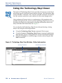
Analyzing Synthesis Results with the Technology Map Viewer ............................. 84
Performing Incremental Synthesis ............................................................................... 86
Chapter 5: Place & Route ............................................................................................................. 89
Introduction..................................................................................................................... 90
Performing a Full Incremental Compilation .............................................................. 92
Analyzing Fitting Results .............................................................................................. 93
Using the Messages Window to View Fitting Results ................................ 93
Using the Report Window or Report File to View Fitting Results ............ 95
Using the Timing Closure Floorplan to Analyze Results ........................... 96
Using the Design Assistant to Check Design Reliability............................ 98
Optimizing the Fit .......................................................................................................... 99
Using Location Assignments.......................................................................... 99
Setting Options that Control Place & Route............................................... 100
Setting Fitter Options ...................................................................... 100
Setting Physical Synthesis Optimization Options ...................... 101
Setting Individual Logic Options that Affect Fitting.................. 101
Using the Resource Optimization Advisor ................................................ 102
Using the Design Space Explorer................................................................. 105
Preserving Assignments through Back-Annotation................................................ 109
Chapter 6: Block-Based Design................................................................................................. 113
Introduction................................................................................................................... 114
Quartus II Block-Based Design Flow ......................................................................... 114
Using LogicLock Regions ............................................................................................ 116
Using LogicLock Regions in Top-Down Incremental Compilation Flows........... 119
Saving Intermediate Synthesis Results for Bottom-Up LogicLock Flows............ 120
Back-Annotating LogicLock Region Assignments.................................... 122
Exporting & Importing LogicLock Assignments ...................................... 122
Using LogicLock with EDA Tools .............................................................................. 124
IV
■
INTRODUCTION TO QUARTUS II
ALTERA CORPORATION
TABLE OF CONTENTS
Chapter 7: Simulation ................................................................................................................ 127
Introduction................................................................................................................... 128
Simulating Designs with EDA Tools ......................................................................... 129
Specifying EDA Simulation Tool Settings .................................................. 130
Generating Simulation Output Files ........................................................... 131
EDA Simulation Flow.................................................................................... 132
Functional Simulation Flow ........................................................... 132
NativeLink Simulation Flow.......................................................... 133
Manual Timing Simulation Flow .................................................. 133
Simulation Libraries ........................................................................ 134
Simulating Designs with the Quartus II Simulator ................................................. 136
Creating Waveform Files............................................................................... 138
Using the Simulator Tool .............................................................................. 139
Chapter 8: Timing Analysis....................................................................................................... 141
Introduction................................................................................................................... 142
Performing Timing Analysis in the Quartus II Software........................................ 143
Specifying Timing Requirements................................................................. 143
Specifying Project-Wide Timing Settings ..................................... 145
Specifying Individual Timing Assignments ................................ 146
Performing a Timing Analysis ..................................................................... 148
Performing an Early Timing Estimate....................................................................... 150
Viewing Timing Analysis Results .............................................................................. 152
Using the Report Window ............................................................................ 152
Making Assignments & Viewing Delay Paths........................................... 153
Using the Technology Map Viewer ............................................................. 156
Performing Timing Analysis by Using EDA Tools .................................................. 157
Using the PrimeTime Software .................................................................... 159
Using the Tau Software ................................................................................. 160
Chapter 9: Timing Closure ........................................................................................................ 161
Introduction................................................................................................................... 162
Using the Timing Closure Floorplan ......................................................................... 162
Viewing Assignments & Routing ................................................................ 163
Making Assignments..................................................................................... 165
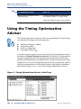
Using the Timing Optimization Advisor .................................................................. 166
Using Netlist Optimizations to Achieve Timing Closure....................................... 167
Using LogicLock Regions to Achieve Timing Closure ........................................... 169
Soft LogicLock Regions ................................................................................. 170
Path-Based Assignments............................................................................... 170
Using the Design Space Explorer to Achieve Timing Closure............................... 172
Using Incremental Compilation to Achieve Timing Closure................................. 172
Chapter 10: Power Analysis...................................................................................................... 173
Introduction................................................................................................................... 174
Performing Power Analysis with the PowerPlay Power Analyzer ...................... 174
ALTERA CORPORATION
INTRODUCTION TO QUARTUS II
■
V
TABLE OF CONTENTS
Specifying Power Analyzer Options ......................................................................... 176
Using the PowerPlay Early Power Estimator........................................................... 178
Chapter 11: Programming & Configuration ........................................................................... 181
Introduction................................................................................................................... 182
Programming One or More Devices by Using the Programmer ........................... 186
Creating Secondary Programming Files ................................................................... 187
Creating Other Programming File Formats ............................................... 188
Converting Programming Files.................................................................... 190
Using the Quartus II Software to Program Via a Remote JTAG Server................ 194
Chapter 12: Debugging .............................................................................................................. 195
Introduction................................................................................................................... 196
Using the SignalTap II Logic Analyzer...................................................................... 197
Setting Up & Running the SignalTap II Logic Analyzer .......................... 198
Using the SignalTap II Logic Analyzer with Incremental Compilation. 202
Analyzing SignalTap II Data......................................................................... 203
Using SignalProbe ........................................................................................................ 205
Using the In-System Memory Content Editor.......................................................... 208
Using the RTL Viewer & Technology Map Viewer.................................................. 210
Using the Chip Editor .................................................................................................. 211
Chapter 13: Engineering Change Management ..................................................................... 213
Introduction................................................................................................................... 214
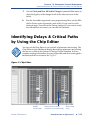
Identifying Delays & Critical Paths by Using the Chip Editor .............................. 215
Editing Atoms in the Chip Editor .............................................................................. 217
Modifying Resource Properties by Using the Resource Property Editor............. 217
Viewing & Managing Changes with the Change Manager.................................... 219
Verifying the Effect of ECO Changes......................................................................... 221
Chapter 14: Formal Verification................................................................................................ 223
Introduction................................................................................................................... 224
Using EDA Formal Verification Tools........................................................................ 225
Specifying Additional Settings ................................................................................... 227
Chapter 15: System-Level Design............................................................................................. 229
Introduction................................................................................................................... 230
Creating SOPC Designs with SOPC Builder ............................................................ 232
Creating the System ....................................................................................... 232
Generating the System................................................................................... 233
Creating DSP Designs with the DSP Builder............................................................ 234
Instantiating Functions.................................................................................. 235
Generating Simulation Files ......................................................................... 235
Generating Synthesis Files ............................................................................ 235
VI
■
INTRODUCTION TO QUARTUS II
ALTERA CORPORATION
TABLE OF CONTENTS
Chapter 16: Software Development ......................................................................................... 237
Introduction................................................................................................................... 238
Using the Software Builder in the Quartus II Software .......................................... 238
Specifying Software Build Settings ............................................................................ 239
Generating Software Output Files ............................................................................. 239
Generating Flash Programming Files ......................................................... 240
Generating Passive Programming Files...................................................... 242
Generating Memory Initialization Data Files ............................................ 244
Chapter 17: Installation, Licensing & Technical Support...................................................... 247
Installing the Quartus II Software.............................................................................. 248
Licensing the Quartus II Software ............................................................................. 249
Getting Technical Support........................................................................................... 251
Chapter 18: Documentation & Other Resources .................................................................... 253
Getting Online Help..................................................................................................... 254
Using the Quartus II Online Tutorial......................................................................... 255
Other Quartus II Software Documentation .............................................................. 256
Other Altera Literature ................................................................................................ 257
Index ............................................................................................................................................. 259
ALTERA CORPORATION
INTRODUCTION TO QUARTUS II
■
VII
Preface
The Altera® Quartus® II design software is the most comprehensive
environment available for system-on-a-programmable-chip (SOPC) design.
If you have primarily used the MAX+PLUS® II software, other design
software, or ASIC design software in the past, and are thinking of making
the switch to the Quartus II software, or if you are somewhat familiar with
the Quartus II software but would like to gain a greater knowledge of its
capabilities, this manual is for you.
This manual is designed for the novice Quartus II software user and
provides an overview of the capabilities of the Quartus II software in
programmable logic design. It is not, however, intended to be an exhaustive
reference manual for the Quartus II software. Instead, it is a guide that
explains the features of the software and how these can assist you in FPGA
and CPLD design. This manual is organized into a series of specific
programmable logic design tasks. Whether you use the Quartus II graphical
user interface, other EDA tools, or the Quartus II command-line interface,
this manual guides you through the features that are best suited to your
design flow.
The first chapter gives an overview of the major graphical user interface,
EDA tool, and command-line interface design flows. Each subsequent
chapter begins with an introduction to the specific purpose of the chapter,
and leads you through an overview of each task flow. It shows how to
integrate the Quartus II software with your existing EDA tool and
command-line design flows. In addition, the manual refers you to other
resources that are available to help you use the Quartus II software, such as
Quartus II online Help and the Quartus II online tutorial, application notes,
white papers, and other documents and resources that are available on the
Altera web site.
Follow this manual through a tour of the Quartus II software to learn how it
can help you increase productivity and shorten design cycles, integrate with
existing programmable logic design flows, and achieve design,
performance, and timing requirements quickly and efficiently.
ALTERA CORPORATION
INTRODUCTION TO QUARTUS II
■
IX
Documentation Conventions
The Introduction to Quartus® II manual uses the following conventions to
make it easy for you to find and interpret information.
Typographic Conventions
Quartus II documentation uses the typographic conventions shown in the
following table:
Visual Cue
Meaning
Bold Initial
Capitals
Command names; dialog box, page, and tab titles; and button names
are shown in bold, with initial capital letters. For example: Find Text
command, Save As dialog box, and Start button.
bold
Directory names, project names, disk drive names, file names, file
name extensions, software utility names, software executable
names, and options in dialog boxes are shown in bold. Examples:
quartus directory, d: drive, license.dat file.
Initial Capitals
Keyboard keys, user-editable application window fields, and menu
names are shown with initial capital letters. For example: Delete key,
the Options menu.
“Subheading
Title”
Subheadings within a manual section are enclosed in quotation
marks. In manuals, titles of Help topics are also shown in quotation
marks.
Italic Initial
Capitals
Help categories, manual titles, section titles in manuals, and
application note and brief names are shown in italics with initial
capital letters. For example: FLEXlm End Users Guide.
italics
Variables are enclosed in angle brackets (< >) and shown in italics.
For example: <file name>, <CD-ROM drive>.
Courier font
Anything that must be typed exactly as it appears is shown in
Courier. For example: \quartus\bin\lmulti lmhostid.
r
Enter or return key.
■
f
v
!
ALTERA CORPORATION
Bullets are used in a list of items when the sequence of the items is
not important.
The feet show you where to go for more information on a particular
topic.
The checkmark indicates a procedure that consists of one step only.
The hand points to information that requires special attention.
INTRODUCTION TO QUARTUS II
■
XI
DOCUMENTATION CONVENTIONS
Terminology
The following table shows terminology that is used throughout the
Introduction to Quartus II manual:
Term
Meaning
“click”
Indicates a quick press and release of the left mouse button.
“double-click”
Indicates two clicks in rapid succession.
“choose”
Indicates that you need to use a mouse or key combination to
start an action.
“select”
Indicates that you need to highlight text and/or objects or an
option in a dialog box with a key combination or the mouse. A
selection does not start an action. For example: Select Chain
Description File, and click OK.
“turn on”/“turn off”
Indicates that you must click a check box to turn a function on
or off.
XII
■
INTRODUCTION TO QUARTUS II
ALTERA CORPORATION
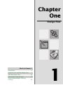
Chapter
One
Design Flow
What’s in Chapter 1:
Introduction
Graphical User Interface Design Flow
2
3
EDA Tool Design Flow
10
Command-Line Design Flow
16
Design Methodologies & Design
Planning
30
1
CHAPTER 1: DESIGN FLOW
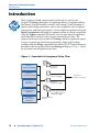
INTRODUCTION
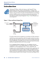
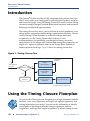
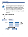
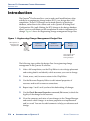
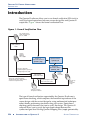
Introduction
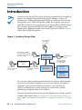
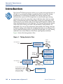
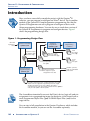
The Altera® Quartus® II design software provides a complete, multiplatform
design environment that easily adapts to your specific design needs. It is a
comprehensive environment for system-on-a-programmable-chip (SOPC)
design. The Quartus II software includes solutions for all phases of FPGA
and CPLD design. See Figure 1 for an illustration of the Quartus II design
flow.
Figure 1. Quartus II Design Flow
Design Entry
Includes block-based design,
system-level design &
software development
Synthesis
Power
Analysis
Place & Route
Debugging
Timing
Analysis
Engineering
Change
Management
Simulation
Timing
Closure
Programming &
Configuration
In addition, the Quartus II software allows you to use the Quartus II
graphical user interface, EDA tool interface, or command-line interface for
each phase of the design flow. You can use one of these interfaces for the
entire flow, or you can use different options at different phases of the design
flow. This chapter explains the options that are available for each of the
design flows, as well as design methodologies. The remaining chapters in
this manual describe individual stages of the design flow in more detail.
2
■
INTRODUCTION TO QUARTUS II
ALTERA CORPORATION
CHAPTER 1: DESIGN FLOW
GRAPHICAL USER INTERFACE DESIGN FLOW
Graphical User Interface Design
Flow
You can use the Quartus II software to perform all stages of the design flow;
it is a complete, easy-to-use, stand-alone solution. Figure 2 shows the
features that the Quartus II graphical user interface provides for each stage
of the design flow.
Figure 2. Quartus II Graphical User Interface Features
Design Entry
● Text Editor
● Block & Symbol Editor
● MegaWizard Plug-In Manager
System-Level Design
● SOPC Builder
● DSP Builder
Constraint Entry
● Assignment Editor
● Pin Planner
● Settings Dialog Box
● Floorplan Editor
● Design Partitions Window
Software Development
● Software Builder
Synthesis
● Analysis & Synthesis
● VHDL, Verilog HDL & AHDL
● Design Assistant
● RTL Viewer
● Technology Map Viewer
● Incremental Synthesis
Place & Route
● Fitter
● Assignment Editor
● Floorplan Editor
● Incremental Compilation
● Report Window
● Resource Optimization Advisor
● Design Space Explorer
● Chip Editor
Timing Analysis
● Timing Analyzer
● Report Window
● Technology Map Viewer
Simulation
● Simulator
● Waveform Editor
Programming
● Assembler
● Programmer
● Convert Programming Files
ALTERA CORPORATION
Block-Based Design
● LogicLock Window
● Floorplan Editor
● VQM Writer
EDA Interface
● EDA Netlist Writer
Power Analysis
● PowerPlay Power Analyzer Tool
● PowerPlay Early Power Estimator
Timing Closure
● Floorplan Editor
● LogicLock Window
● Timing Optimization Advisor
● Design Space Explorer
● Incremental Compilation
Debugging
● SignalTap II
● SignalProbe
● In-System Memory Content Editor
● RTL Viewer
● Technology Map Viewer
● Chip Editor
Engineering Change
Management
● Chip Editor
● Resource Property Editor
● Change Manager
INTRODUCTION TO QUARTUS II
■
3
CHAPTER 1: DESIGN FLOW
GRAPHICAL USER INTERFACE DESIGN FLOW
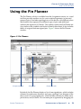
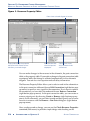
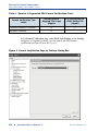
Figure 3 shows the Quartus II graphical user interface as it appears when
you first start the software.
Figure 3. Quartus II Graphical User Interface
The Quartus II software includes a modular Compiler. The Compiler
includes the following modules (modules marked with an asterisk are
optional during a full compilation, depending on your settings):
■
■
■
■
■
■
■
■
4
■
Analysis & Synthesis
Partition Merge*
Fitter
Assembler*
Timing Analyzer*
Design Assistant*
EDA Netlist Writer*
HardCopy® Netlist Writer*
INTRODUCTION TO QUARTUS II
ALTERA CORPORATION
CHAPTER 1: DESIGN FLOW
GRAPHICAL USER INTERFACE DESIGN FLOW
You can run all Compiler modules as part of a full compilation by choosing
Start Compilation (Processing menu). You can also run each module
individually by choosing Start (Processing menu) and then choosing the
command for the module you want to start from the Start submenu. You can
also run some of the Compiler modules incrementally. See “Top-Down
Incremental Compilation Flow” on page 30 for more information.
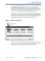
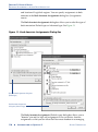
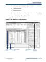
In addition, you can start the Compiler modules by choosing Compiler Tool
(Tools menu) and running the module in the Compiler Tool window. The
Compiler Tool window also allows you to open the settings file or report file
for the module, or to open other related windows. See Figure 4.
Figure 4. Compiler Tool Window
Start module
Open module settings page
Open report file
The Quartus II software also provides some predefined compilation flows,
which you can use with commands from the Processing menu. Table 1 lists
the commands for some of the most common compilation flows.
ALTERA CORPORATION
INTRODUCTION TO QUARTUS II
■
5
CHAPTER 1: DESIGN FLOW
GRAPHICAL USER INTERFACE DESIGN FLOW
Table 1. Commands for Common Compiler Flows
Flow
Description
Quartus II Command
from Processing Menu
Full compilation
flow
Performs a full compilation of the
current design.
Start Compilation
command
Compilation and
simulation flow
If the simulation mode is timing, flow
performs a full compilation and then a
simulation of the current design. If the
simulation mode is functional, the flow
performs only the Generate
Functional Simulation Netlist
command and then a simulation of the
current design.
Start Compilation and
Simulation command
SignalProbe™
flow
Routes user-specified signals to output
pins without affecting the existing
fitting in a design, so that you can debug
signals without completing a full
compilation.
Start > Start
SignalProbe
Compilation command
Early Timing
Estimate
Performs a partial compilation, but stops
and generates early timing estimates
before the Fitter is complete.
Start > Start Early
Timing Estimate
command
Partition Merge
f
Merges the design partitions after
incremental synthesis to create a
flattened netlist for use in further stages
of compilation. You must run this
command if you are using incremental
synthesis and do not fully recompile the
design after you make design changes.
Start > Start Partition
Merge command
For Information About
Refer To
Using compilation flows
“Overview: Using Compilation Flows” in
Quartus II Help
You can customize the layout, menus, commands, and icons in the
Quartus II software according to your individual preferences. You can
choose between the standard Quartus II user interface or the MAX+PLUS® II
look and feel when starting the Quartus II software for the first time, or you
can choose the look and feel later by using the Customize dialog box (Tools
menu). If you have previously used the MAX+PLUS II software, the
6
■
INTRODUCTION TO QUARTUS II
ALTERA CORPORATION
CHAPTER 1: DESIGN FLOW
GRAPHICAL USER INTERFACE DESIGN FLOW
MAX+PLUS II look and feel allows you to use the familiar MAX+PLUS II
layout, commands, and icons to control functions of the Quartus II software.
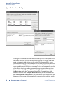
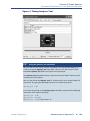
Figure 5 shows the Customize dialog box.
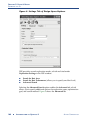
Figure 5. Customize Dialog Box
The Customize dialog box also allows you to choose whether you want the
optional Quartus II or the MAX+PLUS II quick menus to display, and
whether you want them on the right or left side of the menu bar. The
Quartus II quick menu contains menu commands for each Quartus II
application and common processing commands. The MAX+PLUS II quick
menu, which is similar to the MAX+PLUS II menu from the MAX+PLUS II
software, provides commands for applications and common MAX+PLUS II
menu commands. The commands on the MAX+PLUS II menu perform the
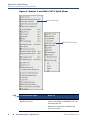
same functions as the corresponding Quartus II commands. Figure 6 shows
the Quartus II and MAX+PLUS II quick menus.
ALTERA CORPORATION
INTRODUCTION TO QUARTUS II
■
7
CHAPTER 1: DESIGN FLOW
GRAPHICAL USER INTERFACE DESIGN FLOW
Figure 6. Quartus II and MAX+PLUS II Quick Menus
Quartus II Quick Menu
MAX+PLUS II Quick Menu
f
For Information About
Refer To
Using the Quartus II design flow for
MAX+PLUS II users
“Quartus II Design Flow for MAX+PLUS II
Users” in the Quartus II Handbook, vol. 1 on
the Altera web site
MAX+PLUS II Conversion module of the
Quartus II Tutorial
8
■
INTRODUCTION TO QUARTUS II
ALTERA CORPORATION
CHAPTER 1: DESIGN FLOW
GRAPHICAL USER INTERFACE DESIGN FLOW
f
For Information About
Refer To
Customizing the user interface
“Overview: Working With the User Interface”
and “Customizing the User Interface” in
Quartus II Help
Using the MAX+PLUS II look and feel
“MAX+PLUS II Quick Start Guide for the
Quartus II Software” and “List of
MAX+PLUS II Commands” in Quartus II Help
The following steps describe the basic design flow for using the Quartus II
graphical user interface:
1.
Create a new project and specify a target device or device family by
using the New Project Wizard (File menu).
2.
Create a Verilog HDL, VHDL, or Altera Hardware Description
Language (AHDL) design by using the Text Editor. If you want, you
can use the Block Editor to create a block diagram with symbols that
represent other design files, or to create a schematic. You can also use
the MegaWizard® Plug-In Manager (Tools menu) to generate custom
variations of megafunctions and IP functions to instantiate in your
design.
3.
(Optional) Specify initial design constraints using the Assignment
Editor, the Pin Planner, the Settings dialog box (Assignments menu),
the Floorplan Editor, the Design Partitions window, and/or the
LogicLock™ feature.
4.
(Optional) Perform an Early Timing Estimate to generate early
estimates of timing results before the Fitter is complete.
5.
(Optional) Create a system-level design by using the SOPC Builder or
DSP Builder.
6.
(Optional) Create software and programming files for Excalibur™
device processors or Nios® II embedded processors by using the
Software Builder.
7.
Synthesize the design by using Analysis & Synthesis.
8.
(Optional) If your design contains partitions and you are not
performing a full compilation, merge the partitions with Partition
Merge.
ALTERA CORPORATION
INTRODUCTION TO QUARTUS II
■
9
CHAPTER 1: DESIGN FLOW
EDA TOOL DESIGN FLOW
9.
(Optional) Perform functional simulation on the design by using the
Simulator and the Generate Functional Simulation Netlist command.
10. Perform place and route on the design by using the Fitter.
11. Perform a power estimation and analysis by using the PowerPlay
Power Analyzer.
12. Perform timing analysis on the design by using the Timing Analyzer.
13. Perform timing simulation on the design by using the Simulator.
14. (Optional) Make timing improvements to achieve timing closure by
using physical synthesis, the Timing Closure floorplan, the LogicLock
feature, the Settings dialog box, and the Assignment Editor.
15. Create programming files for your design by using the Assembler.
16. Program the device by using programming files, the Programmer, and
Altera hardware; or convert programming files to other file formats for
use by other systems, such as embedded processors.
17. (Optional) Debug the design by using the SignalTap® II Logic Analyzer,
the SignalProbe™ feature, or the Chip Editor.
18. (Optional) Manage engineering changes by using the Chip Editor, the
Resource Property Editor, and the Change Manager.
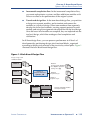
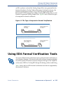
EDA Tool Design Flow
The Quartus II software allows you to use the EDA tools you are familiar
with for various stages of the design flow. You can use these tools together
with the Quartus II graphical user interface or with Quartus II commandline executables. Figure 7 shows the EDA tool design flow.
10
■
INTRODUCTION TO QUARTUS II
ALTERA CORPORATION
CHAPTER 1: DESIGN FLOW
EDA TOOL DESIGN FLOW
Figure 7. EDA Tool Design Flow
Source design files,
including VHDL Design
Files (.vhd) & Verilog
Design Files (.v)
Quartus II
Analysis &
Synthesis
EDA Synthesis
Tool
EDA Physical
Synthesis Tool
Quartus II Fitter
EDIF netlist
files (.edf) or Verilog
Quartus Mapping Files (.vqm)
Quartus II
Timing Analyzer
EDA Timing
Analysis Tool
EDA Formal
Verification Tool
Quartus II
EDA Netlist Writer
EDA Simulation
Tool
Quartus II
Simulator
Quartus II
Assembler
EDA Board-Level
Design Tool
Output files for EDA tools,
including Verilog Output Files (.vo),
VHDL Output Files (.vho), VQM
Files, Standard Delay Format
Output Files (.sdo), testbench files,
symbol files, Tcl script files (.tcl),
IBIS Output Files (.ibs) & STAMP
model files (.data, or .mod)
Quartus II
Programmer
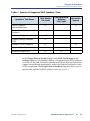
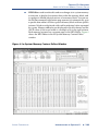
Table 2 shows the EDA tools that are supported by the Quartus II software,
and indicates which EDA tools have NativeLink® support. NativeLink
technology facilitates the seamless transfer of information between the
Quartus II software and other EDA tools and allows you to run the EDA tool
automatically from within the Quartus II software.
ALTERA CORPORATION
INTRODUCTION TO QUARTUS II
■
11
CHAPTER 1: DESIGN FLOW
EDA TOOL DESIGN FLOW
Table 2. EDA Tools Supported by the Quartus II Software (Part 1 of 2)
Function
Design Entry &
Synthesis
Supported EDA Tools
NativeLink
Support
Mentor Graphics Design Architect
Mentor Graphics LeonardoSpectrum
v
Mentor Graphics Precision RTL Synthesis
v
Mentor Graphics ViewDraw
Synopsys Design Compiler
Synopsys Design Compiler FPGA
Simulation
Synopsys FPGA Compiler II
v
Synplicity Synplify
v
Synplicity Synplify Pro
v
Cadence NC-Verilog
v
Cadence NC-VHDL
v
Cadence Verilog-XL
Mentor Graphics® ModelSim®
v
Mentor Graphics ModelSim-Altera
v
Synopsys VCS MX
v
Synopsys VCS
v
Synopsys VSS
Timing Analysis
Mentor Graphics Tau (through Stamp)
Synopsys PrimeTime
Board-Level Design
v
Hyperlynx (through Signal Integrity IBIS)
XTK (through Signal Integrity IBIS)
ICX (through Signal Integrity IBIS)
SpectraQuest (through Signal Integrity IBIS)
Mentor Graphics Symbol Generation
(Viewdraw)
Formal Verification
Cadence Encounter Conformal
Synopsys Formality
12
■
INTRODUCTION TO QUARTUS II
ALTERA CORPORATION
CHAPTER 1: DESIGN FLOW
EDA TOOL DESIGN FLOW
Table 2. EDA Tools Supported by the Quartus II Software (Part 2 of 2)
Function
Physical Synthesis
Supported EDA Tools
NativeLink
Support
Magma Design Automation PALACE
v
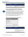
Synplicity Amplify
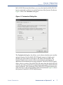
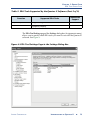
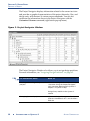
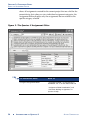
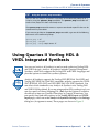
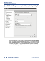
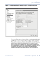
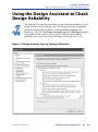
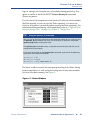
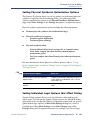
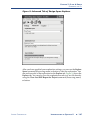
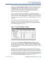
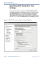
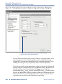
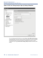
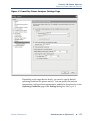
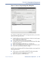
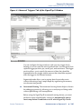
The EDA Tool Settings page of the Settings dialog box (Assignments menu)
allows you to specify which EDA tools you want to use with the Quartus II
software. See Figure 8.
Figure 8. EDA Tool Settings Page in the Settings Dialog Box
ALTERA CORPORATION
INTRODUCTION TO QUARTUS II
■
13
CHAPTER 1: DESIGN FLOW
EDA TOOL DESIGN FLOW
The individual pages under EDA Tool Settings provide additional options
for each type of EDA tool.
The following steps describe the basic design flow for using other EDA tools
with the Quartus II software. Refer to Table 2 on page 12 for a list of the
supported EDA tools.
14
■
1.
Create a new project and specify a target device or device family.
2.
Create a Verilog HDL or VHDL design file by using a standard text
editor. If you want, instantiate functions from libraries, or use the
MegaWizard Plug-In Manager (Tools menu) to create custom
variations of megafunctions.
3.
Synthesize your design by using one of the Quartus II–supported EDA
synthesis tools, and generate an EDIF netlist file (.edf) or a Verilog
Quartus Mapping File (.vqm).
4.
(Optional) Perform functional simulation on your design by using one
of the Quartus II–supported simulation tools.
5.
In the Quartus II Settings dialog box (Assignments menu), specify
which EDA design entry, synthesis, simulation, timing analysis, boardlevel verification, formal verification, and physical synthesis tools you
are using with the Quartus II software, and specify additional options
for those tools.
6.
Compile your design and perform place and route by using the
Quartus II software. You can perform a full compilation, or you can run
the Compiler modules individually:
a.
Run Analysis & Synthesis to process your design and map the
functions in your design to the correct library module.
b.
Run the Fitter to place and route your design.
c.
Run the Timing Analyzer to perform timing analysis on your
design.
d.
Run the EDA Netlist Writer to generate output files for use with
other EDA tools.
e.
Run the Assembler to create programming files for your design.
INTRODUCTION TO QUARTUS II
ALTERA CORPORATION
CHAPTER 1: DESIGN FLOW
EDA TOOL DESIGN FLOW
7.
(Optional) Perform timing analysis on your design by using one of the
Quartus II–supported EDA timing analysis tools.
8.
(Optional) Perform timing simulation on your design by using one of
the Quartus II–supported EDA simulation tools.
9.
(Optional) Perform board-level verification by using one of the
Quartus II–supported EDA board-level verification tools.
10. (Optional) Perform formal verification by using one of the Quartus II–
supported EDA formal verification tools to make sure that Quartus
post-fit netlist is equivalent to that of the synthesized netlist.
11. (Optional) Perform physical synthesis by using one of the Quartus II–
supported EDA physical synthesis tools.
Program the device by using programming files, the Programmer, and
Altera hardware; or convert programming files to other file formats for use
by other systems, such as embedded processors.
f
For Information About
Refer To
Using the Quartus II software with
Synplicity Synplify and Synplify Pro
software
“Synplicity Synplify and Synplify Pro
Support” in the Quartus II Handbook, vol. 1
on the Altera web site
Using the Quartus II software with
Mentor Graphics LeonardoSpectrum
software
“Mentor Graphics LeonardoSpectrum
Support” in the Quartus II Handbook, vol. 1
on the Altera web site
Using the Quartus II software with
Mentor Graphics Precision RTL
Synthesis software
“Mentor Graphics Precision RTL Synthesis
Support” in the Quartus II Handbook, vol. 1,
on the Altera web site
Using the Quartus II software with
Synopsis DC FPGA software
“Synopsys Design Compiler FPGA Support”
in the Quartus II Handbook, vol. 1, on the
Altera web site
Using the Quartus II software with
Synplicity Amplify software
“Synplicity Amplify Physical Synthesis
Support” in the Quartus II Handbook, vol. 2,
on the Altera web site
Using the Quartus II software with
Mentor Graphics ModelSim software
“Mentor Graphics ModelSim Support” in the
Quartus II Handbook, vol. 3, on the Altera
web site
Using the Quartus II software with
Synopsys VCS software
“Synopsys VCS Support” in the Quartus II
Handbook, vol. 3, on the Altera web site
Using the Quartus II software with
Cadence NC-Sim software
“Cadence NC-Sim Support” in the Quartus II
Handbook, vol. 3, on the Altera web site
ALTERA CORPORATION
INTRODUCTION TO QUARTUS II
■
15
CHAPTER 1: DESIGN FLOW
COMMAND-LINE DESIGN FLOW
f
For Information About
Refer To
Using the Quartus II software with
Synopsis PrimeTime software
“Synopsys PrimeTime Support” in the
Quartus II Handbook, vol. 3, on the Altera
web site
Using the Quartus II software with
Cadence Encounter Conformal
software
“Cadence Encounter Conformal
Equivalency Checker Support” in the
Quartus II Handbook, vol. 3, on the Altera
web site
Using the Quartus II software with
Synopsys Formality software
“Synopsys Formality Support” in the
Quartus II Handbook, vol. 3, on the Altera
web site
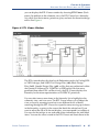
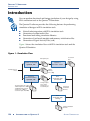
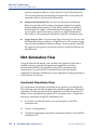
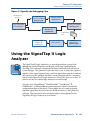
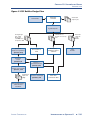
Command-Line Design Flow
The Quartus II software offers a complete command-line interface solution.
It allows you to perform every stage of the design flow by using commandline executables and options. Using the command-line flow allows you to
reduce memory requirements; control the Quartus II software with scripts or
standard command-line options and commands, including Tcl commands;
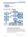
and create makefiles. See Figure 9 for an illustration of the command-line
design flow.
16
■
INTRODUCTION TO QUARTUS II
ALTERA CORPORATION
CHAPTER 1: DESIGN FLOW
COMMAND-LINE DESIGN FLOW
Figure 9. Command-Line Design Flow
Quartus II Shell
quartus_sh
The Quartus II Shell can be
used as a Tcl interpreter for
the Quartus II executables
Source design files, including Verilog Design Files
(.v), VHDL Design Files (.vhd), Verilog Quartus
Mapping Files (.vqm), Text Design Files (.tdf), Block
Design Files (.bdf) & EDIF netlist files (.edf)
Analysis &
Synthesis
quartus_map
Design Assistant
quartus_drc
Simulator
quartus_sim
Fitter
quartus_fit
Timing Analyzer
quartus_tan
Compiler Database
quartus_cdb
PowerPlay Power
Analyzer
quartus_pow
Assembler
quartus_asm
EDA Netlist Writer
quartus_eda
Software Builder
quartus_swb
Output files for EDA tools,
including Verilog Output
Files (.vo), VHDL Output
Files (.vho), VQM Files &
Standard Delay Format
Output Files (.sdo)
Programmer
quartus_pgm
Convert
Programming Files
quartus_cpf
SignalTap II Logic
Analyzer
quartus_stp
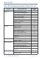
Command-Line Executables
The Quartus II software includes separate executables for each stage of the
design flow. Each executable occupies memory only while it is being run.
You can use these executables with standard command-line commands and
scripts, with Tcl scripts, and in makefile scripts. See Table 3 for a list of all of
the available command-line executables.
ALTERA CORPORATION
INTRODUCTION TO QUARTUS II
■
17
CHAPTER 1: DESIGN FLOW
COMMAND-LINE DESIGN FLOW
[
!
Stand-Alone Graphical User Interface Executables
The Quartus II software also provides some stand-alone graphical user interface
(GUI) executables. The qmegawiz executable provides a stand-alone GUI version of
the MegaWizard Plug-In Manager, the quartus_pgmw executable provides a
stand-alone GUI for the Programmer, and the quartus_stpw executable provides a
stand-alone GUI for the SignalTap II Logic Analyzer.
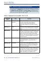
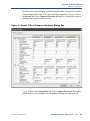
Table 3. Command-Line Executables (Part 1 of 2)
Executable
Name
Title
Function
quartus_map
Analysis &
Synthesis
Creates a project if one does not already exist,
and then creates the project database,
synthesizes your design, and performs
technology mapping on the project’s design
files.
quartus_fit
Fitter
Places and routes a design. Analysis & Synthesis
must be run successfully before running the
Fitter.
quartus_drc
Design Assistant
Checks the reliability of a design based on a set
of design rules. Design Assistant is especially
useful for checking the reliability of a design
before converting the design for HardCopy
devices. Either Analysis & Synthesis or the Fitter
must be run successfully before running the
Design Assistant.
quartus_tan
Timing Analyzer
Analyzes the speed performance of the
implemented circuit. The Fitter must be run
successfully before running the Timing
Analyzer.
quartus_asm
Assembler
Creates one or more programming files for
programming or configuring the target device.
The Fitter must be run successfully before
running the Assembler.
quartus_eda
EDA Netlist Writer
Generates netlist files and other output files for
use with other EDA tools. Analysis & Synthesis,
the Fitter, or the Timing Analyzer must be run
successfully before running the EDA Netlist
Writer, depending on the options used.
18
■
INTRODUCTION TO QUARTUS II
ALTERA CORPORATION
CHAPTER 1: DESIGN FLOW
COMMAND-LINE DESIGN FLOW
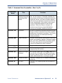
Table 3. Command-Line Executables (Part 2 of 2)
Executable
Name
Title
Function
quartus_cdb
Compiler
Database Interface
(including VQM
Writer)
Generates internal netlist files, including VQM
Files, for the Quartus II Compiler database so
they can be used for back-annotation and for the
LogicLock feature, and back-annotates device
and resource assignments to preserve the fit for
future compilations. Also imports and exports
version-compatible databases and merges
partitions. Either the Fitter or Analysis &
Synthesis must be run successfully before
running the Compiler Database Interface.
quartus_sim
Simulator
Performs functional or timing simulation on your
design. Analysis & Synthesis must be run before
performing a functional simulation. The Timing
Analyzer must be run before performing a
timing simulation.
quartus_pow
Power Analyzer
Analyzes and estimates total dynamic and static
power consumed by a design. Computes toggle
rates and static probabilities for output signals.
The Fitter must be run successfully before
running the PowerPlay Power Analyzer.
quartus_pgm
Programmer
Programs Altera devices.
quartus_cpf
Convert
Programming Files
Converts programming files to secondary
programming file formats.
quartus_stp
SignalTap II Logic
Analyzer
Sets up your SignalTap II File (.stp). When it is
run after the Assembler, the SignalTap II Logic
Analyzer captures signals from internal device
nodes while the device is running at speed.
quartus_swb
Software Builder
Processes a design for an Excalibur embedded
processor.
quartus_sh
Tcl Shell
Provides a Tcl scripting shell for the Quartus II
software.
ALTERA CORPORATION
INTRODUCTION TO QUARTUS II
■
19
CHAPTER 1: DESIGN FLOW
COMMAND-LINE DESIGN FLOW
!
Getting Help On the Quartus II Executables
If you want to get help on the command-line options that are available for each of
the Quartus II executables, type one of the following commands at the command
prompt:
<executable name> -h r
<executable name> --help r
<executable name> --help=<topic or option name>
r
You can also get help on command-line executables by using the Quartus II
Command-Line Executable and Tcl API Help Browser, which is a Tcl- and Tk-based
GUI that lets you browse the command-line and Tcl API help. To use this help, type
the following command at the command prompt:
quartus_sh --qhelp
r
You can run each executable individually, but you can also run all the
Compiler executables at once by using the following command:
quartus_sh --flow compile <project name> [-c <revision name>] r
This command will run the quartus_map, quartus_fit, quartus_asm, and
quartus_tan executables as part of a full compilation. Depending on your
settings, it may also run the optional quartus_drc, quartus_eda, and
quartus_cdb executables.
!
The quartus_cmd Executable
If you have used the quartus_cmd executable to perform project compilation in
previous versions of the Quartus II software, this executable is still supported for
backward compatibility; however, Altera recommends that for all new designs, you
do not use the quartus_cmd executable, but use the executables that are listed in
Table 3 on page 18. If you are used to using the quartus_cmd executable to
compile a design, you can get the same functionality by using the quartus_sh
executable with the following options:
quartus_sh --flow compile <project name> [-c < Revision Name> ]r
Some of the executables create a separate text-based report file that you can
view with any text editor. The name of each report file uses the following
format:
<revision name>.<abbreviated executable name>.rpt
20
■
INTRODUCTION TO QUARTUS II
ALTERA CORPORATION
CHAPTER 1: DESIGN FLOW
COMMAND-LINE DESIGN FLOW
For example, if you want to run the quartus_map executable for the chiptrip
project, you could type the following command at the command prompt:
quartus_map chiptrip r
The quartus_map executable will perform analysis and synthesis and will
produce a report file with the name chiptrip.map.rpt.
!
Using Quartus II Settings Files with Quartus II Executables
When you are using the Quartus II executables, the Quartus II software uses the
revision that has the same name as the project name, by default. If you want to use
a revision with a name that is different from the project name, you can use the -c
option to specify the name of the revision and its associated Quartus II Settings
File (.qsf). For example, if you want to run the quartus_map executable for the
chiptrip project with a revision named speed_ch and its associated speed_ch.qsf
file, you could type the following command at the command prompt:
quartus_map chiptrip -c speed_ch
r
The quartus_map executable performs analysis and synthesis using that revision
and settings, and produces a report file with the name speed_ch.map.rpt.
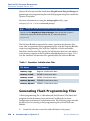
The Quartus II software also offers several predefined compilation flows
that use the Quartus II executables. You can use these commands with the
quartus_sh --flow command, or with the Tcl execute_flow
command. Table 4 shows some of the most common Compiler flows.
Table 4. Command-Line Compiler Flows (Part 1 of 2)
Command-Line Option for
quartus_sh --flow or
execute_flow
Flow
Description
Full compilation
flow
Performs a full compilation of the
current design.
compile
Compilation and
simulation flow
If the simulation mode is timing,
performs a full compilation and
then a simulation of the current
design. If the simulation mode is
functional, generates a functional
simulation netlist and then
performs a simulation of the
current design.
compile_and_simulate
ALTERA CORPORATION
INTRODUCTION TO QUARTUS II
■
21
CHAPTER 1: DESIGN FLOW
COMMAND-LINE DESIGN FLOW
Table 4. Command-Line Compiler Flows (Part 2 of 2)
Command-Line Option for
quartus_sh --flow or
execute_flow
Flow
Description
Attempt Similar
Placement flow
Performs a full compilation on a
previously compiled design
where the Fitter compares the
netlist and placement from the
previous and current
compilations. The Fitter compares
the compilations in order to use
as many node placements from
the previous compilation as
possible in the current
compilation.
attempt_similar_placement
SignalProbe flow
Routes user-specified signals to
output pins without affecting the
existing fitting in a design, so that
you can debug signals without
completing a full compilation.
signalprobe
Early Timing
Estimate
Performs a partial compilation,
but stops and generates early
timing estimates before the Fitter
is complete.
early_timing_estimate
Partition Merge
f
22
■
Merges the design partitions after
incremental synthesis to create a
flattened netlist for use in further
stages of compilation.You must run
this command if you are using
incremental synthesis and do not
fully recompile the design after you
make design changes.
merge
For Information About
Refer To
Using compilation flows
“Overview: Using Compilation Flows” in
Quartus II Help
INTRODUCTION TO QUARTUS II
ALTERA CORPORATION
CHAPTER 1: DESIGN FLOW
COMMAND-LINE DESIGN FLOW
Using Standard Command-Line
Commands & Scripts
You can use the Quartus II executables with any command-line scripting
method, such as Perl scripts, batch files, and Tcl scripts. These scripts can be
designed to create new projects or to compile existing projects. You can also
run the executables from the command prompt or console.
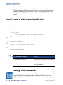
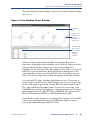
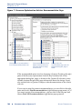
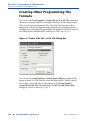
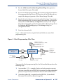
Figure 10 shows an example of a standard command-line script. The
example demonstrates how to create a project, perform analysis and
synthesis, perform place and route, perform timing analysis, and generate
programming files for the filtref tutorial design that is included with the
Quartus II software. If you have installed the tutorial design, it is in the
/altera/qdesigns<version number>/tutorial directory. Altera recommends
that you create a new directory and copy all the design files (*.v, *.bsf, *.bdf)
from the /altera/qdesigns<version number>/tutorial directory to the new
directory, in order to compile the design flow example. You can run the four
commands in Figure 10 from a command prompt in the new project
directory, or you can store them in a batch file or shell script. These examples
assume that the /<Quartus II system directory>/bin directory (or the
/<Quartus II system directory>/<platform> directory on UNIX or Linux
workstations, where <platform> can be solaris, linux, or hp_II) is included
in your PATH environment variable.
Figure 10. Example of a Command-Line Script
quartus_map filtref --family=Stratix
Creates a new
Quartus II project
targeting the Stratix
device family
quartus_fit filtref --part=EP1S10F780C5 --fmax=80MHz --tsu=8ns
Performs fitting for
the EP1S10F780C5
device and specifies
global timing
requirements
quartus_tan filtref
Performs timing
analysis
quartus_asm filtref
Generates
programming files
ALTERA CORPORATION
INTRODUCTION TO QUARTUS II
■
23
CHAPTER 1: DESIGN FLOW
COMMAND-LINE DESIGN FLOW
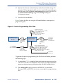
Figure 11 shows an excerpt from a sample command-line script for use on a
UNIX workstation. The script assumes that the Quartus II tutorial project
called fir_filter exists in the current directory. The script analyzes every
design file in the fir_filter project and reports any files that contain syntax
errors.
Figure 11. Example of a UNIX Command-Line Shell Script
#!/bin/sh
FILES_WITH_ERRORS=""
for filename in `ls *.bdf *.v`
do
quartus_map fir_filter --analyze_file=$filename
if [ $? -ne 0 ]
then
FILES_WITH_ERRORS="$FILES_WITH_ERRORS $filename"
fi
done
if [ -z "$FILES_WITH_ERRORS" ]
then
echo "All files passed the syntax check"
exit 0
else
echo "There were syntax errors in the following file(s)"
echo $FILES_WITH_ERRORS
exit 1
fi
f
For Information About
Refer To
Command-Line Scripting
“Command-Line Scripting” in the Quartus II
Handbook, vol. 2 on the Altera web site
Quartus II Scripting Reference Manual on
the Altera web site
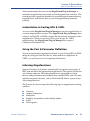
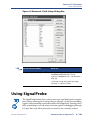
Using Tcl Commands
In the Quartus II software, you can run Tcl commands or create and run Tcl
scripts with the Quartus II executables to do the following tasks in a
Quartus II project. The Tcl API functions include the following categories:
24
■
INTRODUCTION TO QUARTUS II
ALTERA CORPORATION
CHAPTER 1: DESIGN FLOW
COMMAND-LINE DESIGN FLOW
■
■
■
■
■
■
■
■
■
■
■
■
■
Project & assignment functions
Device functions
Advanced device functions
Flow functions
Timing functions
Advanced timing functions
Simulator functions
Report functions
Timing report functions
Back-annotate functions
LogicLock functions
Chip Editor functions
Miscellaneous functions
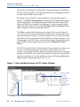
There are several ways to use Tcl scripts in the Quartus II software. You can
create a Tcl script by using commands from the Quartus II API for Tcl. You
should save a Tcl script as a Tcl Script File (.tcl).
The Templates command (Edit menu) in the Quartus II Text Editor allows
you to insert Tcl templates and Quartus II Tcl templates (for Quartus II
commands) into a text file to create Tcl scripts. Commands used in the
Quartus II Tcl templates use the same syntax as the Tcl API commands. If
you want to use an existing project as a baseline for another project, the
Generate Tcl File for Project command (Project menu) can generate a Tcl
Script File for the project.
You can run Tcl scripts in command-line mode with the quartus_sh
executable, in the Quartus II Tcl Console window, or from the Tcl Scripts
dialog box (Tools menu).
!
Getting Help On Tcl Commands
The Quartus II software includes a Quartus II Command-Line and Tcl API Help
browser, which is a Tcl- and Tk-based GUI that lets you browse the command-line
and Tcl API help. To use this help, type the following command at the command
prompt:
quartus_sh --qhelp
r
You can also view TCL API Help in the Quartus II Help that is available in the
graphical user interface. Refer to “Overview: Using Tcl Scripting” and “API Functions
for Tcl” in Quartus II Help for more information.
ALTERA CORPORATION
INTRODUCTION TO QUARTUS II
■
25
CHAPTER 1: DESIGN FLOW
COMMAND-LINE DESIGN FLOW
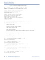
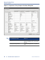
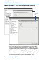
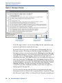
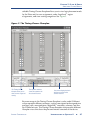
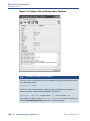
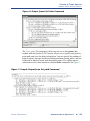
Figure 12 shows an example of a Tcl script.
Figure 12. Example of a Tcl Script (Part 1 of 2)
# Since ::quartus::report is not pre-loaded
# by quartus_sh, load this package now
# before using the report Tcl API
load_package report
# Since ::quartus::flow is not pre-loaded
# by quartus_sh, load this package now
# before using the flow Tcl API
# Type "help -pkg flow" to view information
# about the package
load_package flow
#------ Get Actual Fmax data from the Report File ------#
proc get_fmax_from_report {} {
#-------------------------------------------------------#
global project_name
# Load the project report database
load_report $project_name
# Get the actual Fmax
set actual_fmax [get_timing_analysis_summary_results -clock_setup
clock -actual]
# Now unload the project report database
unload_report
return $actual_fmax
}
#------ Set the project name to chiptrip ------#
set project_name chiptrip
#------ Create or open project ------#
if {project_exists $project_name} {
#------ Project already exists -- open project -------#
project_open $project_name
} else {
#------ Project does not exist -- create new project ------#
project_new $project_name
}
#------ Fmax requirement: 155.55MHz ------#
set required_fmax 155.55MHz
26
■
INTRODUCTION TO QUARTUS II
ALTERA CORPORATION
CHAPTER 1: DESIGN FLOW
COMMAND-LINE DESIGN FLOW
Figure 12. Example of a Tcl Script (Part 2 of 2)
#------ Make a clock assignment with the Fmax requirement ------#
create_base_clock clock -fmax $required_fmax
#------ Make global assignments ------#
set_global_assignment -name family STRATIX
set_global_assignment -name device EP1S10F484C5
set_global_assignment -name tsu_requirement 7.55ns
#------ Make instance assignments ------#
# The following is the same as doing:
#
"set_instance_assignment -name location -to clock Pin_M20"
set_location_assignment -to clock Pin_M20
#------ Compile using ::quartus::flow ------#
execute_flow -compile
#------ Report Fmax from report ------#
set actual_fmax [get_fmax_from_report]
puts ""
puts "-----------------------------------------------------"
puts "Required Fmax: $required_fmax Actual Fmax: $actual_fmax"
puts "-----------------------------------------------------"
f
For Information About
Refer To
Tcl Scripting
“Tcl Scripting” in the Quartus II Handbook,
vol. 2 on the Altera web site
“Overview: Using Tcl Scripting” and “API
Functions for Tcl” in Quartus II Help
Quartus II Scripting Reference Manual on
the Altera web site
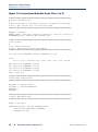
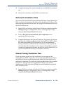
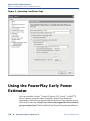
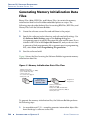
Creating Makefile Scripts
The Quartus II software supports makefile scripts that use the Quartus II
executables, which allow you to integrate your scripts with a wide variety of
scripting languages. Figure 13 shows an excerpt from a standard makefile
script.
ALTERA CORPORATION
INTRODUCTION TO QUARTUS II
■
27
CHAPTER 1: DESIGN FLOW
COMMAND-LINE DESIGN FLOW
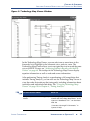
Figure 13. Excerpt from Makefile Script (Part 1 of 2)
###################################################################
# Project Configuration:
#
# Specify the name of the design (project) and Quartus II Settings
# File (.qsf) and the list of source files used.
###################################################################
PROJECT = chiptrip
SOURCE_FILES = auto_max.v chiptrip.v speed_ch.v tick_cnt.v time_cnt.v
ASSIGNMENT_FILES = chiptrip.qpf chiptrip.qsf
###################################################################
# Main Targets
#
# all: build everything
# clean: remove output files and database
###################################################################
all: smart.log $(PROJECT).asm.rpt $(PROJECT).tan.rpt
clean:
rm -rf *.rpt *.chg smart.log *.htm *.eqn *.pin *.sof *.pof db
map: smart.log $(PROJECT).map.rpt
fit: smart.log $(PROJECT).fit.rpt
asm: smart.log $(PROJECT).asm.rpt
tan: smart.log $(PROJECT).tan.rpt
smart: smart.log
###################################################################
# Executable Configuration
###################################################################
MAP_ARGS
FIT_ARGS
ASM_ARGS
TAN_ARGS
= --family=Stratix
= --part=EP1S20F484C6
=
=
###################################################################
# Target implementations
###################################################################
STAMP = echo done >
$(PROJECT).map.rpt: map.chg $(SOURCE_FILES)
quartus_map $(MAP_ARGS) $(PROJECT)
$(STAMP) fit.chg
28
■
INTRODUCTION TO QUARTUS II
ALTERA CORPORATION
CHAPTER 1: DESIGN FLOW
COMMAND-LINE DESIGN FLOW
Figure 13. Excerpt from Makefile Script (Part 2 of 2)
$(PROJECT).fit.rpt: fit.chg $(PROJECT).map.rpt
quartus_fit $(FIT_ARGS) $(PROJECT)
$(STAMP) asm.chg
$(STAMP) tan.chg
$(PROJECT).asm.rpt: asm.chg $(PROJECT).fit.rpt
quartus_asm $(ASM_ARGS) $(PROJECT)
$(PROJECT).tan.rpt: tan.chg $(PROJECT).fit.rpt
quartus_tan $(TAN_ARGS) $(PROJECT)
smart.log: $(ASSIGNMENT_FILES)
quartus_sh --determine_smart_action $(PROJECT) > smart.log
###################################################################
# Project initialization
###################################################################
$(ASSIGNMENT_FILES):
quartus_sh --prepare $(PROJECT)
map.chg:
$(STAMP)
fit.chg:
$(STAMP)
tan.chg:
$(STAMP)
asm.chg:
$(STAMP)
f
map.chg
fit.chg
tan.chg
asm.chg
For Information About
Refer To
Using Command-Line Executables
“Overview: Using Command-Line
Executables” in Quartus II Help
“Command-Line Scripting,” in the Quartus II
Handbook, vol. 2, on the Altera web site
Tcl Commands and Tcl Scripting
“Overview: Using Tcl from the User
Interface,” “Overview: Using Tcl Scripting,”
and “API Functions for Tcl” in Quartus II
Help
“Tcl Scripting,” in the Quartus II Handbook,
vol. 2, on the Altera web site
Quartus II Scripting Reference Manual on
the Altera web site
ALTERA CORPORATION
INTRODUCTION TO QUARTUS II
■
29
CHAPTER 1: DESIGN FLOW
DESIGN METHODOLOGIES & DESIGN PLANNING
Design Methodologies & Design
Planning
When you are creating a new design, it is important to consider the design
methodologies the Quartus II software offers. For example, the LogicLock
feature offers the ability to use top-down or bottom-up design
methodologies, top-down incremental compilation design flows, and blockbased design flows. You can use these design flows with or without EDA
design entry and synthesis tools.
Top-Down versus Bottom-Up Design
Methodologies
In the top-down design flow, there is only one output netlist for the entire
design, which may allow you to perform optimization across design
boundaries and hierarchies for the entire design, and is often simpler to
manage.
In the bottom-up design methodology, there are separate netlists for each
design module. This functionality allows you to compile each module
separately and apply different optimization techniques to each module.
Modifications to individual modules do not affect the optimizations to other
modules. The bottom-up design methodology also facilitates the reuse of
design modules in other designs.
Top-Down Incremental Compilation
Flow
The top-down incremental compilation flow allows you to preserve design
performance and save compilation time by reusing previous compilation
results and ensuring that only the parts of the design that have been
modified are recompiled. The top-down incremental compilation flow can
help you to improve timing by allowing you to change the placement of only
the critical elements of the design while processing the other design
partitions, or allowing you to specify the placement only for designated
portions of the design so that the Compiler can automatically optimize the
rest of the design.
30
■
INTRODUCTION TO QUARTUS II
ALTERA CORPORATION
CHAPTER 1: DESIGN FLOW
DESIGN METHODOLOGIES & DESIGN PLANNING
In the incremental compilation flow, you assign an instance of a design
entity to a design partition. You then assign the partitions to a physical
location on the device by using the Timing Closure Floorplan and the
LogicLock feature, and perform a full compilation of the design. During
compilation, the Compiler saves synthesis and fitting results in the project
database. After the first compilation, if you make additional changes to the
design, only the partitions that have changed require recompilation. When
you have finished making design changes, all the partitions are merged
together to allow you to perform a complete compilation. You can specify
whether you want to perform only an incremental synthesis, which can
reduce compilation time, or a full incremental compilation, which can
preserve performance in addition to significantly reducing compilation
time.
Since the incremental compilation flow prevents the Compiler from
optimizing across design partition boundaries, the Compiler may not be
able to perform as many optimizations for area and timing as would be
possible with regular compilation. To obtain best results for area and timing,
Altera recommends that you register the inputs and outputs of design
partitions, try to keep the number of design partitions to a reasonable
amount, avoid having too many critical paths that go beyond partition
boundaries, and avoid having partitions that are too small, such as smaller
than 1000 logic elements or Adaptive Logic Modules (ALMs).
For more information on assigning partitions and other stages of the
incremental compilation flow, see the following sections:
■
■
■
■
■
■
ALTERA CORPORATION
“Assigning Design Partitions” on page 62 in Chapter 3, “Constraint
Entry.”
“Performing Incremental Synthesis” on page 86 in Chapter 4,
“Synthesis.”
“Performing a Full Incremental Compilation” on page 92 in Chapter 5,
“Place & Route.”
“Using LogicLock Regions in Top-Down Incremental Compilation
Flows” on page 119 in Chapter 6, “Block-Based Design.”
“Using Incremental Compilation to Achieve Timing Closure” on page
172 in Chapter 9, “Timing Closure.”
“Using the SignalTap II Logic Analyzer with Incremental Compilation”
on page 202 in Chapter 12, “Debugging.”
INTRODUCTION TO QUARTUS II
■
31
CHAPTER 1: DESIGN FLOW
DESIGN METHODOLOGIES & DESIGN PLANNING
f
For Information About
Refer To
Using Quartus II incremental
compilation and incremental synthesis
and the incremental compilation flow
“Quartus II Incremental Compilation,” in the
Quartus II Handbook, vol. 1, on the Altera
web site
“Overview: Using Incremental Compilation”
and “Overview: Using Incremental
Synthesis” in Quartus II Help
Bottom-Up LogicLock-Based Design
Flow
In the bottom-up block-based LogicLock design flow, you can design and
optimize each module independently, integrate all optimized modules in a
top-level design, and then verify the overall design. Each module has a
separate netlist, which can then be incorporated after synthesis and
optimization into the top-level design. Each module in the top-level design
does not affect the performance of the other modules. The general blockbased design flow concepts can be used in modular, hierarchical,
incremental, and team-based design flows.
You can apply LogicLock constraints to individual nodes as well as to
hierarchical blocks; for example, you can make a wildcard path-based
LogicLock assignment on a critical path, which may be useful if the critical
path spans multiple design blocks.
You can use EDA design entry and synthesis tools in the block-based design
flow to design and synthesize individual modules, and then incorporate the
modules into a top-level design in the Quartus II software, or completely
design and synthesize a block-based design in EDA design entry and
synthesis tools. For more information on the block-based design flow, refer
to “Chapter 6: Block-Based Design” on page 113.
f
For Information About
Refer To
Using Quartus II incremental
compilation and incremental synthesis
“Quartus II Incremental Compilation,” in the
Quartus II Handbook, vol. 1, on the Altera
web site
“Overview: Using Incremental Compilation”
and “Overview: Using Incremental
Synthesis” in Quartus II Help
32
■
INTRODUCTION TO QUARTUS II
ALTERA CORPORATION
Chapter
Two
Design Entry
What’s in Chapter 2:
Introduction
34
Creating a Project
35
Creating a Design
43
Using Altera Megafunctions
47
2
CHAPTER 2: DESIGN ENTRY
INTRODUCTION
Introduction
A Quartus® II project includes all of the design files, software source files,
and other related files necessary for the successful operation of a design.
Using revisions allows you to compare multiple versions of settings and
assignments for your project, giving you the ability to meet design
requirements more quickly and efficiently. You can use the Quartus II Block
Editor, Text Editor, MegaWizard® Plug-In Manager (Tools menu), and EDA
design entry tools to create designs that include Altera® megafunctions,
library of parameterized modules (LPM) functions, and intellectual
property (IP) functions. Figure 1 shows the design entry flow.
Figure 1. Design Entry Flow
EDA Synthesis
Tool
MegaWizard Plug-In
Manager
EDIF netlist files (.edf)
or Verilog Quartus
Mapping Files (.vqm)
Verilog HDL &
VHDL design
files
Files generated by the
MegaWizard Plug-In
Manager
to
Quartus II
Analysis &
Synthesis
Quartus II
Text Editor
Text Design Files (.tdf) &
Verilog HDL & VHDL
design files (.v, .vhd)
Quartus II
Block Editor
Block Symbol Files (.bsf) &
MAX+PLUS II Symbol
Files (.sym)
Block Design Files (.bdf)
Quartus II
Symbol Editor
The Quartus II software also supports system-level design entry flows with
the Altera SOPC Builder and DSP Builder software. For more information
about these system-level design entry flows, refer to “Chapter 15: SystemLevel Design” on page 229.
34
■
INTRODUCTION TO QUARTUS II
ALTERA CORPORATION
CHAPTER 2: DESIGN ENTRY
CREATING A PROJECT
Creating a Project
You can create a new project by using the New Project Wizard (File menu)
or the quartus_map executable. When creating a new project, you specify
the working directory for the project, assign the project name, and designate
the name of the top-level design entity. You can also specify which design
files, other source files, user libraries, and EDA tools you want to use in the
project, as well as the target device (or allow the Quartus II software to
automatically select a device). Table 1 lists the project and settings files for a
Quartus II project.
Table 1. Quartus II Project Files
File Type
Description
Quartus II Project File (.qpf)
Specifies the version of the Quartus II software used to
create the project and the revisions associated with
the project.
Quartus II Settings
File (.qsf)
Contains all revision-wide or individual assignments
you made with the Assignment Editor, Floorplan
Editor, Settings dialog box (Assignments menu), Tcl
scripts, or Quartus II executables. There is one QSF for
each revision in the project.
Quartus II Workspace
File (.qws)
Contains user preferences and other information such
as the position of the windows, the open files and their
positions in the windows.
Quartus II Default Settings
File (.qdf)
Located in the \<Quartus II system directory>\bin
directory and contains all the global default project
settings. These settings are overridden by the settings
in the QSF.
Once you have created a project, you can add and remove design files and
other files from the project using the Settings dialog box (Assignments
menu). During Quartus II Analysis & Synthesis, the Quartus II software
processes the files in the order they appear in the Files page.
You can also copy an entire project to a new directory by using the Copy
Project command (Project menu). This command allows you to copy the
project design database files, design files, settings files, and report files to a
new directory and then open the project in the new directory. If the new
directory does not exist, the Quartus II software will create it.
ALTERA CORPORATION
INTRODUCTION TO QUARTUS II
■
35
CHAPTER 2: DESIGN ENTRY
CREATING A PROJECT
The Project Navigator displays information related to the current revision
and provides a graphical representation of the project hierarchy, files, and
design units, and shortcuts to various menu commands. You can also
customize the information shown in the Project Navigator with the
Customize Columns command (right button pop-up menu).
Figure 2. Project Navigator Window
The Project Navigator Window also allows you to assign design partitions.
For more information, see “Assigning Design Partitions” on page 62.
f
For Information About
Refer To
Creating and working with Quartus II
projects
“Overview: Using the New Project Wizard,”
“Overview: Using the Project Navigator,”
and “Overview: Working with Quartus II
Projects” in Quartus II Help
Design Entry module in the Quartus II
tutorial
Managing Quartus II projects
36
■
INTRODUCTION TO QUARTUS II
“Quartus II Project Management,” in the
Quartus II Handbook, vol. 2, on the Altera
web site
ALTERA CORPORATION
CHAPTER 2: DESIGN ENTRY
CREATING A PROJECT
Using Revisions
You can use revisions to specify, save, and use different groups of settings
and assignments for the design files in a design. Revisions allow you to
compare results using different settings and assignments for the same
design files in a design.
When you create a revision, the Quartus II software creates a separate QSF,
which contains all the settings and assignments related to that revision, and
places it in the top-level directory for the design. You can create a revision
for any entity in a design. You can view the top-level entity for the any
revision in the Revisions dialog box or the current top-level design entity in
the General page of the Settings dialog box (Assignments menu).
The Revisions dialog box (Project menu) allows you to view all the revisions
for the current project, create a revision for a specific design entity, delete a
revision, or set a particular revision as the current revision for compilation,
simulation, or timing analysis. The information in the Revisions dialog box
shows the top-level design entity for a particular revision and the family and
device selected for the revision. A check mark icon indicates the current
revision. Using the Create Revision dialog box, you can create a new
revision (based on an existing revision), enter a description for the revision,
copy the database used to create the revision, and set a revision as the
current revision. You can also select which columns appear in the Revisions
dialog box. See Figure 3.
ALTERA CORPORATION
INTRODUCTION TO QUARTUS II
■
37
CHAPTER 2: DESIGN ENTRY
CREATING A PROJECT
Figure 3. Revisions Dialog Box
Creating a revision does not affect the source design files for the project. You
can create a revision, set it as the current revision for the design, and then
make assignments and settings for the entity. This feature allows you to
create different settings and assignments for the same design entity and save
those settings as different revisions for comparison. Each revision has a
corresponding report file that you can open to view and compare the results
of the effects of settings and assignments changes against other revisions.
You can also use the Compare Revisions dialog box, which is available from
the Revisions dialog box, to compare the results of compilations with
different revisions. The Compare Revisions dialog box has a Results tab
and an Assignments tab. By default, the comparison shows all revisions for
the project, but you can also customize the comparison by selecting which
38
■
INTRODUCTION TO QUARTUS II
ALTERA CORPORATION
CHAPTER 2: DESIGN ENTRY
CREATING A PROJECT
revisions you want to display and adjusting the order. You can also export a
Comma-Separated Values File (.csv) from the comparison. Figure 4 shows
the Results tab of the Compare Revisions dialog box, which allows you to
compare the results of each revision.
Figure 4. Results Tab of Compare Revisions Dialog Box
Figure 5 shows the Assignments tab of the Compare Revisions dialog box,
which allows you to compare the assignment settings for each revision.
ALTERA CORPORATION
INTRODUCTION TO QUARTUS II
■
39
CHAPTER 2: DESIGN ENTRY
CREATING A PROJECT
Figure 5. Assignments Tab of Compare Revisions Dialog Box
f
40
■
For Information About
Refer To
Using revisions
“Quartus II Project Management,” in the
Quartus II Handbook, vol. 2, on the Altera
web site
Creating and using revisions
“Overview: Using Revisions” in Quartus II
Help
INTRODUCTION TO QUARTUS II
ALTERA CORPORATION
CHAPTER 2: DESIGN ENTRY
CREATING A PROJECT
Using Version-Compatible Databases
The Quartus II software allows you to export version-compatible database
files for use in a later version of the Quartus II software, eliminating the need
for a full compilation of the design in the later version of the Quartus II
software. You can export a database at any stage in the design flow, after
running Analysis & Synthesis or the quartus_map executable.
You can use this feature to create and optimize a design and then preserve
the database for Timing Analysis in a future version of the Quartus II
software to ensure that the design still meets the timing requirements with
updated timing models.
To export a database for use in a future version of the Quartus II software,
you can use the Export Database command (Project menu) to select the
directory to export the database. The Quartus II software exports the design
database. You can then use the Import Database command (Project menu)
in a future version of the Quartus II software to select the project folder,
import the design database, and perform timing analysis to verify the timing
requirements of the design.
You can also use the quartus_cdb command-line executable to export or
import design databases. Version-compatible databases are available in
version 4.1 or later versions of the Quartus II software.
!
Using the quartus_cdb executable
You can import or export version-compatible databases by using the quartus_cdb
executable.
To use the quartus_cdb executable to import or export a database, type one of the
following commands at a command prompt:
quartus_cdb <project> -c <revision> --import_database=<project directory>
quartus_cdb <project> -c <revision> --export_database=<project directory>
r
r
If you want to get help on the quartus_cdb executable, type one of the following
commands at the command prompt:
quartus_cdb -h r
quartus_cdb --help r
quartus_cdb --help=<topic name>
ALTERA CORPORATION
r
INTRODUCTION TO QUARTUS II
■
41
CHAPTER 2: DESIGN ENTRY
CREATING A PROJECT
f
For Information About
Refer To
Using version-compatible databases
“Quartus II Project Management,” in the
Quartus II Handbook, vol. 2, on the Altera
web site
Converting MAX+PLUS II Projects
The Convert MAX+PLUS II Project command (File menu) allows you to
select an existing MAX+PLUS II project’s Assignment & Configuration
File (.acf) or design file and convert it into a new Quartus II project that
contains all supported assignments and constraints from the original
MAX+PLUS II project. The Convert MAX+PLUS II Project command
automatically imports the MAX+PLUS II assignments and constraints,
creates new project files, and opens the new Quartus II project. Figure 6
shows the Convert MAX+PLUS II Project dialog box.
Figure 6. Convert MAX+PLUS II Project Dialog Box
f
For Information About
Refer To
Converting MAX+PLUS II projects
MAX+PLUS II Conversion module in the
Quartus II Tutorial
“Quartus II Design Flow for MAX+PLUS II
Users,” in the Quartus II Handbook, vol. 1,
on the Altera web site
42
■
INTRODUCTION TO QUARTUS II
ALTERA CORPORATION
CHAPTER 2: DESIGN ENTRY
CREATING A DESIGN
Creating a Design
You can use the Quartus II software to create a design in the Quartus II Block
Editor or use the Quartus II Text Editor to create an HDL design using the
AHDL, Verilog HDL, or VHDL design languages.
The Quartus II software also supports designs created from EDIF Input
Files (.edf) or Verilog Quartus Mapping Files (.vqm) generated by EDA
design entry and synthesis tools. You can also create Verilog HDL or VHDL
designs in EDA design entry tools, and either generate EDIF Input Files and
VQM Files, or use the Verilog HDL or VHDL design files directly in
Quartus II projects. For more information on using EDA synthesis tools to
generate EDIF Input Files or VQM Files, see “Using Other EDA Synthesis
Tools” on page 72 in Chapter 4, “Synthesis.”
You can use the design file types listed in Table 2 to create a design in the
Quartus II software or in EDA design entry tools.
Table 2. Supported Design File Types
Type
Description
Extension
Block Design File
A schematic design file created with the
Quartus II Block Editor.
.bdf
EDIF Input File
An EDIF version 2 0 0 netlist file,
generated by any standard EDIF netlist
writer.
.edf
.edif
Graphic Design File
A schematic design file created with the
MAX+PLUS II Graphic Editor.
.gdf
Text Design File
A design file written in the Altera
Hardware Description Language (AHDL).
.tdf
Verilog Design File
A design file that contains design logic
defined with Verilog HDL.
.v
.vlg
.verilog
VHDL Design File
A design file that contains design logic
defined with VHDL.
.vh
.vhd
.vhdl
Verilog Quartus
Mapping File
A Verilog HDL–format netlist file
generated by the Synplicity Synplify
software or the Quartus II software.
.vqm
ALTERA CORPORATION
INTRODUCTION TO QUARTUS II
■
43
CHAPTER 2: DESIGN ENTRY
CREATING A DESIGN
Using the Quartus II Block Editor
The Block Editor allows you to enter and edit graphic design information in
the form of schematics and block diagrams. The Quartus II Block Editor
reads and edits Block Design Files and MAX+PLUS II Graphic Design Files.
You can open Graphic Design Files in the Quartus II software and save them
as Block Design Files. The Block Editor is similar to the Graphic Editor from
the MAX+PLUS II software.
Each Block Design File contains blocks and symbols that represent logic in
the design. The Block Editor incorporates the design logic represented by
each block diagram, schematic, or symbol into the project.
You can create new design files from blocks in a Block Design File, update
the design files when you modify the blocks and the symbols, and generate
Block Symbol Files (.bsf), AHDL Include Files (.inc), and HDL files from
Block Design Files. You can also analyze the Block Design Files for errors
before compilation. The Block Editor also provides a set of tools that help
you connect blocks and primitives in a Block Design File, including bus and
node connections and signal name mapping.
You can change the Block Editor to display options, such as guidelines and
grid spacing, rubberbanding, colors and screen elements, zoom, and
different block and primitive properties to suit your preferences.
You can use the following features of the Block Editor to assist in creating a
Block Design File in the Quartus II software:
44
■
■
Instantiate Altera-provided megafunctions: The MegaWizard PlugIn Manager (Tools menu) allows you to create or modify design files
that contain custom variations of megafunctions. These custom
megafunction variations are based on Altera-provided megafunctions,
including LPM functions. Megafunctions are represented by blocks in
Block Design Files. See “Using the MegaWizard Plug-In Manager” on
page 49.
■
Insert block and primitive symbols: Block diagrams use rectangularshaped symbols, called blocks, to represent design entities and the
corresponding assigned signals, and are useful in top-down design.
Blocks are connected by conduits that represent the flow of the
corresponding signals. You can use block diagrams exclusively to
represent your design, or you can combine them with schematic
elements.
INTRODUCTION TO QUARTUS II
ALTERA CORPORATION
CHAPTER 2: DESIGN ENTRY
CREATING A DESIGN
The Quartus II software provides symbols for a variety of logic
functions—including primitives, library of parameterized modules
(LPM) functions, and other megafunctions—that you can use in the
Block Editor.
■
Create files from blocks or Block Design Files: To facilitate
hierarchical projects, you can use the Create/Update command (File
menu) in the Block Editor to create other Block Design Files, AHDL
Include Files, Verilog HDL and VHDL design files, and Quartus II
Block Symbol Files from blocks within a Block Design File. You can also
create Verilog Design Files, VHDL Design Files, and Block Symbol Files
from a Block Design File itself.
Using the Quartus II Text Editor
The Quartus II Text Editor is a flexible tool for entering text-based designs in
the AHDL, VHDL, and Verilog HDL languages, and the Tcl scripting
language. You can also use the Text Editor to enter, edit, and view other
ASCII text files, including those created for or by the Quartus II software.
The Text Editor also allows you to insert a template for any AHDL statement
or section, Tcl command, or supported VHDL or Verilog HDL construct into
the current file. AHDL, VHDL, and Verilog HDL templates provide an easy
way for you to enter HDL syntax, increasing the speed and accuracy of
design entry. You can also get context-sensitive help on all AHDL elements,
keywords, and statements, as well as on megafunctions and primitives.
Using the Quartus II Symbol Editor
The Symbol Editor allows you to view and edit predefined symbols that
represent macrofunctions, megafunctions, primitives, or design files. Each
Symbol Editor file represents one symbol. For each symbol file, you can
choose from libraries containing Altera megafunctions and LPM functions.
You can customize these Block Symbol Files and then add the symbols to
schematics created with the Block Editor. The Symbol Editor reads and edits
Block Symbol Files and MAX+PLUS II Symbol Files (.sym) and saves both
types of files as Block Symbol Files.
ALTERA CORPORATION
INTRODUCTION TO QUARTUS II
■
45
CHAPTER 2: DESIGN ENTRY
CREATING A DESIGN
Using Verilog HDL, VHDL & AHDL
You can use the Quartus II Text Editor or another text editor to create Text
Design Files, Verilog Design Files, and VHDL Design Files, and combine
them with other types of design files in a hierarchical design.
Verilog Design Files and VHDL Design Files can contain any combination of
Quartus II–supported constructs. They can also contain Altera-provided
logic functions, including primitives and megafunctions, and user-defined
logic functions.
In the Text Editor, you use the Create/Update command (File menu) to
create a Block Symbol File from the current Verilog HDL or VHDL design
file and then incorporate it into a Block Design File. Similarly, you can create
an AHDL Include File that represents a Verilog HDL or VHDL design file
and incorporate it into an Text Design File or another Verilog HDL or VHDL
design file.
For VHDL designs, you can specify the name of a VHDL library for a design
in the Properties dialog box that is available from the Files page of the
Settings dialog box (Assignments menu) or from the Files tab of the Project
Navigator.
For more information on using the Verilog HDL and VHDL languages in the
Quartus II software, see “Using Quartus II Verilog HDL & VHDL Integrated
Synthesis” on page 69 in Chapter 4, “Synthesis.”
AHDL is a high-level, modular language that is completely integrated into
the Quartus II system. AHDL supports Boolean equation, state machine,
conditional, and decode logic. AHDL also allows you to create and use
parameterized functions, and includes full support for LPM functions.
AHDL is especially well suited for designing complex combinational logic,
group operations, state machines, truth tables, and parameterized logic.
f
46
■
For Information About
Refer To
Using the Quartus II Block Editor and
Symbol Editor
“Block Editor & Symbol Editor Introduction”
in Quartus II Help
Using the Quartus II Text Editor
“Text Editor Introduction” in Quartus II Help
Creating designs in the Quartus II
software
Design Entry module in the Quartus II
Tutorial
INTRODUCTION TO QUARTUS II
ALTERA CORPORATION
CHAPTER 2: DESIGN ENTRY
USING ALTERA MEGAFUNCTIONS
Using Altera Megafunctions
Altera megafunctions are complex or high-level building blocks that can be
used together with gate and flipflop primitives in Quartus II design files.
The parameterizable megafunctions and LPM functions provided by Altera
are optimized for Altera device architectures. You must use megafunctions
to access some Altera device-specific features, such as memory, DSP blocks,
LVDS drivers, PLLs, and SERDES and DDIO circuitry.
You can use the MegaWizard Plug-In Manager (Tools menu) to create
Altera megafunctions, LPM functions, and IP functions for use in designs in
the Quartus II software and EDA design entry and synthesis tools. Table 3
shows the types of Altera-provided megafunctions and LPM functions that
you can create using the MegaWizard Plug-In Manager.
Table 3. Altera-Provided Megafunctions & LPM Functions
Type
Description
Arithmetic
Components
Includes accumulators, adders, multipliers, and LPM arithmetic
functions.
Gates
Includes multiplexers and LPM gate functions.
I/O Components
Includes Clock Data Recovery (CDR), phase-locked loop (PLL),
double data rate (DDR), gigabit transceiver block (GXB), LVDS
receiver and transmitter, PLL reconfiguration, and remote
update megafunctions.
Memory Compiler
Includes the FIFO Partitioner, RAM, and ROM megafunctions.
Storage Components
Memory and shift register megafunctions, and LPM memory
functions.
To save valuable design time, Altera recommends using megafunctions
instead of coding your own logic. Additionally, these functions can offer
more efficient logic synthesis and device implementation. It is easy to scale
megafunctions to different sizes by simply setting parameters. Altera also
provides AHDL Include Files and VHDL Component Declarations for both
Altera-provided megafunctions and LPM functions.
ALTERA CORPORATION
INTRODUCTION TO QUARTUS II
■
47
CHAPTER 2: DESIGN ENTRY
USING ALTERA MEGAFUNCTIONS
f
For Information About
Refer To
Using the MegaWizard Plug-In Manager
“Overview: Using the MegaWizard Plug-In
Manager” in Quartus II Help
Design Entry module in the Quartus II
Tutorial
Using Intellectual Property (IP)
Megafunctions
Altera provides several methods for obtaining both Altera Megafunction
Partners Program (AMPP™) and MegaCore® megafunctions, functions that
are rigorously tested and optimized for the highest performance in Altera
device-specific architectures. You can use these parameterized blocks of
intellectual property to reduce design and test time. MegaCore and AMPP
megafunctions include megafunctions for embedded processors, interfaces
and peripherals, digital signal processing (DSP), and communications
applications.
Altera provides the following programs, features, and functions to assist
you in using IP functions in the Quartus II software and EDA design entry
tools:
■
AMPP Program: The AMPP program offers support to third-party
vendors to create and distribute megafunctions for use with the
Quartus II software. AMPP partners offer a large selection of off-theshelf megafunctions that are optimized for Altera devices.
Evaluation periods for AMPP functions are determined by the
individual vendors. You can download and evaluate AMPP functions
through the IP MegaStore™ on the Altera web site at
www.altera.com/ipmegastore.
■
48
■
MegaCore Functions: MegaCore functions are pre-designed,
optimized, and verified design files for complex system-level functions,
and are fully parameterizable using the MegaWizard Plug-In Manager
and IP Toolbench. IP Toolbench is a toolbar that you can use to quickly
and easily view documentation, specify parameters, set up other EDA
tools, and generate all the files necessary for integrating a
parameterized MegaCore function into your design.
INTRODUCTION TO QUARTUS II
ALTERA CORPORATION
CHAPTER 2: DESIGN ENTRY
USING ALTERA MEGAFUNCTIONS
You can install MegaCore functions from the MegaCore IP Library
CD-ROM either during or after installation of the Quartus II software.
You can also download individual IP MegaCore functions from the
Altera web site, via the IP MegaStore, and install them separately. You
can also access MegaCore functions though the MegaWizard Portal
Extension to the MegaWizard Plug-In Manager.
■
OpenCore Evaluation Feature: The OpenCore® evaluation feature
allows you to evaluate AMPP functions before purchase. You can use
the OpenCore feature to compile, simulate, and verify the performance
of a design, but it does not support programming file generation.
■
OpenCore Plus Hardware Evaluation Feature: The free OpenCore
Plus hardware evaluation feature allows you to simulate the behavior
of a MegaCore function within your system, verify the functionality of
the design, and evaluate its size and speed quickly and easily. In
addition, the Quartus II software generates time-limited programming
files for designs containing MegaCore functions, allowing you to
program devices and verify your design in hardware before purchasing
a license for the IP megafunction.
When the OpenCore Plus hardware feature is turned on in the
Compilation Process page of the Settings dialog box (Assignments
menu), the Quartus II software inserts a small amount of control logic.
This logic can have an adverse effect on fitting, especially with small
devices. You can turn off the OpenCore Plus hardware evaluation
feature to direct the Quartus II software to omit the additional logic.
Using the MegaWizard Plug-In
Manager
The MegaWizard Plug-In Manager helps you create or modify design files
that contain custom megafunction variations, which you can then instantiate
in a design file. These custom megafunction variations are based on Alteraprovided megafunctions, including LPM, MegaCore, and AMPP functions.
The MegaWizard Plug-In Manager runs a wizard that helps you easily
specify options for the custom megafunction variations. The wizard allows
you to set values for parameters and optional ports. You can open the
MegaWizard Plug-In Manager from the Tools menu or from within a Block
Design File, or you can run it as a stand-alone utility. Table 4 lists the files
generated by the MegaWizard Plug-In Manager for each custom
megafunction variation you generate.
ALTERA CORPORATION
INTRODUCTION TO QUARTUS II
■
49
CHAPTER 2: DESIGN ENTRY
USING ALTERA MEGAFUNCTIONS
Table 4. Files Generated by the MegaWizard Plug-In Manager
File Name
Description
<output file>.bsf
Symbol for the megafunction used in the Block Editor.
<output file>.cmp
Component Declaration File.
<output file>.inc
AHDL Include File for the module in the megafunction wrapper
file.
<output file>.tdf
Megafunction wrapper file for instantiation in an AHDL design.
<output file>.vhd
Megafunction wrapper file for instantiation in a VHDL design.
<output file>.v
Megafunction wrapper file for instantiation in a Verilog HDL
design.
<output file>_bb.v
Hollow-body or black box declaration of the module in the
megafunction wrapper file used in Verilog HDL designs to
specify port directions when using EDA synthesis tools.
<output file>_inst.tdf
Sample AHDL instantiation of the subdesign in the
megafunction wrapper file.
<output file>_inst.vhd
Sample VHDL instantiation of the entity in the megafunction
wrapper file.
<output file>_inst.v
Sample Verilog HDL instantiation of the module in the
megafunction wrapper file.
!
Using the Stand-Alone MegaWizard Plug-In Manager
You can use the MegaWizard Plug-In Manager from outside the Quartus II
software by typing the following command at a command prompt:
qmegawiz
r
Instantiating Megafunctions in the
Quartus II Software
You can instantiate Altera megafunctions and LPM functions in the
Quartus II software through direct instantiation in the Block Editor, through
instantiation in HDL code (either by instantiating through the port and
parameter definition or by using the MegaWizard Plug-In Manager to
parameterize the megafunction and create a wrapper file), or through
inference.
50
■
INTRODUCTION TO QUARTUS II
ALTERA CORPORATION
CHAPTER 2: DESIGN ENTRY
USING ALTERA MEGAFUNCTIONS
Altera recommends that you use the MegaWizard Plug-In Manager to
instantiate megafunctions and create custom megafunction variations. The
wizard provides a graphical interface for customizing and parameterizing
megafunctions, and ensures that you set all megafunction parameters
correctly.
Instantiation in Verilog HDL & VHDL
You can use the MegaWizard Plug-In Manager to create a megafunction or
a custom megafunction variation. The MegaWizard Plug-In Manager then
creates a Verilog HDL or VHDL wrapper file that contains an instance of the
megafunction, which you can then use in your design. For VHDL
megafunctions, the MegaWizard Plug-In Manager also creates a
Component Declaration File.
Using the Port & Parameter Definition
You can instantiate the megafunction directly in your Verilog HDL or VHDL
design by calling the function like any other module or component. In
VHDL, you also need to use a Component Declaration.
Inferring Megafunctions
Quartus II Analysis & Synthesis automatically recognizes certain types of
HDL code and infers the appropriate megafunction. The Quartus II software
uses inference because Altera megafunctions are optimized for Altera
devices, and performance may be better than standard HDL code. For some
architecture-specific features, such as RAM and DSP blocks, you must use
Altera megafunctions.
The Quartus II software maps the following logic to megafunctions during
synthesis:
■
■
■
■
■
■
ALTERA CORPORATION
Counters
Adders/Subtractors
Multipliers
Multiply-accumulators and multiply-adders
RAM
Shift registers
INTRODUCTION TO QUARTUS II
■
51
CHAPTER 2: DESIGN ENTRY
USING ALTERA MEGAFUNCTIONS
Instantiating Megafunctions in EDA
Tools
You can use Altera-provided megafunctions, LPM functions, and IP
functions in EDA design entry and synthesis tools. You can instantiate
megafunctions in EDA tools by creating a black box for the function, by
inference, or by using the clear box methodology.
Using the Black Box Methodology
You can use the MegaWizard Plug-In Manager to generate Verilog HDL or
VHDL wrapper files for megafunctions. For Verilog HDL designs, the
MegaWizard Plug-In Manager also generates a Verilog Design File that
contains a hollow-body declaration of the module, used to specify port
directions.
The Verilog HDL or VHDL wrapper file contains the ports and parameters
for the megafunction, which you can use to instantiate the megafunction in
the top-level design file as well as a sample instantiation file and then direct
the EDA tool to treat the megafunction as a black box during synthesis.
The following steps describe the basic flow for using the MegaWizard
Plug-In Manager to create a black box for an Altera megafunction or LPM
function in EDA design entry and synthesis tools:
52
■
1.
Use the MegaWizard Plug-In Manager to create and parameterize the
megafunction or LPM function.
2.
Use the black box file or component declaration (along with the sample
instantiation file) generated by the MegaWizard Plug-In Manager to
instantiate the function in the EDA synthesis tool.
3.
Perform synthesis and optimization of the design in the EDA synthesis
tool. The EDA synthesis tool treats the megafunction as a black box
during synthesis.
INTRODUCTION TO QUARTUS II
ALTERA CORPORATION
CHAPTER 2: DESIGN ENTRY
USING ALTERA MEGAFUNCTIONS
Instantiation by Inference
EDA synthesis tools automatically recognize certain types of HDL code and
infer the appropriate megafunction.You can directly instantiate memory
blocks (RAM and ROM), DSP blocks, shift registers, and some arithmetic
components in Verilog HDL or VHDL code. The EDA tool then maps the
logic to the appropriate Altera megafunction during synthesis.
Using the Clear Box Methodology
In the black box flow, an EDA synthesis tool treats Altera megafunctions and
LPM functions as black boxes. As a result, the EDA synthesis tool cannot
fully synthesize and optimize designs with Altera megafunctions, because
the tool does not have a full model or timing information for the function.
Using the clear box flow, you can use the MegaWizard Plug-In Manager to
create a fully synthesizeable Altera megafunction or LPM function for use
with EDA synthesis tools.
The following steps describe the basic flow for using clear box
megafunctions with EDA synthesis tools:
1.
Use the MegaWizard Plug-In Manager to create and parameterize the
megafunction or LPM function. Make sure you turn on Generate a
Clearbox body in the MegaWizard Plug-In Manager.
2.
Use the Verilog or VHDL design file generated by the MegaWizard
Plug-In Manager to instantiate the function in the EDA synthesis tool.
3.
Perform synthesis and optimization of the design in the EDA synthesis
tool.
Using of the clear box methodology generally results in slower simulation
times in EDA simulation tools (but not the Quartus II Simulator), due to the
level of detail (timing information and device resources used) that is
included with a clear box megafunction or LPM function. In addition,
specific device details are included in the clear box megafunction or LPM
function, so that to use a different device for the design, the clear box
function needs to be regenerated for the new device.
ALTERA CORPORATION
INTRODUCTION TO QUARTUS II
■
53
CHAPTER 2: DESIGN ENTRY
USING ALTERA MEGAFUNCTIONS
f
For Information About
Refer To
List of ports and parameters for a
megafunction
If you are using an IP function, refer to the
IP documentation. For Altera
megafunctions, refer to Quartus II Help.
Using Altera-provided megafunctions
and LPM functions in EDA tools
“Overview: Creating & Instantiating AlteraProvided Functions in Other EDA Tools” in
Quartus II Help
“Synplicity Synplify and Synplify Pro
Support,” in the Quartus II Handbook,
vol. 1, on the Altera web site
“Mentor Graphics LeonardoSpectrum
Support,” in the Quartus II Handbook,
vol. 1, on the Altera web site
“Mentor Graphics Precision RTL Synthesis
Support,” in the Quartus II Handbook,
vol. 1, on the Altera web site
“Synopsys Design Compiler FPGA Support,”
in the Quartus II Handbook, vol. 1, on the
Altera web site
Using Altera-provided megafunctions
and LPM functions in the Quartus II
software
Design Entry module in the Quartus II
Tutorial
Using the MegaWizard Plug-In
Manager and Altera-provided
megafunctions and LPM functions
“Overview: Using the MegaWizard Plug-In
Manager” in Quartus II Help
MegaCore functions and OpenCore
Plus hardware evaluation feature
Application Note 343 (OpenCore Evaluation
of AMPP Megafunctions) on the Altera web
site
Application Note 320 (OpenCore Plus
Evaluation of Megafunctions) on the Altera
web site
Using IP Functional Simulation Models to
Verify Your System Design white paper on
the Altera web site
54
■
INTRODUCTION TO QUARTUS II
ALTERA CORPORATION
Chapter
Three
Constraint Entry
What’s in Chapter 3:
Introduction
56
Using the Assignment Editor
57
Using the Pin Planner
59
Using the Settings Dialog Box
60
Assigning Design Partitions
62
Importing Assignments
64
Verifying Pin Assignments
65
3
CHAPTER 3: CONSTRAINT ENTRY
INTRODUCTION
Introduction
Once you have created a project and your design, you can use the
Quartus® II Settings dialog box (Assignments menu), Assignment Editor,
Pin Planner, Design Partitions window, and Timing Closure floorplan to
specify initial design constraints, such as pin assignments, device options,
logic options, and timing constraints. You can import assignments using the
Import Assignments command (Assignments menu) or export assignments
using the Export command (File menu). You can also import assignments
from other EDA synthesis tools using Tcl commands or scripts. The
Quartus II software also provides the Timing wizard (Assignments menu)
to assist in specifying initial timing constraints. Many of the settings
available from the Assign command in the MAX+PLUS® II quick menu can
be made in the Assignment Editor and Settings dialog box. Figure 1 shows
the constraint and assignment entry flow.
Figure 1. Constraint & Assignment Entry Flow
Quartus II
Settings Dialog Box
Quartus II
design files
Quartus II
Assignment Editor
Quartus II
Project File (.qpf)
Quartus II
Pin Planner
Quartus II
Settings File (.qsf)
Quartus II
Design Partitions
Window
Quartus II
Timing Closure
Floorplan
56
■
to Quartus II
Analysis & Synthesis
Verilog Quartus Mapping
Files (.vqm) & Quartus
Settings File (.qsf)
from Block-Based
Design
INTRODUCTION TO QUARTUS II
ALTERA CORPORATION
CHAPTER 3: CONSTRAINT ENTRY
USING THE ASSIGNMENT EDITOR
Using the Assignment Editor
The Assignment Editor is the interface for creating and editing node and
entity-level assignments in the Quartus II software. Assignments allow you
to specify various options and settings for the logic in your design, including
location, I/O standard, timing, logic option, parameter, simulation, and pin
assignments.
Using the Assignment Editor, you can select an assignment category; use the
Quartus II Node Finder to select specific nodes and entities to assign;
display information about specific assignments; and add, edit, or delete
assignments for selected nodes. You can enable or disable individual
assignments, and you can also add comments to an assignment.
The following steps illustrate the basic flow for using the Assignment Editor
to make assignments:
1.
Open the Assignment Editor.
2.
Select the appropriate category assignment in the Category bar.
3.
Specify the appropriate node or entity in the Node Filter bar, or use the
Node Finder dialog box to find a specific node or entity.
4.
In the spreadsheet that displays the assignments for the current design,
add the appropriate assignment information.
The spreadsheet in the Assignment Editor provides applicable drop-down
lists or allows you to type assignment information. As you add, edit, and
remove assignments, the corresponding Tcl command appears in the
Messages window.
You can use the Export command (File menu) to export the data from the
Assignment Editor to a Tcl Script File (.tcl) or a Comma-Separated Value
File (.csv). You can also import assignments data from a CSV or text file
using the Import Assignments command (Assignments menu). For more
information about importing assignments, see “Importing Assignments” on
page 64.
When creating and editing assignments, the Quartus II software
dynamically validates the assignment information where possible. If an
assignment or assignment value is illegal, the Quartus II software does not
add or update the value, and instead reverts to the current value or does not
accept the value. When you view all assignments, the Assignment Editor
ALTERA CORPORATION
INTRODUCTION TO QUARTUS II
■
57
CHAPTER 3: CONSTRAINT ENTRY
USING THE ASSIGNMENT EDITOR
shows all assignments created for the current project that are valid for the
current device, but when you view individual assignment categories, the
Assignment Editor displays only the assignments that are related to the
specific category selected.
Figure 2. The Quartus II Assignment Editor
f
For Information About
Refer To
Using the Assignment Editor
“Assignment Editor,” in the Quartus II
Handbook, vol. 2, on the Altera web site
“Assignment Editor Introduction” and
“Overview: Making Assignments” in
Quartus II Help
58
■
INTRODUCTION TO QUARTUS II
ALTERA CORPORATION
CHAPTER 3: CONSTRAINT ENTRY
USING THE PIN PLANNER
Using the Pin Planner
The Pin Planner, which is available from the Assignments menu, is a visual
tool that provides another way for you to make assignments to pins and
groups of pins. It includes a package view of the device with different colors
and symbols that represent the different types of pins and additional
symbols that represent I/O banks. The symbols used in the Pin Planner are
very similar to the symbols used in device family data sheets. It also includes
tables of assigned and unassigned pins. Figure 3 shows the Pin Planner
window.
Figure 3. Pin Planner
Unassigned pins table
Package view
Assigned pins table
By default, the Pin Planner displays a list of unassigned pins, which includes
columns for node name, direction, and type; a package view diagram of the
device; and a list of assigned pins, which includes columns for node name,
pin location, and I/O bank. You can make pin assignments by dragging one
ALTERA CORPORATION
INTRODUCTION TO QUARTUS II
■
59
CHAPTER 3: CONSTRAINT ENTRY
USING THE SETTINGS DIALOG BOX
or more pins from the Unassigned Pins table to available pin or I/O bank
locations in the package diagram. In the Assigned Pins table, you can filter
the node names, change the I/O standards, and specify options for reserved
pins. In the Unassigned Pins table, you can change the node name and
direction for user-added nodes. You can also specify options for reserved
pins. If you want, you can also turn off the lists of assigned and unassigned
pins.
In the Pin Planner window, you can adjust the view and zoom in and out.
You can choose whether to display I/O banks, VREF groups, assignable
I/O pins, or differential pin pair connections. You can also display the
properties and available resources for the selected pin, and can display a
legend that explains the different colors and symbols that are used in the Pin
Planner.
f
For Information About
Refer To
Using the Pin Planner to assign pins
“I/O Planning using the Pin Planner,” in the
Quartus II Handbook, vol. 2, on the Altera
web site
Using the Settings Dialog Box
You can use the Settings dialog box (Assignments menu) to specify
assignments and options for your project. You can set general project-wide
options and synthesis, fitting, simulation, and timing analysis options.
Using the Settings dialog box, you can perform the following types of tasks:
60
■
■
Modify project settings: specify and view the current top-level entity
for project and revision information; add and remove files from the
project; specify custom user libraries; specify device options for
package, pin count, and speed grade; and specify migration devices.
■
Specify EDA tool settings: specify EDA tools for design entry/
synthesis, simulation, timing analysis, board-level verification, formal
verification, physical synthesis, and related tool options.
■
Specify Analysis & Synthesis settings: project-wide settings for
Analysis & Synthesis, Verilog HDL and VHDL input settings, default
design parameters, and synthesis netlist optimizations options.
INTRODUCTION TO QUARTUS II
ALTERA CORPORATION
CHAPTER 3: CONSTRAINT ENTRY
USING THE SETTINGS DIALOG BOX
f
■
Specify compilation process settings: options for smart compilation,
preserving node names, running the Assembler during compilation,
incremental compilation or incremental synthesis, saving node-level
netlists, exporting version-compatible databases, displaying entity
names, and enabling or disabling the OpenCore® Plus evaluation
feature. Also provides options for generating an early timing estimate.
■
Specify fitting settings: timing-driven compilation options, Fitter
effort, project-wide Fitter logic options assignments, and physical
synthesis netlist optimizations.
■
Specify timing analysis settings: default frequencies for the project or
define individual clock settings, delay requirements and path-cutting
options, and timing analysis reporting options.
■
Specify Simulator settings: mode (functional or timing), source vector
file, simulation period, and simulation detection options.
■
Specify PowerPlay Power Analyzer settings: input file type, output
file type, and default toggle rates, as well as operating conditions such
as junction temperature, cooling solution requirements, and device
characteristics.
■
Specify software build settings: toolset directories, processor
architecture and software toolset, compiler, assembler, and linker
settings.
■
Specify Design Assistant, SignalTap II, SignalProbe, and HardCopy
settings: turn on the Design Assistant and select rules; enable the
SignalTap® II Logic Analyzer and specify a SignalTap II File (.stp)
name; specify options for automatically routing SignalProbe™ signals
and modifying fitting results for the SignalProbe feature; and specify
options for HardCopy™ timing and generating HardCopy files.
For Information About
Refer To
Assigning project-wide settings with
the Settings dialog box
“Overview: Making Assignments” in
Quartus II Help
ALTERA CORPORATION
INTRODUCTION TO QUARTUS II
■
61
CHAPTER 3: CONSTRAINT ENTRY
ASSIGNING DESIGN PARTITIONS
Assigning Design Partitions
If you want to use the incremental compilation or incremental synthesis
features, you can designate separate hierarchical sections of your design as
design partitions on which you can perform Analysis & Synthesis or a full
compilation incrementally, without affecting the rest of the project. For more
information about incremental compilation and incremental synthesis, see
the following sections:
■
■
■
“Top-Down Incremental Compilation Flow” on page 30 in Chapter 1,
“Design Flow.”
“Performing Incremental Synthesis” on page 86 in Chapter 4,
“Synthesis.”
“Performing a Full Incremental Compilation” on page 92 in Chapter 5,
“Place & Route.”
You can assign partitions in your design for use with incremental synthesis
or full incremental compilation. Both the Project Navigator and the Design
Partitions window allow you to assign design partitions.
Assigning Design Partitions in the
Project Navigator
In the Hierarchy tab of the Project Navigator, you can specify a selected
instance of an entity as a design partition by using the Set as Design
Partition command (right button pop-up menu). When you specify the first
partition for the project, you are asked whether you want to use incremental
synthesis only or full incremental compilation, or whether you want to leave
this feature currently disabled.
If you want to make a LogicLock™ assignment for a partition, you can drag
the partition from the Project Navigator window directly to the LogicLock
Regions window or to a LogicLock region in the Timing Closure floorplan.
62
■
INTRODUCTION TO QUARTUS II
ALTERA CORPORATION
CHAPTER 3: CONSTRAINT ENTRY
ASSIGNING DESIGN PARTITIONS
Assigning Design Partitions with the
Design Partitions Window
You can specify an entity as a design partition with the Design Partitions
Window command (Assignments menu). Figure 4 shows the Design
Partitions window.
Figure 4. Design Partitions Window
In the Design Partitions window, you can specify which of the following
incremental compilation modes to use:
■
■
■
Incremental Synthesis only
Full Incremental Compilation
Off
You can use the right button pop-up menu to rename the partition if you
want to use a name other than the full hierarchy path name. You can also
generate an incremental compilation Tcl script by choosing Generate
Incremental Compilation Tcl Script (right button pop-up menu).
If your Incremental Compilation Mode is Full Incremental Design, the
Design Partitions window also displays the Netlist Type column and allows
you to specify one of the following options for Netlist Type:
■
■
■
■
ALTERA CORPORATION
Source File directs the Compiler to compile from source design files.
Post-Synthesis preserves synthesis results for the partition (this is the
default option for new partitions)
Post-Fit preserves placement results for the partition
Empty skips compilation for the partition
INTRODUCTION TO QUARTUS II
■
63
CHAPTER 3: CONSTRAINT ENTRY
IMPORTING ASSIGNMENTS
You can specify the netlist type by selecting the type from the list in the
Netlist Type column or by selecting the partition and choosing Properties
(right button pop-up menu).
If you want to make a LogicLock assignment for a partition, you can drag the
partition from the Design Partitions window directly to the LogicLock
Regions window or to a LogicLock region in the Timing Closure floorplan.
f
For Information About
Refer To
Assigning design partitions and using
incremental compilation
“Quartus II Incremental Compilation Flow,”
in the Quartus II Handbook, vol. 1, on the
Altera web site
Importing Assignments
The Import Assignments command (Assignments menu) allows you to
import assignments from projects created in the Quartus II software or the
MAX+PLUS II software into a project in the Quartus II software.
The Import Assignments dialog box allows you to specify the file that
contains the assignments to import and the specific types of assignments
(Assignment Categories) to import into the QSF for the current project
revision. Click Advanced in the Import Assignments dialog box to specify
the nature of the assignments to import, specify global or instance-level
assignments to import, and specify how the assignments affect the current
design. You can use this dialog box to import settings files, CSV Files created
with the Export command (File menu), and FPGA Xchange Files (.fx), and
can create a backup of the current QSF for the design before importing
assignments. See Figure 5.
64
■
INTRODUCTION TO QUARTUS II
ALTERA CORPORATION
CHAPTER 3: CONSTRAINT ENTRY
VERIFYING PIN ASSIGNMENTS
Figure 5. Import Assignments Dialog Box
You can use this command to import the MAX+PLUS II Assignment &
Configuration File, which contains MAX+PLUS II project assignments and
settings, into your Quartus II project. You can also use this command to
import settings and assignments from other projects created in the
Quartus II software into your current project. For example, you can use this
command to import pin assignments from a previous Quartus II project into
the current Quartus II project.
For more information on using the Import Assignments command to
import LogicLock™ region assignments, refer to “Saving Intermediate
Synthesis Results for Bottom-Up LogicLock Flows” on page 120 in Chapter
6, “Block-Based Design.”
f
For Information About
Refer To
Importing Assignments
“Importing Assignments” in Quartus II Help
Verifying Pin Assignments
The Quartus II software allows you to verify pin assignments—location,
I/O bank, and I/O standard assignments—with the Start > Start I/O
Assignment Analysis command (Processing menu). You can use this
command at any stage of the design process to verify the accuracy of the
ALTERA CORPORATION
INTRODUCTION TO QUARTUS II
■
65
CHAPTER 3: CONSTRAINT ENTRY
VERIFYING PIN ASSIGNMENTS
assignments, allowing you to create your final pin-out faster. You do not
need design files to use this command, and can verify pin-outs before design
compilation.
f
66
■
For Information About
Refer To
Importing Assignments
“I/O Assignment Planning and Analysis,” in
the Quartus II Handbook, vol. 2, on the
Altera web site
INTRODUCTION TO QUARTUS II
ALTERA CORPORATION
Chapter
Four
Synthesis
What’s in Chapter 4:
Introduction
68
Using Quartus II Verilog HDL & VHDL
Integrated Synthesis
69
Using Other EDA Synthesis Tools
72
Controlling Analysis & Synthesis
75
Using the Design Assistant to Check
Design Reliability
79
Analyzing Synthesis Results with the
RTL Viewer
80
Analyzing Synthesis Results with the
Technology Map Viewer
84
Performing Incremental Synthesis
86
4
CHAPTER 4: SYNTHESIS
INTRODUCTION
Introduction
You can use the Quartus® II Analysis & Synthesis module of the Compiler to
analyze your design files and create the project database. Analysis &
Synthesis uses Quartus II Integrated Synthesis to synthesize your Verilog
Design Files (.v) or VHDL Design Files (.vhd). If you prefer, you can use
other EDA synthesis tools to synthesize your Verilog HDL or VHDL design
files, and then generate an EDIF netlist file (.edf) or a Verilog Quartus
Mapping File (.vqm) that can be used with the Quartus II software. Figure 1
shows the synthesis design flow.
Figure 1. Synthesis Design Flow
Library Mapping
Files (.lmf) &
User Libraries
VHDL Design Files (.vhd),
Verilog HDL Design Files (.v),
Text Design Files (.tdf) & Block
Design Files (.bdf)
Quartus II Analysis &
Synthesis
quartus_map
Compiler Database
Files (.rdb) & Report
Files (.rpt, .htm)
EDA Synthesis
Tools
Verilog HDL &
VHDL source design
files (.v, .vhd)
EDIF netlist files (.edf) &
Verilog Quartus Mapping
Files (.vqm)
to Quartus II
Fitter
Quartus II
Design Assistant
quartus_drc
Quartus II
RTL Viewer
Quartus II
Technology
Map Viewer
You can start a full compilation in the Quartus II software, which includes
the Analysis & Synthesis module, or you can start Analysis & Synthesis
separately. The Quartus II software also allows you to perform an
Analysis & Elaboration to check a design for syntax errors without
performing a complete Analysis & Synthesis.
For more information about starting a full compilation or starting Compiler
modules individually, refer to “Graphical User Interface Design Flow” on
page 3 and “Command-Line Design Flow” on page 16 in Chapter 1, “Design
Flow.”
68
■
INTRODUCTION TO QUARTUS II
ALTERA CORPORATION
CHAPTER 4: SYNTHESIS
USING QUARTUS II VERILOG HDL & VHDL INTEGRATED SYNTHESIS
!
Using the quartus_map executable
You can also run Analysis & Synthesis separately at the command prompt or in a
script by using the quartus_map executable. The quartus_map executable will
create a new project if it does not already exist.
The quartus_map executable creates a separate text-based report file that can be
viewed with any text editor.
If you want to get help on the quartus_map executable, type one of the following
commands at the command prompt:
quartus_map -h r
quartus_map --help r
quartus_map --help=<topic name>
r
Using Quartus II Verilog HDL &
VHDL Integrated Synthesis
You can use Analysis & Synthesis to analyze and synthesize Verilog HDL
and VHDL designs. Analysis & Synthesis includes Quartus II Integrated
Synthesis, which fully supports the Verilog HDL and VHDL languages and
provides options to control the synthesis process.
Analysis & Synthesis supports the Verilog-1995 (IEEE Std. 1364-1995) and
Verilog-2001 (IEEE Std. 1364-2001) standards, and also supports the VHDL
1987 (IEEE Std. 1076-1987) and 1993 (IEEE Std. 1076-1993) standards. You
can select which standard to use; Analysis & Synthesis uses Verilog-2001
and VHDL 1993 by default. If you are using another EDA synthesis tool, you
can also specify a Library Mapping File (.lmf) that the Quartus II software
should use to map non–Quartus II functions to Quartus II functions. You
can specify these and other options in the Verilog HDL Input and VHDL
Input pages, which are under Analysis & Synthesis Settings in the Settings
dialog box (Assignments menu). These pages are shown in Figure 2.
ALTERA CORPORATION
INTRODUCTION TO QUARTUS II
■
69
CHAPTER 4: SYNTHESIS
USING QUARTUS II VERILOG HDL & VHDL INTEGRATED SYNTHESIS
Figure 2. Verilog HDL & VHDL Input Pages of Settings Dialog Box
Verilog HDL
Input Page
VHDL Input
Page
Most Verilog HDL and VHDL designs will compile successfully in both
Quartus II Integrated Synthesis and in other EDA synthesis tools. If your
design instantiates Altera megafunctions, library of parameterized modules
(LPM) functions, or intellectual property (IP) megafunctions in a third-party
EDA tool, you need to use a hollow-body or black box file. When you are
instantiating megafunctions for Quartus II Integrated Synthesis, however,
you can instantiate the megafunction directly without using a black box file.
For more information about instantiating megafunctions, refer to
70
■
INTRODUCTION TO QUARTUS II
ALTERA CORPORATION
CHAPTER 4: SYNTHESIS
USING QUARTUS II VERILOG HDL & VHDL INTEGRATED SYNTHESIS
“Instantiating Megafunctions in the Quartus II Software” on page 50 and
“Instantiating Megafunctions in EDA Tools” on page 52 in Chapter 2,
“Design Entry.”
When you create your Verilog HDL and VHDL designs, you should add
them to the project. You can add the design files when creating a project by
using the New Project Wizard (File menu), or by using the Files page of the
Settings dialog box, or, if you edit the files in the Quartus II Text Editor, you
are prompted to add the file to the current project when you save it. When
you add files to the project, you should make sure you add them in the order
you want Integrated Synthesis to process them. In addition, if you are using
VHDL designs, you can specify the VHDL library for the design in the
Properties dialog box that is available from the Files page. If you do not
specify a VHDL library, Analysis & Synthesis will compile VHDL entities
into the work library. For more information about adding files to a project,
refer to “Creating a Design” on page 43 in Chapter 2, “Design Entry.”
Analysis & Synthesis builds a single project database that integrates all the
design files in a design entity or project hierarchy. The Quartus II software
uses this database for the remainder of project processing. Other Compiler
modules update the database until it contains the fully optimized project. In
the beginning, the database contains only the original netlists; at the end, it
contains a fully optimized, fitted project, which is used to create one or more
files for timing simulation, timing analysis, device programming, and so on.
As it creates the database, the Analysis stage of Analysis & Synthesis
examines the logical completeness and consistency of the project, and checks
for boundary connectivity and syntax errors.
Analysis & Synthesis also synthesizes and performs technology mapping on
the logic in the design entity or project’s files. It infers flipflops, latches, and
state machines from Verilog HDL and VHDL. It creates state assignments
for state machines and makes choices that will minimize the number of
resources used. In addition, it replaces operators, such as + or - with
modules from the Altera library of parameterized modules (LPM) functions,
which are optimized for Altera devices.
Analysis & Synthesis uses several algorithms to minimize gate count,
remove redundant logic, and utilize the device architecture as efficiently as
possible. You can customize synthesis by using logic option assignments.
Analysis & Synthesis also applies logic synthesis techniques to help
implement timing requirements for a project and optimize the design to
meet these requirements.
ALTERA CORPORATION
INTRODUCTION TO QUARTUS II
■
71
CHAPTER 4: SYNTHESIS
USING OTHER EDA SYNTHESIS TOOLS
The Messages window and the Messages section of the Report window
display any messages Analysis & Synthesis generates. The Status window
displays the time spent processing in Analysis & Synthesis during project
compilation.
f
For Information About
Refer To
Verilog HDL constructs supported in
the Quartus II software
“Quartus II Verilog HDL Support” in
Quartus II Help
VHDL constructs supported in the
Quartus II software
“Quartus II VHDL Support” in Quartus II
Help
Using Quartus II Integrated Synthesis
“Quartus II Integrated Synthesis,” in the
Quartus II Handbook, vol. 1, on the Altera
web site
Using Other EDA Synthesis Tools
You can use other EDA synthesis tools to synthesize your Verilog HDL or
VHDL designs, and then generate EDIF netlist files or VQM Files that can be
used with the Quartus II software.
Altera provides libraries for use with many EDA synthesis tools. Altera also
provides NativeLink® support for many tools. NativeLink technology
facilitates the seamless transfer of information between the Quartus II
software and other EDA tools and allows you to run EDA tools
automatically from within the Quartus II graphical user interface.
If you have created assignments or constraints using other EDA tools, you
can use Tcl commands or scripts to import those constraints into the
Quartus II software with your design files. Many EDA tools generate an
assignment Tcl script automatically. Table 1 lists the Quartus II–supported
EDA synthesis software.
72
■
INTRODUCTION TO QUARTUS II
ALTERA CORPORATION
CHAPTER 4: SYNTHESIS
USING OTHER EDA SYNTHESIS TOOLS
Table 1. Quartus II–Supported EDA Synthesis Tools
Synthesis Tool Name
EDIF Netlist
File (.edf)
Verilog Quartus
Mapping
File (.vqm)
NativeLink
Support
Mentor Graphics
LeonardoSpectrum
v
v
Mentor Graphics Precision RTL
Synthesis
v
v
Synopsys Design Compiler
v
Synopsys Design Compiler
FPGA
v
Synopsys FPGA Compiler II
v
Synplicity Synplify
v
v
Synplicity Synplify Pro
v
v
v
v
In the Design Entry & Synthesis page under EDA Tool Settings in the
Settings dialog box (Assignments menu), you can specify the EDA synthesis
tool you will use, and also specify whether an EDA tool that has NativeLink
support should be run automatically within the Quartus II software as part
of full compilation. The Design Entry & Synthesis page also allows you to
specify other options for EDA synthesis tools. See Figure 3.
ALTERA CORPORATION
INTRODUCTION TO QUARTUS II
■
73
CHAPTER 4: SYNTHESIS
USING OTHER EDA SYNTHESIS TOOLS
Figure 3. EDA Tool Design Entry & Synthesis Page of Settings Dialog Box
If you have specified an EDA synthesis tool in the Design Entry & Synthesis
page, you can run that tool from within the Quartus II software by choosing
Start > Start EDA Synthesis (Processing menu). Many EDA tools also allow
you to run the Quartus II software from within that EDA tool’s graphical
user interface. Refer to your EDA tool documentation for more information.
74
■
INTRODUCTION TO QUARTUS II
ALTERA CORPORATION
CHAPTER 4: SYNTHESIS
CONTROLLING ANALYSIS & SYNTHESIS
f
For Information About
Refer To
Using Synplicity Synplify software
“Synplicity Synplify and Synplify Pro
Support” in the Quartus II Handbook, vol. 1,
on the Altera web site
Using Mentor Graphics
LeonardoSpectrum software
“Mentor Graphics LeonardoSpectrum
Support” in the Quartus II Handbook, vol. 1,
on the Altera web site
Using Mentor Graphics Precision RTL
Synthesis software
“Mentor Graphics Precision RTL Synthesis
Support” in the Quartus II Handbook, vol. 1,
on the Altera web site
Using Synopsys FPGA Compiler II
software
“Synopsys FPGA Compiler II BLIS and the
Quartus II LogicLock Design Flow” in the
Quartus II Handbook, vol. 1, on the Altera
web site
Using the Synopsys DC FPGA software
“Synopsys Design Compiler FPGA Support”
in the Quartus II Handbook, vol. 1, on the
Altera web site
Controlling Analysis & Synthesis
You can use the following options and features to control Quartus II
Analysis & Synthesis:
■
■
■
Compiler directives and attributes
Quartus II logic options
Quartus II synthesis netlist optimization options
Using Compiler Directives and
Attributes
The Quartus II software supports compiler directives, also called pragmas.
You can include compiler directives, such as translate_on and
translate_off, in Verilog HDL or VHDL code as comments. These
directives are not Verilog HDL or VHDL commands; however, synthesis
tools use them to drive the synthesis process in a particular manner. Other
tools, such as simulators, ignore these directives and treat them as
comments.
ALTERA CORPORATION
INTRODUCTION TO QUARTUS II
■
75
CHAPTER 4: SYNTHESIS
CONTROLLING ANALYSIS & SYNTHESIS
You can also specify attributes, which are sometimes known as pragmas or
directives, that drive the synthesis process for a a specific design element.
Some attributes are also available as Quartus II logic options.
f
For Information About
Refer To
Using compiler directives and
attributes
“Verilog HDL Language Directives &
Attributes” and “VHDL Language
Directives & Attributes” in Quartus II Help
Using compiler directives and
attributes with Quartus II Integrated
Synthesis
“Quartus II Integrated Synthesis,” in the
Quartus II Handbook, vol. 1, on the Altera
web site
Using Quartus II Logic Options
Quartus II logic options allow you to set attributes without editing the
source code. You can assign individual Quartus II logic options in the
Assignment Editor, and can specify global Analysis & Synthesis logic
options for the project in the Analysis & Synthesis Settings page of the
Settings dialog box (Assignments menu). See Figure 4.
76
■
INTRODUCTION TO QUARTUS II
ALTERA CORPORATION
CHAPTER 4: SYNTHESIS
CONTROLLING ANALYSIS & SYNTHESIS
Figure 4. Analysis & Synthesis Settings Page of Settings Dialog Box
The Quartus II logic options that are available on the Analysis & Synthesis
Settings page allow you to specify that the Compiler should optimize for
speed or area, or perform a “balanced” optimization, which attempts to
achieve the best combination of speed and area. It also provides many other
options, such as options that control the logic level for power-up, the
removal of duplicate or redundant logic, the replacement of appropriate
logic with DSP Blocks, RAM, ROM, open-drain pins, the encoding style for
state machines, the number of logic elements required to implement
multiplexers, and many other options that affect Analysis & Synthesis.
ALTERA CORPORATION
INTRODUCTION TO QUARTUS II
■
77
CHAPTER 4: SYNTHESIS
CONTROLLING ANALYSIS & SYNTHESIS
f
For Information About
Refer To
Using Quartus II logic options to
control synthesis
“Logic Options,” “Creating, Editing, and
Deleting Assignments,” and “Specifying
Settings for Default Logic Options” in
Quartus II Help
Creating a logic option assignment
Compilation module in the Quartus II
Tutorial
Using Quartus II synthesis options and
logic options that affect synthesis
“Quartus II Integrated Synthesis,” in the
Quartus II Handbook, vol. 1, on the Altera
web site
Using Quartus II Synthesis Netlist
Optimization Options
Quartus II synthesis optimization options allow you to set options for
optimizing the netlist during synthesis for many of the Altera device
families. These optimization options are in addition to the optimization that
occurs during a standard compilation, and occur during the Analysis &
Synthesis stage of a full compilation. These optimizations make changes to
your synthesis netlist that are generally beneficial for area and speed. The
Synthesis Netlist Optimizations page under Analysis & Synthesis
Settings in the Settings dialog box (Assignments menu) allows you to
specify netlist optimization options, which include the following synthesis
optimization options:
■
■
■
Perform WYSIWYG primitive resynthesis
Perform gate-level register retiming
Allow register retiming to trade off Tsu/Tco with Fmax
For more information about synthesis netlist optimization options, refer to
“Using Netlist Optimizations to Achieve Timing Closure” on page 167 in
Chapter 9, “Timing Closure.”
f
78
■
For Information About
Refer To
Using Quartus II synthesis and netlist
optimization options
“Netlist Optimizations & Physical Synthesis”
and “Design Optimization for Altera
Devices” in the Quartus II Handbook, vol. 2
on the Altera web site.
INTRODUCTION TO QUARTUS II
ALTERA CORPORATION
CHAPTER 4: SYNTHESIS
USING THE DESIGN ASSISTANT TO CHECK DESIGN RELIABILITY
Using the Design Assistant to Check
Design Reliability
The Quartus II Design Assistant allows you to check the reliability of your
design, based on a set of design rules. The Design Assistant is especially
useful for checking the reliability of a design before migrating it for
HardCopy™ devices. The Design Assistant page of the Settings dialog box
(Assignments menu) allows you to specify which design reliability
guidelines you want to use when checking your design. See Figure 5.
Figure 5. Design Assistant Page of Settings Dialog Box
ALTERA CORPORATION
INTRODUCTION TO QUARTUS II
■
79
CHAPTER 4: SYNTHESIS
ANALYZING SYNTHESIS RESULTS WITH THE RTL VIEWER
!
Using the quartus_drc executable
You can also run the Design Assistant separately at the command prompt or in a
script by using the quartus_drc executable. You must run the Quartus II Fitter
executable quartus_fit before running the Design Assistant.
The quartus_drc executable creates a separate text-based report file that can be
viewed with any text editor.
If you want to get help on the quartus_drc executable, type one of the following
commands at the command prompt:
quartus_drc -h r
quartus_drc -help r
quartus_drc --help=<topic name>
r
You can also improve design optimization by following good synchronous
design practices and by following Quartus II coding style guidelines.
f
For Information About
Refer To
Using the Quartus II Design Assistant
“Analyzing Designs with the Design
Assistant” and “Overview: Using the Design
Assistant” in Quartus II Help
Using Quartus II synthesis options,
following synchronous design
practices, and following coding style
guidelines
“Design Recommendations for Altera
Devices,” “Recommended HDL Coding
Styles” and “Quartus II Integrated
Synthesis,” in the Quartus II Handbook,
vol. 1, on the Altera web site
“AHDL, VHDL, and Verilog HDL Style Guide”
in Quartus II Help
Analyzing Synthesis Results with
the RTL Viewer
The Quartus II RTL Viewer provides a schematic view of your design. To
run the RTL Viewer for a Quartus II project, you must first analyze the
design by choosing Start > Start Analysis & Elaboration (Processing menu).
You may also perform Analysis & Synthesis or perform a full compilation,
because those processes include the Analysis & Elaboration stage of the
compilation flow. After performing a successful Analysis & Elaboration,
80
■
INTRODUCTION TO QUARTUS II
ALTERA CORPORATION
CHAPTER 4: SYNTHESIS
ANALYZING SYNTHESIS RESULTS WITH THE RTL VIEWER
you can display the RTL Viewer window by choosing RTL Viewer (Tools
menu). In addition to the schematic view, the RTL Viewer has a hierarchy
list, which lists the instances, primitives, pins, and nets for the entire design
netlist. See Figure 6.
Figure 6. RTL Viewer Window
The RTL viewer displays the Analysis & Elaboration results for Verilog HDL
or VHDL designs, and AHDL Text Design Files (.tdf), Block Design
Files (.bdf), Graphic Design Files (.gdf), or files that are synthesized within
the Quartus II software. For VQM Files or EDIF netlist files that were
generated from other EDA synthesis tools, the RTL Viewer displays the
hierarchy for the atom representations of WYSIWYG primitives.
You can select one or more items in the hierarchy list to highlight in the
schematic view, and vice versa. The RTL Viewer allows you to adjust the
view or focus by zooming in and out to see different levels of detail,
searching through the RTL Viewer for a specific name, moving up or down
in the hierarchy, or going to the source that feeds the selected net. If you
want to adjust the fan-in or fan-out display, you can expand it or collapse it.
You can use the tooltips to see node and source information for individual
items. You can also select a node in the RTL Viewer and locate them in the
ALTERA CORPORATION
INTRODUCTION TO QUARTUS II
■
81
CHAPTER 4: SYNTHESIS
ANALYZING SYNTHESIS RESULTS WITH THE RTL VIEWER
design file, the Timing Closure floorplan, Assignment Editor, Chip Editor,
Resource Property Editor, or Technology Map Viewer, depending on which
locations are available for that node.
If a design is large, the RTL Viewer partitions it into multiple pages for
display. The RTL/Technology Map Viewer page of the Options dialog box
(Tools menu) allows you to specify options that control how much of the
design the RTL Viewer displays on each page. You can navigate through
pages in the RTL Viewer by using the Next Page and Previous Page buttons
or by using the Go To command (Edit menu).
The Filter command (right button pop-up menu) allows you to filter the
view to show the sources, destinations, or both sources and destinations of
the selected node(s) or net(s). You can also filter the view to show the paths
and nodes between two selected nodes. Each filter you choose creates a new
filtered page in the RTL Viewer; you can then navigate through the filtered
pages and the original page of the design with the Forward and Back
buttons.
The RTL Viewer also offers a State Machine Viewer window that allows you
to view state machine diagrams. If you have a project that has a state
machine, you can open the State Machine Viewer window by first opening
the project in the RTL viewer, and then double-clicking on the state machine
instance or pointing to the state machine instance and choosing Hierarchy
Down (right button pop-up menu). See Figure 7.
Figure 7. State Machine Instance in RTL Viewer Window
Double-clicking
on a state
machine
instance symbol
in the RTL
Viewer opens
the State
Machine Viewer
window
The Hierarchy List allows you to select the state machines in the project.
82
■
INTRODUCTION TO QUARTUS II
ALTERA CORPORATION
CHAPTER 4: SYNTHESIS
ANALYZING SYNTHESIS RESULTS WITH THE RTL VIEWER
The State Machine Viewer includes a schematic view and a transition table.
See Figure 8.
Figure 8. State Machine Viewer Window
Schematic
view
Double circles
indicate nodes
that have
connections to
outside logic
Transition table
shows source
and destination
states and
transition
conditions
When you select a cell in transition table, the corresponding state or
transition is highlighted in the schematic view. Likewise, when you select a
state or transition in the schematic view, the corresponding cell is
highlighted in the transition table. The schematic view allows you to zoom
in and out, scroll up and down, and highlight fan-in and fan-out. In the
transition table, you can copy selected cells or the entire table to any text
editor. You can also align and sort data that appears in the table columns.
You can print RTL views, including State Machine views. If you want to
export a copy of an RTL view or State Machine view, you can export a copy
of the whole image or part of the image in JPEG File Interchange Format
File (. jpg) or Bitmap File (.bmp) format. You can also save a copy to the
Clipboard to be saved in other graphics or drawing programs as a Graphics
Interchange Format File (.gif), JPEG File, or BMP File; or to be pasted in a
Microsoft Word document file as an Enhanced Metafile (.emf).
If you decide to make changes to your design after viewing it with the RTL
Viewer, you should perform Analysis & Elaboration again so you can
analyze the updated design in the RTL Viewer.
ALTERA CORPORATION
INTRODUCTION TO QUARTUS II
■
83
CHAPTER 4: SYNTHESIS
ANALYZING SYNTHESIS RESULTS WITH THE TECHNOLOGY MAP VIEWER
f
For Information About
Refer To
Using the Quartus II RTL Viewer
“Analyzing Designs with the Quartus II RTL
Viewer and Technology Map Viewer” in the
Quartus II Handbook, vol. 1, on the Altera
web site
“Overview: Viewing RTL Schematics” in
Quartus II Help
Analyzing Synthesis Results with
the Technology Map Viewer
The Quartus II Technology Map Viewer provides a low-level, or atom-level,
technology-specific schematic representation of a design. To run the
Technology Map Viewer for a Quartus II project, you must first perform
Analysis & Synthesis or perform a full compilation. After you have
successfully performed Analysis & Synthesis, you can display the
Technology Map Viewer window by choosing Technology Map Viewer
(Tools menu). The Technology Map Viewer includes a schematic view, and
also includes a hierarchy list, which lists the instances, primitives, pins, and
nets for the entire design netlist. See Figure 9.
84
■
INTRODUCTION TO QUARTUS II
ALTERA CORPORATION
CHAPTER 4: SYNTHESIS
ANALYZING SYNTHESIS RESULTS WITH THE TECHNOLOGY MAP VIEWER
Figure 9. Technology Map Viewer Window
In the Technology Map Viewer, you can select one or more items in the
hierarchy list to highlight in the schematic view, and vice versa. The
Technology Map Viewer allows you to navigate the view in much the same
way as the RTL Viewer; see “Analyzing Synthesis Results with the RTL
Viewer” on page 80. The tooltips in the Technology Map Viewer display
equation information as well as node and source information.
After performing Timing Analysis or performing a full compilation that
includes Timing Analysis, you can also use the Technology Map Viewer to
view the nodes that make up the timing path, including information about
total delay and individual node delay. See “Using the Technology Map
Viewer” on page 156 in Chapter 8, “Timing Analysis.”
f
For Information About
Refer To
Using the Quartus II Technology Map
Viewer
“Analyzing Designs with the Quartus II RTL
Viewer and Technology Map Viewer” in the
Quartus II Handbook, vol. 1, on the Altera
web site
“Overview: Viewing RTL Schematics” in
Quartus II Help
ALTERA CORPORATION
INTRODUCTION TO QUARTUS II
■
85
CHAPTER 4: SYNTHESIS
PERFORMING INCREMENTAL SYNTHESIS
Performing Incremental Synthesis
Incremental synthesis is part of the top-down incremental compilation flow.
It allows you to specify entities in your design as design partitions on which
you can perform Analysis & Synthesis incrementally, without affecting the
rest of the project. For more information in the incremental compilation
design flow, refer to “Top-Down Incremental Compilation Flow” on page 30
in Chapter 1, “Design Flow.”
You can perform an incremental synthesis only, or you can perform a full
incremental compilation. For more information about performing a full
incremental compilation, refer to “Performing a Full Incremental
Compilation” on page 92 in Chapter 5, “Place & Route.”
Incremental synthesis ensures that only updated sections of a design are
resynthesized when the design is compiled, which reduces synthesis time
and run-time memory usage. You can change and resynthesize a section of
a design without affecting other sections of a design, which means that node
names are maintained for all registered and combinational nodes in
unchanged sections. After you have performed Analysis & Synthesis
successfully on the project and all of its partitions, the individual partitions
must be merged together so that it can be compiled again as a complete
project.
Incremental Synthesis may be useful if you want to work on partitions of
your design in stages. Incremental Synthesis may not be useful in projects
that need to have optimizations across hierarchical boundaries.
The following steps describe the basic flow for setting up a design for
incremental synthesis:
86
■
1.
Perform Analysis & Elaboration.
2.
Specify one or more entities of the project as partitions. Refer to
“Assigning Design Partitions” on page 62 in Chapter 3, “Constraint
Entry.”
3.
Make sure Incremental Synthesis only is selected for Incremental
compilation in the Design Partitions Window (Assignments menu) or
in the Compiler Process Settings page of the Settings dialog box
(Assignments menu).
INTRODUCTION TO QUARTUS II
ALTERA CORPORATION
CHAPTER 4: SYNTHESIS
PERFORMING INCREMENTAL SYNTHESIS
4.
f
Compile the project:
v
Perform a full compilation on the project. After the initial
compilation, if you make additional changes to the project, you
should recompile the project. When you recompile the project, the
software synthesizes each changed partition separately and then
automatically merges the partitions to create a flattened netlist.
v
If you are running Compiler modules individually, perform
Analysis & Synthesis to synthesize each partition incrementally.
When you are ready to merge the partitions back into the
complete project, use the Start > Start Partition Merge command
(Processing menu) to create a complete project database before
running the Fitter and other Compiler modules.
For Information About
Refer To
Using the Quartus II Incremental
Synthesis feature
“Quartus II Incremental Compilation,” and
“Quartus II Integrated Synthesis,” in the
Quartus II Handbook, vol. 1, on the Altera
web site
“Overview: Using Incremental Synthesis” in
Quartus II Help
ALTERA CORPORATION
INTRODUCTION TO QUARTUS II
■
87
Chapter
Five
Place & Route
What’s in Chapter 5:
Introduction
90
Performing a Full Incremental
Compilation
92
Analyzing Fitting Results
93
Optimizing the Fit
99
Preserving Assignments through
Back-Annotation
109
5
CHAPTER 5: PLACE & ROUTE
INTRODUCTION
Introduction
The Quartus® II Fitter, which is also known as the PowerFit™ Fitter,
performs place and route, which is also referred to as “fitting” in the
Quartus II software. Using the database that has been created by Analysis &
Synthesis, the Fitter matches the logic and timing requirements of the project
with the available resources of a device. It assigns each logic function to the
best logic cell location for routing and timing, and selects appropriate
interconnection paths and pin assignments. Figure 1 shows the place and
route design flow.
Figure 1. Place and Route Design Flow
from Quartus II
Analysis &
Synthesis
Quartus II Fitter
quartus_fit
Compiler
Database
Files (.cdb)
to Quartus II
Timing Analyzer,
Simulator, EDA
Netlist Writer, or
Assembler
Quartus II
Design Assistant
quartus_drc
Quartus II
Settings
Files (.qsf)
Report Files
(.rpt, .htm)
If you have made resource assignments in your design, the Fitter attempts to
match those resource assignments with the resources on the device, tries to
meet any other constraints you may have set, and then attempts to optimize
the remaining logic in the design. If you have not set any constraints on the
design, the Fitter automatically optimizes it. If it cannot find a fit, the Fitter
terminates compilation and issues an error message.
In the Compilation Process Settings page of the Settings dialog box
(Assignments menu), you can specify whether you want to use a normal
compilation or smart compilation. With a “smart” compilation, the
Compiler creates a detailed database that can help future compilations run
faster, but may consume extra disk space. During a recompilation after a
smart compilation, the Compiler evaluates the changes made to the current
design since the last compilation and then runs only the Compiler modules
that are required to process those changes. If you make any changes to the
90
■
INTRODUCTION TO QUARTUS II
ALTERA CORPORATION
CHAPTER 5: PLACE & ROUTE
INTRODUCTION
logic of a design, the Compiler uses all modules during processing. This
option is similar to the MAX+PLUS® II Smart Recompile command
(Processing menu).
You can start a full compilation in the Quartus II software, which includes
the Fitter module, or you can start the Fitter separately. You must run
Analysis & Synthesis successfully before starting the Fitter separately. For
information about performing a full compilation, refer to “Graphical User
Interface Design Flow” on page 3 in Chapter 1, “Design Flow.”
!
Using the quartus_fit executable
You can also run the Fitter separately at the command prompt or in a script by using
the quartus_fit executable. You must run the Analysis & Synthesis executable
quartus_map before running the Fitter.
The quartus_fit executable creates a separate text-based report file that can be
viewed with any text editor.
If you want to get help on the quartus_fit executable, type one of the following
commands at the command prompt:
quartus_fit -h r
quartus_fit -help r
quartus_fit --help=<topic name>
r
The Status window records the time spent processing in the Fitter during
project compilation, as well as the processing time for any other modules
you may have been running. See Figure 2.
Figure 2. Status Window
ALTERA CORPORATION
INTRODUCTION TO QUARTUS II
■
91
CHAPTER 5: PLACE & ROUTE
PERFORMING A FULL INCREMENTAL COMPILATION
Performing a Full Incremental
Compilation
You can perform a full incremental compilation to preserve design
performance and save compilation time by reusing previous compilation
results and ensuring that only the parts of the design that have been
modified need to be recompiled. Performing a full incremental compilation
is part of the top-down incremental compilation flow. For more information,
refer to “Top-Down Incremental Compilation Flow” on page 30 in Chapter
1, “Design Flow.”
You can perform an incremental synthesis only, or you can perform a full
incremental compilation. For more information about performing only an
incremental synthesis, refer to “Performing Incremental Synthesis” on page
86 in Chapter 4, “Synthesis.”
The following steps describe the basic flow for performing a full incremental
compilation:
92
■
1.
Perform Analysis & Elaboration.
2.
Specify one or more entities of the project as partitions. Refer to
“Assigning Design Partitions” on page 62 in Chapter 3, “Constraint
Entry.”
3.
Select Full Incremental compilation as the Incremental compilation
mode.
4.
Set the appropriate Netlist Type for the partitions. To preserve
compilation and placement results, set the Netlist Type for the
partitions to Post-Fit.
5.
Assign each partition to a physical location on the device by using the
Timing Closure Floorplan and LogicLock assignments. Refer to “Using
LogicLock Regions in Top-Down Incremental Compilation Flows” on
page 119 in Chapter 6, “Block-Based Design.”
6.
Perform a setup compilation, which is a full compilation of the design.
7.
Make changes to the design or design settings, as needed.
8.
Compile again. Only the partitions that have changed will be compiled.
INTRODUCTION TO QUARTUS II
ALTERA CORPORATION
CHAPTER 5: PLACE & ROUTE
ANALYZING FITTING RESULTS
f
For Information About
Refer To
Using Quartus II incremental
compilation
“Quartus II Incremental Compilation,” in the
Quartus II Handbook, vol. 1, on the Altera
web site
“Overview: Using Incremental Compilation”
in Quartus II Help
Analyzing Fitting Results
The Quartus II software offers several tools to help you analyze the results
of compilation and fitting. The Messages window and Report window
provide fitting results information. The Timing Closure floorplan and Chip
Editor allow you to view fitting results and make adjustments, if necessary.
In addition, the Design Assistant helps you check the reliability of a design
based on a set of design rules.
Using the Messages Window to View
Fitting Results
The Processing tab of the Messages window and the Messages section of the
Report window or Report File display the messages generated from the most
recent compilation or simulation. Figure 3 shows the Messages window.
ALTERA CORPORATION
INTRODUCTION TO QUARTUS II
■
93
CHAPTER 5: PLACE & ROUTE
ANALYZING FITTING RESULTS
Figure 3. Messages Window
Arrow buttons allow
you to select next and
previous messages
Location list allows
you to select from
multiple locations
Clicking the Locate
button displays the
selected location
In the Messages window, you can choose Help from the right button popup menu to get Help on a particular message.
By default, all message types are displayed in the Processing tab of the
Messages window. If you want to filter the messages that appear in the
Messages window, you can set options in the Filtering tab under Messages
in the Options dialog box (Tools menu) that control the display of warning
messages, critical warning messages, information messages, and extra
information messages. The Colors tab allows you to customize the colors for
each type of message. The Messages tab of the Options dialog box allows
you to specify options for displaying separate optional tabs that display the
the Processing tab’s messages by type: Extra Info, Info, Warning, Critical
Warning, and Error. The right button pop-up menu of the Messages
window also provides commands that allow you to filter messages and
display optional message tabs.
You can select the message and then choose a command from the right
button pop-up menu to locate to the Assignment Editor, Chip Editor, Design
File, Resource Property Editor, or Timing Closure Floorplan, depending on
94
■
INTRODUCTION TO QUARTUS II
ALTERA CORPORATION
CHAPTER 5: PLACE & ROUTE
ANALYZING FITTING RESULTS
which locations are available for that message. You can also select a message
and then select a location from the Message Location list and click Locate to
locate to a specific location.
f
For Information About
Refer To
Viewing messages
“Viewing Messages” in Quartus II Help
Locating the source of a message
Compilation module of the Quartus II
Tutorial
“Locating the Source of a Message” in
Quartus II Help
Using the Report Window or Report
File to View Fitting Results
The Report window contains many sections that can help you analyze the
way the Fitter performed place and route for your design. It includes several
sections that show resource usage. It also lists error messages that were
generated by the Fitter, as well as messages for any other module you were
running.
By default, the Report window opens automatically when you run the Fitter
or any other compilation or simulation module; however, you can specify
that it should not open automatically by turning off Automatically open the
Report window before starting a processing task if the appropriate Tool
window is not already open in the Processing page of the Options dialog
box (Tools menu). Also, if the Compiler Tool window is open, the Report
window does not open automatically, but clicking on the Report File icon for
each module displays the report for that module. When the Fitter is
processing the design, the Report window continuously updates with new
information. If you stop the Fitter, the Report window contains only the
information created prior to the point at which you stopped the Fitter. See
Figure 4.
ALTERA CORPORATION
INTRODUCTION TO QUARTUS II
■
95
CHAPTER 5: PLACE & ROUTE
ANALYZING FITTING RESULTS
Figure 4. Fitter Section of the Report Window
The Quartus II software automatically generates text and HTML versions of
the Report window, depending on which options you specify in the
Processing page of the Options dialog box.
f
For Information About
Refer To
Report Window sections
“Report Window & File Format” in Quartus II
Help
Using the Report Window
“Overview: Viewing the Results of a
Compilation or Simulation in the Report
Window” in Quartus II Help
Viewing the compilation report
Compilation module of the Quartus II
Tutorial
Using the Timing Closure Floorplan to
Analyze Results
After you run the Fitter, the Timing Closure Floorplan displays the results of
place and route. In addition, you can back-annotate the fitting results to
preserve the resource assignments made during the last compilation. The
96
■
INTRODUCTION TO QUARTUS II
ALTERA CORPORATION
CHAPTER 5: PLACE & ROUTE
ANALYZING FITTING RESULTS
editable Timing Closure floorplan allows you to view logic placement made
by the Fitter and/or user assignments, make LogicLock™ region
assignments, and view routing congestion. See Figure 5.
Figure 5. The Timing Closure Floorplan
The Timing Closure
floorplan allows you to
view resource usage and
routing
The equations window
shows the equations for
the selected resource
You can also display the fan-in
and fan-out nodes for the
selected resource
Resource usage in the Timing Closure floorplan is color coded. Different
colors represent different resources, such as unassigned and assigned pins
and logic cells, unrouted items, MegaLAB™ structures, columns, and row
FastTrack® fan-outs. The Timing Closure floorplan also provides different
floorplan views that show the pins and interior structure of the device.
ALTERA CORPORATION
INTRODUCTION TO QUARTUS II
■
97
CHAPTER 5: PLACE & ROUTE
ANALYZING FITTING RESULTS
To edit assignments in the Timing Closure floorplan, you can click a
resource assignment and drag it to a new location. While dragging a
resource in the Timing Closure floorplan, you can use rubberbanding to
display a visual representation of the number of routing resources affected
by the move.
You can view the routing congestion in a design, view routing delay
information for paths, and view connection counts to specific nodes. The
Timing Closure floorplan also allows you to view the node fan-out and node
fan-in for specific structures, or view the paths between specific nodes. If
necessary, you can change or delete resource assignments. For more
information on using the Timing Closure floorplan, refer to “Using the
Timing Closure Floorplan” on page 162 in Chapter 9, “Timing Closure.”
If you want to view more fitting details and make additional fitting
adjustments, the Chip Editor reveals additional details about design
placement and routing that are not visible in the Timing Closure floorplan,
and allows you to make changes by using the Resource Property Editor and
Chip Editor. For more information, refer to “Chapter 13: Engineering
Change Management” on page 213.
f
For Information About
Refer To
Viewing assignment and routing
information in the Timing Closure
floorplan
“Overview: Working with Assignments in
the Floorplan Editor” and “Overview:
Viewing Routing Information” in Quartus II
Help
Viewing the fit in the Timing Closure
floorplan
“Timing Closure Floorplan” in Quartus II
Handbook, vol. 2, on the Altera web site
Compilation module of the Quartus II
Tutorial
Viewing the fit in the Chip Editor
“Design Analysis and Engineering Change
Management with Chip Editor” in Quartus II
Handbook, vol. 3, on the Altera web site
Using the Design Assistant to Check
Design Reliability
The Quartus II Design Assistant allows you to check the reliability of your
design, based on a set of design rules, to determine whether there are any
issues that may affect fitting or design optimization. The Design Assistant
98
■
INTRODUCTION TO QUARTUS II
ALTERA CORPORATION
CHAPTER 5: PLACE & ROUTE
OPTIMIZING THE FIT
page of the Settings dialog box (Assignments menu) allows you to specify
which design reliability guidelines to use when checking your design. For
more information, refer to “Using the Design Assistant to Check
Design Reliability” on page 79 in Chapter 4, “Synthesis.”
Optimizing the Fit
Once you have run the Fitter and have analyzed the results, you can try
several options to optimize the fit:
■
■
■
■
Using location assignments
Setting options that control place and route
Using the Resource Optimization Advisor
Using the Design Space Explorer
Using Location Assignments
You can assign logic to physical resources on the device, such as a pin, logic
cell, or Logic Array Block (LAB), by using the Timing Closure floorplan or
the Assignment Editor in order to control place and route. You may want to
use the Timing Closure floorplan to edit assignments because it gives you a
graphical view of the device and its features. If you want to create new
location assignments, you may want to use the Assignment Editor
command (Assignments menu), which allows you to create several nodespecific assignments at once. In addition to using the Timing Closure
floorplan or Assignment Editor to create assignments, you can also use Tcl
commands. If you want to specify global assignments for the project, you
can use the Settings dialog box (Assignments menu). For more information
about specifying initial design constraints, refer to “Chapter 3: Constraint
Entry” on page 55.
Once you create an assignment, you can edit it in the Assignment Editor or
the Timing Closure floorplan. After compilation, you can use the Timing
Closure floorplan to edit existing resource assignments to pins, logic cells,
rows, columns, regions, MegaLAB structures, and LABs. You can use the
Timing Closure floorplan, the LogicLock Regions window, or the LogicLock
Region Properties dialog box to assign nodes or entities to LogicLock
regions.
ALTERA CORPORATION
INTRODUCTION TO QUARTUS II
■
99
CHAPTER 5: PLACE & ROUTE
OPTIMIZING THE FIT
The Timing Closure floorplan provides different views of the device and
helps you make precise assignments to specific locations. You can also view
equations and routing information, and demote assignments by dragging
and dropping assignments to various regions in the Regions window. If
your design has too many constraints that prevent it from fitting in the
device, you may also be able to optimize fitting by removing some of the
location assignments and allowing the Fitter to place the logic.
Setting Options that Control Place &
Route
You can set several options that control the Fitter and may affect place and
route:
■
■
■
Fitter options
Fitting optimization and physical synthesis options
Individual and global logic options that affect fitting
Setting Fitter Options
The Fitter Settings page of the Settings dialog box (Assignments menu)
allows you to specify options that control timing-driven compilation and
compilation speed. You can specify whether the Fitter should try to use
registers in I/O cells (rather than registers in regular logic cells) to meet
timing requirements and assignments that relate to I/O pins. You can direct
the Fitter to consider only slow-corner timing delays when optimizing the
design, or to consider fast-corner timing delays as well as slow-corner
timing delays when optimizing the design to meet timing requirements at
both corners. You can specify whether you want the Fitter to use standard
fitting, which works hardest to meet your fMAX timing requirements, to use
the fast fit feature, which improves the compilation speed but may reduce
the fMAX, or to use the auto fit feature, which reduces Fitter effort after
meeting timing requirements and may decrease compilation time. The Fitter
Settings page also allows to you specify that you want to limit Fitter effort
to only one attempt, which may also reduce the fMAX.
100
■
INTRODUCTION TO QUARTUS II
ALTERA CORPORATION
CHAPTER 5: PLACE & ROUTE
OPTIMIZING THE FIT
Setting Physical Synthesis Optimization Options
The Quartus II software allows you to set options for performing physical
synthesis to optimize the netlist during fitting. You specify physical
synthesis optimization options in the Physical Synthesis Optimizations
page under Fitter Settings in the Settings dialog box (Assignments menu).
Physical synthesis optimization options include the following options:
■
Perform physical synthesis for combinational logic
■
Physical synthesis for registers:
–
Perform register duplication
–
Perform register retiming
■
Physical synthesis effort:
–
–
–
Normal (default effort level; average of 2 to 3 compile times
Extra (more compile time than Normal; should improve
performance gains)
Fast (less compile time than Normal; may reduce performance
gains)
For more information about physical synthesis options, refer to “Using
Netlist Optimizations to Achieve Timing Closure” on page 167 in Chapter 9,
“Timing Closure.”
f
For Information About
Refer To
Using Quartus II physical synthesis
optimizations
“Netlist Optimizations & Physical Synthesis”
in the Quartus II Handbook, vol.2, on the
Altera web site
Using Quartus II Fitter optimization
options
“Using Physical Synthesis” in Quartus II
Help
Setting Individual Logic Options that Affect Fitting
Quartus II logic options allow you to set attributes without editing the
source code. You can specify Quartus II logic options for individual nodes
and entities in the Assignment Editor (Assignments menu) and can specify
global default logic options in More Fitter Settings dialog box, which is
available by clicking More Settings in the Fitter Settings page of the
Settings dialog box (Assignments menu). For example, you can use logic
ALTERA CORPORATION
INTRODUCTION TO QUARTUS II
■
101
CHAPTER 5: PLACE & ROUTE
OPTIMIZING THE FIT
options to specify that the signal should be available throughout the device
on a global routing path, specify that the Fitter should create parallel
expander chains automatically, specify that the Fitter should automatically
combine a register with a combinational function in the same logic cell, also
known as “register packing,” or limit the length of carry chains, cascade
chains, and parallel expander chains.
.
f
For Information About
Refer To
Using Quartus II logic options to
control place and route
“Logic Options,” “Creating, Editing &
Deleting Assignments,” and “Specifying
Settings for Default Logic Options” in
Quartus II Help
Using the Resource Optimization
Advisor
The Resource Optimization Advisor offers recommendations for optimizing
your design for resource usage in the following areas:
■
■
■
■
■
logic element usage
memory block usage
DSP block usage
I/O usage
routing resource usage
If you have an open project, you can view the Resource Optimization
Advisor by choosing Resource Optimization Advisor (Tools menu). If the
project has not been compiled yet, the Resource Optimization Advisor
provides only general recommendations for optimizing resource usage. If
the project has been compiled, however, the Resource Optimization Advisor
can provide specific recommendations for the project, based on the project
information and current settings. Figure 6 shows the Resource Optimization
Advisor.
102
■
INTRODUCTION TO QUARTUS II
ALTERA CORPORATION
CHAPTER 5: PLACE & ROUTE
OPTIMIZING THE FIT
Figure 6. Resource Optimization Advisor Summary Page
The first page of the Resource Optimization Advisor summarizes the
resource usage after compilation, and indicates possible problem areas. The
left pane of the Resource Optimization Advisor shows a hierarchical list of
problems and recommendations, with icons that indicate whether the
recommendation might be appropriate for the current design and target
device family, or whether the current design already has the recommended
setting. When you click on a recommendation in the hierarchical list, the
right pane provides a detailed description of the recommendation, a
summary, the current global settings, and one or more recommended
actions, as shown in Figure 7.
ALTERA CORPORATION
INTRODUCTION TO QUARTUS II
■
103
CHAPTER 5: PLACE & ROUTE
OPTIMIZING THE FIT
Figure 7. Resource Optimization Advisor Recommendation Page
Hierarchical list of recommendations—
icons indicate potential problem areas
Some recommendations include
buttons that will provide more
information about the design,
such as this list.
Clicking a link in the
recommendations page opens the
appropriate dialog box, page, or
feature.
If the recommended action involves changing a Quartus II setting, the right
pane of the Resource Optimization Advisor may include a link to the
appropriate dialog box, page, or feature in the Quartus II software or may
include a button that provides more information about the design. It may
also include links to Quartus II Help or other documentation on the Altera
web site.
If you want to print the current recommendation, you can click in the right
pane and choose Print Recommendation (right button pop-up menu); or, if
you want to print all recommendations, you can click in the left pane and
choose Print All Recommendations (right button pop-up menu).
104
■
INTRODUCTION TO QUARTUS II
ALTERA CORPORATION
CHAPTER 5: PLACE & ROUTE
OPTIMIZING THE FIT
If you want to view recommendations for improving timing results, you can
use the Timing Optimization Advisor. See “Using the Timing Optimization
Advisor” on page 166 in Chapter 9, “Timing Closure.”
Using the Design Space Explorer
Another way to control Quartus II fitting is to use the Design Space
Explorer (DSE) Tcl script, dse.tcl, which can help you optimize your design.
The DSE interface allows you to explore a range of Quartus II options and
settings automatically to determine which settings should be used to obtain
the best possible result for the project. You can start DSE from the command
prompt with the quartus_sh executable, or you can start it from the
Windows Start menu with the Quartus II <version number> Design Space
Explorer command (for example, the Quartus II 5.0 Design Space Explorer
command), or you can start it from within the Quartus II software interface
with the Launch Design Space Explorer command (Tools menu).
You can specify the effort level that DSE puts into determining the optimal
settings the current project. The DSE interface also allows you to specify
optimization goals and allowable compilation time. Figure 8 shows the
Settings tab for the Design Space Explorer.
ALTERA CORPORATION
INTRODUCTION TO QUARTUS II
■
105
CHAPTER 5: PLACE & ROUTE
OPTIMIZING THE FIT
Figure 8. Settings Tab of Design Space Explorer
DSE provides several exploration modes, which are listed under
Exploration Settings in the DSE window:
■
■
■
Search for Best Area
Search for Best Performance (allows you to specify an effort level)
Advanced Search
Selecting the Advanced Search option enables the Advanced tab, which
allows you to specify additional options for exploration space, optimization
goal, and search method. Figure 9 shows the Advanced tab.
106
■
INTRODUCTION TO QUARTUS II
ALTERA CORPORATION
CHAPTER 5: PLACE & ROUTE
OPTIMIZING THE FIT
Figure 9. Advanced Tab of Design Space Explorer
After you have specified your exploration settings, you can use the Explore
Space command (Processing menu) or button to start the exploration. You
can see the results of the exploration on the Explore tab. Figure 10 shows the
Explore tab. You can also view the exploration results in a text file form by
using the View Last DSE Report for Project command (Processing menu)
or button.
ALTERA CORPORATION
INTRODUCTION TO QUARTUS II
■
107
CHAPTER 5: PLACE & ROUTE
OPTIMIZING THE FIT
Figure 10. Explore Tab of Design Space Explorer
!
Running the Design Space Explorer
You can run DSE in graphical user interface mode by typing the following command
at a command prompt:
quartus_sh --dse
r\
You can run DSE in command-line mode by typing the following command at a
command prompt, along with any additional DSE options:
quartus_sh --dse -nogui <project name> [-c <revision name>]
r
For help on DSE options, type quartus_sh --help=dse r at command prompt, or
choose Show Documentation (Help menu) in the DSE window.
108
■
INTRODUCTION TO QUARTUS II
ALTERA CORPORATION
CHAPTER 5: PLACE & ROUTE
PRESERVING ASSIGNMENTS THROUGH BACK-ANNOTATION
Many of the Exploration Space modes allow you to specify the degree of
effort you want DSE to spend in fitting the design; however, increasing the
effort level usually increases the compilation time. Custom exploration
mode allows you to specify various parameters, options, and modes and
then explore their effects on your design.
The Signature modes allow you to explore the effect of a single parameter on
your design and its trade-offs for fMAX, slack, compile time, and area. In the
Signature modes, DSE tests the effects of a single parameter over multiple
seeds, and then reports the average of the values so you can evaluate how
that parameter interacts in the space of your design.
DSE also provides a list of Optimization Goal options, which allow you to
specify whether DSE should optimize for area, speed, or for negative slack
and failing paths.
In addition, you can specify Search Method options, which provide
additional control over how much time and effort DSE should spend on the
search.
After you have completed a design exploration with DSE, you can create a
new revision from a DSE point. You can then close DSE and open the project
with the new revision from within the Quartus II software.
f
For Information About
Refer To
Using the Design Space Explorer
“Design Space Explorer” in the Quartus II
Handbook, vol. 2, on the Altera web site
Parameters and settings for optimizing
performance
“Design Optimization for Altera Devices” in
the Quartus II Handbook, vol. 2, on the
Altera web site
Preserving Assignments through
Back-Annotation
You can preserve resource assignments from the last compilation by backannotating assignments to any device resource. You can back-annotate all
the resource assignments in a project; you can also back-annotate the size
ALTERA CORPORATION
INTRODUCTION TO QUARTUS II
■
109
CHAPTER 5: PLACE & ROUTE
PRESERVING ASSIGNMENTS THROUGH BACK-ANNOTATION
and location of LogicLock regions. You can specify assignments to backannotate in the Back-Annotate Assignments dialog box (Assignments
menu).
The Back-Annotate Assignments dialog box allows you to select the type of
back-annotation: Default type or Advanced type. See Figure 11.
Figure 11. Back-Annotate Assignments Dialog Box
Back-Annotate Assignments dialog box
(Default type)
Back-Annotate Assignments
dialog box (Advanced type)
The Back-Annotate Assignments (Default type) dialog box allows you to
“demote” pin and/or logic cell assignments to less restrictive location
assignments so that you can allow the Fitter more freedom in rearranging
110
■
INTRODUCTION TO QUARTUS II
ALTERA CORPORATION
CHAPTER 5: PLACE & ROUTE
PRESERVING ASSIGNMENTS THROUGH BACK-ANNOTATION
assignments. The Back-Annotate Assignments (Advanced type) dialog box
allows you to do everything that the Default back-annotation type allows
you to do, as well as back-annotate LogicLock regions, and optionally the
nodes and routing within them. The Advanced back-annotation type also
provides many options for filtering based on region, path, resource type,
and so on, and allows you to use wildcards. You should use only one type
of back-annotation or the other, but not both. If you are not sure which type
to use, Altera recommends that you use the Advanced back-annotation type
for most situations because it offers more options, especially if you are using
LogicLock regions. For more information about using back-annotation with
LogicLock regions, refer to “Back-Annotating LogicLock Region
Assignments” on page 122 in Chapter 6, “Block-Based Design.”
f
For Information About
Refer To
Back-annotating location assignments
“Back-Annotating Assignments for a
Project” in Quartus II Help
Back-annotating LogicLock region
assignments
“Back-Annotating a LogicLock Region” in
Quartus II Help
Back-annotating LogicLock placement
LogicLock module of the Quartus II Tutorial
ALTERA CORPORATION
INTRODUCTION TO QUARTUS II
■
111
Chapter
Six
Block-Based Design
What’s in Chapter 6:
Introduction
114
Quartus II Block-Based Design Flow
114
Using LogicLock Regions
116
Using LogicLock Regions in TopDown Incremental Compilation Flows
119
Saving Intermediate Synthesis Results
for Bottom-Up LogicLock Flows
120
Using LogicLock with EDA Tools
124
6
CHAPTER 6: BLOCK-BASED DESIGN
INTRODUCTION
Introduction
The Quartus® II LogicLock™ feature enables a block-based design flow by
allowing you to create modular designs, designing and optimizing each
module separately before incorporating it into the top-level design.
Incorporating each module into the top-level design does not affect the
performance of the lower level modules, as long as each module has
registered inputs and outputs.
LogicLock regions are flexible, reusable constraints that increase your ability
to guide logic placement on the target device. You can define any arbitrary
rectangular region of physical resources on the target device as a LogicLock
region. Assigning nodes or entities to a LogicLock region directs the Fitter to
place those nodes or entities inside the region during fitting.
LogicLock regions support team-oriented, block-based design by enabling
you to optimize logic blocks individually, and then import them and their
placement constraints into a larger design. The LogicLock methodology also
promotes module reuse, because modules can be developed separately and
then constrained to LogicLock regions to be used in other designs with no
loss in performance, allowing you to leverage resources and shorten design
cycles.
The LogicLock feature also allows you to assign design partitions to physical
locations in the device as part of a top-down, incremental compilation flow.
Quartus II Block-Based Design Flow
In traditional top-down design flows, there is only one netlist for the design.
In a top-down design flow, individual modules of the design can have
different performance from the overall design when implemented on their
own. In bottom-up block-based design flows, there are separate netlists for
each module. This allows designers to create block-based designs, where
each module is optimized independently and then incorporated into the
top-level design. You can use block-based design in the following flows:
■
114
■
Modular design flow: In the modular design flow, you divide a design
into a top-level design that instantiates separate submodules. You can
develop each module separately and then incorporate each module
into the top-level design. Placement is determined manually by you or
by the Quartus II software.
INTRODUCTION TO QUARTUS II
ALTERA CORPORATION
CHAPTER 6: BLOCK-BASED DESIGN
QUARTUS II BLOCK-BASED DESIGN FLOW
■
Incremental compilation flow: In the incremental compilation flow,
you create and optimize a system, and then add future modules with
little or no effect on the performance of the original system.
■
Team-based design flow: In the team-based design flow, you partition
a design into separate modules, and instantiate and connect the
modules in a top-level design. Other team members then separately
develop the lower-level modules, creating separate projects for each
module, and using the assignments developed for the top-level design.
Once the lower-level modules are complete, they are imported into the
top-level design, which then undergoes final compilation and
verification.
In all three design flows, you can preserve performance at all levels of
development by partitioning designs into functional blocks, organized
according to the physical structure of the circuit or by critical paths. Figure 1
illustrates the basic block-based design flow.
Figure 1. Block-Based Design Flow
Design, verify, & lock
individual modules
Module A
Module B
Module A
Verilog Quartus Mapping
File (.vqm) & Quartus II
Settings File (.qsf)
Quartus II
Compiler Database
quartus_cdb
Module B
VQM File & QSF
Module C
VQM File & QSF
Module C
Top-level Design
Integrate individual modules
into top-level design
Module C
Module A
Module B
ALTERA CORPORATION
INTRODUCTION TO QUARTUS II
■
115
CHAPTER 6: BLOCK-BASED DESIGN
USING LOGICLOCK REGIONS
Using LogicLock Regions
A LogicLock region is defined by its size (height and width) and location on
the device. You can specify the size and location of a region, or direct the
Quartus II software to create them automatically. Table 1 lists the major
properties of LogicLock regions that you can specify in the Quartus II
software.
Table 1. LogicLock Region Properties
Property
Values
Behavior
State
Floating or
Locked
Floating regions allow the Quartus II software to
determine the region’s location on the device. Locked
regions have a user-defined location. Locked regions
are shown in the floorplan with a solid boundary and
floating regions shown by a dashed boundary in the
floorplan. A locked region must have a fixed size.
Size
Auto or Fixed
Auto-sized regions allow the Quartus II software to
determine the appropriate size of a region given its
contents. Fixed regions have a user-defined shape and
size.
Reserved
On or Off
The reserved property allows you to define whether
the Quartus II software can use the resources within a
region for entities that are not assigned to the region.
If the reserved property is on, only items assigned to
the region can be placed within its boundaries.
Soft
On or Off
Soft regions give more deference to timing
requirements, and allow some entities to leave a
region if it improves the performance of the overall
design. Hard regions do not allow the Quartus II
software to place contents outside the boundaries of
the region.
Origin
Any Floorplan
Location
The origin defines the placement of the LogicLock
region in the floorplan.
With the LogicLock design flow, you can define a hierarchy for a group of
regions by declaring parent and child regions. The Quartus II software
places child regions completely within the boundaries of a parent region.
You can lock a child module relative to its parent region without
constraining the parent region to a locked location on the device.
116
■
INTRODUCTION TO QUARTUS II
ALTERA CORPORATION
CHAPTER 6: BLOCK-BASED DESIGN
USING LOGICLOCK REGIONS
You can create and modify LogicLock regions by using the Timing Closure
floorplan, the LogicLock Regions Window command (Assignments menu),
the Hierarchy tab of the Project Navigator, or by using Tcl scripts. All
LogicLock attributes and constraint information (clock settings, pin
assignments, and relative placement information) are stored in the
Quartus II Settings File (.qsf) for the project.
You can use the Timing Closure floorplan to create and edit LogicLock
region assignments. You can draw LogicLock regions in the Timing Closure
floorplan with the Create New Region button and then drag and drop nodes
from the floorplan view, the Node Finder, or the Hierarchy tab of the Project
Navigator.
After you have created a LogicLock region, you can use the LogicLock
Regions window to view all of the LogicLock regions in your design,
including size, state, width, height, and origin. You can also edit and add
new LogicLock regions. See Figure 2.
Figure 2. LogicLock Regions Window
You can also use the LogicLock Regions Properties dialog box to edit
existing LogicLock regions, open the Back-Annotate Assignments dialog
box to back-annotate all nodes in a LogicLock region, view information on
the LogicLock regions in the design, and determine which regions contain
illegal assignments.
In addition, you can add path-based assignments (based on source and
destination nodes), wildcard assignments, and Fitter priority for path-based
and wildcard assignments to LogicLock regions. Setting the priority allows
you to specify the order in which the Quartus II software resolves conflicting
path-based and wildcard assignments. You can open the Priority dialog box
from the LogicLock Region Properties dialog box. See Figure 3.
ALTERA CORPORATION
INTRODUCTION TO QUARTUS II
■
117
CHAPTER 6: BLOCK-BASED DESIGN
USING LOGICLOCK REGIONS
Figure 3. LogicLock Region Properties Dialog Box
After you have performed analysis and elaboration or a full compilation, the
Quartus II software displays the hierarchy of the design in the Hierarchy tab
of the Project Navigator. You can click any of the design entities in this view
and create new LogicLock regions from them, or drag them into an existing
LogicLock region in the Timing Closure floorplan.
Altera also provides LogicLock Tcl commands to assign LogicLock region
content at the command line or in the Quartus II Tcl Console window. You
can use the provided Tcl commands to create floating and auto-size
LogicLock regions, add a node or a hierarchy to a region, preserve the
hierarchy boundary, back-annotate placement results, import and export
regions, and save intermediate synthesis results.
118
■
INTRODUCTION TO QUARTUS II
ALTERA CORPORATION
CHAPTER 6: BLOCK-BASED DESIGN
USING LOGICLOCK REGIONS IN TOP-DOWN INCREMENTAL COMPILATION FLOWS
f
For Information About
Refer To
Using LogicLock with the Quartus II
software
“LogicLock Design Methodology,” in the
Quartus II Handbook, vol. 2, on the Altera
web site
“Overview: Using LogicLock Regions” in
Quartus II Help
The LogicLock module in the Quartus II
Tutorial
Using LogicLock Regions in TopDown Incremental Compilation
Flows
If you are planning to perform a full incremental compilation, it is important
to assign design partitions to physical locations on the device. You can
assign design partitions to LogicLock regions by dragging a design partition
from the Hierarchy tab of the Project Navigator window, the Design
Partitions window, or the Node Finder and dropping it directly in the
LogicLock Regions window or to a LogicLock region in the Timing Closure
floorplan.
Altera recommends that you create one LogicLock region for each partition
in your design. The best performance can generally be achieved when these
regions are all fixed-size, fixed-location regions. Ideally, you should assign
the LogicLock regions manually to specific physical locations in the device
by using the Timing Closure floorplan; however, you can also allow the
Quartus II software to assign LogicLock regions to physical locations
somewhat automatically by setting the LogicLock region Size option to
Auto and the State option to Floating. If the partition has many memory or
DSP blocks, it is recommended you exclude them from the LogicLock
region. After the initial compilation, you should back-annotate the
LogicLock region properties (not the nodes) to ensure that all the LogicLock
regions have a fixed size and a fixed location. This process will create initial
floorplan assignments that can be modified more easily, as needed.
ALTERA CORPORATION
INTRODUCTION TO QUARTUS II
■
119
CHAPTER 6: BLOCK-BASED DESIGN
SAVING INTERMEDIATE SYNTHESIS RESULTS FOR BOTTOM-UP LOGICLOCK FLOWS
After the initial or setup compilation, Altera recommends that you set the
Size to Fixed in order to yield better fMAX results. If device utilization is low,
increasing the size of the LogicLock region may allow the Fitter additional
flexibility in placement and may produce better final results.
When you perform an incremental compilation, the fitting and synthesis
results and settings for design partitions are saved in the project database.
For more information about assigning design partitions, refer to “Assigning
Design Partitions” on page 62 in Chapter 3, “Constraint Entry.” For more
information about incremental compilation, refer to “Top-Down
Incremental Compilation Flow” on page 30 in Chapter 1, “Design Flow.” and
“Performing a Full Incremental Compilation” on page 92 in Chapter 5,
“Place & Route.”
f
For Information About
Refer To
Using Quartus II incremental
compilation with LogicLock regions
“LogicLock Design Methodology,” in the
Quartus II Handbook, vol. 2, on the Altera
web site
“Quartus II Incremental Compilation,” in the
Quartus II Handbook, vol. 1, on the Altera
web site
“Overview: Using Incremental Compilation”
in Quartus II Help
Saving Intermediate Synthesis
Results for Bottom-Up LogicLock
Flows
You can save synthesis results for individual entities in conjunction with the
bottom-up LogicLock design flows by creating a Verilog Quartus Mapping
File (.vqm) for an entity in a design, with a corresponding QSF that contains
the LogicLock constraint information for the entity.
120
■
INTRODUCTION TO QUARTUS II
ALTERA CORPORATION
CHAPTER 6: BLOCK-BASED DESIGN
SAVING INTERMEDIATE SYNTHESIS RESULTS FOR BOTTOM-UP LOGICLOCK FLOWS
!
Save Intermediate Synthesis Results Only for Bottom-Up LogicLock
Design Flows
You should save intermediate synthesis results to a VQM File only if you are using
a bottom-up LogicLock design flow, and should not save them if you are using a topdown incremental compilation flow with LogicLock regions. The top-down
incremental compilation flow saves synthesis and fitting results in the project
database.
You can design a block of custom logic or instantiate a block of preverified
Intellectual Property (IP), make assignments to that block, verify
functionality and performance, lock the block to maintain this placement
and performance, and then export the block to be imported into another
design. In this way, blocks can be designed, tested, and optimized
individually and can maintain their performance when integrated into a
larger design.
In addition, by saving intermediate synthesis results into a VQM File and
replacing the entity with the VQM File in the project when you import the
assignments, you ensure that the node names synthesized in the new project
correspond to the node names in the imported assignments.
The following steps describe the basic flow for saving intermediate synthesis
results as a VQM File, back-annotating assignments, and exporting and
importing QSFs for designs that contain LogicLock regions:
1.
Create LogicLock regions.
2.
Compile the design.
3.
Use the Back-Annotate Assignments (Advanced type) dialog box
(Assignments menu) to lock the logic placement in the LogicLock
region(s).
4.
Export the LogicLock region assignments to a QSF by using the Export
Assignments dialog box (Assignments menu).
5.
Instantiate the module in the VQM File into a top-level design and
import the LogicLock region assignments by using the Import
Assignments dialog box (Assignments menu). Click LogicLock Import
File Assignments to specify the name of the QSF that contains the
LogicLock region assignments, the entity name in the QSF that you are
importing, and the entity name in the design to which you are applying
the assignments.
ALTERA CORPORATION
INTRODUCTION TO QUARTUS II
■
121
CHAPTER 6: BLOCK-BASED DESIGN
SAVING INTERMEDIATE SYNTHESIS RESULTS FOR BOTTOM-UP LOGICLOCK FLOWS
!
Using the quartus_cdb executable
You can also save intermediate synthesis results as a VQM File, back-annotate
assignments, and export and import LogicLock regions separately at the command
prompt or in a script by using the quartus_cdb executable.
If you want to get help on the quartus_cdb executable, type one of the following
commands at the command prompt:
quartus_cdb -h r
quartus_cdb --help r
quartus_cdb --help=<topic name>
r
Back-Annotating LogicLock Region
Assignments
You can use the Back-Annotate Assignments (Advanced Type) command
to lock the logic placement into LogicLock regions in a design before
exporting the assignments for use in a top-level design. Back-annotation
allows you to maintain the performance of a LogicLock region when
importing the region and its assignments into a top-level design.
You must use the Back-Annotate Assignments (Advanced Type) command
to back-annotate LogicLock region assignments, and you can also use it to
back-annotate designs that do not include LogicLock region assignments.
For more information on back-annotating assignments, refer to “Preserving
Assignments through Back-Annotation” on page 109 in Chapter 5, “Place &
Route.”
Exporting & Importing LogicLock
Assignments
The Export Assignments and Import Assignments dialog boxes
(Assignments menu) allow you to optimize entities individually using
LogicLock region assignments and preserve your optimization when you
instantiate those entities in a top-level design.
When you export LogicLock region assignments, the Quartus II software
writes all LogicLock region assignments, other QSF assignments, and I/O
standard assignments that apply to the specific entity instance to a QSF that
you specify in the Export Assignments dialog box. By default, the Quartus II
122
■
INTRODUCTION TO QUARTUS II
ALTERA CORPORATION
CHAPTER 6: BLOCK-BASED DESIGN
SAVING INTERMEDIATE SYNTHESIS RESULTS FOR BOTTOM-UP LOGICLOCK FLOWS
software exports the LogicLock region assignments for the entire design.
You can specify subdesign entities to export in the Export assignments
hierarchy path box. See Figure 4.
Figure 4. Export Assignments Dialog Box
When you import LogicLock region assignments, the Quartus II software
traverses the compilation hierarchy, starting at the current compilation
focus. If the current project contains multiple instances of a lower-level
entity, the Quartus II software instantiates the assignments imported for that
lower-level entity once for each instance.
To prevent placement conflicts, the Quartus II software assigns imported
top-level LogicLock regions to floating locations. However, it preserves the
location of imported child regions relative to their parents. Figure 5 shows
the Import Assignments dialog box.
ALTERA CORPORATION
INTRODUCTION TO QUARTUS II
■
123
CHAPTER 6: BLOCK-BASED DESIGN
USING LOGICLOCK WITH EDA TOOLS
Figure 5. Import Assignments Dialog Box
When importing LogicLock regions, you can click Advanced in the Import
Assignments dialog box to specify the nature of the assignments to import,
specify global or instance-level assignments to import, and specify how the
assignments affect the current design. You can also create a backup of the
current QSF for the design before importing assignments.
f
For Information About
Refer To
Saving intermediate synthesis results
as a VQM File, back-annotating
assignments, and exporting and
importing LogicLock region
assignments
“LogicLock Design Methodology,” in the
Quartus II Handbook, vol. 2, on the Altera
web site
“Overview: Saving Intermediate Synthesis
Results” and “Overview: Using LogicLock
Regions” in Quartus II Help
The LogicLock Module in the Quartus II
Tutorial
Using LogicLock with EDA Tools
The block-based LogicLock design flow supports modules that have been
created and optimized in EDA design entry and synthesis tools and then
imported as separate modules in the Quartus II software. You use an EDA
design entry and synthesis tool to create separate netlist files (EDIF Input
Files (.edf) or VQM Files) for modules in a design hierarchy, or to maintain
blocks of logic within a netlist file. You can then use the Quartus II software
124
■
INTRODUCTION TO QUARTUS II
ALTERA CORPORATION
CHAPTER 6: BLOCK-BASED DESIGN
USING LOGICLOCK WITH EDA TOOLS
to place each netlist file or module within a netlist file into a separate
LogicLock region in a top-level design. Once in the Quartus II software, you
can make changes, optimize, and resynthesize specific modules in the
design by using the EDA tool to update the corresponding part of the design,
without affecting the other modules in the design.
The Mentor Graphics LeonardoSpectrum, Synplicity Synplify, Synopsys
FPGA Compiler II, and Mentor Graphics Precision RTL Synthesis software
provide customized features for using these tools in the block-based
LogicLock design flow.
f
For Information About
Refer To
Using LogicLock with EDA synthesis
tools
“Synplicity Synplify and Synplify Pro
Support,” in the Quartus II Handbook, vol.
1, on the Altera web site
“Mentor Graphics LeonardoSpectrum
Support,” in the Quartus II Handbook, vol.
1, on the Altera web site
“Mentor Graphics Precision RTL Synthesis
Support,” in the Quartus II Handbook, vol.
1, on the Altera web site
ALTERA CORPORATION
INTRODUCTION TO QUARTUS II
■
125
Chapter
Seven
Simulation
What’s in Chapter 7:
Introduction
128
Simulating Designs with EDA Tools
129
Simulating Designs with the Quartus II
Simulator
136
7
CHAPTER 7: SIMULATION
INTRODUCTION
Introduction
You can perform functional and timing simulation of your design by using
EDA simulation tools or the Quartus® II Simulator.
The Quartus II software provides the following features for performing
simulation of designs in EDA simulation tools:
■
■
■
■
■
NativeLink® integration with EDA simulation tools
Generation of output netlist files
Functional and timing simulation libraries
Generation of test bench template and memory initialization files
Generation of Signal Activity Files (.saf)
Figure 1 shows the simulation flow with EDA simulation tools and the
Quartus II Simulator.
Figure 1. Simulation Flow
Test bench
files
Waveform files
Quartus II Simulator
quartus_sim
from Quartus II
Fitter
Quartus II
Waveform Editor
Signal
Activity
Files (.saf)
Quartus II
EDA Netlist Writer
quartus_eda
Verilog Output Files (.vo),
VHDL Output Files (.vho),
Standard Delay Format
Output Files (.sdo) &
test bench files (.vt, .vht)
EDA
Simulation Tool
(Functional)
Verilog Output
Files, VHDL
Output Files &
test bench files
Functional
simulation
libraries
EDA
Simulation Tool
(Timing)
Timing simulation
libraries
128
■
INTRODUCTION TO QUARTUS II
ALTERA CORPORATION
CHAPTER 7: SIMULATION
SIMULATING DESIGNS WITH EDA TOOLS
Simulating Designs with EDA Tools
The EDA Netlist Writer module of the Quartus II software generates VHDL
Output Files (.vho) and Verilog Output Files (.vo) for performing functional
or timing simulation and Standard Delay Format Output Files (.sdo) that are
required for performing timing simulation with EDA simulation tools. The
Quartus II software generates SDF Output Files in Standard Delay Format
version 2.1. The EDA Netlist Writer places simulation output files in a toolspecific directory under the current project directory.
In addition, the Quartus II software offers seamless integration for timing
simulation with EDA simulation tools through the NativeLink feature. The
NativeLink feature allows the Quartus II software to pass information to
EDA simulation tools, and includes the ability to launch EDA simulation
tools from within the Quartus II software.
Table 1 lists the EDA simulation tools that are supported by the Quartus II
software and indicates which tools support the NativeLink feature.
Table 1. Quartus II–Supported EDA Simulation Tools
Simulation
Tool Name
NativeLink
Support
Cadence Verilog-XL
Cadence NC-Verilog
v
Cadence NC-VHDL
v
Mentor Graphics® ModelSim®
v
Mentor Graphics ModelSim-Altera
v
Synopsys Scirocco
v
Synopsys VCS MX
v
Synopsys VCS
v
Synopsys VSS
!
The ModelSim-Altera Software
The Mentor Graphics ModelSim-Altera software is included in Altera® design
software subscriptions for functional simulation and HDL test bench support.
ALTERA CORPORATION
INTRODUCTION TO QUARTUS II
■
129
CHAPTER 7: SIMULATION
SIMULATING DESIGNS WITH EDA TOOLS
Specifying EDA Simulation Tool
Settings
You can select an EDA simulation tool in the New Project Wizard (File
menu) when you create a new project, or in the Simulation page that is
under EDA Tool Settings in the Settings dialog box (Assignments menu).
The Simulation page allows you to select a simulation tool and specify
options for the generation of Verilog and VHDL output files and the
corresponding SDF Output File, and, for power analysis, a Signal Activity
File (.saf). Figure 2 shows the Simulation page of the Settings dialog box.
Figure 2. EDA Tool Simulation Page in Settings Dialog Box
130
■
INTRODUCTION TO QUARTUS II
ALTERA CORPORATION
CHAPTER 7: SIMULATION
SIMULATING DESIGNS WITH EDA TOOLS
Generating Simulation Output Files
You can run the EDA Netlist Writer module to generate Verilog Output Files
and VHDL Output Files by specifying EDA tool settings and compiling the
design. If you have already compiled a design in the Quartus II software,
you can specify different simulation output settings in the Quartus II
software (for example, a different simulation tool) and then regenerate the
Verilog Output Files or VHDL Output Files by using the Start > Start EDA
Netlist Writer command (Processing menu). If you are using the NativeLink
feature, you can also run a simulation after an initial compilation by using
the Run EDA Simulation Tool command (Tools menu).
!
Using the quartus_eda executable
You can also run the EDA Netlist Writer separately at the command prompt or in a
script by using the quartus_eda executable.
The quartus_eda executable creates a separate text-based report file that can be
viewed with any text editor.
If you want to get help on the quartus_eda executable, type one of the following
commands at the command prompt:
quartus_eda -h r
quartus_eda --help r
quartus_eda --help=<topic name>
r
The Quartus II software also allows you to generate the following types of
output files for use in performing functional and timing simulation in EDA
simulation tools:
■
Power Estimation Data: You can use EDA simulation tools to perform
a simulation that includes power estimation data. You can direct the
Quartus II software to include power estimation data for the design in
the Verilog HDL or VHDL output file. The EDA simulation tool
generates a Power Input File (.pwf) that you can use in the Quartus II
software to estimate the power consumption of a design.
■
Test Bench Files: You can create Verilog Test Bench Files (.vt) and
VHDL Test Bench Files (.vht) for use with EDA simulation tools from a
Vector Waveform File (.vwf) in the Quartus II Waveform Editor, using
the Export command (File menu). Verilog HDL and VHDL Test Bench
Files are test bench template files that contain an instantiation of the
ALTERA CORPORATION
INTRODUCTION TO QUARTUS II
■
131
CHAPTER 7: SIMULATION
SIMULATING DESIGNS WITH EDA TOOLS
top-level design file and test vectors from the Vector Waveform File.
You can also generate self-checking test bench files if you specify the
expected values in the Vector Waveform File.
■
Memory Initialization Files: You can use the Quartus II Memory
Editor to enter the initial contents of a memory block, for example,
content-addressable memory (CAM), RAM, or ROM, in a Memory
Initialization File (.mif) or a Hexadecimal (Intel-Format) File (.hex).
You can then export the memory contents as a RAM Initialization
File (.rif) for use in functional simulation with EDA simulation tools.
■
Signal Activity Files: You can create Signal Activity Files for use with
the PowerPlay Power Analyzer. A Signal Activity File contains toggle
rate and static probability data for a design. You can specify a limit for
the signal activity period, and can also specify that glitch filtering can
be performed.
EDA Simulation Flow
Using the NativeLink feature, you can direct the Quartus II software to
compile a design, generate the appropriate output files, and then
automatically perform the simulation using EDA simulation tools.
Alternatively, you can run EDA simulation tools manually before
compilation (functional simulation) or after compilation (timing simulation)
in the Quartus II software.
Functional Simulation Flow
You can perform a functional simulation at any point in your design flow.
The following steps describe the basic flow needed to perform a functional
simulation of a design using an EDA simulation tool. Refer to Quartus II
Help for more information on specific EDA simulation tools. To perform a
functional simulation using EDA simulation tools:
132
■
1.
If you have not already done so, set up the project in the EDA
simulation tool.
2.
Create a working library.
3.
Compile the appropriate functional simulation libraries with the EDA
simulation tool.
INTRODUCTION TO QUARTUS II
ALTERA CORPORATION
CHAPTER 7: SIMULATION
SIMULATING DESIGNS WITH EDA TOOLS
4.
Compile the design files and test bench files with the EDA simulation
tool.
5.
Perform the simulation with the EDA simulation tool.
NativeLink Simulation Flow
You can use the NativeLink feature to perform the steps to setup and run an
EDA simulation tool automatically from within the Quartus II software. The
following steps describe the basic flow for using EDA simulation tools with
the NativeLink feature:
1.
Specify EDA tool settings in the Quartus II software, either through the
Settings dialog box (Assignments menu), or during project setup,
using the New Project Wizard (File menu).
2.
Turn on Run this tool automatically after compilation when
specifying EDA tool settings.
3.
Compile the design in the Quartus II software. The Quartus II software
performs the compilation, generates the Verilog HDL or VHDL output
files and corresponding SDF Output Files (if you are performing a
timing simulation), and launches the simulation tool. The Quartus II
software directs the simulation tool to create a working library; compile
or map to the appropriate libraries, design files, and test bench files; set
up the simulation environment; and run the simulation.
Manual Timing Simulation Flow
If you want more control over the simulation, you can generate the
Verilog HDL or VHDL output files and corresponding SDF Output File in
the Quartus II software, and then manually launch the simulation tool to
perform the simulation. The following steps describe the basic flow needed
to perform a timing simulation of a Quartus II design using an EDA
simulation tool. Refer to Quartus II Help for more information on specific
EDA simulation tools.
1.
ALTERA CORPORATION
Specify EDA tool settings in the Quartus II software, either through the
Settings dialog box (Assignments menu), or during project setup,
using the New Project Wizard (File menu).
INTRODUCTION TO QUARTUS II
■
133
CHAPTER 7: SIMULATION
SIMULATING DESIGNS WITH EDA TOOLS
2.
Compile the design in the Quartus II software to generate the output
netlist files. The Quartus II software places the files in a tool-specific
directory.
3.
Launch the EDA simulation tool.
4.
Set up the project and a working directory with the EDA simulation
tool.
5.
Compile or map to the timing simulation libraries, and compile the
design and test bench files with the EDA simulation tool.
6.
Perform the simulation with the EDA simulation tool.
Simulation Libraries
Altera provides functional simulation libraries for designs that contain
Altera-specific components, and atom-based timing simulation libraries for
designs compiled in the Quartus II software. You can use these libraries to
perform functional or timing simulation of any design with Altera-specific
components in EDA simulation tools that are supported by the Quartus II
software. Additionally, Altera provides pre-compiled functional and timing
simulation libraries for simulation in the ModelSim-Altera software.
Altera provides functional simulation libraries for designs that use Altera
megafunctions and standard library of parameterized modules (LPM)
functions. Altera also provides pre-compiled versions of the altera_mf and
220model libraries for simulation in the ModelSim software. Table 2 shows
the functional simulation libraries for use with EDA simulation tools.
Table 2. Functional Simulation Libraries
(Part 1 of 2)
Library Name
Description
220model.v
220model.vhd
220model_87.vhd
Simulation models for LPM functions (version 2 2 0)
220pack.vhd
VHDL Component Declarations for 220model.vhd
altera_mf.v
altera_mf.vhd
altera_mf_87.vhd
altera_mf_components.vhd
Simulation models and VHDL Component Declarations
for Altera-specific megafunctions
134
■
INTRODUCTION TO QUARTUS II
ALTERA CORPORATION
CHAPTER 7: SIMULATION
SIMULATING DESIGNS WITH EDA TOOLS
Table 2. Functional Simulation Libraries
(Part 2 of 2)
Library Name
Description
sgate.v
sgate.vhd
sgate_pack.vhd
Simulation models for Altera-specific megafunctions
and Intellectual Property functions
stratixgx_mf.v
stratixgx_mf.vhd
Libraries that contain simulation models for Stratix GX
designs that contain the altgxb megafunction.
For Verilog designs, you must compile the 220model.v
and sgate.v simulation model libraries (in that order)
before compiling this library
For VHDL designs, you must compile the
220pack.vhd, 220model.vhd, sgate_pack.vhd, and
sgate.vhd simulation model libraries (in that order)
before compiling these libraries.
In the Quartus II software, the information for specific device architecture
entities and Altera-specific megafunctions is located in postrouting atombased timing simulation libraries. The timing simulation library files differ
based on device family and whether you are using Verilog Output Files or
VHDL Output Files. For VHDL designs, Altera provides VHDL Component
Declaration files for designs with Altera-specific megafunctions.
f
For Information About
Refer To
Timing Simulation libraries
“Altera Postrouting Libraries” in Quartus II
Help
Functional Simulation libraries
“Altera Functional Simulation Libraries” in
Quartus II Help
Performing simulation using the
ModelSim or ModelSim-Altera software
“Mentor Graphics ModelSim Support” in the
Quartus II Handbook, vol. 3, on the Altera
web site
Performing simulation with the VCS
software
“Synopsys VCS Support” in the Quartus II
Handbook, vol. 3, on the Altera web site
Performing simulation with the NC-Sim
software
“Cadence NC-Sim Support” in the Quartus II
Handbook, vol. 3, on the Altera web site
ALTERA CORPORATION
INTRODUCTION TO QUARTUS II
■
135
CHAPTER 7: SIMULATION
SIMULATING DESIGNS WITH THE QUARTUS II SIMULATOR
Simulating Designs with the
Quartus II Simulator
You can use the Quartus II Simulator to simulate any design in a project.
Depending on the type of information you need, you can perform a
functional simulation to test the logical operation of your design, a timing
simulation to test both the logical operation and the worst-case timing for
the design in the target device, or a timing simulation using the Fast Timing
model to simulate the fastest possible timing conditions with the fastest
device speed grade.
The Quartus II software allows you to simulate an entire design, or to
simulate any part of a design. You can designate any design entity in a
project as the top-level design entity and simulate the top-level entity and all
of its subordinate design entities.
You can specify the type of simulation that should be performed, the time
period covered by the simulation, the source of vector stimuli, and other
simulation options in the Simulator page of the Settings dialog box
(Assignments menu) or in the Simulator Tool window (Tools menu).
Figure 3 shows the Simulator page.
136
■
INTRODUCTION TO QUARTUS II
ALTERA CORPORATION
CHAPTER 7: SIMULATION
SIMULATING DESIGNS WITH THE QUARTUS II SIMULATOR
Figure 3. Simulator Page in Settings Dialog Box
Before starting a simulation, you must generate the appropriate simulation
netlist by either compiling the design for timing simulation or choosing the
Generate Functional Simulation Netlist command (Processing menu) for
functional simulation. In addition, you must create and specify a vector
source file as the source of simulation input vectors. The Simulator uses the
input vectors contained in the vector source file to simulate the output
signals that a programmed device would produce under the same
conditions.
ALTERA CORPORATION
INTRODUCTION TO QUARTUS II
■
137
CHAPTER 7: SIMULATION
SIMULATING DESIGNS WITH THE QUARTUS II SIMULATOR
The following steps describe the basic flow for performing either a
functional or timing simulation in the Quartus II software:
1.
Specify Simulator settings.
2.
If you are performing a functional simulation, choose the Generate
Functional Simulation Netlist command. If you are performing a
timing simulation, compile the design.
3.
Create and specify a vector source file.
4.
Run the simulation using the Start > Start Simulation command
(Processing menu), the Simulator Tool window, or the quartus_sim
executable.
The Status window shows the progress of a simulation and the processing
time. The Summary Section section of the Report window shows the
simulation results.
!
Using the quartus_sim executable
You can also run the Simulator separately at the command prompt or in a script by
using the quartus_sim executable.
The quartus_sim executable creates a separate text-based report file that can be
viewed with any text editor.
If you want to get help on the quartus_sim executable, type one of the following
commands at the command prompt:
quartus_sim -h r
quartus_sim --help r
quartus_sim --help=<topic name>
r
Creating Waveform Files
The Quartus II Waveform Editor allows you to create and edit input vectors
for simulation in waveform or text format. Using the Waveform Editor, you
can add input vectors to the waveform file that describe the behavior of the
logic in your design. See Figure 4.
138
■
INTRODUCTION TO QUARTUS II
ALTERA CORPORATION
CHAPTER 7: SIMULATION
SIMULATING DESIGNS WITH THE QUARTUS II SIMULATOR
Figure 4. The Quartus II Waveform Editor
The Quartus II software supports waveform files in the Vector Waveform
File (.vwf), Vector Table Output File (.tbl), Vector File (.vec), and Simulator
Channel File (.scf) formats. You cannot edit a Simulator Channel File or
Vector File in the Waveform Editor, but you can save it as a Vector
Waveform File.
Using the Simulator Tool
You can also use the Simulator Tool command (Tools menu) to set
Simulator settings, as well as start or stop the Simulator and open the
simulation waveform for the current project. The Simulator Tool window is
similar in purpose to the MAX+PLUS II Simulator. To perform a simulation,
you must first generate a simulation netlist by using the
Generate Functional Simulation Netlist button in the Simulator Tool for
functional simulation or by compiling the design if you are performing a
timing simulation. Figure 5 shows the Simulator Tool window.
ALTERA CORPORATION
INTRODUCTION TO QUARTUS II
■
139
CHAPTER 7: SIMULATION
SIMULATING DESIGNS WITH THE QUARTUS II SIMULATOR
Figure 5. Simulator Tool Window
140
■
INTRODUCTION TO QUARTUS II
ALTERA CORPORATION
Chapter
Eight
Timing Analysis
What’s in Chapter 8:
Introduction
142
Performing Timing Analysis in the
Quartus II Software
143
Performing an Early Timing Estimate
150
Viewing Timing Analysis Results
152
Performing Timing Analysis by
Using EDA Tools
157
8
CHAPTER 8: TIMING ANALYSIS
INTRODUCTION
Introduction
The Quartus® II Timing Analyzer allows you to analyze the performance of
all logic in your design and helps to guide the Fitter to meet the timing
requirements in your design. By default, the Timing Analyzer runs
automatically as part of a full compilation to analyze and report timing
information such as the setup times (tSU), hold times (tH), clock-to-output
delays and minimum clock-to-output delays (tCO), pin-to-pin delays and
minimum pin-to-pin delays (tPD), maximum clock frequencies (fMAX), and
other timing characteristics for the design. The Timing Analyzer also reports
slack times when timing constraints are provided or when defaults are
applicable. You can use the information generated by the Timing Analyzer
to analyze, debug, and validate the timing performance of your design. You
can also perform timing analysis using fast timing models, to verify timing
under best-case (fastest delays of the fastest speed grade) conditions.
Figure 1 shows the timing analysis flow.
Figure 1. Timing Analysis Flow
from Quartus II
Fitter
Report
Files
(.rpt, .htm)
Quartus II
Timing Analyzer
quartus_tan
Quartus II
Assignment Editor
Quartus II
Settings
File (.qsf)
from Quartus II
Fitter
Quartus II
Settings Dialog Box
Quartus II
EDA Netlist Writer
quartus_eda
EDA Board-Level
Analysis Tool
STAMP Model Files
(.data, .mod, or .lib)
Verilog Output Files (.vo),
VHDL Output Files (.vho),
Standard Delay Format
Output Files (.sdo) &
Tcl Script Files (.tcl)
142
■
INTRODUCTION TO QUARTUS II
Synopsys
PrimeTime Software
ALTERA CORPORATION
CHAPTER 8: TIMING ANALYSIS
PERFORMING TIMING ANALYSIS IN THE QUARTUS II SOFTWARE
Performing Timing Analysis in the
Quartus II Software
The Timing Analyzer automatically performs timing analysis on your
design during a full compilation. The following guidelines describe some of
the tasks that you can accomplish with the Quartus II Timing Analyzer:
■
■
■
■
Specify initial project-wide and individual timing requirements, using
the Timing Wizard (Assignments menu), the Settings dialog box
(Assignments menu), and the Assignment Editor.
Perform the timing analysis during a full compilation or separately
after an initial compilation.
Perform an Early Timing Estimate after a partial compilation, before
fitting is complete.
View the timing results using the Report Window, Timing Closure
floorplan, and list_path Tcl command.
Specifying Timing Requirements
Timing requirements allow you to specify the desired speed performance
for the entire project, for specific design entities, or for individual entities,
nodes, and pins.
You can use the Timing wizard to help you to create initial project-wide
timing settings. Once you have specified initial timing settings, you can
modify settings either by using the Timing wizard again, or by using the
Timing Requirements & Options page of the Settings dialog box. Figure 2
shows the Timing Requirements & Options page.
ALTERA CORPORATION
INTRODUCTION TO QUARTUS II
■
143
CHAPTER 8: TIMING ANALYSIS
PERFORMING TIMING ANALYSIS IN THE QUARTUS II SOFTWARE
Figure 2. Timing Requirements & Options Page of Settings Dialog Box
Clicking the More Settings button displays the More Timing Settings
dialog box, which contains additional options
You can make individual timing settings with the Assignment Editor. After
specifying project-wide timing assignments and/or individual timing
assignments, you can run a timing analysis by compiling the design, or by
running the Timing Analyzer separately after an initial compilation.
If you do not specify timing requirement settings or options, the Quartus II
Timing Analyzer will run the analyses using default settings. By default, the
Timing Analyzer calculates and reports the fMAX of every register-toregister delay, the tSU and tH of every input register, the tCO of every output
register, the tPD between all pin-to-pin paths, hold times, minimum tCO, and
minimum tPD of the current design entity. Slack times are reported when
constraints are provided or when defaults are applicable.
144
■
INTRODUCTION TO QUARTUS II
ALTERA CORPORATION
CHAPTER 8: TIMING ANALYSIS
PERFORMING TIMING ANALYSIS IN THE QUARTUS II SOFTWARE
You can specify I/O timing requirements by including these paths as part of
the clock analysis and using the Input Maximum Delay, Input Minimum
Delay, Output Maximum Delay, or Output Minimum Delay assignments
to specify delays based on external device timing, or you can specify I/O
timing by using the traditional tSU requirement, tCO requirement, and/or
tH requirement timing assignments. Both types of I/O timing requirements
ultimately produce similar results through different methods.
Using the Settings dialog box or the Timing wizard, you can specify the
following timing requirements and other options:
■
■
■
■
■
Overall frequency requirement for the project, or settings for individual
clock signals
Delay requirements, minimum delay requirements, and path-cutting
options
Reporting options, including the number of source and destination
registers and exclude paths
Timing-driven compilation options
Options for setup (recovery) and hold (removal) checks on timing paths
that have an asynchronous clear, preset, or load signal.
Specifying Project-Wide Timing Settings
Project-wide timing settings include maximum frequency, setup time, hold
time, clock-to-output delay and pin-to-pin delay, and minimum timing
requirements. You can also set project-wide clock settings and multiple
clock domains, and path-cutting options.
Table 1. Project-Wide Timing Settings (Part 1 of 2)
Requirement
Description
fMAX (maximum frequency)
The maximum clock frequency that can be achieved
without violating internal setup (tSU) and hold (tH) time
requirements.
tSU (clock setup time)
The length of time for which data that feeds a register
via its data or enable input(s) must be present at an input
pin before the clock signal that clocks the register is
asserted at the clock pin.
ALTERA CORPORATION
INTRODUCTION TO QUARTUS II
■
145
CHAPTER 8: TIMING ANALYSIS
PERFORMING TIMING ANALYSIS IN THE QUARTUS II SOFTWARE
Table 1. Project-Wide Timing Settings (Part 2 of 2)
Requirement
Description
tH (clock hold time)
The length of time for which data that feeds a register
via its data or enable input(s) must be retained at an
input pin after the clock signal that clocks the register is
asserted at the clock pin.
tCO (clock-to-output delay)
The time required to obtain a valid output at an output
pin that is fed by a register after a clock signal transition
on an input pin that clocks the register.
tPD (pin to pin delay)
The time required for a signal from an input pin to
propagate through combinational logic and appear at an
external output pin.
minimum tCO (clock-tooutput delay)
The minimum time required to obtain a valid output at
an output pin that is fed by a register after a clock signal
transition on an input pin that clocks the register. This
time always represents an external pin-to-pin delay.
minimum tPD (clock-tooutput delay)
Specifies the minimum acceptable pin-to-pin delay, that
is, the time required for a signal from an input pin to
propagate through combinational logic and appear at an
external output pin.
Specifying Individual Timing Assignments
You can make individual timing assignments to individual entities, nodes,
and pins with the Assignment Editor. Individual timing assignments
override project-wide requirements (if they are more stringent). The
Assignment Editor supports point-to-point timing assignments, wildcards
to identify specific nodes when making assignments, and time group
assignments to make individual assignments to groups of nodes.
The timing requirements that you enter for pins and nodes are saved in the
Quartus II Settings File (.qsf) for the top-level entity in the current hierarchy.
You can make the following types of individual timing assignments in the
Timing Analyzer:
■
146
■
Individual clock settings: allow you to perform an accurate multiclock
timing analysis by defining the timing requirements and relationship of
all clock signals in the design. The Timing Analyzer supports both
single-clock and multiclock frequency analysis.
INTRODUCTION TO QUARTUS II
ALTERA CORPORATION
CHAPTER 8: TIMING ANALYSIS
PERFORMING TIMING ANALYSIS IN THE QUARTUS II SOFTWARE
■
Clock uncertainty assignments: allow you to specify the expected
clock setup or hold uncertainty (jitter) that should be used when
performing setup and hold checks. The Timing Analyzer subtracts the
specified setup uncertainty from the data required time when
calculating setup checks and adds the specified hold uncertainty to the
data required time when calculating hold checks.
■
Clock latency assignments: allow you to specify additional early or
late clock delays as latencies. Latencies affect clock skew, which is
different from offsets, which affect the setup relationship. The clock
latency represents the external delay from a virtual (ideal) clock
through either the shortest path or the longest path. For setup analysis,
the Timing Analyzer uses the late latency value for each source and the
early latency value for each destination register, and for hold analysis,
the Timing Analyzer uses the early latency value for each source and
the late latency value for each destination register.
■
Multicycle paths: paths between registers that require more than one
clock cycle to become stable. You can set multicycle paths to instruct the
Timing Analyzer to relax its measurements and avoid incorrect setup
or hold time violations.
■
Cut paths: by default, the Quartus II software will cut paths between
unrelated clock domains when there are no timing requirements set or
only the default required fMAX clock setting is used. The Quartus II
software will also cut paths between unrelated clock domains if
individual clock assignments are set but there is no defined relationship
between the clock assignments. You can also define cut paths for
specific paths in the design.
■
Maximum delay requirements: requirements for input or output
maximum delay, or maximum timing requirements for tSU, tH, tPD, and
tCO on specific nodes in the design. You can make these assignments to
specific nodes or groups to override project-wide maximum timing
requirements.
■
Minimum delay requirements: requirements for input or output
minimum delay, or minimum timing requirements for tH, tPD, and tCO
for specific nodes or groups. You can make these assignments to
specific nodes or groups to override project-wide minimum timing
requirements.
■
Maximum skew requirements: timing requirements for maximum
clock and data arrival skew for specific nodes or groups.
ALTERA CORPORATION
INTRODUCTION TO QUARTUS II
■
147
CHAPTER 8: TIMING ANALYSIS
PERFORMING TIMING ANALYSIS IN THE QUARTUS II SOFTWARE
■
Time group assignments: advanced timing assignments that you can
define in the Time Groups dialog box (Assignments menu); you can
also use the Tcl API in the Quartus II Tcl Console, or one of the
Quartus II executables that support Tcl. Members of a defined time
group can include regular node names, wildcards, and/or other time
group names. Conversely, you can exclude specific nodes, wildcards,
and/or other time group names from a time group. The groups can
then be used in the From or To field of most timing assignments.
Performing a Timing Analysis
Once you have specified timing settings and assignments, you can run the
Timing Analyzer by performing a full compilation.
After compilation is complete, you can rerun timing analysis separately by
using the Start > Start Timing Analyzer command (Processing menu), run
a timing analysis with fast timing models by choosing Start > Start Timing
Analyzer (Fast Timing Model) (Processing menu), or use the Timing
Analyzer Tool command (Tools menu).
You can also generate data for an early timing estimate before fitting is
complete by using the Start > Start Early Timing Estimate command
(Processing menu). See “Performing an Early Timing Estimate” on page 150
for more information.
The Timing Analyzer Tool window provides an alternative interface for
controlling the Timing Analyzer. This interface is similar to the Timing
Analyzer interface in the MAX+PLUS II software. You can use the Timing
Analyzer Tool window to start and stop the Timing Analyzer, quickly view
summary timing analysis results, or to access detailed timing analysis
results in the Compilation Report. You can click List Paths to display
propagation delays for the selected path. See Figure 3.
148
■
INTRODUCTION TO QUARTUS II
ALTERA CORPORATION
CHAPTER 8: TIMING ANALYSIS
PERFORMING TIMING ANALYSIS IN THE QUARTUS II SOFTWARE
Figure 3. Timing Analyzer Tool
!
Using the quartus_tan executable
You can also run the Timing Analyzer separately at the command prompt or in a
script by using the quartus_tan executable. You must run the Quartus II Fitter
executable quartus_fit before running the Timing Analyzer.
The quartus_tan executable creates a separate text-based report file that can be
viewed with any text editor.
You can also launch the quartus_tan Tcl scripting shell, to run timing-related Tcl
commands, by typing the following command at a command prompt:
quartus_tan -s
r
If you want to get help on the quartus_tan executable, type one of the following
commands at the command prompt:
quartus_tan --h r
quartus_tan --help r
quartus_tan --help=<topic name>
ALTERA CORPORATION
r
INTRODUCTION TO QUARTUS II
■
149
CHAPTER 8: TIMING ANALYSIS
PERFORMING AN EARLY TIMING ESTIMATE
f
For Information About
Refer To
Specific timing settings and
performing a timing analysis in the
Quartus II Software
“Overview: Using the Timing Analyzer” in
Quartus II Help
“Quartus II Timing Analysis,” in the
Quartus II Handbook, vol. 3, on the Altera
web site
Timing Analysis module of the Quartus II
Tutorial
Using the Timing Analyzer Tool
window
MAX+PLUS II Conversion module of the
Quartus II Tutorial
Performing an Early Timing
Estimate
If you want to generate data for an early timing estimate, you can use the
Start > Start Early Timing Estimate command (Processing menu) to direct
the Fitter to stop before fitting is complete. You can specify options for early
timing estimation in the Early Timing Estimate page under Compilation
Process Settings in the Settings dialog box (Assignments menu). You can
select from one of the following options for Early timing estimate mode:
■
■
■
Realistic
Optimistic
Pessimistic
Figure 4 shows the Early Timing Estimate page.
150
■
INTRODUCTION TO QUARTUS II
ALTERA CORPORATION
CHAPTER 8: TIMING ANALYSIS
PERFORMING AN EARLY TIMING ESTIMATE
Figure 4. Early Timing Estimate Page in the Settings Dialog Box
When you run the Start> Start Early Timing Estimate command, the
Compiler performs a partial compilation that includes Analysis & Synthesis
but stops before the Fitter is complete. You can then review the early timing
estimates in the Timing Analyzer sections of the Report window, just as you
would view regular timing analysis results; however, all early timing
estimates should be considered to be very preliminary. For more
information on viewing timing results in the Report window, see the next
section, “Viewing Timing Analysis Results.”
ALTERA CORPORATION
INTRODUCTION TO QUARTUS II
■
151
CHAPTER 8: TIMING ANALYSIS
VIEWING TIMING ANALYSIS RESULTS
Viewing Timing Analysis Results
After you run a timing analysis, you can view the timing analysis results or
early timing estimates in the Timing Analyzer folder of the Compilation
Report. You can then list the timing paths to validate circuit performance,
determine critical speed paths and paths that limit the design’s performance,
and make additional timing assignments. Additionally, you can use the
list_path Tcl command to locate and view information on any delay path
in the design.
You can also use the Timing Closure floorplan (Project menu) to view
information on the critical paths in the design and view routing congestion.
For more information on using the Timing Closure floorplan to view critical
paths and routing congestion, refer to “Using the Timing Closure Floorplan”
on page 162 in Chapter 9, “Timing Closure.”
If you are familiar with MAX+PLUS® II timing reporting, you can find
timing information, such as the delay information from the MAX+PLUS II
Delay Matrix, in the Timing Analyzer sections of the Compilation Report
and in the Custom Delays tab of the Timing Analyzer Tool window.
Using the Report Window
The Timing Analysis sections in the Report window list the reported timing
information for clock setup and clock hold; tSU, tH, tPD, and tCO; and
minimum tPD and tCO. The Timing Analysis Report window sections also
list maximum clock arrival skew, maximum data arrival skew, minimum
pulse width requirements; any timing assignments that were ignored
during the timing analysis; and any messages generated by the Timing
Analyzer.
The Report Window reports the following types of information for timing
analysis:
■
■
■
■
■
■
152
■
Settings for timing requirements
Slack and minimum slack
Source and destination clock names
Source and destination node names
Required and actual point-to-point times
Actual fMAX
INTRODUCTION TO QUARTUS II
ALTERA CORPORATION
CHAPTER 8: TIMING ANALYSIS
VIEWING TIMING ANALYSIS RESULTS
Figure 5. Timing Analysis Results in the Compilation Report Window
If you want to generate timing results using both the fast (best-case) timing
model and slow (worst-case) timing models, you can specify that the Timing
Analyzer should analyze and report timing using both the fast and slow
models, and display the results in separate sections under the Timing
Analyzer Section. If you want to view lists of unconstrained timing paths,
you can also specify that you want to include a Timing Constraints Check
report.
Making Assignments & Viewing Delay
Paths
You can access the Locate in Assignment Editor, List Paths, and Locate in
Timing Closure Floorplan commands directly from the Timing Analyzer
sections in the Report Window to make individual timing assignments and
view delay path information. In addition, you can use the list_path Tcl
command to list delay path information.
You can use the Locate in Assignment Editor command to open the
Assignment Editor and make an individual timing assignment on any path
in a Timing Analyzer report. This feature allows you to easily make pointto-point assignments on paths.
ALTERA CORPORATION
INTRODUCTION TO QUARTUS II
■
153
CHAPTER 8: TIMING ANALYSIS
VIEWING TIMING ANALYSIS RESULTS
The following steps describe the basic flow for making individual timing
assignments in the Assignment Editor:
1.
In the Category bar, click Timing to indicate the category of assignment
you wish to make.
2.
Click the To cell in the spreadsheet and use the Node Finder to find a
node, or type a node name, wildcard character, and/or time group
name that identifies the destination node you want to assign.
3.
Click the From cell in the spreadsheet and use the Node Finder to find
a node, or type a node name, wildcard character, and/or time group
name that identifies the source node you want to assign, if applicable.
4.
In the spreadsheet, double-click the Assignment Name cell and select
the timing assignment you wish to make.
5.
Double-click the Value cell and type or select the appropriate
assignment value.
You can also use the Locate in Timing Closure Floorplan command (Project
menu) to locate a path in the Timing Closure floorplan, which allows you to
take advantage of the Timing Closure floorplan features to make
assignments to a specific path. For more information on using the Timing
Closure floorplan, refer to “Using the Timing Closure Floorplan” on page
162 in Chapter 9, “Timing Closure.”
You can use the List Paths command (right button pop-up menu) to display
the intermediate delays of any path in a Timing Analyzer report panel in the
Messages window. The List Paths command allows you to find pin-to-pin,
register-to-register, and clock-to-output-pin delay paths, and display
information about any delay path in the design that appears in the Report
Window. See Figure 6.
154
■
INTRODUCTION TO QUARTUS II
ALTERA CORPORATION
CHAPTER 8: TIMING ANALYSIS
VIEWING TIMING ANALYSIS RESULTS
Figure 6. Output from List Paths Command
The list_path Tcl command, which you can use in the quartus_tan
module and the Quartus II Tcl Console, allows you to specify any point-topoint path and view the delay information. You can specify the number of
paths to report, the type of path (including minimum timing paths), and use
wildcards to identify source and destination nodes. This option reports
information in the same manner as the List Paths command. See Figure 7.
Figure 7. Sample Output from list_path Command
ALTERA CORPORATION
INTRODUCTION TO QUARTUS II
■
155
CHAPTER 8: TIMING ANALYSIS
VIEWING TIMING ANALYSIS RESULTS
Using the Technology Map Viewer
The Quartus II Technology Map Viewer provides a low-level, or atom-level,
technology-specific schematic representation a design. The Technology Map
Viewer includes a schematic view, and also includes a hierarchy list, which
lists the instances, primitives, pins, and nets for the entire design netlist.
After performing Timing Analysis or performing a full compilation that
includes Timing Analysis, you can use the Technology Map Viewer to view
the nodes that make up a timing path, including information about total
delay and individual node delay. See Figure 8.
You can display the Technology Map Viewer after performing a timing
analysis by using the following methods:
■
■
■
Using the Technology Map Viewer command (Tools menu)
Using the Locate in Technology Map Viewer command (right button
pop-up menu) from a Timing Analyzer section in the Report Window
Using the Location list in the Messages window (after using the List
Paths command)
Figure 8. Technology Map View Window—Delay Information
total delay information
156
■
INTRODUCTION TO QUARTUS II
individual delay information
ALTERA CORPORATION
CHAPTER 8: TIMING ANALYSIS
PERFORMING TIMING ANALYSIS BY USING EDA TOOLS
f
For Information About
Refer To
Using the Quartus II Technology Map
Viewer
“Analyzing Designs with the Quartus II RTL
Viewer and Technology Map Viewer” in the
Quartus II Handbook, vol. 1, on the Altera
web site
Performing Timing Analysis by
Using EDA Tools
The Quartus II software supports timing analysis and minimum timing
analysis using the Synopsys PrimeTime software on UNIX workstations and
board-level timing analysis using the Mentor Graphics® Tau board-level
verification tools.
You can generate the necessary output files for performing timing analysis
in EDA timing analysis tools by specifying the appropriate timing analysis
tool in the Timing Analysis and Board-Level pages under EDA Tool
Settings in the Settings dialog box (Assignments menu) or in the New
Project Wizard (File menu) when creating a project, and then performing a
full compilation. Figure 9 shows the Timing Analysis page under EDA Tool
Settings.
ALTERA CORPORATION
INTRODUCTION TO QUARTUS II
■
157
CHAPTER 8: TIMING ANALYSIS
PERFORMING TIMING ANALYSIS BY USING EDA TOOLS
Figure 9. EDA Tool Timing Analysis Page of Settings Dialog Box
You can also generate the files by using the Start > Start EDA Netlist Writer
command (Processing menu) after an initial compilation. If you are using the
NativeLink® feature, you can also run a timing analysis after an initial
compilation by using the Run EDA Timing Analysis Tool command (Tools
menu).
158
■
INTRODUCTION TO QUARTUS II
ALTERA CORPORATION
CHAPTER 8: TIMING ANALYSIS
PERFORMING TIMING ANALYSIS BY USING EDA TOOLS
!
Using the quartus_eda executable
You can also run the EDA Netlist Writer to generate the necessary output files
separately at the command prompt or in a script by using the quartus_eda
executable. You must run the Quartus II Fitter executable quartus_fit before
running the EDA Netlist Writer.
The quartus_eda executable creates a separate text-based report file that can be
viewed with any text editor.
If you want to get help on the quartus_eda executable, type one of the following
commands at the command prompt:
quartus_eda -h r
quartus_eda -help r
quartus_eda --help=<topic name>
r
Using the PrimeTime Software
The Quartus II software generates a Verilog Output File or VHDL Output
File, a Standard Delay Format Output File (.sdo) that contains timing delay
information, and a Tcl Script File that sets up the PrimeTime environment.
If you are performing a minimum timing analysis, the Quartus II software
uses the minimum delay information generated by the Timing Analyzer in
the SDF Output File for the design.
Using the NativeLink feature, you can specify that the Quartus II software
launches the PrimeTime software in either command-line or GUI mode. You
can also specify a Synopsys Design Constraints File (.sdc) that contains
timing assignments for use in the PrimeTime software.
The following steps describe the basic flow to manually use the PrimeTime
software to perform timing analysis on a design after compilation in the
Quartus II software:
1.
Specify EDA tool settings, either through the Settings dialog box
(Assignments menu), or during project setup, using the New Project
Wizard (File menu).
2.
Compile your design in the Quartus II software to generate the output
netlist files. The Quartus II software places the files in a tool-specific
directory.
ALTERA CORPORATION
INTRODUCTION TO QUARTUS II
■
159
CHAPTER 8: TIMING ANALYSIS
PERFORMING TIMING ANALYSIS BY USING EDA TOOLS
3.
Source the Quartus II-generated Tcl Script File (.tcl) to set up the
PrimeTime environment.
4.
Perform timing analysis in the PrimeTime software.
Using the Tau Software
The Quartus II software generates STAMP model files that can be imported
into the Tau software to perform board-level timing verification.
The following steps describe the basic flow for generating STAMP model
files:
f
160
■
1.
Specify EDA tool settings, either through the Settings dialog box
(Assignments menu), or during project setup, using the New Project
Wizard (File menu).
2.
Compile the design in the Quartus II software to generate the STAMP
model files. The Quartus II software places the files in a tool-specific
directory.
3.
Use the STAMP model files in the Tau software to perform board-level
timing verification.
For Information About
Refer To
Using the Synopsys PrimeTime
software with the Quartus II software
“Synopsys PrimeTime Support,” in the
Quartus II Handbook,” vol. 3, on the Altera
web site
Using the Mentor Graphics Tau
software with the Quartus II software
“Overview: Using the Tau Software with the
Quartus II Software” in Quartus II Help
INTRODUCTION TO QUARTUS II
ALTERA CORPORATION
Chapter
Nine
Timing Closure
What’s in Chapter 9:
Introduction
162
Using the Timing Closure Floorplan
162
Using the Timing Optimization Advisor 166
Using Netlist Optimizations to Achieve
Timing Closure
167
Using LogicLock Regions to Achieve
Timing Closure
169
Using the Design Space Explorer to
Achieve Timing Closure
172
9
CHAPTER 9: TIMING CLOSURE
INTRODUCTION
Introduction
The Quartus® II software offers a fully integrated timing closure flow that
allows you to meet your timing goals by controlling the synthesis and place
and route of a design. Using the timing closure flow results in faster timing
closure for complex designs, reduced optimization iterations, and automatic
balancing of multiple design constraints.
The timing closure flow allows you to perform an initial compilation, view
design results, and perform further design optimization efficiently. You can
use the Timing Closure floorplan to analyze the design and make
assignments, use the Timing Optimization Advisor to view
recommendations for optimizing your design for timing, use netlist
optimizations on the design after synthesis and during place and route, use
LogicLock™ region assignments, and use the Design Space Explorer to
further optimize the design. Figure 1 shows the timing closure flow.
Figure 1. Timing Closure Flow
to Quartus II
Compiler
Netlist
Optimizations
from Quartus II
Compiler
Performance met?
No
Yes
Timing Closure
Achieved
Timing
Optimization
Advisor
Analysis with
Timing Closure
Floorplan
Assignment Entry
Includes making LogicLock region,
timing & location assignments
Using the Timing Closure Floorplan
You can use the Timing Closure floorplan to view logic placement made by
the Fitter, view user assignments and LogicLock region assignments, and
routing information for a design. You can use this information to identify
critical paths in the design and make timing assignments, location
assignments, and LogicLock region assignments to achieve timing closure.
162
■
INTRODUCTION TO QUARTUS II
ALTERA CORPORATION
CHAPTER 9: TIMING CLOSURE
USING THE TIMING CLOSURE FLOORPLAN
You can customize the way the Timing Closure floorplan displays
information using options available from the View menu. You can show the
device by package pins and their function; by interior MegaLAB™ structures,
LABs, and cells; by regions of the chip; and by the name and location of
selected signals.
You can also use the Field View command (View menu) to display the major
classifications of device resources in a high-level outline view in the Timing
Closure floorplan. Assignments are represented in the Field view by colored
areas that indicate the amount of user-assigned, Fitter-placed, and
unassigned logic per structure in the device. You can use the information in
the Field view to make assignments to achieve timing closure on a design.
Viewing Assignments & Routing
The Timing Closure floorplan can simultaneously show user assignments
and Fitter location assignments. User assignments are all the location and
LogicLock region assignments you have made in the design. Fitter
assignments are the locations where the Quartus II software placed all nodes
after the last compilation. You can show user assignments and Fitter
assignments with the Assignments command (View menu).
The Timing Closure Floorplan allows you to show the device resources and
the corresponding routing information for all design logic. Using the
Routing command (View menu), you can select device resources and view
the following types of routing information:
■
Paths between nodes: display the connection between selected logic
cells, I/O cells, embedded cells, and pins that feed one another.
■
Node fan-in and fan-out: display node fan-in and fan-out routing
information for selected embedded cells, logic cells, I/O cells, and pins.
■
Routing delays: display routing delays to or from specific logic cells,
I/O cells, embedded cells, or pins; between selected nodes; or along one
or more critical paths.
■
Connection counts: show or hide the number of connections to a
selected object, from a selected object, or between selected objects.
■
Physical timing estimates: displays the approximate delay from one
physical resource to another physical resource. Once you select a
physical resource, the delay is represented graphically by the shade of
ALTERA CORPORATION
INTRODUCTION TO QUARTUS II
■
163
CHAPTER 9: TIMING CLOSURE
USING THE TIMING CLOSURE FLOORPLAN
potential destination resources (the darker the resource, the longer the
delay) and the delay to a destination resource is shown numerically by
placing the mouse over another physical resource.
■
Routing congestion: displays a graphical representation of the routing
congestion in a design. The darker the shading, the greater the routing
resource utilization. You can select a routing resource and then specify
the congestion threshold (displayed as red areas in the device) for the
resource.
■
Critical paths: displays the critical paths in a design, including path
edges and routing delays. The default critical path view shows the
register-to-register paths. You can also view all the combinational
nodes for the worst-case path between the source and destination
nodes. You can specify criteria for filtering which critical paths are
displayed by specifying the clock domain, source and destination node
names, the number of critical paths to display, and slack.
You can also view the routing information for LogicLock regions in the
design, including connectivity and intra-region delay. LogicLock region
connectivity displays the connectivity between entities assigned to
LogicLock regions in the design and intra-region delay displays the
maximum time delay between source and destination paths in a LogicLock
region, including its child regions.
The Equations window displays routing and equation information for pin,
I/O cell, logic cell, and embedded cell assignments. When you turn on
Equations (View menu), the Equations window is displayed at the bottom
of the Timing Closure floorplan window. See Figure 2.
Figure 2. Equations Window
By selecting one or more logic cell, embedded cell, and/or pin assignments
in the floorplan, you can display their equations, fan-in, and fan-out in the
Equations list and expand or collapse the terms. The Fan-In list displays all
164
■
INTRODUCTION TO QUARTUS II
ALTERA CORPORATION
CHAPTER 9: TIMING CLOSURE
USING THE TIMING CLOSURE FLOORPLAN
nodes that feed the selected logic cell, embedded cell, and/or pin
assignments. The Fan-Out list displays all nodes that are fed by the selected
logic cell, embedded cell, and/or pin assignments.
Making Assignments
To facilitate achieving timing closure, the Timing Closure floorplan allows
you to make or change location assignments directly in the floorplan. You
can create and assign nodes or entities to custom regions and to LogicLock
regions in the Timing Closure floorplan, and you can also edit existing
assignments to pins, logic cells, rows, columns, regions, MegaLAB
structures, and LABs. You can also locate any node (or set of nodes) to the
Assignment Editor and make assignments there.
You can edit assignments in the Timing Closure floorplan in the following
ways:
■
■
■
■
■
Cut, copy, and paste node and pin assignments.
Launch the Assignment Editor to make assignments.
Use the Node Finder to help make assignments.
Create and assign logic to LogicLock regions.
Drag and drop nodes and entities from the Hierarchy tab of the Project
Navigator, LogicLock regions, and the Timing Closure floorplan to
other areas of the floorplan.
Before making assignments, you can preserve resource assignments from
the current compilation by back-annotating assignments to pins, logic cells,
rows, columns, regions, LABs, MegaLAB structures, and LogicLock regions
by using the Back-Annotate Assignments command (Assignments menu).
For more information on using the Back-Annotate Assignments command,
see “Preserving Assignments through Back-Annotation” on page 106 in
Chapter 5, “Place & Route.”
f
For Information About
Refer To
Viewing assignments and routing in
the Timing Closure floorplan
“Timing Closure Floorplan,” in the
Quartus II Handbook, vol. 2, on the Altera
web site
“Overview: Viewing Routing Information” in
Quartus II Help
ALTERA CORPORATION
INTRODUCTION TO QUARTUS II
■
165
CHAPTER 9: TIMING CLOSURE
USING THE TIMING OPTIMIZATION ADVISOR
f
For Information About
Refer To
Working with assignments in the
Floorplan Editor
“Overview: Working with Assignments in
the Floorplan Editor” in Quartus II Help
LogicLock module in the Quartus II tutorial
Using the Timing Optimization
Advisor
The Timing Optimization Advisor offers recommendations for optimizing
your design for timing in the following areas:
■
■
■
■
Maximum frequency (fMAX)
Setup timing (tSU)
Clock-to-output (tCO)
Propagation delay (tPD)
If you have an open project, you can view the Timing Optimization Advisor
by choosing Timing Optimization Advisor (Tools menu). If the project has
not been compiled yet, the Timing Optimization Advisor provides only
general recommendations for optimizing for timing. If the project has been
compiled, however, the Timing Optimization Advisor can provide specific
timing recommendations for the project, based on the project information
and current settings. Figure 3 shows the Timing Optimization Advisor.
Figure 3. Timing Optimization Advisor Initial Page
166
■
INTRODUCTION TO QUARTUS II
ALTERA CORPORATION
CHAPTER 9: TIMING CLOSURE
USING NETLIST OPTIMIZATIONS TO ACHIEVE TIMING CLOSURE
The Timing Optimization Advisor features are very similar to the Resource
Optimization Advisor; for more information, refer to “Using the Resource
Optimization Advisor” on page 102 in Chapter 5, “Place & Route.”
Using Netlist Optimizations to
Achieve Timing Closure
The Quartus II software includes netlist optimization options to further
optimize your design during synthesis and during place and route. Netlist
optimizations are push-button features that offer improvements to fMAX
results by making modifications to the netlist to improve performance.
These options can be applied regardless of the synthesis tool used.
Depending on your design, some options may have more of an effect than
others.
You can specify synthesis and physical synthesis netlist optimizations in the
Synthesis Netlist Optimizations and Physical Synthesis Optimizations
pages of the Settings dialog box (Assignments menu). See Figure 4 on
page 168.
Netlist optimizations for synthesis include the following options:
■
Perform WYSIWYG primitive resynthesis: Directs the Quartus II
software to unmap WYSIWYG primitives during synthesis. When this
option is turned on, the Quartus II software unmaps the logic elements
in an atom netlist to gates and remaps the gates to Altera® LCELL
primitives. This option allows the Quartus II software to use different
techniques specific to a device architecture during the remapping
process and uses the optimization technique (Area, Balanced, or
Speed) that you specified in the Analysis & Synthesis Settings page of
the Settings dialog box.
■
Perform gate-level register retiming: Allows registers to be moved
across combinational logic to balance timing, but does not change the
functionality of the current design. This option moves registers across
combinational gates only, and not across user-instantiated logic cells,
memory blocks, DSP blocks, or carry or cascade chains, and has the
ability to move registers from the inputs of a combinational logic block
to the block’s output, potentially combining the registers. It can also
create multiple registers at the input of a combinational logic block
from a register at the output of a combinational logic block.
ALTERA CORPORATION
INTRODUCTION TO QUARTUS II
■
167
CHAPTER 9: TIMING CLOSURE
USING NETLIST OPTIMIZATIONS TO ACHIEVE TIMING CLOSURE
Figure 4. Netlist Optimizations
Synthesis Netlist
Optimizations
Physical Synthesis
Optimizations
■
168
■
Allow register retiming to trade off Tsu/Tco with Fmax: Directs the
Quartus II software to move logic across registers that are associated
with I/O pins during register retiming to trade off tCO and tSU with
fMAX. When you turn on this option, register retiming can affect
registers that feed and are fed by I/O pins. If you do not turn on this
option, register retiming does not touch any registers that are
connected to I/O pins.
INTRODUCTION TO QUARTUS II
ALTERA CORPORATION
CHAPTER 9: TIMING CLOSURE
USING LOGICLOCK REGIONS TO ACHIEVE TIMING CLOSURE
Netlist optimizations for physical synthesis and fitting include the following
options:
■
Perform physical synthesis for combinational logic: Directs the
Quartus II software to try to increase performance by performing
physical synthesis optimizations on combinational logic during fitting.
■
Perform register duplication: Directs the Quartus II software to
increase performance by using register duplication to perform physical
synthesis optimizations on registers during fitting.
■
Perform register retiming: Directs the Quartus II software to increase
performance by using register retiming to perform physical synthesis
optimizations on registers during fitting.
■
Physical synthesis effort: Specifies the level of effort used by the
Quartus II software when performing physical synthesis (Normal,
Extra, and Fast).
The Quartus II software cannot perform these netlist optimizations for
fitting and physical synthesis on a back-annotated design. In addition, if you
use one or more of these netlist optimizations on a design, and then backannotate the design, you must generate a Verilog Quartus Mapping
File (.vqm) if you wish to save the results. The VQM File must be used in
place of the original design source code in future compilations.
f
For Information About
Refer To
Achieving timing closure using netlist
optimizations
“Netlist Optimizations and Physical
Synthesis,” in the Quartus II Handbook, vol.
2, on the Altera web site
Using LogicLock Regions to Achieve
Timing Closure
You can use LogicLock regions to achieve timing closure by analyzing the
design in the Timing Closure floorplan, and then constraining critical logic
in LogicLock regions. LogicLock regions are generally hierarchical, giving
you more control over the placement and performance of modules or groups
ALTERA CORPORATION
INTRODUCTION TO QUARTUS II
■
169
CHAPTER 9: TIMING CLOSURE
USING LOGICLOCK REGIONS TO ACHIEVE TIMING CLOSURE
of modules. You can use the LogicLock feature on individual nodes, for
instance, by assigning the nodes along the critical path to a LogicLock
region.
Successfully improving performance by using LogicLock regions in a design
requires a detailed understanding of the design’s critical paths. Once you
have implemented LogicLock regions and attained the desired performance,
back-annotate the contents of the region to lock the logic placement.
Soft LogicLock Regions
LogicLock regions have predefined boundaries and nodes assigned to a
particular region always reside within the boundary or LogicLock region
size. Soft LogicLock regions can enhance design performance by removing
the fixed rectangular boundaries of LogicLock regions. With the soft region
property enabled, the Fitter attempts to place as many assigned nodes in the
region as close together as possible, and has the added flexibility of moving
nodes outside the soft region to meet a design’s performance requirement.
Path-Based Assignments
The Quartus II software enables you to assign specific source and
destination paths to LogicLock regions, allowing for easy grouping of
critical design nodes into a LogicLock region. You can create path-based
assignments with the Paths dialog box, by dragging and dropping critical
paths from the Timing Analyzer section of the Report window and the
Timing Closure floorplan into LogicLock regions.
The Paths dialog box allows you to specify a path by identifying a source
and destination node and using wildcards when identifying nodes. You can
click List Nodes to determine how many nodes will be assigned to the
LogicLock region. You open this dialog box by clicking Add Path or doubleclicking in the Contents tab of the LogicLock Region Properties dialog box,
or by double-clicking on a path in the Timing Closure floorplan. See
Figure 5.
170
■
INTRODUCTION TO QUARTUS II
ALTERA CORPORATION
CHAPTER 9: TIMING CLOSURE
USING LOGICLOCK REGIONS TO ACHIEVE TIMING CLOSURE
Figure 5. Paths Dialog Box
f
For Information About
Refer To
Achieving timing closure using the
LogicLock methodology
“Timing Closure Floorplan,” in the
Quartus II Handbook, vol. 2, on the Altera
web site
“LogicLock Design Methodology,” in the
Quartus II Handbook, vol. 2, on the Altera
web site
LogicLock module of the Quartus II Tutorial
ALTERA CORPORATION
INTRODUCTION TO QUARTUS II
■
171
CHAPTER 9: TIMING CLOSURE
USING THE DESIGN SPACE EXPLORER TO ACHIEVE TIMING CLOSURE
Using the Design Space Explorer to
Achieve Timing Closure
You can use the Design Space Explorer (DSE) Tcl script, dse.tcl, to optimize
your design for timing. The DSE interface allows you to explore a range of
Quartus II options and settings automatically to determine which settings
should be used to obtain the best possible result for the project. You can
specify the level of change you will allow DSE to make, your optimization
goals, the target device, and the allowable compilation time.
You can run the Design Space Explorer from the command line by using the
quartus_sh executable, the Launch Design Space Explorer command (Tools
menu) in the Quartus II software, or by using the Quartus II
<version number> Design Space Explorer command from the Windows
Start menu. For more information on using the Design Space Explorer, refer
to “Using the Design Space Explorer” on page 105 in Chapter 5, “Place &
Route.”
Using Incremental Compilation to
Achieve Timing Closure
You can use incremental compilation to achieve timing closure by assigning
design partitions, compiling the design, and then to changing the placement
of only the critical elements of the design while processing the other design
partitions.
For more information about incremental compilation, refer to “Top-Down
Incremental Compilation Flow” on page 30 in Chapter 1, “Design Flow.” and
“Performing a Full Incremental Compilation” on page 92 in Chapter 5,
“Place & Route.”
172
■
INTRODUCTION TO QUARTUS II
ALTERA CORPORATION
Chapter
Ten
Power Analysis
What’s in Chapter 10:
Introduction
174
Performing Power Analysis with the
PowerPlay Power Analyzer
174
Specifying Power Analyzer Options
176
Using the PowerPlay Early Power
Estimator
178
10
CHAPTER 10: POWER ANALYSIS
INTRODUCTION
Introduction
The Quartus® II PowerPlay Power Analysis Tools provide an interface that
allows you to estimate static and dynamic power consumption throughout
the design cycle. The PowerPlay Power Analyzer performs postfitting
power analysis and produces a power report that highlights, by block type
and entity, the power consumed. The Altera® PowerPlay Early Power
Estimator estimates power consumption at other stages of the design
process and produces a Microsoft Excel-based spreadsheet with estimate
information.
Figure 1. PowerPlay Power Analysis Flow
from Quartus II
Analysis & Synthesis
and Quartus II Fitter
Quartus II PowerPlay
Power Analyzer
quartus_pow
from Quartus II
Simulator or other
EDA simulation tool
Report
Files
(.rpt, .htm)
Signal Activity File (.saf) Quartus II
Settings
or Value Change Dump
File (.qsf)
File (.vcd)
User-defined settings
Signal
Activity
File (.saf)
PowerPlay Early
Power Estimator
Spreadsheet
from Quartus II
Compiler
power estimation file
(<revision name>_early_pwr.txt)
Performing Power Analysis with the
PowerPlay Power Analyzer
You can use the Quartus II PowerPlay Power Analyzer Tool (Tools menu)
after running Analysis & Synthesis and the Fitter successfully. You can
specify whether you want to use an input file, such as a Signal Activity
File (.saf) generated by the Quartus II Simulator or a Value Change Dump
File (.vcd) generated by another EDA simulation tool, to initialize toggle
rates and static probabilities during power analysis, and also whether you
want the signal activities used during power analysis to be written to an
output file. In addition, you can specify entity-based toggle rates and static
174
■
INTRODUCTION TO QUARTUS II
ALTERA CORPORATION
CHAPTER 10: POWER ANALYSIS
PERFORMING POWER ANALYSIS WITH THE POWERPLAY POWER ANALYZER
probabilities using user assignments in Quartus II user interface or in the
Quartus II Settings File (.qsf). For some device families, the Quartus II
software will fill in any missing signal activity information by analyzing the
design topology and function.
You can then start power analysis by clicking Start in the Power Analyzer
Tool window — a status bar shows the processing time. When power
analysis is complete, you can click Report to display the Report File (.rpt,
.htm). See Figure 2.
Figure 2. PowerPlay Power Analyzer Tool
The Start button starts
power analysis
ALTERA CORPORATION
The progress bar shows
the elapsed time spent
processing the design
The Report button displays
the Power Analysis section
of the Report File.
INTRODUCTION TO QUARTUS II
■
175
CHAPTER 10: POWER ANALYSIS
SPECIFYING POWER ANALYZER OPTIONS
!
Using the quartus_pow utility
You can also run the PowerPlay Power Analyzer separately at the command prompt
or in a script by using the quartus_pow executable. You must run the Quartus II
Fitter, quartus_fit, successfully before running the PowerPlay Power Analyzer.
The quartus_pow executable creates a separate text-based report file that can be
viewed with any text editor.
If you want to get help on the quartus_pow executable, type one of the following
commands at the command prompt:
quartus_pow -h r
quartus_pow -help r
quartus_pow --help=<topic name>
f
r
For Information About
Refer To
Using the Quartus II PowerPlay Power
Analyzer
“PowerPlay Power Analyzer,” in the
Quartus II Handbook, vol. 3, on the Altera
web site
Specifying Power Analyzer Options
You can specify default settings for power analysis in the PowerPlay Power
Analyzer Settings page, which is available from the Settings dialog box
(Assignments menu). You can specify default settings for what type of input
file is used, what type of output file is written, and whether the signal
activities are written to the report file, as well as settings for default toggle
rates. See Figure 3.
176
■
INTRODUCTION TO QUARTUS II
ALTERA CORPORATION
CHAPTER 10: POWER ANALYSIS
SPECIFYING POWER ANALYZER OPTIONS
Figure 3. PowerPlay Power Analyzer Settings Page
Depending on the target device family, you can also specify default
operating conditions for power analysis. You can specify the junction
temperature, cooling solution requirements, and device characteristics in the
Operating Conditions page of the Settings dialog box. See Figure 4.
ALTERA CORPORATION
INTRODUCTION TO QUARTUS II
■
177
CHAPTER 10: POWER ANALYSIS
USING THE POWERPLAY EARLY POWER ESTIMATOR
Figure 4. Operating Conditions Page
Using the PowerPlay Early Power
Estimator
You can calculate a Stratix™, Stratix II, Stratix GX, Cyclone™, or MAX® II
device’s power using the Altera PowerPlay Early Power Estimator
spreadsheet, which you can download from the Power Consumption section
of the Altera web site at http://www.altera.com/support/devices/estimator/
pow-powerplay.html. The PowerPlay Early Power Estimator spreadsheet is
178
■
INTRODUCTION TO QUARTUS II
ALTERA CORPORATION
CHAPTER 10: POWER ANALYSIS
USING THE POWERPLAY EARLY POWER ESTIMATOR
a Microsoft Excel-based spreadsheet that is specific to the current device
family. A macro in the spreadsheet calculates the power estimation and then
provides a current (ICC) and power (P) estimation in the spreadsheet.
You can use the PowerPlay Early Power Estimator to estimate power at any
stage of the design process; however, Altera recommends that you use the
PowerPlay Power Analyzer, rather than the PowerPlay Power Estimator,
after the design is complete in order to obtain the most accurate power
analysis.
If you use the PowerPlay Early Power Estimator before you start your
design, you can specify device resources, operating frequency, toggle rates,
and other parameters for the PowerPlay Early Power Estimator. If you use it
after you have created a design, you can compile the design in the Quartus II
software and then use the Generate Early Power Calculator File command
(Power menu) to generate a power estimation file, which is a text-based file
named <revision name>_early_pwr.txt that contains power information for
the current device and design. You can then import this power estimation
file into the PowerPlay Early Power Estimator.
!
Using Early Power Estimations
Power calculations that are provided by the PowerPlay Early Power
Estimator should be used only as an estimation of power, not as a
specification. Be sure to verify the actual ICC during device operation, as
this measurement is sensitive to the actual device design and the
environmental operating conditions.
f
For Information About
Refer To
Using the PowerPlay Early Estimator
Power Calculator User Guide on the Altera
web site
“PowerPlay Early Power Estimator,” in the
Quartus II Handbook, vol. 3, on the Altera
web site
Application Note 74 (Evaluating Power for
Altera Devices) on the Altera web site
Information about device requirements
ALTERA CORPORATION
Individual device handbooks or data sheets
on the Altera web site
INTRODUCTION TO QUARTUS II
■
179
Chapter
Eleven
Programming &
Configuration
What’s in Chapter 11:
Introduction
182
Programming One or More Devices
by Using the Programmer
186
Creating Secondary Programming Files 187
Using the Quartus II Software to
Program Via a Remote JTAG Server
194
11
CHAPTER 11: PROGRAMMING & CONFIGURATION
INTRODUCTION
Introduction
Once you have successfully compiled a project with the Quartus® II
software, you can program or configure an Altera® device. The Assembler
module of the Quartus II Compiler generates programming files that the
Quartus II Programmer can use to program or configure a device with
Altera programming hardware. You can also use a stand-alone version of
the Quartus II Programmer to program and configure devices. Figure 1
shows the programming design flow.
Figure 1. Programming Design Flow
from the
Quartus II
Fitter
Quartus II Assembler
quartus_asm
Programmer Object
Files (.pof) & SRAM
Object Files (.sof)
Quartus II
Programmer
quartus_pgm
MAX+PLUS II JTAG
Chain Files (.jcf) or
FLEX Chain Files (.fcf)
Jam Files (.jam) &
Jam Byte-Code
Files (.jbc)
Quartus II Convert
Programming Files
quartus_cpf
Serial Vector Format
Files (.svf) & In System
Configuration Files (.isc)
Altera
Programming
Hardware
Chain
Description
Files (.cdf)
I/O Pin
State
Files (.ips)
to other systems,
such as embedded
processors
Secondary programming files, including Raw Binary Files (.rbf),
Tabular Text Files (.ttf), Raw Programming Data Files (.rpd),
Hexadecimal Output Files for EPC16 (.hex), JTAG Indirect
Programming Files (.jic), Flash Loader Hexadecimal Files (.flhex) &
POFs for Local Update or Remote Update
The Assembler automatically converts the Fitter’s device, logic cell, and pin
assignments into a programming image for the device, in the form of one or
more Programmer Object Files (.pof) or SRAM Object Files (.sof) for the
target device.
You can start a full compilation in the Quartus II software, which includes
the Assembler module, or you can run the Assembler separately.
182
■
INTRODUCTION TO QUARTUS II
ALTERA CORPORATION
CHAPTER 11: PROGRAMMING & CONFIGURATION
INTRODUCTION
!
Using the quartus_asm executable
You can also run the Assembler separately at the command prompt or in a script by
using the quartus_asm executable. You must run the Quartus II Fitter executable,
quartus_fit, successfully before running the Assembler.
The quartus_asm executable creates a separate text-based report file that can be
viewed with any text editor.
If you want to get help on the quartus_asm executable, type one of the following
commands at the command prompt:
quartus_asm -h r
quartus_asm -help r
quartus_asm --help=<topic name>
r
You can also direct the Assembler or Programmer to generate programming
files in other formats by using one of the following methods:
■
The Device & Pin Options dialog box, which is available from the
Device page of the Settings dialog box (Assignments menu), allows
you to specify optional programming file formats, such as Hexadecimal
(Intel-Format) Output Files (.hexout), Tabular Text Files (.ttf), Raw
Binary Files (.rbf), Jam™ Files (.jam), Jam Byte-Code Files (.jbc), Serial
Vector Format Files (.svf), and In System Configuration Files (.isc).
■
The Create/Update > Create JAM, SVF, or ISC File command (File
menu) generates Jam Files, Jam Byte-Code Files, Serial Vector Format
Files, or In System Configuration Files.
■
The Create/Update > Create/Update IPS File command (File menu)
displays the ISP CLAMP State Editor dialog box, which allows you to
create or update I/O Pin State Files (.ips) that contain pin state
information for specific devices used to configure pin states during
programming.
■
The Convert Programming Files command (File menu) combines and
converts SOFs and POFs for one or more designs into other secondary
programming file formats, such as Raw Programming Data Files (.rpd),
HEXOUT Files for EPC16 or SRAM, POFs, POFs for Local Update or
Remote Update, Raw Binary Files, Tabular Text Files, JTAG Indirect
Configuration Files (.jic), and Flash Loader Hexadecimal Files (.flhex).
These secondary programming files can be used in embedded processortype programming environments, and, for some Altera devices, by other
programming hardware.
ALTERA CORPORATION
INTRODUCTION TO QUARTUS II
■
183
CHAPTER 11: PROGRAMMING & CONFIGURATION
INTRODUCTION
The Programmer uses the POFs and SOFs generated by the Assembler to
program or configure all Altera devices supported by the Quartus II
software. You use the Programmer with Altera programming hardware,
such as the MasterBlaster™, ByteBlasterMV™, ByteBlaster™ II, USB-Blaster™,
or EthernetBlaster download cable; or the Altera Programming Unit (APU).
!
Using the Stand-Alone Programmer
If you want to use only the Quartus II Programmer, you can install the stand-alone
version of the Quartus II Programmer, quartus_pgmw, instead of installing the
complete Quartus II software.
The Programmer allows you to create a Chain Description File (.cdf) that
contains the name and options of devices used for a design. You can also
open a MAX+PLUS II JTAG Chain File (.jcf) or FLEX Chain File (.fcf) and
save it in the Quartus II Programmer as a CDF.
For some programming modes that allow programming or configuring
multiple devices, the CDF also specifies top-to-bottom order of the SOFs,
POFs, Jam Files, Jam Byte-Code Files, and devices used for a design, as well
as the order of the devices in the chain. Figure 2 shows the Programmer
window.
Figure 2. Programmer Window
184
■
INTRODUCTION TO QUARTUS II
ALTERA CORPORATION
CHAPTER 11: PROGRAMMING & CONFIGURATION
INTRODUCTION
!
Using the quartus_pgm executable
You can also run the Programmer separately at the command prompt or in a script
by using the quartus_pgm executable. You may need to run the Assembler
executable, quartus_asm, in order to produce a programming file before running
the Programmer.
If you want to get help on the quartus_pgm executable, type one of the following
commands at the command prompt:
quartus_pgm -h r
quartus_pgm -help r
quartus_pgm --help=<topic name>
r
The Programmer has four programming modes:
■
■
■
■
Passive Serial mode
JTAG mode
Active Serial Programming mode
In-Socket Programming mode
The Passive Serial and JTAG programming modes allow you to program
single or multiple devices using a CDF and Altera programming hardware.
You can program a single EPCS1 or EPCS4 serial configuration device using
Active Serial Programming mode and Altera programming hardware. You
can program a single CPLD or configuration device using In-Socket
Programming mode with a CDF and Altera programming hardware.
If you want to use programming hardware that is not available on your
computer, but is available via a JTAG server, you can also use the
Programmer to specify and connect to remote JTAG servers.
f
For Information About
Refer To
General programming information
“Programming Files” glossary definition,
“Overview: Working with Chain Description
Files,” and “Overview: Converting
Programming Files” in Quartus II Help
Using the Programmer
The Programming module of the Quartus II
Tutorial
ALTERA CORPORATION
INTRODUCTION TO QUARTUS II
■
185
CHAPTER 11: PROGRAMMING & CONFIGURATION
PROGRAMMING ONE OR MORE DEVICES BY USING THE PROGRAMMER
f
For Information About
Refer To
Altera programming hardware
Altera Programming Unit User Guide,
MasterBlaster Serial/USB Communications
Cable User Guide, ByteBlaster II Download
Cable User Guide, ByteBlasterMV Download
Cable User Guide, USB-Blaster Download
Cable User Guide, and EthernetBlaster
Download Cable User Guide on the Altera
web site
Programming hardware installation
Quartus II Installation & Licensing for PCs
and Quartus II Installation & Licensing for
UNIX and Linux Workstations manuals
Device-specific programming
information
The Configuration Handbook on the Altera
web site
Programming One or More Devices
by Using the Programmer
The Quartus II Programmer allows you to edit a CDF, which stores device
name, device order, and optional programming file name information for a
design. You can use a CDF to program or configure a device with one or
more SOFs, POFs, or with a single Jam File or Jam Byte-Code File.
The following steps describe the basic flow for programming one or more
devices by using the Programmer:
186
■
1.
Connect Altera programming hardware to your system and install any
necessary drivers.
2.
Perform a full compilation of the design, or at least run the Analysis &
Synthesis, Fitter, and Assembler modules of the Compiler. The
Assembler automatically creates SOFs and POFs for the design.
3.
Open the Programmer to create a new CDF. Each open Programmer
window represents one CDF; you can have multiple CDFs open, but
you can program using only one CDF at a time.
4.
Select a programming hardware setup. The programming hardware
setup you select affects the types of programming modes available in
the Programmer.
INTRODUCTION TO QUARTUS II
ALTERA CORPORATION
CHAPTER 11: PROGRAMMING & CONFIGURATION
CREATING SECONDARY PROGRAMMING FILES
5.
Select an appropriate programming mode, such as Passive Serial mode,
JTAG mode, Active Serial Programming mode, or In-Socket
Programming mode.
6.
Depending on the programming mode, you can add, delete, or change
the order of programming files and devices in the CDF. You can direct
the Programmer to detect Altera-supported devices in a JTAG Chain
automatically and add them to the device list of the CDF. You can also
add user-defined devices.
7.
For non-SRAM, non-volatile devices, such as configuration devices,
MAX 3000, and MAX 7000 devices, you can specify additional
programming options to query the device, such as Verify, BlankCheck, Examine, Security Bit, and Erase.
8.
If the design has ISP CLAMP State assignments, or if an I/O Pin State
File exists for the design, turn on ISP CLAMP.
9.
Start the Programmer.
Creating Secondary Programming
Files
You can also create secondary programming files in other formats, such as
Jam Files, Jam Byte-Code Files, Serial Vector Format Files, In System
Configuration Files, Raw Binary Files, Tabular Text Files, or I/O Pin State
Files for use by other systems, such as embedded processors. Additionally,
you can convert SOFs or POFs into other programming file formats, such as
POFs for Remote Update, POFs for Local Update, HEXOUT Files for EPC16,
HEXOUT Files for SRAM, or a Raw Programming Data Files, Tabular Text
Files, JIC Files, and Flash Loader Hexadecimal Files. You can create these
secondary programming files by using the Create/Update > Create JAM,
SVF, or ISC File command (File menu), the Create/Update > Create/Update
IPS File command (File menu), and the Convert Programming Files
command (File menu). You can also use the Programming Files tab of the
Device & Pin Options dialog box, which is available from the Device page
in the Settings dialog box (Assignments menu), to specify optional
programming file formats for the Assembler to generate during compilation.
ALTERA CORPORATION
INTRODUCTION TO QUARTUS II
■
187
CHAPTER 11: PROGRAMMING & CONFIGURATION
CREATING SECONDARY PROGRAMMING FILES
Creating Other Programming File
Formats
You can use the Create/Update > Create JAM, SVF, or ISC File command
(File menu) to create Jam Files, Jam Byte-Code Files, Serial Vector Format
Files, or In System Configuration Files. These files can then be used in
conjunction with Altera programming hardware or an intelligent host to
configure any Altera device supported by the Quartus II software. You can
also add Jam Files and Jam Byte-Code Files to CDFs. See Figure 3.
Figure 3. Create JAM, SVF, or ISC File Dialog Box
You can use the Create/Update > Create/Update IPS File command (File
menu) to create I/O Pin State Files that describe the ISP CLAMP state for
device pins used at the start of programming. The Create/Update >
Create/Update IPS File command opens the ISP CLAMP State Editor
dialog box, which is shown in Figure 4.
188
■
INTRODUCTION TO QUARTUS II
ALTERA CORPORATION
CHAPTER 11: PROGRAMMING & CONFIGURATION
CREATING SECONDARY PROGRAMMING FILES
Figure 4. ISP CLAMP State Editor Dialog Box
The following steps describe the basic flow for creating Jam Files, Jam ByteCode Files, Serial Vector Format Files, In System Configuration Files, or I/O
Pin State Files:
1.
Perform a full compilation of the design, or at least run the Analysis &
Synthesis, Fitter, and Assembler modules of the Compiler. The
Assembler automatically creates SOFs and POFs for the design.
2.
Open the Programmer window to create a new CDF.
3.
Specify JTAG mode.
4.
Add, delete, or change the order of programming files and devices in
the CDF. You can direct the Programmer to detect Altera-supported
devices in a JTAG Chain automatically and add them to the device list
of the CDF. You can also add user-defined devices.
5.
If you want to create Jam Files, Jam Byte-Code Files, Serial Vector
Format Files, or In System Configuration Files, choose Create/Update >
Create Jam, SVF, or ISC File (File menu) and specify the name and file
format of the file you want to create.
ALTERA CORPORATION
INTRODUCTION TO QUARTUS II
■
189
CHAPTER 11: PROGRAMMING & CONFIGURATION
CREATING SECONDARY PROGRAMMING FILES
6.
If you want to create I/O Pin State Files, choose Create/Update >
Create/Update IPS File (File menu), and in the ISP CLAMP State
Editor dialog box (File menu), specify the appropriate ISP CLAMP state
pin settings and specify a name for the file.
Converting Programming Files
You can use the Convert Programming Files dialog box (File menu) to
combine and convert SOFs or POFs for one or more designs into other
programming file formats for use with different configuration schemes. For
example, you can add a remote update-enabled SOF to a POF for Remote
Update, which is used to program a configuration device in remote update
configuration mode, or you can convert a Programmer Object File into a
HEXOUT File for EPC16 for use by an external host. Or you can convert a
POF into a Raw Programming Data File for use with some configuration
devices. You can also convert SOFs or POFs into JTAG Indirect
Configuration Files, which you can use to program the configuration data
for a Cyclone™ device into an EPCS1 or EPCS4 serial configuration device.
You can use the Convert Programming Files dialog box to set up output
programming files by arranging the chain of SOFs stored in a HEXOUT File
for SRAM, POFs, Raw Binary Files, or Tabular Text Files, or by specifying a
POF to be stored in a HEXOUT File for EPC16. The settings you specify in
the Convert Programming Files dialog box are saved to a Conversion Setup
File (.cof) that contains information such as device and file names, device
order, device properties, and file options. Figure 5 shows the Convert
Programming Files dialog box.
190
■
INTRODUCTION TO QUARTUS II
ALTERA CORPORATION
CHAPTER 11: PROGRAMMING & CONFIGURATION
CREATING SECONDARY PROGRAMMING FILES
Figure 5. Convert Programming Files Dialog Box
For a POF for an EPC4, EPC8, or EPC16 configuration device, you can also
specify the following information:
■
■
■
■
■
■
Establish different configuration bitstreams, which are stored in pages
in the configuration memory space.
Create parallel chains of SOFs within each page.
Arrange the order of SOFs and Hexadecimal (Intel-Format) Files (.hex)
stored in flash memory.
Specify the properties of SOF Data items and HEX Files.
Add or remove SOF Data items from the configuration memory space.
If you wish, create Memory Map Files (.map).
For POFs for Local Update and POFs for Remote Update, you can specify the
following information:
■
■
ALTERA CORPORATION
Add or remove remote update enabled POFs and remote update
enabled SOFs from the configuration memory space.
Specify the properties of SOF Data items.
INTRODUCTION TO QUARTUS II
■
191
CHAPTER 11: PROGRAMMING & CONFIGURATION
CREATING SECONDARY PROGRAMMING FILES
■
■
Add or remove SOF Data items.
If you wish, create Memory Map Files, and generate remote update
difference files and local update difference files.
You can also use the Convert Programming Files dialog box to arrange and
combine multiple SOFs into a single POFs in Active Serial Configuration
mode. The POF can be used to program an EPCS1 or EPCS4 serial
configuration device, which can then be used to configure multiple devices
through a Cyclone device.
!
Using the quartus_cpf executable
You can also run the Convert Programming Files feature separately at the command
prompt or in a script by using the quartus_cpf executable. You may need to run
the Assembler executable, quartus_asm, in order to produce a programming file
before running the Programmer.
If you want to get help on the quartus_cpf executable, type one of the following
commands at the command prompt:
quartus_cpf -h r
quartus_cpf -help r
quartus_cpf --help=<topic name>
r
The following steps describe the basic flow for converting programming
files:
192
■
1.
Run the Assembler module of the Compiler. The Assembler
automatically creates SOFs and POFs for the design.
2.
Use the Convert Programming Files dialog box and specify the format
and name of the programming file you want to create.
3.
Specify a configuration mode that is compatible with the configuration
memory space of the programming file.
4.
Specify appropriate programming options for the programming file
type and target device.
5.
(Optional) Direct the Programmer to generate a remote update
difference file or a local update difference file for a Programmer Object
File for Remote Update or a Programmer Object File for Local Update,
by selecting the type of difference file.
6.
Add or remove SOF Data items and assign them to pages.
INTRODUCTION TO QUARTUS II
ALTERA CORPORATION
CHAPTER 11: PROGRAMMING & CONFIGURATION
CREATING SECONDARY PROGRAMMING FILES
7.
(Optional) Add, remove, or change the order of SOFs and POFs to be
converted for one or more SOF Data item(s) or POF Data item.
8.
(Optional) Add a HEX File to a Bottom Boot Data or Main Block Data
item for a POF for an EPC4, EPC8, or EPC16 configuration device, and
specify additional properties of SOF Data items, POF Data items, and
HEX Files.
9.
Save the current state of the Input files to convert list and the output
programming file settings in a Conversion Setup File.
10. Convert the file. If you want, you can also specify a Memory Map File
to be created.
)
f
For Information About
Refer To
In-system programmability and
in-circuit reconfigurability
Configuration Handbook on the Altera web
site
Application Note 100 (In-System
Programmability Guidelines) on the Altera
web site.
Application Note 95 (In-System
Programmability in MAX Devices) on the
Altera web site.
Application Note 122 (Using Jam STAPL for
ISP & ICR via an Embedded Processor) on
the Altera web site.
Application Note 298 (Reconfiguring
Excalibur Devices under Processor Control)
on the Altera web site
In-system programming
The Programming module of the Quartus II
Tutorial
Remote system configuration
“Using Remote System Configuration with
Stratix & Stratix GX Devices” and “Using
Remote System Configuration with
Stratix & Stratix GX Devices” in the Stratix II
Device Handbook, vol. 2, on the Altera web
site
ALTERA CORPORATION
INTRODUCTION TO QUARTUS II
■
193
CHAPTER 11: PROGRAMMING & CONFIGURATION
USING THE QUARTUS II SOFTWARE TO PROGRAM VIA A REMOTE JTAG SERVER
Using the Quartus II Software to
Program Via a Remote JTAG Server
In the Hardware Setup dialog box, which is available from the Hardware
button in the Programmer window or from the Edit menu, you can add
remote JTAG servers, which you can connect to, for example, to use
programming hardware that is not available on your computer, and
configure local JTAG server settings so remote users can connect to your
local JTAG server.
You can specify that remote clients should be enabled to connect to the JTAG
server in the Configure Local JTAG Server dialog box, which is available
from the JTAG Settings tab of the Hardware Setup dialog box.
You can specify the remote server you want to connect to in the Add Server
dialog box, which is available from the JTAG Settings tab of the Hardware
Setup dialog box. When you connect to a remote server, the programming
hardware that is attached to the remote server will be displayed in the
Hardware Settings tab.
f
194
■
For Information About
Refer To
Using a Local JTAG Server
“Configuring Local JTAG Server Settings,”
and “Adding a JTAG Server” in Quartus II
Help
INTRODUCTION TO QUARTUS II
ALTERA CORPORATION
Chapter
Twelve
Debugging
What’s in Chapter 12:
Introduction
196
Using the SignalTap II Logic Analyzer
197
Using SignalProbe
205
Using the In-System Memory Content
Editor
208
Using the RTL Viewer & Technology
Map Viewer
210
Using the Chip Editor
211
12
CHAPTER 12: DEBUGGING
INTRODUCTION
Introduction
The Quartus® II SignalTap® II Logic Analyzer and the SignalProbe™ feature
analyze internal device nodes and I/O pins while operating in-system and
at system speeds. The SignalTap II Logic Analyzer uses an embedded logic
analyzer to route the signal data through the JTAG port to either the
SignalTap II Logic Analyzer or an external logic analyzer or oscilloscope,
based on user-defined trigger conditions. You can also use a stand-alone
version of the SignalTap II Logic Analyzer to capture signals. The
SignalProbe feature uses incremental routing on unused device routing
resources to route selected signals to an external logic analyzer or
oscilloscope. Figure 1 and Figure 2 show the SignalTap II and SignalProbe
debugging flows.
Figure 1. SignalTap II Debugging Flow
SignalTap II
File (.stp)
for SignalTap incremental compilation flow
Quartus II
Analysis & Synthesis
quartus_map
for standard
SignalTap flow
Partition Merge
quartus_cdb
-- merge
Quartus II Fitter
quartus_fit
Quartus II Assembler
quartus_asm
Programming
Files
Altera Device
External Logic
Analyzer or
Oscilloscope
196
■
INTRODUCTION TO QUARTUS II
Quartus II
Programmer
quartus_pgm
SignalTap II
Logic Analyzer
ALTERA CORPORATION
CHAPTER 12: DEBUGGING
USING THE SIGNALTAP II LOGIC ANALYZER
Figure 2. SignalProbe Debugging Flow
from Quartus II
Compiler
Quartus II
Analysis & Syntheisis
quartus_asm
Quartus II Fitter
quartus_fit
Assign SignalProbe
Pins Dialog Box
Quartus II Assembler
quartus_asm
SignalProbe Compile
quartus_fit
--signalprobe
Programming
Files
External Logic
Analyzer or
Oscilloscope
Altera Device
Quartus II
Programmer
quartus_pgm
Using the SignalTap II Logic
Analyzer
The SignalTap II Logic Analyzer is a second-generation system-level
debugging tool that captures and displays real-time signal behavior,
allowing you to observe interactions between hardware and software in
system designs. The Quartus II software allows you to select the signals to
capture, when signal capture starts, and how many data samples to capture.
You can also select whether the data is routed from the device’s memory
blocks to the SignalTap II Logic Analyzer via the JTAG port, or to the I/O
pins for use by an external logic analyzer or oscilloscope.
You can use a MasterBlaster™, ByteBlasterMV™, ByteBlaster™ II,
USB-Blaster™, or EthernetBlaster communications cable to download
configuration data to the device. These cables are also used to upload
captured signal data from the device’s RAM resources to the Quartus II
software. The Quartus II software then displays data acquired by the
SignalTap II Logic Analyzer as waveforms.
ALTERA CORPORATION
INTRODUCTION TO QUARTUS II
■
197
CHAPTER 12: DEBUGGING
USING THE SIGNALTAP II LOGIC ANALYZER
Setting Up & Running the SignalTap II
Logic Analyzer
To use the SignalTap II Logic Analyzer, you must first create a
SignalTap II File (.stp), which includes all the configuration settings and
displays the captured signals as a waveform. Once you have set up the
SignalTap II File, you can compile the project, program the device, and the
use the logic analyzer to acquire and analyze data.
Each logic analyzer instance is embedded in the logic on the device. The
SignalTap II Logic Analyzer supports up to 1,024 channels and 128K
samples on a single device.
After compilation, you can run the SignalTap II Logic Analyzer by using the
Run Analysis command (Processing menu).
!
Using the quartus_stp executable
You can also run the SignalTap II Logic Analyzer separately at the command prompt
or in a Tcl or command-line script by using the quartus_stp executable. You must
run the quartus_stp executable first to set up the SignalTap II File. You can then
run the SignalTap II Logic Analyzer after compilation to capture signals.
If you want to get help on the quartus_stp executable, type one of the following
commands at the command prompt:
quartus_stp -h r
quartus_stp -help r
quartus_stp --help=<topic name>
r
The following steps describe the basic flow to set up an SignalTap II File and
acquire signal data:
198
■
1.
Create a new SignalTap II File.
2.
Add instances to the SignalTap II File and nodes to each instance. You
can use the SignalTap II filters in the Node Finder to find all presynthesis and post-fitting SignalTap II nodes.
3.
Assign a clock to each instance.
4.
Set other options, such as sample depth and trigger level, and assign
signals to the data/trigger input and debug port.
INTRODUCTION TO QUARTUS II
ALTERA CORPORATION
CHAPTER 12: DEBUGGING
USING THE SIGNALTAP II LOGIC ANALYZER
5.
If necessary, specify Advanced Trigger conditions.
6.
Compile the design.
7.
Program the device.
8.
Acquire and analyze signal data in the Quartus II software or using an
external logic analyzer or oscilloscope.
Figure 3 shows the SignalTap II Logic Analyzer.
Figure 3. The SignalTap II Logic Analyzer
Instance
Manager
Setup View
ALTERA CORPORATION
Incremental Compile
option
Signal Configuration
Panel
JTAG Chain
Configuration
INTRODUCTION TO QUARTUS II
■
199
CHAPTER 12: DEBUGGING
USING THE SIGNALTAP II LOGIC ANALYZER
!
Using the Stand-Alone SignalTap II Logic Analyzer
If you want to use only the SignalTap II Logic Analyzer, you can use the stand-alone
graphical user interface version of the SignalTap II Logic Analyzer, quartus_stpw.
You can use the following features to set up the SignalTap II Logic Analyzer:
■
Instance Manager: The Instance Manager allows you create and
perform SignalTap II logic analysis on multiple embedded instances of
the logic analyzer in each device. You can use it to create, delete,
rename, and apply settings to separate and unique logic analyzer
instances in the SignalTap II File. The Instance Manager displays all
instances in the current SignalTap II File, the current status of each
associated instance, and the number of logic elements and memory bits
used in the associated instance. The Instance Manager helps you to
check the amount of resource usage that each logic analyzer requires on
the device. You can start multiple logic analyzers at the same time by
selecting them and selecting Run Analysis (Processing menu).
■
Triggers: A trigger is a pattern of logic events defined by logic levels,
clock edges, and logical expressions. The SignalTap II Logic Analyzer
supports multilevel triggering, multiple trigger positions, multiple
segments, and external trigger events. You can set trigger options using
the Signal Configuration panel in the SignalTap II Logic Analyzer
window and specify advanced triggers by selecting Advanced in the
Trigger Levels column in the Setup tab of the SignalTap II Logic
Analyzer window.
Advanced triggers provide the ability to build flexible, user-defined
logic expressions and conditions based on the data values of internal
buses or nodes. Using the Advanced Trigger tab, you can drag and
drop symbols from the Node List and the Object Library to create a
logical expression composed of logical, comparison, bitwise, reduction,
shift operators, and event counters. Figure 4 shows the Advanced
Trigger tab of the SignalTap II window.
200
■
INTRODUCTION TO QUARTUS II
ALTERA CORPORATION
CHAPTER 12: DEBUGGING
USING THE SIGNALTAP II LOGIC ANALYZER
Figure 4. Advanced Triggers Tab of the SignalTap II Window
You can configure the logic analyzer with up to ten trigger levels,
helping you to view only the most significant data. You can specify four
separate trigger positions: pre, center, post, and continuous. The trigger
position allows you to specify the amount of data that should be
acquired before the trigger and the amount that should be acquired
after the trigger in the selected instance.
Segmented mode allows you to capture data for periodic events
without allocating a large sample depth by segmenting the memory
into discrete time periods.
■
Incremental Routing: The incremental routing feature helps to shorten
the debugging process by allowing you to analyze post-fitting nodes
without performing a full recompilation.
Before using the SignalTap II incremental routing feature, you must
perform a smart compilation by turning on Automatically turn on
smart compilation if conditions exist in which SignalTap II with
ALTERA CORPORATION
INTRODUCTION TO QUARTUS II
■
201
CHAPTER 12: DEBUGGING
USING THE SIGNALTAP II LOGIC ANALYZER
incremental routing is used, in the SignalTap II Logic Analyzer page
of the Settings dialog box (Assignments menu). Also, you must reserve
trigger or data nodes for SignalTap II incremental routing using the
Trigger Nodes allocated and Data Nodes allocated boxes before
compiling the design. You can find nodes for SignalTap II incremental
routing sources by selecting SignalTap II: post-fitting in the Filter list
in the Node Finder.
Incremental routing can be used when the design is not incremental
compilation mode. If you want to analyze post-fitting nodes without
performing a full recompilation when the project is in incremental
compilation mode, you should use SignalTap II incremental
compilation instead. For more information, refer to the next section,
“Using the SignalTap II Logic Analyzer with Incremental
Compilation.”
■
Attach Programming File: Allows you to have multiple SignalTap II
configurations (trigger setups) and the associated programming files in
a single SignalTap II File. You can use the SOF Manager to add, rename,
or remove SRAM Object Files (.sof), extract SOFs from the SignalTap II
File, or program the device.
Using the SignalTap II Logic Analyzer
with Incremental Compilation
The incremental compilation feature helps to shorten the debugging process
time considerably by allowing you to analyze post-fitting nodes
incrementally with the SignalTap II Logic Analyzer without performing a
full compilation of the design.
Unlike the incremental fitting feature, the incremental compilation feature
does not require you to perform a smart compilation, and it can be used in
incremental compilation mode.
The following steps describe the basic flow for performing a SignalTap II
logic analysis with incremental compilation:
202
■
1.
Make sure that the Full incremental compilation option is turned on in
the Compilation Process Settings page of the Settings dialog box
(Assignments menu).
2.
Remove all design partition assignments.
INTRODUCTION TO QUARTUS II
ALTERA CORPORATION
CHAPTER 12: DEBUGGING
USING THE SIGNALTAP II LOGIC ANALYZER
3.
Create and open a SignalTap II File.
4.
Turn on the Incremental Compile option in the SignalTap II Logic
Analyzer Instance Manager next to the instance you want to compile
incrementally (see Figure 3 on page 199).
When you use incremental compilation, you must use post-fitting
SignalTap II nodes; if the nodes are not post-fitting nodes, the
SignalTap II Logic Analyzer converts them to post-fitting nodes when
you turn on the Incremental Compile option.
5.
Run the SignalTap II Logic Analyzer. For the instances that are in
incremental mode, any changes will be compiled incrementally,
without requiring a full project compilation
For more information about incremental compilation, refer to “Top-Down
Incremental Compilation Flow” on page 30 in Chapter 1, “Design Flow.” and
“Performing a Full Incremental Compilation” on page 92 in Chapter 5,
“Place & Route.”
f
For Information About
Refer To
Using Quartus II incremental
compilation
“Quartus II Incremental Compilation,” in the
Quartus II Handbook, vol. 1, on the Altera
web site
“Overview: Using Incremental Compilation”
in Quartus II Help
Analyzing SignalTap II Data
When you use the SignalTap II Logic Analyzer to view the results of a logic
analysis, the data is stored in the internal memory on the device and then
streamed to the waveform view in the logic analyzer, via the JTAG port.
In the waveform view, you can insert time bars, align node names, and
duplicate nodes; create, rename, and ungroup a bus; specify a data format
for bus values; and print the waveform data. The data log that is used to
create the waveform shows a history of data that is acquired with the
SignalTap II Logic Analyzer. The data is organized in a hierarchical manner;
logs of captured data using the same trigger are grouped together in Trigger
Sets. Figure 5 shows the waveform view.
ALTERA CORPORATION
INTRODUCTION TO QUARTUS II
■
203
CHAPTER 12: DEBUGGING
USING THE SIGNALTAP II LOGIC ANALYZER
Figure 5. SignalTap II Waveform View
The Waveform Export utility allows you to export the acquired data to the
following industry-standard formats that can be used by EDA tools:
■
■
■
■
■
■
Comma Separated Values File (.csv)
Table File (.tbl)
Value Change Dump File (.vcd)
Vector Waveform File (.vwf)
Joint Photographic Experts Group File (.jpeg)
Bitmap File (.bmp)
You can also configure the SignalTap II Logic Analyzer to create mnemonic
tables for a group of signals. The mnemonic table feature allows a
predefined name to be assigned to a set of bit patterns, making captured data
more meaningful. See Figure 6.
204
■
INTRODUCTION TO QUARTUS II
ALTERA CORPORATION
CHAPTER 12: DEBUGGING
USING SIGNALPROBE
Figure 6. Mnemonic Table Setup Dialog Box
f
For Information About
Refer To
Using the SignalTap II Logic Analyzer
“Design Debugging Using SignalTap II
Embedded Logic Analyzer,” in the
Quartus II Handbook, vol. 3, on the Altera
web site
“Overview: Using the SignalTap II Logic
Analyzer” in Quartus II Help
Using SignalProbe
The SignalProbe feature allows you to route user-specified signals to output
pins without affecting the existing fitting in a design, so that you can debug
signals without needing to perform another full compilation. Starting with a
fully routed design, you can select and route signals for debugging through
I/O pins that were either previously reserved or are currently unused.
ALTERA CORPORATION
INTRODUCTION TO QUARTUS II
■
205
CHAPTER 12: DEBUGGING
USING SIGNALPROBE
The SignalProbe feature allows you to specify which signals in the design to
debug, perform a SignalProbe compilation that connects those signals to
unused or reserved output pins, and then send the signals to an external
logic analyzer. You can use the Node Finder when assigning pins to find the
available SignalProbe sources. A SignalProbe compilation typically takes
approximately 20% to 30% of the time required for a normal compilation.
To use the SignalProbe feature to reserve pins and perform a SignalProbe
compilation on a design:
206
■
1.
Perform a full compilation of the design.
2.
Select signals for debugging and the I/O pins to route the signals, and
turn on the SignalProbe feature in the Assign SignalProbe Pins dialog
box, which is available from the SignalProbe Settings page of the
Settings dialog box (Assignments menu). See Figure 7 on page 207.
3.
Perform a SignalProbe compilation using the Start > Start SignalProbe
Compilation command (Processing menu). A SignalProbe compilation
compiles a design without affecting the design’s fit, and routes the
SignalProbe signals faster than a normal compilation. Alternatively,
you can turn on Automatically route SignalProbe signals during
compilation in the SignalProbe Settings page of the Settings dialog
box and then choose Start Compilation (Processing menu) to include
SignalProbe connections in a full compilation, which may affect the
placement and routing of the design.
4.
Configure the device with the new programming data to examine the
signals.
INTRODUCTION TO QUARTUS II
ALTERA CORPORATION
CHAPTER 12: DEBUGGING
USING SIGNALPROBE
Figure 7. Assign SignalProbe Pins Dialog Box
When reserving SignalProbe pins, you can also use the register pipelining
feature to ignore jitter, to force signal states to output on a clock edge, or to
delay a signal output. You can also use register pipelining to synchronize
multiple SignalProbe outputs from a bus of signals, or to prevent
SignalProbe routing from becoming the critical path because of fMAX
changes.
If the Compiler cannot route SignalProbe signals during a SignalProbe
compilation, you can allow the Compiler to route SignalProbe signals by
modifying the modify the latest fitting results.
You can also use the SignalProbe feature with Tcl. With Tcl commands, you
can add and remove SignalProbe assignments and sources, perform a
SignalProbe compilation on a design, and compile routed SignalProbe
signals in a full compilation.
ALTERA CORPORATION
INTRODUCTION TO QUARTUS II
■
207
CHAPTER 12: DEBUGGING
USING THE IN-SYSTEM MEMORY CONTENT EDITOR
f
For Information About
Refer To
Using the SignalProbe feature
“Quick Design Debugging Using
SignalProbe,” in the Quartus II Handbook,
vol. 3, on the Altera web site
“SignalProbe Introduction” in Quartus II
Help
Using TCL commands with the
SignalProbe feature
“Tcl Scripting” in the Quartus II Handbook,
vol. 2, on the Altera web site
Using the In-System Memory
Content Editor
The In-System Memory Content Editor allows you to view and modify, at
run-time, RAM, ROM, or register content independently of the system clock
of a design. A debug node communicates to the In-System Memory Content
Editor through a JTAG interface using standard programming hardware.
You can use the In-System Memory Content Editor by using the
MegaWizard® Plug-In Manager (Tools menu) to set up and instantiate
lpm_rom, lpm_ram_dq, altsyncram, and lpm_constant
megafunctions or by instantiating these megafunctions directly in the
design, using the lpm_hint megafunction parameter.
The In-System Memory Content Editor (Tools menu) is used to capture and
update the data in the device. You can export or import data in Memory
Initialization File (.mif), Hexadecimal (Intel-Format) File (.hex), and RAM
Initialization File (.rif) formats. The In-System Memory Content Editor has
the following features:
208
■
■
Instance Manager: contains a list of memory instances, including
index, instance name, status, data width, data depth, type, and mode.
The Instance Manager controls which memory blocks have data being
viewed, offloaded, or updated. Commands from the Instance Manager
affect the entire selected memory block.
■
JTAG Chain Configuration: used to select the programming hardware
and device to acquire data from or read data to, and to select the SRAM
Object File (.sof) for programming.
INTRODUCTION TO QUARTUS II
ALTERA CORPORATION
CHAPTER 12: DEBUGGING
USING THE IN-SYSTEM MEMORY CONTENT EDITOR
■
HEX Editor: used to make edits and save changes to in-system memory
at run-time, to display the current data within the memory block, and
to update or offload selected sections of a memory block. You can use
the Go To command (right button pop-up menu) to automatically go to
a specific data address within a specific memory block within a specific
instance. Words are displayed with each hexadecimal value separated
by a space. Memory addresses are displayed in the left column, and the
ASCII values (if the word width is a multiple of 8) in the right column.
Each memory instance has a separate pane in the HEX Editor. Figure 8
shows the HEX Editor in the In-System Memory Content Editor
window.
Figure 8. In-System Memory Content Editor Window
ALTERA CORPORATION
INTRODUCTION TO QUARTUS II
■
209
CHAPTER 12: DEBUGGING
USING THE RTL VIEWER & TECHNOLOGY MAP VIEWER
f
For Information About
Refer To
Using the In-System Memory Content
Editor
“In-System Editing of Memory and
Constants,” in the Quartus II Handbook,
vol. 3, on the Altera web site
“Overview: Using the In-System Memory
Content Editor” in Quartus II Help
Using the RTL Viewer & Technology
Map Viewer
You can use the RTL Viewer to analyze your design after analysis and
elaboration has been performed. The RTL Viewer provides a gate-level
schematic view of your design and a hierarchy list, which lists the instances,
primitives, pins, and nets for the entire design netlist. You can filter the
information that appears in the schematic view and navigate through
different pages of the design view to examine your design and determine
what changes should be made.
The Quartus II Technology Map Viewer provides a low-level, or atom-level,
technology-specific schematic representation of a design. The Technology
Map Viewer includes a schematic view, and also includes a hierarchy list,
which lists the instances, primitives, pins, and nets for the entire design
netlist.
For more information on using the RTL Viewer and the Technology Map
Viewer, refer to “Analyzing Synthesis Results with the RTL Viewer” and
“Analyzing Synthesis Results with the Technology Map Viewer” on pages 80
and 84 in Chapter 4, “Synthesis.”
210
■
INTRODUCTION TO QUARTUS II
ALTERA CORPORATION
CHAPTER 12: DEBUGGING
USING THE CHIP EDITOR
Using the Chip Editor
You can use the Chip Editor in conjunction with the SignalTap II and
SignalProbe debugging tools to speed up design verification and
incrementally fix bugs uncovered during design verification. After you run
the SignalTap II Logic Analyzer or verify signals with the SignalProbe
feature, you can use the Chip Editor to view details of post-compilation
placement and routing. You can also use the Resource Property Editor to
make post-compilation edits to the properties and parameters of logic cell,
I/O element, or PLL atoms, without requiring a full recompilation. For more
information on using the Chip Editor, refer to the next chapter, Chapter 13,
“Engineering Change Management.”
ALTERA CORPORATION
INTRODUCTION TO QUARTUS II
■
211
Chapter
Thirteen
Engineering Change
Management
What’s in Chapter 13:
Introduction
214
Identifying Delays & Critical Paths by
Using the Chip Editor
215
Editing Atoms in the Chip Editor
217
Modifying Resource Properties by
Using the Resource Property Editor
217
Viewing & Managing Changes with
the Change Manager
219
Verifying the Effect of ECO Changes
221
13
CHAPTER 13: ENGINEERING CHANGE MANAGEMENT
INTRODUCTION
Introduction
The Quartus® II software allows you to make small modifications, often
referred to as engineering change orders (ECO), to a design after a full
compilation. These ECO changes can be made directly to the design
database, rather than to the source code or the Quartus II Settings and
Configuration File (.qsf). Making the ECO change to the design database
allows you to avoid running a full compilation in order to implement the
change. Figure 1 shows the engineering change management design flow.
Figure 1. Engineering Change Management Design Flow
From Quartus II
Compiler (full
compilation)
Quartus II
Chip Editor
Change
Manager
Resource
Property Editor
Compiler
Database
Files (.cdb)
to Assembler, EDA
Netlist Writer, or
Timing Analyzer
The following steps outline the design flow for engineering change
management in the Quartus II software.
214
■
1.
After a full compilation, use the Chip Editor to view design placement
and routing details and identify which resources you want to change.
2.
Create, move, and/or remove atoms in the Chip Editor.
3.
Use the Resource Property Editor to edit internal properties of
resources and to edit or remove connections.
4.
Repeat steps 2 and 3 until you have finished making all changes.
5.
Use the Check Resource Properties command (Edit menu) to check the
legality of the change for the resource.
6.
View the summary and status of your changes in the Change Manager
and control which changes to resource properties are implemented
and/or saved. You can also add comments to help you reference each
change.
INTRODUCTION TO QUARTUS II
ALTERA CORPORATION
CHAPTER 13: ENGINEERING CHANGE MANAGEMENT
IDENTIFYING DELAYS & CRITICAL PATHS BY USING THE CHIP EDITOR
7.
Use the Check and Save All Netlist Changes command (Edit menu) to
check the legality of the change for all of the other resources in the
netlist.
8.
Run the Assembler to generate a new programming file or run the EDA
Netlist Writer again to generate a new netlist. If you want to verify
timing changes, you can run the Timing Analyzer. If you want to verify
that simulations are correct, you can run the Simulator.
Identifying Delays & Critical Paths
by Using the Chip Editor
You can use the Chip Editor to view details of placement and routing. The
Chip Editor reveals additional details about design placement and routing
that are not visible in the Quartus II Timing Closure floorplan. It shows
complete routing information, showing all possible and used routing paths
between each device resource. See Figure 2.
Figure 2. Chip Editor
Displays
resource usage
ALTERA CORPORATION
Displays fan-in and fan-out
connections of a selected resource
Shows routing
delays
INTRODUCTION TO QUARTUS II
■
215
CHAPTER 13: ENGINEERING CHANGE MANAGEMENT
IDENTIFYING DELAYS & CRITICAL PATHS BY USING THE CHIP EDITOR
The Chip Editor displays all the resources of the device, such as
interconnects and routing lines, logic array blocks (LABs), RAM blocks, DSP
blocks, I/Os, rows, columns, and the interfaces between blocks and
interconnects and other routing lines.
You can control the level of detail of the Chip Editor display by zooming in
and out, selecting specific paths you want to display, and displaying a
separate Bird’s Eye View window, which shows a full view of the chip, with
the portion shown in the regular window denoted by a "view-port"
rectangle. You can also set options that control the display of different
resources, as well as fan-in and fan-out, critical paths, delay estimates on
signals, and Fitter placements. You can then use this information to
determine which properties and settings you may want to edit in the
Resource Property Editor. You can select one or more resources in the Chip
Editor and choose Locate in Resource Property Editor (right button pop-up
menu) to open the Resource Property Editor and make edits to the
resource(s). Refer to “Modifying Resource Properties by
Using the Resource Property Editor” on page 217 for more information.
If you select multiple elements, the Selected Elements Window command
(right button pop-up menu) allows you to locate to the Resource Property
Editor or other editors, and allows you to remove elements from the
selection, if desired.
f
For Information About
Refer To
Engineering change management and
using the Chip Editor
“Engineering Change Management” in the
Quartus II Handbook, vol. 1, on the Altera
web site
“Design Analysis and Engineering Change
Management with the Chip Editor,” in the
Quartus II Handbook, vol. 3, on the Altera
web site
Using the Chip Editor
216
■
INTRODUCTION TO QUARTUS II
“Overview: Using the Chip Editor” and
“Making Post-Compilation Changes
Introduction” in Quartus II Help
ALTERA CORPORATION
CHAPTER 13: ENGINEERING CHANGE MANAGEMENT
EDITING ATOMS IN THE CHIP EDITOR
Editing Atoms in the Chip Editor
The Chip Editor also allows you to create new atoms or move existing atoms
to other locations. You can also remove atoms. These changes are reflected
in the Change Manager.
You can create a new atom by selecting resource location in the Chip Editor
window, choosing Create Atom (right button pop-up menu), and specifying
a new name for the atom. You can then use the Locate in Resource Property
command (right button pop-up menu) to modify the properties and
connections for the new atom. See the following section, “Modifying
Resource Properties by Using the Resource Property Editor,” for more
information.
If you want to move an atom to a new location, you can select the atom and
drag it to a new location. If you want to delete an atom, you can use the
Delete command (right button pop-up menu). The Check and Save All
Netlist Changes command (Edit menu) allows you to save all the changes
you have made to atoms.
Modifying Resource Properties by
Using the Resource Property Editor
The Resource Property Editor allows you to make post-compilation edits to
the properties and parameters of logic cell, I/O element, or PLL resources,
as well as edit or remove connections for individual nodes. You can use the
toolbar buttons that allow you to navigate forward and backward among the
resources. You can also select and change multiple resources at one time. In
addition, when you point the mouse on a resource port, the Resource
Property Editor highlights the fan-in and fan-out for that port.
The Resource Property Editor contains a viewer that shows a schematic
diagram of the resource you are modifying, a port connection table that lists
all the input and output ports and their connected signals, and a property
table that displays the properties and parameters that are available for that
resource. If the port connection or property tables are not visible, you can
display them with the View Port Connections and View Properties
commands (View menu). Figure 3 shows the Resource Property Editor.
ALTERA CORPORATION
INTRODUCTION TO QUARTUS II
■
217
CHAPTER 13: ENGINEERING CHANGE MANAGEMENT
MODIFYING RESOURCE PROPERTIES BY USING THE RESOURCE PROPERTY EDITOR
Figure 3. Resource Property Editor
Viewer shows schematic diagram of resource
Property table displays the properties
and values for the selected resource
and allows you to make changes
Port connection table
shows the input and
output ports
Cell delay panel shows
delay information for the
selected node
You can make changes to the resource in the schematic, the port connection
table, or the property table. If you make a change in the port connection table
or property table, that change is reflected automatically in the schematic
diagram. You can also view equation and cell delay information.
The Resource Property Editor allows you to select a node in the schematic or
in the port connection table and choose Edit Connection (right button popup menu) to specify a new signal for the connection. If you want to remove
the connection, you can select the node and choose Remove Connection
(right button pop-up menu). In the port connection table, you can create or
remove output ports by choosing Create or Remove (right button pop-up
menu). In the schematic, you can select a node and then specify one or more
fan-outs to remove with the Remove > Fan-Outs dialog box (right-button
pop-up menu).
Once you have made a change, you can use the Check Resource Properties
command (Edit menu) to perform simple design-rule checking on the
218
■
INTRODUCTION TO QUARTUS II
ALTERA CORPORATION
CHAPTER 13: ENGINEERING CHANGE MANAGEMENT
VIEWING & MANAGING CHANGES WITH THE CHANGE MANAGER
resource. You can also view a summary of your changes in the Change
Manager. Refer to the next section, “Viewing & Managing Changes with
the Change Manager,” for more information.
f
For Information About
Refer To
Engineering change management and
using the Resource Property Editor
“Engineering Change Management” in the
Quartus II Handbook, vol. 1, on the Altera
web site
“Design Analysis and Engineering Change
Management with the Chip Editor,” in the
Quartus II Handbook, vol. 3, on the Altera
web site
Using the Resource Property Editor
“Overview: Using the Resource Property
Editor” and “Making Post-Compilation
Changes Introduction” in Quartus II Help
Viewing & Managing Changes with
the Change Manager
The Change Manager window lists all the ECO changes that you have made.
It allows you to select each ECO change in the list and specify whether you
want to apply or delete the change. It also allows you to add comments for
your reference. You can open the Change Manager by choosing Utility
Windows > Change Manager (View menu). See Figure 4.
Figure 4. Change Manager
ALTERA CORPORATION
INTRODUCTION TO QUARTUS II
■
219
CHAPTER 13: ENGINEERING CHANGE MANAGEMENT
VIEWING & MANAGING CHANGES WITH THE CHANGE MANAGER
The log view of the Change Manager displays the following information for
each ECO change:
■
■
■
■
■
■
■
■
Index
Node Name
Change Type
Old Value
Target Value
Current Value
Disk Value
Comments (your comments about the ECO change)
Green shading in the Current Value column indicates that the changes have
been applied to the current value. Blue shading in the Disk Value column
indicates that the changes have been saved successfully to disk.
After you have committed the changes you want, you should choose
Check & Save All Netlist Changes (right button pop-up menu) to check the
legality of the change for all of the other resources in the netlist. You can then
perform the following actions on the ECO changes in the list by using
commands from the right button pop-up menu:
■
■
■
■
■
Apply Target Value to Preceding & Current Changes
Restore Old Value to Current & Subsequent Changes
Delete Current & Subsequent Changes
Export Preceding & Current Changes As
Export All Changes
When you choose one of the commands for exporting, you have the choice
of saving the exported data as a Tcl Script File (.tcl), which is a sequence of
Chip Editor Tcl commands that can be sourced back into the Quartus II
software to reproduce a set of changes if the Change Manager log has been
lost or corrupted. You can also save a Comma- Separated Values File (.csv)
or a Text File (.txt)—these files contain tabular representations of the data for
documentation purposes.
220
■
INTRODUCTION TO QUARTUS II
ALTERA CORPORATION
CHAPTER 13: ENGINEERING CHANGE MANAGEMENT
VERIFYING THE EFFECT OF ECO CHANGES
f
For Information About
Refer To
Engineering change management and
using the Change Manager
“Engineering Change Management” in the
Quartus II Handbook, vol. 1, on the Altera
web site
“Design Analysis and Engineering Change
Management with the Chip Editor,” in the
Quartus II Handbook, vol. 3, on the Altera
web site
Using the Change Manager
“Overview: Using the Change Manager” and
“Making Post-Compilation Changes
Introduction” in Quartus II Help
Verifying the Effect of ECO Changes
After you have made an ECO change, you should run the Assembler module
of the Compiler in order to create a new POF. You may also want to run the
EDA Netlist Writer again to generate a new netlist, or run the Timing
Analyzer or Simulator again to verify that the change results in the
appropriate timing improvement. You can run each of these modules
separately by using the Compiler Tool window, or by using the
quartus_asm or quartus_eda, quartus_tan, and quartus_sim executables at
the command line or in a script. Performing a full compilation, however, will
change the values of the ECO changes.
ALTERA CORPORATION
INTRODUCTION TO QUARTUS II
■
221
Chapter
Fourteen
Formal Verification
What’s in Chapter 14:
Introduction
224
Using EDA Formal Verification Tools
225
Specifying Additional Settings
227
14
CHAPTER 14: FORMAL VERIFICATION
INTRODUCTION
Introduction
The Quartus II software allows you to use formal verification EDA tools to
verify the logical equivalence between source design files and Quartus II
output files. Figure 1 shows the formal verification flow.
Figure 1. Formal Verification Flow
RTL Verilog HDL or
VHDL source design
files (.v, .vhd)
EDA Synthesis
Tools
Verilog
Quartus
Mapping
Files (.vqm)
Quartus II
Analysis & Synthesis
quartus_map
Quartus II
EDA Netlist Writer
quartus_eda
Gate-level VQM Files
compared against Quartus II
Verilog Output Files (.vo)
RTL VHDL & Verilog HDL source
design files compared against
Verilog Output Files (.vo) (Cadence
Encounter Conformal Only)
Quartus II Fitter
quartus_fit
EDA Formal
Verification Tool
Compared against VQM
Files or RTL source files
Verilog
Output
Files (.vo)
Tool-specific
formal
verification
scripts
Quartus II Formal
Verification Libraries
The type of formal verification supported by the Quartus II software is
equivalence checking, which compares the functional equivalence of the
source design with the revised design by using mathematical techniques
rather than by performing simulation using test vectors. Equivalence
checking greatly decreases the time to verify the design. The Quartus II
software allows you to verify the logical equivalence between the
synthesized gate-level Verilog Quartus Mapping Files (.vqm) generated by
224
■
INTRODUCTION TO QUARTUS II
ALTERA CORPORATION
CHAPTER 14: FORMAL VERIFICATION
USING EDA FORMAL VERIFICATION TOOLS
an EDA synthesis tool and the Verilog Output Files (.vo) generated by the
Quartus II software. For the Cadence Encounter Conformal software, the
Quartus II software also allows you to verify the logical equivalence
between RTL VHDL design files (.vhd) or Verilog HDL design files (.v) and
Quartus II–generated Verilog Output Files. Figure 2 shows which file types
are compared in formal verification.
Figure 2. File Types Compared in Formal Verification
Gate-Level Formal Verification
Verilog Quartus
Mapping
Files (.vqm)
Quartus II -generated
Verilog Output
Files (.vo)
COMPARED WITH
RTL-Level Formal Verification
(Supported for Cadence Encounter Conformal Only)
RTL Verilog HDL or
VHDL source design
files (.v, .vhd)
Quartus II -generated
Verilog Output
Files (.vo)
COMPARED WITH
Using EDA Formal Verification Tools
You can use EDA formal verification tools to perform formal verification on
your Quartus II designs. The formal verification software compares whether
or not the Quartus II software correctly interprets the logic in the VQM File
or the source VHDL or Verilog HDL design file during synthesis and fitting.
Table 1 shows the list of EDA formal verification tools that are supported by
the Quartus II software.
ALTERA CORPORATION
INTRODUCTION TO QUARTUS II
■
225
CHAPTER 14: FORMAL VERIFICATION
USING EDA FORMAL VERIFICATION TOOLS
Table 1. Quartus II–Supported EDA Formal Verification Tools
Verilog Quartus
Mapping File (.vqm)
Support
RTL Verilog HDL or
VHDL Design File
Support
Cadence Encounter Conformal
v
v
Synopsys Formality
v
Formal Verification Tool
Name
In the Formal Verification page under EDA Tool Settings in the Settings
dialog box (Assignments menu), you can specify the EDA formal
verification tool you will use. See Figure 3.
Figure 3. Formal Verification Page of Settings Dialog Box
226
■
INTRODUCTION TO QUARTUS II
ALTERA CORPORATION
CHAPTER 14: FORMAL VERIFICATION
SPECIFYING ADDITIONAL SETTINGS
f
For Information About
Refer To
Using Cadence Encounter Conformal
software
“Cadence Encounter Conformal Support” in
the Quartus II Handbook, vol. 3, on the
Altera web site
“Overview: Using the Encounter Conformal
Software with the Quartus II Software” in
Quartus II Help
Using Synopsis Formality software
“Synopsis Formality Support” in the
Quartus II Handbook, vol. 3, on the Altera
web site
Specifying Additional Settings
When you are compiling a project to generate files that will be used with
formal verification tools, Altera strongly recommends that you turn off the
following options:
■
The Perform gate-level register retiming option must be turned off in
the Synthesis Netlist Optimizations page, which is under Analysis &
Synthesis Settings in the Settings dialog box (Assignments menu).
■
The Perform register retiming option must be turned off on the
Physical Synthesis Optimizations page, which is under Fitter Settings
in the Settings dialog box.
Altera recommends that you turn off these options because they often result
in moving and merging registers along the critical path, which may affect
the registers in cones of logic that the formal verification tools may use as
comparison points.
f
For Information About
Refer To
Additional guidelines and options for
Cadence Encounter Conformal
software
“Cadence Encounter Conformal Support” in
the Quartus II Handbook, vol. 3, on the
Altera web site
“Overview: Using the Encounter Conformal
Software with the Quartus II Software” in
Quartus II Help
ALTERA CORPORATION
INTRODUCTION TO QUARTUS II
■
227
CHAPTER 14: FORMAL VERIFICATION
SPECIFYING ADDITIONAL SETTINGS
f
228
■
For Information About
Refer To
Additional guidelines and options for
using Synopsis Formality software
“Synopsis Formality Support” in the
Quartus II Handbook, vol. 3, on the Altera
web site
INTRODUCTION TO QUARTUS II
ALTERA CORPORATION
Chapter
Fifteen
System-Level Design
What’s in Chapter 15:
Introduction
230
Creating SOPC Designs with
SOPC Builder
232
Creating DSP Designs with the
DSP Builder
234
15
CHAPTER 15: SYSTEM-LEVEL DESIGN
INTRODUCTION
Introduction
The Quartus® II software supports the SOPC Builder and DSP Builder
system-level design flows. System-level design flows allow engineers to
rapidly design and evaluate system-on-a-programmable-chip (SOPC)
architectures and design at a higher level of abstraction.
The SOPC Builder is an automated system development tool that
dramatically simplifies the task of creating high-performance SOPC designs.
The tool automates the system definition and integration phases of SOPC
development completely within the Quartus II software. The SOPC Builder
allows you to select system components, define and customize the system,
and generate and verify the system before integration. Figure 1 shows the
SOPC Builder design flow.
Figure 1. SOPC Builder Design Flow
Intellectual
property (IP)
Processors
OS/RTOS
Select components
Customize & Integrate
SOPC Builder
System definition, customization,
and automatic system generation
System verification &
construction
Verilog & VHDL
design files
(.v, .vhd)
Simulation test
benches, ESS model
files & object code
compiled to
memory models
Header files, generic
peripheral drivers,
custom software libraries &
OS/RTOS kernels
The Altera® DSP Builder integrates high-level algorithm and HDL
development tools by combining the algorithm development, simulation,
and verification capabilities of the MathWorks MATLAB and Simulink
system-level design tools with VHDL synthesis and simulation tools and the
Quartus II software. Figure 2 on page 231 shows the DSP Builder design
flow.
230
■
INTRODUCTION TO QUARTUS II
ALTERA CORPORATION
CHAPTER 15: SYSTEM-LEVEL DESIGN
INTRODUCTION
Figure 2. DSP Builder Design Flow
DSP Builder
MATLAB/
Simulink
Intellectual
property (IP)
SignalCompiler
Verilog design
files, VHDL
design files
(.v, .vhd) & Tcl
Script Files (.tcl)
Quartus II
Analysis & Synthesis
quartus_map
Quartus II
Fitter
quartus_fit
Simulation test
benches & Tcl Script
Files
EDA Synthesis
Tool
ModelSim/
ModelSim-Altera
Software
DSP block
ready for
SOPC
Builder
SOPC
Builder
Quartus II
EDA Netlist Writer
quartus_eda
Quartus II Assembler
quartus_asm
Programmer
Object File
(.pof)
Quartus II Simulator
quartus_sim
Other EDA
Simulation Tool
Altera Programming
Software and
Hardware
ALTERA CORPORATION
INTRODUCTION TO QUARTUS II
■
231
CHAPTER 15: SYSTEM-LEVEL DESIGN
CREATING SOPC DESIGNS WITH SOPC BUILDER
Creating SOPC Designs with
SOPC Builder
The SOPC Builder, which is included with the Quartus II software, provides
a standardized, graphical environment for creating SOPC designs
composed of components such as CPUs, memory interfaces, standard
peripherals, and user-defined peripherals. The SOPC Builder allows you to
select and customize the individual components and interfaces of your
system module. SOPC Builder combines these components and generates a
single system module that instantiates these components, and automatically
generates the necessary bus logic to connect them together.
The SOPC Builder library includes the following components:
■
■
■
■
■
■
■
■
■
■
Processors
Intellectual property (IP) and peripherals
Memory interfaces
Communications peripherals
Buses and interfaces, including the Avalon™ interface
Digital signal processing (DSP) cores
Software
Header files
Generic C drivers
Operating system (OS) kernels
You can use SOPC Builder to construct embedded microprocessor systems
that include CPUs, memory interfaces, and I/O peripherals; however, you
can also generate dataflow systems that do not include a CPU. It allows you
to specify system topologies with multiple masters and slaves. SOPC
Builder can also import or provide an interface to user-defined blocks of
logic that are connected to the system as custom peripherals.
Creating the System
When building a system in SOPC Builder, you can choose either userdefined modules or modules available from the module pool component
library.
232
■
INTRODUCTION TO QUARTUS II
ALTERA CORPORATION
CHAPTER 15: SYSTEM-LEVEL DESIGN
CREATING SOPC DESIGNS WITH SOPC BUILDER
SOPC Builder can import or provide an interface to user-defined blocks of
logic. There are four mechanisms for using an SOPC Builder system with
user-defined logic: simple PIO connection, instantiation inside the system
module, bus interface to external logic, and publishing a local SOPC Builder
component.
SOPC Builder provides library components (modules) for download,
including processors, such as the Nios® II processor, a UART, a timer, a PIO,
an Avalon tri-state bridge, several simple memory interfaces, and OS/RTOS
kernels. In addition, you can choose from an array of MegaCore® functions,
including those that support the OpenCore® Plus hardware evaluation
feature.
You can use the System Contents page of SOPC Builder to define the
system. You can select library components in the module pool and display
the added components in the module table.
You can use the information in the module table of the System Contents
page or in a separate wizard to define the following component options:
■
■
■
■
■
■
System components and interfaces
Master and slave connections
System address map
System IRQ assignments
Arbitration priorities for shared slaves
Multiple master and slave clock domains
Generating the System
Each project in SOPC Builder contains a system description file (PTF File),
which contains all the settings, options, and parameters entered in the SOPC
Builder. In addition, each component has a corresponding PTF File. During
system generation, the SOPC Builder uses these files to generate the source
code, software components, and simulation files for the system.
Once system definition is complete, you can generate the system using the
System Generation page of SOPC Builder.
The SOPC Builder software automatically generates all necessary logic to
integrate processors, peripherals, memories, buses, arbitrators, IP functions,
and interfaces to logic and memory outside the system across multiple clock
domains; and creates HDL source code that binds the components together.
ALTERA CORPORATION
INTRODUCTION TO QUARTUS II
■
233
CHAPTER 15: SYSTEM-LEVEL DESIGN
CREATING DSP DESIGNS WITH THE DSP BUILDER
SOPC Builder can also create software development kit (SDK) software
components, such as header files, generic peripheral drivers, custom
software libraries, and OS/real-time operating system (RTOS kernels), to
provide a complete design environment when the system is generated.
For simulation, SOPC Builder creates a Mentor Graphics® ModelSim®
simulation directory that contains a ModelSim project file, the simulation
data files for all memory components, macro files to provide setup
information, aliases, and an initial set of bus-interface waveforms. It also
creates a simulation test bench that instantiates the system module, drives
clock and reset inputs, and instantiates and connects simulation models.
A Tcl script that sets up all the files necessary for compilation of the system
in the Quartus II software is also generated.
f
For Information About
Refer To
Using SOPC Builder
“SOPC Builder,” in the Quartus II Handbook,
vol. 4, on the Altera web site
Application Note 333 (Developing
Peripherals for SOPC Builder) on the Altera
web site
“Overview: Using SOPC Builder” in
Quartus II Help
Creating DSP Designs with the
DSP Builder
The DSP Builder shortens DSP design cycles by helping you create the
hardware representation of a DSP design in an algorithm-friendly
development environment. The DSP Builder allows system, algorithm, and
hardware designers to share a common development platform. The DSP
Builder is an optional software package available from Altera, and is also
included with DSP Development Kits.
The DSP Builder also provides support for system-level debugging using
the SignalTap® II block or the Hardware in the Loop (HIL) block. You can
synthesize, compile and download the design, and then perform debugging,
all through the MATLAB/Simulink interface. The Hardware in the Loop
block to your Simulink model allows you to co-simulate a Quartus® II
234
■
INTRODUCTION TO QUARTUS II
ALTERA CORPORATION
CHAPTER 15: SYSTEM-LEVEL DESIGN
CREATING DSP DESIGNS WITH THE DSP BUILDER
software design with a physical FPGA board implementing a portion of that
design. You define the contents and function of the FPGA by creating and
compiling a Quartus II project. A simple JTAG interface between Simulink
and the FPGA board links the two.
Instantiating Functions
You can combine existing MATLAB functions and Simulink blocks with
Altera DSP Builder blocks and MegaCore functions, including those that
support the OpenCore Plus hardware evaluation feature, to link systemlevel design and implementation with DSP algorithm development.
To use MegaCore functions that support the OpenCore Plus feature in your
design, you must download them before running the MATLAB/Simulink
environment.
Generating Simulation Files
After verifying the design in the Simulink software, you can use the DSP
Builder SignalCompiler block to generate files for simulating the design in
EDA simulation tools.
The SignalCompiler block translates a DSP Builder Simulink model into a
VHDL or Verilog model and generates a Verilog HDL or VHDL test bench
file that imports the Simulink input stimuli. You can use the Tcl script for
automated simulation in the ModelSim software, or simulate in another
EDA simulation tool with the Verilog HDL or VHDL test bench file.
Generating Synthesis Files
DSP Builder provides two synthesis and compilation flows: automated and
manual. You can synthesize the design in the Quartus II software, the
Mentor Graphics LeonardoSpectrum software, or the Synplicity Synplify
software with the Tcl script generated by the DSP Builder SignalCompiler
block. If the DSP Builder design is the top-level design, you can use either
the automated or manual synthesis flows. If the DSP Builder design is not
the top-level design, you must use the manual synthesis flow.
ALTERA CORPORATION
INTRODUCTION TO QUARTUS II
■
235
CHAPTER 15: SYSTEM-LEVEL DESIGN
CREATING DSP DESIGNS WITH THE DSP BUILDER
You can use the automated flow to control the entire synthesis and
compilation flow from within the MATLAB/Simulink design environment.
The SignalCompiler block creates VHDL Design Files and Tcl scripts,
performs synthesis in the Quartus II, LeonardoSpectrum, or Synplify
software, compiles the design in the Quartus II software, and can also
optionally download the design to a DSP development board. You can
specify which synthesis tool to use for the design from within the Simulink
software.
In the manual flow, the SignalCompiler block generates VHDL Design Files
and Tcl scripts that you can then use to perform synthesis manually in an
EDA synthesis tool, or the Quartus II software, which allows you to specify
your own synthesis or compilation settings. When generating output files,
the SignalCompiler block maps each Altera DSP Builder block to the VHDL
library. MegaCore functions are treated as black boxes.
f
236
■
For Information About
Refer To
Using the DSP Builder
DSP Builder User Guide on the Altera web
site
INTRODUCTION TO QUARTUS II
ALTERA CORPORATION
Chapter
Sixteen
Software Development
What’s in Chapter 16:
Introduction
238
Using the Software Builder in the
Quartus II Software
238
Specifying Software Build Settings
239
Generating Software Output Files
239
16
CHAPTER 16: SOFTWARE DEVELOPMENT
INTRODUCTION
Introduction
The Quartus® II Software Builder is an integrated programming tool that
transforms software source files into a flash programming file or passive
programming files for configuring an Excalibur™ device, or files that contain
memory initialization data for the embedded processor stripe of an
Excalibur device. You can use the Software Builder to process software
source files for Excalibur designs, including designs created with the SOPC
Builder and DSP Builder system-level design tools.
Using the Software Builder in the
Quartus II Software
The Software Builder uses the ADS Standard Tools or GNUPro for ARM®
software toolset to process software source files created by the Quartus II
Text Editor or other Assembly or C/C++ language development tools. You
can use the Software Builder to process the following software source files:
■
■
■
■
■
Assembly Files (.s, .asm)
C/C++ Include Files (.h)
C Source Files (.c)
C++ Source Files (.cpp)
Library Files (.a)
The Software Builder can perform a software build on software source files
with minimal assistance and allows you to customize processing for a
particular design. Once you have specified software build settings, you can
run the Software Builder by using the Start Software Build command
(Processing menu).
You can also run a program or process for an Excalibur device from within
the Quartus II software by using the Software Builder to run a commandline command during or after a software build.
238
■
INTRODUCTION TO QUARTUS II
ALTERA CORPORATION
CHAPTER 16: SOFTWARE DEVELOPMENT
SPECIFYING SOFTWARE BUILD SETTINGS
!
Using the quartus_swb executable
You can also run the Software Builder separately at the command prompt or in a
script by using the quartus_swb executable.
If you want to get help on the quartus_swb executable, type one of the following
commands at the command prompt:
quartus_swb -h r
quartus_swb --help r
quartus_swb --help=<topic name>
r
Specifying Software Build Settings
You can use the Software Build Settings pages of the Settings dialog box
(Assignments menu) to specify software build settings before performing a
software build.
Using the Settings dialog box, you can specify the following settings:
■
The name of the software build settings for the project, toolset
directory, architecture and software toolset, byte order, output file
name, custom-build and post-build command-line commands, and
programming file generation options
■
C/C++ Compiler options: optimization levels, preprocessor definitions
and include directories, and command-line commands
■
Assembler options: preprocessor definitions, additional include
directories, and command-line commands
■
Linker options: object files, Library Files, library directories, link type,
and command-line commands
Generating Software Output Files
You can process designs and generate files that contain memory
initialization data, passive programming files, and flash programming files
by performing a software build in the Quartus II software. You can also use
the makeprogfile utility (which is also used during a software build by the
ALTERA CORPORATION
INTRODUCTION TO QUARTUS II
■
239
CHAPTER 16: SOFTWARE DEVELOPMENT
GENERATING SOFTWARE OUTPUT FILES
Quartus II software) and the stand-alone MegaWizard® Plug-In Manager to
generate passive programming files and flash programming files outside the
Quartus II software.
For more information on using the makeprogfile utility, type
makeprogfile -h r at a command prompt.
!
Using the Stand-Alone MegaWizard Plug-In Manager
You can use the MegaWizard Plug-In Manager from outside the Quartus II
software by typing the following command at a command prompt:
qmegawiz
r
The Software Builder automatically creates simulator initialization files
every time you generate flash programming files with the Software Builder,
or passive programming files with the Compiler or Software Builder.
Simulator initialization files specify the initialization data for each address
in the memory regions in the Excalibur embedded processor stripe. Table 1
lists the simulator initialization files generated by the Software Builder.
Table 1. Simulator Initialization Files
File Name
File Contents
memory.regs
Register initialization data
memory.sram0
SRAM0 initialization data
memory.sram1
SRAM1 initialization data
memory.dpram0
DPRAM0 initialization data
memory.dpram1
DPRAM1 initialization data
Generating Flash Programming Files
A flash programming file is a Hexadecimal (Intel-Format) File (.hex) that
programs the flash memory from which an Excalibur device loads
configuration and memory initialization data. The following steps describe
the basic flow for creating a flash programming file with the Software
Builder:
1.
240
■
Create the software source files and add them to the project.
INTRODUCTION TO QUARTUS II
ALTERA CORPORATION
CHAPTER 16: SOFTWARE DEVELOPMENT
GENERATING SOFTWARE OUTPUT FILES
2.
Run the ARM-based Excalibur MegaWizard Plug-In to generate a
System Build Descriptor File (.sbd).
3.
If you want the flash programming file to contain configuration data for
the programmable logic device (PLD) portion of the Excalibur device,
compile the design to generate a Slave Binary Image File (.sbi).
4.
Specify the toolset directory and software build settings. To generate a
flash programming file, you must specify the output file type and file
name, turn on Flash memory configuration, and, if you are using a
Slave Binary Image File, specify the optional Slave Binary Image File in
the Software Build Settings page of the Settings dialog box
(Assignments menu).
5.
Start the software build.
Figure 1 shows the flow for using the Software Builder to create flash
programming files.
Figure 1. Flash Programming Files Flow
Software source files
include Assembly Files (.s, .asm),
C/C++ Include Files (.h),
C Source Files (.c),
C++ Source Files (.cpp) &
Library Files (.a)
to Quartus II
Simulator or
other EDA
simulation tools
Quartus II
Software Builder
quartus_swb
MegaWizard Plug-In
Manager
System Build
Descriptor File (.sbd)
from Quartus II
Compiler
(full compilation)
Slave Binary Image
File (.sbi)
Simulator
initialization
files
Flash programming
file (.hex)
To generate the flash programming files, the Software Builder performs the
following steps:
1.
An assembler, C/C++ compiler, linker, and code converter converts
software source files into a HEX File that contains Excalibur embedded
processor stripe memory initialization data for the Excalibur device.
2.
A boot data object file is created from the HEX File, System Build
Descriptor File, and Slave Binary Image File.
ALTERA CORPORATION
INTRODUCTION TO QUARTUS II
■
241
CHAPTER 16: SOFTWARE DEVELOPMENT
GENERATING SOFTWARE OUTPUT FILES
3.
A linker links the boot data file with a binary bootloader file to create
an Executable and Linkable Format File (.elf).
4.
A code converter converts the Executable and Linkable Format File into
a flash programming file with the name <project name>_flash.hex.
You can then use the exc_flash_programmer utility to program the
information in the flash programming file into the flash memory for the
Excalibur device via Expansion Bus Interface zero (EBI0).
Generating Passive Programming
Files
Passive programming files are used to configure Excalibur devices using the
Passive Parallel Asynchronous (PPA), Passive Parallel Synchronous (PPS),
or Passive Serial (PS) configuration schemes. You can use the Software
Builder, the makeprogfile utility, or the Compiler to generate the following
passive programming files:
■
■
■
■
■
Hexadecimal (Intel-Format) Output Files (.hexout)
Programmer Object Files (.pof)
Raw Binary Files (.rbf)
SRAM Object Files (.sof)
Tabular Text Files (.ttf)
The following steps describe the basic flow for using the Software Builder to
create a passive programming file:
242
■
1.
Create the software source files and add them to the project.
2.
Run the ARM-based Excalibur MegaWizard Plug-In to generate a
System Build Descriptor File.
3.
Compile the design to generate a programmable logic Partial SRAM
Object File (.psof).
INTRODUCTION TO QUARTUS II
ALTERA CORPORATION
CHAPTER 16: SOFTWARE DEVELOPMENT
GENERATING SOFTWARE OUTPUT FILES
4.
Specify the software toolset directory and software build settings. To
generate a flash programming file, you must specify the output file type
and file name, turn on Passive configuration, and specify the PSOF in
the Software Build Settings page of the Settings dialog box
(Assignments menu).
5.
Start the Software Builder.
Figure 2 shows the flow for using the Software Builder to create passive
programming files.
Figure 2. Passive Programming Files Flow
Software source files
include Assembly Files (.s, .asm),
C/C++ Include Files (.h),
C Source Files (.c),
C++ Source Files (.cpp) &
Library Files (.a)
Quartus II
Software Builder
quartus_swb
MegaWizard Plug-In
Manager
System Build
Descriptor File
(.sbd)
from Quartus II
Compiler
(full compilation)
Partial SRAM
Object File (.psof)
Simulator
initialization
files
to Quartus II
Simulator or
other EDA
simulation tools
Passive programming files
include Hexadecimal (Intel-Format)
Output Files (.hex), Programmer
Object Files (.pof), Raw Binary
Files (.rbf), SRAM Object Files (.sof) &
Tabular Text Files (.ttf)
to Quartus II
Programmer
To generate the passive programming files, the Software Builder performs
the following steps:
1.
An assembler, C/C++ compiler, linker, and code converter converts the
software source files into a HEX File that contains Excalibur embedded
processor stripe memory initialization data for the Excalibur device.
2.
The makeprogfile utility processes the HEX File, System Build
Descriptor File, and PSOF to create one or more passive programming
files.
ALTERA CORPORATION
INTRODUCTION TO QUARTUS II
■
243
CHAPTER 16: SOFTWARE DEVELOPMENT
GENERATING SOFTWARE OUTPUT FILES
Generating Memory Initialization Data
Files
Binary Files (.bin), HEX Files, and Library Files (.a) contain the memory
initialization data for the Excalibur embedded processor stripe. The
following steps describe the basic flow for creating BIN Files, HEX Files, and
Library Files with the Software Builder:
1.
Create the software source files and add them to the project.
2.
Specify the software toolset directory and software build settings. Use
the Software Build Settings page of the Settings dialog box
(Assignments menu) to specify the output file type and file name. If you
selected a HEX File in the Output file format list, and you do not want
to generate a flash programming file or generate passive programming
files, select None under Programming file generation.
3.
Start the software build.
Figure 3 shows the flow for using the Software Builder to generate memory
initialization data files.
Figure 3. Memory Initialization Data Files Flow
Software source files
include Assembly Files (.s, .asm),
C/C++ Include Files (.h),
C Source Files (.c),
C++ Source Files (.cpp) &
Library Files (.a)
Quartus II
Software Builder
quartus_swb
to Quartus II
Programmer
Memory initialization
data files include
Binary Files (.bin), Hexadecimal
(Intel-Format) Output Files (.hex) &
Library Files (.a)
To generate the memory initialization files, the Software Builder performs
the following steps:
1.
244
■
An assembler and C/C++ compiler generates intermediate object files
from the design’s software source files.
INTRODUCTION TO QUARTUS II
ALTERA CORPORATION
CHAPTER 16: SOFTWARE DEVELOPMENT
GENERATING SOFTWARE OUTPUT FILES
f
2.
If you are generating BIN Files or HEX Files, the linker links the object
files and generates an intermediate ELF File, and the code converter
converts the ELF File into a BIN File or HEX File.
3.
If you are generating a Library File, the Software Builder uses the
Software Builder Archiver to process the object files into a Library File.
For Information About
Refer To
Performing a Software Build
“Overview: Using the Software Builder” in
Quartus II Help
Application Note 299 (System Development
Tools for Excalibur Devices) on the Altera
web site
Generating passive programming files,
and optional programming files for
POFs and SOFs
“Generating Passive Programming Files” in
Quartus II Help
Generating BIN Files, HEX Files, and
Library Files and generating debugging
information
“Generating Binary Files, Hexadecimal
(Intel-Format) Files, Library Files & Motorola
S-Record Files” in Quartus II Help
“Overview: Checking Software Source Files
and Output Files” in Quartus II Help
ALTERA CORPORATION
INTRODUCTION TO QUARTUS II
■
245
Chapter
Seventeen
Installation, Licensing
& Technical Support
What’s in Chapter 17:
Installing the Quartus II Software
248
Licensing the Quartus II Software
249
Getting Technical Support
251
17
CHAPTER 17: INSTALLATION, LICENSING & TECHNICAL SUPPORT
INSTALLING THE QUARTUS II SOFTWARE
Installing the Quartus II Software
You can install the Quartus® II software on the following platforms:
■
Pentium PC operating at 400 MHz or faster, running one of the
following Windows operating systems:
–
–
–
■
Pentium III or Pentium 4 PC operating at 400 MHz or faster, running
one of the following Linux operating systems:
–
–
–
f
Microsoft Windows NT version 4.0 (Service Pack 4 or later)
Microsoft Windows 2000
Microsoft Windows XP
Red Hat Linux version 7.3 or 8.0
Red Hat Linux Enterprise 3
Red Hat Linux Enterprise 3.0 WS for AMD64/EM64T only
■
Sun Ultra workstation running Solaris version 8 or 9 or Solaris version
8 or 9 (64-Bit)
■
HP 9000 Series 700/800 workstation running HP-UX version 11.0 with
ACE dated November, 1999 or later
For Information About
Refer To
System requirements and installation
instructions
Quartus II Installation & Licensing for PCs
manual on the Altera web site
Quartus II Installation & Licensing for UNIX
and Linux Workstations manual on the
Altera web site
248
■
Specific information about disk space
and memory
Quartus II readme.txt file
Latest information on new features,
device support, EDA interface support
Quartus II Software Release Notes on the
Altera web site
INTRODUCTION TO QUARTUS II
ALTERA CORPORATION
CHAPTER 17: INSTALLATION, LICENSING & TECHNICAL SUPPORT
LICENSING THE QUARTUS II SOFTWARE
Licensing the Quartus II Software
To use Altera®-provided software, you need to obtain and set up an Altera
subscription license. An Altera subscription enables the following software:
■
■
Altera Quartus II software
Mentor Graphics® ModelSim®-Altera software
Altera offers several types of software subscriptions. Table 1 shows the
different license and subscription options that are available.
Table 1. Altera License and Subscription Options
License Name
Description
FIXEDPC
A stand-alone PC license tied to a USB Software
Guard or Parallel Port Software Guard (T-guard or
“dongle”)
FLOATPC
A floating network license for PC users with
either a PC or UNIX license server
FLOATNET
A floating network license for PC, Solaris, and
HP-UX users that are using a PC, Solaris, or HP-UX
license server
FLOATLNX
A floating network license for PC users that are
running Red Hat Linux and using either a PC,
UNIX, or Linux license server
Quartus II Web Edition
A free, entry-level version of the Quartus II
software that supports selected devices. The
Quartus II Web Edition software is available from
the Altera web site at www.altera.com.
Customers who purchase selected development kits receive a free version of
the Quartus II software for the PC and are given instructions on how to
obtain a license for the software.
The following steps describe the basic flow for licensing your software:
1.
ALTERA CORPORATION
When you start the Quartus II software, if the software cannot detect a
valid ASCII text license file, license.dat, you will see a prompt with the
following options:
INTRODUCTION TO QUARTUS II
■
249
CHAPTER 17: INSTALLATION, LICENSING & TECHNICAL SUPPORT
LICENSING THE QUARTUS II SOFTWARE
250
■
–
Enable 30-day evaluation period with no license file (no
programming file support). This option allows you to evaluate
the Quartus II software, without programming file support, for 30
days. After the 30-day grace period is over, you must obtain a
valid license file from the Licensing section of the Altera web site
at www.altera.com/licensing, and then follow the remaining steps
in this procedure.
–
Perform automatic web license retrieval. Selecting this option
requests a valid license file automatically from the Altera web site.
If you are using a node-locked (FIXEDPC) license and the
Quartus II software is able to retrieve a license file successfully
from the web site, you can skip the remaining steps of this
procedure. If you are using a network (multiuser) license, or if the
Quartus II software is not able to retrieve a license file, you are
guided through the licensing procedure.
–
Specify valid license file. If you have a valid license file but have
not specified the location of the license file, selecting this option
displays the License Setup page of the Options dialog box (Tools
menu). It will give you an option to Specify valid license file or
Use LM_LICENSE_FILE variable. You can also specify the license
file or LM_LICENSE_FILE variable in your System control panel
for Windows NT, Windows 2000, or Windows XP, or in your
.cshrc file for UNIX and Linux workstations. If you select this
option, you can skip the remaining steps of the procedure.
2.
If you are requesting a new license file, in the Licensing section of the
Altera web site, choose the link for the appropriate license type. Refer
to Table 1 on page 249.
3.
Specify the requested information.
4.
After you receive a license file by e-mail, save it to a directory on your
system.
5.
If necessary, modify the license file for your license.
6.
Set up and configure the FLEXlm license manager server for your
system.
INTRODUCTION TO QUARTUS II
ALTERA CORPORATION
CHAPTER 17: INSTALLATION, LICENSING & TECHNICAL SUPPORT
GETTING TECHNICAL SUPPORT
f
For Information About
Refer To
Detailed information about licensing
the Quartus II software, modifying the
license file, and specifying the license
file location
Quartus II Installation & Licensing for PCs
manual on the Altera web site
General information about Quartus II
licensing
“Overview: Obtaining a License File” and
“Specifying a License File” in Quartus II Help
Altera software licensing
Application Note 340 (Altera Software
Licensing) on the Altera web site
Quartus II Installation & Licensing for UNIX
and Linux Workstations manual on the
Altera web site
Getting Technical Support
The easiest way to get technical support is to use the mySupport web site
and register for an Altera.com account. Your copy of the Quartus II software
is registered at the time of purchase; however, in order to use the mySupport
web site to view and submit service requests, you must also register for an
Altera.com account. An Altera.com account is required only for using the
mySupport web site; however, having an Altera.com account will also make
it easier for you to use many other Altera web site features, such as the
Download Center, Licensing Center, Altera Technical Training online class
registration, or Buy On-Line-Altera eStore features.
To register for an Altera.com account user name and password, follow these
steps:
1.
Go to the mySupport web site:
v
To start your web browser and connect to the mySupport web site
while running the Quartus II software, choose Altera on the
Web > Quartus II Home Page (Help menu).
or
v
2.
ALTERA CORPORATION
Point your web browser to the mySupport web site at
www.altera.com/mysupport.
Follow the instructions on the mySupport web site to register for an
Altera.com account.
INTRODUCTION TO QUARTUS II
■
251
CHAPTER 17: INSTALLATION, LICENSING & TECHNICAL SUPPORT
GETTING TECHNICAL SUPPORT
If you are not a current Altera subscription user, you can still register for an
Altera.com account.
For information about other technical support resources, refer to Table 2.
Table 2. Quartus II Technical Support Resources
Resource
Description
Altera web site
www.altera.com
The Altera web site provides information on Altera and all
of its products.
Support Center
www.altera.com/support
The Support Center section of the Altera web site gives you
access to the mySupport web site, and also provides Altera
Find Answers. In addition, it provides software and device
support information as well as design examples that you
can integrate into your design.
mySupport web site
www.altera.com/mysupport or choose Altera on the
Web > Quartus II Home Page (Help menu) in the
Quartus II software.
The mySupport web site allows you to submit, view, and
update technical support service requests.
Altera Find Answers
www.altera.com/answers
Altera Find Answers uses natural language processing
technology (NLP) to analyze the meaning and context of
your question and provide an answer. Unlike simple search
engines that return lists of documents in response to
keyword queries, Altera Find Answers delivers the actual
answer.
Telephone
(800) 800-EPLD
(7:00 a.m. to 5:00 p.m. Pacific time, M–F)
You will need your 6-digit Altera ID to access the hotline.
(408) 544-8767
(7:00 a.m. to 5:00 p.m. Pacific time, M–F)
252
■
INTRODUCTION TO QUARTUS II
ALTERA CORPORATION
Chapter
Eighteen
Documentation &
Other Resources
What’s in Chapter 18:
Getting Online Help
254
Using the Quartus II Online Tutorial
255
Other Quartus II Software
Documentation
256
Other Altera Literature
257
18
CHAPTER 18: DOCUMENTATION & OTHER RESOURCES
GETTING ONLINE HELP
Getting Online Help
The Quartus® II software includes a platform-independent Help system that
provides comprehensive documentation for the Quartus II software and
more details about the specific messages generated by the Quartus II
software. You can view Help in one of the following ways:
To search through a list of Help topics by keyword Choose
Index (Help menu) to perform a search by using the Index tab.
To search through the full text of the Help system Choose
Search (Help menu) to perform a search by using the Search tab.
To search an outline of Help topic categories Choose Contents
(Help menu) to view the Contents tab.
To add topics to your Favorites list Open the Quartus II Help
topic that you want to add to your list of favorite topics. Click the Favorites
tab and then click Add to add the topic to your Favorites list.
To view help on a message Select the message on which you want to
receive Help, and choose Help (right button pop-up menu). You can also
choose Messages (Help menu) for a scrollable list of all messages.
To get Help on a menu command or dialog box Press F1 from a
highlighted menu command or active dialog box for context-sensitive Help
on that item.
To find a definition of a term Choose Glossary (Help menu) to
view the Glossary list.
!
Working with Help Topics
To print Help topics from the Contents tab, select the Help folder or individual Help
topic that you want to print, and choose Print (right button pop-up menu) or click
the Print button on the toolbar. If you select a Help folder to print, you can choose
to print all the topics in the folder. You can also use the Print command or Print
button to print any individual Help topic you are viewing.
To search for a keyword in an open Quartus II Help topic, press Ctrl+F to open the
Find dialog box, and type the search text, and then click Find Next.
254
■
INTRODUCTION TO QUARTUS II
ALTERA CORPORATION
CHAPTER 18: DOCUMENTATION & OTHER RESOURCES
USING THE QUARTUS II ONLINE TUTORIAL
f
For Information About
Refer To
Using Quartus II Help
“Using Quartus II Help Effectively” and
“Help Menu Commands” in Quartus II Help
“Using Quartus II Help” in the Quartus II
Installation & Licensing for PCs manual and
Quartus II Installation & Licensing for UNIX
and Linux Workstations manual
Using the Quartus II Online Tutorial
The online tutorial introduces you to the features of the Quartus II design
software. It shows you how to create and process your own logic designs
quickly and easily. The modular design of the Basic tutorial modules and
Optional tutorial modules allows you to choose the following areas of the
Quartus II software that you want to learn about:
■
The Basic tutorial modules guide you through the steps required to
create, perform timing analysis on, simulate, and program a sample
finite impulse response (FIR) filter design, called fir_filter.
■
The Optional tutorial modules focus on topics such as making the
transition from the MAX+PLUS® II software, using the LogicLock™
feature, and using Stratix™ device features. You do not need to
complete the Basic tutorial to begin any of the Optional tutorial
modules.
To start the Quartus II tutorial after you have successfully installed the
Quartus II software:
v
Choose Tutorial (Help menu).
After you start the tutorial, the Quartus II window resizes to allow you to
view the Tutorial window and the Quartus II software simultaneously.
ALTERA CORPORATION
INTRODUCTION TO QUARTUS II
■
255
CHAPTER 18: DOCUMENTATION & OTHER RESOURCES
OTHER QUARTUS II SOFTWARE DOCUMENTATION
!
More Information About Using the Quartus II Tutorial
You must have installed support for Cyclone™ EP1C6 devices if you want to
complete the Basic or LogicLock tutorial. In addition, you must have installed
support for the MAX® EPM570 and Stratix EP1S25 devices if you want to complete
the Optional MAX+PLUS II Conversion and Stratix tutorial modules.
The tutorial is designed for display online. However, if you want to print one or more
of the tutorial modules, click the Printing Options button located at the beginning
of each module and then click the link to open the appropriate printable version.
Other Quartus II Software
Documentation
Table 1 shows the additional software documentation that is available for
the Quartus II software:
Table 1. Additional Quartus II Documentation (Part 1 of 2)
Document
Description
Where to Find It
Quartus II Software Release
Notes
Provides late-breaking
information about new
features, device support,
EDA interface support, and
known issues and
workarounds
The Altera® web site
Quartus II Installation &
Licensing for PCs manual
Provides detailed
information about software
requirements, installation,
and licensing for PCs
In Quartus II subscription
packages and on the Altera
web site
Quartus II Installation &
Licensing for UNIX and
Linux Workstations manual
Provides detailed
information about software
requirements, installation,
and licensing for UNIX and
Linux workstations
In Quartus II subscription
packages and on the Altera
web site
Quartus II readme.txt file
Provides information about
memory, disk space, and
system requirements
On Quartus II software
CD-ROMs and installed with
the Quartus II software
256
■
INTRODUCTION TO QUARTUS II
ALTERA CORPORATION
CHAPTER 18: DOCUMENTATION & OTHER RESOURCES
OTHER ALTERA LITERATURE
Table 1. Additional Quartus II Documentation (Part 2 of 2)
Document
Description
Where to Find It
Quartus II Scripting
Reference Manual
Provides information about
command-line and Tcl
commands and scripting.
On the Altera web site
Quartus II Software Quick
Start Guide
Shows how to set up your
project, set timing
requirements, and compile
your project for a target
device
In Quartus II subscription
packages and on the Altera
web site
Other Altera Literature
The Literature section of the Altera web site at www.altera.com provides
documentation on many subjects that are related to the Quartus II software.
Many of these documents are also available on the Altera Documentation
Library CD or from Altera Literature Services. You can also purchase
printed sets of documentation from the ShopAltera web site at
www.shopaltera.com.
Altera provides literature that includes some of the following topics:
■
■
■
■
■
■
■
■
■
■
■
Quartus II features and guidelines on using these features with your
design flow
Altera device features, functions, structure, specifications,
configuration, and pin-outs
Design solutions and methodologies
Implementing device features
Altera programming hardware features, use, and installation
Using the Quartus II software with other EDA tools
Using other Altera software tools
Implementing IP MegaCore® functions and Altera megafunctions
Optimizing designs or improving performance
Synthesis, simulation, and verification guidelines
Product updates and notifications
The literature that is available from the Altera web site is the most current
information about Altera products and features; it is updated frequently,
even after a product has been released. Altera continues to add new
ALTERA CORPORATION
INTRODUCTION TO QUARTUS II
■
257
CHAPTER 18: DOCUMENTATION & OTHER RESOURCES
OTHER ALTERA LITERATURE
literature in order to provide more information on the latest features of
Altera tools and devices, and to provide additional information that Altera
customers have requested.
!
Searching through Altera Literature with Altera Find Answers
You can use Altera Find Answers, which is available from the Support Center section
of the Altera web site at www.altera.com/answers, to search through all the
literature that is available on the Altera web site. Altera Find Answers uses natural
language processing technology (NLP) to analyze the meaning and context of your
question and provide an answer. Unlike simple search engines that return lists of
documents in response to keyword queries, Altera Find Answers delivers the actual
answer.
258
■
INTRODUCTION TO QUARTUS II
ALTERA CORPORATION
Index
A
B
ADS Standard Tools software toolset 238
AHDL 46
AHDL Include Files (.inc) 44
Altera Find Answers 252
Altera Hardware Description Language
(AHDL) 46
Altera Megafunction Partners Program
(AMPP) 48
Altera on the Web command 251
Altera Programming Unit (APU) 184
Altera web site 252
Altera.com account 252
AMPP 48
Analysis & Elaboration 68, 80
Analysis & Synthesis 4
design flow 68
Integrated Synthesis 69
netlist optimization 75
performing with EDA tools 72
VHDL and Verilog HDL support 69
Analysis & Synthesis Settings page 76,
167
APU 184
ARM-based Excalibur MegaWizard
Plug-In 241, 242
Assembler 4, 182, 184
Assembly Files (.s, .asm) 238
Assign SignalProbe Pins dialog box 206
Assignment Editor 57, 99, 143
Assignment Editor command 99
assignments
importing 64
location 99
making 56, 165
path-based 170
verifying 65
viewing 163
attributes 75
Avalon interface 232
Back-Annotate Assignments
command 121, 165
back-annotation 109, 122, 165
batch files 23
Binary Files (.bin) 244
black-box methodology 52
Block Design Files (.bdf) 43, 44
Block Editor 44
Block Symbol Files (.bsf) 44, 45
block-based design 32, 115
Board-Level page 157
ByteBlaster II download cable 184, 197
ByteBlasterMV download cable 184, 197
ALTERA CORPORATION
C
C Source Files (.c) 238
C++ Source Files (.cpp) 238
Chain Description Files (.cdf) 184, 186
change management design flow 214
Check Resource Properties command 218
Chip Editor 98, 211, 215, 217
clear box methodology 53
command-line executables 16
Comma-Separated Value Files (.csv) 57,
204
compilation flows 5, 21
compilation, incremental 30, 62, 119, 202
Compiler
compilation flows 5, 21
modules 4
specifying settings 60
starting 4
status 91
Compiler Database Interface 4
compiler directives 75
configuring 182
Convert MAX+PLUS II Project
command 42
INTRODUCTION TO QUARTUS II
■
259
INDEX
Convert Programming Files
command 183, 187
Copy Project command 35
Create command 218
Create/Update > Create Jam, SVF, or ISC
File command 183, 187
Create/Update > Create/Update IPS File
command 183, 187, 188
Create/Update command 45, 46
critical paths 164
Customize dialog box 6, 7
customizing look and feel 6
D
debugging see SignalTap II Logic Analyzer;
SignalProbe feature
Design Assistant 4, 79, 98
Design Assistant page 79
design constraints 56
design entry 34
design partitions 62, 119
Design Partitions window 62, 63
Design Space Explorer 105, 172
devices, programming and configuring 182
documentation conventions xi
DSE 105, 172
dse.tcl Tcl script 105, 172
DSP Builder 230, 234
creating designs 234
design flow 231
generating simulation files 235
generating synthesis files 235
instantiating functions 235
SignalCompiler block 235
using with other EDA tools 235
E
Early Timing Estimate page 150
early timing estimate, performing 150
ECOs 214
creating 217
verifying 221
EDA interfaces 10, 24
260
■
INTRODUCTION TO QUARTUS II
EDA Netlist Writer 4, 129, 131, 158
EDA Tool Settings page 13, 73, 226
EDA tools
formal verification 225
functional simulation 132
minimum timing analysis 157
power estimation 131
simulation 129
specifying settings 13, 60, 73, 130, 226
starting synthesis tools 74
supported tools 12, 73, 129, 157, 226
synthesis 72
timing analysis 157
timing simulation 133
using LogicLock with 124
EDIF Input Files (.edf) 43
EDIF netlist files (.edf) 68, 72
Edit Connection command 218
engineering change orders see ECOs
Equations window 164
EthernetBlaster download cable 184
exc_flash_programmer utility 242
Executable and Linkable Format Files
(.elf) 242
executables 16
Export Assignments dialog box 122
Export command 57
Export Database command 41
F
Field View command 163
Files page 35
Fitter 4, 90
Fitter Settings page 100
fitting
analyzing 93
design flow 90
optimization 99, 169
performing an early timing
estimate 150
Flash Loader Hexadecimal File (.flhex) 183
flash programming files 240, 241
FLEX Chain File (.fcf) 184
ALTERA CORPORATION
INDEX
Floorplan Editor see Timing Closure
floorplan
flows for compilation 5, 21
formal verification
design flow 224
performing with EDA tools 225
specifying settings 227
full compilation 4
functional simulation
EDA tools 132
Quartus II Simulator 136
G
GNUPro for ARM software toolset 238
Graphic Design Files (.gdf) 43, 44
Graphic Editor see Block Editor
graphical user interface 3
H
Help, getting 254
Hexadecimal (Intel-Format) Files
(.hex) 191, 240
Hexadecimal (Intel-Format) Output Files
(.hexout) 183, 187, 190, 242
Hierarchy Display see Project Navigator
I
I/O Pin State Files (.ips) 183, 187, 188
Import Assignments command 64, 122
Import Database command 41
In System Configuration Files (.isc) 183,
184, 187
incremental compilation 30, 62, 119, 202
incremental synthesis 30, 62, 86
Integrated Synthesis 69
Intellectual Property (IP) functions 48
ISP CLAMP State Editor dialog box 183,
187, 188
J
Jam Byte-Code Files (.jbc) 183, 184, 186, 187
ALTERA CORPORATION
Jam Files (.jam) 183, 184, 186, 187
Jam STAPL Byte Code Format File (.jbc) see
Jam Byte-Code Files (.jbc)
JEDEC STAPL Format File (.jam) see Jam
Files (.jam)
JTAG Chain File (.jcf) 184
JTAG Indirect Configuration Files (.jic) 183
JTAG port 196
L
Launch Design Space Explorer
command 105, 172
layout, customizing 6
Library Files (.a) 238, 244
Library Mapping Files (.lmf) 69
library of parameterized modules (LPM)
functions 47
List Paths command 154
list_path Tcl command 155
LMFs 69
Locate in Timing Closure Floorplan
command 154
location assignments 99
logic options 76, 101
LogicLock 114, 116
block-based design flow 114
saving intermediate synthesis
results 120
using with other EDA tools 124
using with Tcl 118
LogicLock Region Properties dialog
box 99
LogicLock regions 116
achieving timing closure 169
exporting 122
importing 122
path-based assignments 170
properties 116
soft LogicLock regions 170
viewing connectivity 164
viewing intra-region delay 164
LogicLock Regions window 117
LogicLock Regions Window
command 117
INTRODUCTION TO QUARTUS II
■
261
INDEX
look and feel, customizing 6
LPM 47
M
makefile support 27
makeprogfile utility 239
MasterBlaster download cable 184, 197
MATLAB/Simulink environment 235
MAX+PLUS II Assignment &
Configuration Files (.acf) 65
MAX+PLUS II look and feel 6
MAX+PLUS II quick menu 7
MAX+PLUS II Simulator Channel Files
(.scf) 139
MAX+PLUS II Symbol Files (.sym) 45
MegaCore functions 48
megafunctions 47
inferring 51, 53
instantiating 47, 50, 70
instantiating in other EDA tools 52, 70
MegaWizard Plug-In Manager 47, 240
qmegawiz executable 18
stand-alone version 18
using with black-box methodology 52
using with clear box methodology 53
Memory Editor 132
memory initialization data files 244
Memory Initialization Files (.mif) 132
Messages window 93
minimum timing analysis 142, 148
modules of the Compiler 4
mySupport web site 251, 252
N
NativeLink 132, 159
netlist optimization
achieving timing closure 167
fitting 169
physical synthesis 169
synthesis 75, 78, 167
New Project Wizard 35
262
■
INTRODUCTION TO QUARTUS II
O
OpenCore hardware evaluation feature 49
OpenCore Plus hardware evaluation
feature 49
Operating Conditions page 177
P
partitions 30, 62, 119
passive programming files 242, 243
Path dialog box 170
path-based assignments 170
Perl scripts 23
Physical Synthesis Optimizations
page 101, 167
physical synthesis, optimization 101, 169
physical timing estimates 163
Pin Planner 59
place and route
see also fitting
design flow 90
POFs 182, 186, 187
power analysis 174
PowerPlay Early Power Estimator 178
PowerPlay Power Analyzer 174
PowerPlay Power Analyzer Tool 176
power estimation data, generating for EDA
tools 131
Power Input Files (.pwf) 131
PowerFit Fitter 90
PowerPlay Early Power Estimator 174, 178
PowerPlay Power Analyzer Settings
page 176
PowerPlay Power Analyzer Tool 174, 176
PowerPlay Power Analyzer Tool
command 174
Print All Recommendations
command 104
Print Recommendation command 104
Priority dialog box 117
programmable logic Partial SRAM Object
Files (.psof) 242
ALTERA CORPORATION
INDEX
Programmer 182
quartus_pgm executable 185
quartus_pgmw executable 18
stand-alone version 18, 184
Programmer Object Files (.pof) 182, 186,
187, 242
programming 182
design flow 182
programming hardware 184
programming files
converting 183, 187
creating secondary 187
Programming Files tab 187
Project Navigator window 36
Q
qmegawiz executable 18
QSF 35, 117, 146
Quartus II Default Settings Files (.qdf) 35
Quartus II look and feel 6
Quartus II Project Files (.qpf) 35
Quartus II quick menu 7
Quartus II Settings Files (.qsf) 35, 117, 146
Quartus II software
command-line design flow 16
EDA tool design flow 10, 24
general design flow 2
GUI design flow 3
Quartus II Tutorial 255
Quartus II Workspace Files (.qws) 35
quartus_asm executable 18, 183
quartus_cdb executable 19, 41, 122
quartus_cpf executable 19, 192
quartus_drc executable 18, 80
quartus_eda executable 18, 131, 159
quartus_fit executable 18, 91
quartus_map executable 18, 69
quartus_pgm executable 19, 185
quartus_pgmw executable 18, 184
quartus_pow executable 19, 176
quartus_sh executable 19
quartus_sim executable 19, 138
quartus_stp executable 19, 198
quartus_stpw executable 18, 200
ALTERA CORPORATION
quartus_swb executable 19, 239
quartus_tan executable 18, 149
quick menus 7
R
RAM Initialization Files (.rif) 132
Raw Binary Files (.rbf) 183, 187, 242
Regions window 100
Remove Connection command 218
Report window 95, 152
Resource Optimization Advisor 102
Resource Property Editor 211, 217
revisions 37
Revisions dialog box 37
routing 90
congestion 164
connection counts 163
critical paths 164
delays 163
RTL Viewer 80, 210
Run EDA Simulation Tool command 131
Run EDA Timing Analysis Tool
command 158
S
saving intermediate synthesis results 120
Selected Elements Window command 216
Serial Vector Format Files (.svf) 183, 184,
187
Set as Design Partition command 62
settings
Analysis & Synthesis 76
Compiler 60
Design Assistant 79
EDA tools 13, 73, 130, 226
Fitter 100
Fitter optimization 169
formal verification 227
HardCopy 60
physical synthesis optimization 101
PowerPlay Power Analyzer 176
Quartus II Project Files (.qpf) 35
Quartus II Settings Files (.qsf) 35
INTRODUCTION TO QUARTUS II
■
263
INDEX
settings (continued)
SignalProbe 206
SignalTap II Logic Analyzer 198, 202
Simulator 60, 138
Software Builder 60, 239, 241, 243, 244
synthesis optimization 78, 167
Timing Analyzer 60
Verilog HDL input 69
VHDL input 69
Settings dialog box 60, 99, 143
shell, Tcl scripting 19
Shop Altera web site 257
Signal Activity Files (.saf) 128, 132, 174
SignalProbe feature 196, 205
compilation 206
design flow 196
reserving pins 207
using 206
SignalProbe Settings page 206
SignalTap II Files (.stp) 198
SignalTap II Logic Analyzer 196, 197
analyzing data 203
design flow 196
incremental routing 201
Instance Manager 200
mnemonic tables 204
quartus_stpw executable 18
setting up and running 198
stand-alone version 18, 200
triggers 200
SignalTap II Logic Analyzer page 202
simulation
libraries 134
simulation flow 128
Simulation page 130
Simulator 136
specifying settings 60
using 136
simulator initialization files 240
Simulator page 136
Simulator Tool 139
Slave Binary Image File (.sbi) 241
SOFs 182, 186, 187
Software Build Settings page 239, 241, 243,
244
264
■
INTRODUCTION TO QUARTUS II
Software Builder 238
flash programming files 240
generating output files 239
makeprogfile utility 239
memory initialization data files 244
passive programming files 242
simulator initialization files 240
specifying settings 60, 239
software development see Software Builder
SOPC Builder 230
creating designs 232
creating system 232
design flow 230
generating system 233
System Contents page 233
System Generation page 233
using 232
SRAM Object Files (.sof) 182, 186, 187, 242
stand-alone Programmer 182
Standard Delay Format Output Files
(.sdo) 129
STAPL see Jam Files (.jam); Jam Byte-Code
Files (.jbc)
Start Early Timing Estimate command 150
Start EDA Netlist Writer command 131,
158
Start EDA Synthesis command 74
Start I/O Assignment Analysis
command 65
Start Partition Merge command 87
Start SignalProbe Compilation
command 206
Start Software Build command 238
Start Timing Analyzer (Fast Timing
Model) command 148
Start Timing Analyzer command 148
State Machine Viewer 82
state machines, viewing 82
Support Center 252
Symbol Editor 45
Synopsys Design Constraints File
(.sdc) 159
synthesis
design flow 68
incremental 30, 62
ALTERA CORPORATION
INDEX
synthesis (continued)
Integrated Synthesis 69
netlist optimization 75, 78, 167
performing with EDA tools 72
VHDL and Verilog HDL support 69
Synthesis Netlist Optimizations page 78,
167
System Build Descriptor Files (.sbd) 241
system debugging see SignalTap II Logic
Analyzer; SignalProbe feature
system-on-a-programmable-chip
(SOPC) 230
Timing Closure floorplan 96, 162
Timing Optimization Advisor 166
timing requirements 143
individual 146
project-wide 145
specifying 143
Timing Requirements & Options
page 143
timing simulation
EDA tools 133
Quartus II Simulator 136
Timing wizard 56, 143
tutorial 255
T
U
Table Files (.tbl) 204
Tabular Text Files (.ttf) 183, 187, 242
Tcl 19, 23, 24
technical support 251, 252
Technology Map Viewer 84, 156, 210
Technology Map Viewer command 156
test bench files 131
Text Design Files (.tdf) 43
Text Editor 45
time group assignments 146
Time Groups dialog box 148
timing analysis 142
design flow 142
performing 143, 148
performing an early timing
estimate 150
performing with EDA tools 157
specifying settings 60
using fast timing models 148
viewing delay paths 153
viewing results 152
Timing Analysis page 157
Timing Analyzer 4, 142
timing closure 162
design flow 162
making assignments 165
using LogicLock regions 169
using netlist optimization 167
viewing assignments 163
viewing routing 163
ALTERA CORPORATION
USB-Blaster download cable 184, 197
V
Value Change Dump Files (.vcd) 174, 204
Vector Files (.vec), 139
Vector Table Output Files (.tbl) 139
Vector Waveform Files (.vwf) 139, 204
Verilog Design Files (.v) 43, 68, 72
Verilog HDL 46, 69
Verilog HDL Input page 69
Verilog Output Files (.vo) 129, 225
Verilog Quartus Mapping Files (.vqm) 43,
68, 72, 120, 169, 224
Verilog Test Bench Files (.vt) 131
VHDL 46, 69
VHDL Design Files (.vhd) 43, 68, 72
VHDL Input page 69
VHDL Output Files (.vho) 129
VHDL Test Bench Files (.vht) 131
View Port Connections command 217
View Properties command 217
VQM Files 68, 72, 120, 169, 224
W
Waveform Editor 131, 138
Waveform Export utility 204
INTRODUCTION TO QUARTUS II
■
265