1
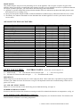
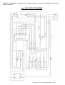
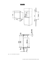
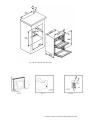
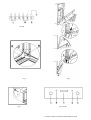
SINGLE 60S - DOUBLE 90D
BUILT-IN ELECTRIC OVEN
INSTALLATION,
USE AND CARE INSTRUCTIONS
1 9880015700 E OVEN RANGEMASTER 03-2006
INDEX
INSTALLATION INSTRUCTION GUIDE:
BUILT-IN OVEN TO CABINET UNIT
CHARACTERISTICS OF CABINET UNIT
OVEN ELECTRICAL CONNECTION
OVEN CLEANING
OVEN DOOR
REPLACING THE OVEN LIGHT
SPARE PARTS
APPLIANCE TECHNICAL FEATURES
page
3
3
3
4
4
4
5
5
OVEN USE GUIDE:
CONTROL PANEL
LIGHT INDICATORS
OVEN TEMPERATURE THERMOSTAT SWITCH
ELECTRONIC PROGRAMMER
MANUAL TIMER
OLD FASHION MANUAL TIMER
OVEN FUNCTION SELECTOR SWITCH
60S CIRCUIT DIAGRAM
90D CIRCUIT DIAGRAM
FIGURES
5
5
5
6
7
7
7–8
10
11
12 – 15
2 9880015700 E OVEN RANGEMASTER 03-2006
USE AND CARE INSTRUCTION
ATTENTION: FOR CORRECT INSTALLATION AND USE, YOU MUST REFER TO
YOUR OVEN MODEL TECHNICAL DATA. PLEASE, CHECK APPLIANCE
RATING PLATE FOR OVEN MODEL NUMBER.
INSTALLATION INSTRUCTION GUIDE
BUILT-IN OVEN TO CABINET UNIT:
The oven may be built-in either in a column or under countertop of a suitable cabinet unit.
Cut-out opening dimensions to be performed on cabinets are indicated in fig. 1. Make sure cabinet unit in which the
oven is to be fitted is sufficiently sturdy to take the weight of the appliance, approx. 35 Kg. for mod. 60S or 52 Kg.for
model 90D. Please follow respective oven model cut-out dimensions: Fig. 1A for mod. 60 S and Fig. 1B for mod. 90D.
On the bottom of the unit and/or on the shelf supporting the oven, remember to do the cut-out section at the back, see
fig. 1, to allow fresh air passage for appliance cooling.
Ensure that the oven is firmly fixed on provided cut-out. Use screws “A” , fig. 2, to secure oven.
CHARACTERISTICS OF CABINET UNIT: Cabinet Unit technical requirements as follow;
- The unit and its components must be able to resist a temperature of 90°C without becoming unglued or warped.
- The unit must allow free passage of the electrical connections as well as gas tubing in case is needed.
OVEN ELECTRICAL CONNECTION
IMPORTANT.
- This appliance must be connected to power supply only by a skilled authorised personal.
- Electrical connection must comply with requested local product electrical standard requirements.
- It must be powered by a single-phase 230V ~ 50Hz electrical connection;
EARTH OR GROUND CONNECTION IS MANDATORY.
- If electrical wiring is made directly to wall outlet, it is necessary to apply a breaker type of switch suitable to appliance
electrical power and standard requirements.
- IN ANY TIME, GROUND WIRING MUST NOT BE INTERRUPTED BY A SWITCH OR SIMILAR
COMPONENT.
THE APPLIANCE MUST ALWAYS BE DISCONNECTED FROM POWER SUPPLY BEFORE
PERFORMING ANY MAINTENANCE AND SETTINGS.
The appliances could be supplied with an electrical flexible cord without plug. In case of plug application, use a suitable
plug in accordance to the appliance technical specifications. Remember to properly connect the ground or yellow/green
wire to the plug’s ground lead
In case of flexible cord replacement or application, read following instruction:
- Disconnect electrical power supply.
- Open terminal block cover (for mod. 60S; fig. 3 - 4A and for mod. 90D; fig. 4B).
- Fix flexible cord leads properly as indicated in figure 4, Brown Hot (L), Neutral (N) and Ground. Remember the
yellow-green lead is ground. If a 13A (BS. 1363) plug is used, fit a 13 amp fuse.
- The flexible cord must always be secured by the cord clamp (fig. 4) on terminal block, so may not become loose by
being pulled accidentally. Also, make sure flexible cord does not touch hot point of over 75 °C through out the entire
cord length.
- Electrical plug must be suitable to appliance purpose, as mentioned before. Also, position the plug in a location
accessible after appliance installation, unless the appliance incorporates or is connected to a switch that ensures all-pole
disconnection. This type of switch must have a contact separation in all poles of not less than 3 mm.
ATTENTION: Use only electrical flexible cord with three-prong assembly, for all Single ovens use type
H05RR-FH 3 x 1.5 and for Twin-Style oven use type H05RR-FH 3 x 2.5.
3 9880015700 E OVEN RANGEMASTER 03-2006
OVEN CLEANING
CLEANING SAFETY
Turn off all controls and wait for appliance parts to cool before touching or cleaning them. Clean appliance with
caution. Use care to avoid steam burns if a wet sponge or clothe is used to wipe spills on a hot surface. Some cleaners
can produce noxious fumes if applied to a hot surface.
SURFACE CLEANING
This is easily done using a damp cloth and a non-abrasive detergent, wipe using a soft dry cloth. For stainless steel parts
with stubborn soils, use only plastic scrubbing pad or a sponge with vinegar and warm water. For Oven cooking cavity
cleaning, follow the same procedure mentioned above, but to ease the cleaning you may start cleaning when the cooking
cavity is still warm enough to be touched.
WARNING: Do not use steam cleaners to clean any part of the oven.
OVEN DOOR:
To remove and replace the Oven Door, please follow procedures here below;
REMOVING OVEN DOOR ON 60S MODELS: Fig. 5
Fully open the oven door. – Raise the U-clip over the hook on each of the hinges to the “locked” position, see figure 5
and 6. This will prevent the hinge from snapping closed when the door is removed. – Grasp the door by the sides toward
the back. – Raise the front of the door several centimetres (there will be some spring resistance to overcome because of
the hinge being locked). – When the front of the door is high enough, you will be able to lift the hinges to clear the
indents. – Pull the hinges out of the slots in the oven front frame.
TO REPLACE THE OVEN DOOR ON 60S MODELS: Fig. 5
Grasp the sides of the door at the centre and inert the ends of the hinges into the slots in the oven front frame as far as
they will go, see figure 5 and 6. – With the door open all the way, lower the two locking clips. – Raise the oven door
and make sure that it fits evenly with the front sides.
REMOVING OVEN DOOR ON 90D MODELS: Fig. 6
Open the door for about 45°. Step 1: With thumbs push levers “T” to bottom of the hinges. Step 2: Keeping levers “T”
down, lower the door till you hear the click when the “T” levers are locked and so blocking the hinges.
Step 3: Making sure “T” levers are locked, partially close the door to about 60°. Step 4: With the forefinger lift the “Z”
levers of both hinges. Step 5 and 6: Lift the door and take out as shown in fig. 6.
TO REPLACE THE OVEN DOOR ON 90D MODELS: Fig. 6
Grasp the door by the sides and insert hinges into their slots, keeping “Z” levers up (as in step 4). Hook the hinges into
their locations by following steps 6 and 5 backwards. Once “Z” levers are in place, fully the open door to unlock “T”
levers. Once “T” levers are in the up-right position, gently close the door.
WARNING. Never release the U-clip or T-clip levers when the door is off. Do not close the hinges without the weight
of the door, the powerful springs will snap the hinges closed with great force.
CAUTION: Do not place excessive weight on or stand on an open oven door. This could break the door or injure the
user. Also, do not attempt to open or close door or operate oven until door is properly replaced.
REPLACING THE OVEN LIGHT
WARNING; To prevent electrical shock and/or personal injury read follow this procedure:
Before replacing the light bulb, be sure the electric power is turned off at the circuit breaker.
Be sure the oven and light bulb are cool. Then remove light cover A by unscrewing it. Figure 7.
Do not touch hot bulb with a damp cloth as this may cause the bulb to break.
Replace light bulb with a 25 W for 230 V a.c. appliance bulb only. Figure 7.
If the light cover is damaged or broken, do not use the oven until a new cover is in place.
Do not operate the oven unless the light cover is securely in position.
4 9880015700 E OVEN RANGEMASTER 03-2006
SPARE PARTS.
Only authorised parts may be used in performing service on the appliance. Do not repair or replace any part of the
appliance unless specifically recommended in the manual. All other services should be referred to a qualified technician.
To request a product spare part, you must indicate the following product information:
1) Appliance or product model and serial production number which are indicated on product data label, placed on the
front-bottom of oven cooking cavity.
2) Spare part description and part number, technical information available only by authorised technical service centre.
3) And finally, also indicate information on the distributor that sold the appliance as well as your nearest technical
service centre.
APPLIANCE TECHNICAL FEATURES.
Voltage 230 V ~ 50 Hz
Total Power:
Top Heating Element:
Grill Heating Element:
Bottom Heating Element:
Centre Heating Element:
Oven Light:
Oven Fan:
Cooling Fan:
Useful Cooking Cavity Dimensions
Height
Width
Depth
Useful Volume
Grilling Surface Area
kW
kW
kW
kW
kW
W
W
W
MAIN (60S)
2.7
0.8
1.8
1.2
2.2
25
25
25
MAIN (90D)
2.7
0.8
2.6
1,5
2,2
25
25
25
TOP (90D)
2.7
mm
mm
mm
dm³
cm²
315
420
410
56
615
315
420
410
56
615
190
440
370
31
615
Power Consumption Performance
Power to reach 200° C
Power to maintain 200° C
Total Power Consumption
kW/h
kW/h
kW/h
0.46
0.54
1.00
0.46
0.54
1.00
0.26
0.53
0.79
OVEN USE GUIDES
CONTROL PANEL.
2.6
1.5
25
25
25
Please take a look at figure n° 8.
A = Selector knob - B = ON and OFF Power indicator light - C = Electronic Programmer
D = ON and OFF Thermostat indicator light - E = Thermostat knob control.
IMPORTANT:
When using the oven for the first time, let it work empty for about 1 hour at the most, if possible leaving the kitchen
windows open. When lit for the first time the oven gives off unpleasant smells due to manufacturing residue such as
grease, oil or resin.
ON AND OFF PILOT LIGHT
Whenever is on it means the oven is electrically powered and functioning, see figure 9.
TEMPERATURE PILOT LIGHT
It turns on and off to indicate the elements are turning on and off to maintain the desired oven temperature, see fig. 10.
OVEN TEMPERATURE THERMOSTAT SWITCH:
This control allows you to choose the desired Oven Cooking Temperature, for all function modes. The elements will
turn on and off to maintain oven cooking temperature.
5 9880015700 E OVEN RANGEMASTER 03-2006
ELECTRONIC PROGRAMMER, Fig. 11
The Clock:
You can use the timer to turn the ovens on and off. The clock must be set to the time of day before the ovens will work.
To set the time of day
or
Press as above. Then press (-) or (+) until the correct time shows. Once time has been set, wait 5 seconds to register the
new setting. Don’t forget it’s a 24 hour clock. If you make a mistake or press the wrong button, turn off the power
supply for three minutes and start again.
To time something that’s cooking (minute minder):
Press the
Minute Minder ( ).
Then after press the
(-) or (+) until the time you want
to cook for is shown.
You can check time remaining by pressing ( ) and cancel the beeper by pressing ( )
To stop automatically
Use when you have started the oven manually.
Press the Stop Time (
) button.
Then after press (-) or (+) until your required ‘Stop Time’ shows. “AUTO” will show in the display. When your
cooking is finished the beeper sounds. TURN THE OVEN KNOB TO 0 FIRST, then press ( ) once to stop the beep,
press ( ) again to return to manual cooking.
To start and stop the oven automatically. You must first set required Oven Function and cooking Temperature.
Before you set the clock, you must have two numbers clearly in mind.
The ‘cook period’, which is the period of time you want the oven to cook.
The ‘stop time’, which is the time of day you want the oven to stop cooking.
You cannot set a start time directly - this is set automatically by setting the cooking period and stop time.
Press the
Cook Time ( ) button.
Then press the
(-) or (+) until your
required ‘cook period’ shows.
Press the Stop
Time (
) button.
Then press the
(-) or (+) until your
required ‘stop time’ shows.
AUTO will show in the display.
6 9880015700 E OVEN RANGEMASTER 03-2006
Set the oven to the required temperature. When your cooking is finished the beeper sounds. TURN THE OVEN KNOB
TO 0 FIRST, then press ( ) once to stop the beep, press ( ) again to return to manual cooking.
If you are out, don’t worry about the beeper going off, it stops after a while. When you return, TURN THE OVEN
KNOB TO 0 FIRST, and then press ( ) twice, to return to manual cooking.
AUTO is showing, you want to reset to manual cooking.
When cancelling an automatic setting, any cooking time already set must be returned to 0.00 before you can return to
manual, by pressing the ( ) button.
OVEN FUNCTION SELECTOR SWITCH: Please look at Figure 12.
This control allows you to choose the desired Oven function mode. The following illustration gives an overview of what
happens in the oven with each mode setting. It also explains which element heats up for each specific mode. The lower
and circular elements are concealed under the floor and behind back wall of the oven respectively. The elements will
turn on and off to maintain the oven temperature.
Oven mod. 90D has two Selector Switches, one for each oven. The following symbols identify the oven to be selected:
on mod. 90D:
Base Main Oven,
on mod. Classic 90D:
Top Main Oven,
Top Grill Oven.
Base Grill Oven.
OVEN LIGHT ;
This function operates the Oven light. Also the light remains on in all other functions.
GRILL ;
This function operates the full top heating element. This element is used for browning the food and can also be used at
the end of a normal cooking period to give extra browning to dishes or give a crisper finish to meat. Pre-heat this
function before cooking. The oven door must be kept opened and thermostat set at MAX whilst grilling is in
progress.
TOP HEAT ;
This function operates the external top heating element It’s a useful function for browning or finishing of pasta dishes,
vegetables in sauce, shepherds pie and lasagne, the item to be browned being already hot before switching to the top
element.
BASE HEAT ;
This function operates the base heating element only. It will crisp up your pizza or quiche base or finish off cooking the
base of a pastry case on a lower shelf. It is also a gentle heat, good for slow cooking of casseroles in the middle of the
oven or for plate warming.
CONVENTIONAL OVEN (TOP AND BASE HEAT) ;
This function combines the heat from the top and base elements. It is particularly suitable for roasting and baking
pastry, cakes and biscuits. Food cooked on the top shelf will brown and crisp faster than on the lower shelf, because the
heat is greater at the top of the oven than at the base, as in “Fan assisted oven” function. Similar items being cooked will
need to be swapped around for even cooking. This means that foods requiring different temperatures can be cooked
together, using the cooler zone in the lower half of the oven and hotter area to the top.
FAN ASSISTED OVEN ;
This function operates the fan, circulating air heated by the elements at the top and the base of the oven. The
combination of a fan and conventional cooking (top and base heat) makes this function ideal for cooking large items
that need thorough cooking, such as a large meat roast. It is also possible to bake on two shelves at one time, although
they will need to be swapped over during the cooking time, as the heat at the top of the oven is greater than at the base,
when using this function. This is a fast intensive form of cooking; keep an eye on the food cooking until you have
become accustomed to this function.
7 9880015700 E OVEN RANGEMASTER 03-2006
FAN ASSISTED BASE HEAT ;
This function operates the fan, circulating air heated by the base element. It is a gentle way of cooking using the base
element for slow cooking of casseroles in the middle of the oven or for plate warminig.
OVEN FAN ;
This function operates the fan and the heat element around it. An even heat is produced throughout the oven, allowing
you to cook large amounts quickly.
Fan oven cooking is particular suitable for baking on several shelves at one time and is a goo “all-around” function. It
may be necessary to reduce the temperature by approximately 10°C for recipes previously cooked in a conventional
oven.
If you wish to pre-heat the oven, wait until the indicator light has gone out before inserting the food.
DEFROST ;
This function operates the fan to circulate cold air only. No heat is applied. This enables small items such as desserts,
cream cakes and pieces of meat, fish and poultry to be defrosted.
Defrosting in this way speeds up the process and protects the food from flies. Pieces of meat, fish and poultry should be
placed on a rack, over a tray to catch any drips. Be sure to wash the rack and tray after defrosting.
Defrost with the oven door closed.
Large items, such as whole chickens and joints should not be defrosted in this way. We recommend this be carried out
in a refrigerator.
Ensure that dairy foods, meat and poultry are completely defrosted before cooking.
FAN GRILLING ;
This function operates the fan whilst the top element is on. It produces a more even, less fierce heat than a conventional
grill. The supplied pan can be used on an oven shelf, and is designed to allow air circulation. Thick pieces of meat or
fish are ideal for grilling in this way, as the circulated air reduces the fierceness of the heat from the grill. The oven door
must be kept opened and thermostat set at MAX whilst grilling is in progress. You will also find that the food needs to
be watched and turned less than for normal grilling. Pre-heat this function before cooking.
ATTENTION: during Grilling, accessible parts can get very hot. So, children must stay at a safe distance.
CAUTION: During use the appliance becomes hot. Care should be taken to avoid touching heating elements
inside the oven.
This product conforms to EU Directive 2002/96/EEC.
The Wheelie bin with an X symbol printed on the product means the product, at the end of working lifecycle, being to
be treated separately from other domestics wastes, it must be handed over to a special waste treatment centre suitable for
electric and / or electronic appliances. Or, on the other hand, give it to the Appliance Store where you are going to buy
a similar electrical equipment.
The user is responsible to hand over the used product, at the end of its lifecycle, to a suitable special waste treatment
centre. Not doing so, the user can be charged with a fine in accordance with the current Waste Treatment Legislation.
The use of an adequate method for treating waste electrical equipment for recycle, will easy product compatibility with
environment. So, reducing negative environmental effects, health problems and increasing product components recycle.
For more detailed information on Special Waste Treatment, please contact your local waste treatment centre, or the store
where the appliance was bought from
THE MANUFACTURER DECLINES ANY LEGAL AND WARRANTY RESPONSIBILITY FOR NOT
FOLLOWING INSTALLATION AND WIRING INSTRUCTION IN ACCORDANCE WITH ELECTRICAL
EUROPEAN STANDARDS AS WELL AS APPLIANCE USER MISUSE.
This appliance complies with the requirements of the EEC directives 87/308; 73/23; 93/68 and 89/336.
8 9880015700 E OVEN RANGEMASTER 03-2006
SERVICE – WARNING: Disconnect from electricity before servicing. Check appliance is safe when
you have finished.
mod. 60S CIRCUIT DIAGRAM
9 9880015700 E OVEN RANGEMASTER 03-2006
mod. 90D CIRCUIT DIAGRAM
10 9880015700 E OVEN RANGEMASTER 03-2006
Single phase
2 phase
Connect the mains cable to the correct terminals for your electrical supply type. Check that the links are correctly fitted
and that the terminal screws are tight. Secure the mains cable using the cable clamp.
Circuit diagram legend:
COMPONENT LEGEND:
A:
TERMINAL BLOCK
C:
SELECTOR SWITCH
T:
THERMOSTAT
LF: OVEN LIGHT
PE: ELECTRONIC PROGRAMMER
R : RED LIGHT – POWER
G : ORANGE LIGHT – THERMOSTAT
MVT: COOLING FAN
MV: OVEN FAN
RC: TOP HEATING ELEMENT
RV: CENTRE HEATING ELEMENT
RG: GRILL HEATING ELEMENT
RS: BASE HEATING ELEMENT
COLOUR LEGEND:
DD: BLACK
11:
BROWN
22:
RED
33:
ORANGE
44:
YELLOW
45:
GREEN – YELLOW
55:
GREEN
66:
PURPLE
77:
BLUE
88:
CYAN
90:
GREY
99:
WHITE
11 9880015700 E OVEN RANGEMASTER 03-2006
FIGURES
Fig. 1A for 60S BUILT-IN OVEN
12 9880015700 E OVEN RANGEMASTER 03-2006
Fig. 1B for 90D BUILT-IN OVEN
Fig. 2
Fig. 3
Fig. 4A
13 9880015700 E OVEN RANGEMASTER 03-2006
Fig. 4B
Fig. 5
Fig. 7
Fig. 6
Fig. 8 (60S)
14 9880015700 E OVEN RANGEMASTER 03-2006
Fig. 9
Fig. 8 (90D)
Fig. 10
Fig. 11
Fig. 12
15 9880015700 E OVEN RANGEMASTER 03-2006
16 9880015700 E OVEN RANGEMASTER 03-2006