1
Installation and Operation Manual
RIC-E3/ETH,
RIC-T3/ETH
10/100BT to E3/T3
Interface Converters
RIC-E3/ETH, RIC-T3/ETH
10/100BT to E3/T3 Interface Converters
Installation and Operation Manual
Notice
This manual contains information that is proprietary to RAD Data Communications Ltd. ("RAD"). No
part of this publication may be reproduced in any form whatsoever without prior written approval by
RAD Data Communications.
Right, title and interest, all information, copyrights, patents, know-how, trade secrets and other
intellectual property or other proprietary rights relating to this manual and to the
RIC-E3/ETH, RIC-T3/ETH and any software components contained therein are proprietary products of
RAD protected under international copyright law and shall be and remain solely with RAD.
RIC-E3/ETH, RIC-T3/ETH is a registered trademark of RAD. No right, license, or interest to such
trademark is granted hereunder, and you agree that no such right, license, or interest shall be asserted
by you with respect to such trademark.
You shall not copy, reverse compile or reverse assemble all or any portion of the Manual or the
RIC-E3/ETH, RIC-T3/ETH. You are prohibited from, and shall not, directly or indirectly, develop,
market, distribute, license, or sell any product that supports substantially similar functionality as the
RIC-E3/ETH, RIC-T3/ETH, based on or derived in any way from the RIC-E3/ETH, RIC-T3/ETH. Your
undertaking in this paragraph shall survive the termination of this Agreement.
This Agreement is effective upon your opening of the RIC-E3/ETH, RIC-T3/ETH package and shall
continue until terminated. RAD may terminate this Agreement upon the breach by you of any term
hereof. Upon such termination by RAD, you agree to return to RAD the RIC-E3/ETH, RIC-T3/ETH and
all copies and portions thereof.
For further information contact RAD at the address below or contact your local distributor.
International Headquarters
RAD Data Communications Ltd.
U.S. Headquarters
RAD Data Communications Inc.
24 Raoul Wallenberg St.
Tel Aviv 69719 Israel
Tel: 972-3-6458181
Fax: 972-3-6498250
E-mail: [email protected]
900 Corporate Drive
Mahwah, NJ 07430 USA
Tel: (201) 529-1100, Toll free: 1-800-444-7234
Fax: (201) 529-5777
E-mail: [email protected]
© 1991–2002 RAD Data Communications Ltd.
Publication No. 132-200-07/02
Limited Warranty
RAD warrants to DISTRIBUTOR that the hardware in the RIC-E3/ETH, RIC-T3/ETH to be delivered
hereunder shall be free of defects in material and workmanship under normal use and service for a
period of twelve (12) months following the date of shipment to DISTRIBUTOR.
If, during the warranty period, any component part of the equipment becomes defective by reason of
material or workmanship, and DISTRIBUTOR immediately notifies RAD of such defect, RAD shall have
the option to choose the appropriate corrective action: a) supply a replacement part, or b) request
return of equipment to its plant for repair, or c) perform necessary repair at the equipment's location.
In the event that RAD requests the return of equipment, each party shall pay one-way shipping costs.
RAD shall be released from all obligations under its warranty in the event that the equipment has been
subjected to misuse, neglect, accident or improper installation, or if repairs or modifications were
made by persons other than RAD's own authorized service personnel, unless such repairs by others
were made with the written consent of RAD.
The above warranty is in lieu of all other warranties, expressed or implied. There are no warranties
which extend beyond the face hereof, including, but not limited to, warranties of merchantability and
fitness for a particular purpose, and in no event shall RAD be liable for consequential damages.
RAD shall not be liable to any person for any special or indirect damages, including, but not limited to,
lost profits from any cause whatsoever arising from or in any way connected with the manufacture,
sale, handling, repair, maintenance or use of the RIC-E3/ETH, RIC-T3/ETH, and in no event shall RAD's
liability exceed the purchase price of the RIC-E3/ETH, RIC-T3/ETH.
DISTRIBUTOR shall be responsible to its customers for any and all warranties which it makes relating
to RIC-E3/ETH, RIC-T3/ETH and for ensuring that replacements and other adjustments required in
connection with the said warranties are satisfactory.
Software components in the RIC-E3/ETH, RIC-T3/ETH are provided "as is" and without warranty of any
kind. RAD disclaims all warranties including the implied warranties of merchantability and fitness for a
particular purpose. RAD shall not be liable for any loss of use, interruption of business or indirect,
special, incidental or consequential damages of any kind. In spite of the above RAD shall do its best to
provide error-free software products and shall offer free Software updates during the warranty period
under this Agreement.
RAD's cumulative liability to you or any other party for any loss or damages resulting from any claims,
demands, or actions arising out of or relating to this Agreement and the RIC-E3/ETH, RIC-T3/ETH shall
not exceed the sum paid to RAD for the purchase of the RIC-E3/ETH, RIC-T3/ETH. In no event shall RAD
be liable for any indirect, incidental, consequential, special, or exemplary damages or lost profits, even if
RAD has been advised of the possibility of such damages.
This Agreement shall be construed and governed in accordance with the laws of the State of Israel.
Regulatory Information
FCC-15 User Information
This equipment has been tested and found to comply with the limits of the Class A digital device,
pursuant to Part 15 of the FCC rules. These limits are designed to provide reasonable protection
against harmful interference when the equipment is operated in a commercial environment. This
equipment generates, uses and can radiate radio frequency energy and, if not installed and used in
accordance with the instruction manual, may cause harmful interference to the radio communications.
Operation of this equipment in a residential area is likely to cause harmful interference in which case
the user will be required to correct the interference at his own expense.
Warning per EN 55022
This is a Class A product. In a domestic environment, this product may cause radio interference, in
which case the user may be required to take adequate measures.
Safety Information
Safety Warnings
Warning
The exclamation point within a triangle is intended to warn the operator or
service personnel of operation and maintenance factors relating to the
product and its operating environment which could pose a safety hazard.
Always observe standard safety precautions during installation, operation and maintenance of this
product. Only a qualified and authorized service personnel should carry out adjustment, maintenance
or repairs to this instrument. No adjustment, maintenance or repairs should be performed by either
the operator or the user.
Telecommunication Safety
The safety status of each of the ports on the RIC-E3/ETH, RIC-T3/ETH is declared according to
EN 41003 and is detailed in the table below:
Ports
Safety Status
Electrical E3/T3, Ethernet
SELV
Circuit operating with Safety Extra-Low Voltage
Declaration of Conformity
Manufacturer's Name:
RAD Data Communications Ltd.
Manufacturer's Address:
24 Raoul Wallenberg St.
Tel Aviv 69719
Israel
declares that the products:
RIC-E3/ETH, RIC-T3/ETH
Product Name:
Conform to the following standard(s) or other normative document(s):
EMC:
Safety:
EN 55022 (1994)
Limits and methods of measurement of radio disturbance
characteristics of information technology equipment.
EN 55024 (1998)
Electromagnetic compatibility – Generic immunity standards
for residential, commercial and light industry.
EN 60950/A4 (1996)
Safety of information technology equipment, including
electrical business equipment.
Supplementary Information:
The products herewith comply with the requirements of the EMC Directive 89/336/EEC and the Low
Voltage Directive 73/23/EEC. The products were tested in a typical configuration.
Tel Aviv, April 3rd, 2001
Haim Karshen
VP Quality
European Contact: RAD Data Communications GmbH, Otto-Hahn-Str. 28-30, 85521 Ottobrunn-Riemerling,
Germany
Quick Start Guide
If you are familiar with RIC-E3/ETH and RIC-T3/ETH interface converters, use this
guide to prepare the units for operation.
1.
Installing RIC-E3/ETH and RIC-T3/ETH
Open the RIC-E3/ETH or RIC-T3/ETH case by releasing the two rear panel screws
and sliding out the PCB interior of the unit.
Setting the Internal Jumpers
Setting the Main Board Jumpers
Set the main board jumpers according to the following table:
Jumper
Description
Values
TIMING, JP1
Selects the clock source
LBT – Receive clock
AIS, JP2
Controls the AIS
transmission
Factory Setting
INT – Internal clock
INT
ON – AIS is transmitted
ON
OFF – AIS is not transmitted
Selecting the E3/T3 Cable Length
Refer to the tables below and select the cable length, depending on your unit's
interface type: E3 or T3.
Jumper
Description
Values
Factory Setting
E3 Cable Length
Jumper, JP2
Selects the E3
cable length
Pins 1, 2 – Cable length is from 0 to 300 ft
Pins 1, 2
Pins 2, 3 – Cable length is more than 300 ft
Note: The maximum cable length complies with ITU-T G.703.
T3 Cable Length
Jumper Positions
JP1
JP2
JP3
0 ft – 225 ft
Pins 2, 3*
Pins 1, 2*
Pins 2, 3*
225 ft – 450 ft
Pins 1, 2
Pins 1, 2
Pins 1, 2
More than 450 ft
Pins 1, 2
Pins 2, 3
Pins 1, 2
Note: The maximum cable length complies with ITU-T G.703.
* – Factory settings
Installing RIC-E3/ETH and RIC-T3/ETH
1
RIC-E3/ETH, RIC-T3/ETH Installation and Operation Manual
Quick Start Guide
Configuring the Ethernet Interface
Configure the Ethernet interface according to the tables below:
Section
Name
1
NC
2
FLC
3
Description
Possible Settings
OFF
10/100
Enables or disables flow
control
ON – Flow control is enabled
Selects the LAN speed
ON – LAN speed is 100 Mbps
OFF – Flow control is disabled
OFF – LAN speed is 10 Mbps
4
5
AN1
HF1
Controls the LAN
autonegotiation
ON – LAN autonegotiation is disabled
Selects the LAN mode
ON – LAN full duplex mode
BPR
Controls the backpressure
MUL
Controls LAN to WAN
multicasting
SCR
Controls the scrambling of
Ethernet frames
OFF
OFF
ON – Multicast messages from LAN to
WAN are blocked
OFF – Multicast messages from LAN
to WAN are not blocked
8
OFF
ON – Backpressure is enabled
OFF – Backpressure is disabled
7
OFF
OFF – LAN autonegotiation is enabled OFF
OFF – LAN half duplex mode
6
Factory Setting
ON – Ethernet frames are scrambled
OFF – Ethernet frames are left
unchanged
OFF
OFF
Connecting the Cables
To connect cables:
1. Connect the E3 or T3 electrical interface.
2. Connect the Ethernet interface to the LAN.
3. Connect the power cable (first to the converter, then to the mains supply).
2.
Operating RIC-E3/ETH and RIC-T3/ETH
Verify LED status:
• The PWR LED should be ON.
2
•
The LINK and ACT LEDs should be ON, when the link to the LAN is
established, and data is transferred over the Ethernet link.
•
The ETH 100 LED is ON when the converters work in the 100 Mbps mode.
Operating RIC-E3/ETH and RIC-T3/ETH
Contents
Chapter 1. Introduction
1.1 Overview .......................................................................................................... 1-1
Versions...................................................................................................................1-1
Applications.............................................................................................................1-1
Features...................................................................................................................1-2
1.2 Physical Description .......................................................................................... 1-3
1.3 Functional Description ...................................................................................... 1-4
E3 Interface .............................................................................................................1-4
T3 Interface .............................................................................................................1-4
Ethernet Interface ....................................................................................................1-5
Timing .....................................................................................................................1-5
Alarm Relay .............................................................................................................1-5
1.4 Technical Specifications .................................................................................... 1-5
Chapter 2. Installation and Setup
2.1 Site Requirements and Prerequisites.................................................................. 2-1
2.2 Package Contents.............................................................................................. 2-1
2.3 Installation and Setup........................................................................................ 2-2
Setting the Internal Jumpers .....................................................................................2-2
Connecting the Interfaces ........................................................................................2-6
Connecting the Power .............................................................................................2-7
Chapter 3. Operation
3.1 Front Panel Indicators and Controls................................................................... 3-1
3.2 Operating Instructions ....................................................................................... 3-2
Turning On..............................................................................................................3-2
Normal Operating Instructions .................................................................................3-2
Turning Off..............................................................................................................3-2
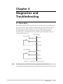
Chapter 4. Diagnostics and Troubleshooting
4.1 Alarm Relay ...................................................................................................... 4-1
4.2 Troubleshooting Instructions ............................................................................. 4-2
RIC-E3/ETH, RIC-T3/ETH Installation and Operation Manual
i
Table of Contents
List of Figures
1-1.
1-2.
1-3.
1-4.
1-5.
Logical Connection of Distant LANs........................................................................... 1-1
Connecting LAN to E3/T3 Service over Wireless Link................................................. 1-1
Cost-effective Connection to ISP................................................................................ 1-2
RIC-E3/ETH and RIC-T3/ETH, 3-D View .................................................................... 1-3
RIC-E3/ETH and RIC-T3/ETH Functional Diagram ..................................................... 1-4
2-1.
2-2.
2-3.
2-4.
2-5.
Main Board Layout.................................................................................................... 2-3
E3 Interface Board Layout ......................................................................................... 2-4
T3 Interface Board Layout ......................................................................................... 2-4
Ethernet Interface Board Layout ................................................................................ 2-5
RIC-E3/ETH Rear Panel ............................................................................................. 2-6
3-1. RIC-E3/ETH Front Panel ............................................................................................ 3-1
4-1. Alarm Relay Connector Pinout................................................................................... 4-1
List of Tables
2-1.
2-2.
2-3.
2-4.
2-5.
Main Board Jumper Settings ...................................................................................... 2-4
Selecting the E3 Interface Cable ................................................................................ 2-4
Selecting the T3 Interface Cable ................................................................................ 2-5
Ethernet Interface DIP Switch Settings ....................................................................... 2-5
RJ-45 Connector Pinout............................................................................................. 2-7
3-1. RIC-E3/ETH and RIC-T3/ETH Controls and Indicators ................................................ 3-1
4-1. Troubleshooting Chart ............................................................................................... 4-2
ii
RIC-E3/ETH, RIC-T3/ETH Installation and Operation Manual
Chapter 1
Introduction
1.1 Overview
RIC-E3/ETH and RIC-T3/ETH are interface converters, which convert between
unframed E3/T3 data and 10/100BaseT Ethernet. RIC-E3/ETH and RIC-T3/ETH
offer simple and cost-effective interconnection between 10/100BaseT LANs and
E3/T3 services, making distant LANs operate as one local network.
Versions
Two converter models are available:
•
RIC-E3/ETH: E3 to 10/100BaseT converter
•
RIC-T3/ETH: T3 to 10/100BaseT converter.
Power Options
•
AC power supply: 100 to 240 VAC
•
DC power supply: -48 VDC.
Applications
RIC-E3/ETH and RIC-T3/ETH provide logical connection of the distant LANs, as
shown in Figure 1-1.
Site A
Site B
E3/T3
RIC-E3/ETH or
RIC-T3/ETH
SDH
E3/T3
RIC-E3/ETH or
RIC-T3/ETH
Figure 1-1. Logical Connection of Distant LANs
Site A
Site B
SDH
RIC-E3/ETH or
RIC-T3/ETH
E3/T3
E3/T3
RIC-E3/ETH or
RIC-T3/ETH
Figure 1-2. Connecting LAN to E3/T3 Service over Wireless Link
Overview
1-1
RIC-E3/ETH, RIC-T3/ETH Installation and Operation Manual
Chapter 1 Introduction
Figure 1-3 shows RIC-E3/ETH and RIC-T3/ETH providing a cost-effective link to the
Internet Service Provider (ISP) by using a low-cost or existing 10/100BT connection
instead of expensive E3/T3 router interface.
Central Office/POP
10/100BT
ISP
E3/T3
E3/T3
SDH/SONET
Router
RIC-E3/ETH or
RIC-T3/ETH
RIC-E3/ETH or
RIC-T3/ETH
Figure 1-3. Cost-effective Connection to ISP
Features
RIC-E3/ETH and RIC-T3/ETH transparently connect an unframed E3 or T3 link
with a 10/100BaseT Ethernet system, utilizing the full E3/T3 bandwidth without the
heavy overhead associated with packet or cell-based technologies.
E3/T3 Interface
The E3 coax interface uses HDB3 line coding and fully complies with the
applicable ITU-T standards. The E3 interface terminates in two shielded
unbalanced BNC connectors.
The T3 coax interface uses B3ZS line coding and fully complies with the
requirements of ITU-T G.703 and G.824 standards. The T3 interface terminates in
two shielded unbalanced BNC connectors.
Ethernet Interface
The Ethernet interface of the RIC-E3/ETH and RIC-T3/ETH converters is a high
performance self-learning Ethernet bridge module, fully compatible with
IEEE 802.3/Ethernet V.2 standards.
Ethernet interface provides one LAN connection, which can be either 10BaseT
(UTP) or 100BaseT (UTP), both with VLAN tagging support.
The LAN link operates at a data rate of up to 10 Mbps for 10BaseT ports or up to
100 Mbps for 100BaseT ports.
Auto-negotiation allows plug-and-play Ethernet connection.
The Ethernet module is configured via an internal DIP switch.
1-2
Overview
RIC-E3/ETH, RIC-T3/ETH Installation and Operation Manual
Chapter 1 Introduction
1.2 Physical Description
Figure 1-4 illustrates a 3-D view of the RIC-E3/ETH and RIC-T3/ETH units.
Figure 1-4. RIC-E3/ETH and RIC-T3/ETH, 3-D View
The RIC-E3/ETH and RIC-T3/ETH front panel contains LEDs for indication of the
E3/T3 and Ethernet interface status. For details, refer to Chapter 3.
The rear panel of the unit allows access to the interface, alarm relay and power
connections. The rear panel is described in greater detail in Chapter 2.
Physical Description
1-3
RIC-E3/ETH, RIC-T3/ETH Installation and Operation Manual
Chapter 1 Introduction
1.3 Functional Description
Figure 1-4 illustrates the RIC-E3/ETH and RIC-T3/ETH functional diagram.
E3/T3 Interface
Ethernet Interface
TNRZ
Rx
Tx
TCLK
RNRZ
Tx
Rx
RCLK
Receive Clock
Internal Clock
Oscillator
Mux
Figure 1-5. RIC-E3/ETH and RIC-T3/ETH Functional Diagram
E3 Interface
The E3 interface includes a line interface transceiver, which utilizes HDB3
encoding and decoding. The E3 interface operates at the 34.368 Mbps data rate.
The line transceiver recovers clock and data from the incoming signals. The E3
cable length is user-selectable, and complies with ITU-T G.703 standards. The
connectors are two shielded BNC connectors with 75Ω impedance.
T3 Interface
The T3 interface includes a line interface transceiver, which utilizes B3ZS encoding
and decoding. The E3 interface operates at the 44.736 Mbps data rate. The line
transceiver recovers clock and data from the incoming signals. The T3 cable length
is user-selectable, and complies with ITU-T G.703 standards. The connectors are
two shielded BNC connectors with 75Ω impedance.
1-4
Functional Description
RIC-E3/ETH, RIC-T3/ETH Installation and Operation Manual
Chapter 1 Introduction
Ethernet Interface
The Ethernet interface includes a high performance self-learning Ethernet bridge,
which is connected to the LAN via a single 10BaseT or 100BaseT port, operating in
half or full duplex.
The module automatically learns MAC addresses of the LAN to which it is
connected. Its LAN table stores up to 1,000 addresses with 5-minute automatic
aging.
Filtering and forwarding is performed at the maximum theoretical rate of 150,000
frames per second (wire speed). The bridge has an internal buffer for frames that is
16Kx32 (64 KB). The forwarding of the broadcast and multicast messages from
LAN to WAN can be disabled.
Timing
Figure 1-5 shows flow of the clock signals in the RIC-E3/ETH and RIC-T3/ETH unit.
Two timing modes are supported:
•
Receive clock: the system timing is locked to the recovered receive clock
signal coming from E3/T3 interface.
•
Internal clock: an onboard crystal oscillator (±25 ppm) serves as the timing
source for the system.
Alarm Relay
RIC-E3/ETH and RIC-T3/ETH feature an alarm port, used for the relay of the alarm
conditions (AIS and LOW) by means of Normally Open and Normally Closed dry
contacts, using different pins of the DB-9 port connector.
1.4 Technical Specifications
E3/T3
Interface
Transmission Rate
• E3: 34.368 Mbps
• T3: 44.736 Mbps
Line Code
• E3: HDB3
• T3: B3ZS
Ethernet
Interface
Impedance
75Ω, unbalanced
Connectors
Two shielded BNC (unbalanced)
LAN Table
1,000 MAC addresses
Aging
5 minute, automatic
Filtering and
Forwarding Rate
150,000 frames per second
Buffer Size
170 frames
Technical Specifications
1-5
RIC-E3/ETH, RIC-T3/ETH Installation and Operation Manual
Chapter 1 Introduction
Delay
1 frame
LAN Standard
IEEE 802.3/Ethernet V.2
LAN Data Rate
• 10BaseT: 10 Mbps (20 Mbps in full duplex)
• 100BaseT: 100 Mbps (200 Mbps in full duplex)
Transmission Line
4-wire, Category 5 UTP, 19 AWG to 26 AWG
Line Code
• 10BaseT: Manchester
• 100BaseT: MLT3
Timing
WAN Protocol
Point-to-point
Connector
RJ-45
Clock Source
• Receive clock: recovered from the receive clock signal
coming from E3/T3 interface
• Internal clock: provided by onboard crystal oscillator
(±25 ppm)
Indicators
Alarm Relay
Power
Physical
PWR
ON – RIC-E3/ETH or RIC-T3/ETH is powered up
ELECTRICAL LOW
ON – E3/T3 input is below G.703 level
ELECTRICAL AIS
ON – E3/T3 interface received Alarm Indication Signal
ETH LINK
ON – LAN is connected to the Ethernet interface
ETH ACT
BLINKS – LAN is receiving/transmitting data
ETH 100
ON – LAN is operating at 100 Mbps
OFF – LAN is operating at 10 Mbps
Connector
9-pin, D-type female
Operation
Normally Open and Normally Closed, using different
pins
AC Source
100–240 VAC, 50 Hz–60 Hz, 15 VA
DC Source
-48 VDC, 9W
Height
4.4 cm / 1.7 in
Width
19.4 cm / 7.6 in
Depth
24.3 cm / 9.6 in
Weight
Environment
1-6
1.4 kg / 3.0 lb
Temperature
0 to 50°C (32 to 122°F)
Humidity
Up to 90%, non-condensing
Technical Specifications
Chapter 2
Installation and Setup
This chapter describes installation procedures for the standalone RIC-E3/ETH and
RIC-T3/ETH devices.
After installing the unit, refer to Chapter 3 for the system operation information.
Refer to Chapter 4 for troubleshooting and diagnostics information.
Internal settings, adjustment, maintenance, and repairs may be performed
only by a skilled technician who is aware of the hazards involved.
Warning Always observe standard safety precautions during installation, operation and
maintenance of this product.
2.1 Site Requirements and Prerequisites
AC-powered RIC-E3/ETH and RIC-T3/ETH units should be installed within 1.5m
(5 ft) of an easily-accessible grounded AC outlet capable of furnishing the required
supply voltage, in the range of 100 to 240 VAC.
DC-powered RIC-E3/ETH and RIC-T3/ETH units require a -48 VDC power source,
which must be adequately isolated from the mains supply. In order to prevent a
fire hazard, a suitable fuse must be installed in the -48 VDC line.
The maximum trunk current of the AC or DC supply must be limited to 16A.
Allow at least 90 cm (36 in) of frontal clearance for operator access and at least
10 cm (4 in) clearance at the rear of the unit for interface cable connections.
The ambient operating temperature of RIC-E3/ETH and RIC-T3/ETH should be
0 to 50°C (32 to 122°F), at a relative humidity of up to 90%, non-condensing.
2.2 Package Contents
The RIC-E3/ETH or RIC-T3/ETH package includes the following items:
•
RIC-E3/ETH or RIC-T3/ETH unit
•
Interface Converters and Sharing Devices CD
•
AC power cord or DC power supply connector kit
Package Contents
2-1
Chapter 2 Installation and Setup
RIC-E3/ETH, RIC-T3/ETH Installation and Operation Manual
2.3 Installation and Setup
RIC-E3/ETH and RIC-T3/ETH are a standalone devices intended for tabletop or
19-inch rack installation. They are delivered completely assembled. No provision is
made for bolting the unit on the tabletop.
To install RIC-E3/ETH or RIC-T3/ETH:
1. Determine the required configuration of RIC-E3/ETH or RIC-T3/ETH according
to your application, and set the internal jumpers and switches accordingly.
2. Connect the E3/T3 lines and the LAN.
3. Connect power to the unit.
Setting the Internal Jumpers
This section provides information on the functions of the RIC-E3/ETH and
RIC-T3/ETH jumpers, and gives step-by-step instructions for performing the
internal settings. The default settings are also listed.
Locations of Jumpers and Switches
RIC-E3/ETH and RIC-T3/ETH include three printed circuit boards (PCBs): the main
board, E3/T3 interface board, and Ethernet interface board (see Figure 2-1,
Figure 2-2, Figure 2-3 and Figure 2-4).
The main board contains the common signal processing circuits. Two jumpers, JP1
and JP2, are provided for user settings.
The E3/T3 interface boards provide connection to the E3/T3 links. The E3/T3
boards contain jumpers for selecting the E3/T3 cable length.
The Ethernet interface board provides LAN connection. The Ethernet board
contains an 8-section DIP switch for the interface configuration.
Opening the Case
To reach the internal jumpers and switch of RIC-E3/ETH and RIC-T3/ETH, it is
necessary to open its case.
Access to the inside of RIC-E3/ETH and RIC-T3/ETH is permitted only to
authorized and qualified service personnel.
To avoid accidental electric shock, always disconnect the interface cables and
Warning the power cord before removing the units from their casing.
Line voltages are present inside RIC-E3/ETH and RIC-T3/ETH when they are
connected to power and/or to the lines. Moreover, under external fault
conditions dangerous voltages may appear on the lines connected to the units.
Any adjustment, maintenance, and repair of the opened equipment under
voltage should be avoided as much as possible and, when absolutely
necessary, should be carried out only by a skilled technician who is aware of
the hazard involved. Capacitors inside the instruments may still be charged
even after the instruments have been disconnected from their power source.
2-2
Installation and Setup
RIC-E3/ETH, RIC-T3/ETH Installation and Operation Manual
Chapter 2 Installation and Setup
Caution RIC-E3/ETH and RIC-T3/ETH contain components sensitive to electrostatic
discharge (ESD). To prevent ESD damage, avoid touching the internal components.
Before moving jumpers, touch the RIC-E3/ETH or RIC-T3/ETH frame.
To open the RIC-E3/ETH or RIC-T3/ETH case:
1. Disconnect all the cables connected to RIC-E3/ETH or RIC-T3/ETH.
2. Release the two rear panel screws and use them as levers to slide out the PCB
interior of the unit.
Setting the Main Board Internal Jumpers
The internal jumpers located on the RIC-E3/ETH or RIC-T3/ETH main board are
identified in Figure 2-1. The jumper settings are described in Table 2-1.
Ethernet
Interface Board
E3 or T3 Interface Board
TIMING
JP1
LBT
INT
AIS
JP2
OFF
ON
Figure 2-1. Main Board Layout
Installation and Setup
2-3
RIC-E3/ETH, RIC-T3/ETH Installation and Operation Manual
Chapter 2 Installation and Setup
Table 2-1. Main Board Jumper Settings
Jumper
Description
Values
TIMING, JP1
Selects the clock source
LBT – Receive clock
AIS, JP2
Controls the AIS
transmission
Factory Setting
INT – Internal clock
INT
ON – AIS is transmitted
ON
OFF – AIS is not transmitted
Setting the E3/T3 Interface Board Jumpers
The JP2 jumper, which is used for selection of the E3 cable length is located on the
E3 interface board of RIC-E3/ETH (see Figure 2-2 and Table 2-2).
JP2
1
2
3
Figure 2-2. E3 Interface Board Layout
Table 2-2. Selecting the E3 Interface Cable
Jumper
Description
Values
Factory Setting
E3 Cable
Length Jumper,
JP2
Selects the E3
cable length
Pins 1, 2 – Cable length is from 0 to 300 ft
Pins 1, 2
Pins 2, 3 – Cable length is more than 300 ft
Note: The maximum cable length complies with ITU-T G.703.
The JP1, JP2 and JP3jumpers, which are used for selection of the T3 cable length
are located on the T3 interface board (see Figure 2-3 and Table 2-3).
JP2
JP3
1
2
3
JP1
Figure 2-3. T3 Interface Board Layout
2-4
Installation and Setup
RIC-E3/ETH, RIC-T3/ETH Installation and Operation Manual
Chapter 2 Installation and Setup
Table 2-3. Selecting the T3 Interface Cable
T3 Cable Length
Jumper Positions
JP1
JP2
JP3
0 ft – 225 ft
Pins 2, 3*
Pins 1, 2*
Pins 2, 3*
225 ft – 450 ft
Pins 1, 2
Pins 1, 2
Pins 1, 2
More than 450 ft
Pins 1, 2
Pins 2, 3
Pins 1, 2
Note: The maximum cable length complies with ITU-T G.703.
* – Factory settings
Setting the Ethernet Interface Board Switch
The Ethernet interface board of RIC-E3/ETH and RIC-T3/ETH contains a DIP
switch, which is used for the bridge and LAN interface configuration
(see Figure 2-4 and Table 2-4).
87 6 5 4 3 2 1
S1
ON
Figure 2-4. Ethernet Interface Board Layout
Table 2-4. Ethernet Interface DIP Switch Settings
Section
Name
1
NC
2
FLC
3
10/100
Description
Possible Settings
Factory Setting
OFF
Enables or disables flow
control
ON – Flow control is enabled
Selects the LAN speed
ON – LAN speed is set to 100 Mbps
OFF – Flow control is disabled
OFF – LAN speed is set to 10 Mbps
4
5
AN1
HF1
Controls the LAN
autonegotiation
ON – LAN autonegotiation is disabled
Selects the LAN mode
ON – LAN full duplex mode
OFF – LAN autonegotiation is enabled
OFF – LAN half duplex mode
6
BPR
Controls the backpressure
OFF
OFF
OFF
OFF
ON – Backpressure is enabled
OFF – Backpressure is disabled
OFF
Installation and Setup
2-5
RIC-E3/ETH, RIC-T3/ETH Installation and Operation Manual
Chapter 2 Installation and Setup
Table 2-4. Ethernet Interface DIP Switch Settings (Cont.)
Section
Name
Description
Possible Settings
Factory Setting
7
MUL
Controls LAN to WAN
multicasting
ON – Multicast messages from LAN to
WAN are blocked
OFF – Multicast messages from LAN to OFF
WAN are not blocked
8
SCR
Controls the scrambling of ON – Ethernet frames are scrambled
Ethernet frames
OFF – Ethernet frames are left
unchanged
OFF
Closing the Case
Once you finish the internal settings, you have to close the RIC-E3/ETH and
RIC-T3/ETH case.
To close the RIC-E3/ETH or RIC-T3/ETH case:
1. Slide the unit's interior back into the case.
2. Screw in the two rear panel screws to fasten the main board in the case.
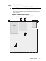
Connecting the Interfaces
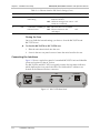
Figure 2-5 shows a typical rear panel of a standard RIC-E3/ETH unit and identifies
connector locations for the AC version.
The RIC-E3/ETH and RIC-T3/ETH rear panels contain also LAN status indicators,
which duplicate the front panel LAN LEDs. The LINK and ACT indicators are
located on the Ethernet interface connector.
LINE
ALARMS
IN
OUT
100M
Figure 2-5. RIC-E3/ETH Rear Panel
2-6
Installation and Setup
10/100BASE-T
ACT
LINK
RIC-E3/ETH, RIC-T3/ETH Installation and Operation Manual
Chapter 2 Installation and Setup
Connecting the E3/T3 Interface
The E3/T3 interface of RIC-E3/ETH and RIC-T3/ETH terminates in two BNC coax
connectors, designated IN and OUT.
To connect E3/T3 interface:
1. Connect the receive line, using a 75Ω coaxial cable to the BNC connector
labeled IN.
2. Connect the transmit line, using a 75Ω coaxial cable to the BNC connector
labeled OUT.
Connecting the Ethernet Interface
The Ethernet interface of RIC-E3/ETH and RIC-T3/ETH terminates in an RJ-45
connector, designated 10/100BASE-T. Table 2-5 lists the RJ-45 connector pinout.
To connect the Ethernet interface:
•
Connect the LAN to the RIC-E3/ETH or RIC-E3/ETH port, labeled
10/100BASE-T.
Table 2-5. RJ-45 Connector Pinout
Pin
Name
Function
1
RD (+)
Receive Data Positive
2
RD (-)
Receive Data Negative
3
TD (+)
Transmit Data Positive
6
TD (-)
Transmit Data Negative
Connecting the Power
To connect RIC-E3/ETH or RIC-E3/ETH to the power source, refer to the
appropriate section below, depending on your version of the unit (AC or DC).
The units have no power switch. Operation starts when the power is applied to
the rear panel POWER connector.
Before switching on this unit and connecting or disconnecting any other cable,
Warning the protective earth terminals of this unit must be connected to the protective
ground conductor of the mains power cord. If you are using an extension cord
(power cable) make sure it is grounded as well.
Any interruption of the protective (grounding) conductor (inside or outside the
instrument) or disconnecting of the protective earth terminal can make this
unit dangerous. Intentional interruption is prohibited.
For the AC version, make sure that only fuses of the required rating, as marked
on the rear panel, are used for replacement. Do not use repaired fuses or
short-circuit the fuse holder. Always disconnect the mains cable before
removing or replacing the fuse. Whenever it is likely that the fuse protection
has been damaged, make the unit inoperative and secure it against unintended
operation.
Installation and Setup
2-7
Chapter 2 Installation and Setup
RIC-E3/ETH, RIC-T3/ETH Installation and Operation Manual
Connecting the AC Power
AC power should be supplied to RIC-E3/ETH and RIC-E3/ETH through the 1.5m
(5 ft) standard power cable terminated by a standard 3-prong plug (see Figure 2-5).
The cable is provided with the unit.
To connect AC power:
• Connect the power cable first to the connector on the RIC-E3/ETH or
RIC-E3/ETH rear panel, and then to the mains outlet.
RIC-E3/ETH and RIC-E3/ETH will be turned on automatically upon
connection to the mains.
Connecting the DC Power
To connect DC power:
• Refer to DC Power Supply Connection Supplement.
2-8
Installation and Setup
Chapter 3
Operation
This chapter describes the RIC-E3/ETH and RIC-T3/ETH controls and indicators,
and their functions, explains the units' operating procedures.
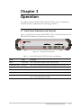
3.1 Front Panel Indicators and Controls
Figure 3-1 shows the front panel of RIC-E3/ETH. Table 3-1 lists the functions of the
RIC-E3/ETH LED indicators, located on the front panel.
LINE
LOW
PWR
ETH
AIS
LINK
ACT
100
Figure 3-1. RIC-E3/ETH Front Panel
Table 3-1. RIC-E3/ETH and RIC-T3/ETH Controls and Indicators
Name
Type
Function
PWR
Green LED
ON – RIC-E3/ETH and RIC-T3/ETH is powered up
ELECTRICAL LOW
Red LED
ON – E3/T3 input signal is below the minimum level required (G.703)
ELECTRICAL AIS
Yellow LED
ON – E3/T3 interface received "All 1s" string
ETH LINK
Green LED
ON – LAN is connected to the Ethernet interface
ETH ACT
Yellow LED
ON – LAN is receiving/transmitting data
ETH 100
Green LED
ON – LAN is operating at 100 Mbps
OFF – LAN is operating at 10 Mbps
Front Panel Indicators and Controls
3-1
RIC-E3/ETH, RIC-T3/ETH Installation and Operation Manual
Chapter 3 Operation
3.2 Operating Instructions
Turning On
RIC-E3/ETH and RIC-T3/ETH start operating as soon as they are connected to the
power source. The PWR LED turns ON and remains lit as long as the units are
connected to the mains.
Normal Operating Instructions
The following LEDs conditions are observed during the normal operation:
•
PWR is ON.
•
LINK and ACT are ON to indicate data transfer over the Ethernet link.
•
ETH 100 turns ON when RIC-E3/ETH and RIC-T3/ETH operate in Fast
Ethernet (100 Mbps) mode.
The rest of the front panel LEDs are OFF.
Turning Off
Turn RIC-E3/ETH and RIC-T3/ETH off by disconnecting the power cord from the
mains.
3-2
Operating Instructions
Chapter 4
Diagnostics and
Troubleshooting
4.1 Alarm Relay
RIC-E3/ETH and RIC-T3/ETH include a dry contact alarm relay port supported via
9-pin connector for major and minor alarms. Major alarms are defined as E3/T3
electrical low levels. Minor alarms occur when an Alarm Indication Signal is
received at the E3/T3 electrical interface. The dry contact port operates as
Normally Open or Normally Closed, using different pins of the alarm relay port
connector (see Figure 4-1).
Alarm Connector
Minor Alarm Relay
1
2
6
Major Alarm Relay
4
5
9
Minor-NO
Minor-NC
Minor-COM
Major-NO
Major-NC
Major-COM
Figure 4-1. Alarm Relay Connector Pinout
Note
The relay positions are shown in the non-energized state (alarm active).
Alarm Relay
4-1
Chapter 4 Diagnostics and Troubleshooting
RIC-E3/ETH, RIC-T3/ETH Installation and Operation Manual
4.2 Troubleshooting Instructions
In case a problem occurs, refer to Table 4-1 for the troubleshooting procedures.
Perform the actions listed under Corrective Measures in the order given in the
table, until the problem is corrected.
Table 4-1. Troubleshooting Chart
Trouble Symptoms
Probable Cause
Corrective Measures
PWR indicator is OFF
No AC power
• Verify that the power outlet is providing the
required power.
• Ensure that the both ends of the power cable are
connected properly.
ELECTRICAL LOW
indicator is ON
ELECTRICAL AIS
indicator is ON
4-2
Blown fuse
Replace with a fuse of correct rating
One of the E3/T3 coaxial
cables is defective or
disconnected
Ensure that both ends of the E3/T3 coaxial cables are
connected correctly and that the cables function
properly.
Attached equipment
outputs do no comply
with G.703 electrical
levels
Check that the output levels of the equipment
attached to the E3/T3 interface comply with G.703.
JP2 is set incorrectly
Correct the JP2 settings according to Table 2-1.
Attached equipment
transmits "All 1s" string
Check the equipment attached to E3/T3 interface,
ensure that it transmits real data.
Troubleshooting Instructions
DC Power Supply Connection – Terminal Block Connector
Note: Ignore this supplement if the unit is AC-powered.
Certain DC-powered units are equipped with a plastic 3-pin VDC-IN power input connector, located on the unit
rear panel. Supplied with such a unit, is a mating Terminal Block (TB) type connector plug for attaching to your
power supply cable.
Connect the wires of your power supply cable to the TB plug, according to the voltage polarity and assembly
instructions provided below.
Caution: Prepare all connections to the TB plug
before inserting it into the unit’s VDC-IN connector.
DC Power Input
Connector
20 mm
(on unit panel)
Wire stripping
dimensions
5 mm
Preparing and Connecting the TB Plug
Refer to Figure 1 for assistance.
Terminal screws
1. Strip the insulation of your power supply
wires according to the dimensions shown.
2. Place each wire lead into the appropriate TB
plug terminal according to the voltage
polarity mapping shown in Figure 2. (If a
terminal is not already open, loosen its
screw). Afterwards, tighten close the three
terminal screws.
Nylon cable tie
See Figure 2
for mapping
3. Pull a nylon cable tie (supplied) around the
power supply cable to secure it firmly to the
TB plug grip (pass the tie through the holes
on the grip).
Mating
TB Connector
Plug
DC power
cable
TB plug grip
Figure 1
4. Isolate the exposed terminal screws/wire leads using a plastic
sleeve or insulating tape, to prevent the possibility of short-circuit.
TB Connector
Plug
5. Connect the assembled power supply cable to the unit by
inserting the TB plug into the unit’s VDC-IN connector until it
snaps into place.
0
DC Power Supply Wire Voltage Polarity
Refer to Figure 2 for proper mapping of the power supply wire leads
to the TB plug’s three terminals.
Chassis (frame)
Ground
+
Positive pole
Warning:
• Reversing the wire voltage polarity can cause damage to the unit!
• Always connect a ground (earth) wire to the TB plug’s Chassis
(frame) Ground terminal. Connecting the unit without a protective
ground, or interruption of the grounding (for example, by using an
extension power cord without a grounding conductor) can cause
harm to the unit or to the equipment connected to it!
-48
or
(-24
)
24/48VDC Negative pole
Figure 2
SUP-220-01/02
24 Raoul Wallenberg St., Tel Aviv 69719, Israel
Tel: +972-3-6458181, Fax: +972-3-6483331, +972-3-6498250
E-mail: [email protected], Web site: http://www.rad.com
Customer Response Form
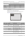
RAD Data Communications would like your help in improving its product documentation.
Please complete and return this form by mail or by fax or send us an e-mail with your
comments.
Thank you for your assistance!
Manual Name: ______________________________________________________________
Publication Number: __________________________________________________________
Please grade the manual according to the following factors:
Installation instructions
Operating instructions
Manual organization
Illustrations
The manual as a whole
Excellent
Good
Fair
Poor
Very Poor
❒
❒
❒
❒
❒
❒
❒
❒
❒
❒
❒
❒
❒
❒
❒
❒
❒
❒
❒
❒
❒
❒
❒
❒
❒
What did you like about the manual?
___________________________________________________________________________
___________________________________________________________________________
___________________________________________________________________________
___________________________________________________________________________
___________________________________________________________________________
1
Error Report
Type of Error(s)
❒
Incompatibility with product
or Problem(s):
❒
Difficulty in understanding text
❒
Regulatory information (Safety, Compliance, Warnings, etc.)
❒
Difficulty in finding needed information
❒
Missing information
❒
Illogical flow of information
❒
Style (spelling, grammar, references, etc.)
❒
Appearance
❒
Other _________
Please list the exact page numbers with the error(s), detail the errors you found (information missing,
unclear or inadequately explained, etc.) and attach the page to your fax, if necessary.
_________________________________________________________________________________________
_________________________________________________________________________________________
_________________________________________________________________________________________
_________________________________________________________________________________________
Please add any comments or suggestions you may have.
_________________________________________________________________________________________
_________________________________________________________________________________________
_________________________________________________________________________________________
You are:
❒
Distributor
❒
End user
❒
VAR
❒
Other ________________________
Who is your distributor?
_______________________________
Your name and company: ___________________________________________________________
Job title: __________________________________________________________________________
Address: __________________________________________________________________________
Direct telephone number and extension: _______________________________________________
Fax number: ______________________________________________________________________
E-mail: _____________________________________________________________________
2
www.rad.com
INTERNATIONAL HEADQUARTERS:
24 Raoul Wallenberg Street, Tel Aviv 69719, Israel, Tel: 972-3-6458181
Fax: 972-3-6498250, 972-3-6474436, Email: [email protected]
U.S. HEADQUARTERS:
900 Corporate Drive, Mahwah, N.J. 07430, Tel: (201) 529-1100
Toll Free: 1-800-444-7234, Fax: (201) 529-5777, Email: [email protected]
Publication Number 132-200-07/02