1
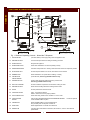
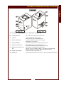
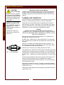
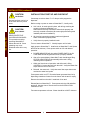
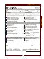
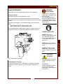
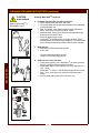
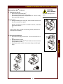
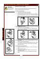
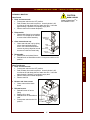
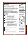
705
OWNERS MANUAL
WATER-MAX
WM-TR
Includes
INSTALLATION
USE & CARE
SERVICE
IMPORTANT: DO NOT DISCARD THIS MANUAL
This manual is considered to be part of the appliance and is to be given to the OWNER or
MANAGER of the restaurant, or to the person responsible for TRAINING OPERATORS of
this appliance. Additional manuals are available from your WELLS DEALER.
THIS MANUAL MUST BE READ AND UNDERSTOOD BY ALL PERSONS USING OR
INSTALLING THIS APPLIANCE. Contact your WELLS DEALER if you have any
questions concerning installation, operation or maintenance of this equipment.
p/n 305681 Rev. A
M705 012803 cps
LIMITED WARRANTY STATEMENT
GENERAL
This Water-Max™ hot water dispenser manufactured by
WELLS MFG. CO. is warranted against defects in materials
and workmanship for a period of two years from the date of
original installation and is for the benefit of the original
purchaser only.
THIS WARRANTY IS THE COMPLETE AND ONLY WARRANTY,
EXPRESSED OR IMPLIED IN LAW OR IN FACT, INCLUDING
BUT NOT LIMITED TO, WARRANTIES OF MERCHANTABILITY
OR FITNESS FOR ANY PARTICULAR PURPOSE, AND/OR FOR
DIRECT, INDIRECT OR CONSEQUENTIAL DAMAGES IN
CONNECTION WITH WELLS MFG. CO. PRODUCTS.
This warranty is void if it is determined that, upon inspection by
an authorized service agency, the equipment has been modified,
misused, misapplied, improperly installed, or damaged in
transit or by fire, flood or act of God. It also does not apply if
the serial nameplate has been removed, or if service is performed
by unauthorized personnel. The prices charged by Wells
Mfg. Co. for its products are based upon the limitations in
this warranty. Seller’s obligation under this warranty is limited to
the repair of defects without charge by a Wells Mfg. Co. factory
authorized service agency or one of its sub-service agencies. This
service will be provided on customer’s premises for nonportable models. Portable models (a device with a cord and
plug) must be taken or shipped to the closest authorized
service agency, transportation charges prepaid, for service.
In addition to restrictions contained in this warranty, specific
limitations are shown in the Service Policy and Procedure
Guide. Wells Mfg. Co. authorized service agencies are located in
principal cities. This warranty is valid in the United States
and Canada and void elsewhere. Please consult your classified
telephone directory, your foodservice equipment dealer or
write the Factory Service Department
Wells Manufacturing Company, P.O. Box 280
Verdi, Nevada, USA 89439
Phone: (775) 689-5700 or (888) 492-2782, for information
and other details concerning warranty.
SERVICE POLICY AND PROCEDURE GUIDE
ADDITIONAL WARRANTY EXCLUSIONS
1.
2.
3.
4.
5.
6.
Resetting of safety thermostats, circuit breakers, over
load protectors, and/or fuse replacements are not
covered by this warranty unless warranted conditions
are the cause.
All problems due to operation at voltages or phase
other than specified on equipment nameplates are
not covered by this warranty.
Conversion to correct voltage and/or phase must be
the customer’s responsibility.
All problems due to electrical connections not made
in accordance with electrical code requirements
and wiring diagrams supplied with the equipment are
not covered by this warranty.
Replacement of items subject to normal wear, to
include such items as knobs, light bulbs; and, normal
maintenance functions including adjustments of
thermostats, adjustment of micro switches and
replacement of fuses and indicating lights are not
covered by warranty.
Damage to electrical cords and/or plug due to exposure
to excessive heat are not covered by this warranty.
Full use, care, and maintenance instructions supplied
with each machine. Noted maintenance and
preventative maintenance items, such as servicing and
cleaning schedules, are customer responsibility. Those
miscellaneous adjustments noted are customer
responsibility. Proper attention to preventative
maintenance and scheduled maintenance procedures
will prolong the life of the appliance.
7. Travel mileage is limited to sixty (60) miles from an
Authorized Service Agency or one of its sub-service
agencies.
8. All labor shall be performed during regular working
hours. Overtime premium will be charged to the buyer.
9. All genuine Wells replacement parts are warranted for
ninety (90) days from date of purchase on nonwarranty equipment. This parts warranty is limited only
to replacement of the defective part(s). Any use of
non-genuine Wells parts completely voids any
warranty.
10. Installation, labor, and job check-outs are not
considered warranty and are thus not covered by this
warranty.
11. Charges incurred by delays, waiting time or operating
restrictions that hinder the service technician’s ability to
perform service are not covered by warranty. This
includes institutional and correctional facilities.
SHIPPING DAMAGE CLAIM PROCEDURE
NOTE: For your protection, please note that equipment in
this shipment was carefully inspected and packaged
by skilled personnel before leaving the factory. Upon
acceptance of this shipment, the transportation company
assumes full responsibility for its safe delivery.
IF SHIPMENT ARRIVES DAMAGED:
1. VISIBLE LOSS OR DAMAGE: Be certain that any
visible loss or damage is noted on the freight bill or
express receipt, and that the note of loss or damage is
signed by the delivery person.
2. FILE CLAIM FOR DAMAGE IMMEDIATELY:
Regardless of the extent of the damage.
3.
CONCEALED LOSS OR DAMAGE: if damage is
unnoticed until the merchandise is unpacked, notify the
transportation company or carrier immediately, and file
“CONCEALED DAMAGE” claim with them. This
should be done within fifteen (15) days from the date
the delivery was made to you. Be sure to retain the
container for inspection.
Wells Manufacturing cannot assume liability for damage or
loss incurred in transit. We will, however, at your request,
supply you with the necessary documents to support your
claim.
xi
GENERAL
WARRANTY
SPECIFICATIONS
FEATURES & OPERATING CONTROLS
PRECAUTIONS & GENERAL INFORMATION
AGENCY LISTING INFORMATION
xi
1
2
4
4
INSTALLATION
SET-UP
PLUMBING
ELECTRICAL
INSTALLATION CHECKOUT FORM
5
6
7
9
USE AND CARE
USING WATER-MAX™
CLEANING INSTRUCTIONS & DELIMING
OVERNIGHT CLEANING
11
12
16
SERVICE & REPAIR
TROUBLESHOOTING SUGGESTIONS
SAFETY FEATURES & ERROR CODES
TEMPERATURE CALIBRATION
WIRING DIAGRAM - DISPENSER
EXPLODED VIEWS & PARTS LIST - DISPENSER
WIRING DIAGRAM - TANK
EXPLODED VIEWS & PARTS LIST - DISPENSER
SERVICING INSTRUCTIONS
PARTS & SERVICE INFORMATION
CUSTOMER SERVICE DATA
18
19
20
21
22
24
25
26
41
41
GENERAL
TABLE OF CONTENTS
Thank you for purchasing this
Wells Manufacturing Co.
Water-Max™ hot water
dispenser.
Proper installation, professional
operation and consistent
maintenance of this appliance
will ensure that it gives you the
very best performance and a
long, economical service life.
This manual contains the
information needed to properly
install the dispenser, to use
and care for the dispenser, and
to service and repair the
dispenser in a manner which
will ensure its optimum
performance.
SPECIFICATIONS
Electrical:
208 Volts, Single Phase 35 Amps
240 Volts, Single Phase 35 Amps
NOTE: Requires a dedicated 50 Amp circuit
Plumbing:
Water Inlet: 1/4” Male Flare Fitting
Supply: 1/4” Female Flare supplied by a 1/4” O.D. or larger water supply line
NOTE: If water supply run from main supply line to Water-Max™ exceeds 12 feet,
a 3/8” O.D. or larger water supply line is required. Water supply line must be rated for
at least 180ºF.
For higher capacity, hook-up to a hot water line.
DO NOT use a saddle valve to connect to supply line.
IMPORTANT: This dispenser must be installed in compliance with all applicable
federal, state and local codes and ordinances.
Dimensions:
Height:
Width:
Depth:
Weight:
28-11/16”
10-1/16” (without tank)
22-7/16” (without tank)
74 lbs. (without tank)
15” (with tank installed)
25-1/4” (with tank installed)
150 lbs. (with tank installed and filled)
APPLICABILITY
This manual covers Wells Water-Max™ hot water dispensers built after Nov. 1, 2002.
1
FEATURES & OPERATING CONTROLS
GENERAL
Fig. 1 Features & Operating Controls - Water Max™ Dispenser
1. STRAIN RELIEF
(Left Side, Bottom) Field supply wiring enters the appliance here.
12. DELIMING FITTING
Tank mounted quick disconnect fitting for deliming procedure.
22. POWER SWITCH
Energizes the appliance.
17. POWER INDICATOR
Glows when Water-Max™ is ON and operating normally.
23. DISPENSER NOZZLE
Hot water is dispensed here. Inserting water tank lowers nozzle into “dispense” position.
25. ADJUSTABLE LEG
Provides required clearance to counter, and allows unit to be leveled.
26. RUBBER FOOT
Allows Water-Max™ to operate without “walking” or sliding.
40. CONTROLLER
CIRCUIT BOARD
(Inside left side) Access by qualified technician only.
41. TERMINAL BLOCK
(Inside, under tank shelf) Field supply wiring connects here.
Access by qualified technician only.
55. AIR FLOW CHANNEL
Provides a measure of protection for transformer cooling air outlet.
57. DELIMING FITTING
Quick disconnect fitting attaches to deliming solution bottle.
60. FUSES
Provide protection for electrical circuits.
62. TANK INDICATORS
LEFT - Tank must be delimed
RIGHT - Glows when tank is properly installed.
63. STATUS INDICATOR
Glows when filling, flashes when controller is in “error” mode.
65. TANK POSITION
SWITCH
Held ON when WATER TANK depresses DISPENSER NOZZLE.
unless WATER TANK is in place.
76. CONNECTOR
Allows WATER TANK to connect to Water-Max™.
Also provides power to keep tank contents hot.
78. VIEW PORT
Allows digital readout of controller to be observed.
90. NAMEPLATE
(Left side) Gives manufacturer information; lists model no., serial no. and electrical
specifications.
2
Unit will not operate
GENERAL
FEATURES & OPERATING CONTROLS (continued)
Fig. 2 Features & Operating Controls - Water Max™ 5 Gallon Tank
500A. LID HOLDING CLIPS
Ears on LID seat in these clips to secure lid to tank.
501. TANK LID
Hot water is dispensed into the tank here.
Turns clockwise to latch into HOLDING CLIPS.
504. FAUCET PROTECTOR
Provides some protection for FAUCET from damage.
IMPORTANT: NOT A HANDLE
507. FAUCET ASSEMBLY
Controls delivery of hot water to container for food prep, etc.
508. CONTROL RECEPTACLE
Allows WATER TANK to connect to Water-Max™.
Also provides connection to power to keep tank contents hot.
509. RESERVOIR CARRYING HANDLE
Used to position the WATER TANK on Mater-Max™
CAUTION - DO NOT ATTEMPT TO MOVE OR CARRY THE WATER TANK
WHEN IT CONTAINS HOT WATER! SEVERE BURNS MAY RESULT.
520. WATER LEVEL SENSOR
Inside WATER TANK. Senses water level.
590. NAMEPLATE
Gives manufacturer information; lists model no., serial no. and electrical specifications.
3
PRECAUTIONS AND GENERAL INFORMATION
GENERAL
WARNING:
Electric
Shock hazard
All servicing requiring
access to non-insulated
electrical components
must be performed by a
factory authorized
technician.
DO NOT open any access
panel which requires the
use of tools. Failure to
follow this warning can
result in severe electrical
shock.
CAUTION:
Risk of
Damage
DO NOT connect or
energize this appliance
until all installation
instructions are read and
followed. Damage to the
appliance will result if
these instructions are not
followed.
Water-Max™ hot water dispenser is intended for use in
commercial establishments only.
This dispenser is designed to dispense hot water used in the
preparation of food for human consumption. No other use is
recommended or authorized by the manufacturer or its agents.
Operators of this appliance must be familiar with the appliance use,
limitations and associated restrictions.
Operating instructions, warnings and labels must be read and
understood by all persons using or installing this appliance.
Cleanliness of this dispenser is essential to good sanitation. Read and
follow all included cleaning instructions and schedules to ensure the
safety of the food product.
Disconnect this appliance from electrical power before performing any
maintenance or servicing.
DO NOT submerge the dispenser or water tank in water. Do not
splash or pour water on, in or over any controls, control panel or wiring.
The technical content of this manual, including any wiring diagrams,
schematics, parts breakdown illustrations and/or adjustment
procedures, is intended for use by qualified technical personnel.
Any procedure which requires the use of tools must be performed by a
qualified technician.
This manual is considered to be a permanent part of the appliance.
This manual and all supplied instructions, diagrams, schematics, parts
breakdown illustrations, notices and labels must remain with the
appliance if it is sold or moved to another location.
This appliance is made in the USA. Unless otherwise noted, this
appliance has American sizes on all hardware.
AGENCY LISTING INFORMATION
This appliance conforms to NSF Standard 4 for sanitation only if
installed in accordance with the supplied Installation Instructions.
U Listed under File E6070.
This appliance is V Listed under File E6070.
This appliance is
E6070
E6070
STD 4
4
INSTALLATION
Carefully remove the appliance from the carton. Remove all
protective plastic film, packing materials and accessories from
the appliance before connecting electrical power or otherwise
performing any installation procedure.
Carefully read all instructions in this manual and the Installation
Instruction Sheet packed with the appliance before starting any
installation.
Read all instructions in this manual carefully before starting
installation of this dispenser. READ AND UNDERSTAND ALL
LABELS AND DIAGRAMS ATTACHED TO THE DISPENSER.
Carefully account for all components and accessories before
discarding packing materials.
1 ea.
WATER-MAX™ DISPENSER
1 ea.
AIR OUTLET GUARD
4 ea.
ADJUSTABLE LEGS
1 ea.
WATER TANK ASSEMBLY with LID
1 ea.
DELIMING SOLUTION BOTTLE
1 ea.
LITERATURE PACKAGE
Store these components in a convenient place for later use:
SETUP
Verify that this dispenser installation is in compliance with the
specifications listed in this manual and with local code requirements.
THIS IS THE RESPONSIBILITY OF THE INSTALLER.
Recommended height of the faucet is 38” to 42” above the floor.
However, the actual installed height will vary with the requirements of the
individual store.
Install temperature gauge in water tank. Install plastic holding nut hand
tight only. Refer to exploded view, page 23.
For countertop installation
The counter at the installation location must be level, provide a
clear space at least 17-1/2”” deep and must be structurally capable
of safely supporting 150 pounds.
Set Water-Max™ on its back. Install the AIR OUTLET GUARD.
Guard is positioned on the bottom of Water-Max™, fully to the rear,
with the open portion toward the front. Install the REAR LEGS to
hold the guard in place.
Install the FRONT LEGS. Make certain all four legs have the
RUBBER FEET installed. Set Water-Max™ upright on the counter.
With the dispenser in its final installed location, adjust for level with
the adjustable legs. With a spirit level, check and adjust the
dispenser for level front-to-rear and side-to-side.
For wall mount installation:
Kits are available to wall mount Water-Max™. See important note at
right. Wall mount kits are listed on page 41.
5
NOTE: DO NOT discard
the carton or other packing
materials until you have
inspected the appliance for
hidden damage and tested it
for proper operation.
Refer to SHIPPING DAMAGE
CLAIM PROCEDURE on the
inside front cover of this
manual.
WARNING:
Risk of
personal injury
Installation procedures must
be performed by a qualified
technician with full knowledge
of all applicable electrical and
plumbing codes. Failure can
result in personal injury and
property damage.
IMPORTANT:
Water dispensed from faucet
or nozzle of Water-Max™ will
be VERY HOT. Also, a one
gallon pitcher full of water will
weigh about 8-1/2 pounds.
IMPORTANT:
For wall mount installations
contact your Authorized Wells
Service Agency:
Only factory- produced wall
mounting brackets are
authorized for use with WaterMax™.
Use of any mounting means or
method other than the
factory-produced bracket voids
all warranty on this appliance.
Additionally, owner and/or
installer assume all liability in
connection with injury or
damage resulting from use of
any mounting means or
method other than the
appropriate factory-produced
bracket.
INSTALLATION
UNPACKING & INSPECTION
INSTALLATION (continued)
CAUTION:
Risk of Damage
DO NOT connect or energize
this appliance until all Installation
Instructions are read and followed.
Damage to the dispenser will
occur if these instructions are
not followed.
INSTALLATION
IMPORTANT: Water supply
MUST be a minimum of 1/4”
line, and MUST be capable of
supplying 25 p.s.i. AT ALL
TIMES during the operation of
the dispenser.
IMPORTANT: Water line
material must be rated for at
least 180ºF.
IMPORTANT INSTALLATION NOTICE
Installer will be required to test water pressure, water flow, water total
hardness, electrical voltage and amperage; and to record dispenser
installation particulars on the INSTALLATION CHECK OUT form (see
page 9).
PLUMBING LINE CONNECTION
If power has been run to the dispenser, verify that the circuit breaker is
turned OFF, and that the power switch is in the OFF [O] position.
Water-Max™ has an internal sensor to verify that there is sufficient
water pressure to operate. Water-Max™ will not operate until a water
supply is connected to the unit or if water pressure is less than 25 p.s.i.
Water-Max™ must be connected to a potable water supply.
NOTICE:
WATER PIPE CONNECTIONS AND FIXTURES DIRECTLY
CONNECTED TO A POTABLE WATER SUPPLY SHALL BE SIZED,
INSTALLED AND MAINTAINED ACCORDING TO FEDERAL, STATE,
AND LOCAL ORDINANCES.
May be connected to either hot or cold water line. Temperature of a
hot water line must not exceed 140ºF.
DO NOT use a saddle valve to connect Water-Max™ to main supply
line. Connecting to a hot water line will increase the volume flow of the
dispenser.
Minimum 1/4” copper or flex tubing supply line (3/8” minimum if run
from main supply exceeds 12 feet) with 1/4” female flare fitting. Water
line material must be rated for at least 180ºF.
Minimum 25 psi / maximum 75 psi water pressure at full flow.
Fig. 3 1/4 Turn Ball Valve
The installation of a SHUTOFF VALVE (must be provided by plumbing
installer) on the incoming water line is required. A 1/4 turn ball valve is
recommended to minimize restricting the water flow during operation.
DO NOT use a saddle valve to connect Water-Max™ to main supply
line.
Clean the incoming waterline: Run water through the line into a sink or
bucket to flush any foreign particles or debris from the waterline.
Assemble incoming water line to the inlet fitting. Turn on water supply
valve and check for leaks.
Test water for pressure at full flow. If a pressure regulator is installed,
adjust pressure to 40 p.s.i. Record this reading on the INSTALLATION
CHECK OUT form.
Test water for total hardness. Record readings on the INSTALLATION
CHECK OUT form.
6
INSTALLATION (continued)
ELECTRICAL INSTALLATION
CAUTION:
Conduit, wiring and connections must comply with the specifications in
this manual, and with local ordinances. A 208V or 240V single phase,
50 amp circuit required.
Field supply wiring must pass thru, and be secured by, the strain relief
on the bottom left side of the dispenser.
Field wiring supply power must connect to the rear-most side of the
terminal block, terminals L1 and L2 as shown in Fig. 4.
NOTE: Terminal block is accessible by removing the tank shelf.
Remove the two screws under the shelf and lift the shelf off of the unit.
See wiring tag.
Removal of any exterior panel
will result in exposed electrical
circuits. Electrical connection
must be performed by a
qualified technician only.
Use care whenever working
around exposed electrical
circuits.
IMPORTANT:
Contact a licensed electrician
to install and connect
electrical power to the
dispenser.
IMPORTANT:
Damage due to being
connected to the wrong
voltage or phase is NOT
covered by warranty.
IMPORTANT:
Field wiring supply voltage
must correspond to the
position of red wire #11
(i.e. 208V or 240V). Failure to
match wire #11 position to
input voltage can result in
equipment damage or reduced
performance.
Such damage is not covered
by warranty.
Fig. 4 Terminal Block Wiring
CAUTION:
The dispenser is shipped with red wire #11 unattached. Configure the
dispenser for either 208 volt or 240 volt use:
Determine input voltage.
READ CAUTION TAG. Remove tag and wire nut from wire #11.
Attach wire #11 to either the terminal labeled “208V”, or to the
terminal labeled “240V”, as appropriate for the input voltage.
SHOCK HAZARD
Failure to connect the chassis
ground to a suitable earth
ground will result in a potential
shock hazard.
Optional cord set uses a 4’ cord and NEMA 6-50P plug (see Fig. 5).
A suitable earth ground must be connected to the ground lug located to
the left of the terminal block (see Fig. 4. above).
GROUND
L1
L2
Check all connections to terminal block for tightness.
Test electrical supply for voltage and amp draw while unit is filling water
tank. Record readings on the INSTALLATION CHECKOUT form.
Upon completion of the electrical hook-up and testing, properly reinstall
all panels.
7
NEMA 6-50P
Fig. 5 NEMA 6-50P Plug
INSTALLATION
NOTICE:
A DEDICATED CIRCUIT OF AT LEAST 50 AMPS IS REQUIRED.
WIRING MUST BE AT LEAST 6 ga., SUITABLE FOR 75º C.
CONDUIT, WIRING AND CONNECTIONS MUST BE INSTALLED
AND MAINTAINED IN COMPLIANCE WITH
FEDERAL, STATE, AND LOCAL ORDINANCES.
SHOCK HAZARD
INSTALLATION (continued)
CAUTION:
Hot Surface
Exposed surfaces can be hot
to the touch and may cause
burns.
CAUTION:
Burn Hazard
INSTALLATION
WEAR PROTECTIVE
GLOVES AND GOGGLES
This procedure requires
operating Water-Max™
without the tank lid. Some
splashing may occur.
Splashed water will be very
hot.
INSTALLATION START-UP AND CHECKOUT
Countertop must be at least 17-1/2” deep to safely support the
dispenser.
Before turning on power or water to Water-Max™, visually verify:
a. Unit is level, air outlet guard in place, with all legs touching the
counter (countertop installation); or,
Wall brackets securely mounted to wall and unit properly and
securely mounted to brackets (all screws tight) with outlet guard
installed (wall mount installation).
b. All electrical connections properly made and tightened.
Water connections properly made.
c.
Verify faucet is properly installed in tank.
Turn on water to Water-Max™. Visually inspect unit for leaks.
Apply power to Water-Max™. Install tank on Water-Max™ shelf (leave
tank lid off at this time). Press power switch to ON and observe
operation:
a. POWER INDICATOR will glow when POWER SWITCH is ON.
TANK INDICATOR will glow when tank is properly installed.
b. After a five second delay, Water-Max™ tank should begin filling.
STATUS INDICATOR will glow steadily while tank is filling,
indicating normal operation.
c.
Within the first minute of operation, and while tank is filling,
CAREFULLY remove the tank from the shelf. Verify that water flow
stops when the tank is removed.
d. Reinstall the water tank. Verify that water flow stops when water
reaches the water level probe.
Press power switch to OFF. Discard all water generated thus far by
dispensing containers of water from the faucet until the tank is empty.
Remove the tank from the shelf. Install tank lid on tank.
Reinstall tank on Water-Max™. Press power switch to ON and allow
tank to fill. Monitor time to fill and record on the INSTALLATION
CHECKOUT form.
Test water temperature at faucet. Water should be at 202ºF minimum.
8
INSTALLATION (continued)
TYPE OR PRINT CLEARLY
Please use a ballpoint pen
and press hard.
Check boxes and fill in
spaces where applicable.
To be completed by an
Authorized WELLS MFG.
Service representative
Authorized Service Co. ____________________________________Agency Invoice # ________________ Date ________
Address_____________________________________________ ____Contact Name _______________ ________________
City ____________________________________ State ____ ZIP _____________ Phone (___) ______________Ext. _____
Business Name___________________________________________Installation Requested By ______________________
Address__________________________________________________Accepted By ___________________Store# _______
City ____________________________________State ____ ZIP _____________ Phone (_____) ________________
MODEL NO. _________________ SERIAL NO. _______________ VOLTAGE _______ Ø _____
A
E
F
Accessories and components identified
and accounted for
Compliance with Electrical Codes verified
Compliance with Building Codes verified
Verify that all protective film and packing
materials have been removed
Water tank assembled and installed
B
C
E
D
All fasteners checked for tightness
Unit installed on hard surface and leveled,
Counter at least 17-1/2” deep, or
Wall mount unit securely installed and leveled
and
Unit securely attached to wall mount
STARTUP INSPECTION (; Check box after item is completed. Note any discrepancies.)
D
E
WATER SUPPLY
Verify min. 1/4“ supply line
Verify min. 25 psi
Optional Equipment (Strainer, Regulator, Water
Hammer Arrestor) properly installed in supply line
Shut off valve installed in supply line
Test and record total hardness of water supply:
A
B
C
D
E
F
G
ELECTRICAL SUPPLY
Verify input voltage matches nameplate voltage
Verify dedicated 50A circuit
Field wiring completed
Unit ground stud connected to a suitable ground
Verify Wire #11 position matches input voltage
All connections at terminal block tight
All connections at control circuit board tight
A
B
C
A
B
C
D
E
F
A
B
C
INSTALLATION
Verify all switches / electronic controls work
Verify power and status indicator light operation
Check for leaks
Check tank position safety switch for operation
Check / adjust dispensed water temperature
Check time to fill tank
DATA
Record all pertinent data on CUSTOMER SERVICE DATA
form in the Operation Manual
Record voltages and amperages at circuit breaker:
Power switch off _____V _____A
Water tank filling _____V _____A (min 35A/max. 39A)
Record water data: _______ psi
Total hardness _______ grain tH
Temperature _______ºF
Time to fill tank _______ min.
OPERATOR TRAINING AND OPERATIONAL INSPECTION (; Check box after item is completed. Note discrepancies.)
A
Safety features and controls identification and operation
G
Discuss / demonstrate food preparation
B
Component and accessory identification
H
Explain warranty. Return copies to office and factory
C
Discuss safety procedures
I
Discuss use and availability of supplies available from
D
Demonstrate operation
the distributor
E
Demonstrate cleaning the dispenser and tanks
F
Discuss preventative maintenance procedures
WATER-MAX™ INSTALLATION PERFORMED BY:
Name ____________________________________________________________________ Date__________________
Time In ___________ Time Out ____________
RESTAURANT OWNER, MANAGER or SUPERVISOR
Print Name
Signature
Thank you for your help. This information is used to
evaluate our continuing efforts in maintaining the highest
quality product for you, our valued customer.
9
INSTALLATION
INSTALLATION INSPECTION (; Check box after item is completed. Note any discrepancies.)
INSTALLATION (continued)
CAUTION:
Hot Surface
Exposed surfaces can be hot
to the touch and may cause
burns.
START-UP TROUBLESHOOTING
Power indicator not lit.
a. Verify electrical power is properly hooked-up to Water-Max™ and
circuit breaker is turned ON.
b. Verify power switch is turned ON.
c.
Verify that water tank is properly in place and mated with the
receptacle.
d. Verify water supply is properly installed, is turned on, and is
providing at least 25 p.s.i.
INSTALLATION
Error indicator flashing. Tank is not filling.
(Check Error Code in View Port)
a. Possible cause; sufficient inlet water pressure is not sensed during
tank filling:
Be sure water supply is adequate during all phases of operation.
Other equipment on the water line may be robbing water volume
and/or pressure from Water-Max™. Also, be sure any supply line
filters are clean.
b. Possible cause; sufficient temperature rise is not sensed between
inlet and output water while tank is filling:
Be sure electrical supply voltage remains at rated value during all
phases of operation. Otherwise, refer to Service Instructions, page
16.
Water-Max™ will not flow water from the dispense nozzle.
a. Verify that power indicator is lit, and status indicator is not flashing.
Check that tank is properly positioned and that the tank indicator is
lit.
b. Verify that the water tank is in place holding the tank position
momentary switch ON;.
c.
Verify that the water level is below the water level sensor. If water
level is low, verify that the water level sensor and surrounding area
are clean and free from lime and scale. To clean, drain and remove
tank. Remove lid. Clean around probe then reinstall lid on tank
and tank on Water-Max™. See Cleaning Instructions, page 15.
The water tank heater will not heat:
a. Verify the water tank connector is fully mated with the receptacle.
The tank indicator will glow when the tank is properly installed.
b. Verify power switch is ON.
c.
Check ohms at connector on tank: L1 to L2 = 144Ω
Status Indicator Flashing:
Water-Max™ control board has encountered an error condition.
Read error code through view port. Refer to page 19 for error code
meanings and suggested remedial action.
10
OPERATION
WARNING:
USING WATER-MAX™
BURN HAZARD
Water-Max™ is used to dispense hot water for food preparation.
Set-Up and Usage
Install the water tank on the Water-Max™ shelf.
Make sure that the tank is properly positioned, that the connector is
seated and that the dispensing nozzle lowered into position in the water
tank lid.
Press the power switch to ON and allow the water tank to fill with hot
water.
Status indicator will glow when the tank is filling.
Status indicator will go out when the tank is full.
Water-Max™ is designed to
operate with a matching 5 gal.
water tank only.
Do not hold anything other
than the matching water tank
under the dispensing nozzle.
Splashing hot water will cause
serious burns.
Place an appropriate container under the faucet. Being careful to not
overflow the container, pull the faucet handle to dispense hot water.
GENERAL GUIDELINES
NEVER attempt to remove or
carry a water tank while full of
water.
NEVER attempt to operate
Water-Max™ without the lid
properly installed on the water
tank.
CAUTION:
Hot Surface
Fig. 6 Water-Max™ Operation
Exposed surfaces can be hot
to the touch and may cause
burns.
To Keep Water in Tank Hot
Leave the power switch ON. Water-Max™ will maintain tank water
temperature at 202ºF minimum, and will be ready to dispense hot
water.
11
IMPORTANT:
If water temperature will not
rise out of the RED zone,
Water-Max™ must be delimed.
See page 14.
USE AND CARE
NEVER hold or place
anything, other than the proper
tank, under the dispense
nozzle. Draw water only from
the hot water faucet of the
water tank.
CLEANING & DELIMING INSTRUCTIONS
CAUTION:
BURN HAZARD
Water in Water-MaxTM is
EXTREMELY HOT!
Use care when draining tank.
CLEANING - DAILY
1. Wipe down unit
• Spray a clean, sanitizer-soaked towel with TITAN Solution.
• Wipe exterior surfaces.
CAUTION:
HOT SURFACES
Exposed surfaces can be hot
to the touch and may cause
burns.
CAUTION:
SHOCK HAZARD
DO NOT submerge tank in
water
USE AND CARE
IMPORTANT:
DO NOT use bleach,
abrasive cleansers or
cleansers containing
chlorides.
CLEANING - WEEKLY
DELIMING WATER-MAXTM
Delime Water-Max™ WEEKLY, or when:
• The DELIME indicator light glows; or,.
• The water nozzle temperature is consistently below 197°F.
1. Drain 1 GALLON from TANK.
• Press POWER SWITCH to OFF.
• Use plastic pitcher to drain 1 gallon from water tank. Dump
pitcher of water into sink.
• Check the SOLUTION BOTTLE. If it is cracked or distorted,
replace it with a new bottle.
IMPORTANT: Delime with LIIMESHIELDTM Scale and Food Soil
Inhibitor only! (PCN 0021023) A graduated scoop is provided in
the LIMESHIELD container.
12
CLEANING & DELIMING INSTRUCTIONS (continued)
Deliming Water-MaxTM Continued
CAUTION:
TM
2. Mix LIMESHIELD
• Measure 1/2 cup (4 ounces) of hot tap water. Pour this into the
1 gallon pitcher.
• Measure 1/3 cup (2.5 ounces) of LIMESHIELD powder is completely dissolved.
• When foaming stops, swirl solution to insure the LIMESHIELD
power is completely dissolved.
BURN HAZARD
Water in Water-MaxTM is
EXTREMELY HOT!
3. Insert bottle in Water-MaxTM quick-disconnect fitting.
• Use the funnel provided with the Water-MaxTM to pour the
solution into the solution bottle.
• Screw quick-disconnect dispenser cap onto solution bottle.
Dispenser cap is chained to top of Water-MaxTM.
• The quick-disconnect fitting is located on the left top of the
Water-MaxTM. Press the latch until it “clicks” open.
• Turn the solution bottle over. Insert bottle quick-disconnect
fitting on the bottle into Water-MaxTM quick-disconnect fitting.
Press solution bottle down until the latch “clicks”, lock the
solution bottle in place.
5. Remove and rinse solution bottle.
• Press latch on tank quick-disconnect fitting until it “clicks” to
release the solution bottle. Lift solution bottle straight up
• Unscrew quick-disconnect cap allowing solution bottle to return
to shape.
13
USE AND CARE
4. Squeeze solution into Water-MaxTM.
• Squeeze solution bottle and force deliming solution into
Water-Max™ until empty.
CLEANING & DELIMING INSTRUCTIONS (continued)
Deliming Water-MaxTM Continued
CAUTION:
BURN HAZARD
Water in Water-Max
EXTREMELY HOT!
TM
is
6. Fill bottle with tap water and wait 10 minutes.
• Rinse solution bottle with warm tap water.
• Fill solution bottle 2/3 full with warm tap water and reattached
quick-disconnect cap.
• Wait 10 minutes. Insert solution bottle in quick-disconnect
fitting. Push down on bottle until latch “clicks”.
• Squeeze bottle, rinsing quick-disconnect fittings and forcing
deliming solution into the tank.
• Press the small plunger on the
Water-MaxTM quick-disconnect to release the latch. While
pressing button, lift solution bottle straight up. Press the valve
on the solution bottle fitting to allow bottle to return to shape.
7. Wipe fittings.
• Wipe both quick-disconnect fittings with
• a soft cloth.
The quick disconnect fitting are now
ready for the next deliming session.
USE AND CARE
8. Soak tank for 1 Hour and drain.
• Press power switch to ON. Water-MaxTM will dispense water
and any remaining deliming solution into tank.
• When Water-MaxTM stops dispensing, press power switch to
OFF. Allow
Water-MaxTM to set for 1 HOUR with deliming solution in tank.
• After 1 hour, drain pitchers of water from tank until tank is
empty.
• Pour all water and solution from tank into a sink.
14
CLEANING & DELIMING INSTRUCTIONS ( continued)
Deliming Water-MaxTM Continued
CAUTION:
9. Remove tank and lid.
• Remove tank from Water-MaxTM.
• Remove tank lid from tank. Wash, rinse,
and sanitize tank lid in the 3-compartment sink. Allow to air dry.
Store tank lid for later use.
SHOCK HAZARD
DO NOT submerge tank in
water.
10. Clean tank.
• Using a standard green scrub pad, clean all scale and lime from
the tank and water level probe.
NOTE: The water level probe is located in the tank, in the back
right corner near the
top.
11. Rinse and reinstall tank.
• Rinse tank thoroughly at least twice. Pour all rinse water into a
sink.
• Reinstall tank lid on tank.
• Reinstall tank on Water-MaxTM shelf. Make sure tank connector
is fully seated in socket.
• Press power switch to ON. After a short delay, tank will begin
filling.
15
USE AND CARE
If tank comes clean, proceed to tank rinsing below; otherwise see
Overnight Tank Cleaning.
CLEANING INSTRUCTIONS - OVERNIGHT TANK CLEANING
CAUTION:
SHOCK HAZARD
DO NOT submerge tank in
water.
OVERNIGHT TANK CLEANING
Perform overnight cleaning if Deliming Procedure does not remove
scale and calcium deposits from water tank.
1. Drain and remove tank.
• Press power switch to the OFF position.
• Drain and remove tank from Water-MaxTM.
• Remove tank lid from tank. Wash, rinse, and sanitize tank lid in
the 3-compartment sink. Allow to air dry. Store tank lid for later
use.
2. Mix LIMESHIELDTM in tank.
• Fill tank half full with hot tap water.
• Pour 1-1/4 cup (10 ounces) LIMESHIELDTM powder into tank.
Allow to dissolve completely.
USE AND CARE
3. Soak overnight.
• When foaming stops, fill tank to rim with hot tap water. Let the
solution soak in the tank overnight.
• After soaking in the tank overnight, carefully drain tank. Loosen
scale deposits with scrub pad. Remove large scale deposits
through top of tank.
4. Rinse twice and reinstall tank.
• Rinse tank thoroughly at least twice. Pour all rinse water into a
sink.
• Put tank lid back on tank.
• Reinstall tank on Water-MaxTM. Make sure tank connector is
fully seated in socket.
• Press power switch ON. After a short delay, tank will begin
filling.
16
CLEANING INSTRUCTIONS - FAUCET & TANK SCREEN
CLEANING - MONTHLY
CAUTION:
Clean Faucet
1. Drain and remove tank.
• Press power switch to the OFF position.
• Drain all water from tank into pitcher. As each pitcher is full,
turn faucet off and dump pitcher of water into sink. It will take
approximately 6 pitchers to completely empty tank.
• Remove tank from hot water dispenser.
2. Disassemble
• Disassemble faucet by unscrewing
bonnet. Pull straight up on handle
to remove the bonnet assembly.
3. Clean seat and seat cup.
• Clean seat and seat cup by wiping
with a clean sanitized-soaked
towel. Use a stiff bristle brush to
remove any heavy deposits around
the seat or inside the faucet body.
BURN HAZARD
Water in Water-MaxTM is
EXTREMELY HOT!
BONNET &
PLUNGER
ASSY.
SEAT
CUP
SEAT
(inside faucet)
FAUCET
BODY
Clean Tank Screen
1. Drain and remove tank.
• Press power switch to the OFF position.
• Drain all water from tank into pitcher. As each pitcher is full,
turn faucet off and dump pitcher of water into sink. It will take
approximately 6 pitchers to completely empty tank.
• Remove tank from hot water dispenser.
• Remove tank lid.
2. Remove and clean screen.
• Clean screen with a bristle
brush.
3. Reinstall screen.
• Reinstall screen in faucet
fitting.
• Replace lid on tank.
• Reinstall tank on Water-MaxTM SCREEN
shelf.
• Press power switch to the ON FAUCET
position.
FITTING
17
USE AND CARE
4. Reassemble.
• Reassemble and reinstall faucet.
• Reinstall tank on Water-MaxTM shelf. Press power switch to ON
position.
TROUBLESHOOTING SUGGESTIONS
Problem
Possible Cause
TM
•
Check circuit Breaker
Power switch OFF
•
Press power switch to ON
•
Insufficient water supply
•
Check water supply turned ON and
supplying at least 25 p.s.i.
•
Blown Fuse
•
Contact maintenance
Tank indicator not lit
•
Tank not properly seated in socket
•
Check tank for proper installation
Status indicator flashing
•
ERROR detected—water pressure
insufficient
•
Check water supply turned ON and
supplying at least 25 p.s.i.
•
ERROR detected—temperature rise •
between inlet and outlet insufficient
Be sure voltage is maintained during all
phases of operation
•
Low supply water pressure
condition
•
Turn power switch OFF. Wait 20
seconds. Turn power switch ON. If unit
resets and status indicator comes on
without flashing, error was (probably) a
low water condition. Otherwise, contact
maintenance.
•
Tank is full
•
Normal operation
•
Tank is sensed as full, but is
actually low
•
Clean water level probe
•
Tank not properly installed
•
Check tank for proper installation
•
Internal hi-limit tripping
•
Be sure all cooling openings and louvers
are unobstructed.
•
Cooling fan dirty or obstructed
•
Contact maintenance
Water tank will not heat
•
Tank not properly installed (tank
indicator not lit)
•
Check tank for proper installation
Water faucet leaks
•
Debris in faucet seat
•
Clean faucet
•
Damaged seat cup
•
Contact maintenance
Water temp below 197°F
•
Scale build-up in unit
•
Delime unit
Water flow is slow
•
Scale build-up in unit
•
Clean and/or delime unit
No flow from faucet
•
Plugged tank screen
•
Clean tank screen
Power indicator not lit
No water flow from
dispenser nozzle (power
indicator lit, status
indicator not flashing)
Inductive heater operates
intermittently
•
Water-Max
power
•
Suggested Remedy
not connected to
OPERATIONAL NOTES
SERVICE
Water-MaxTM will not operate if water pressure is less than 25 p.s.i. If Water-MaxTM shuts down (status light flashes)
for no apparent reason, other equipment on the water line may be robbing water pressure and/or volume from
Water-MaxTM.
ERROR CODES are displayed on the control board readout, visible through the view port on the upper right side of
the dispenser. To reset error code:
• Turn Power OFF. Wait 20 seconds
• Turn power ON.
• If error code does not reset, contact the National Service Cooperative at 1-800-298-1862 for the Wells
Authorized Service Agency nearest you.
*
Order LIMESHIELDTM Scale and Food Soil Inhibitor using PCN 0021023.
18
SAFETY FEATURES & ERROR CODES
SAFETY FEATURES
CAUTION:
Water-Max™ will not flow water from the dispense nozzle unless the
water tank is in place. (Error lamp and audible alarm on continuously.)
SHOCK HAZARD
Water-Max™ will not dispense into a full water tank.
The water tank heater will not heat unless the connector on WaterMax™ is fully mated with the tank receptacle. The heater on the water
tank is protected by an over-temp safety switch which will disable the
heater if the tank is allowed to run dry.
Water-Max™ cannot be energized (green power light will not be lit)
unless sufficient inlet water pressure is sensed.
Water-Max™ will go into error mode unless sufficient temperature rise
is sensed between inlet and output water while in the heating mode.
Water-Max™ will go into error mode and stop dispensing after approximately
96 minutes of continuous operation (i.e. 96 minutes without sensing a
“tank full” condition).
ERROR CODES
Open or disconnected INPUT TEMPERATURE
thermocouple.
→
Check connections at control board.
→
Check continuity of input temperature probe*.
Removal of the top, front or
side panels results in
exposed electrical circuits.
Any procedure requiring the
removal of a panel must be
performed by a qualified
technician only.
NOTE: There is a 5 second
delay between the time the
power switch is turned on and
the time Water-Max™ begins
operation.
NOTE: Error codes are
displayed on the control
circuit board readout.
Open or disconnected HEATER TEMPERATURE probe
→
Check connections at control board.
→
Check continuity of heater temperature probe*.
Open or disconnected OUTPUT WATER TEMPERATURE
thermocouple.
→
Check connections at control board.
→
Check continuity of output temperature probe*.
DISPENSE ERROR. Exceeds 60 liters of continuous flow.
Turn power off. Wait 20 seconds. Turn power back on.
Heater Safety Thermostat Open
→
Fan not operating or dirty
DELIME ERROR
→
Delime unit
* A short or loss of continuity in heater, input or output
thermocouple requires replacement of the inductive heater
assembly. Field repair of the heater is not recommended.
19
To reset an error code,
correct the cause of the error,
then press the power switch
to OFF. After 20 seconds,
turn the power switch back
ON.
NOTE: Initial startup may
require multiple resets of
code 4 condition.
SERVICE
Insufficient WATER TEMPERATURE RISE
Must exceed 14ºF rise in 20 seconds.
→
Verify input water pressure does not exceed 40 p.s.i.
→
Verify input voltage. Delime unit.
→
Check resistance for both thermocouples (2-5 Ω),
plus thermocouple leads to heater (0-2 Ω).
A shorted thermocouple, or one detached from the
heater, will cause an error 4*.
CALIBRATING TEMPERATURE
CAUTION:
SHOCK HAZARD
Removal of the top, front or
side panels results in
exposed electrical circuits.
Setting the temperature must
be performed by a qualified
technician only.
Use care whenever working
around exposed electrical
circuits.
Remove TOP PANEL. Insert the thermocouple of a digital thermometer
at least 4” into DISPENSER NOZZLE.
Install WATER TANK under DISPENSER NOZZLE. Press POWER
SWITCH to ON.
Run and discard at least one full tank of hot water to allow dispenser
temperatures to stabilize.
Temperature is factory set for 202ºF. Turn TEMP OFFSET on the
CONTROL CIRCUIT BOARD so that temperature on digital
thermometer reads 202ºF.
Press POWER SWITCH to OFF.
Upon completion of temperature adjustment, properly reinstall all
panels.
NOTE:
Refer to Table 1 below right.
The practical maximum
temperature is the local
boiling temperature (based
on the altitude of the
installation) minus 10ºF.
If the stream is “sputtering”,
water temperature is set too
high, allowing steam to form
in the water flow. Set TEMP
OFFSET lower to
compensate.
Fig. 7 Control Board
BOILING
POINT OF
WATER
SERVICE
TEMP. (ºF)
210
205
200
195
190
0
0
0
0
0 00 0
0
0
0
0
00 00 00
50 1,0 1,5 2,0 2,50 ,00 ,50 ,00 ,50 ,00 ,50 6,0 ,50
3
5
4
5
4
6
3
ELEVATION (feet above seal level)
Table 1 Boiling Point of Water at Different Altitudes
20
MAXIMUM SAFE
TEMPERATURE
SETTING
CALIBRATE DELIME INDICATOR
TEST / ADJUST DELIME SENSOR:
CAUTION:
BURN HAZARD
Reconnect Water-Max™ to electric power.
Remove the plastic cover from the tank, then reinstall the tank on
the tank shelf. Tank must be empty to begin test.
Insert the thermocouple of a digital thermometer approximately 6"
into the spout. Be sure thermocouple is into the silicone tube
section. Press the power switch ON. Observe the action of the
DELIME LED.
Dispensed water is hot. Use care
to avoid splashing or spills.
IMPORTANT: For each step or
adjustment during calibration, allow
at least 30 seconds of flow so that
water temp will have time to
stabilize.
See Figure 7, page 20.
Adjust TEMP OFFSET until the water at the spout is a steady
197ºF. Allow at least 30 seconds of flow.
DELIME LED should just begin to flash as the water temp
decreases to 197ºF. If not; adjust DELIME SLOWLY until the
DELIME LED just starts to flash at 197ºF.
Re-adjust TEMP OFFSET until the water at the spout is a steady
204ºF (minimum).
Reinstall the support cover.
Turn Water-Max™ OFF. Remove the thermocouple. Drain and
remove the tank.
Reinstall the plastic cover on the tank.
Reinstall the tank on the tank shelf. Turn POWER SWITCH ON.
SERVICE
Observe the tank fill and water flow stop. Draw water from the
tank and allow the tank to refill several times to verify operation.
21
EXPLODED VIEW & PARTS LIST - DISPENSER
SERVICE
22
EXPLODED VIEW & PARTS LIST - DISPENSER (continued)
SERVICE
WATER-MAX™ DISPENSER
23
WIRING DIAGRAM - DISPENSER
SERVICE
24
SERVICE
EXPLODED VIEW, PARTS LIST & WIRING DIAGRAM - 5 GALLON TANK
25
SERVICING INSTRUCTIONS
THE FOLLOWING COMPONENTS MAY BE SERVICED IN-STORE
CABINET COMPONENTS
SERVICE
26
SERVICING INSTRUCTIONS (continued)
CABINET COMPONENTS
WARNING
Electric Shock
Hazard
A. TANK SHELF
1. Removal
a. Remove two screws (g).
b. Lift the front of the tank shelf until the rear lip clears the front
assembly.
c. Lift the tank shelf off.
2. Installation
a. Hold tank shelf vertically. Slide rear lip under front assembly.
b. Rotate tank shelf to the horizontal position. The left and right
lips go on the outside of the wrap. The flange with the
weldnuts (g) goes behind the front web of the wrap.
c. Insert and tighten two screws (g).
Disconnect Water-Max™
from electrical power
before removing any panel or
cover.
IMPORTANT
Shut off water supply
before performing any service
to Water-Max™
B. SUPPORT COVER
1. Removal
a. Remove two screws (a) from top cover, and two screws (b)
from front assembly.
b. Lift support cover straight up to remove.
2. Installation
a. Lower support cover into position. The left and right lips of the
front assembly go on the outside of the support cover. The
front lip of the support cover hooks over the outside of the front
assembly.
b. Install and tighten two screws (a) into the top cover, and two
screws through the lips of the front assembly into the support
cover.
TOOLS REQUIRED:
#2 Phillips Screwdriver
Container to hold
fasteners
C. FRONT ASSEMBLY
2. Installation
a. Reconnect the nozzle supply hose by gently working the hose
onto the inductive heater barbed fitting, making sure it is fully
seated. Reconnect the electrical connector for the front assy.
It is keyed and will only connect one direction. Reconnect the
three indicator LED connectors to the power board. Observe
the locating tab to ensure proper connection.
b. Set the front assembly in position and reinstall four screws (c).
c. Reinstall support cover and tank shelf as detailed above.
27
SERVICE
1. Removal
a. Remove the support cover (See B. above).
b. Remove four screws (c) from the front of the front assembly.
c. Disconnect the electrical connector for the front assembly.
Disconnect the three indicator LED connectors from the control
board (see drawing at right). Disconnect the nozzle supply hose
from the inductive heater by gently working the hose off of the
barbed fitting.
d. The front assembly may now be removed.
SERVICING INSTRUCTIONS (continued)
TOOLS REQUIRED:
#2 Phillips Screwdriver
Container to hold fasteners
D. TOP COVER AND WRAP ASSEMBLY
Note: For the purpose of servicing Water-Max™, the top cover and
wrap may be removed as a unit.
1. Removal
a. Remove the tank shelf, support cover and front assembly.
(see A., B. and C., page 25).
b. Remove four screws (d) from the area beneath the shelf.
c. Remove screw (f) from power board support.
d. Loosen three chassis screws (e).
e. Remove three screws holding delime fitting retainer.
f. Work the wrap off of the frame and delime fitting. Be aware of
wiring or connectors which may hang-up in the cooling louvers.
Note: Be careful to avoid
scraping, trapping or pinching
wires as the wrap is lowered
over the frame.
2. Installation
a. Work the wrap over the frame. Gently work the slot in the top
cover over the delime fitting. Delime retainer must be on top of
the wrap. The recessed side flanges of the lower cover must
be on the inside of the wrap.
b. Reinstall three screws a delime retainer, four screws (a) at top
of the wrap and four screws (d) in the area beneath the shelf.
SERVICE
28
SERVICING INSTRUCTIONS (continued)
HOSE CLAMPS
TOOLS REQUIRED:
1. Hose clamps used on Water-Max™ are reusable.
DO NOT cut hose clamps.
Needle Nose Pliers
2. Open clamp by twisting an ear until the fingers slide past one an
other and release.
SERVICE
3. Tighten clamp by squeezing ears together.
29
SERVICING INSTRUCTIONS (continued)
WARNING
Electric Shock Hazard
Disconnect Water-Max™
from electrical power before removing
any panel or cover.
CONTACTOR
Repair time not to exceed 0.5 hour
A. Preparation
1. Disconnect Water-Max™ from electrical power.
2. Shut off water supply to Water-Max™.
B. Removal
TOOLS REQUIRED:
#2 Phillips Screwdriver
Container to hold fasteners
Flat Blade Screwdriver
Needle Nose Pliers
11/32” Nut Driver
1. Remove top cover and wrap (see page 28)
2. Note position of wires on contactor.
3. Disconnect old contactor:
a. Disconnect wires from contactor.
b. Remove two self-locking nuts holding contactor to
shelf. Lift old contactor off of studs; discard old
contactor.
C. Installation
1. Note orientation of contactor. The two coil screws point
toward the left.
2. Slide contactor mounting holes over studs. Secure with
self-locking nuts.
3. Connect wires to the contactor. Be sure connectors for
12 ga. wires are tight.
See drawing at left for configuration.
4. Reinstall top cover and wrap.
D. Return Unit to Service
1. Turn water supply on and check for leaks.
2. Connect Water-Max™ to electrical power and test for
proper operation.
SERVICE
30
SERVICING INSTRUCTIONS (continued)
SCR ASSEMBLY
Repair time not to exceed 1.0 hour
WARNING
Electric Shock
Hazard
A. Preparation
Disconnect Water-Max™ from
electrical power before removing
any panel or cover.
1. Disconnect Water-Max™ from electrical power.
2. Shut off water supply to Water-Max™.
B. Removal
1. Remove top cover and wrap (see page 28)
2. Disconnect the contactor shelf:
a. Remove two nuts at the corners of the shelf.
b. Lift the shelf only enough to gain access to the SCR
heatsink screws.
3. Disconnect old SCR assembly:
a. Remove two screws from the bottom of the SCR heatsink.
b. Note position of wires on SCR.
c. Disconnect wires from SCR. Discard entire SCR and
heatsink assembly .
TOOLS REQUIRED:
#2 Phillips Screwdriver
Container to hold fasteners
Needle Nose Pliers
7/16” & 9/16” Open End Wrenches
C. Installation
1. Note orientation of SCR assembly. The notch in the base of
the SCR faces the front of the unit. The fins of the heatsink
face the right (power switch) side.
2. Connect wires. See drawings at right for configuration.
3. Install two screws holding SCR assembly to shelf.
4. Reinstall contactor shelf to unit.
5. Reinstall top cover and wrap.
D. Return Unit to Service
SERVICE
1. Turn water supply on and check for leaks.
2. Connect Water-Max™ to electrical power and test for proper
operation.
31
SERVICING INSTRUCTIONS (continued)
WARNING
Electric Shock
Hazard
Disconnect Water-Max™ from
electrical power before removing
any panel or cover.
COOLING FAN
Repair time not to exceed 1.0 hour
A. Preparation
1. Disconnect Water-Max™ from electrical power.
2. Shut off water supply to Water-Max™.
B. Removal
TOOLS REQUIRED:
#2 Phillips Screwdriver
Container to hold fasteners
Needle Nose Pliers
7/16” & 9/16” Open End Wrenches
1. Remove top cover and wrap (see page 28)
2. Disconnect cleanout assembly:
a. Disconnect hose clamp on supply hose.
Remove supply hose.
b. Disconnect flare fitting from inductive heater inlet tube.
Be sure to use a 7/16” backup wrench on the cleanout
tube flare fitting.
Avoid moving or stressing the inlet tube.
c. Remove the cleanout assembly by lifting the cleanout
body while guiding the tubing through the hole in the
bracket.
3. Disconnect the contactor shelf:
a. Remove two nuts at the corners of the shelf.
b. Lift the shelf only enough to gain access to the fan and
mounting screws.
4. Remove old fan:
a. Remove two screws holding fan to heater.
b. Disconnect wires. Discard old cooling fan.
C. Installation
1. Connect wires.
2. Attach new fan to heater.
3. Reinstall contactor shelf to unit.
4. Reinstall cleanout assembly. Be sure to use a backup
wrench when attaching flare fitting to the inlet tube of
heater. Avoid moving or stressing the inlet tube. Be
sure braided supply tubing is not kinked.
5. Reinstall top cover and wrap.
D. Return Unit to Service
1.
2.
Turn water supply on and check for leaks.
Connect Water-Max™ to electrical power and test for
proper operation.
SERVICE
32
SERVICING INSTRUCTIONS (continued)
POWER SWITCH
Repair time not to exceed 0.5 hour
WARNING
Electric Shock
Hazard
A. Preparation
Disconnect Water-Max™ from
electrical power before removing
any panel or cover.
1. Disconnect Water-Max™ from electrical power.
2. Shut off water supply to Water-Max™.
B. Removal
1.
2.
3.
4.
Remove front assembly and tank shelf (see page 27).
Remove paper shield.
Note position of wires on switch. Disconnect wires.
Compress mounting fingers on switch. Push switch from inside
to remove; discard old switch.
TOOLS REQUIRED:
#2 Phillips Screwdriver
Container to hold fasteners
Needle Nose Pliers
C. Installation
1.
2.
3.
4.
Note orientation of switch. ON ( I ) goes up.
Push switch through mounting hole until fingers engage
and the flange of the switch sits flush against the cabinet.
Reinstall wires.
Reinstall paper shield, front assembly and tank shelf.
D. Return Unit to Service
Turn water supply on and check for leaks.
Connect Water-Max™ to electrical power and test for
proper operation.
SERVICE
1.
2.
33
SERVICING INSTRUCTIONS (continued)
WARNING
Electric Shock
Hazard
INLET WATER VALVE ASSEMBLY
Repair time not to exceed 0.5 hour (replace valve), or
1.0 hour (clean strainer screen)
Disconnect Water-Max™ from
electrical power before removing
any panel or cover.
A. Preparation
TOOLS REQUIRED:
B. Removal
#2 Phillips Screwdriver
Container to hold fasteners
Needle Nose Pliers
2 ea. 5/8” Open End Wrenches
Brush (Toothbrush or similar)
1. Disconnect Water-Max™ from electrical power.
2. Shut off water supply to Water-Max™.
1. Remove top cover and wrap (see page 27).
2. Remove paper shield. Disconnect supply hoses from valves.
Refer to page 27 for removal of hose clamps.
3. Disconnect the inlet tubing flare fitting. Be sure to use a
backup 5/8” wrench on the bottom fitting of the valve.
4. Note position of wires on valves. Disconnect wires.
5. Slide valve assembly out of valve mounting clip.
Do not remove clip from frame bracket.
Note: Valve screen is removable for cleaning; otherwise,
valves are sealed and cannot be rebuilt.
Clean valve or discard old valve assembly as appropriate.
C. Clean Strainer Screen
1. Unscrew cap from end of valve, remove inlet fitting and
washer.
2. Using pliers, extract screen by grasping tab and working
screen from valve body. Note orientation of screen.
3. Clean screen under running water. Use a fine brush if
necessary to remove debris and build-up.
4. Reinstall screen in valve body. Note: tab on screen faces
away from valve body.
5. Check inlet fitting for debris or build-up. Clean under running
water using a fine brush if necessary.
6. Reinstall inlet fitting and washer into cap. Screw cap back
onto valve.
D. Valve Installation
SERVICE
1. Snap valve assembly into mounting clip. Dual barb
fittings point up.
2. Connect inlet tubing flare fitting. Be sure to use a backup 5/8”
wrench on the bottom fitting of the valve.
3. Reconnect supply tubes.
4. Reconnect wires. Reinstall paper shield.
5. Reinstall top cover and wrap.
E. Return Unit to Service
1. Turn water supply on and check for leaks.
2. Connect Water-Max™ to electrical power and test for proper
operation.
34
SERVICING INSTRUCTIONS (continued)
INLET WATER PRESSURE SWITCH
Repair time not to exceed 0.5 hour
WARNING
Electric Shock
Hazard
A. Preparation
Disconnect Water-Max™ from
electrical power before removing
any panel or cover.
1. Disconnect Water-Max™ from electrical power.
2. Shut off water supply to Water-Max™.
B. Removal
1.
2.
3.
4.
Remove front assembly and tank shelf (see page 28).
Remove paper shield.
Disconnect wires.
Unscrew old pressure switch from brass tee fitting. Discard old
switch.
TOOLS REQUIRED:
#2 Phillips Screwdriver
1” (very thin) Open End Wrench
Container to hold fasteners
Teflon thread tape
C. Installation
1. Wrap switch threads with Teflon tape. Thread switch into brass
tee fitting. Tighten by hand. Switch should be snug without
being over-tight.
2. Connect wires.
3. Reinstall paper shield. Reinstall front assembly and tank shelf.
D. Return Unit to Service
SERVICE
1. Turn water supply on and check for leaks.
2. Connect Water-Max™ to electrical power and test for proper
operation.
35
SERVICING INSTRUCTIONS (continued)
WARNING
Electric Shock
Hazard
Disconnect Water-Max™
from electrical power before
removing any panel or
cover.
CAUTION:
SHOCK HAZARD
Removal of the top, front or
side panels results in
Exposed electrical circuits.
Setting the temperature
must be performed by a
qualified technician only.
Use care whenever working
around exposed electrical
circuits.
POWER BOARD
Repair time not to exceed 1.0 hour (including calibration)
A. Preparation
1. Disconnect Water-Max™ from electrical power.
2. Shut off water supply to Water-Max™.
B. Removal
1. Remove front assembly (see page 28).
2. Note wiring connections. Disconnect wiring from board.
3. Remove 4 ea. 11/32” nuts from corners of power board.
Remove power board from unit.
C. Installation
1. Install new board. Note orientation. Mounting nuts should be snug,
but not over-tight.
2. Connect wires per drawing below. Be careful that inlet and outlet
water temperature thermocouples are properly connected.
3. Reinstall front cover assembly. Do not install support cover yet.
TOOLS REQUIRED:
Digital Thermometer
#2 Phillips Screwdriver
Small flat-blade screwdriver
11/32” Nut Driver
Container to hold fasteners
Needle Nose Pliers
SERVICE
36
SERVICING INSTRUCTIONS (continued)
D. Return Unit to Service
Disconnect Water-Max™ from
electrical power before removing
any panel or cover.
CAUTION: SHOCK
HAZARD
Removal of the top, front or side
panels results in
Exposed electrical circuits.
Setting the temperature must be
performed by a qualified technician
only.
Use care whenever working
around exposed electrical circuits.
NOTE: The practical maximum
temperature is the local boiling
temperature (based on the altitude
of the installation) minus 10ºF.
If the stream is “sputtering”, water
temperature is set too high,
allowing steam to form in the water
flow. Set TEMP OFFSET lower
to compensate.
SERVICE
1. Turn water supply on and check for leaks.
2. Connect Water-Max™ to electrical power.
3. Calibrate Delime Sensor. See drawing below.
a. Remove the plastic cover from the tank, then reinstall the
tank on the tank shelf. Tank must be empty to begin test.
b. Insert the thermocouple of a digital thermometer 6" into the
spout. Be sure thermocouple is into the silicone tube
section. Press the power switch ON. Observe the action of
the DELIME LED.
c. Adjust TEMP OFFSET until the water at the spout is a
steady 197ºF. Allow at least 30 seconds of flow.
DELIME LED should just begin to flash as the water temp
decreases to 197ºF. If not; adjust DELIME on the
CONTROL BOARD until the DELIME LED just starts to
flash at 197ºF.
4. Calibrate Temperature. See drawing below.
a. Empty WATER TANK. Reinstall the plastic cover on the
tank, then install under DISPENSER NOZZLE. Press
POWER SWITCH to ON.
b. Run and discard at least one full tank of hot water to allow
dispenser temperatures to stabilize.
c. Turn TEMP OFFSET on the CONTROL BOARD so that
temperature on digital thermometer reads 202ºF.
d. Press POWER SWITCH to OFF.
5. Turn Water-Max™ OFF. Remove the thermocouple. Drain and
remove the tank. Properly reinstall all panels. Reinstall the
tank on the tank shelf. Turn POWER SWITCH ON.
6. Observe the tank fill and water flow stop. Draw water from the
tank and allow the tank to refill several times to verify proper
operation.
WARNING
Electric Shock
Hazard
37
SERVICING INSTRUCTIONS (continued)
CAUTION:
Burn Hazard
Carefully empty water from tank
and remove tank from WaterMax™ and before performing any
servicing.
TOOLS REQUIRED:
18” Adjustable Wrench
Container to hold fasteners
Teflon Thread Tape
Food-Grade Silicone Sealant
FAUCET AND SHANK ASSEMBLY
Repair time not to exceed 0.5 hour
A. Removal and Disassembly
1. Carefully drain all water from the tank. Remove the tank from
Water-Max™. Remove the tank lid from the tank and store in
a safe place.
2. Loosen retainer nut and remove faucet from shank.
Slide the retainer clip out of the groove in the shank.
Store retainer nut and retainer clip in a safe place.
3. If seat cup is to be replaced, unscrew bonnet and handle
assembly from the top of the faucet. Work the seat cup off of
the end of the faucet plunger.
4. Unscrew the faucet shank from the ferrule. Withdraw the
ferrule from inside the tank.
B. Install
1. Clean the inside of the tank around the faucet mounting
hole.
2. Apply a thin bead of food-grade silicone sealant to the lip of
the ferrule. Slide the washer onto the ferrule. Apply a thin
bead of food-grade silicone sealant to the side of the washer
which will contact the inside of the tank. Insert the ferrule from
inside the tank, making sure the spacer is in place between
the tank and wrap. Align the double ”D” on the ferrule with the
flats of the tank hole.
3. Wrap the exposed threads of the ferrule with Teflon tape.
Screw the shank onto the ferrule and tighten.
4. If faucet seat cup is to be replaced, snap a new seat cup onto
the end of the faucet plunger. Work the faucet lever to insure
proper installation. Screw the bonnet and handle assembly
onto the faucet.
5. Slide the retaining nut over the shank, threads facing away
from the tank. Slide the retaining clip into the groove in the
shank. Install the faucet and tighten the retaining nut. Handle
should point up, with the printed “HOT WATER” facing away
from the tank.
6. Fill the tank with tap water. Check for leaks.
Test the faucet for proper operation.
7. Empty the tank. Install the tank lid and reinstall tank on WaterMax™.
SERVICE
38
SERVICING INSTRUCTIONS (continued)
DISPENSER TANK
CAUTION:
Burn Hazard
A. Tank Disassembly (refer to page 25)
1. Carefully drain all water from the tank. Remove the tank from
Water-Max™. Remove the tank lid from the tank and store in
a safe place.
2. Remove temperature gauge and holding nut from tank.
3. Disassemble faucet shank assembly (see page 38).
4. Remove four screws from side lips of reservoir assembly.
5. Lift tank reservoir assembly out of wrap.
6. Disconnect wiring as required.
B. Reassembly
1. Reconnect any wires disconnected during service.
2. Apply a thin bead of food-grade silicone sealant along the top
lip of the wrap.
3. Install tank reservoir into wrap. Be sure tank is properly
oriented.
4. Secure reservoir assembly into tank by installing four screws in
side lips.
5. Reinstall faucet assembly (see page 38).
6. Fill the tank with tap water. Check for leaks.
7. Empty the tank. Install the tank lid and reinstall tank on WaterMax™.
Carefully empty water from tank
and remove tank from WaterMax™ and before performing any
servicing.
TOOLS REQUIRED:
#2 Phillips Screwdriver
18” Adjustable Wrench
Container to hold fasteners
Teflon Thread Tape
Food-Grade Silicone Sealant
Note: Be careful to avoid
scraping, trapping or pinching
wires as the reservoir is lowered
into the wrap.
TOOLS REQUIRED:
TANK HEATER
SERVICE
1. Disassemble tank per above.
2. Using a putty knife or similar scraper, remove old heater
assembly and any remaining RTV from outside of tank.
3. Attach new heater assembly to bottom and front of tank.
Refer to Exploded View on page 25 for location.
4. Seal edges of heater using Hi-Temp (red) RTV sealant.
5. Allow to set for at least one hour, then reassemble tank as
detailed above.
#2 Phillips Screwdriver
18” Adjustable Wrench
Container to hold fasteners
Teflon Thread Tape
Food-Grade Silicone Sealant
Putty Knife
Hi-Temp (Red) RTV Sealant
39
SERVICING INSTRUCTIONS (continued)
CAUTION:
Burn Hazard
Carefully empty water from tank
and remove tank from WaterMax™ and before performing any
servicing.
TOOLS REQUIRED:
#2 Phillips Screwdriver
7/16” Open-End Wrench
Container to hold fasteners
Food-Grade Silicone Sealant
Note: Be careful to avoid
scraping, trapping or pinching
wires as the reservoir is lowered
into the wrap.
LOW WATER LEVEL PROBE
Repair time not to exceed 0.5 hour
A. Removal and Disassembly
1. Carefully drain all water from the tank. Remove the tank from
Water-Max™. Remove the tank lid from the tank and store in
a safe place.
2. Disassemble the tank (see page 25).
3. Disconnect wiring from the probe. Disassemble probe.
Withdraw the probe from the inside of the tank. Discard the
old probe and nylon sealing washers.
B. Install
1. Clean the inside of the tank around the probe mounting hole.
2. Apply a thin bead of food-grade silicone sealant around the
lip of the male sealing washer. Insert the male sealing
washer into the mounting hole from the inside of the tank.
3. Apply a thin bead of food-grade silicone sealant to one side of
the female sealing washer. From outside of the tank, slide the
female sealing washer over the protruding shoulder of the
male sealing washer with the sealant side toward the tank.
4. Install probe assembly:
a. Apply a thin bead of food-grade silicone sealant to the
underside of the head of the probe.
b. Insert the probe into the sealing washers from the inside
of the tank. Orient the slot in the face of the probe
vertically.
c. Slide a flat washer and a lock washer over the protruding
threads of the probe. Thread on one nut. Tighten until the
sealing washer assembly is visibly compressed.
5. Reconnect wiring.
6. Examine all wiring connectors. Be sure that all connectors are
secure before reassembling tank.
7. Reassemble tank (see page 39).
8. Fill the tank with tap water. Check for leaks.
9. Empty the tank. Reinstall tank on Water-Max™. Observe
operation as the tank fills:
a. Water-Max™ should dispense until the water level
reaches the probe.
b. Dispense must stop when the water level reaches the
probe.
10. Reinstall the tank lid.
SERVICE
40
PARTS & SERVICE
ACCESSORIES & OPTIONAL COMPONENTS
DESCRIPTION
PART NO.
WALL MOUNT KIT, SIDE MOUNT
MOUNTS WATER-MAX™ WITH
FAUCET TO THE LEFT SIDE
22687
WALL MOUNT KIT, BACK MOUNT
MOUNTS WATER-MAX™ WITH
FAUCET TO THE FRONT
22726
TANK, 5 GALLON, MODEL DT-5
22658
PITCHER, PLASTIC, 4 QT.
22729
DELIMING SOLUTION BOTTLE
85377
CORD SET #6AWG/3W/NEMA 6-50P
22728
ASSEMBLY, WATER SUPPLY PROTECTION
INCLUDES: WATERLINE “Y” STRAINER
PRESSURE REGULATOR WITH GAUGE
WATER HAMMER ARRESTOR
84868
PRESSURE REGULATOR (ONLY)
8541-401
PRESSURE GAUGE (ONLY)
8541-402
WATER HAMMER ARRESTOR (ONLY)
9012-54
WATERLINE “Y” STRAINER (ONLY)
SA 9052
IMPORTANT: Use only
factory authorized service
parts and replacement
filters.
For factory authorized
service, or to order factory
authorized replacement
parts, contact your Wells
authorized service agency,
or call:
Wells Manufacturing Co.
2 Erik Circle
P. O. Box 280
Verdi, NV 89439
phone: (775) 345-0444
fax:
(888) 492-2783
(Service Parts Dept.)
Service Parts Department
can supply you with the
name and telephone
number of the WELLS
AUTHORIZED SERVICE
AGENCY nearest you.
CUSTOMER SERVICE DATA
RESTAURANT _____________________________ LOCATION _____________
INSTALLATION DATE ________________________ TECHNICIAN ___________
SERVICE COMPANY ________________________________________________
ADDRESS ___________________________ STATE ______ ZIP__________
TELEPHONE NUMBER (_____)_____-_________
EQUIPMENT MODEL NO. _______________
EQUIPMENT SERIAL NO. _______________
VOLTAGE: (check one)
208
240
41
SERVICE
please have this information available if calling for service