1
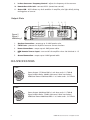
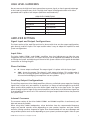
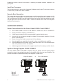
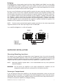
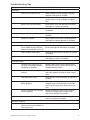
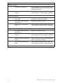
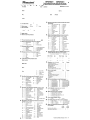
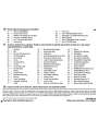
OWNER'S MANUAL
Am p l i f i er
MODEL
CO500.1
CO800.1
TABLE OF CONTENTS
English . . . . . . . . . . . . . . . . . . . . . . . . . . . . . . . . . . . . . . . . . . . . . . . . . . . . . . . . . . . . . . . . . . . . 1
Français . . . . . . . . . . . . . . . . . . . . . . . . . . . . . . . . . . . . . . . . . . . . . . . . . . . . . . . . . . . . . . . . . . 15
Español. . . . . . . . . . . . . . . . . . . . . . . . . . . . . . . . . . . . . . . . . . . . . . . . . . . . . . . . . . . . . . . . . . . 25
Deutsche . . . . . . . . . . . . . . . . . . . . . . . . . . . . . . . . . . . . . . . . . . . . . . . . . . . . . . . . . . . . . . . . . 35
Italiano. . . . . . . . . . . . . . . . . . . . . . . . . . . . . . . . . . . . . . . . . . . . . . . . . . . . . . . . . . . . . . . . . . . 45
Português . . . . . . . . . . . . . . . . . . . . . . . . . . . . . . . . . . . . . . . . . . . . . . . . . . . . . . . . . . . . . . . . 55
Introduction. . . . . . . . . . . . . . . . . . . . . . . . . . . . . . . . . . . . . . . . . . . . . . . . . . . . . . . . . . . . . . . . 2
What’s in the Box . . . . . . . . . . . . . . . . . . . . . . . . . . . . . . . . . . . . . . . . . . . . . . . . . . . . . . . . . . . 2
Practice Safe Sound™ . . . . . . . . . . . . . . . . . . . . . . . . . . . . . . . . . . . . . . . . . . . . . . . . . . . . . . . . 2
Tools of the Trade . . . . . . . . . . . . . . . . . . . . . . . . . . . . . . . . . . . . . . . . . . . . . . . . . . . . . . . . . . . 2
End Panel Layouts . . . . . . . . . . . . . . . . . . . . . . . . . . . . . . . . . . . . . . . . . . . . . . . . . . . . . . . . . . . 3
CEA Specifications. . . . . . . . . . . . . . . . . . . . . . . . . . . . . . . . . . . . . . . . . . . . . . . . . . . . . . . . . . . 4
Amplifier Settings . . . . . . . . . . . . . . . . . . . . . . . . . . . . . . . . . . . . . . . . . . . . . . . . . . . . . . . . . . . 5
Signal Input and Output Configurations . . . . . . . . . . . . . . . . . . . . . . . . . . . . . . . . . . . . 5
Input Gain . . . . . . . . . . . . . . . . . . . . . . . . . . . . . . . . . . . . . . . . . . . . . . . . . . . . . . . . . . . . . 5
Phase Switches . . . . . . . . . . . . . . . . . . . . . . . . . . . . . . . . . . . . . . . . . . . . . . . . . . . . . . . . . 5
Auxiliary Output Configurations . . . . . . . . . . . . . . . . . . . . . . . . . . . . . . . . . . . . . . . . . . . 5
Internal Crossover Configurations . . . . . . . . . . . . . . . . . . . . . . . . . . . . . . . . . . . . . . . . . . 5
Low-Pass Crossover . . . . . . . . . . . . . . . . . . . . . . . . . . . . . . . . . . . . . . . . . . . . . . . . . . . . . . 5
Remote Gain Operation . . . . . . . . . . . . . . . . . . . . . . . . . . . . . . . . . . . . . . . . . . . . . . . . . . 5
Amplifier Wiring . . . . . . . . . . . . . . . . . . . . . . . . . . . . . . . . . . . . . . . . . . . . . . . . . . . . . . . . . . . . 6
Power Connections for the Orion Cobalt CO500.1 and CO800.1 . . . . . . . . . . . . . . . . . 6
Speaker Connections . . . . . . . . . . . . . . . . . . . . . . . . . . . . . . . . . . . . . . . . . . . . . . . . . . . . 6
Bridging . . . . . . . . . . . . . . . . . . . . . . . . . . . . . . . . . . . . . . . . . . . . . . . . . . . . . . . . . . . . . . . 6
Amplifier Installation . . . . . . . . . . . . . . . . . . . . . . . . . . . . . . . . . . . . . . . . . . . . . . . . . . . . . . . . 7
Choosing Mounting Locations . . . . . . . . . . . . . . . . . . . . . . . . . . . . . . . . . . . . . . . . . . . . . 7
Passenger Compartment . . . . . . . . . . . . . . . . . . . . . . . . . . . . . . . . . . . . . . . . . . . . . . . . . 7
Trunk Compartment . . . . . . . . . . . . . . . . . . . . . . . . . . . . . . . . . . . . . . . . . . . . . . . . . . . . . 8
General Precautions and Installation Tips. . . . . . . . . . . . . . . . . . . . . . . . . . . . . . . . . . . . 8
Step By Step Installation. . . . . . . . . . . . . . . . . . . . . . . . . . . . . . . . . . . . . . . . . . . . . . . . . . 8
Set Up and Troubleshooting . . . . . . . . . . . . . . . . . . . . . . . . . . . . . . . . . . . . . . . . . . . . . . . . . . 9
Testing the System . . . . . . . . . . . . . . . . . . . . . . . . . . . . . . . . . . . . . . . . . . . . . . . . . . . . . . 9
Adjusting the Sound of the System. . . . . . . . . . . . . . . . . . . . . . . . . . . . . . . . . . . . . . . . . 9
Troubleshooting Tips . . . . . . . . . . . . . . . . . . . . . . . . . . . . . . . . . . . . . . . . . . . . . . . . . . . 11
Specifications. . . . . . . . . . . . . . . . . . . . . . . . . . . . . . . . . . . . . . . . . . . . . . . . . . . . . . . . . . . . . . 13
Warranty . . . . . . . . . . . . . . . . . . . . . . . . . . . . . . . . . . . . . . . . . . . . . . . . . . Back cover
© 2007 directed electronics—all rights reserved
1
INTRODUCTION
Thank you for your purchase of a Orion Cobalt power amplifier. Each Orion Cobalt amplifier is
designed to be the leader in its class offering the most power, advanced features, and extreme
ease of use. In high-end sound systems or high SPL systems, Orion Cobalt amplifiers will give you
years of trouble-free performance.
L
CO500.1 - 250 Watt - single-channel Class A/B amplifier with built-in fully variable
low-pass crossover. Equipped with remote gain, the CO500.1 is capable of one-channel
operation with a maximum power of 500 W into 2 ohm.
L
CO800.1 - 400 Watt - single-channel Class A/B amplifier with built-in fully variable
low-pass crossover. Equipped with optional remote gain, the CO800.1 is capable of
one-channel operation with a maximum power of 800 Watts into 2 ohm.
The installation of all Orion Cobalt components will determine the overall performance result.
Improper installation will not only limit the performance of your Orion Cobalt system but also
potentially compromise the reliability of this amplifier. To ensure proper sonic results and component reliability, please refer to your authorized dealer for installation assistance or advice. If
you decide to perform the installation yourself, be sure to read the entire manual before beginning the installation.
WHAT’S IN THE BOX
L
(1) Amplifier
L
(2) Spare fuse(s)
L
(4) #8 self-tapping black Phillips head pan head screws
L
(1) Amplifier installation and operation manual
L
(1) RGC-2 Remote bass control
PRACTICE SAFE SOUND™
Continuous exposure to sound pressure levels over 100dB may cause permanent hearing loss.
High power automotive sound systems can generate sound pressure levels in excess of 130dB.
When playing your system at high levels, please use hearing protection and avoid long term
exposure.
Model:
__________________________________________________
Serial Number:
__________________________________________________
Date of Purchase: __________________________________________________
2
© 2007 directed electronics—all rights reserved
TOOLS OF THE TRADE
Listed next are the majority of the tools required to perform an installation. Having the proper
tools will make the installation that much easier. Some of these tools are necessities; some will
just make the job easier.
L
Allen Wrenches (2mm, 3mm & 4mm)
L
DMM or VOM
L
Electric drill with assorted drill bits
L
Grommets
L
Heat shrink tubing
L
Marking pen
L
Phillips and flat blade screw drivers
L
Nylon tie straps
L
Pliers (standard and needle nose)
L
Wire crimper
L
RTA (real time analyzer)
L
Wire cutters
L
Soldering iron and solder
L
Wire strippers
L
Utility knife
L
Wire brush or sandpaper for chassis grounding
L
Reference CD with 1 kHz Sine Wave at 0dB level (all bits high)
END PANEL LAYOUTS
Input Plate
1
2
3
4
5 6
7 8
9
10
11
Figure 1
Figura 1
Abbildung 1
1.
Power LED - When lit indicates that the amplifier is on.
2.
High Level Input - Connect speaker output from factory radio to amplifier, will auto
sense signal from radio and turn amplifier on when needed, turn off after 1 minute
without signal.
3.
RCA Outputs - provides a full range signal for easy connection to additional amplifiers.
4.
RCA Inputs - Accepts RCA input from a source unit, preamplifier, or equalizer.
5.
Gain Control - Continuously adjusts from 150mV to 8V input to obtain full power
output.
6.
Phase Control Switch - Allows for adjustment of phase and makes bridging amplifiers possible.
7.
LPF, FULL, Switch - Selects either Lo-pass crossover or full range crossover.
8.
Bass Boost Switch - Adjusts bass gain in three steps (0dB, 6dB, & 12dB).
© 2007 directed electronics—all rights reserved
3
9.
Lo-Pass Crossover Frequency Control - adjusts the frequency of the crossover.
10. Remote Bass Gain Jack - connects RGC-2 (remote bass control).
11. Status LED - Will indicate any fault condition in amplifier, also lights briefly during
muting phase of turn-on.
Output Plate
1
2
2
3
4
5
Figure 2
Figura 2
Abbildung 2
1.
Speaker Connections - accepts up to 12 AWG speaker wire.
2.
2 ATC Fuses - protects the amplifier from over current situations.
3.
Power Connections - accepts up to 4 AWG power cables.
4.
REM Remote Turn-on Input - turns on/off the amplifier when fed Switched 9 - 15
V+.
5.
Ground Connection - accepts up to 4 AWG ground cable.
CEA SPECIFICATIONS
CO500.1
Power Output: 175 Watts RMS x 1 at 4 ohms and < 1% THD+N
Signal to Noise Ratio: -80 dBA (reference 1 Watt into 4 ohms)
Additional Power: 250 Watts RMS x 1 at 2 ohms and < 1% THD+N
CO800.1
Power Output: 300 Watts RMS x 1 at 4 ohms and < 1% THD+N
Signal to Noise Ratio: -75 dBA (reference 1 Watt into 4 ohms)
Additional Power: 400 Watts RMS x 1 at 2 ohms and < 1% THD+N
4
© 2007 directed electronics—all rights reserved
HIGH LEVEL HARNESSES
Do not connect the high level input connections to power, signal, or chassis ground as damage
to the head-unit outputs may result. The high-level inputs are designed to work with either
grounded or BTL speaker level outputs (found on most head units).
HIGH LEVEL CONNECTIONS
WIRE COLOR
Black
INPUT CONNECTION
Ground
White/Black
- Left channel
White
+ Left channel
Gray/Black
- Right channel
Gray
+ Right channel
AMPLIFIER SETTINGS
Signal Input and Output Configurations
The input section of the amplifier consists of a phase switch that sets the output configuration,
gain controls, and RCA inputs. The input section makes it easy to adapt this amplifier to most
system configurations.
Input Gain
The Orion Cobalt CO500.1 and CO800.1 amplifiers have level adjustments to allow for easy
integration with any source unit. The input sensitivity can be adjusted from 200mV to 5V. Refer
to Testing the System and Adjusting the Sound of the System sections of this guide for detailed
instructions on setting the gain.
Phase Switches
L
0° - leaves output unaffected. The output signal is in phase with the input signal.
L
180° - inverts the output. The channel is 180° output of phase. This configuration is
useful for inverting the phase of subwoofers to improve staging in a vehicle. This is
also used when bridging two amplifiers into one speaker.
Auxiliary Output Configurations
The auxiliary outputs on Orion Cobalt amplifiers offer easy, unlimited system expansion. Routing
signal from a source unit, pre-amplifier, or equalizer is a matter of connecting RCAs to the RCA
Inputs and the RCA outputs to your next Orion Cobalt amplifier in the signal chain. The signal
passes through a buffer stage so that several amplifiers can be daisy chained without signal loss
or overloading of the source unit. This maximizes the signal output and minimizes the potential
for system noise.
Internal Crossover
The crossover section of the Orion Cobalt CO500.1 and CO800.1 amplifiers is continuously variable and extremely flexible.
When using Orion Cobalt loudspeakers, minor deviations from the recommended frequency
ranges can provide superior results depending on your speaker locations and your vehicle
acoustics. Setting crossover frequencies higher than recommended will not cause damage and
may provide superior sonic results depending on your system's performance goals. Refer to your
© 2007 directed electronics—all rights reserved
5
loudspeaker owner's manual for assistance in choosing the proper crossover frequencies for
your system.
Low-Pass Crossover
The low-pass crossover is active with a 2nd order (12dB per octave) slope. The low-pass crossover
is continuously variable from 50Hz to 500Hz.
Remote Bass Operation
The remote bass port provides easy remote access to the internal bass gain structure of the
power amplifier. The bass gain is centered at 44Hz. The RGC-2 plugs into the amplifier via the
1/8" mini jack plug. The RGC-2 can be installed in the front of the vehicle to control the amplifier bass gain level. The RGC-2 can be used as a bass level control when used on an amplifier
dedicated to subwoofers.
AMPLIFIER WIRING
Power Connections for the Orion Cobalt CO500.1 and CO800.1
L
Orion Cobalt CO500.1 Fuse Size: 2 x 20 AMP ATC / CO800.1 Fuse Size: 2 x 30 AMP ATC
L
Power connections accept up to 4 AWG wire.
L
4 AWG power and ground wire recommended for optimal performance.
L
Connect 12V+ to the battery through fuse holder. This connection provides +12V main
power to the amplifier.
L
Power wire must be fused no more than 18" from battery.
L
Ground amplifier to a good chassis ground as close as possible to the amplifier.
L
Connect REM terminal to remote turn-on lead from source unit. This connection provides +12V power to turn-on the amplifier.
L
Add extra ground wire between the negative terminal of the battery and the chassis.
Speaker Wiring Diagram CO500.1/CO800.1
The Orion Cobalt CO500.1 and CO800.1 amplifiers offer two positive and two negative output
terminals for ease of connecting the speakers to the amplifier. Since these are mono amplifiers, the
speaker connectors are paralleled internally. Each amplifier is stable to 2.
Single 2 speaker
-
Figure 3
Figura 3
Abbildung 3
6
-
24
+
+
or
2 ea. of 4 speakers
-
-
+
+
4
4
© 2007 directed electronics—all rights reserved
Bridging
For bridging into a single speaker load, the Orion Cobalt CO500.1 and CO800.1 have the ability
to be bridged with another amplifier of the same model. To do this you must set the PHASE
switch on the (slave) amp, move the phase switch from 0 to 180, exactly opposite of the master
amp. Refer to the Phase Switch section of this guide.
Be sure to set all adjustment on both amplifiers exactly the same except for the phase switch.
The phase switch on the master amplifier should be 0 and the slave amplifier should be 180.
For the speaker connections, connect the positive (+) speaker lead from the speaker to the positive (+) speaker terminal of the master amplifier. On the negative (-) speaker connection, take
the negative (-) speaker terminal of the master amplifier and connect it directly to the negative (-) speaker terminal of the (slave) amplifier. The remaining positive (+) speaker terminal of
the (slave) amplifier must be connected to the negative (-) speaker lead from the speaker. The
impedance of the speaker must not be less than 4 ohms
NOTE:
For best results, connect both negative speaker terminals on the master amp to both
negative terminals on the slave amp using at least 12 AWG cable.
2 ea. amplifiers bridged to 1 ea. 4 or 8 speaker
MASTER
SLAVE
PHASE 0º
PHASE 180º
-
Figure 4
Figura 4
Abbildung 4
-
+
+
-
-
+
+
4
AMPLIFIER INSTALLATION
Choosing Mounting Locations
The location of your amplifier will depend on several important issues. Due to the low profile
size of the Orion Cobalt amplifiers, there are many possible installation locations that will yield
satisfactory amplifier performance. Always mount the amplifier in a place that protects the
amplifier from the elements. In addition, mount the amplifier on a stable, flat surface.
NOTE:
Mounting amplifiers upside down is not recommended and may cause premature
thermal shutdown.
WARNING!
Do not mount any amplifier in the engine compartment. Amplifiers are not
designed to endure the harsh environment of the exterior elements.
Passenger Compartment
If you are going to mount the amplifier in the passenger compartment, make sure you have
adequate room for ventilation. The amplifiers have been designed to make under-seat mounting possible. When mounting your amplifier under a seat or similar area, keep a minimum of 1"
of clearance around the amplifier for adequate cooling.
© 2007 directed electronics—all rights reserved
7
Trunk Compartment
Mounting your amplifier in the trunk provides excellent performance as long as you do not
restrict the airflow around the heatsink of the amplifier. For optimal results, mount the amplifier
with as much clearance as possible. This type of mounting will yield the best cooling due to the
convection effect of the amplifier chassis.
General Precautions and Installation Tips
WARNING!
Be careful not to cut or drill into gas tanks, fuel lines, brake lines, hydraulic lines,
vacuum lines, or electrical wiring when working on your vehicle.
Disconnect the vehicle's ground wire at the battery before making or breaking connections to
the audio system's power supply terminals.
Do not use this amplifier unmounted. Failing to securely mount the amplifier can result in
damage or injury, particularly in the event of an accident. An unmounted amplifier becomes a
dangerous projectile in the event of a crash. Never mount the amplifier where it might get wet.
Mount the amplifier so the wire connections will not be pulled. Route the wires where they will
not be scraped, pinched or damaged in any fashion.
The +12V power supply wire must be fused as close as possible to the battery terminal, ideally
within 18". Use the recommended fuse size or circuit breaker listed in the Power Connections
section of this manual.
If you need to replace the fuse plugged into the side of the amplifier, replace the fuse with the
same size ATC / MAXI type fuse that came with the amplifier. If you are not sure as to the correct
value, refer to the Power Connections section of this manual for details. Using a higher current
fuse may result in damage to the amplifier that is not covered under warranty.
NOTE:
Make sure all the equipment in the system is turned off when making or breaking connections to the input RCAs or speaker terminals. Turn on the system and slowly turn up
the volume control only after double checking all wire connections.
Power for systems with a single amplifier can be supplied by most automotive electrical systems.
Systems with multiple amplifiers may require a higher capacity battery, alternator or the use of a
storage capacitor. We strongly recommend the use of a Directed Audio Essentials power capacitor with an extra battery in larger stereo systems.
Orion Cobalt amplifiers generate a certain amount of heat as part of normal operation. Be sure
the area around the amplifier is unobstructed to allow adequate air circulation. Remember,
beach blankets, last week's laundry, school books and homework papers located on top of the
amplifier do not improve air flow and may become damaged.
Step By Step Installation
8
Step 1
Determine the location for the amplifier. Refer to the Choosing Mounting
Locations section of this guide for detailed information.
Step 2
Decide on the system configuration for your amplifier. For system suggestions,
refer to the Speaker Connections section of this guide.
Step 3
Run all the wires from the amplifier location to the speakers, source unit, and battery. Do not connect the battery at this time. Be sure to run RCAs and power and
speaker wires away from factory electrical wires and system as they pose a great
potential for induced system noise.
Step 4
Pre-drill amplifier mounting holes. Be sure to "think before you drill". Gas tanks,
fuel lines, and other obstructions have a nasty way of hiding themselves. For best
© 2007 directed electronics—all rights reserved
results use a marking pen to mark the mounting holes and pre-drill these holes
with a standard 1/8" drill bit.
Step 5
Mount the amplifier. Make sure the amplifier is mounted on a flat surface. If this
is not possible, do not over tighten the screws so that the chassis of the amplifier
is twisted or bent.
Step 6
Turn the vehicle's key switch to the off position.
Step 7
Disconnect the vehicle's battery ground terminal.
Step 8
Connect power wires to the amplifier (ground first, then 12 V(+) and REM).
Step 9
Connect the RCA and speaker wires to the amplifier. Check the quality of your
speakers and signal connections. This will determine the ultimate performance of
your Orion Cobalt amplifier. Refer to the Signal Input and Output Level Controls
and Speaker Connections sections of this guide for correct wiring instructions.
Step 10
Reconnect the ground terminal to the battery after power, speaker, and RCA connections are completed.
Step 11
Set crossovers. Refer to the Internal Crossover Configuration section of this manual
for detailed instructions.
Step 12
Once satisfied that all connections and settings are correct, install the fuse located
near the vehicle's battery and proceed to the Testing the System section of this
manual.
WARNING!
Never exceed the recommended fuse size of this amplifier. Failure to do so will
result in the voiding of your warranty and possible damage to the amplifier.
SET UP AND TROUBLESHOOTING
Testing the System
After you have completed the installation, you need to test the system. This will help ensure years
of trouble-free operation. Please refer to the listed steps below when testing the sound of your
Orion Cobalt system.
Step 1
Check all the wiring connections to be sure they are correct and secure.
Step 2
Turn the signal source volume control all the way down. Set any tone controls to
their flat or defeated positions. This includes the loudness control.
Step 3
Turn the level controls of the amplifier to their minimum positions.
Step 4
Turn the source unit on. Check to see if the power LED located on the connection
side of the amplifier is on. If not, please refer to the Power Connections and the
Troubleshooting Tips sections of this manual for instructions.
Step 5
If using an aftermarket source unit, turn the level controls of the amplifier about
one quarter of a turn. Slowly increase the volume level of the source unit to so that
you can hear the output of the system. If no sound is heard or if the output is distorted, turn the system off immediately. Refer to the Power Connections and the
Troubleshooting Tips sections of this manual to solve your installation problems.
Step 6
Check to make sure the output for each channel is correct. If the active crossovers
are used, check to make sure that each output is correct from the amplifier. When
using active crossovers on midrange and tweeters, do not use crossover frequencies lower than recommended. If the system is not configured properly, refer to
the Internal Crossover Configuration section of this manual and take corrective
action.
Step 7
If the output is clear and undistorted, continue to the Adjusting the Sound of the
© 2007 directed electronics—all rights reserved
9
System section of this manual.
Adjusting the Sound of the System
Once you have checked the system's operation, adjust the sound of the system. Adjusting the
sound of the system is accomplished by setting the level controls and adjusting the internal
crossovers.
10
Step 1
Turn the signal source volume control all the way down. Set any tone controls to
their flat or defeated positions. This includes the loudness control.
Step 2
Turn the level controls of the amplifier to their minimum positions.
Step 3
Choose music with high dynamic content that you like, with which you are familiar, and will be used most often in the system.
Step 4
Turn the source unit's volume control up to its highest undistorted output level. If
you lack test equipment, this point occurs between 3/4 to full volume depending
on the quality of your source unit. Listen for any audible distortion. If any distortion is audible, reduce the volume of the source unit until you have an undistorted
output. Leave the volume control at this position during your system tuning.
Step 5
While listening to your chosen dynamic music, turn up the level control corresponding to the midrange output until you hear slight distortion and turn the
level control back slightly for an undistorted output. Depending on your system,
the midrange and tweeter output may be on the same output channels.
Step 6
Turn up the level control corresponding to the tweeter output until you hear
slight distortion and turn back the level control slightly for an undistorted output.
Depending on your system the midrange and tweeter output may be on the same
output channels.
Step 7
Fine-tune the output level between midrange and tweeters. Refer to the Internal
Crossover Configuration section of this manual for detailed instructions.
Step 8
Repeat Steps 5-7 for the rear speakers. If you do not have rear speakers continue
to Step 10.
Step 9
Set levels between the front and rear midrange and tweeters for optimum front/
rear balance.
Step 10
Turn up the level control corresponding to the woofer output until you hear slight
distortion and turn back the level control slightly for an undistorted output.
Step 11
Fine-tune the output level between satellite speakers and the woofers. Refer to
the Internal Crossover Configuration section of this manual for detailed instructions. If using an RGC-2, adjust the level to the bass output of the woofer to match
the sonic requirements of the system.
Step 12
Enjoy your awesome Orion Cobalt sound system.
© 2007 directed electronics—all rights reserved
Troubleshooting Tips
Symptom
Probable Cause
Action To Take
Low or no remote turn-on
Check remote turn-on voltage at voltage
amplifier and repair as needed.
Fuse blown
Check power wire's integrity and check for
speaker shorts. Fix as needed and replace
fuse.
Power wires not connected
Check power wire and ground connections
and repair or replace as needed.
Audio input not connected.
Check RCA connections and repair or replace
as needed.
Speaker wires not connected
Check speaker wires and repair or replace as
needed.
Speaker are blown
Check system with known working speaker
and repair or replace speakers as needed.
No output
Audio cycles on and off
Thermal protection engages
when amplifier heat sink temperature exceeds 50º C (122º F)
Make sure there is proper ventilation for amplifier and improve ventilation as needed.
Loose or poor audio input
Check RCA connections and repair or replace
as needed.
Loose power connections
Check power wires and ground connections
and repair or replace as needed.
Distorted output
Amplifier level sensitivity set
too high exceeding maximum
capability of amplifier
Readjust gain. Refer to the Adjusting the
Sound of the System section of this manual
for detailed instructions.
Impedance load to amplifier
too low
Check speaker impedance load, if below 2,
rewire the speakers to achieve higher impedance.
Shorted speaker wires
Check speaker wires and repair or replace as
needed.
Speaker not connected to amplifier properly.
Check speaker wires and repair or replace as
needed. Refer to the Speaker Connections
section of this manual for detailed instructions
Internal crossover not set properly for speakers
Readjust crossovers. Refer to the Internal
Crossover Configuration section of this
manual for detailed instructions.
Speakers are blown
Check system with known working speakers
and fix or replace as needed.
Poor bass response
Speakers wired with wrong
polarity causing cancellation at
low frequencies.
© 2007 directed electronics—all rights reserved
Check speaker polarity and fix as needed.
11
Symptom
Probable Cause
Action To Take
Poor bass response
Crossover set incorrectly
Reset crossovers. Refer to the Internal Crossover Configuration section of this manual for
detailed instructions.
Impedance load at amplifier is
too low.
Check speaker impedance load if below 2,
rewire speakers to achieve higher impedance
.
Battery fuse blowing
Short in power wire or incorrect wiring.
Check power wires and ground connections
and repair or replace as needed.
Fuse used is smaller than recommended.
Replace with proper fuse size.
Actual current exceeds fuse
rating.
Check speaker impedance load if below 2,
rewire speakers to achieve higher impedance
.
Amplifier fuse blowing
12
Fuse used is smaller than recommended.
Replace with proper fuse size.
Impedance load at amplifier is
too low.
Check speaker impedance load if below 2,
rewire speakers to achieve higher impedance
.
Speaker is blown with shorted
outputs
Check system with known working speakers
and fix or replace as needed.
Actual current exceeds fuse
rating
Check speaker impedance load if below 2,
rewire speakers to achieve higher impedance
.
© 2007 directed electronics—all rights reserved
SPECIFICATIONS
Amplifier Section
CO500.1
CO800.1
Power Output in Watts RMS, 4 Ohms
175 x 1
300 x 1
Power Output in Watts RMS, 2 Ohms
250 x 1
400 x1
Externally Bridgeable
yes
yes
Remote Gain Function
yes
yes
Distortion at Rated Power
< 0.9% THD+N
< 0.9% THD+N
Frequency Response
20Hz to 30kHz
+0, -1dB
20Hz to 30kHz
+0, -1dB
Linear Bandwidth
20Hz to 20kHz
±3dB
20Hz to 20kHz
±3dB
Damping Factor
> 150
> 150
Input Sensitivity
rms
rms
Input Impedance
80k
80k
Fuse Type
(2) 20 Amp ATC
(2) 30 Amp ATC
Dimensions
11.4" x 8.1" x 2.1"
13.4" x 8.1" x 2.1"
Weight
6.3 lbs.
7.3 lbs.
Low Pass Crossover
Continuously variable/
2nd Order
Continuously variable/
2nd Order
Low Pass Frequency Range
50Hz to 500Hz
50Hz to 500Hz
Crossover Section
Continuous 2 load 20Hz to 200Hz, < 0.1% THD, with input voltage at 13.8VDC.
© 2007 directed electronics—all rights reserved
13
NOTES
_______________________________________________________
_______________________________________________________
_______________________________________________________
_______________________________________________________
_______________________________________________________
_______________________________________________________
_______________________________________________________
_______________________________________________________
_______________________________________________________
_______________________________________________________
_______________________________________________________
_______________________________________________________
_______________________________________________________
_______________________________________________________
_______________________________________________________
_______________________________________________________
_______________________________________________________
_______________________________________________________
_______________________________________________________
_______________________________________________________
_______________________________________________________
_______________________________________________________
_______________________________________________________
_______________________________________________________
_______________________________________________________
_______________________________________________________
_______________________________________________________
_______________________________________________________
_______________________________________________________
_______________________________________________________
_______________________________________________________
14
© 2007 directed electronics—all rights reserved
™
WARRANTY
LIMITED ONE-YEAR CONSUMER WARRANTY/*LIMITED TWO-YEAR CONSUMER WARRANTY FOR AUTHORIZED
DIRECTED DEALER PURCHASE & INSTALLATION
Directed Electronics (herein “Directed”) promises to the original purchaser of the subwoofer or amplifier, as
applicable (herein “Unit” or “Product”), to repair or replace with a new or refurbished Unit (at Directed’s
sole and absolute discretion) should the Unit prove to be defective in workmanship or material under normal
use, for a period of *two-years from the date of purchase from the authorized Directed dealer PROVIDED
the Unit was purchased and installed by an authorized Directed dealer. During this *two-year period, there
will be no charge for the repair or replacement PROVIDED the Unit is returned to Directed (DO NOT RETURN
THE ENTIRE ENCLOSURE. PLEASE RETURN THE WARRANTIED UNIT ONLY.), shipping prepaid, along with the
required proof of installation, the bill of sale or other dated proof of purchase, and the consumer’s contact
information. If the Unit is installed by anyone other than an authorized Directed dealer, the warranty period
will be one-year from the date of purchase. This warranty is non-transferable and does not apply to any Unit
that has been modified or used in a manner contrary to its intended purpose, and does not cover damage to
the Unit caused by installation or removal of the Unit. During this one-year period, there will be no charge
for the repair or replacement PROVIDED the Unit is returned to Directed, shipping pre-paid, along with
the bill of sale or other dated proof of purchase and the consumer’s contact information. This warranty is
void if the product has been damaged by accident or unreasonable use, neglect, improper service or other
causes not arising out of defects in materials or construction. This warranty does not cover the elimination
of externally generated static or noise, or the correction of antenna problems or weak reception, damage to
speakers, accessories, electrical systems, cosmetic damage or damage due to negligence, misuse, failure to
follow operating instructions, accidental spills or customer applied cleaners, damage due to environmental
causes such as floods, airborne fallout, chemicals, salt, hail, lightning or extreme temperatures, damage due
to accidents, road hazards, fire, theft, loss or vandalism, damage due to improper connection to equipment
of another manufacturer, modification of existing equipment, or Product which has been opened or tampered for any reason. Units which are found to be damaged by abuse resulting in thermally damaged voice
coils are not covered by this warranty but may be replaced at the absolute and sole discretion of Directed.
Unit must be returned to Directed (DO NOT RETURN THE ENTIRE ENCLOSURE. THE UNIT ENCLOSURE IS COVERED BY A SEPARATE 90-DAY LIMITED CONSUMER WARRANTY. PLEASE ONLY RETURN THE WARRANTIED
UNIT UNLESS A WARRANTY CLAIM IS BEING MADE FOR THE ENCLOSURE.), postage pre-paid, with bill of sale
or other dated proof of purchase bearing the following information: consumer’s name, telephone number,
and address, authorized dealer’s name and address, and product description. Unit must be returned to the
following address: ATTN: WARRANTY DEPARTMENT, Directed Electronics , 1 Viper Way, Vista, CA 92081. Note:
This warranty does not cover labor costs for the removal and/or reinstallation of the Unit. IN ORDER FOR
THE TWO-YEAR WARRANTY TO BE VALID, YOUR UNIT MUST BE SHIPPED WITH PROOF OF INSTALLATION BY
AN AUTHORIZED DIRECTED DEALER. ALL UNITS RECEIVED BY DIRECTED FOR WARRANTY REPAIR WITHOUT
PROOF OF DIRECTED DEALER INSTALLATION AND PURCHASE WILL BE COVERED BY THE LIMITED 1 YEAR
WARRANTY.
BY PURCHASING THIS PRODUCT, ALL WARRANTIES INCLUDING BUT NOT LIMITED TO EXPRESS WARRANTY,
IMPLIED WARRANTY, WARRANTY OF MERCHANTABILITY, FITNESS FOR PARTICULAR PURPOSE, AND WARRANTY OF NON-INFRINGEMENT OF INTELLECTUAL PROPERTY ARE EXPRESSLY EXCLUDED TO THE MAXIMUM
EXTENT ALLOWED BY LAW, AND DIRECTED NEITHER ASSUMES NOR AUTHORIZES ANY PERSON TO ASSUME
FOR IT ANY LIABILITY IN CONNECTION WITH THE SALE OF THE PRODUCT. DIRECTED HAS ABSOLUTELY NO
LIABILITY FOR ANY AND ALL ACTS OF THIRD PARTIES INCLUDING ITS AUTHORIZED DEALERS OR INSTALLERS. IN NO EVENT WILL DIRECTED BE LIABLE FOR ANY INCIDENTAL, SPECIAL OR CONSEQUENTIAL DAMAGES
(INCLUDING LOSS OF PROFITS). BY PURCHASING THIS PRODUCT, THE CONSUMER AGREES AND CONSENTS
THAT ALL DISPUTES BETWEEN THE CONSUMER AND DIRECTED SHALL BE RESOLVED IN ACCORDANCE WITH
CALIFORNIA LAWS IN SAN DIEGO COUNTY, CALIFORNIA. This warranty is only valid for sale of Product within
the United States of America. Product sold outside of the United States of America is sold “AS-IS,” and shall
have NO WARRANTY, express or implied. Some states do not allow limitation on how long an implied warranty lasts. In such states, the limitation or exclusions of this Limited Warranty may not apply. Some states do
not allow the exclusion or limitation of incidental or consequential damages. In such states, the exclusion or
limitation of this Limited Warrantymay not apply to you. This Limited Warranty gives you specific legal rights,
and you may have other rights which vary from state to state.
920-0033 04-07
For more information on Orion or WCC products please visit www.orioncaraudio.com
Directed Electronics is an
ISO 9001 registered company.
Directed Electronics is committed to delivering
world class quality products and services
that excite and delight our customers.
Vista, CA 92801
DIRECTED.COM
© 2007 Directed Electronics. All rights reserved
For more information on Orion products please visit www.orioncaraudio.com
G42115
2007-11