1
SEARS
OWNERS
MANUAL
MODEL NO.
919.154020
919.154120
919.154320
919.154420
CRAFTSMAN
PERMANENTLY LUBRICATED
AIR COMPRESSOR
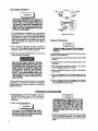
Record in the spaces provldc_L
(1) The model number whl<;h _un be
found on the laber on the ba¢_ of the
Shroud.
Listed
(2) The
code number which oan be
fourKJon the fob label on the baok of
the air tank.
Air
(3) The Manufacturers Number (ASME
compressor
B
i
IMPORTANT.,
Read the Safety Guidelines
and All lnstruott0ns
Carefully Before Operating
ASSEMBLY
OPERATION
MAINTENANCE
REPAIR PARTS
Code Compre880r_ Only) Is locatsd
on the motel data plate whl©h is
v_ded onto the I_ck _fde of the air
tzn_, (Thia ¢eta plzrbpi= painted the
iseme _elOr aS the tank.)
Pvatafnthese numbers for future
refePen_,
Model No.
Code No.
a_. No.
Sears, Roebuck and Co,, Chicago,
S)-30-_..4,.B
lotae
IL 60684
U,S,A,
TABLE OF CONTENTS
Page
WARRANTY .........................................................
3
SAFETY GUIDELINES ................................................
3
WARNING CHART .......................................................
3
SPECiRCATION
5
CHART ................................................
GLOSSARY ...................................................................
ACCESSORIES FOR USE W!TH SEARS AIR COMPRESSORS
5
,,
6
GENERAL INFORMATION .............................................
6
DESCRIPTION OF OPERATION ..................................
6
ASSEMBLY INSTRUCTIONS ............................................
ToolsN_¢C!edfor Ass_mbty..............................................
Installing Wheels, Handle, Rubber foot strip...............................
Installing Regulator ....................................................
INSTALLATION AND BREAK-IN PROCEDURES ..........................
location of Air Compressor.............................................
7
7
7
7
7
7
Lubric,_ttonand 0it .....................................................
7
_._t_'_fon Cord_ .......................................................
7
GroundingInst_'uctions
.................................................
8
greak-ln
Procedures
....................................................
8
OPERATING PROCEDURES
MAINTENANCE
........................................
8
.........................................................
g
Air _Iter ..............................................................
9
Check V_tve- Repl_ceme_ ...........................................
9
Safety _aJve - Inspection
8
...........................................
Motor...................................................................
9
STORAGE ..............................................................
lo
TROUBLESHOOTING
GUIDE ........................................
AIR COMPRESSOR DIAGRAM ......................................
Part,=,List ....................................................................
1o
t:2
13
COMPRESSOR PUMP DIAGRAM .......................................
14
ParlSList........................................................
15
HOW TO ORDER REPAIR PARTS ........................................
16
FULL ONE YEAR WARRANTY
AIR COMPRESSORS
If this air compressorfails due to a defect In material or workmanshipwithin one year from the
date of purchases.RETURN IT TO THE NEAREST SEARS SERVICE GENTERtOEPARTMET,_r
THROUGHOUT THE UNITED STATESAND SEARS WILL REPAIR IT,FREE OF CHARGE,
if this air compressorisused for commercial or rental purposes,the warrantywill apptyfor nlnety
days from the date of purchase.
Thiswarrantygives you specificlega{ rights and you may have other nghtswhich vary from state
tostate..
Sears, Roebuck and Co. Sears Tower, Dept. 6_1/731A, Chicago, 1L 60684
SAFETY GUIDELINES
Thts manual containsinformation that is importantfor you to knowand understand,This Informationrelates to protectingYOUR SAFETY and PREVENTING EQUIPMENT PROBLEMS To help
you recognize this information, we use the followingsymbols°Please read the manual and pay
attentionto these sectlort._.
URGENT
SAFETY
INFORMATION
,- A
HAZARD
THAT WILL CAUSE SERIOUS
INJURY OR LOS_; OF LIFE,
IMPORTANT SAFETY INFORMATION - A
HAZARD THAT MIGHT CAUSE SERIOUS
INJURY OR LOSS OF LIFE.
NOTE
information
equipment,
for preventing
damage to
informationthat you should pay special at_enlion to.
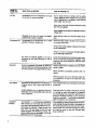
HAZARDS CAN OCCUR IF EQUIPMENT tS NOT USED PROPERLY,
PLEASE READ THE FOLLOWtNQ CHART,
WHAT TO
LOOK FOR
WHAT COULD HAPPEN
HOW TO PREVENT IT
Hot Parts
The compressor heed gets hot when the air
compressor Is running. If you touchit, you may
be seriously bumecL
Never touch the air compressorhead during or
immediatelyafter opert_tion_
Flammable
It is normal forthe motor and pressure switchto
spo.rt_ when operating, if the v_pors from
gasoline or other solvents come into ¢onte=¢t
w!ththesparks,they may ignite and c&usea fire
or explosion
Always operale the air compressor in wellventit=_d 8r€1_5:free ot ga3o_Jrt_
or artier_oJv_t
vapors, Do not operate the coml:_essornear the
spray area
,,H,,,I,,,
vapors
,,i,, i,
,,/
.....
:
W.ATT0
LOOK FOR
Nr Tank
WHAT COULD HAPPEN
HOW TO PREVENT IT
Modifications to the air compressorcan cause
the air tank to rupture or explode,
Do not adjust, remove or tamper with the safety
valve orpressureswitch. If safety valveor pressure
switch r_e=emen_ ;s necessary,a part with the
same rating must be used
Never use a mot0r withahlgher horsepower rating
than the one supplied.
Never replacetheair lan_ with a differentmo0el or
a large_tank,
Changingthe air tank will cause It to weaken.
The tank may rupture or exp!ode_
N_er ddlt{n_o,weld, or in any way modily the air
tank,
Compassed Air' Cornpr_'_ed sir can propeldust,dirt. or loose
partio[esit comes in contactwith,
N_werpolntany nozzfeor sprayertoward a person
or any part of the body,,
Always wearsafety gogglesOrglasseswhen using
the air compressor,
AF,,_ys turn the air compressoroff beforeattach-.
ing or removingaccessories,
Too much air pressure applied to air tools or
accessories cart cause damage or risk Of
bursting.
Eie ty
Che_k the m.anufactuter's m_(mum pressurerating for air tools 9.nd accessories.Rsguta_r outlet
pressure must never exceed the maximum _¢essure rating.
Your air compressorIs powered by electricity. Always unplug t!le air compressor prior1omalrtteLike any othereleGtdcaJlypDwereddevice, ifitis nonce ot repair,
not used properlyIt maycause electdeaJshock
Never use the air compressoroutdoors when it is
r_ning.
Always I_Ug the cord intoan ale€tricotcutter with
the specified voltage and adequate fuse
p_teetfon,
ToxicVapors
I!iS_rmal for€ompressedalr_contain
toxic
or Never dlrect|yInhale _hecompressedair produced
irritating vapors.8uoh vapor's are harmful if by this unit.
inhaled.
Certain materials you are spraying (like pairrl, Read and follow the safety Instructions provided
weed kiUe( sand or insecticide)may be harmful on the i_bel or safety data sheet for the matetla[
If you Inhale
them,
you arespraying.Use a respiratorma_k ilthere tsa
chance of tnh_tlng anything you are spraying,
Read =t instructions.., be ¢un_that the r_l_iral_r
mask is sultabte foryour application.
UnsuJtat_fe
Solvent=
4
The solvents!,t,1 - Trich!omethaneand M'elhylena Chloride Canchemlc_.tly react with aluminum u_edin paintspray g_Jr_,paintpumps,etc..,
and cause an explosion These solvents can
also react with galvani=od components and
cause corrosionand weakening of paris. This
does _lotaffect yourair compressor_but it may
affect the equipmentbeing u_d,
If
the material you intend 1ospraycontainsthe solventsltSled at l_ft [read the label or dale sheet},do
not u_ accessoriesthat contain aluminum or g_uvanlze_ part=. You musl eitherchang_ themateria_
you intend to spray, or use only stafnle=s _teel
spray equipment,
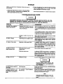
SPECIFICATION CHART
Mo_I No.
Horsepower
DisplacementCFM
Bore
Stroke
Voltage.SinglePhase
MinimumBranch CircuitRequirement
"'Fuse Type
Air Tank Capaclty
Approximate Cut-in Pressure
ApproximateCut-out Pressure
SCFM C_40 psig
SGFM ('.490 psfg
919.154020
2
I0,0
2%"
1,13'°
t?.0
"15amp_
"Fusetron"
•"TypeT
t2 g_L
80
100
70
5,6
919.1_20
2
100
_1/t"
1.13"
120
"15 arnps
"Fusetron"
"Type T
20 gel,
80
100
7O
5.8
919J54120
2
t0,0
_=_"
1,,13"
12.0
"15 amps
"Fusetron"
"Type T
12 gel ASME
80
_00
7,0
5.6
919.1_4420
2
10,0
_'_"
1.13'
t213
÷15amps
"Fusetmn•
**Type T
20 gal. ASME
80
I00
70
5.6
These compre_ors can be operated on a 15 amp Glrcutt if:
1. Voltage supply to clr=uit is normal.
2, Ciroutt Is not used to supply any otl_r electrical needs (lights, appliances, etc.)
3. Extension r._rds comply with specifications in owners manual.
4. Clrouit ts equipped with 15 amp otrcuit breaker or 15 amp Fuset_ronType "T" time delay tuse_
If any of the above conditlorm cannot be met, or if operation of the compressor repeatedly causes
Interruption of the power It may be necessary to operate it from a 20 amp €ircuit. It is not necessary to
changethe cord set.
"'A circuit breaker ie preferred. Use only a f,._seor circuitbreaker that is the same rating as the branch circuitthe air
compressorts operated on. II the air compressorIs conr_oled to a circuitprotected by fuses, use dueJelement time
delay fuses (Buss FuestronType "T" onty)
GLOSSARY
CFM: Cubic feet per minute.
SCFM: Standardcubicfeet per minute:a unitof measure of_Jrdelivery.
PSlG: Poundsper squareinch gauge;a unitof measure of pressure,
ASME: American Society of Mechanist Engineers;
made, tested, inspected and registered
tomeet the
stanches of the ASME,
U.L LISTED: S_mples ol compressor outfits, taken
from production,w_re submitted to U.L and found to
comply with their requirements for design and
performance.
ACCESSORIES
Cut-In Pressure: While the motor isoff, air tankpressure drops as you continue to use your ae,ces_ory.
When the_ankpressure drops toa certainlowlevellh_
motor wltl m-s_rt autorr=atioaJly.The low preesureet
which themotorautomatically re-startsis called'cuF]n
pre_ure".
Cut-Out Pressures: When you turnon yaur air corm
pressorand it begins torun, eir pressureIn theeir tank
begins to build, tt builds to a certain high pressure
before the motor automaticallyshuls off - protecting
your air tank from pressurehigher than its ¢_paclty.
The highpressureat whichthe motor shutsOffiScalled
"cut-out preesure'L
FOR USE WITH SEARS AIR COMPRESSORS
The followingaccessoriesare availablethroughtl_ecurrcnt general sales catalog or at full-line8cars stor_,
. SPRAY GUNS
• BLOW GUNS
• AIR CAULKING GUNS
• AIR POWERED WASHER GUNS
" SANDBLASTERS
• AIR BRUSHES
- AIR LINE FILTERS
, TiRE AIR CHUCKS
" PAINT TANK,._
, AIR TANKS
• INFLATER KIT_i
• QUICK CONNECTOR SETS
(various sizes)
• VISCOSIMETER
, AIR PRESSURE REQULATORS
• OIL FOG LUBRICATORS
. AIR TOOLS:
Sanders
Dfifis
tmpact wrenches
Hammers
• AIR HOSE;
W', %e"or% '_I.D.
in variOuSlengths
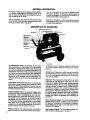
GENERAL INFORMATION
Youhave purchasedan aircompressorunitoonsisilngof
a 1 _'lir',der, sing_staga air compressorpump, an air
tank,air hose,wheels, handle, and associatedcontrols
Youwillalso lind an air chuck.
Your air compressorcan be used for operating paint
spray guns, air loois, caul_ng guns, grease guns, air
bruohes, sandbtaBtens,
or inflatingtires and plasticto_p_,
sprayingweed klllers, insecticides,etc.
T'-_sair compressor requires no oil, Now you can enjoy
all the benefffsof having an air compressorwltl_outever
havingto purchase,add or change oil
_p_ra_e air tran:dormerswhichcombine the functions
of air regulptionand/ofmoistureand dirtremovalshould
be usedwhere applicable.
DESCRIPTION OF OPERATION
D_JU_C_K
Air Compressor Pump: To compress air, the piston
moves up and downIn the cyllt_te_o
On the downstroke,
aimsdrawnin throughtheair intakevalves,The exhaust
valvererr_lnsctose_t.On the upstroke ofthepiston,a{ris
compressed. The intakevalves €_o=e_nd compressed
air is for_edout throughthe e_haus!valve, throughthe
outlet tube,lhmugh the checkvalve and into the air tank,
Working air is not _vallable untl_the compressorhas
raisedthe airtankp_essureabovethatrequired at the air
_utlet.
Check Valve;Wh_ file aircompressorIs operating, I._e
chock v_Jvo(s "open",allowing compressed air to enter
the aft tank. Whenthe air compressorreaches "cut-,out"
pre_eure,the checkvalve "=loses", allowing airpressure
tOn_m=tnInside the air tank,
Preaaure Releue Valve; The pressure release valve
located on theside ofthepressureswitch, is designedto
automatically release compr_8Od air from the com_essor ha_d and the outlet;tube whenthe _ir compressot reaches "cut-out" pm_;_ or is _hut off, If the air Is
notreleased, the motor willtry to=t¢,rt,but wigbe unable
t_. The pressurerel_=sevalveallows the motortor_._r t
freely.When the m_tor stops running,air will be heard
escapingfrom thevalvefor a few seconds. Noair should
be heardleaking when the motor is running,
Pressure Switch: The presSure swirchautomatically
start_themotorwhen the sir tl_,rtk
pressuredropsbeiOW
5
the f_otoryeel "¢ut,-in"pressure,tt _ops the motor when
the air tank pressure reaches the factory set =cut-out"
pmssL_e.
Safety Valve: If thepressure=witch does notshutoffthe
air compressor at itscut-outpressuresel_[ng,the safety
valvewillprotectagainsthigh pressureby'"poppingout_'
at iLspre-set p_ss_re.
Regulator: The air pressure coming fromthe air tan_ is
controlled by the regulator knob, Turn the knob
clcckwlse to incn_e pressureand counter.clockwise
to decrease pressure.To _rvoldminorre_djuslmentafter
ma_ng a change in pressures_tttng, alwaysapproach
the desired pressure from a i_wer pressure. When
reducing1tOma h_gherto a lowersetting,flintred_ce lo
some pressuretess th_n that desired, then bringup to
the desired pressure,.De pendingon the air requirements
of e_,ch particular accessory, the out(at regulated air
pressUr_ may h_v_ to be adjusted willie oper_ting
_ccessory,
Outlet Prauurl Gauge: The outlet pressuregauge
indicates the air pressure a'_aJlab_e
_t the ou_letside of
the taguiatOr,ThL_pressureis controlledby the regulator
and is atways less or eq_Jalto the tank pressure.See
"Operating Procedures,,"
l_nk Pmuure Gauge: The tank pressureg_uge indio_tes the refer'tinair pressure in the t=nk,
ASSEMBLY INSTRUCTIONS
Tools Needed for Assembly
* pipethread sealant (not incJuded)
, an a,clJustable wrench for attaching the pressure
regulator
" a _t_0,socket or open end wrench for attaching the
wheels and hose adaptan
" a 7/1_open and wrench for attaching the air pressure
gauges
, a _e °'he,v.Re'i"for Installing the plug in the regulal_
, a %" open end wrenchto tighten handlescrews
"s #2 philtipe screwdriver for attaching the control
cover
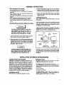
installing Wheels, Handle, Rubber Foot Strip
i
WARNIN_
!
THE WHEELS AND HANDLE OO NOT PROVIDE ADEQUATE CLEARANCE, $TABJLITY
OR SUPPORT FOR PULLING THE UNIT UP
AND DOWN STAIRS OR STEPS, THE UN[T
MUST I_ELtFT]_D, OR PUSHED UP A RAMP.
3- Rsmove the protectivepaper strip frOmth_ adhesive
backed rubber footstrip,Attachthe rubberfootstrip to
the bottom of 1he airtitnk leg. Press firmlyinto place°
4. Attach one wheel to each side of the air ¢omp_ssor.
Use one shoulder bott and one nut for each wheel,
Tighten securely.
Installing Regulator
Use a small amountof, pipe thread sealant on aJipipe
thread joints.
Install the regulatoron 1heend of lhe manifold using the
short pipe nipple. The arrow on the bottom ol the
regulatOrmust poi_ away from the manifold in order fo_
theregulatorto functionproperly,
_nstali the adapter and plugIn the regulator,,
The plug is
supplied with the regulator,Installthe rear cover and the
gauges at the same time, See diagram below,
1. Dipthe handle grip Insoapywater and sttdeintopositionas shownon photoon page 6 or page 12.
2, Attachthe handleto the insideofthecompressorsaddiebyp_jshtngthe handle In,unllithe slotin thehandle
engageswith the labs in the saddle, Pufithe handle
bsckar<l installthe two s<z_ws,one on each side of
the _e_ldte.Tighten securely,
R_ULATED
PRESSURE GAUG_
ittory be necemury to brace or support one
enU of the outfit when attaching the wheels
end the r_Jbber foot _trlp,
because the air
compressor will have a tenden=y to tip.
TANK
PRESSURE GAUGP-
tnstallthe control_over. Fasten It to the manifoldusing
the phillipsscrew. Installthe plasticmounting ring tothe
regulatorto fastenthe top ofthe contmtcover,See photo
on page 6.
INSTALLATION AND BREAK-IN PROCEDURES
Locationof the Air Compressor
Extension Cords
Loca4ethe air compressorin a ctean,dry end welJventilatecl area. The air filler must be kept clear o'l obstruc.
tlons which could reduce air delivery of the air
compressor.The air compressorshould be locatedat
least 12' away'from the wail or other obstructionsthat
wl!linterfere withtheftow of air. The air compressorhead
and shroudare designed to al!ow for propercooling.,If
humidity Is high a _ears air filter can be installed iD
remove excessive moisture. Follow the instructions
packaged with the air filter for proper installation,
Use extre,air hose insteaxJOf _n extensioncordto avoid
voltagedrop and power loss to the motor,
Lubrication
and Oil
Thtsunit n_eas no adcllttonal lubrication or otling
tf an axlet_slon cordmust t_ us'_, be sum it is:
. a 3-wire ext_._ion cord that h_ a _-,blade grounding
pll_, end !_3-_lotreceptacletigatwl!laccepttheplugon
the product,
. t_ good condition_
• no longerthan _50f_t.
.12 gtlUge (AWG) or larger. (Wire size increases as
gauge number _lecreaseso10 AWG and 8 AWG may
atso l_e used, OO NOT USt_ t4 or 16AWG_)
Grounding Instr,JcUons
L_
Ground
i
" Wire ""
IMPROPER GROUNDING CAN RESULT iN
ELECTRICAl. SHOCK. IN THE EVENT OF A
SHORT CIRCUIT, GROUNDING REDUCES
IHE RISK OF SHOCK BY PROVIDING AN
ESCAPE WIRE FOR THE ELECTRIC CURRENT. THIS AIR COMPRESSOR MUST BE
PROPERLYGROUNDED.
1. The air compressorts equippedwlth a cord having a
groundingwire with an _ppr_priate groundingplug.
The plug must be used with an outletthat has been
installedand groundedin accordance wi_h all IocaI
codes and ordinances, The out_et must have the
_aJ'_econfigurationas the plug. DO NOT USE AN
ADAPTER,
GROUNDING
L..------J
120 vOltS,i5 amps
Break-In PrOc_ums
2, Do not modify the plug 1hathas been provided.!! it
does not tit the available outlet, the correct outlet
shoutdbe installedby a qualifiederectrician
3 inspectthe plugand cordbeforeeach use_Do not use
ifthere are signsof damage,
,,2"
PIN
Serious damage moy _glt
If _I'KIfoll_ing
break-in tnatructrono =r== not closely
followed.
Thisprocedureis only _quir-ud the firstlime the=JrcompreSSOriS put intoserwce,
1. Set the
swlt_ OFFtAUTO lever to the'OFF'
poetriespressure
RISK OF ELECTRICAL SHOCK, IF REPAIRING OR REPLACING CORD OR PLUG, THE
GROUNDING WIRE MUST BE KEPT SEPARATE FROM THE CURRENT.CARRYING
WIRES, NEVER CONNECT THE GROUND,
tNG WIRE TO A FLAT BLADE PLUG TERMINAL (THE GROUNDING WIRE HAS
INSULATION WITH AN OUTER SURFACE
THAT IS GREEN - WiTH OR WITHOUT YELLOW STRIPES.)
if these grounding ine_ru_Uonsare not completely
unclerstood0
or if In doubtas to whether[he compressor
is properlygrounO_d,havethe install=ioncheckedby a
qualifiedelectrlclan_
2 Plug the.power c_ordinto the (;orrectbranc;h cimUit
receptacJe,
3 Turn the regulatorc!oc.kw'L_,e,,
openingit fulIy,to pre.
ventmr pressureI:_uz=o-up
=nthe tanK,
4_Move *,heOFF!AUTO leverto "AUTO'. Th_ compressor wltI starL
5, Run _he compressorfor 10 minutes, Make sure the
rupegulator
Is open and them is no tank pressure build- ,_
6 After 10 rnin.utes,_ose t,heregultttor by lurning it
counter-c_oc:Kwise,
f ne _urtankv_lIfill_ OJt-,outpressure and lhanthe rno_r Will510p
OPERATING PROCEDURES
1, Before attaching aJrhose or accessories, make sure
the OFFtAUTO lever is set to "OFF" and the air
regulatorIs closed (Close it by turningit counterClOCkWiSe)
COMPRESSED AIR FROM THE OUTFIT MAY
CONTAIN WATER CONDENSATION. DO
NOT SPRAY UNRLTERED AIR AT AN ITEM
Tl1AT GOULD B_ DAMAGED. SOM F AIR
OPERATED TOOLS OR DEVICES MAY
REQUIRE FILTERED AIR. READ THE
INSTRUCTIONS FOR THE AIR TOOL OR
DEVICE,
2_At_ch hOSe _ndaocessorfes.
WARNING
1"OOMUCH AIR PREgSURE CREATES A
HAZARDOUS
RISK
OF
BURSTING,
CARE-
FULLYFOLLOW STEPS 3 AND 5 EACH TIME
THE COMPRF-_SOR
IS USED.
.
Check the manufacturer'sm_lmum preserve_ating
for air tools and accessories, "Theregulatoroutlet
pressuremustnever exceed the maximurnprB_$ure
_at]ng.
4. TurntheOFF!AUTO le._r to "AUTO" and allow Tank
pressureto _,Jlld,Motorwill6too when tank presmure
reaches "Cut-out" pressure.
S Open theregulatorby turningit clockwise Adjustthe
regulatorto the correctpressuresettJng,Your compressor{=ready for use.
6. Alwaysoperale the air compressorIn well-ventilated
areas; free of gasoline or other solventvapors Do
notoperate the compressor near the spray area.
1t, Drain waterfrom air tank,
WATERWILL CONDENSE IN THE AIR TANK.
IF NOT DRAINED, WATER WILL CORRODE
AND WEAKEN THE AIR TANK CAUSING A
RISK OF AIR TANK RUPTURE.
With tank pressurest approximately20 psi,, open
the clan cock and allowmoisture to d_n.
, When you are finished:
7. Set the "OFF-AUTO"lever to "OFF",
8. Turntheregulatorcounter-clock.viseand set the out_
I_ pressuretO z_ro,
9oRemovetMeair toolor accessory,
! O. Open the ,'_egutator
and allow the air to slowlybleed
from the ta.,'P_Close the regulator when tank pres_
sumis approximately 20 psi.
NOTE
If drain cock valve Is p_ugged,release all air prossure.Tile valve can then be removed, cleaned,then
relnst=lled
!2o After thewater has been drained, olose the drsln
e.ock.The air compressorcan now be stored.
MAINTENANCE
UNIT CYCLES AUTOMATICALLY WHEN POWER IS ON. WHEN DOING MAIN_=.NANCE, YOU MAY
BE EXPOSED TO VOLTAGE SOURGESt COMPRESSED AIR OR MOVING PARTS. PERSONAL
INJURIES CAN OCCUR. BEFORE PERFORMING ANY MAINTENANCE 0 R REPAIR, UNPLUG THE
COMPRESSOR AND BLEED OFF ALL AIR PRESSURE,
Atr Filter-
Inspection
Safety Valve - Inspection
NOTE
Keep the airfilterclean at all times Do notoperate the compressorwith the air filter removed,
A dirty air filterwillnot a.llowthe compressorto operate
at furlcapacity°Beforeyou use the compressor,check
the air filter to be sum it is clean_
If it tsdirty, simplypullit out.You may wash it with a mild
detergent and warm water, or repiace It,
Check Valve- Replecement
1. Release afl air pressure fromaTr lanf< and unplug
outfit.
2. Remove shroud,
3, Loosen the top and bottom nuts and remove the
outlet tube.
4. Remove the pressurerelease tube and fitting,
5oUnsorew the chec_ valve (turn counterclockwise]
using a =ockel w_nch.
6 ChScK_at the valve _Isc moves treaty inside the
chiCk:valve and that the spring hOidSthe disc tn the
upper, €!o=_1 position. The check valve may be
cleaned with a solvent, such as paint and varnish
remover,
% Apply aQeJentto the check valve threeels Reinstall
the oPm¢_y=lvo(turn _lockwioe),
8, Replace the pressure release tube and fittfng.
9, Replaoe the outlet t',,=_)e
€,ndtightenlop end bottom
nu_s.
!0, Rep!_ce the 6hrOUd_
IF THE SAFETY VALVE DOES NOT WORK
PROPERLY, OVER-PRESSURIZATION MAY
OCCUR, GAUSING AIR TANt_ RUFrTUREOR
AN EXPLOSION. OCCASIONALLY PULL
THE RING ON THE SAFETY VALVE 1"O
MAKE SURE THAT THE SAFETY VALVE
OPERATES FREELY. IF THE VALVE iS
STUCK
OR DOES NOT OPERATE
SMOOTHLY, IT MUST BE REPLACED WITH
THE SAME TYPE OF VALVE.
Motor
The mow has an automaticreset thermal overloadWotenor. Hthe motor overheats for any reason, the overioa_ i)rot=_or will shut Offthe motor. The _
must be
allowed to ¢ool€lownbeforerestarting,The comFessor
•willautoma.ticallyre-start after the motor oools,
If the overtoadprotectorshuts the motor off kecluently,
d_ci( for a possible voltageproblem, Low vOltagecan
also be suspectedwhen:
t., _e motor aoe_ not get up to full power
or speed;
2_fuses blow out when starlingthe motor;,lights dim and
remaindim when motor is started and is running.
STORAGE
Beforeyou store the air compressor,make sure you do
the foflowlng:
2. Protectthe etectficaJ cord and air hose from damage
(such s8 _:>etOg
stepped on or _n over). Wind them
loosely amUr_l_
the compressorhandle,
1, Reviewthe 'Maintsr_n_e" section on the precaeding
pages and perform maintenan;e as necessary, Be
sure to drain w=ter fromthe air la_k.
Store _he air compressorin a clean and dry IocaUon.
TROUBLESHOOTING
GUIDE
PERFORMING REPAIRS MAY EXPOSE VOLTAGE SOURCES_ MOVING PARTS, OR COMPRESSED AIR SOURCES. PERSONAL INJURY MAY OCCUR. PRIOR TO ATTEMPTING ANY
REPAIRS UNPLUG THE AIR COMPRESSOR AND BLEED OFF TANK AIR PRESSURE.
PR0.u .
...... cause
............................CORR T .
Ex_essk,e _r_ pressure
safety valve Pol_soff,
Pressureswitchdoesnot shut olt"
motor when compressorreaches
"cut-oUt"pressure,
Move the pressure
switohlever
to_e "OFF'I Po_ilion. if the OUtfitdoesn 1 shut off, an_lthe eleotricai
conlactsare welc_edtogether,replacethepressure
switch.
II the contactsam good, checkto see if the pin in
thebottomofthe pressure relays valve ts stucK,if
it does not move freely,apace the vetve
Pressure switch "cut-out"
high,ui, , .i. ,.,
, ...............................
tao
Returnttleputfitto Sears ServleeCente_to check
anti aclju=,or replace switch,
Air leaks at fittings
Tubafiffingsare not_ht enough.
Tighten fittingswl_re air can be he_a_esCaping_-_
Ohec!_fittings with soapy water solution,, DO NOT
OV ER-TIGHTEN,
Air leaks at checkvalve.
Defective or dirty check valve.
A defective check valve resultsIn a constant air
reel<at the pressure release valve when there is
pressureIn thetankand the com_esaor is shut off.
Remove and clean or replace check valve DO
NOT OVER-TIGHTEN.
Airl@ak,_at pressure
_ltoh release
valve
Defective pressure_witch
rolease valve.
Remove end replace the release
valve..
Defective ch_;k v=lve,
A defective CHECK valve resultsin e constant_ir
leak at t_ pressure relgase valve when there i_
pressurein thetank_nc_thecompressor isshut off.
Remove and clean or replace check valve. DO
NOT OVER-TiGHTEN,
Dofecttve air tank,
AJrtank must be replaced Do not repair tt_:leakl
Airleak_ in air tank_
i w.,.,.o
....
I
DO NOT DRILL INTO_ WELD, OR
OTHERWISE MODIFY AIR TANK OR tT
WILL WEAKEN,
Air leaks betweenhead and
va_ #_te.
Leaking gasket.
Pre=_ure reading on _he
regulated pressure gauge
dropswhen _n a_c_sory Is
used.
It IS normal for "some" pressure
drop to occur°
m
Torquehead screwsto 8 It, Ibs, It this does notstop
leak replace gasket
If t_ere is an excessive amountof pressure drop
when the _essory is usecl,adjust _he regulator
following 1heinstructionson pg. 6.,
Note
Adjust tt_eregulated pressure under flow
conditibns (while a_cessory is being
use_,)
0
..........
TROUBLESHOOTING GUIDE (Continued)
PROBLEM
CAUSE
CORRECTION
Air leak fror_S_,fety Valve
Possibledefect in Salety Valve.
(_rate safety valvemanuaJlyby pulting on dngoif
vaJvestill ieaks, it shouldbe re_laced.
KnockingN_ise
Defective Check Valves.
i_move and clean or repl_ce.
v_,,,,,,,
,_,,,,,,_
Compressorisnotsupplyingenough airtooperate
_ocessorl_s,
Molor Wllt Not Rurl
-.
,
,
.....
Prolongedexcessive use of air.
0ecrease amount of air usage.
Compressor is not large enough
for air requirement.
Check the accessoryair requimmerd.If it is higher
than the SCFM or pressure supplied by your a_r
compressor, you need a _argercompressor.
Restrictedair intake filter.
Cleanor replaceair intakefiller, Do nc_operateIhe
air compressorin lhe paint spray area.
Holetn hose.
Check and replace if required,
Cheek Valve restricted.,
Remove snd clean or r_place,.
Air leaks.
....
Motor overloadprotectionswitch
has tripped°
Tighten fittings, (See Air Leaks Section of
_ubleshooting Guide.)
Lit motorcoo! off and overloads_tch wtft auton',atlcsllyreseL
Tank pressure exceeds pressure
_witch "cut-in" pressure,
Motor will start automatlc_Jiywhen tank 1oreseure
drops below °'cut-in" pressureof pressureswilch.
Wrong gauge wire or length of
extensioncord,
Che¢_ forproper gauge wire and cord length,
Check Valvestuck open.
Remove and clea.n or replace_
Loose electrical connecltonso
Check wiring connection inside pressure switch
and terminal box area.
Possibledefective capacitor,
Return to Sears Service Centertor ir.spectionor
replacement if necessary,
Paint spray on internal
parts.
Have check,L_ at Sears Service Center. Do not
operate the compressorin the paint spray area,
Si_eflammable vapor wartungon p_ge 3.
Possible defective motor,
Have checked at a Ioce_Sears Servlce Center.
Fuse blown,
tripped,
t._Che_kfuse box _r btownfuse randreplace if
necessary. Re-set circuitbreaker°Oo not use a
fuse or circuitl:_aker with higherr_tJngthan that
s;)eotfied for your particularbranch circUlL
circuit
motor
breaker
2. Check for proper fuse: only 'Fusetren" type T
fuses are acceptable,
3, Check for low voltageconditionsandtor proper
extensioncord.
4,Disoonnecl the other elec_icaiappliancesfrom
ctmult or operate theoompessoron itsown branch
cir_uiL
R_guiator knob - con|inuOUSsir leak,, Regulator wltl
not shut-offat air outlet.
Pressurerelease vatve on _res.
sure switch has no1 unloaded
I_ea0pressure,
Bleed the fineby pushingthe leveron thepressure
switch to the "Off" position;if the vaive does not
open, replace it
Dirty or damaged re_ju_a_or
internal p_,rts,
Cle_n or r_ptace regulator, or internal parts.
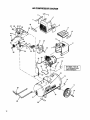
AIR COMPRESSOR DIAGRAM
t
44
X
45
4
46 47
42
25
33
32
23
18
21
22
12
2O
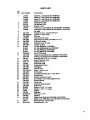
PARTS LIST
KEY
NO.
2
3
4
5
6
7
B
9
10
11
12
13
14
15
PART MUMBER
LA-1976
LA-1979
LA.2035
LA4_;7
LA-IB_'7
LAd779
CAC.33t._
LA-1975
LA-2035
CAC-107;)
5SF-0129-ZN
CAC-1080
LA.1994,1
CAG.I062
CAC-1099
SSF-S05
CA,C-1098
TA-4136
TA-4135
TA.4140
16
17
18
19
20
21
22
?.3
24
26
26
27
28
29
3O
31
32
33
34
35
38
37
3S
S9
4O
41
42
TA-4139
STD541437
CAC,4293
CAC-4313
CAC-60
LA-1610-1
SUDL-B-1
LA-1gT8
CAC-1087
CAC.1086
CAC-334
SSF-t318-ZN
CAC,4290
SSP-7513
CAC-333-1
BSN-8001
SSP.71;21
CAC-1120
CAG-f083
C-GA,344
CAC-1084
SS-20"t2
88.2071
H-Z0S9
CAC-487
SS-3_-CD
CAC.36S
TIA-4-325
TIA-412S
CAC,61
8UDL-403-1
DESCRIPTION
Model No. Label (Model No. 919.154120)
Model No, Label (Model No, 91B,_4020)
Model No. Label (Model No. 9t9,_4320)
Model No, Label (Model No. 919,154420)
Maintenance Label
Hot Surfsoe Label
9kroud - front
Performan=e Label (Model No, _19.154120& 919.154020)
Performance Label (Model NO, _9.1S4320 & 919.1544:_0)
Not USed
Braolmt (2 ueed - included with _€11)
I,ooknut '/4"-20 (2 used)
Tool troy
Advanoad toch. Label
Rear ahrou_ assembJy (include_ 2 ea. #7)
U-Channel isolator
Shoulder screw (2 used)
Isolator (2 used)
Air Tank (Model No. 919.154020) i
Air "lllnkASME (Model No. 919,1r_4120)
Air Tank (Model No. 919.154320)
Air Tank (Mod_l NO. 919.154420)
Nut _/o"-16(2 u=ed)
Wheel (2 used) (Model No. 919,11_4020
& 919.154120)
Wheel (z u_d) (,Model N_. e_e.l_20 s _g._4420)
Shoulder bolt ¾ -tB × 21/= (2 ut_.)
Beam Craftsman Label
Rubber foot strip
Dmln Tank Label
Handle (black firdah)
Handlegrip
Control cover
Sorew - onntrol oaver
Check valve
Nut sleeve assembly (for %" O,D_,Tube)
Shroud Plate
RMchet Fastener (2 used)
Nut (Tighten until it SlOps against head)
Silicone Sleeve
Outlet tube
Pmuure Gauge (2 used)
Rear cover
Nipple (%" NPT × 1Vd° tong)
Nipple (_/,"NPT× 1W' tong)
Adapter
Regulator
PIp_ plug T/_,NPT
Mtmlfold
SMIty valve {Model No. 919.1540;Z0& 919.154320)
Safety valve ASME (Model No. 9t9.164120 & 919,154420)
Mounting Ring- control cover
Cord assembly- line
13
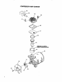
COMPRESSOR PUMP DIAGRAM
56
58
59
60
6t
62
63
ft
___
__,/64
M_K
TOWARDS MOTOR,
65
PARTS LIST
KEY
NO.
43
44
45
46
47
48
49
SO
51
52
53
64
55
S6
57
S8
Sg
60
61
62
_,e3
U'64
65
68
67
68
69
70
PARTNUMBER
DESCRIPTION
CAC-4220-1
LA.153t-1
CAC-1085
STDSTS0";r_5
STDS75026
SSP-9013
LAo!535
88P.6088
CAC-4215-t
5SW-7367
KK.4315
SSF-961
CAC-260-2
CAC-t046
SSF-990
CAG-1067
SSF-6640
CA(;-1066
CAC-4281
SSG-8166
€-MO-3006
CAC-4303
SSF.2043
CAG-1055
SSF-3101
88T302S
H-5796
9-16269
Sl-30-08-4-B
Key S3 & 64 Car, only be
Pressure switch
On-Otf Labol
Pressure relief tuba (wurmltube before installing on #50,)
Nut (for !/4"O,D, Tube)
Farrulo (fOr ',_"O,D, Tube)
Tube insert
Warning Label
Barbed fitting
Cord assembly- motor
Stz,atn roller (2 used)
Pressure release valve mn_ mounting nut (included with #43)
Screw I/_,0
AB x oI4_long (2 zINd)
Air Filter
intake muffler
SCrew 1/4"- 20 × 1t/4- (2 used, torque 7-10 it° lbs.)
Head
Stud V4"-20× 11/..' (2 used, _rque 7-10 ft. Ibs°)
Gasket
Y_lVe plate ass4tmbly(inedddU vaJVes,rostrlctore,& screws)
O-ring
Connecting rod assembly (torque screw 30.,35 In. Ibs.)
Cylinder slsmve(position 10_etlng mark townrds motor)
Motor 2 HP
Eccentric/Bearing Assyo(In_ludai I ca, #70)
Screw (eccentric, torque 50.60 in. Ibs.)
Fen
Screw #10-24 × _/." long (torque 30.35 in. Ibs.)
Bearing (eccentric)
NOT ILLUSTRATED
Air Hose assembly (_/_"l.D._ 15')
Air Chuok
Ownare Manuel
purcJ18_hdampart of KK-4_t e-_onnectlngrod kit
15
SL A/RS
OWNERS
MANUAL
SERVICE
MODEL NO.
919.154020
9!9.154120
919.154320
919.154420
HOW TO ORDER
REPAIR PARTS
CRAFTSMAN
PERMANENTS,( LUBRICATED
AIR COMPRESSOR
Now "hat you have purchasedyo)JrSears Air Compressor shoulda
need ever e0dstfor repair part_ oi service sirt_ptycontaot any Sears
Service Center and mast Sears Floebuckand Co stores Be sure
to provideall pertinent ta_ whe_lyou catl or visit
The modet number of your Se=sfAir Compressor is 919
This number Dartbe found on thei|_l:)e] WhiChfs IOOaledOnbe back
Offhe shroud
.............
-_
,
WHEN ORDERING REPAIR PAR_S ALWAYS GIVE THE
FOLLOWING INFORMATION:
PART NUMBER
, MODEL NUMBER
IPART DESCRIPTION
INAME OF ITEM
All parts listed may be ordered fm_nany Sears Service Center and
mosl Sears _tores
Iflhe parts you need am not stork_d looa|ly your orderw/!l be elnc
ironicallytransmitted to a 8eat_ R_paJrParts DistributionCenl_t for
handllng
Sears,
$1 _lF084 9
10till
Roebuck
and Co., _hlcago,
IL 60684
U.S.A.
p'tin_di_U.S.A.