1
service.book Page i Wednesday, December 18, 2002 8:35 AM
Service Guide
Publication Number 54622-97037
December 2002
For Safety Information, Warranties, and Regulatory information, see the pages
at the end of this book.
©
Copyright Agilent Technologies 2000, 2002
All Rights Reserved
Agilent 54621A/22A/24A
Oscilloscope and
Agilent 54621D/22D
Mixed-Signal Oscilloscope
service.book Page ii Wednesday, December 18, 2002 8:35 AM
The Oscilloscope At a Glance
Choose from a variety of oscilloscopes for capturing
long, non-repeating signals
with 200 MSa/s sample rate and 2 MBytes of
MegaZoom deep memory per channel.
• Agilent 54621A - 2-channel, 60-MHz bandwidth
• Agilent 54621D - 2-channel +16 logic channels, 60MHz bandwidth
• Agilent 54622A - 2-channel, 100-MHz bandwidth
• Agilent 54622D - 2-channel +16 logic channels,
100-MHz bandwidth
• Agilent 54624A - 4-channel, 100-MHz bandwidth
Display shows current input signals
• All analog and digital (54621D/22D) channels
displayed in main and delayed mode
• Indicators for channel, time base, digital (54621D/
22D) channel activity, trigger and acquisition
status
• Softkey labels
• Measurement results
Digital channel controls select, position, and label
inputs (54621D/22D)
• Turn channels on or off individually or in groups
of 8
• Rearrange order of channels to group related
signals
• Create and display labels to identify channels
Run control keys begin and end data acquisition
• Run/Stop starts and stops continuous
acquisitions
• Single performs one acquisition
• Infinite persistence accumulates and displays the
results of multiple acquisitions
Horizontal Controls select sweep speed and delay
parameters
• Sweep speeds from 5 ns/div to 50 ns/div
• Delay control moves waveform display to point of
interest
• Delayed mode and delay allow zooming in to show
a portion of waveform in detail (split screen)
ii
Trigger keys define what data the oscilloscope will
trigger on
• Source key allows conventional oscilloscope
triggering
• Modes include Edge, Pulse Width, Pattern, CAN,
Duration, I2C, LIN, Sequence, SPI, TV, and USB
triggering
General controls measure, save and restore results,
and configure the oscilloscope
• Waveform math including FFT, subtract, multiply,
integrate, and differentiate
• Use Quick Meas to make automatic
measurements Integrated counter included with
Quick Meas.
• Use cursors to make manual measurements
• Save or recall measurement configurations or
previous results
• Autoscale performs simple one-button setup of
the oscilloscope
Softkeys extend the functionality of command keys
Select measurement types, operating modes, trigger
specifications, label data, and more
Digital channel inputs through a flexible probing
system (54621D/22D)
• Sixteen channels through a dual 8-channel cable
with micro-clips
• Set logic levels as TTL, CMOS, ECL, or to a userdefinable voltage
Utilities
• Dedicated parallel printer port, controller
operation, floppy disk storage
Built in Quick Help system
• Press and hold any key front-panel key or softkey
to get help in 11 languages.
service.book Page iii Wednesday, December 18, 2002 8:35 AM
In This Book
This book provides the service information for the Agilent 54621A/22A/24A
Oscilloscope and the Agilent 54621D/22D Mixed-Signal Oscilloscope.
This manual is divided into these chapters:
Chapter 1 provides general information and specifications.
Chapter 2 shows you how to prepare the oscilloscope for use.
Chapter 3 gives performance tests.
Chapter 4 covers calibration and adjustment procedures.
Chapter 5 provides troubleshooting information.
Chapter 6 gives the procedures and techniques for replacing assemblies and
other parts.
Chapter 7 includes a list of replaceable parts, part ordering information, and
shipping information.
At the back of the book you will find Safety information, Warranties, and
Regulatory information.
iii
service.book Page iv Wednesday, December 18, 2002 8:35 AM
iv
service.book Page 1 Wednesday, December 18, 2002 8:35 AM
Contents
1 General Information
To inspect package contents 1-3
To inspect options and accessories
Performance Characteristics 1-9
1-6
2 Preparing the Oscilloscope for Use
Setting up the Oscilloscope
2-3
To adjust the handle 2-4
To power-on the oscilloscope 2-5
To adjust the display intensity 2-6
To connect the oscilloscope probes 2-7
To compensate your probe 2-7
To use the digital probes (mixed-signal oscilloscope only)
To connect a printer 2-12
To connect an RS-232 cable 2-12
To verify basic oscilloscope operation 2-13
Getting started using the oscilloscope interface
Using Quick Help
2-8
2-14
2-16
Selecting a language for Quick Help when the oscilloscope starts up 2-16
Selecting a language for Quick Help after you have been operating the
oscilloscope 2-17
Loading a language from floppy disk 2-18
Cleaning the oscilloscope
2-19
3 Testing Performance
List of Test Equipment 3-3
To construct the test connector 3-4
To test the 54621D/22D Oscilloscope digital channels 3-5
To verify threshold accuracy 3-6
To verify voltage measurement accuracy 3-10
To verify bandwidth 3-13
To verify horizontal Dt and 1/Dt accuracy 3-15
To verify trigger sensitivity 3-17
Agilent 54622A/22D/24A Performance Test Record 3-20
Agilent 54621A/21D Performance Test Record 3-21
Contents-1
service.book Page 2 Wednesday, December 18, 2002 8:35 AM
Contents
4 Calibrating and Adjusting
To adjust the power supply 4-4
To perform User Cal 4-7
To adjust the oscilloscope display
4-8
5 Troubleshooting
Solving General Problems with the Oscilloscopes
If there is no trace display 5-3
If the trace display is unusual or unexpected
If you cannot see a channel 5-5
Troubleshooting the Oscilloscope
5-4
5-6
To construct your own dummy load 5-7
To check out the oscilloscope 5-8
To check the Low Voltage Power Supply 5-11
To run the internal self-tests 5-13
6 Replacing Assemblies
To remove the cabinet 6-4
To remove the fan 6-5
To remove the floppy drive 6-6
To remove the front panel 6-7
To remove the display 6-8
To remove the system board 6-10
To remove the power supply 6-12
To remove the keyboard assembly 6-15
To remove the handle 6-16
7 Replaceable Parts
To order a replacement part
Contents-2
7-3
5-3
service.book Page 1 Wednesday, December 18, 2002 8:35 AM
1
General Information
service.book Page 2 Wednesday, December 18, 2002 8:35 AM
General Information
This chapter lists general information for the Agilent 54620-series
Oscilloscopes. It also includes performance characteristics and
specifications for the oscilloscopes.
1-2
service.book Page 3 Wednesday, December 18, 2002 8:35 AM
General Information
To inspect package contents
❏ Inspect the shipping container for damage.
If your shipping container appears to be damaged, keep the shipping container
or cushioning material until you have inspected the contents of the shipment
for completeness and have checked the oscilloscope mechanically and
electrically.
❏ Verify that you received the following items and any optional accessories in
the oscilloscope packaging (see figure following).
• 54620-Series Oscilloscope (54621A, 21D, 22A, 22D, or 24A)
• 10074C 10:1 150 MHz passive probes with ID:
(2) for 54621A, 21D, 22A, or 22D oscilloscopes
(4) for 54624A oscilloscope
• 54620-68701 digital probe kit (for 54621D or 22D)
• Accessory pouch and front-panel cover (standard for 54622A, 22D, and 24A)
(optional on 54621A and 21D; order N2726A)
• Power cord (see table 1-3)
• IntuiLink for 54600-series Oscilloscopes software and RS-232 cable (for
54622A, 22D, or 24A).
IntuiLink is a Windows application that makes it very easy for you to
download images, waveform data, or oscilloscope setups from the
oscilloscope to your pc using either Microsoft Word or Microsoft Excel. After
installation of IntuiLink, a tool bar in these Microsoft applications will make
connection and data transfer from the oscilloscope very simple.
IntuiLink software is available free on the web at:
www.agilent.com/find/5462xsw
RS-232 cable may be ordered separately, part number 34398A
If anything is missing, contact your nearest Agilent Sales Office. If the shipment
was damaged, contact the carrier, then contact the nearest Agilent Sales Office.
1-3
service.book Page 4 Wednesday, December 18, 2002 8:35 AM
General Information
• Agilent IntuiLink Data Capture (for 54622A, 22D, or 24A)
IntuiLink Data Capture is a standalone program for downloading waveform
data from the oscilloscopes to your PC via GPIB or RS-232 interface. It
provides the capability to transfer deep memory data out of the oscilloscope,
allowing up to 4MB (scope channels) and 8MB (logic channels). The
IntuiLink for 54600-Series limits the size of acquisition data available to a
maximum of 2,000 points regardless of actual number of acquisition points
on the screen. With the IntuiLink Data Capture, the amount of points
transferred will be the actual number of acquisition points currently
displayed or you may select the number of points to download. It provides
the following functionality:
• Download waveform data and display the data as a simple chart
• Save the data as binary or text files
• Copy the chart and a selected portion of the data to the clipboard. The
maximum data saved to the clipboard is 50,000 point
• Load saved waveform data back into the application
IntuiLink Data Capture software is available free on the web at:
www.agilent.com/find/5462xsw
RS-232 cable may be ordered separately, part number 34398A
❏ Inspect the oscilloscope
• If there is mechanical damage or a defect, or if the oscilloscope does not
operate properly or does not pass the performance tests listed in the Service
Guide, notify your Agilent Sales Office.
• If the shipping container is damaged, or the cushioning materials show signs
of stress, notify the carrier and your Agilent Sales Office. Keep the shipping
materials for the carrier’s inspection. The Agilent Sales Office will arrange
for repair or replacement at Agilent’s option, without waiting for claim
settlement.
1-4
service.book Page 5 Wednesday, December 18, 2002 8:35 AM
General Information
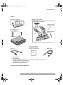
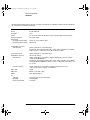
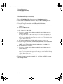
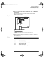
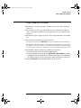
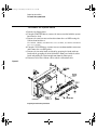
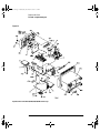
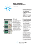
Figure 1-1
54620-Series Oscilloscope
54620-68701 digital probe kit*
54620-61801 16-channel cable***
5959-9334 2” Probe
ground lead (qty 5)
Accessories pouch and
front-panel cover**
Power cord
5090-4833 Grabber
(qty 20)
IntuiLink for 54600-series
software, Data Capture
software and serial cable**
10074C Probes
s
s1
* 54621D /22D only
** 54622A/22D/24A only
*** The following additional replacement parts (not included) are available for the digital cable:
5959-9333 replacement probe leads (qty 5)
5959-9335 replacement pod grounds (qty 5)
01650-94309 package of probe labels
Package contents for 54620-Series Oscilloscopes
1-5
service.book Page 6 Wednesday, December 18, 2002 8:35 AM
General Information
To inspect options and accessories
❏ Verify that you received the options and accessories you ordered and that none
were damaged.
If anything is missing, contact your nearest Agilent Sales Office. If the shipment
was damaged, or the cushioning materials show signs of stress, notify the carrier
and your Agilent Sales Office.
Some of the options and accessories available for the 54620-Series Oscilloscopes
are listed in tables 1-1 am 1-2. Contact your Agilent Sales Office for a complete
list of options and accessories.
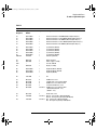
Table 1-1
Options available
Option
Description
003
Shielding Option for use in severe environments or with sensitive devices under
test–shields both ways (in and out):
RS-03 magnetic interface shielding added to CRT, and
RE-02 display shield added to CRT to reduce radiated interference.
1CM
Rackmount kit (same as Agilent 1186A)
A6J
ANSI Z540 compliant calibration service
See table 1-3 for power cord options
1-6
service.book Page 7 Wednesday, December 18, 2002 8:35 AM
General Information
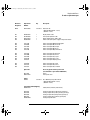
Table 1-2
Accessories available
Model
Description
01650-61607
16:16 logic cable and terminator (for use with 54621D/22D)
54620-68701
16:2 x 8 logic input probe assembly (shipped standard with 54621D/22D)
1146A
100 kHz current probe, ac/dc
1183A
Testmobile scope cart
1185A
Carrying case
1186A
Rackmount kit
10070C
1:1 passive probe with ID
10072A
Fine-pitch probe kit
10073C
10:1 500 MHz probe with ID
10075A
0.5 mm IC clip kit
10076A
100:1, 4 kV 250 MHz probe with ID
10100C
50Ω termination
10833A
GPIB cable, 1 m long
34398A
RS-232 cable (standard with 100 MHz models)
E2613B
0.5 mm Wedge probe adapter, 3-signal, qty 2
E2614A
0.5 mm Wedge probe adapter, 8-signal, qty 1
E2615B
0.65 mm Wedge probe adapter, 3-signal, qty 2
E2616A
0.65 mm Wedge probe adapter, 8-signal, qty 1
E2643A
0.5 mm Wedge probe adapter, 16-signal, qty 1
E2644A
0.65 mm Wedge probe adapter, 16-signal, qty 1
N2726A
Accessory pouch and front-panel cover (standard with 100 MHz models)
N2727A
Thermal printer and pouch
N2728A
10 rolls of thermal printer paper
N2757A
GPIB Interface Module
N2758A
CAN Trigger Module
N2771A
1000:1, 15 kV, 50 MHz high voltage probe
N2772A
20 MHz differential probe
N2773A
Differential probe power supply
N2774A
50 MHz current probe, ac/dc
N2775A
Power supply for N2774A
1-7
service.book Page 8 Wednesday, December 18, 2002 8:35 AM
General Information
Table 1-3. Power Cords
Plug Type
Cable Part Number
Plug Type
Cable Part Number
Opt 900 (U.K.)
8120-1703
Opt 918 (Japan)
8120-4754
Opt 901 (Australia)
8120-0696
Opt 919 (Israel)
8120-6799
Opt 902 (Europe)
8120-1692
Opt 920 (Argentina)
8120-6871
Opt 903 (U.S.A.)
8120-1521
Opt 921 (Chile)
8120-6979
Opt 906 (Switzerland)
8120-2296
Opt 922 (China)
8120-8377
Opt 912 (Denmark)
8120-2957
Opt 927 (Thailand)
8120-8871
Opt 917 (Africa)
8120-4600
1-8
service.book Page 9 Wednesday, December 18, 2002 8:35 AM
General Information
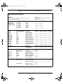
Acquisition: Analog Channels
Performance Characteristics
* Denotes Warranted Specifications, all others are typical. Specifications are valid after a 30-minute warm-up period and
±10 °C from firmware calibration temperature.
Acquisition: Analog Channels
Max Sample rate
Max Memory Depth
Vertical Resolution
Peak Detection
Averages
High Resolution Mode
Filter:
200 MSa/s
4 MB interleaved, 2 MB each channel
8 bits
5 ns
selectable from 2, 4, 8, 16, 32, 64 ...to 16383
12 bits of resolution when ≥500 us/div, average mode with average = 1
Sinx/x interpolation (single shot BW = sample rate/4 or bandwidth of scope, whichever
is less) with vectors on.
Acquisition: Digital Channels (on 54621D and 54622D only)
Max Sample Rate
400 MSa/s
Max Memory Depth
8 MB
Vertical Resolution
1 bit
Glitch Detection (min pulse width) 5 ns
1-9
service.book Page 10 Wednesday, December 18, 2002 8:35 AM
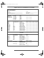
General Information
Vertical System: Analog Channels
* Denotes Warranted Specifications, all others are typical. Specifications are valid after a 30-minute warm-up period and
±10 °C from firmware calibration temperature.
Vertical System: Analog Channels
Analog channels
Bandwidth (-3dB)*
ac coupled
Calculated rise time
(= 0.35/bandwidth)
Single Shot Bandwidth
Range1
Maximum Input
Offset Range
Dynamic Range
Input Resistance
Input Capacitance
Coupling
BW Limit
Channel-to-Channel Isolation
(with channels at same V/div)
Probes
Probe ID (Agilent/HP &
Tek Compatible)
1
54621A/21D, 54622A/22D: Ch1 and 2 simultaneous acquisition
54624A: Ch 1, 2, 3, and 4 simultaneous acquisition
54621A/22D: dc to 60 MHz
54622A/22D/24A: dc to 100 MHz
54621A/21D: 3.5 Hz to 60 MHz
54622A/22D/24A: 3.5 Hz to 100 MHz
54621A/22D: ~5.8 ns
54622A/22D/24A: ~3.5 ns
50 MHz
1 mV/div to 5 V/div
CAT I 300 Vrms, 400 Vpk
CAT II 100 Vrms, 400 Vpk
with 10074C 10:1 probe: CAT I 500 Vpk, CAT II 400 Vpk
±5 V on ranges <10 mV/div
±25 V on ranges 10 mV/div to 199 mV/div
±100 V on ranges ≥200 mV/div
Lesser of ±8 div or ±32 V
1 MΩ ±1%
~ 14 pF
ac, dc, ground
~ 20 MHz selectable
dc to 20 MHz > 40 dB
20 MHz to max bandwidth > 30 dB
10:1 10074C shipped standard for each analog channel
Auto probe sense
1 mV/div is a magnification of 2 mV/div setting. For vertical accuracy calculations, use full scale of 16 mV for 1 mV/div sensitivity setting.
1-10
service.book Page 11 Wednesday, December 18, 2002 8:35 AM
General Information
Vertical System: Analog Channels (continued)
* Denotes Warranted Specifications, all others are typical. Specifications are valid after a 30-minute warm-up period and
±10 °C from firmware calibration temperature.
Vertical System: Analog Channels (continued)
ESD Tolerance
Noise Peak-to-Peak
Common Mode Rejection Ratio
DC Vertical Gain Accuracy*1
DC Vertical Offset Accuracy
Single Cursor Accuracy1
Dual Cursor Accuracy*1
1
±2 kV
2% full scale or 1 mV, whichever is greater
20 dB @ 50 MHz
±2.0% full scale
< 200 mV/div: ±0.1 div ±1.0 mV ±0.5% offset
≥200 mV/div: ±0.1 div ±1.0 mV ±1.5% offset value
±{DC Vertical Gain Accuracy + DC Vertical Offset
Accuracy + 0.2% full scale (~1/2 LSB) }
Example: For 50 mV signal, scope set to 10 mV/div (80 mV full scale), 5 mV offset,
accuracy = ±{2.0%(80mV) + 0.1 (10 mV) + 1.0 mV + 0.5% (5 mV) + 0.2%(80 mV)} = ± 3.78 mV
±{DC Vertical Gain Accuracy + 0.4% full scale (~1 LSB)}
Example: For 50 mV signal, scope set to 10 mV/div (80 mV full scale), 5 mV offset,
accuracy = ±{2.0%(80 mV) + 0.4%(80 mV)} = ±1.92 mV
1 mV/div is a magnification of 2 mV/div setting. For vertical accuracy calculations, use full scale of 16 mV for 1 mV/div sensitivity setting.
Vertical System: Digital Channels (54621D and 54622D only)
Number of Channels
Threshold Groupings
Threshold Selections
User-Defined Threshold Range
Maximum Input
Voltage
Threshold Accuracy*
Input Dynamic Range
Minimum Input Voltage Swing
Input Capacitance
Input Resistance
Channel-to-Channel Skew
16 Digital – labeled D15 – D0
Pod 1: D7 - D0
Pod 2: D15 - D8
TTL, CMOS, ECL, user-definable (selectable by pod)
±8.0 V in 10 mV increments
±40 V peak CAT I
±(100 mV + 3% of threshold setting)
±10 V about threshold
500 mV peak-to-peak
~ 8 pF
100 kΩ ±2% at probe tip
2 ns typical, 3 ns maximum
1-11
service.book Page 12 Wednesday, December 18, 2002 8:35 AM
General Information
Horizontal
* Denotes Warranted Specifications, all others are typical. Specifications are valid after a 30-minute warm-up period and
±10 °C from firmware calibration temperature.
Horizontal
Range
Resolution
Vernier
Reference Positions
Delay Range
Pre-trigger (negative delay)
Post-trigger (positive delay)
Analog Delta-t Accuracy
Same Channel*
5 ns/div to 50 s/div
25 ps
1-2-5 increments when off, 25 minor increments between major settings when on
Left, Center, Right
Greater of 1 screen width or 10 ms
500 seconds
±0.01% reading ±0.1% screen width ±40 ps
Example: for signal with pulse width of 10 us, scope set to 5 us/div (50 us screen width),
delta-t accuracy = ±{.01%(10 us) + 0.1% (50 us) + 40 ps} = 51.04 ns
Channel-to-Channel
Digital Delta-t Accuracy
Same Channel
±0.01% reading ±0.1% screen width ±80 ps
(non-Vernier settings)
±0.01% reading ±0.1% screen width ±(1 digital sample period, 2.5 or 5 ns based on
sample rate of 200/400 MSa/s)
Example: for signal with pulse width of 10 us, scope set to 5 us/div (50 us screen width),
and single pod active (400 MSa/s), delta-t accuracy = ±{.01%(10 us) + 0.1% (50 us) + 2.5
ns} = 53.5 ns
Channel-to-Channel
±0.01% reading ±0.1% screen width ±(1 digital sample period, 2.5 or 5 ns)
±chan-to-chan skew (2 ns typical, 3 ns maximum)
10 ppm
0.025% screen width + 30 ps
Main, Delayed, Roll, XY
Delay Jitter
RMS Jitter
Modes
XY
Z blanking
Bandwidth
Phase error @ 1 MHz
1.4 V blanks trace (use External trigger)
Max bandwidth
1.8 degrees
1-12
service.book Page 13 Wednesday, December 18, 2002 8:35 AM
General Information
Trigger System
* Denotes Warranted Specifications, all others are typical. Specifications are valid after a 30-minute warm-up period and
±10 °C from firmware calibration temperature.
Trigger System
Sources:
Modes
Holdoff Time
Selections
Edge
Pattern
Pulse Width
CAN
Duration
I 2C
LIN
Sequence
SPI
USB
TV
Autoscale
54621A/22A: Ch 1, 2, line, ext
54621D/22D: Ch 1, 2, line, ext, D15 - D0
54624A: Ch 1, 2, 3, 4, line, ext
Auto, Auto level, Triggered (normal), Single
~60 ns to 10 seconds
Edge, Pattern, Pulse Width, CAN, Duration, I2C, Sequence, SPI, TV, USB
Trigger on a rising or falling edge of any source.
Trigger on a pattern of high, low, and don’t care levels and a rising or falling edge
established across any of the sources. The analog channel’s high or low level is defined
by that channel’s trigger level.
Trigger when a positive- or negative-going pulse is less than, greater than, or within a
specified range on any of the source channels.
Minimum pulse width setting: 5 ns
Maximum pulse width setting: 10 s
Trigger on CAN (Controller Area Network) version 2.0A and 2.0B signals. It can trigger
on the Start of Frame bit of a data frame, a remote transfer request frame, or an overload
frame.
Trigger on a multi-channel pattern whose time duration is less than a value, greater
than a value, greater than a time value with a timeout value, or inside or outside of a set
of time values.
Minimum duration setting: 5 ns
Maximum duration setting: 10 s
Trigger on I2C (Inter-IC bus) serial protocol at a start/stop condition, a restart, a missing
acknowledge, or user defined frame with address and/or data values. Also trigger on
Missing Acknowledge, Restart, EEPROM read, and 10-bit write.
Trigger on LIN (Local Interconnect Network) sync break at beginning of message frame.
Find event A, trigger on event B, with option to reset on event C or time delay.
Trigger on SPI (Serial Peripheral Interface) a data pattern during a specific framing
period. Support positive and negative Chip Select framing ad well as clock Idle framing
and user-specified number of bits per frame.
Trigger on USB (Universal Serial Bus) Start of Packet, End of Packet, Reset Complete,
Enter Suspend, or Exit Suspend on the differential USB data lines. USB low speed and
high speed are supported.
Trigger on any analog channel for NTSC, PAL, PAL-M, or SECAM broadcast standards
on either positive or negative composite video signals. Modes supported include Field
1, Field 2, or both, all lines, or any line within a field. Also supports triggering on noninterlaced fields. TV trigger sensitivity: 0.5 division of synch signal.
Finds and displays all active analog and digital (for 54621D/54622D) channels, sets edge
trigger mode on highest numbered channel, sets vertical sensitivity on analog channels
and thresholds on digital channels, time base to display ~1.8 periods. Requires minimum
voltage >10 mVpp, 0.5% duty cycle and minimum frequency >50 Hz.
1-13
service.book Page 14 Wednesday, December 18, 2002 8:35 AM
General Information
Analog Channel Triggering
* Denotes Warranted Specifications, all others are typical. Specifications are valid after a 30-minute warm-up period and
±10 °C from firmware calibration temperature.
Analog Channel Triggering
Range (Internal)
Sensitivity*
Coupling
±6 div from center screen
Greater of 0.35 div or 2.5 mV
AC (~3.5 Hz), DC, noise reject, HF reject and LF reject (~ 50 kHz)
Digital (D15 - D0) Channel Triggering (54621D and 5462 2D)
Threshold Range (user-defined)
Threshold Accuracy*
Predefined Thresholds
±8.0 V in 10 mV increments
±(100 mV + 3% of threshold setting)
TTL = 1.4 V, CMOS = 2.5 V, ECL = -1.3 V
External (EXT) Triggering
Input Resistance
Input Impedance
Maximum Input
Range
Sensitivity
Coupling
Probe ID (Agilent/HP & Tek
Compatible)
1-14
1 MΩ ±3%
~ 14 pF
CAT I 300 Vrms, 400 Vpk
CAT II 100 Vrms, 400 Vpk
with 10074C 10:1 probe:CAT I 500 Vpk, CAT II 400 Vpk
±10 V
dc to 25 MHz, < 75 mV
25 MHz to max bandwidth, < 150 mV
AC (~ 3.5 Hz), DC, noise reject, HF reject and LF reject (~ 50 kHz)
Auto probe sense for 54621A/22A
service.book Page 15 Wednesday, December 18, 2002 8:35 AM
General Information
Display System
* Denotes Warranted Specifications, all others are typical. Specifications are valid after a 30-minute warm-up period and
±10 °C from firmware calibration temperature.
Display System
Display
Throughput of Analog Channels
Resolution
Controls
Built-in Help System
Real Time Clock
7-inch raster monochrome CRT
25 million gray scale vectors/sec per channel
255 vertical by 1000 horizontal points (waveform area)
32 levels of gray scale
Waveform intensity on front panel
Vectors on/off; infinite persistence on/off
8 x 10 grid with continuous intensity control
Key-specific help in 11 languages displayed by pressing and holding key or softkey of
interest
Time and date (user setable)
Measurement Features
Automatic Measurements
Voltage (analog channels only)
Time
Counter
Threshold Definition
Cursors
Waveform Math
Measurements are continuously updated
Cursors track current measurement
Peak-to-Peak, Maximum, Minimum, Average, Amplitude, Top, Base, Overshoot,
Preshoot, RMS (DC)
Frequency, Period, + Width, - Width, and Duty Cycle on any channels.
Rise time, Fall time, X at Max (Time at max volts), X at Min (Time at min volts), Delay,
and Phase on analog channels only.
Built-in 5-digit frequency counter on any channel. Counts up to 125 MHz
Variable by percent and absolute value; 10%, 50%, 90% default for time measurements
Manually or automatically placed readout of Horizontal (X, ∆X, 1/∆X) and
Vertical (Y, ∆Y). Additionally digital or analog channels can be displayed as binary or
hex values
1-2, 1*2, FFT, differentiate, integrate.
Source of FFT: differentiate, integrate, analog channels 1 or 2 (or 3 or 4 for 54624A), 12, 1+2, 1*2
1-15
service.book Page 16 Wednesday, December 18, 2002 8:35 AM
General Information
FFT
* Denotes Warranted Specifications, all others are typical. Specifications are valid after a 30-minute warm-up period and
±10 °C from firmware calibration temperature.
FFT
Points
Source of FFT
Window
Noise Floor
Amplitude Display
Frequency Resolution:
Maximum Frequency
Fixed at 2048 points
Analog channels 1 or 2 (or 3 or 4 for 54624A), 1+2, 1-2, 1*2
Rectangular, Flattop, Hanning
-70 to -100 dB depending on averaging
In dBV
0.097656/(time per div)
102.4/(time per div)
Storage
Save/Recall (non-volatile)
Floppy Disk
Image formats
Data formats
Trace/setup formats
3 setups and traces can be saved and recalled internally
3.5” 1.44 MB double density
TIF, BMP
X and Y (time/voltage) values in CSV format
Recalled
I/O
RS-232 (serial) standard port
Parallel standard port
Printer Compatibility
Optional GPIB Interface Module
1-16
1 port; XON or DTR; 8 data bits; 1 stop bits; parity=none; 9600, 19200, 38400, 57600 baud
rates
Printer support
HP DeskJet, HP LaserJet with HP PCL 3 or greater compatibility
Compatibility– black and white @150x150 dpi
gray scale @ 600x600 dpi
Epson–black and white @180x180 dpi
Seiko–DPU-414 black and white
Fully programmable with IEEE488.2 compliance
Typical GPIB throughput of 20 measurements or twenty 2000-point records per second.
service.book Page 17 Wednesday, December 18, 2002 8:35 AM
General Information
General Characteristics
* Denotes Warranted Specifications, all others are typical. Specifications are valid after a 30-minute warm-up period and
±10 °C from firmware calibration temperature.
General Characteristics
Physical:
Size
Weight
Calibrator Output
Trigger Out
Printer Power
Kensington lock
32.26 cm wide x 17.27 cm high x 31.75 cm deep (without handle)
6.35 kgs (14 lbs)
Frequency ~1.2 kHz; Amplitude ~5 V
0 to 5 V with 50 Ω source impedance; delay ~ 55 ns
7.2 to 9.2 V, 1 A
Connection on rear panel for security
Power Requirements
Line Voltage Range
Line Frequency
Power Usage
100 - 240 VAC ±10%, CAT II, automatic selection
47 to 440 Hz
100 W max
Environmental Characteristics
Ambient Temperature
Humidity
Altitude
Vibration
Shock
Pollution degree2
Indoor use only
Operating -10 °C to +55 °C
Non-operating -51 °C to +71 °C
Operating 95% RH at 40 °C for 24 hr
Non-operating 90% RH at 65 °C for 24 hr
Operating to 4,570 m (15,000 ft)
Non-operating to 15,244 m (50,000 ft)
HP/Agilent class B1 and MIL-PRF-28800F Class 3 random
HP/Agilent class B1 and MIL-PRF-28800F (operating 30 g, 1/2 sine, 11-ms duration, 3
shocks/axis along major axis. Total of 18 shocks)
Normally only dry non-conductive pollution occurs. Occasionally a temporary
conductivity caused by condensation must be expected.
This instrument is rated for indoor use only
1-17
service.book Page 18 Wednesday, December 18, 2002 8:35 AM
1-18
service.book Page 1 Wednesday, December 18, 2002 8:35 AM
2
Preparing the Oscilloscope for Use
service.book Page 2 Wednesday, December 18, 2002 8:35 AM
Preparing the Oscilloscope for Use
To prepare your oscilloscope for use, you need to do the following tasks.
After you have completed them, you will be ready to use the oscilloscope.
In the following topics you will:
•
•
•
•
•
•
•
•
•
•
adjust the handle
power-on the oscilloscope
adjust the display intensity
connect the oscilloscope probes
connect the digital probes (with 54621D and 54622D)
connect a printer
connect a RS-232 cable
verify basic oscilloscope operation
get started using the oscilloscope interface
learn how to use Quick Help
This chapter also tells you how to:
• clean the oscilloscope
2-2
service.book Page 3 Wednesday, December 18, 2002 8:35 AM
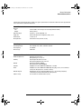
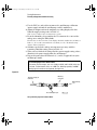
Setting up the Oscilloscope
After you have done a few basic tasks, you will connect probes to the
oscilloscope. The number of probes, and the type of probes that you will
use depends on the oscilloscope model that you have.
• When using the Agilent 54621A and 54622A 2-channel Oscilloscopes, and
the Agilent 54624A 4-channel Oscilloscope, you will connect and use analog
probes to examine analog signals.
Analog channels
(2 or 4, depending
on the oscilloscope
model)
• When using the Agilent 54621D and 54622D Mixed-Signal Oscilloscopes, you
will connect and use both analog and digital probes to examine analog and
digital signals.
Analog channels (2)
Digital channels (16)
2-3
service.book Page 4 Wednesday, December 18, 2002 8:35 AM
Preparing the Oscilloscope for Use
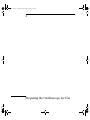
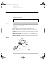
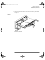
To adjust the handle
To adjust the handle
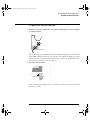
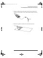
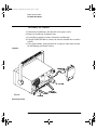
1 Grasp the handle pivot points on each side of the instrument and pull
the pivot out until it stops.
Agilent
54622D
MIXED SIGNAL OSCILLOSCOPE
CHANNEL
Time/Div
Select
1s
0
5 ns
15
INPUTS
2 Without releasing the pivots, swivel the handle to the desired position.
Then release the pivots. Continue pivoting the handle until it clicks into
a set position.
2-4
service.book Page 5 Wednesday, December 18, 2002 8:35 AM
Preparing the Oscilloscope for Use
To power-on the oscilloscope
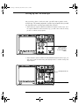
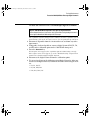
To power-on the oscilloscope
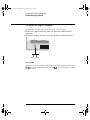
1 Connect the power cord to the rear of the oscilloscope, then to a suitable
ac voltage source.
The oscilloscope power supply automatically adjusts for input line voltages in the
range 100 to 240 VAC. Therefore, you do not need to adjust the input line voltage
setting. The line cord provided is matched to the country of origin. Ensure that
you have the correct line cord. See table 1-3
2 Press the power switch.
Trigger out
~5V
Some front panel key lights will come on and the oscilloscope will be operational
in about 5 seconds.
2-5
service.book Page 6 Wednesday, December 18, 2002 8:35 AM
Preparing the Oscilloscope for Use
To adjust the display intensity
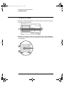
To adjust the display intensity
The Intensity control is at the lower left corner of the front panel.
• To decrease display intensity, rotate the Intensity control counterclockwise.
• To increase display intensity, rotate the Intensity control clockwise.
Dim
Bright
Intensity control
The grid or graticule intensity on the display can be adjusted by pressing the
Display key, then turn the Entry knob (labeled
on the front panel) to adjust
the Grid control.
2-6
service.book Page 7 Wednesday, December 18, 2002 8:35 AM
Preparing the Oscilloscope for Use
To connect the oscilloscope probes
To connect the oscilloscope probes
1 Connect the Agilent 10074C 1.5-meter, 10:1 oscilloscope probe to the
analog channel 1 or 2 BNC connector input on the oscilloscope, or
channel 1 through channel 4 on the 54624A.
Maximum input voltage for analog inputs:
CAT I 300 Vrms, 400 Vpk
CAT II 100 Vrms, 400 Vpk
with 10074C 10:1 probe: CAT I 500 Vpk, CAT II 400 Vpk
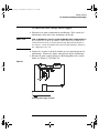
2 Connect the retractable hook tip on the probe tip to the circuit point of
interest. Be sure to connect the probe ground lead to a ground point on
the circuit.
The probe ground lead is connected to the oscilloscope chassis and the ground
wire in the power cord. If you need to connect the ground lead to a point in the
circuit that cannot be grounded to power ground, consider using a differential
probe.
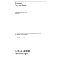
To compensate your probe
You should compensate you probes to match their characteristics to the
oscilloscope. A poorly compenstated probe can introduce measurement errors.
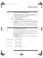
To compensate a probe, follow these steps:
1 Connect the probe from channel 1 to the Probe Comp signal on the lower-
right corner of the front panel.
2 Press Autoscale.
3 Use a nonmetallic tool to adjust the trimmer capacitor on the probe for
the flattest pulse possible.
Perfectly compensated
Over compensated
Under compensated
comp.cdr
2-7
service.book Page 8 Wednesday, December 18, 2002 8:35 AM
Preparing the Oscilloscope for Use
To use the digital probes (mixed-signal oscilloscope only)
To use the digital probes (mixed-signal oscilloscope
only)
1 If you feel it’s necessary, turn off the power supply to the circuit under
test.
Off
Turning off power to the circuit under test would only prevent damage that
might occur if you accidentally short two lines together while connecting
probes. You can leave the oscilloscope powered on because no voltage appears
at the probes.
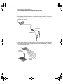
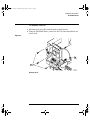
2 Connect the digital probe cable to D15 - D0 connector on the front panel
of the mixed-signal oscilloscope. The digital probe cable is indexed so
you can connect it only one way. You do not need to power-off the
oscilloscope.
Use only the Agilent part number 54620-68701 digital probe kit supplied with
the mixed-signal oscilloscope.
2-8
service.book Page 9 Wednesday, December 18, 2002 8:35 AM
Preparing the Oscilloscope for Use
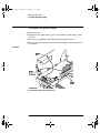
To use the digital probes (mixed-signal oscilloscope only)
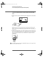
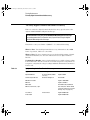
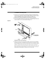
3 Connect a grabber to one of the probe leads. Be sure to connect the
ground lead. (Other probe leads are omitted from the figure for clarity.)
Grabber
4 Connect the grabber to a node in the circuit you want to test.
2-9
service.book Page 10 Wednesday, December 18, 2002 8:35 AM
Preparing the Oscilloscope for Use
To use the digital probes (mixed-signal oscilloscope only)
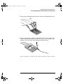
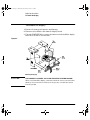
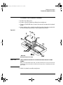
5 For high-speed signals, connect a ground lead to the probe lead, connect
a grabber to the ground lead, and attach the grabber to ground in the
circuit under test.
Signal Lead
Ground Lead
Grabber
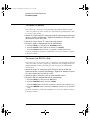
6 Connect the ground lead on each set of channels, using a probe grabber.
The ground lead improves signal fidelity to the instrument, ensuring
accurate measurements.
Channel
Pod Ground
Circuit
Ground
2-10
service.book Page 11 Wednesday, December 18, 2002 8:35 AM
Preparing the Oscilloscope for Use
To use the digital probes (mixed-signal oscilloscope only)
7 Repeat steps 3 through 6 until you have connected all points of interest.
Signals
Ground
8 If you need to remove a probe lead from the cable, insert a paper clip
or other small pointed object into the side of the cable assembly, and
push to release the latch while pulling out the probe lead.
Replacement parts are available. See the “Replaceable Parts” chapter for details.
2-11
service.book Page 12 Wednesday, December 18, 2002 8:35 AM
Preparing the Oscilloscope for Use
To connect a printer
To connect a printer
The oscilloscope connects to a parallel printer through the Parallel output
connector on the rear of the oscilloscope. You will need a parallel printer cable
to connect to the printer.
1 Attach the 25-pin small “D” connector to the Parallel output connector
on the rear of the oscilloscope. Tighten the thumbscrews on the cable
connector to secure the cable.
2 Attach the larger 36-pin “D” connector to the printer.
3 Set up the printer configuration on the oscilloscope.
a Press the Utility key, then press the Print Confg softkey.
b Press the Print to: softkey and set the interface to Parallel.
c Press the Format softkey and select your printer format from the list.
For more information on printer configuration, refer to the “Utilities” chapter
in the User’s Guide.
To connect an RS-232 cable
The oscilloscope can be connected to a controller or a PC through the RS-232
connector on the rear of the oscilloscope. An RS-232 cable is shipped with each
54622A/22D/24A oscilloscope and may be purchased for the 54621A/21D
oscilloscopes.
1 Attach the 9-pin “D” connector on the RS-232 cable to the RS-232
connector on the rear of the oscilloscope. Tighten the thumbscrews on
the cable connector to secure the cable
2 Attach the other end of the cable to your controller or pc.
3 Set up the RS-232 configuration on the oscilloscope.
Press the Utility key, then press the I/O softkey.
Press the Controller softkey and select RS-232.
Press the Baud softkey and set the baud rate to match your controller or pc.
Press the XON DTR softkey and set the handshake to match your controller
or pc.
For more information on RS-232 configuration, refer to the “Utilities” chapter
in the User’s Guide.
a
b
c
d
2-12
service.book Page 13 Wednesday, December 18, 2002 8:35 AM
Preparing the Oscilloscope for Use
To verify basic oscilloscope operation
To verify basic oscilloscope operation
1 Connect an oscilloscope probe to channel 1.
2 Attach the probe to the Probe Comp output on the lower-right side of
the front panel of the oscilloscope.
Use a probe retractable hook tip so you do not need to hold the probe.
3 Press the Save/Recall key on the front panel, then press the Default Setup
softkey under the display.
The oscilloscope is now configured to its default settings.
4 Press the Autoscale key on the front panel.
You should then see a square wave with peak-to-peak amplitude of about 5
divisions and a period of about 4 divisions as shown below. If you do not see
the waveform, ensure your power source is adequate, the oscilloscope is
properly powered-on, and the probe is connected securely to the front-panel
channel input BNC and to the Probe Comp calibration output.
Verifying Basic Oscilloscope Operation
2-13
service.book Page 14 Wednesday, December 18, 2002 8:35 AM
Getting started using the oscilloscope interface
When the oscilloscope is first turned on, it performs a self-test, then
momentarily shows a startup screen as shown below.
This menu is only accessible when the oscilloscope first starts up.
2-14
service.book Page 15 Wednesday, December 18, 2002 8:35 AM
Preparing the Oscilloscope for Use
To verify basic oscilloscope operation
• Press the Getting Started softkey to view the symbols used in the
oscilloscope softkey menus.
Use the Entry knob labeled
to adjust the parameter.
Press the softkey to display a pop up with a list of choices. Repeatedly
press the softkey until your choice is selected.
✓
Use the Entry knob labeled
or press the softkey to adjust the
parameter.
Option is selected and operational.
Feature is on. Press the softkey again to turn the feature off.
Feature is off. Press the softkey again to turn the feature on.
Press the softkey to view the menu.
Press the softkey to return to the previous menu.
Links you to another menu.
2-15
service.book Page 16 Wednesday, December 18, 2002 8:35 AM
Using Quick Help
The oscilloscope has a Quick Help system that provides user help for
each front-panel key and softkey on the oscilloscope. To view Quick Help
information:
1 Press and hold down the key for which you would like to view help.
2 Release the key after reading the message. Releasing the key returns
the oscilloscope to the previous state.
Selecting a language for Quick Help when the
oscilloscope starts up
When the oscilloscope first powers up, you can press the Language softkey to
select a language for viewing Quick Help. Successive press the Language softkey
until the desired language in the list selected.
You can also select and load a language later from the Utility Language menu.
2-16
service.book Page 17 Wednesday, December 18, 2002 8:35 AM
Preparing the Oscilloscope for Use
Selecting a language for Quick Help after you have been operating the oscilloscope
Selecting a language for Quick Help after you have been
operating the oscilloscope
1 Press the Utility key, then press the Language softkey to display the
Language menu.
2 Press the Language softkey until the desired language in the list selected.
If the language you want to load is grayed-out in the list, you will need to load
the language from floppy disk. The language file can be downloaded from
www.agilent.com/find/5462xsw or call an Agilent center and request a language
disk for your instrument
2-17
service.book Page 18 Wednesday, December 18, 2002 8:35 AM
Preparing the Oscilloscope for Use
Loading a language from floppy disk
Loading a language from floppy disk
Language files can be downloaded from www.agilent.com/find/5462xsw or call
an Agilent center and request a language disk for your instrument.
1 Insert the floppy disk with a language file into the floppy disk drive on
the oscilloscope.
2 Press the Utility key, then press the Language softkey to display the
Language menu.
3 Press the Load Languages softkey to load the updated language file into
the oscilloscope.
4 Press the Language softkey and select the language to be viewed.
For more information about loading and deleting languages, refer to the
“Utilities” chapter in the User’s Guide.
2-18
service.book Page 19 Wednesday, December 18, 2002 8:35 AM
Cleaning the oscilloscope
1 Disconnect power from the instrument.
CAUTION
Avoid Damage to Sensitive Electronic Components!
Do not use too much liquid in cleaning the oscilloscope. Water can enter the
front-panel keyboard, control knobs, or floppy disk damaging sensitive
electronic components.
2 Clean the oscilloscope with a soft cloth dampened with a mild soap and
water solution.
3 Make sure that the instrument is completely dry before reconnecting to
a power source.
2-19
service.book Page 20 Wednesday, December 18, 2002 8:35 AM
2-20
service.book Page 1 Wednesday, December 18, 2002 8:35 AM
3
Testing Performance
service.book Page 2 Wednesday, December 18, 2002 8:35 AM
Testing Performance
This chapter explains how to verify correct oscilloscope operation and
perform tests to ensure that the oscilloscope meets the performance
specifications.
To completely test and troubleshoot the mixed-signal oscilloscope, you
will create and use a test connector accessory, as described in this
chapter.
• The test connector makes it easy for you to connect the oscilloscope
probes to function generators and measurement equipment with
minimum electrical distortion.
• The connector is used in the digital channel threshold accuracy test.
Let the Equipment Warm Up Before Testing For accurate test results, let
the test equipment and the oscilloscope warm up 30 minutes before testing.
Verifying Test Results During the tests, record the readings in the
Performance Test Record at the end of this chapter for your oscilloscope. To
verify whether a test passes, verify that the reading is within the limits in the
Performance Test Record.
If a performance test fails
If a performance test fails, first perform the User Cal procedure given in Chapter 4.
If the User Cal procedure does not correct the problem, refer to Chapter 4, Calibrating
and Adjusting.
3-2
service.book Page 3 Wednesday, December 18, 2002 8:35 AM
Testing Performance
List of Test Equipment
List of Test Equipment
Below is a list of test and equipment and accessories required to perform
the performance test verification procedures.
Equipment
Critical Specifications
Recommended Model/
Part Number
Test connector, 8-by-2
Not required if 01660-63801 Test Fixture is available
See “To construct the test connector”
later in this chapter
n/a
Test fixture
For testing digital channel threshold accuracy
Agilent 01660-63801
Digital Multimeter
0.1 mV resolution, 0.005% accuracy
Agilent 34401A
Power Splitter
Outputs differ by 0.15 dB
Agilent 11667B
Power Supply
DC offset voltage of -5.5 V to 35.5 V, 0.1 mV resolution
Agilent 3245A
Oscilloscope Calibrator
25 MHz—100 MHz sine wave, 5 ppm
Fluke 5820A
BNC banana cable
Agilent 11001-60001
BNC cable (qty 3)
Agilent 10503A
Probe cable
Agilent 01650-61607
Shorting Cap BNC
Agilent 1250-0774
Adapter
BNC(f) to banana(m)
Agilent 1251-2277
Feedthrough
50Ω, BNC (m) and (f)
Agilent 11048C
Adapter
BNC Tee (m) (f) (f)
Agilent 1250-0781
Blocking capacitor
Adapter (qty 3)
Agilent 10240-60001
N(m) to BNC(f)
Agilent 1250-0780
3-3
service.book Page 4 Wednesday, December 18, 2002 8:35 AM
Testing Performance
To construct the test connector
To construct the test connector
The Agilent 54621D/22D Mixed-Signal Oscilloscope has digital channels that
you will need to connect to test equipment during testing. To easily connect the
digital channels, you will construct a test connector only if the 01660-63801
Test Fixture is not available.
Construct Test Connector only if Test Fixture is not available
The test connector is not required if 01660-63801 Test Fixture is available.
Table 3-1
Materials Required to Construct the Test Connectors
Description
BNC (f) Connector
Berg Strip, 8-by-2
Jumper wire
Recommended Part
Agilent 1250-1032
Qty
1
1
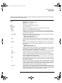
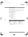
1 Obtain a BNC connector and an 8-by-2 section of Berg strip.
2 On one side of the Berg strip, solder a jumper wire to all of the pins.
3 On the other side of the Berg strip, solder another jumper wire to all of
the pins.
4 Solder the center of the BNC connector to a center pin on one of the
rows on the Berg strip.
5 Solder the ground tab of the BNC connector to a center pin on the other
row on the Berg strip.
Figure 3-1
Constructing the 8-by-2 Connector
3-4
service.book Page 5 Wednesday, December 18, 2002 8:35 AM
Testing Performance
To test the 54621D/22D Oscilloscope digital channels
To test the 54621D/22D Oscilloscope digital channels
Only the 54621D/22D Mixed-Signal Oscilloscope has Digital Channels
You need to perform these instructions only if you will be testing the digital channels
on the Agilent 54621D/22D Mixed-Signal Oscilloscope.
The acquisition system testing provides confidence that the acquisition system
is functioning correctly. It does not, however, check a particular specification.
1 Disconnect all probes from the circuit under test and from any other
input source.
2 Using probe leads and grabbers, connect digital channels D0, D1, D2,
and D3 to the calibration point on the 54621D/22D front panel.
3 Press the Autoscale key.
If four square waves appear, the acquisition system is functioning correctly.
If the square waves do not appear, go to the “Troubleshooting” chapter. Then
return here to finish testing the digital channels.
4 Disconnect the digital channels from the calibration point.
5 Use steps 2 and 3 to test the following sets of digital channels. After you
test one set of digital channels, remove them before connecting the next
set.
• D4, D5, D6, D7
• D8, D9, D10, D11
• D12, D13, D14, D15
3-5
service.book Page 6 Wednesday, December 18, 2002 8:35 AM
Testing Performance
To verify digital channel threshold accuracy
To verify digital channel threshold accuracy
This test verifies the digital channel threshold accuracy specification of the
Agilent 54621D/22D Mixed-Signal Oscilloscope.
Test Threshold Accuracy only on the 54621D/22D Mixed-Signal Oscilloscope
You need to perform these instructions only if you will be testing the Agilent
54621D/22D Mixed-Signal Oscilloscope.
Threshold accuracy test limits= ±(100 mV + 3% of threshold setting)
When to Test You should perform this test every 24 months or after 4000
hours of operation, whichever comes first.
What to Test Use these instructions to test the threshold settings of digital
channels D7-D0. Then, use the same instructions to test digital channels
D15-D8.
Verifying Test Results After each threshold test, record the voltage reading
in the Performance Test Record at the end of this chapter. To verify whether a
test passes, verify that the voltage reading is within the limits in the Performance
Test Record.
Table 3-2
Equipment Required to Test Threshold Accuracy
Equipment
Critical Specifications
Recommended Model/Part
Digital Multimeter
0.1 mV resolution, 0.005%
accuracy
Agilent 34401A
Oscilloscope Calibrator
DC offset voltage 6.3 V
Fluke 5820A
BNC-Banana Cable
Agilent 11001-60001
BNC Tee
Agilent 1250-0781
BNC Cable
Fluke 50Ω cable, P/N 686318
BNC Test Connector, 8-by-2
User-built (See “Obtain a BNC
connector and an 8-by-2 section
of Berg strip.” on page 3-4.)
Test Fixture
Probe Cable
3-6
PV test fixture
Agilent 01660-63801
Agilent 01650-61607
service.book Page 7 Wednesday, December 18, 2002 8:35 AM
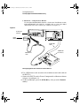
Testing Performance
To verify digital channel threshold accuracy
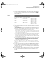
1 Turn on the test equipment and the oscilloscope. Let them warm up for
30 minutes before starting the test.
2 Set up the oscilloscope calibrator.
a Set the oscilloscope calibrator to provide a DC offset voltage at the
Channel 1 output.
b Use the multimeter to monitor the oscilloscope calibrator DC output
voltage.
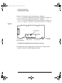
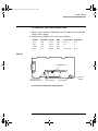
3 Use either method 1 or method 2, described in the following, to connect
the digital channels for testing.
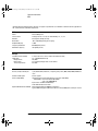
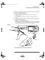
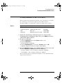
a Method 1 — Using the Test Connector
Use the 8-by-2 test connector and the BNC cable assembly to connect digital
channels D0-D7 to one side of the BNC Tee. Then connect the D0-D7 ground
lead to the ground side of the 8-by-2 connector. See figure 3-2.
Figure 3-2
5 46 2 0 A
1 6 C H AN N EL 5 0 0 M S a/ s
Oscilloscope
Calibrator
STO R A G E
M ix e d S ig n a l O sc illo sc o p e
M e a sure tim e
S a ve/ Re c a ll
E ntry
H O RIZO N TA L
TRIG G E R
D ela y
C HANNEL
Tim e/D iv
Sele c t
IN P U TS
Digital
Multimeter
Po sitio n
Trigg e r o u t
HP 34401A
Line
!
Ex t trigg e r in
!
!
Channels 8 - 15
BNC-Banana
cable
Channels 0 - 7
Test
Connector
thresh.cdr
Setting Up Equipment and Test Connector for the Threshold Test
3-7
service.book Page 8 Wednesday, December 18, 2002 8:35 AM
Testing Performance
To verify digital channel threshold accuracy
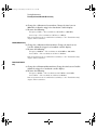
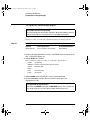
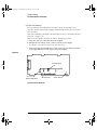
b Method 2 — Using the Test Fixture
Use the Agilent 01660-63801 Performance Verification Test Fixture and the
Agilent 01650-61607 cable, BNC Tee, and BNC cable to connect the digital
channels D0 - D15 to the oscilloscope calibrator. See figure 3-3.
Figure 3-3
$
1 6 C HA N N EL 5 0 0 MS a/s
STO RA G E
M ix e d S i g n a l O s c i l lo s c o p e
Me a su re tim e
Oscilloscope
Calibrator
E n try
Sa ve/R ec al l
H O RIZO N TA L
TRIG G ER
D ela y
C H AN N EL
Time /D iv
Selec t
INP UTS
Po sition
Digital
Multimeter
Trig g e r o ut
HP 34401A
Lin e
!
Ex t trig g e r in
!
!
01650-61607
Cable
BNC-Banana
cable
01660-63801
Test Fixture
thresh2.cdr
Setting Up Equipment and Test Fixture for the Threshold Test
4 Use a BNC-banana cable to connect the multimeter to the other side of
the BNC Tee.
5 Connect the BNC Tee to the Channel 1 output of the calibrator as shown
in figure 3-2 and figure 3-3.
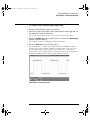
6 On the oscilloscope, press the D7 Thru D0 key, then press the Threshold
softkey.
3-8
service.book Page 9 Wednesday, December 18, 2002 8:35 AM
Testing Performance
To verify digital channel threshold accuracy
7 Press the oscilloscope User softkey, then turn the Entry knob (
) on
the front panel on the oscilloscope to set the threshold test settings as
shown in Table 3-3.
Table 3-3
Threshold Accuracy Voltage Test Settings
Threshold voltage setting
DC offset voltage setting
(in oscilloscpe User softkey) (on oscilloscope calibrator)
Limits
+5.00 V
+5.250 V ±1 mV dc
Lower limit = +4.750 V
Upper limit = +5.250 V
–5.00 V
–4.750 V ±1 mV dc
Lower limit = –5.250 V
Upper limit = –4.750 V
0.00 V
+100m V ±1 mV dc
Upper limt = +100 mV
Lower limit = –100 mV
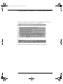
8 Do the following steps for each of the threshold voltage levels shown
in Table 3-3.
a Set the threshold voltage shown in the User softkey using the Entry knob on
the oscilloscope.
b Enter the corresponding DC offset voltage on the oscilloscope calibrator
front panel. Then use the multimeter to verify the voltage.
Digital channel activity indicators are displayed on the status line at the top
of the oscilloscope display. The activity indicators for D7-D0 should show all
of the channels at digital high levels.
c Use the knob on the oscilloscope calibrator to decrease the offset voltage,
in increments of 10 mV, until the activity indicators for digital channels
D7-D0 are all at digital low levels. Record the oscilloscope calibrator voltage
in the performance test record.
d Use the knob on the oscilloscope calibrator to increase the offset voltage,
in increments of 10 mV, until the activity indicators for digital channels
D7-D0 are all at digital high levels. Record the oscilloscope calibrator
voltage in the performance test record.
Before proceeding to the next step, make sure that you have recorded the
oscilloscope calibrator voltage levels for each of the threshold settings shown
in Table 3-3.
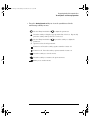
9 Use the 8-by-2 test connector or the Agilent 01660-63801 Test Fixture
to connect digital channels D15-D8 to the output of the oscilloscope
calibrator. Then connect the D15-D8 ground lead to the ground side of
the 8-by-2 connector.
10 Repeat this procedure for digital channels D15-D8 to verify threshold
accuracy and record the threshold levels in the Performance Test
Record.
3-9
service.book Page 10 Wednesday, December 18, 2002 8:35 AM
Testing Performance
To verify voltage measurement accuracy
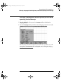
To verify voltage measurement accuracy
This test verifies the voltage measurement accuracy. In this test, you will
measure the output of a power supply using dual cursors on the oscilloscope,
and compare the results with the multimeter reading.
Test limits: ±2.0% of full scale ±1 LSB*
• Full scale is defined as 16 mV on the 1 mV/div range.
• Full scale on all other ranges is defined as 8 divisions times the
V/div setting.
*1 LSB = 0.4% of full scale
Table 3-4
Equipment Required to Verify Voltage Measurement Accuracy
Equipment
Critical Specifications
Recommended Model/Part
Power supply
14 mV to 35 Vdc,
0.1 mV resolution
Fluke 5820A or Agilent 3245A
Digital multimeter
Better than 0.01% accuracy
Agilent 34401A
Cable
BNC, Qty 2
Agilent 10503A
Shorting cap
BNC
Agilent 1250-0774
Adapter
BNC (f) to banana (m)
Agilent 1251-2277
Adapter
BNC tee (m) (f) (f)
Agilent 1250-0781
Blocking capacitor
Agilent 10240B
Do this procedure first for Channel 1. Then repeat the procedure for Channel 2.
1 Set up the oscilloscope.
a Adjust the channel 1 position knob to place the baseline at approximately
0.5 division from the bottom of the display.
3-10
service.book Page 11 Wednesday, December 18, 2002 8:35 AM
Testing Performance
To verify voltage measurement accuracy
b Set the Volts/Div setting to the value in the first line in Table 3-5.
Table 3-5
Settings Used to Verify Voltage Measurement Accuracy
Volts/Div Setting Power Supply Setting Test Limits
5 V/Div
35 V
34.04 V
to 35.96 V
2 V/Div
14 V
13.616 V
to 14.384 V
1 V/Div
7V
6.808 V
to 7.192 V
0.5 V/Div
3.5 V
3.404 V
to 3.596 V
0.2 V/Div
1.4 V
1.3616 V
to 1.4384 V
0.1 V/Div
700 mV
680.8 mV
to 719.2 mV
50 mV/Div
350 mV
340.4 mV
to 359.6 mV
20 mV/Div
140 mV
136.16 mV to 143.84 mV
10 mV/Div
70 mV
68.08 mV
to 71.92 mV
5 mV/Div
35 mV
34.04 mV
to 35.96 mV
2 mV/Div
14 mV
13.616 mV to 14.384 mV
1 mV/Div*
7 mV
6.616 mV
to 7.384 mV
*Full scale is defined as 16 mV on the 1 mV/div range.
Full scale on all other ranges is defined as 8 divisions times the V/div setting.
c Press the Acquire key. Then press the Averaging softkey and set #Avgs to 64.
Wait a few seconds for the measurement to settle.
2 Press the Cursors key, set the Mode softkey to Normal, then press the X Y
softkey and select Y. Press the Y1 softkey, then use the Entry knob
(labeled
the signal.
on the front panel) to set the Y1 cursor on the baseline of
3-11
service.book Page 12 Wednesday, December 18, 2002 8:35 AM
Testing Performance
To verify voltage measurement accuracy
3 Use the BNC tee and cables to connect the oscilloscope calibrator
/power supply to both the oscilloscope and the multimeter.
4 Adjust the output so that the multimeter reading displays the first
Volts/div supply setting value in Table 3-5.
Wait a few seconds for the measurement to settle.
5 Press the Y2 softkey, then position the Y2 cursor to the center of the
voltage trace using the Entry knob.
The ∆Y value on the lower line of the display should be within the test limits of
Table 3-5. If a result is not within the test limits, see the “Troubleshooting”
chapter. Then return here.
6 Continue to check the voltage measurement accuracy with the
remaining Volts/div setting values in Table 3-5.
7 When you are finished checking all of the power supply setting values,
disconnect the power supply from the oscilloscope.
8 Repeat this procedure for Channels 2, 3, and 4, if applicable on your
oscilloscope model.
Use a Blocking Capacitor to Reduce Noise
On the more sensitive ranges, such as 1 mV/div, 2 mV/div, and 5 mV/div, noise may
be a factor. To eliminate the noise, use a BNC Tee, blocking capacitor, and BNC
shorting cap to shunt the noise to ground. See figure 3-4.
Figure 3-4
Blocking
Capacitor
To Power Supply or
Calibrator
BNC shorting
cap
To oscilloscope input
Using a Blocking Capacitor to Reduce Noise
3-12
service.book Page 13 Wednesday, December 18, 2002 8:35 AM
Testing Performance
To verify bandwidth
To verify bandwidth
This test verifies bandwidth. In this test you will use an oscilloscope calibrator
with a level sinewave output.
You will use the peak-to-peak voltage both at 1 MHz and at bandwidth frequency
to verify the bandwidth response of the oscilloscope.
54622A, 54622D, and 54624A
Test limits at 1 mV/div to 5 V/div:
• All channels (±3 dB)
• dc to 100 MHz
• ac coupled 10 Hz to 100 MHz
54621A and 54621D
Test limits at 1 mV/div to 5 V/div:
• All channels (±3 dB)
• dc to 60 MHz
• ac coupled 10 Hz to 60 MHz
Table 3-6
Equipment Required to Verify Bandwidth
Equipment
Critical Specifications
Oscilloscope Calibrator
Recommended Model/Part
Fluke 5820A
Cable *
Type N (m), 24-inch
Agilent 11500B
Feedthrough
50Ω, BNC (m) and (f)
Agilent 11048C
* The oscilloscope calibrator is supplied with 2 or more coaxial cables N (m), BNC (m),
1 meter long, Fluke P/N 686318.
3-13
service.book Page 14 Wednesday, December 18, 2002 8:35 AM
Testing Performance
To verify bandwidth
1 Connect the oscilloscope calibrator output through a 50Ω feedthrough
to the oscilloscope channel 1 input.
2 Set up the oscilloscope.
a Set the time base to 500 ns/div.
b Set the Volts/Div for channel 1 to 200 mV/div.
c Press the Acquire key, then press the Averaging softkey.
d Turn the Entry knob to set # Avgs to 8 averages.
3
4
5
6
Set the calibrator to “Level Sine” and OPR/STBY to “OPR”.
Set the calibrator for 1 MHz and six divisions of amplitude.
Press Autoscale on the oscilloscope.
Press the Quick Meas key, then press the Peak-Peak softkey.
Wait a few seconds for the measurement to settle (averaging is then complete).
View the Pk-Pk reading at the bottom of the display.
Record the reading: Vp-p = _______ V.
7 Change the frequency of the signal generator to the value shown below
for your instrument.
Table 3-7
Signal Generator Frequency Setting
Selected Channel
54621A/21D
54622A/22D
54624A
Channel 1
60 MHz
100 MHz
100 MHz
Channel 2
60 MHz
100 MHz
100 MHz
Channel 3
—
—
100 MHz
Channel 4
—
—
100 MHz
8 Change the time base to 5 ns/div.
a Wait a few seconds for the measurement to settle.
b View the Pk-Pk reading at the bottom of the display.
c Record the reading: Vp-p = ______ mV.
9 Calculate the response using this formula:
Step8Result
20 log 10 ⋅ -------------------------------Step6Result
If the result is not ±3 dB, see the “Troubleshooting” chapter. Then return here.
10 Repeat this procedure (steps 1 to 9) for channel 2, 3, and 4, as applicable
to your oscilloscope model.
Proceed to the next step after you have completed the procedure for channels
2, 3, and 4, as applicable.
3-14
service.book Page 15 Wednesday, December 18, 2002 8:35 AM
Testing Performance
To verify horizontal Dt and 1/Dt accuracy
To verify horizontal ∆t and 1/∆t accuracy
This test verifies the horizontal ∆t and 1/∆t accuracy. In this test, you will use
the oscilloscope to measure the output of a time mark generator.
Test limits: ±0.01% of reading ±0.1% of full scale ±40 ps (same channel)
Table 3-8
Equipment Required to Verify Horizontal ∆t and 1/∆t Accuracy
Equipment
Critical Specifications
Recommended Model/Part
Oscilloscope Calibrator
Stability 5 ppm after 1/2 hour
Fluke 5820A
Cable
BNC, 3 feet
Agilent 10503A
Feedthrough
50Ω, BNC connectors (m) and (f)
Agilent 11048C
1 Connect the oscilloscope calibrator to channel 1 using the 50 Ω
feedthrough at the oscilloscope input. Then, select Marker and set the
calibrator for 100 µs markers.
2 Set up the oscilloscope.
a Press the Display key, then set the Vectors softkey to off.
b Press the Autoscale key.
c Set the time base to 20 µs/div.
d Press the Main/Delayed key, then set the Time Ref softkey to Left.
e Adjust the Trigger Level knob to obtain a stable display.
3 Press the Quick Meas softkey, set the Source softkey to 1, then select and
measure Frequency and Period. Measure the following:
Frequency 10 kHz — The test limits are 9.98 kHz to 10.02 kHz.
Period 100 µs — The test limits are 99.79 µs to 100.2 µs.
If the measurements are not within the test limits, see the “Troubleshooting”
chapter. Then return here.
3-15
service.book Page 16 Wednesday, December 18, 2002 8:35 AM
Testing Performance
To verify horizontal Dt and 1/Dt accuracy
4 Change the calibrator to 1-µs markers. Change the time base to
200 ns/div. Adjust the trigger level to obtain a stable display.
5 Measure the following:
Frequency 1 MHz — The test limits are 997.9 kHz to 1.002 MHz.
Period 1 µs — The test limits are 997.9 ns to 1.002 µs.
If the measurements are not within the test limits, see the “Troubleshooting”
chapter. Then return here.
54622A/22D/24A only
6 Change the calibrator to 10-ns markers. Change the time base to
5 ns/div. Adjust the trigger level to obtain a stable display.
7 Measure the following:
Frequency 100 MHz — The test limits are 99.10 MHz to 100.9 MHz.
Period 10 ns — The test limits are 9.91 ns to 10.09 ns.
If the measurements are not within the test limits, see the “Troubleshooting”
chapter. Then return here.
54621A and 54621D
only
8 Change the calibrator to 20 ns markers. Change the time base to 5 ns/div.
Adjust the trigger level to obtain a stable display.
9 Measure the following:
Frequency 50 MHz — The test limits are 49.77 MHz to 50.23 MHz.
Period 20 ns — The test limits are 19.91 ns to 20.09 ns.
If the measurements are not within the test limits, see the “Troubleshooting”
chapter. Then return here.
3-16
service.book Page 17 Wednesday, December 18, 2002 8:35 AM
Testing Performance
To verify trigger sensitivity
To verify trigger sensitivity
This test verifies the trigger sensitivity. In this test, you will apply 25 MHz to the
oscilloscope. You will then decrease the amplitude of the signal to the specified
levels, and check to see if the oscilloscope is still triggered. You will then repeat
the process at the upper bandwidth limit.
Test limits for the Internal trigger:
1 mV to 5 V/div (dc to max bandwidth): greater of 0.35 div or 2.5 mVp-p
Test limits for the External trigger:
dc to 25 MHz: <75 mVp-p
25 MHz to max bandwidth: <150 mVp-p
Table 3-9
Equipment Required to Verify Trigger Sensitivity
Equipment
Critical Specifications
Recommended Model/Part
Oscilloscope Calibrator
25-MHz, 60-MHz and 100-MHz sine
waves
Fluke 5820A
Power splitter
Outputs differ < 0.15 dB
Agilent 11667B
Cable *
BNC, Qty 3
Agilent 10503A
Adapter
N (m) to BNC (f), Qty 3
Agilent 1250-0780
Feedthrough
50Ω, BNC connectors (m) and (f)
Agilent 11048C (2 required)
* The oscilloscope calibrator is supplied with 2 or more coaxial cables N (m), BNC (m),
1 meter long, Fluke P/N 686318.
3-17
service.book Page 18 Wednesday, December 18, 2002 8:35 AM
Testing Performance
To verify trigger sensitivity
Test Internal Trigger Sensitivity
1 Press the Save/Recall key, then press the Default Setup softkey.
2 Connect the calibrator to channel 1 using a 50Ω feedthrough at the
oscilloscope input.
3 Verify the trigger sensitivity at 25 MHz and 0.35 divisions.
a Set the output of the calibrator to 25 MHz, and set the amplitude to about
b
c
d
e
f
100 mVp-p.
Press the Autoscale key.
Set the time base to 50 ns/div.
Set channel 1 to 100 mV/div.
Decrease the output of the calibrator until 0.35 vertical divisions of the
signal are displayed.
The trigger should be stable. If the trigger is not stable, try adjusting the
trigger level. If adjusting the trigger level makes the trigger stable, the test
still passes. If adjusting the trigger does not help, see the “Troubleshooting”
chapter. Then return here.
Record the result as Pass or Fail in the Performance Test Record.
4 Verify the trigger sensitivity at maximum bandwidth and 0.35 division.
a Change the output of the calibrator to 100 MHz for the 54622A/22D/24A or
60 MHz or the 54621A/21D, and set the amplitude to about 100 mVp-p.
b Set the time base to 10 ns/div.
c Decrease the output of the calibrator until 0.35 vertical divisions of the
signal is displayed.
The trigger should be stable. If the trigger is not stable, try adjusting the
trigger level. If adjusting the trigger level makes the trigger stable, the test
still passes. If adjusting the trigger does not help, see the “Troubleshooting”
chapter. Then return here.
d Record the result as Pass or Fail in the Performance Test Record.
5 Repeat this procedure for channels 2, 3, and 4, as applicable to your
oscilloscope model.
3-18
service.book Page 19 Wednesday, December 18, 2002 8:35 AM
Testing Performance
To verify trigger sensitivity
Test External Trigger Sensitivity
Verify the external trigger sensitivity at these settings:
100 MHz (54622A/22D/24A), <150 mVp-p
60 MHz (54621A/21D), <150 mVp-p
25 MHz (All models), <75 mVp-p
1 Use the power splitter to connect the calibrator to both the channel 1
input and the external trigger input. The Ext Trigger input is on the rear
panel of the mixed-signal oscilloscope and the 4-channel oscilloscope.
Connect 50Ω feedthroughs to the oscilloscope inputs.
2 Change the output of the calibrator to 100 MHz for the 54622A/22D/24A
or 60 MHz for the 54621A/21D, and set the amplitude to 106 mVrms
(300 mVp-p).
The power splitter divides the 300 mVp-p so that 150 mVp-p is applied to each
of the oscilloscope inputs.
3 Press the Autoscale key.
4 Press the Trigger Edge key, then press the Ext softkey to set the trigger
source to external trigger.
5 Check for stable triggering, and adjust the trigger level if necessary.
6 Record the results as Pass or Fail in the Performance Test Record.
If the test fails, see the “Troubleshooting” chapter. Then return here.
7 Change the output of the calibrator to 25 MHz and set the amplitude to
25.74 mVrms (75 mVp-p).
8 Check for stable triggering, and adjust the trigger level if necessary.
9 Record the results as Pass or Fail in the Performance Test Record.
If the test fails, see the “Troubleshooting” chapter. Then return here.
3-19
service.book Page 20 Wednesday, December 18, 2002 8:35 AM
Agilent 54622A/22D/24A Performance Test Record
Agilent 54622A/54622D/54624A
Serial No. ______________________________________
Test Interval ____________________________________
Recommended Next Testing ________________________
Test by _____________________________
Work Order No. ______________________
Temperature ____________
Threshold
Accuracy Test
(100 mV + 3% of
threshold setting)
Limits
4.750 V
5.250 V
-5.250 V
-4.750 V
-100 mV
100 mV
Ch D7-D0
________
________
________
________
________
________
Ch D15-D8
________
________
________
________
________
________
Test Limits
34.04 V to 35.96 V
13.616 V to 14.384 V
6.808 V to 7.192 V
3.404 V to 3.596 V
1.3616 V to 1.4384 V
680.8 mV to 719.2 mV
340.4 mV to 359.6 mV
136.16 mV to 143.84 mV
68.08 mV to 71.92 mV
34.04 mV to 35.96 mV
13.616 mV to 14.384 mV
6.616 mV to 7.384 mV
Channel 1
________
________
________
________
________
________
________
________
________
________
________
________
Channel 2
________
________
________
________
________
________
________
________
________
________
________
________
Test Limits
3 dB at 100 MHz
Channel 1 Channel 2 Channel 3 Channel 4
________ ________ ________ ________
Test Limits
9.98 kHz to 10.02 kHz
99.79 µs to 100.2 µs
997.9 kHz to 1.002 MHz
997.9 ns to 1.002 µs
99.10 MHz to 100.9 MHz
9.91 ns to 10.09 ns
Results
________
________
________
________
________
________
Specification
5 V - 250 mV
5 V + 250 mV
-5 V - 250 mV
-5 V + 250 mV
0 V - 100 mV
0 V + 100 mV
Voltage Measurement Accuracy
Range
Power Supply Setting
5 V/Div
35 V
2 V/Div
14 V
1 V/Div
7V
500 mV/Div
3.5 V
200 mV/Div
1.4 V
100 mV/Div
700 mV
50 mV/Div
350 mV
20 mV/Div
140 mV
10 mV/Div
70 mV
5 mV/Div
35 mV
2 mV/Div
14 mV
1 mV/Div
7 mV
Bandwidth
Horizontal ∆t and 1/∆t Accuracy
Generator Setting
Frequency
10 kHz
Period
100 µs
Frequency
1 MHz
Period
1 µs
Frequency
100 MHz
Period
10 ns
Trigger Sensitivity
Internal trigger
External trigger
3-20
Channel 3
________
________
________
________
________
________
________
________
________
________
________
________
Channel 4
________
________
________
________
________
________
________
________
________
________
________
________
Test Limits
Channel 1 Channel 2 Channel 3 Channel 4
25 MHz at 0.35 division ________ ________ ________ ________
100 MHz at 0.35 division ________ ________ ________ _______
Ext
________
25 MHz at <75 mVp-p
100 MHz at <150 mVp-p ________
service.book Page 21 Wednesday, December 18, 2002 8:35 AM
Agilent 54621A/21D Performance Test Record
Agilent 54621A/54621D
Serial No. ______________________________________
Test Interval ____________________________________
Recommended Next Testing ________________________
Test by _____________________________
Work Order No. ______________________
Temperature ____________
Threshold
Accuracy Test
(100 mV + 3% of
threshold setting)
Limits
4.750 V
5.250 V
-5.250 V
-4.750 V
-100 mV
100 mV
Ch D7-D0
________
________
________
________
________
________
Ch D15-D8
________
________
________
________
________
________
Test Limits
34.04 V to 35.96 V
13.616 V to 14.384 V
6.808 V to 7.192 V
3.404 V to 3.596 V
1.3616 V to 1.4384 V
680.8 mV to 719.2 mV
340.4 mV to 359.6 mV
136.16 mV to 143.84 mV
68.08 mV to 71.92 mV
34.04 mV to 35.96 mV
13.616 mV to 14.384 mV
6.616 mV to 7.384 mV
Channel 1
________
________
________
________
________
________
________
________
________
________
________
________
Channel 2
________
________
________
________
________
________
________
________
________
________
________
________
Test Limits
3 dB at 60 MHz
Channel 1 Channel 2
________ ________
Test Limits
9.98 kHz to 10.02 kHz
99.79 µs to 100.2 µs
997.9 kHz to 1.002 MHz
997.9 ns to 1.002 µs
49.77 MHz to 50.23 MHz
19.91 ns to 20.09 ns
Results
________
________
________
________
________
________
Test Limits
25 MHz at 0.35 division
60 MHz at 0.35 division
Channel 1 Channel 2
________ ________
________ ________
Ext
________
________
Specification
5 V - 250 mV
5 V + 250 mV
-5 V - 250 mV
-5 V + 250 mV
0 V - 100 mV
0 V + 100 mV
Voltage Measurement Accuracy
Range
Power Supply Setting
5 V/Div
35 V
2 V/Div
14 V
1 V/Div
7V
500 mV/Div
3.5 V
200 mV/Div
1.4 V
100 mV/Div
700 mV
50 mV/Div
350 mV
20 mV/Div
140 mV
10 mV/Div
70 mV
5 mV/Div
35 mV
2 mV/Div
14 mV
1 mV/Div
7 mV
Bandwidth
Horizontal ∆t and 1/∆t Accuracy
Generator Setting
Frequency
10 kHz
Period
100 µs
Frequency
1 MHz
Period
1 µs
Frequency
50 MHz
Period
20 ns
Trigger Sensitivity
Internal trigger
External trigger
25 MHz at <75 mVp-p
60 MHZ at <150 mVp-p
Channel 3
________
________
________
________
________
________
________
________
________
________
________
________
Channel 4
________
________
________
________
________
________
________
________
________
________
________
________
3-21
service.book Page 22 Wednesday, December 18, 2002 8:35 AM
3-22
service.book Page 1 Wednesday, December 18, 2002 8:35 AM
4
Calibrating and Adjusting
service.book Page 2 Wednesday, December 18, 2002 8:35 AM
Calibrating and Adjusting
This chapter explains how to adjust the oscilloscope for optimum
operating performance. You should perform the hardware adjustments
and self-calibration according to the following recommendations.
• Perform hardware adjustments every 12 months or after 2,000 hours
of operation.
• Perform self-calibration:
• every 6 months or after 1000 hours of operation
• if the ambient temperature is >10 °C from the calibration temperature
• if you want to maximize the measurement accuracy
The amount of use, environmental conditions, and experience with other
instruments help determine if you need shorter adjustment intervals.
In this chapter, you will:
• Adjust the power supply
• Perform self-calibration
• Adjust the display
Let the Equipment Warm Up Before Adjusting
Before you start the adjustments, let the oscilloscope and test equipment
warm up for at least 30 minutes.
Read All Cautions and Warnings
Read the following cautions and warning before making adjustments or
performing self-calibration.
4-2
service.book Page 3 Wednesday, December 18, 2002 8:35 AM
Calibrating and Adjusting
WARNING
HAZARDOUS VOLTAGES !
Read the safety summary at the back of this book before proceeding.
Maintenance is performed with power supplied to the oscilloscope and with
the protective covers removed. Only trained service personnel who are aware
of the hazards involved should perform the maintenance. Whenever possible,
perform the procedures with the power cord removed from the oscilloscope.
CAUTION
REMOVE POWER TO AVOID DAMAGE !
Do not disconnect any cables or remove any assemblies with power applied
to the oscilloscope. Otherwise, damage to the oscilloscope can occur.
CAUTION
USE EXTERNAL FAN TO REDUCE TEMPERATURE !
When you must operate the oscilloscope with its cover removed, use an
external fan to provide continuous air flow over the samplers. Air flow over
the samplers is reduced when the cover is removed, which leads to higher than
normal operating temperatures. Have the fan blow air across the system PC
board where the heat sinks are located.
CAUTION
AVOID DAMAGE TO ELECTRONIC COMPONENTS !
Electrostatic discharge (ESD) can damage electronic components. When you
use any of the procedures in this chapter, use proper ESD precautions. As a
minimum, place the oscilloscope on a properly grounded ESD mat and wear a
properly grounded ESD strap.
4-3
service.book Page 4 Wednesday, December 18, 2002 8:35 AM
Calibrating and Adjusting
To adjust the power supply
To adjust the power supply
The oscilloscope power supply has both a +3.3 V adjustment, and a
+5.1 V / -5.2 V balance adjustment. Other oscilloscope voltages are based on
the +3.3 V adjustment.
In this procedure, you will use a digital multimeter to measure the +3.3 V and
+5.1 V / -5.2 V test points, and adjust the power supplies to be within tolerance,
if necessary.
Table 4-1
Equipment Required to Adjust the Power Supply
Equipment
Critical Specifications
Recommended Model/Part
Digital multimeter
0.1 mV resolution, accuracy ±0.05%
Agilent 34401A
1 Prepare the oscilloscope for the voltage adjustment.
a Turn off the oscilloscope and disconnect the power cable.
b Remove the oscilloscope cover. For a list of parts, see the “Replaceable
Parts” chapter, then return here.
c Place the oscilloscope on its side.
d Connect the negative lead of the digital multimeter to a ground point on the
oscilloscope chassis.
e Reconnect the power cable.
f Turn on the oscilloscope.
4-4
service.book Page 5 Wednesday, December 18, 2002 8:35 AM
Calibrating and Adjusting
To adjust the power supply
2 Locate the power supply voltages at E204, E205, E207, and E208 on the
system board.
The power supply voltages are not labeled on the system board. See
Figure 4-1 for the locations.
Figure 4-1
( (
-
(
-
-
-
(
9 9
9 9
Low Voltage Power Supply Voltages (on the bottom of the oscilloscope)
3 Make sure that the voltage measurements are within the tolerances
listed in Table 4-2.
Table 4-2
Power Supply Voltage Tolerances
Supply Voltage
Tolerance
+5.1 V
±250 mV (4.85 V to 5.35 V)
-5.2 V
±156 mV (-5.04 V to -5.36 V)
+15.75 V
+1.260 V, -787 mV (+14.963 V to +17.010 V)
+3.3 V
±100 mV (+3.20 V to +3.40 V)
+8.2 V
±82 mV (+8.12 V to +8.28 V)
measure at J4 on the power supply board
4-5
service.book Page 6 Wednesday, December 18, 2002 8:35 AM
Calibrating and Adjusting
To adjust the power supply
4 If the +5.1 V measurement is out of tolerance, adjust the
+5.1 V / -5.2 V balance adjustment on the power supply. See Figure 4-2.
5 If the -5.2 V measurement is out of tolerance, adjust the
+5.1 V / -5.2 V balance adjustment on the power supply. See Figure 4-2.
The +15.75 V supply is not adjustable, and is dependent upon the +5.1 V supply.
Figure 4-2
+3.3V Adjustment
+5.1 / -5.2 V
Balance Adjustment
E2 and E3
8.5 V DC
Fan Connector
Printer Power
Low Voltage Power Supply Adjustments (on the top of the oscilloscope)
6 If adjusting the power supply does not bring all the voltages within
tolerance, go to the “Troubleshooting” chapter.
4-6
service.book Page 7 Wednesday, December 18, 2002 8:35 AM
Calibrating and Adjusting
To perform User Cal
To perform User Cal
Perform self-calibration:
• every 6 months or after 1000 hours of operation.
• if the ambient temperature is >10 °C from the calibration temperature.
• if you want to maximize the measurement accuracy.
The amount of use, environmental conditions, and experience with other
instruments help determine if you need shorter adjustment intervals.
User Cal performs an internal self-alignment routine to optimize the signal path
in the oscilloscope. The routine uses internally generated signals to optimize
circuits that affect channel sensitivity, offset, and trigger parameters.
Disconnect all inputs and allow the oscilloscope to warm up before performing
this procedure.
User Cal should be performed at least once a year, any time the ambient
temperature of the oscilloscope has changed more than 10 °C since the last User
Cal, or after any repair.
Performing User Cal will not invalidate your Certificate of Calibration.
Successful completion of User Cal does not certify this oscilloscope with a
National Institute of Standards and Technology (NIST) calibration.
1
2
3
4
5
Disconnect all inputs signals from the oscilloscope
Set the rear-panel CALIBRATION switch to UNPROTECTED.
Press the Utility key, then press the Service softkey.
Begin the Self Cal by pressing the User Cal softkey.
When the User Cal is completed, set the rear-panel CALIBRATION switch
to PROTECTED.
4-7
service.book Page 8 Wednesday, December 18, 2002 8:35 AM
Calibrating and Adjusting
To adjust the oscilloscope display
To adjust the oscilloscope display
When to Adjust the Oscilloscope Display
The oscilloscope display normally does not require adjustment. However, when it is
obvious that the display is out of adjustment, use this optional procedure.
In this procedure, you will make adjustments using two display patterns.
Table 4-3
Equipment Required to Adjust the Oscilloscope Display
Equipment
Critical Specifications
Recommended Model/Part
Digital multimeter
Accuracy ±0.05,% 1 mV resolution
Agilent 34401A
1 Connect the digital multimeter to the end of R901, located closest to the
fuse, as shown in Figure 4-3.
2 Adjust +B.ADJ for +14.00 V.
In the remainder of this procedure, you will make adjustments to:
V.HOLD
INTENSITY
H.HOLD
FOCUS
V.LIN
V.SIZE
(vertical hold)
(intensity control on oscilloscope front panel)
(horizontal hold)
(vertical linearity)
(vertical size)
3 Adjust V.HOLD (vertical hold) for vertical synchronization.
4 Set the INTENSITY control (lower-left on the front panel) to
approximately 50%.
Do not adjust Sub Bri or Cont controls
Do not adjust the SUB BRT (sub bright) or CONTRAST Controls. These controls are
preset at the factory to assure the correct number of display grayscales.
4-8
service.book Page 9 Wednesday, December 18, 2002 8:35 AM
Calibrating and Adjusting
To adjust the oscilloscope display
5 Adjust H.HOLD (horizontal hold) to center the display horizontally.
6 Adjust FOCUS to achieve the best focus.
7 Adjust V.LIN (vertical linearity) to position all four corners of the half-
bright borders equally.
8 Adjust V.SIZE (vertical size) to center the display vertically at the
maximum allowable size without losing the half-bright borders.
Because V.LIN and V.SIZE interact with each other, you may need to re-adjust
the sizing and vertical centering of the pattern on the display.
Figure 4-3
)2&86
68%%57
++2/'
9+2/'
96,=(
5
9/,1
%$'-
)XVH
E
Oscilloscope Display Board Adjustments
4-9
service.book Page 10 Wednesday, December 18, 2002 8:35 AM
4-10
service.book Page 1 Wednesday, December 18, 2002 8:35 AM
5
Troubleshooting
service.book Page 2 Wednesday, December 18, 2002 8:35 AM
Troubleshooting
This chapter begins with suggestions for solving general problems that
you may encounter with the oscilloscope. It tells you what to do in these
cases:
•
•
•
•
If there is no trace display
If the trace display is unusual or unexpected
If you cannot see a channel
If you cannot get any response from the oscilloscope
Procedures for troubleshooting the oscilloscope follow the problem
solving suggestions. The troubleshooting section shows you how to:
•
•
•
•
Check out the oscilloscope
Clear error messages from the display
Check the low voltage power supply
Run internal self-tests
Using the Dummy Load
Before you begin troubleshooting, you must either already have the
dummy load that is mentioned, or you must construct one, as described
in this chapter. You will use this dummy load while troubleshooting.
Read All Cautions and Warnings
Before you begin any troubleshooting, read all Warning and Cautions in the
“Troubleshooting” section.
5-2
service.book Page 3 Wednesday, December 18, 2002 8:35 AM
Solving General Problems with the Oscilloscopes
This section describes how to solve general problems that you may
encounter while using the 54621A/22A/24A Oscilloscopes and the
54621D/22D Mixed-Signal Oscilloscopes to make measurements.
After troubleshooting the oscilloscope, if you need to replace parts,
refer to the “Replaceable Parts” chapter.
If there is no trace display
❏ Check that the power cord is connected to the oscilloscope and to a live power
source.
❏ Check that the front-panel power switch is set to 1 (on).
❏ Check that the display is illuminated and that the INTENSITY knob is adjusted
correctly.
❏ If there is no display, go to the troubleshooting procedures in this chapter.
❏ Check that the oscilloscope probe lead wires are securely inserted into the
connector assembly and that the probe clips make good contact with the probe
lead wires.
❏ Check that the probe clips are securely connected to points in the circuit under
test, and that the ground is connected.
❏ Check that the circuit under test is powered on.
❏ Press the Autoscale key.
❏ Reset the oscilloscope.
• To reset the entire oscilloscope, press and hold any softkey and switch the
oscilloscope power on. Release the softkey when the display appears.
❏ Obtain service from Agilent Technologies, if necessary.
5-3
service.book Page 4 Wednesday, December 18, 2002 8:35 AM
Troubleshooting
If the trace display is unusual or unexpected
If the trace display is unusual or unexpected
❏ Check that the Horizontal time/division setting is correct for the expected
frequency range of the input signals.
❏ The sampling speed of the oscilloscope depends on the time/division setting.
It may be that when the time/division setting is slower than 1 ms/div, the
oscilloscope is sampling too slowly to capture all of the transitions on the
waveform.
❏ Check that all oscilloscope probes are connected to the correct signals in the
circuit under test.
❏ Check to see that the ground lead on the cable is securely connected to ground
in the circuit under test. For high-speed measurements, each probe’s individual
ground lead should also be connected to a ground point closest to the signal
point in the circuit under test.
❏ Use chapter 2 for information on probing considerations.
❏ Check that the trigger setup is correct.
❏ A correct trigger setup is the most important factor in helping you capture the
data you desire. See the User’s Guide for information about triggering.
❏ Check that infinite persistence in the Display menu is turned off, then press
the Clear Display softkey.
❏ Press the Autoscale key.
5-4
service.book Page 5 Wednesday, December 18, 2002 8:35 AM
Troubleshooting
If you cannot see a channel
If you cannot see a channel
❏ Check that the oscilloscope probe cable is securely connected to the input
connector.
❏ Check that the oscilloscope probe lead wires are securely inserted into the
connector assembly and that the probe clips make good contact with the probe
lead wires.
❏ Check that the probe clips are securely connected to points in the circuit under
test.
❏ Check that the circuit under test is powered on.
You may have pressed the Autoscale key before an input signal was available.
Performing the checks listed here ensures that the signals from the circuit under
test will be seen by the oscilloscope. Perform the remaining checks in this topic
to make sure the oscilloscope channels are on, and to obtain an automatic setup.
❏ Check that the desired oscilloscope channels are turned on.
a Press the analog channel key until it is illuminated.
b Press the digital channel group key (D15 Thru D8 or D7 Thru D0 keys) until it
is illuminated. Use the Entry knob or Channel Select knob to scroll through
the digital channels to make sure that the desired channels are turned on.
❏ Press the Autoscale key to automatically set up all channels.
5-5
service.book Page 6 Wednesday, December 18, 2002 8:35 AM
Troubleshooting the Oscilloscope
The service policy for the 54621A/22A/24A Oscilloscopes and the
54621D/22D Mixed-Signal Oscilloscopes is instrument replacement.
Please call (877) 447-7278 to return the defective instrument, and
Agilent Technologies will expedite a refurbished instrument to you
under the Agilent Express Exchange program.
WARNING
HAZARDOUS VOLTAGES EXIST — REMOVE POWER FIRST !
The maintenance described in this section is performed with power supplied
to the oscilloscope and with the protective covers removed. Only trained
service personnel who are aware of the hazards involved should perform the
maintenance. Whenever possible, perform the procedures with the power
cord removed from the oscilloscope. Read the safety summary at the back of
this book before proceeding.
CAUTION
REMOVE POWER TO AVOID DAMAGE !
Do not disconnect any cables or remove any assemblies while power is applied
to the oscilloscope, or damage to the oscilloscope can occur.
CAUTION
AVOID ESD DAMAGE TO COMPONENTS !
ELECTROSTATIC DISCHARGE (ESD) can damage electronic components.
Use proper ESD precautions when doing any of the procedures in this chapter.
As a minimum, place the oscilloscope on a properly grounded ESD mat and
wear a properly grounded ESD strap.
Equipment required for troubleshooting
The equipment listed in Table 5-1 is required to troubleshoot the oscilloscope.
Table 5-1
Equipment Required to Troubleshoot the Oscilloscope
Equipment
Critical Specifications
Recommended Model/Part
Digital multimeter
Accuracy ±0.05,% 1 mV resolution
Agilent 34401A
Oscilloscope
100 MHz, 1 MΩ input R
Agilent 54622A
Dummy load
Compatible with power supply
See “To construct your own
dummy load” on page 5-7.
5-6
service.book Page 7 Wednesday, December 18, 2002 8:35 AM
Troubleshooting
To construct your own dummy load
To construct your own dummy load
1 Obtain a connector that is compatible with the connector J3 on the Low
Voltage Power Supply.
2 Connect load resistors to the connector as follows:
Connector
+5.1 V
-5.2 V
+15.75 V
+3.3 V
Load (Amps)
4.4 A
1.6 A
1.2 A
4A
Resistor
1.2 Ω
3.25 Ω
13.1 Ω
0.825 Ω
Watts
22 W
8W
20 W
13 W
Connect to Pin
10, 11, 12
4, 5
1
15, 16, 17, 18
Ground to Pin
13, 14
6
2
19, 20
Figure 5-1
+3.3V Adjustment
+5.1 / -5.2 V
Balance Adjustment
E2 and E3
8.5 V DC
Fan Connector
Printer Power
Location of the Low Voltage Power Supply Connectors
5-7
service.book Page 8 Wednesday, December 18, 2002 8:35 AM
Troubleshooting
To check out the oscilloscope
To check out the oscilloscope
1 Is an interface module connected to the rear panel of the oscilloscope?
If the answer is yes, follow these steps. Otherwise, go to step 2.
a Turn off the oscilloscope.
b Remove the interface module.
c Turn on the oscilloscope, then check for the failing symptom.
d If the failing symptom is not present, replace the interface module.
e If the failing symptom is still present, go to step 2.
2 Disconnect any external cables from the front panel.
3 Disconnect the power cord, then remove the cabinet.
CAUTION
USE AN EXTERNAL FAN TO AVOID OVERHEATING COMPONENTS !
If you operate the oscilloscope with the cabinet removed, you must use an
external fan to blow air across the system board. This external air flow is
necessary to cool the heat sinks on the system board. Otherwise, damage to
the components can occur.
4 Connect the power cord, then turn on the oscilloscope.
• If the oscilloscope display comes on after a few seconds, you will need to
check the low voltage power supply. Go to “To check the Low Voltage Power
Supply” on page 5-11. Then return here.
• If, after checking the low voltage power supply, the voltages are within the
test limits, go to step 8. If they are not within the test limits, go to step 6.
If the display did not come on, follow these steps:
a Disconnect the power cord.
b Check to verify that all of the cable connections are secure.
c Check the low voltage power supply. Go to “To check the Low Voltage
Power Supply” on page 5-11.
If the voltages are within the limits go to step 5. If the voltages are not within
the limits, go to step 6.
5-8
service.book Page 9 Wednesday, December 18, 2002 8:35 AM
Troubleshooting
To check out the oscilloscope
5 Disconnect the display ribbon cable from the system board. Then check
the signals on the system board listed in Table 5-2.
Table 5-2
Display Signals on the System Board – All Oscilloscopes
Signal
Name
Frequency
Pulse Width
Voltage
J900 Pin 14
Hsync
19.72 kHz
3.0 ms
4.5 Vp-p
J900 Pin 13
Vsync
60.00 Hz
253.5 ms
4.5 Vp-p
If the signals are good, replace the display assembly.
If the signals are not good, replace the system board.
6 Disconnect the ribbon cable from the display board.
7 Check the low voltage power supply. Go to “To check the Low Voltage
Power Supply” on page 5-11.
If the voltages are within the test limits, replace the display assembly.
If the voltages are not within the test limits, follow these steps:
a Disconnect the power cord.
b Disconnect the ribbon cable from the power supply.
c Connect the dummy load to the power supply connector.
d Connect the power cord. Then measure the power supply voltages again.
See the new tolerances in Table 5-3.
Table 5-3
Low Voltage Power Supply Tolerances
Supply Voltage
Tolerance
+5.1 V
±153 mV (+4.947 V to +5.253 V)
-5.2 V
±156 mV (-5.04 V to -5.36 V)
+15.75 V
+1.260 V, -787 mV (+14.963 V to +17.010 V)
+3.3 V
±100 mV (+3.20 V to +3.40 V)
If the voltages are within the test limits now, replace the system board.
If the voltages are still not within the test limits, replace the power supply.
5-9
service.book Page 10 Wednesday, December 18, 2002 8:35 AM
Troubleshooting
To check out the oscilloscope
8 Is the fan running?
The low voltage power supply has a thermal cut-out circuit. If the fan is
defective, the low voltage power supply will shut down when it gets too hot for
safe operation.
If the fan is running, perform the internal self-tests. Go to “To run the internal
self-tests” on page 5-13.
If the fan is not running, it may be defective. Follow these steps:
a Disconnect the fan cable from the power supply.
b Measure the fan voltage at the connector on the power supply.
See Figure 5-2 for the location of the fan connector.
c If the fan voltage is approximately +8 Vdc, replace the fan. If the fan voltage
is not approximately +8 Vdc, replace the power supply.
Figure 5-2
+3.3V Adjustment
+5.1 / -5.2 V
Balance Adjustment
Fan Connector
Location of the Fan Connector
5-10
Printer Power
service.book Page 11 Wednesday, December 18, 2002 8:35 AM
Troubleshooting
To check the Low Voltage Power Supply
To check the Low Voltage Power Supply
1 Disconnect the power cord from the oscilloscope. Then remove the
oscilloscope cover and set the oscilloscope on its side.
CAUTION
USE AN EXTERNAL FAN TO AVOID OVERHEATING COMPONENTS !
If you operate the oscilloscope with the cabinet removed, you must use an
external fan to blow air across the system board. This external air flow is
necessary to cool the heat sinks on the system board. Otherwise, damage to
the components can occur.
2 Connect the negative lead of the multimeter to a ground point on the
oscilloscope. Connect the power cord and turn on the oscilloscope.
3 Measure the power supply voltages at E1 through E6 on the system
board. See Figure 5-3 and Table 5-4.
Figure 5-3
( (
-
(
-
-
-
(
9 9
9 9
Low Voltage Power Supply Test Points
5-11
service.book Page 12 Wednesday, December 18, 2002 8:35 AM
Troubleshooting
To check the Low Voltage Power Supply
Table 5-4
Low Voltage Power Supply Tolerances
Supply Voltage
Tolerance
+5.1 V
±153 mV (+4.947 V to +5.253 V)
-5.2 V
±156 mV (-5.04 V to -5.36 V)
+15.75 V
+1.260 V, -787 mV (+14.963 V to +17.010 V)
+3.3 V
±100 mV (+3.20 V to +3.40 V)
4 If the +5.1 V measurement is out of tolerance, adjust the +5.1 V
adjustment on the power supply.
5 If the -5.2 V measurement is out of tolerance, adjust the -5.2 V
adjustment on the power supply.
The +15.75 V supply is not adjustable, and is dependent upon the +5.1 V supply.
If the Fuse is Blown
If the power supply fuse is blown, the power supply is defective, and you must
replace it. See the “Replaceable Parts” chapter for information about removing the
power supply.
CAUTION
BEWARE OF HAZARDOUS VOLTAGES !
Be careful when performing component-level repair. Voltages greater than
300 Vdc exist, and can cause injury.
5-12
service.book Page 13 Wednesday, December 18, 2002 8:35 AM
Troubleshooting
To run the internal self-tests
To run the internal self-tests
Self Test performs a series of internal procedures to verify that the oscilloscope
and any attached module are operating properly.
It is recommended that you run the Self Test:
• after experiencing abnormal operation
• for additional information to better describe an oscilloscope failure
• to verify proper operation after the oscilloscope has been repaired
Successfully passing Self Test does not guarantee 100% of the oscilloscope’s
functionality. Self Test is designed to provide an 80% confidence level that the
oscilloscope is operating properly.
1 Press the Utility key, then press the Service softkey.
2 Begin the internal self tests by pressing the Self Test softkey.
a The oscilloscope will display the message “Running self tests” on the screen.
b The oscilloscope will then display one of the following messages on the
screen indicating the status of the self-tests:
• Self Tests Passed.
• Self Tests Failed.
5-13
service.book Page 14 Wednesday, December 18, 2002 8:35 AM
5-14
service.book Page 1 Wednesday, December 18, 2002 8:35 AM
6
Replacing Assemblies
service.book Page 2 Wednesday, December 18, 2002 8:35 AM
Replacing Assemblies
This chapter describes how to remove assemblies from the oscilloscope.
After you have removed an assembly, to install the replacement
assembly, follow the instructions in reverse order.
The removable assemblies include:
•
•
•
•
•
•
•
•
•
Cabinet
Fan
Floppy Drive
Front panel
Display
System board
Power supply
Keyboard
Handle
Tools Used for Disassembly
Use these tools to remove and replace the oscilloscope assemblies:
• T8, T10, T15, and T20 TORX drivers
• 9/16-inch socket driver.
See how the Oscilloscope Parts Fit Together
An exploded view of the oscilloscope is included in the “Replaceable
Parts” chapter. It shows the individual part numbers used in the
assemblies, and shows you how the parts fit together.
Read All Warnings and Cautions
Read the following warnings and cautions before removing and replacing
any assemblies in the oscilloscope.
6-2
service.book Page 3 Wednesday, December 18, 2002 8:35 AM
Replacing Assemblies
WARNING
HAZARDOUS VOLTAGES !
Read the safety summary at the back of this book before proceeding.
Maintenance is performed with power supplied to the oscilloscope and with
the protective covers removed. Only trained service personnel who are aware
of the hazards involved should perform the maintenance. Whenever possible,
perform the procedures with the power cord removed from the oscilloscope.
WARNING
AVOID ELECTRICAL SHOCK !
Hazardous voltages exist on the CRT, power supply, and display sweep board.
To avoid electrical shock:
1 Disconnect the power cord from the oscilloscope.
2 Wait at least three minutes for the capacitors in the oscilloscope to
discharge before you begin disassembly.
Read the Safety Summary at the back of this manual before you begin.
CAUTION
REMOVE POWER TO AVOID DAMAGE !
Remove power before you begin to remove and replace assemblies. Do not
remove or replace assemblies while the oscilloscope is turned on, or damage
to the components can occur.
CAUTION
AVOID DAMAGE TO ELECTRONIC COMPONENTS !
ELECTROSTATIC DISCHARGE (ESD) can damage electronic components.
When doing any of the procedures in this chapter, use proper ESD precautions.
As a minimum, you should place the instrument on a properly grounded ESD
mat and wear a properly grounded ESD strap.
6-3
service.book Page 4 Wednesday, December 18, 2002 8:35 AM
Replacing Assemblies
To remove the cabinet
To remove the cabinet
Turn off the oscilloscope and disconnect the power cable.
Rotate the handle up as shown below.
If a module is installed, remove it from the oscilloscope.
Using the T20 TORX driver, remove the two screws from the rear of the
cabinet.
5 Using your thumbs, gently push on the rear-panel connectors to slide
the oscilloscope out of the cabinet.
1
2
3
4
Figure 6-1
Removing the cabinet
6-4
service.book Page 5 Wednesday, December 18, 2002 8:35 AM
Replacing Assemblies
To remove the fan
To remove the fan
1 Disconnect the fan cable from the power supply board.
2 Using the T20 TORX driver, remove the three screws that hold the fan
to the deck.
Figure 6-2
Removing the fan
6-5
service.book Page 6 Wednesday, December 18, 2002 8:35 AM
Replacing Assemblies
To remove the floppy drive
To remove the floppy drive
1 Using the T8 TORX driver, loosen the two screws that hold the drive to
the deck.
2 Lift the drive away from the system board.
3 Disconnect the ribbon cable from the connector on the rear of the drive.
Figure 6-3
Removing the floppy drive
6-6
service.book Page 7 Wednesday, December 18, 2002 8:35 AM
Replacing Assemblies
To remove the front panel
To remove the front panel
1 Remove the intensity knob and shaft by grasping the knob with one
hand and the grasping the shaft behind the front panel with the other
hand and pulling the shaft straight out from the front panel.
2 Disconnect the keyboard ribbon cable W2 from the keyboard.
3 Use a screwdriver to release retainer tab A, and your finger to release
retainer tab B. See the tab locations in Figure 6-4.
Figure 6-4
Removing the intensity shaft and front panel
4 Swing the front panel out until the bottom clears the deck assembly,
then lift it up to free the hooks on top and pull it away from the deck.
When installing the front panel, make sure that the power switch shaft is aligned
with the connection hole in the front panel to make a proper connection.
Before engaging the retainer tabs, make sure that all of the hooks on top of the
front panel are fully engaged with their connection holes in the sheet metal.
Then swing the front panel in to engage the two retainer tabs.
6-7
service.book Page 8 Wednesday, December 18, 2002 8:35 AM
Replacing Assemblies
To remove the display
To remove the display
1 Remove the front panel from the oscilloscope.
2 Disconnect the ribbon cable from the display board.
3 Using the T20 TORX driver, remove the four screws that hold the display
to the deck. Set these screws aside.
Figure 6-5
Removing the display
CAUTION
USE CORRECT SCREWS TO AVOID SHORTING SYSTEM BOARD !
When you re-install the display, you must re-insert the screws you removed in
this step. If you re-insert screws that are longer, they can short the system
board to ground.
6-8
service.book Page 9 Wednesday, December 18, 2002 8:35 AM
Replacing Assemblies
To remove the display
4 Use a flat-blade screwdriver to gently unhook the latch that holds the
white power-actuator shaft to the power switch, then disconnect the
shaft from the power switch. After you disconnect the shaft, make sure
you position it in the recess along the side of the display bracket.
Figure 6-6
Gently apply outward
pressure at this corner
of the slot
(
Unhooking the power switch shaft
5 Lift the display and remove it from the deck.
6 When reinserting the power shaft, push the shaft into the power switch
until the shaft seats.
6-9
service.book Page 10 Wednesday, December 18, 2002 8:35 AM
Replacing Assemblies
To remove the system board
To remove the system board
1 Remove the floppy drive.
2 Using the T10 TORX driver, remove the six screws that hold the system
board to the deck.
3 Remove the two hex nuts and washers from the rear BNCs using the
9/16-inch socket driver.
The 54621D , 54622D, and 54624A have two rear BNCs, the 54621A and 54622A
have one rear BNC.
4 Using the T8 TORX driver, remove two screws from module connector
and remove the rear RFI gasket.
5 Remove the intensity knob and shaft by grasping the knob with one
hand and the grasping the shaft behind the front panel with the other
hand and pulling the shaft straight out from the front panel.
6 Disconnect the three ribbon cables and the calibration cable.
Figure 6-7
Preparing to remove the system board
6-10
service.book Page 11 Wednesday, December 18, 2002 8:35 AM
Replacing Assemblies
To remove the system board
7 Lift the back of the board to clear the main deck and then pull the board
straight out.
Figure 6-8
Removing the system board
6-11
service.book Page 12 Wednesday, December 18, 2002 8:35 AM
Replacing Assemblies
To remove the power supply
To remove the power supply
1 Remove the fan.
2 Disconnect the ground wire (green wire with the yellow stripe) from
the deck.
3 Disconnect the ribbon cable from the power supply board.
4 Remove the printer power connector by sliding the connector out of
the chassis.
Figure 6-9
Disconnecting ground wire and ribbon cable
6-12
service.book Page 13 Wednesday, December 18, 2002 8:35 AM
Replacing Assemblies
To remove the power supply
5 Use a flat-blade screwdriver to gently unhook the latch that holds the
white power-actuator shaft to the power switch, then disconnect the
shaft from the power switch. After you disconnect the shaft, make sure
you position it in the recess along the side of the display bracket.
Figure 6-10
Gently apply outward
pressure at this corner
of the slot
(
Unhooking the power switch shaft
6-13
service.book Page 14 Wednesday, December 18, 2002 8:35 AM
Replacing Assemblies
To remove the power supply
6 Using the T20 TORX driver, remove the screw holding the power supply
board to the deck.
Figure 6-11
Removing the power supply
7 Slide the power supply board toward the front panel about 1/2 inch. Slip
the power supply board keyhole slots off of the pins on the deck.
6-14
service.book Page 15 Wednesday, December 18, 2002 8:35 AM
Replacing Assemblies
To remove the keyboard assembly
To remove the keyboard assembly
1 Remove the front panel.
2 Remove all of the knobs by pulling them straight out.
3 Using the T10 TORX driver, remove the four screws from the keyboard
shield.
4 Lift the ribbon cable end of the small keyboard and simultaneously slide
the small keyboard toward the main keyboard to remove.
Figure 6-12
Removing the keyboard assembly
CAUTION
USE CORRECT SCREWS TO AVOID DAMAGING FRONT PANEL
LABEL!
When you re-install the keyboard, you must re-insert the screws you removed
in this step. If you re-insert screws that are longer, they can damage the front
panel label.
5 Lift the keyboard assembly straight out.
6-15
service.book Page 16 Wednesday, December 18, 2002 8:35 AM
Replacing Assemblies
To remove the handle
To remove the handle
• Rotate the handle downward until it just passes the last detente
position; this is about 1/2 inch before the handle touches the bottom of
the oscilloscope.
• Pull the sides of the handle out of the cabinet.
6-16
service.book Page 1 Wednesday, December 18, 2002 8:35 AM
7
Replaceable Parts
service.book Page 2 Wednesday, December 18, 2002 8:35 AM
Replaceable Parts
This chapter describes how to order replaceable assemblies and parts
for the Agilent 54621A/22A/24A Oscilloscope and Agilent 54621D/22D
Mixed-Signal Oscilloscope.
Diagrams and parts lists are included for assemblies and hardware that
you can order.
Before working on the oscilloscope, read the safety summary at the back
of this book.
7-2
service.book Page 3 Wednesday, December 18, 2002 8:35 AM
Replaceable Parts
To order a replacement part
To order a replacement part
• To order a part in the material list, quote the Agilent Technologies part
number, indicate the quantity desired, and address the order to your
nearest Agilent Technologies Sales Office.
• To order a part not listed in the material list, include the model number
and serial number of the oscilloscope, a description of the part
(including its function), and the number of parts required. Address the
order to your nearest Agilent Technologies Sales Office.
• To order using the direct mail order system, contact your nearest
Agilent Technologies Sales Office.
Within the USA, Agilent Technologies can supply parts through a direct mail
order system. The advantages to the system are direct ordering and shipment
from the Agilent Technologies Parts Center in Roseville, California. There is no
maximum or minimum on any mail order. (There is a minimum amount for parts
ordered through a local Agilent Technologies Sales Office when the orders
require billing and invoicing.) Transportation costs are prepaid (there is a small
handling charge for each order) and there are no invoices.
For Agilent Technologies to provide these advantages, a check or money order
must accompany each order. Mail-order forms and specific ordering information
are available through your local Agilent Technologies Sales Office. Addresses
and telephone numbers are located in a separate document shipped with the
instrument.
7-3
service.book Page 4 Wednesday, December 18, 2002 8:35 AM
Replaceable Parts
To order a replacement part
Figure 7-1
Exploded View of the 54621A/22A/24A/21D/22D Oscilloscope
7-4
service.book Page 5 Wednesday, December 18, 2002 8:35 AM
Replaceable Parts
To order a replacement part
Table 7-1
Replaceable Parts
Reference
Designator
Agilent Part
Number
Qty
Description
A1
A1
A1
A1
A1
54621-69001
54621-69002
54622-69001
54622-69002
54624-69001
1
1
1
1
1
Refurbished Product 2 CH 60MHz(54621A-Agilent Express)
Refurbished Product 2+16 CH 60MHz (54621D-Agilent Express)
Refurbished Product 2 CH 100MHz (54622A-Agilent Express)
Refurbished Product 2+16 CH 100MHz (54622D-Agilent Express)
Refurbished Product 4 CH 100MHz (54624A-Agilent Express)
A2
A2
A2
A2
A2
A2BT340
54621-66501
54621-66506
54622-66501
54622-66506
54624-66501
1420-0573
1
1
1
1
1
1
System board (54621A)
System board (54621D)
System board (54622A)
System board (54622D)
System board (54624A)
3V Battery (CR2354)
A3
A4
A4F1
A5
0950-2782
0950-4095
-2090-0384
1
1
1
1
Floppy disk drive
Power supply assembly
Fuse 5A, 250V SB
Display assembly
A6
A6
A6
54622-66502
54622-66503
54624-66504
1
1
1
Keyboard (54621A, 54622A)
Keyboard (54621D, 54622D)
Keyboard (54624A)
B1
3160-1006
1
Fan
H1
H2
H3
H4
H5
0515-0372
0515-0380
0515-0390
0515-0658
0515-0667
9
5
5
2
See Descr
T10 Machine screw
T-20 Machine screw 4 X 0.7 X 10mm
T20 Machine screw 4 X 0.7 X 6mm
T-6 Pan Head Machine screw
T10 Machine screw 3 X 0.5 X 25mm
(54621A/22A/21D/22D – 1 ea)
(54624A – 2 ea)
H7
H8
0515-2691
2190-0068
H9
1250-2075
2
T8 Machine screw
See Descr Washer - Trig Out (Qty 1 54621A/22A/24A)
Washer - Ext Trig & Trig Out (Qty 2 54621D/22D)
See Descr Nut - Trig Out (Qty 1 54621A/22A/24A)
Nut - Ext Trig & Trig Out (Qty 2 54621D/22D
7-5
service.book Page 6 Wednesday, December 18, 2002 8:35 AM
Replaceable Parts
To order a replacement part
Reference
Designator
Agilent Part
Number
Qty
MP1
54801-47401
MP2
54801-47402
See Descr Knob - 12mm Flint Gray
(54621A/22A – 6 ea)
(54621D/22D/24A – 8 ea)
See Descr Knob - 18mm Flint Gray
(54621A/21D/22A/22D – 3 ea)
(54624A – 5 ea)
MP3
MP4
MP5
MP5
MP5
MP6
54622-43702
54622-43701
54622-41901
54622-41903
54624-41901
54622-41902
1
1
1
1
1
1
Intensity shaft
Power switch shaft
Front-panel keyboard keypad (54621A/22A)
Front-panel keyboard keypad (54621D/22D)
Front-panel keyboard keypad (54624A)
Front panel softkey keypad
MP7
MP8
MP8
MP9
MP9
54622-00101
54622-94304
54624-94302
54642-42201
54642-42202
1
1
1
1
1
Main Deck
Rear-panel Trig Out label (54621A/22A)
Rear-panel Trig Out/Ext Trig label (54621D/22D/24A)
Front panel (54621A/22A/24A)
Front panel (54621D/22D)
MP10
54622-09104
MP11
MP15
54622-09105
54622-94311
See Descr RFI Gasket (Front)
(54621D/22D – 1 ea)
(54621A/22A/24A – 2 ea)
1
RFI Gasket (Rear)
1
Non-UL rear-cabinet label
MP16
MP16
MP16
MP16
MP16
54621-94301
54621-94302
54622-94301
54622-94302
54624-94301
1
1
1
1
1
Front-panel label set (54621A)
Front-panel label set (54621D)
Front-panel label set (54622A)
Front-panel label (set 54622D)
Front-panel label set (54624A)
MP17
MP18
MP20
MP21
MP23
54622-94303
54642-64401
54642-60600
54642-60601
54622-44901
1
1
1
1
1
Power specification rear-panel label
Cabinet assembly (with handle and feet installed)
RFI shield - keyboard
RFI shield- chassis side
Handle (part of MP18)
MP24
54624-27601
See Descr BNC
(54621D/22D – 2 ea)
(54621A/22A – 3 ea)
(54624A – 4 ea)
7-6
Description
service.book Page 7 Wednesday, December 18, 2002 8:35 AM
Replaceable Parts
To order a replacement part
Reference
Designator
Agilent Part
Number
Qty
MP25
54622-63403
See Descr Attenuator lid
(54621A/21D/22A/22D - 1 each)
(54624A - 2 each)
W1
W2
W3
W4
54630-61601
54710-61603
54801-61625
54630-61602
1
1
1
1
W5
W5
W5
W5
W5
8120-1703
8120-0696
8120-1692
8120-1521
8120-2296
Power cord option 900, United Kingdom
Power cord option 901, Australia
Power cord option 902, Europe
Power cord option 903, U.S.A.
Power cord option 906, Switzerland
W5
W5
W5
W5
W5
8120-2957
8120-4600
8120-4754
8120-6799
8120-6871
Power cord option 912, Denmark
Power cord option 917, Africa
Power cord option 918, Japan
Power cord option 919, Israel
Power cord option 920, Argentina
W5
W5
W5
8120-6979
8120-8377
8120-8871
Power cord option 921, Chile
Power cord option 922, China
Power cord option 927, Thailand
Option 101
Accessory pouch and front-panel cover
(also orderable as part number 54600-68722)
Pouch
Front-panel cover
5041-9482
54601-44101
Probes
10074C
Description
Display ribbon cable
Front-panel keyboard cable
Floppy diskette driver ribbon cable
Power cable (from power supply to Acquisition board
See Descr 10:1 150 MHz pasive probe with ID
(54621A/21D/22A/22D - 2 each)
(54624A - 4 each)
Input Cable (54621D/22D only)
54620-61801
1
Cable, Woven (includes probe leads)
5959-9333
5959-9334
5959-9335
5090-4833
01650-94309
Package replacement probe leads (quantity 5)
Package replacement probe grounds (quantity 5)
Package replacement pod grounds (quantity 5)
Package replacement grabber (quantity 20)
Package of probe labels
7-7
service.book Page 8 Wednesday, December 18, 2002 8:35 AM
7-8
service.book Page i Wednesday, December 18, 2002 8:35 AM
DECLARATION OF CONFORMITY
According to ISO/IEC Guide 22 and CEN/CENELEC EN 45014
Manufacturer’s Name:
Manufacturer’s Address:
Agilent Technologies, Inc.
Garden of the Gods Road
Colorado Springs, Colorado
80907 U.S.A.
Declares, that the product
Product Name:
Digitizing Oscilloscope
Model Number(s):
54621A/D, 54622A/D, and 54624A/AN
Product Option(s):
All options based on the above
Is in conformity with:
EMC:
IEC 61326-1:1997+A1:1998 / EN 61326-1:1997+A1:1998
CCISPR 11:1990/EN 55011:1991– Group 1 Class A[1]
IEC 61000-4-2:1995+A1:1998 / EN 61000-4-2:1995 (ESD 4kV CD, 8kV AD)
IEC 61000-4-3:1995/EN 61000-4-3:1995 (3V/m 80% AM)
IEC 61000-4-4:1995/EN 61000-4-4:1995 (0.5kV line-line, 1kV line-earth)
IEC 61000-4-6:1996/EN 61000-4-6:1996 (3V 80% AM, power line)
Australia/New Zealand: AS/NZS 2064.1
Saftey
IEC 61010-1:1990+A1:1992+A2:1995 / EN 61010-1:1993+A2:1995
Canada: CSA C22.2 No. 1010.1:1992
USA: UL 3111-1:1994
Additional Information:
The product herewith complies with the requirements of the Low Voltage Directive 73/23/EEC and the EMC Directive 89/336/EEC
(including 93/68/EEC) and carries the CE-marking accordingly (European Union).
[1]
The product was tested in a typical configuration with Agilent Technologies test systems.
Date: 01/27/2000
Name
Ken Wyatt / Product Regulations Manager
For further information, please contact your local Agilent Technologies sales office, agent or distributor.
service.book Page ii Wednesday, December 18, 2002 8:35 AM
Product Regulations
EMC
Performance Criteria
IEC 61326-1:1997+A1:1998 / EN 61326-1:1997+A1:1998
CISPR 11:1990 / EN 55011:1991
IEC 61000-4-2:1995+A1:1998 / EN 61000-4-2:1995
IEC 61000-4-3:1995 / EN 61000-4-3:1995
IEC 61000-4-4:1995 / EN 61000-4-4:1995
IEC 61000-4-6:1996 / EN 61000-4-6:1996
Canada: ICES-001:1998
Safety
B
B
B
A, B (1)
IEC 61010-1:1990+A1:1992+A2:1995 / EN 61010-1:1993+A2:1995
Canada: CSA C22.2 No. 1010.1:1992
Additional Information
The product herewith complies with the requirements of the Low Voltage Directive 73/23/EEC and the EMC Directive
89/336/EEC (including 93/68/EEC) and carries the CE Marking accordingly (European Union).
Performance Criteria:
A Pass - Normal operation, no effect.
B Pass - Temporary degradation, self recoverable.
C Pass - Temporary degradation, operator intervention required.
D Fail - Not recoverable, component damage.
Notes:
(1) 54621D/54622D = A, 54621A/54622A/54624A = B
Sound Pressure Level
Less than 60 dBA
Regulatory Information for Canada
ICES/NMB-001
This ISM device complies with Canadian ICES-001.
Cet appareil ISM est confomre à la norme NMB-001 du Canada.
Regulatory Information for Australia/New Zealand
This ISM device complies with Australian/New Zealand AS/NZS 2064.1
service.book Page 3 Wednesday, December 18, 2002 8:35 AM
Safety
Notices
• Whenever it is likely that the
ground protection is impaired,
you must make the instrument
inoperative and secure it against
any unintended operation.
This apparatus has been
designed and tested in accordance with IEC Publication 1010,
Safety Requirements for Measuring Apparatus, and has been
supplied in a safe condition.
This is a Safety Class I instrument (provided with terminal for
protective earthing). Before
applying power, verify that the
correct safety precautions are
taken (see the following warnings). In addition, note the
external markings on the instrument that are described under
"Safety Symbols."
• Service instructions are for
trained service personnel. To
avoid dangerous electric shock,
do not perform any service
unless qualified to do so. Do not
attempt internal service or
adjustment unless another person, capable of rendering first
aid and resuscitation, is present.
Warnings
• Before turning on the instrument, you must connect the protective earth terminal of the
instrument to the protective conductor of the (mains) power
cord. The mains plug shall only
be inserted in a socket outlet
provided with a protective earth
contact. You must not negate
the protective action by using an
extension cord (power cable)
without a protective conductor
(grounding). Grounding one
conductor of a two-conductor
outlet is not sufficient protection.
• Only fuses with the required
rated current, voltage, and specified type (normal blow, time
delay, etc.) should be used. Do
not use repaired fuses or shortcircuited fuseholders. To do so
could cause a shock or fire hazard.
Safety Symbols
!
Instruction manual symbol: the
product is marked with this symbol when it is necessary for you
to refer to the instruction manual in order to protect against
damage to the product..
Hazardous voltage symbol.
• Do not install substitute parts
or perform any unauthorized
modification to the instrument.
• Capacitors inside the instrument may retain a charge even if
the instrument is disconnected
from its source of supply.
• Do not operate the instrument
in the presence of flammable
gasses or fumes. Operation of
any electrical instrument in such
an environment constitutes a
definite safety hazard.
• Do not use the instrument in a
manner not specified by the
manufacturer.
To clean the instrument
If the instrument requires cleaning: (1) Remove power from the
instrument. (2) Clean the external surfaces of the instrument
with a soft cloth dampened with
a mixture of mild detergent and
water. (3) Make sure that the
instrument is completely dry
before reconnecting it to a
power source.
• If you energize this instrument
by an auto transformer (for voltage reduction or mains isolation), the common terminal must
be connected to the earth terminal of the power source.
Agilent Technologies Inc.
P.O. Box 2197
1900 Garden of the Gods Road
Colorado Springs, CO 80901-2197, U.S.A.
Earth terminal symbol: Used to
indicate a circuit common connected to grounded chassis.
service.book Page 4 Wednesday, December 18, 2002 8:35 AM
Notices
© Agilent Technologies, Inc. 20002002
No part of this manual may be
reproduced in any form or by
any means (including electronic
storage and retrieval or translation into a foreign language)
without prior agreement and
written consent from Agilent
Technologies, Inc. as governed
by United States and international copyright laws.
Manual Part Number
54622-97037, December 2002
Print History
54622-97037, December 2002
54622-97034, April 2002
54622-97028, November 2001
54622-97025, February 2001
54622-97000, March 2000
Agilent Technologies, Inc.
1601 California Street
Palo Alto, CA 94304 USA
Restricted Rights Legend
If software is for use in the performance of a U.S. Government
prime contract or subcontract,
Software is delivered and
licensed as “Commercial computer software” as defined in
DFAR 252.227-7014 (June 1995),
or as a “commercial item” as
defined in FAR 2.101(a) or as
“Restricted computer software”
as defined in FAR 52.227-19
(June 1987) or any equivalent
agency regulation or contract
clause. Use, duplication or disclosure of Software is subject to
Agilent Technologies’ standard
commercial license terms, and
non-DOD Departments and
Agencies of the U.S. Government will receive no greater
than Restricted Rights as
defined in FAR 52.227-19(c)(1-2)
(June 1987). U.S. Government
users will receive no greater
than Limited Rights as defined in
FAR 52.227-14 (June 1987) or
DFAR 252.227-7015 (b)(2)
(November 1995), as applicable
in any technical data.
Document Warranty
The material contained in
this document is provided
“as is,” and is subject to
being changed, without
notice, in future editions.
Further, to the maximum
extent permitted by applicable law, Agilent disclaims
all warranties, either
express or implied, with
regard to this manual and
any information contained
herein, including but not
limited to the implied warranties of merchantability
and fitness for a particular
purpose. Agilent shall not be
liable for errors or for incidental or consequential
damages in connection with
the furnishing, use, or performance of this document
or of any information contained herein. Should Agilent and the user have a
separate written agreement
with warranty terms covering the material in this document that conflict with these
terms, the warranty terms in
the separate agreement
shall control.
Technology Licenses
The hardware and/or software
described in this document are
furnished under a license and
may be used or copied only in
accordance with the terms of
such license.
WARNING
A WARNING notice
denotes a hazard. It calls
attention to an operating
procedure, practice, or
the like that, if not
correctly performed or
adhered to, could result
in personal injury or
death. Do not proceed
beyond a WARNING
notice until the indicated
conditions are fully
understood and met.
CAUTION
A CAUTION notice
denotes a hazard. It calls
attention to an operating
procedure, practice, or
the like that, if not
correctly performed or
adhered to, could result in
damage to the product or
loss of important data. Do
not proceed beyond a
CAUTION notice until the
indicated conditions are
fully understood and met.
Trademark Acknowledgements
Windows and MS Windows are
U.S. registered trademarks of
Microsoft Corporation.