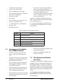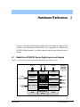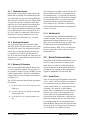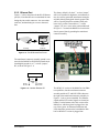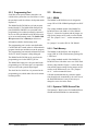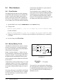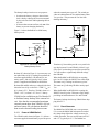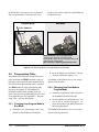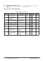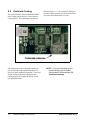
1
RabbitCore RCM2100 Series C-Programmable Modules with Ethernet User’s Manual 019–0091 • 010315–A RabbitCore RCM2100 Series: User’s Manual Part Number 019–0091, Rev 010315–A • Printed in U.S.A. © 2001 Z-World, Inc. • All rights reserved. Z-World reserves the right to make changes and improvements to its products without providing notice. Notice to Users Z-World products are not authorized for use as critical components in life-support devices or systems unless a specific written agreement regarding such intended use is entered into between the customer and Rabbit Semiconductor prior to use. Lifesupport devices or systems are devices or systems intended for surgical implantation into the body or to sustain life, and whose failure to perform, when properly used in accordance with instructions for use provided in the labeling and user’s manual, can be reasonably expected to result in significant injury. No complex software or hardware system is perfect. Bugs are always present in a system of any size. In order to prevent danger to life or property, it is there responsibility of the system designer to incorporate redundant protective mechanisms appropriate to the risk involved. Trademarks Rabbit 2000 is a trademark of Rabbit Semiconductor. Dynamic C is a registered trademark of Z-World, Inc. Z80/Z180 is a trademark of Zilog, Inc. ii Rabbit Semiconductor Z-World, Inc. 2932 Spafford Street Davis, California 95616-6800 USA 2900 Spafford Street Davis, California 95616-6800 USA Telephone: (530) 757-8400 Fax: (530) 757-8402 Telephone: (530) 757-3737 Fax: (530) 753-5141 www.rabbitsemiconductor.com www.zworld.com RabbitCore RCM2100 Series Table of Contents 1 2 Introduction 1-1 1.1 1.2 1.3 1.4 1-1 1-2 1-2 1-3 RabbitCore RCM2100 Series Features . . . . . . . . . . . . . . . . . . . . . . . . . . . . Advantages of the RabbitCore RCM2100 Series. . . . . . . . . . . . . . . . . . . . . Development and Evaluation Tools . . . . . . . . . . . . . . . . . . . . . . . . . . . . . . . How to Use This Manual . . . . . . . . . . . . . . . . . . . . . . . . . . . . . . . . . . . . . . . Hardware Reference 2-1 2.1 RabbitCore RCM2100 Series Digital Inputs and Outputs . . . . . . . . . . . . . . 2.1.1 Dedicated Inputs . . . . . . . . . . . . . . . . . . . . . . . . . . . . . . . . . . . . . . . . . . . . 2.1.2 Dedicated Outputs . . . . . . . . . . . . . . . . . . . . . . . . . . . . . . . . . . . . . . . . . . . 2.1.3 Memory I/O Interface . . . . . . . . . . . . . . . . . . . . . . . . . . . . . . . . . . . . . . . . . 2.1.4 Additional I/0 . . . . . . . . . . . . . . . . . . . . . . . . . . . . . . . . . . . . . . . . . . . . . . . . 2.2 Serial Communication . . . . . . . . . . . . . . . . . . . . . . . . . . . . . . . . . . . . . . . . . 2.2.1 Serial Ports . . . . . . . . . . . . . . . . . . . . . . . . . . . . . . . . . . . . . . . . . . . . . . . . . 2.2.2 Ethernet Port . . . . . . . . . . . . . . . . . . . . . . . . . . . . . . . . . . . . . . . . . . . . . . . . 2.2.3 Programming Port . . . . . . . . . . . . . . . . . . . . . . . . . . . . . . . . . . . . . . . . . . . 2.3 Memory . . . . . . . . . . . . . . . . . . . . . . . . . . . . . . . . . . . . . . . . . . . . . . . . . . . . 2.3.1 SRAM . . . . . . . . . . . . . . . . . . . . . . . . . . . . . . . . . . . . . . . . . . . . . . . . . . . . . . 2.3.2 Flash Memory . . . . . . . . . . . . . . . . . . . . . . . . . . . . . . . . . . . . . . . . . . . . . . . 2.3.3 Dynamic C BIOS Source Files . . . . . . . . . . . . . . . . . . . . . . . . . . . . . . . . . 2-1 2-6 2-6 2-6 2-6 2-6 2-6 2-7 2-8 2-8 2-8 2-8 2-8 User’s Manual iii 2.4 Other Hardware. . . . . . . . . . . . . . . . . . . . . . . . . . . . . . . . . . . . . . . . . . . . . . 2-10 2.4.1 Clock Doubler . . . . . . . . . . . . . . . . . . . . . . . . . . . . . . . . . . . . . . . . . . . . . . 2-10 2.4.2 Backup Battery Circuit. . . . . . . . . . . . . . . . . . . . . . . . . . . . . . . . . . . . . . . 2-10 2.5 Programming Cable . . . . . . . . . . . . . . . . . . . . . . . . . . . . . . . . . . . . . . . . . . 2-12 2.5.1 Changing from Program Mode to Run Mode. . . . . . . . . . . . . . . . . . . . 2-12 2.5.2 Changing from Run Mode to Program Mode. . . . . . . . . . . . . . . . . . . . 2-12 3 Software Reference 3-1 3.1 More About Dynamic C . . . . . . . . . . . . . . . . . . . . . . . . . . . . . . . . . . . . . . . . . 3-1 3.1.1 Operating System Framework . . . . . . . . . . . . . . . . . . . . . . . . . . . . . . . . . 3-2 3.1.2 Using Dynamic C . . . . . . . . . . . . . . . . . . . . . . . . . . . . . . . . . . . . . . . . . . . . 3-2 3.2 Dynamic C Libraries . . . . . . . . . . . . . . . . . . . . . . . . . . . . . . . . . . . . . . . . . . . 3-3 3.2.1 I/O . . . . . . . . . . . . . . . . . . . . . . . . . . . . . . . . . . . . . . . . . . . . . . . . . . . . . . . . . 3-3 3.2.2 Serial Communication Drivers . . . . . . . . . . . . . . . . . . . . . . . . . . . . . . . . . 3-3 3.2.3 TCP/IP Drivers . . . . . . . . . . . . . . . . . . . . . . . . . . . . . . . . . . . . . . . . . . . . . . 3-4 3.3 Sample Programs . . . . . . . . . . . . . . . . . . . . . . . . . . . . . . . . . . . . . . . . . . . . . 3-4 3.4 Upgrading Dynamic C . . . . . . . . . . . . . . . . . . . . . . . . . . . . . . . . . . . . . . . . . . 3-5 3.4.1 Upgrades . . . . . . . . . . . . . . . . . . . . . . . . . . . . . . . . . . . . . . . . . . . . . . . . . . . 3-5 A RabbitCore RCM2100 Specifications A-1 A.1 Electrical and Mechanical Characteristics. . . . . . . . . . . . . . . . . . . . . . . . . . A-2 A.1.1 Headers . . . . . . . . . . . . . . . . . . . . . . . . . . . . . . . . . . . . . . . . . . . . . . . . . . . . A-4 A.1.2 Physical Mounting . . . . . . . . . . . . . . . . . . . . . . . . . . . . . . . . . . . . . . . . . . . A-4 A.2 Bus Loading . . . . . . . . . . . . . . . . . . . . . . . . . . . . . . . . . . . . . . . . . . . . . . . . A-4 A.3 Rabbit 2000 DC Characteristics . . . . . . . . . . . . . . . . . . . . . . . . . . . . . . . . . A-6 A.4 I/O Buffer Sourcing and Sinking Limit . . . . . . . . . . . . . . . . . . . . . . . . . . . . . A-7 A.5 Conformal Coating . . . . . . . . . . . . . . . . . . . . . . . . . . . . . . . . . . . . . . . . . . . A-8 B Power Supply B-1 B.1 Power Supplies . . . . . . . . . . . . . . . . . . . . . . . . . . . . . . . . . . . . . . . . . . . . . . .B-1 B.2 Chip Select Circuit. . . . . . . . . . . . . . . . . . . . . . . . . . . . . . . . . . . . . . . . . . . . .B-1 C Programming Cable C-1 D Sample Circuits D-1 D.1 D.2 D.3 D.4 D-2 D-3 D-4 D-5 iv RS-232/RS-485 Serial Communication. . . . . . . . . . . . . . . . . . . . . . . . . . . . Keypad and LCD Connections . . . . . . . . . . . . . . . . . . . . . . . . . . . . . . . . . . External Memory . . . . . . . . . . . . . . . . . . . . . . . . . . . . . . . . . . . . . . . . . . . . . D/A Converter . . . . . . . . . . . . . . . . . . . . . . . . . . . . . . . . . . . . . . . . . . . . . . . RabbitCore RCM2100 Series E External Interrupts E-1 E.1 E.2 E.3 E.4 E-2 E-3 E-4 E-4 Use of External Interrupts. . . . . . . . . . . . . . . . . . . . . . . . . . . . . . . . . . . . . . . Single-Interrupt Request . . . . . . . . . . . . . . . . . . . . . . . . . . . . . . . . . . . . . . . OR’ed Interrupt Request . . . . . . . . . . . . . . . . . . . . . . . . . . . . . . . . . . . . . . . Generating Interrupts With the RealTek Chip . . . . . . . . . . . . . . . . . . . . . . . Index Schematics User’s Manual v vi RabbitCore RCM2100 Series Introduction 1 The RabbitCore RCM2100 series is a family of microprocessor modules designed to be the heart of embedded control systems. In addition to the array of I/O and addressing available on other Z-World products, the RCM2100 series offers an optional integrated Ethernet port. These modules permit LAN and Internet-enabled systems to be built as easily as serial communicationsonly systems. Data processing is done by a Rabbit 2000 microprocessor operating at 22 MHz. The RabbitCore RCM2100 series has a Rabbit 2000 microprocessor, a static RAM, up to two flash memory chips, two quartz crystals (main oscillator and timekeeping), and the circuitry necessary for reset and management of battery backup of the Rabbit 2000’s internal real-time clock and the static RAM. Two 40-pin headers bring out the Rabbit 2000 I/O bus, address lines, data lines, parallel ports, and serial ports. The RabbitCore RCM2100 series receives its +5 V power from the user board on which it is mounted. The RabbitCore RCM2100 series can interface with User’s Manual all kinds of CMOS-compatible digital devices through the user board. 1.1 RabbitCore RCM2100 Series Features • Small size: 2.0" × 3.5" × 0.80" (51 mm × 89 mm × 20 mm) • Microprocessor: Rabbit 2000 running at 22.1 MHz • 34 CMOS-compatible parallel I/O lines grouped in five 8-bit ports (shared with serial ports) • 8 data lines (BD0–BD7) Introduction 1–1 • 13 address lines (BA0–BA12) • I/0 read, write, buffer enable • Status, watchdog and clock outputs • Two startup mode inputs for booting and master/slave configuration • External reset input • Reset output • Five 8-bit timers, two 10-bit timers; five timers are cascadable in pairs • 2 × 256K flash memory, 512K SRAM • Real-time clock • Watchdog supervisor • Provision for customer-supplied backup battery via connections on header J2 • Four CMOS-compatible serial ports: maximum asynchronous baud rate of 690,625 bps, maximum synchronous baud rate of 5.52 Mbps. Two ports are configurable as clocked ports. Appendix A, “RabbitCore RCM2100 Specifications,” provides detailed specifications for the RabbitCore RCM2100 series. Five versions of the RabbitCore RCM2100 series are available. Their standard features are summarized in Table 1. Table 1: RabbitCore RCM2100 Series Features Model 1.2 1–2 Features RCM2100 Full-featured module RCM2110 RCM2100 with 128K SRAM, 256K flash memory RCM2115 RCM2110 without RJ-45 plug/transformer RCM2120 RCM2100 without Ethernet RCM2130 RCM2110 without Ethernet Advantages of the RabbitCore RCM2100 Series • Models with and without Ethernet for flexible production options. • Small size and identical footprint and pinout for all models. • Fast time to market using a fully engineered, “ready to run” microprocessor core. • Competitive pricing when compared with the alternative of purchasing and assembling individual components. • Easy C-language program development and debugging, including rapid production loading of programs. • Generous memory size allows large programs with tens of thousands of lines of code, and substantial data storage. A complete Development Kit, including a Prototyping Board, accessory components and Dynamic C development software, is available to accompany the RCM2100 module. The Development Kit puts together the essentials you need to design an embedded microprocessor-based system rapidly and efficiently. • Integrated Ethernet port (on selected models) for network connectivity, royalty-free TCP/IP software. See the RabbitCore RCM2100 Series Getting Started Manual for complete information on the Development Kit. Introduction 1.3 Development and Evaluation Tools RabbitCore RCM2100 Series 1.4 How to Use This Manual This user’s manual is intended to give users detailed information on the RCM2100 series modules. It does not contain detailed information on the Dynamic C development environment or the TCP/IP software support for the integrated Ethernet port. Most users will want more detailed information on some or all of these topics in order to put the RCM2100 module to effective use. 1.4.1 Additional Product Information Introductory information about the RabbitCore RCM2100 series and its associated Development Kit and Prototyping Board will be found in the printed RabbitCore RCM2100 Series Getting Started Manual, which is also provided on the accompanying CD-ROM in both HTML and Adobe PDF format. We recommend that any users unfamiliar with Z-World products, or those who will be using the prototyping board for initial evaluation and development, begin with at least a read-through of the Getting Started manual. 1.4.2 Additional Reference Information In addition to the product-specific information contained in the RabbitCore RCM2100 Series Getting Started and User’s Manual, several higher level reference manuals are provided in HTML and PDF form on the accompanying CD-ROM. Advanced users will find these references valuable in developing systems based on the RCM2100 series modules: • Dynamic C Premier User’s Manual • Introduction to TCP/IP • TCP/IP Function Reference • Rabbit 2000 Microprocessor User’s Manual 1.4.3 Using Online Documentation We provide the bulk of our user and reference documentation in two electronic formats, HTML and Adobe PDF. We do this for several reasons. We believe that providing all users with our complete library of product and reference manuals is a useful convenience. However, printed manuals are expensive to print, stock, and ship. Rather than include and charge for manuals that every user may not want, or provide only product-specific manuals, we choose to provide our complete documentation and reference library in electronic form with every Development Kit and with our Dynamic C development environment. NOTE: The most current version of Adobe Acrobat Reader can always be downloaded from Adobe’s web site at http://www.adobe.com. We recommend that you use version 4.0 or later. Providing this documentation in electronic form saves an enormous amount of paper by not printing copies of manuals that users don’t need. It reduces the number of outdated manuals we have to discard from stock as well, and it makes providing a complete library of manuals an almost cost-free option. For one-time or infrequent reference, electronic documents are more convenient than printed ones— after all, they aren’t taking up shelf or desk space! Finding Online Documents The online documentation is installed along with Dynamic C, and an icon for the documentation menu is placed on the workstation’s desktop. Double-click this icon to reach the menu. If the icon is missing, use your browser to find and load default.htm in the docs folder, found in the Dynamic C installation folder. The latest versions of all documents are always available for free, unregistered download from our Web sites as well. User’s Manual Introduction 1–3 Printing Electronic Manuals We recognize that many users prefer printed manuals for some uses. Users can easily print all or parts of those manuals provided in electronic form. The following guidelines may be helpful: 1–4 • Print from the Adobe PDF versions of the files, not the HTML versions. • Print only the sections you will need to refer to more than once. • Print manuals overnight, when appropriate, to keep from tying up shared resources during the work day. Introduction • If your printer supports duplex printing, print pages double-sided to save paper and increase convenience. • If you do not have a suitable printer or do not want to print the manual yourself, most retail copy shops (e.g., Kinkos, AlphaGraphics, CopyMax) will print the manual from the PDF file and bind it for a reasonable charge—about what we would have to charge for a printed and bound manual. RabbitCore RCM2100 Series Hardware Reference 2 Chapter 2 describes the hardware components and principal hardware subsystems of the RabbitCore RCM2100 series. Appendix A, “RabbitCore RCM2100 Specifications,” provides complete physical and electrical specifications. 2.1 RabbitCore RCM2100 Series Digital Inputs and Outputs Figure 2–1 shows the subsystems designed into the RabbitCore RCM2100 series. PA0PA7 4x CMOS synchronous/ asynchronous PCLK RESET WDO PB0 PB5 PB6 PB7 PD0PD7 Port A Port B Port D Serial Ports (Port C) RABBIT Port E Programming Port 2000 Misc. Outputs Real-Time Clock Watchdog 7 Timers Slave Port Clock Doubler RAM Backup Battery Support Address Lines I/O Control Data Lines Ethernet: PD4PD7 PE2, PE6 PE0PE7 BA0BA12 IORD IOWR BUFEN BD0BD7 Flash Figure 2–1: Rabbit Subsystems User’s Manual Hardware Reference 2–1 The RabbitCore RCM2100 series has 40 parallel I/O lines grouped in five 8-bit ports available on headers J1 and J2. The 24 bidirectional I/O lines are located on pins PA0–PA7, PD0–PD7, and PE0–PE7. The pinouts for headers J1 and J2 are shown in Figure 2–2. J1 VCC PCLK PA6 PA4 PA2 PA0 BA11 BA9 BA7 BA5 BA3 BA1 PC0 PC2 PC4 PC6-TXA PD0 PD2 PD4 PD6 J2 GND PA7 PA5 PA3 PA1 BA12 BA10 BA8 BA6 BA4 BA2 BA0 PC1 PC3 PC5 PC7-RXA PD1 PD3 PD5 PD7 PB0 PB2 PB4 PB6 GND BD6 BD4 BD2 BD0 PE6 PE4 PE2 PE0 VCC VRAM SMODE1 /RESET STATUS /BIORD GND PB1-CLKA PB3 PB5 PB7 BD7 BD5 BD3 BD1 PE7 PE5 PE3 PE1 GND VBAT /WDO SMODE0 /RES_IN /BIOWR /BBUFEN VCC Note: These pinouts are as seen on the Bottom Side of the module. Figure 2–2: RabbitCore RCM2100 Series I/O Pinouts The ports on the Rabbit 2000 microprocessor used in the RabbitCore RCM2100 series are configurable, and so the factory defaults can be reconfigured. Table 1 lists the Rabbit 2000 factory defaults and the alternate configurations. clock on Serial Port B and Serial Port A of the Rabbit microprocessor. Pins PD4 and PD6 can be programmed to be optional serial outputs for Serial Ports B and A. PD5 and PD7 can be used as alternate serial inputs by Serial Ports B and A. As shown in Table 1, pins PA0–PA7 can be used to allow the Rabbit 2000 to be a slave to another processor. PE0, PE1, PE4, and PE5 can be used as external interrupts INT0A, INT1A, INT0B, and INT1B. Pins PB0 and PB1 can be used to access the The Ethernet-enabled versions of the RCM2100 do not have 0 Ω resistors (jumpers) installed at R21, R24, and R35–R38, which allows PE6, PE2, and PD4–PD7 to connect to the RealTek Ethernet chip that is stuffed on those versions. 2–2 Hardware Reference RabbitCore RCM2100 Series Table 1: RabbitCore RCM2100 Series Pinout Configurations Header J1 Pin Pin Name 1 VCC 2 GND Default Use Alternate Use 3 PCLK Output (Internal Clock) Output 4–11 PA[7:0] Parallel I/O Slave port data bus SD0–SD7 12–24 BA[12:0] Output 25 PC0 Output TXD 26 PC1 Input RXD 27 PC2 Output TXC 28 PC3 Input RXC 29 PC4 Output TXB 30 PC5 Input RXB 31 PC6 Output TXA 32 PC7 Input RXA 33–36 PD[0:3] 37 PD4 38 PD5 39 40 User’s Manual Notes Disable by removing R20; can also be disabled in software (Dynamic C 7.03 and later versions) Buffered Rabbit 2000 address bus Connected to programming port 16 mA sourcing and sinking current at full AC switching speed ATXB output Ethernet chip RSTDRV ARXB input Ethernet chip BD5 PD6 ATXA output Ethernet chip BD6 PD7 ARXA input Ethernet chip BD7 Bitwise or parallel programmable I/O, can be driven or open-drain output Hardware Reference 2–3 Table 1: RabbitCore RCM2100 Series Pinout Configurations (continued) Pin Pin Name Default Use Alternate Use 1 PB0 Input Serial port clock CLKB 2 PB1 Input Serial port clock CLKA 3 PB2 Input Slave port write /SWR 4 PB3 Input Slave port read /SRD 5 PB4 Input SA0 6 PB5 Input SA1 7 PB6 Output 8 PB7 Output 9, 26, 39 GND 10–17 BD[7:0] 18 PE7 I7 output or slave port chip select /SCS 19 PE6 I6 output 20 PE5 I5 output or INT1B input 21 PE4 22 PE3 I3 output 23 PE2 I2 output 24 PE1 I1 output or INT1A input 25 PE0 I0 output or INT0A input 27, 40 VCC 28 VBAT 3 V battery input 29 VRAM 2.1 V output 30 /WDO Output (Watchdog output) Notes CLKA is connected to programming port (header J5, pin 3) Header J2 Slave port address lines 2–4 Hardware Reference Slave port attention line /SLAVEATTN Buffered Rabbit 2000 data bus Input/Output Bitwise or parallel programmable I/O Ethernet chip IOWB I4 output or INT0B input Ethernet chip IORB 100 µA maximum current draw May also be used to output a 30 µs pulse Outputs a pulse when the internal watchdog times out RabbitCore RCM2100 Series Table 1: RabbitCore RCM2100 Series Pinout Configurations (continued) Pin Pin Name Default Use Alternate Use (0,0)—start executing at address zero Header J2 31–32 SMODE1, SMODE0 SMODE0 =1, SMODE1 =1 Cold boot from asynchronous serial port A at 2400 bps (programming cable connected) 33 /RESET Reset output 34 /RES_IN Reset input 35 STATUS Output (Status) 36 /BIOWR Output (I/O buffer write strobe) 37 /BIORD Output (I/O buffered strobe) 38 /BUFEN Output (I/O buffer enable) User’s Manual Notes No programming cable attached (0,1)—cold boot from slave port (1,0)—cold boot from clocked serial port A With programming cable attached Output Hardware Reference 2–5 2.1.1 Dedicated Inputs PB0 and PB1 are designated as inputs because the Rabbit 2000 is operating in an asynchronous mode. Four of the input-only pins are located on PB2–PB5. These pins are used for the slave port. PB2 and PB3 are slave write and slave read strobes, while PB4 and PB5 serve as slave address lines SA0 and SA1, and are used to access the slave registers (SD0– SD7), which is the alternate assignment for parallel port A. When Port C is used as a parallel port, PC1, PC3, PC5, and PC7 are inputs only. These pins can alternately be selectively enabled to serve as the serial data inputs for Serial Ports D, C, B, and A. 2.1.2 Dedicated Outputs Two of the output-only pins are located on PB6– PB7. PB7 can also be used with the slave port as the /SLAVEATTN output. This configuration signifies that the slave is requesting attention from the master. When Port C is used as a parallel port, PC0, PC2, PC4 and PC6 are outputs only. These pins can alternately serve as the serial data outputs for Serial Ports D, C, B, and A. 2.1.3 Memory I/O Interface Thirteen of the Rabbit 2000 buffered address lines (A0–A12) and all the buffered data lines (D0–D7) are available as outputs. I/0 write (/IOWR), I/0 read (/IORD), buffer enable (/BUFEN), and Watchdog Output (/WDO) are also available for interfacing to external devices. The STATUS output has three different programmable functions: 1. It can be driven low on the first op code fetch cycle. 2. It can be driven low during an interrupt acknowledge cycle. 3. It can also serve as a general-purpose output. 2–6 Hardware Reference The output clock is available on the PCLK pin. The primary function of PCLK is as a peripheral clock or a peripheral clock ÷ 2, but PCLK can instead be used as a digital output. PCLK can also be disabled by removing R20 if there is a need to reduce radiated emissions. Removing R20 will disable the PCLK output on pin 3 of header J1. Alternatively, PCLK can be disabled in software using Dynamic C version 7.03 or later. 2.1.4 Additional I/0 Two status mode pins, SMODE0 and SMODE1, are available as inputs. The logic state of these two pins determines the startup procedure after a reset. /RES_IN is an external input used to reset the Rabbit 2000 microprocessor and the RabbitCore RCM2100 memory. /RES_OUT is an output from the reset circuitry that can be used to reset other peripheral devices. 2.2 Serial Communication The RabbitCore RCM2100 board does not have an RS-232 or an RS-485 transceiver directly on the board. However, an RS-232 or RS-485 interface may be incorporated on the board the RCM2100 is mounted on. For example, the Prototyping Board supports a standard RS-232 transceiver chip. 2.2.1 Serial Ports There are four serial ports designated as Serial Ports A, B, C, and D. All four serial ports can operate in an asynchronous mode up to the baud rate of the system clock divided by 32. An asynchronous port can handle 7 or 8 data bits. A 9th bit address scheme, where an additional bit is sent to mark the first byte of a message, is also supported. Serial Ports A and B can be operated alternately in the clocked serial mode. In this mode, a clock line synchronously clocks the data in or out. Either of the two communicating devices can supply the clock. When the Rabbit 2000 provides the clock, the baud rate can be up to 1/4 of the system clock frequency, or 5.52 Mbps for a 22.1 MHz clock speed. RabbitCore RCM2100 Series 2.2.2 Ethernet Port Figure 2–3 shows the pinout for the RJ-45 Ethernet port (J4). Note that there are two standards for numbering the pins on this connector—the convention used here, and numbering in reverse to that used here. ETHERNET 1 8 1. 2. 3. 6. RJ-45 Plug The factory default is for the 0 Ω resistor “jumper” at R5 to be installed. In high-noise environments, it may be useful to ground the transformer/connector assembly directly through the chassis ground. This will be especially helpful to minimize EMI problems. Once you have removed the 0 Ω resistor “jumper,” R5, use a screw in the position indicated in Figure 2–5 to attach the RabbitCore board to the chassis ground, thereby grounding the transformer/ connector assembly. E_Tx+ E_Tx E_Rx+ E_Rx RJ-45 Jack Figure 2–3: RJ-45 Ethernet Port Pinout The transformer/connector assembly ground is connected to the RabbitCore RCM2100 printed circuit board digital ground via a 0 Ω resistor “jumper,” R5, as shown in Figure 2–4. RJ-45 Ethernet Plug R5 Board Ground Chassis Ground Figure 2–4: Isolation Resistor R5 User’s Manual Figure 2–5: R5 and Chassis Ground Locations The RCM2115 version of the RabbitCore has Ethernet capabilities, but the transformer/connector assembly and the ACT and LNK LEDs (shown to the right of the transformer/connector assembly in Figure 2–5 above) are not installed. The Ethernet signals and the LED control signals are located on header J3 on the bottom side of this version of the RabbitCore, which may then be plugged in to the rest of the system. An Ethernet transformer and LEDs should be present on the board that the RabbitCore RCM2115 version is plugged into. Hardware Reference 2–7 2.2.3 Programming Port 2.3 Serial Port A has special features that allow it to cold-boot the system after reset. Serial Port A is also the port that is used for software development under Dynamic C. 2.3.1 SRAM The RabbitCore RCM2100 has a 10-pin program header labeled J5. The Rabbit 2000 startup-mode pins (SMODE0, SMODE1) are presented to the programming port so that an externally connected device can force the RabbitCore RCM2100 to start up in an external bootstrap mode. The Rabbit 2000 Microprocessor User’s Manual provides more information related to the bootstrap mode. The programming port is used to start the RabbitCore RCM2100 in a mode where it will download a program from the port and then execute the program. The programming port transmits information to and from a PC while a program is being debugged. The RabbitCore RCM2100 can be reset from the programming port via the /RESET_IN line. The Rabbit 2000 status pin is also presented to the programming port. The status pin is an output that can be used to send a general digital signal. The clock line for Serial Port A is presented to the programming port, which makes fast serial communication possible. Memory The RabbitCore RCM2100 series is designed to accept 32K to 512K of SRAM packaged in an SOIC case. The existing standard models of the RabbitCore RCM2100 come with 128K or 512K of SRAM. Figure 2–6 shows the locations and the jumper settings for the jumpers at JP1 used to set the SRAM size. The “jumpers” are 0 Ω surface-mounted resistors. No “jumpers” are used at JP1 for 32K SRAM. 2.3.2 Flash Memory The RabbitCore RCM2100 is also designed to accept 128K to 512K of flash memory packaged in a TSOP case. The existing standard models of the RabbitCore RCM2100 come with either one or two 256K flash memory chips installed. Figure 2–6 shows the locations and the jumper settings for the jumpers at JP2 used to set the flash memory size. The “jumpers” are 0 Ω surface-mounted resistors. Z-World recommends that any customer applications should not be constrained by the sector size of the flash EPROM since it may be necessary to change the sector size in the future. 2.3.3 Dynamic C BIOS Source Files The Dynamic C BIOS source files handle different SRAM and flash EPROM sizes automatically. 2–8 Hardware Reference RabbitCore RCM2100 Series FD RCM2100 Factory Default SRAM Flash Memory 128K/256K FD 512K JP1 JP1 3 2 1 FD 128K 1 2 JP3 3 1 2 JP3 3 3 2 1 JP2 512K JP2 J2 J1 JP2 U11 Flash EPROM JP1 U10 Flash EPROM J3 U12 JP3 SRAM Bottom Side Figure 2–6: RabbitCore RCM2100 SRAM and Flash Memory Sizes—Jumper Settings User’s Manual Hardware Reference 2–9 2.4 Other Hardware 2.4.1 Clock Doubler The RabbitCore RCM2100 series takes advantage of the Rabbit 2000 microprocessor’s internal clock doubler. A built-in clock doubler allows half-frequency crystals to be used to reduce radiated emissions. The 22.1 MHz frequency is generated using an 11.05 MHz crystal. The clock doubler is disabled automatically in the BIOS for crystals with a frequency above 12.9 MHz. The clock doubler may be disabled if 22.1 MHz clock speeds are not required. Disabling the Rabbit 2000 microprocessor’s internal clock will reduce power consumption and further reduce radiated emissions. The clock doubler is disabled with a simple change to the BIOS as described below. 1. Open the BIOS source code file, RABBITBIOS.C in the BIOS directory. 2. Change the line #define CLOCK_DOUBLED 1 // set to 1 to double the clock if XTAL<=12.9MHz, to read as follows. #define CLOCK_DOUBLED 0 // set to 1 to double the clock if XTAL<=12.9MHz, 3. Change the serial baud rate to 57,600 bps when the RabbitCore RCM2100 series is operated at 11.05 MHz. 4. Save the change using File > Save. 2.4.2 Backup Battery Circuit The RabbitCore RCM2100 does not have a battery, but there is provision for a customer-supplied battery to back up SRAM and keep the internal Rabbit 2000 real-time clock running. Header J2, shown in Figure 2–7, allows access to the external battery. This header makes it possible to connect an external 3 V power supply. This allows the SRAM and the internal Rabbit 2000 real-time clock to retain data with the RabbitCore RCM2100 powered down. A lithium battery with a nominal voltage of 3 V and a minimum capacity of 165 mA·h is recommended. A lithium battery is strongly recommended because of its nearly constant nominal voltage over most of its life. The drain on the battery by the RabbitCore RCM2100 is typically 16 µA when no other power is supplied. If a 950 mA·h battery is used, the battery can last more than 6 years: 2–10 Hardware Reference VCC 27 26 GND VRAM 29 28 VBAT External Battery Figure 2–7: External Battery Connections at Header J2 950 mA·h ------------------------ = 6.8 years. 16 µA The actual life in your application will depend on the current drawn by components not on the RabbitCore RCM2100 and the storage capacity of the battery. Note that the shelf life of a lithium battery is ultimately 10 years. RabbitCore RCM2100 Series The battery-backup circuit serves two purposes: • It reduces the battery voltage to the real-time clock, thereby reducing the current consumed by the real-time clock and lengthening the battery life. when the external power goes off. The switch provides an isolation between Vcc and the battery when Vcc goes low. This prevents the Vcc line from draining the battery. • It ensures that current can flow only out of the battery to prevent charging the battery. VCC Figure 2–8 shows the RabbitCore 2000 battery backup circuit. R12 VRAM 0W Q2 FDV302P R14 VRAM 10 kW MMBT5088LT1 Q1 C6 VBAT R7 R9 1.3 kW 220 kW 100 nF R8 2 MW Figure 2–8: RabbitCore RCM2100 Battery Backup Circuit Resistor R7, shown in Figure 2–8, prevents any catastrophic failure of Q1 by limiting current from the customer-supplied battery. VRAM and Vcc are nearly equal (<100 mV, typically 10 mV) when power is supplied to the RabbitCore RCM2100. Resistors R8 and R9 make up a voltage divider that biases the base of Q1 to about 0.9 × VBAT. VBE on Q1 is about 0.55 V. Therefore, VRAM is about 0.9 × VBAT - 0.55 V, or about 2.15 V for a 3 V battery. VRAM is also available on pin 29 of header J2 to facilitate battery backup of the external circuit. Note that the recommended maximum external current draw from VRAM is 100 µA, and new battery-life calculations should be done to take external loading into account. 2.4.2.1 Power to VRAM Switch The VRAM switch, shown in Figure 2–9, allows a customer-supplied external battery to provide power User’s Manual /RESET R15 Q3 MMBT3904 22 kW Figure 2–9: VRAM Switch Transistor Q2 is needed to provide a very small voltage drop between Vcc and VRAM (<100 mV, typically 10 mV) so that the processor lines powered by Vcc will not have a significantly different voltage than VRAM. When the RabbitCore RCM2100 is not resetting (pin 2 on U3 is high), the /RESET line will be high. This turns on Q3, causing its collector to go low. This turns on Q2, allowing VRAM to nearly equal Vcc. When the RabbitCore RCM2100 is resetting, the /RESET line will go low. This turns off Q2 and Q3, providing an isolation between Vcc and VRAM. The battery backup circuit keeps VRAM from dropping below 2 V. 2.4.2.2 Reset Generator The RabbitCore RCM2100 uses a reset generator, U2, to reset the Rabbit 2000 microprocessor when the voltage drops below the voltage necessary for reliable operation. The reset occurs between 4.50 V and 4.75 V, typically 4.63 V. The RabbitCore Hardware Reference 2–11 RCM2100 has a reset output, pin 33 on header J2. The reset generator has a reset input, pin 34 on header J2, that can be used to force the RabbitCore RCM2100 to reset. Run Mode Program Mode To PC COM port RESET RabbitCore when changing mode: Short out pins 36 and 39 on header J2, OR Press RESET button (if using Prototyping Board), OR Remove, then reapply power after removing or attaching programming cable. Figure 2–10: Switching Between Program Mode and Run Mode 2.5 Programming Cable The RabbitCore RCM2100 is automatically in program mode when the PROG connector on the programming cable is attached, and is automatically in run mode when no programming cable is attached. The DIAG connector of the programming cable may be used on header J5 of the RabbitCore RCM2100 with the board operating in the run mode. This allows the programming port to be used as an application port. See Appendix C, “Programming Cable,” for more information. 2.5.1 Changing from Program Mode to Run Mode 1. 2–12 Disconnect the programming cable from header J5 of the RabbitCore RCM2100. Hardware Reference 2. Reset the RabbitCore RCM2100. You may do this as explained in Figure 2–10. The RabbitCore RCM2100 series is now ready to operate in the run mode. 2.5.2 Changing from Run Mode to Program Mode 1. Attach the programming cable to header J3 on the RabbitCore RCM2100 series. 2. Reset the RabbitCore RCM2100 series. You may do this as explained in Figure 2–10. shows the location of the RESET button on the Prototyping Board. The RabbitCore RCM2100 series is now ready to operate in the program mode. RabbitCore RCM2100 Series Software Reference 3 Dynamic C Premier is an integrated development system for writing embedded software. It runs on an IBM-compatible PC and is designed for use with Z-World controllers and other controllers based on the Rabbit microprocessor. Chapter 3 provides the libraries, function calls, and sample programs related to the RabbitCore RCM2100. 3.1 More About Dynamic C Dynamic C has been in use worldwide since 1989. It is specially designed for programming embedded systems, and features quick compile and interactive debugging in the real environment. A complete reference guide to Dynamic C is contained in the Dynamic C Premier User’s Manual. Dynamic C for Rabbit 2000™ processors uses the standard Rabbit programming interface. This is a 10-pin connector that connects to the Rabbit 2000 serial port A. It is possible to reset and cold-boot a Rabbit processor via the programming port. No software needs to be present in the target system. More details are available in the Rabbit 2000 Microprocessor User’s Manual. User’s Manual Dynamic C cold-boots the target system and compiles the BIOS. The BIOS is a basic program of a few thousand bytes in length that provides the debugging and communication facilities that Dynamic C needs. Once the BIOS has been compiled, the user can compile his own program and test it. If the user program stops running, a new cold boot and BIOS compile can be done at any time. Dynamic C does not use include files, rather it has libraries that are used for the same purpose, that is, to supply functions and function prototypes to programs before they are compiled. Dynamic C supports assembly language, either as separate functions or as fragments embedded in C programs. Interrupt routines may be written in Dynamic C or in assembly language. Software Reference 3–1 3.1.1 Operating System Framework Dynamic C does not include an operating system in the usual sense of a complex software system that is resident in memory. The user has complete control of what is loaded as a part of his program, other than those routines that support loading and debugging (which are inactive at embedded run time). However, certain routines are very basic and normally should always be present and active. • Periodic interrupt routine. This interrupt routine is driven by the Rabbit periodic interrupt facility, and when enabled creates an interrupt every 16 ticks of the 32.768 kHz oscillator, or every 488 µs. This routine drives three long global variables that keep track of the time: SEC_TIMER, MS_TIMER, and TICK_TIMER that respectively count seconds, milliseconds, and 488 µs ticks. These variables are needed by some functions that measure time. The SEC_TIMER is set to seconds elapsed since 1 Jan 1980, and thus also keeps track of the time and date. The periodic interrupt routine must be disabled when the microprocessor enters sleepy mode and the processor clock is operating at 32.768 kHz. The interrupt routine cannot complete at this slow speed before the next tick of the periodic interrupt. In this situation, the hardware real-time clock can be read directly to provide the time. The periodic interrupt function also hits the hardware watchdog timer. Software or “virtual” watchdog timers are available in 3–2 Software Reference Dynamic C. See the Dynamic C Premier User’s Manual for more information. 3.1.2 Using Dynamic C You have a choice of doing your software development in the flash memory or in the static RAM. There are 512K or 256K bytes of flash memory and 512K or 128K bytes of SRAM. The advantage of working in RAM is to save wear on the flash, which is limited to about 100,000 writes. NOTE: Note that an application can be developed in RAM, but cannot run standalone from RAM after the programming cable is disconnected. All applications can only run from flash memory. NOTE: Do not depend on the flash memory sector size or type. Due to the volatility of the flash memory market, the RabbitCore RCM2100 and Dynamic C were designed to accommodate flash devices with various sector sizes. The disadvantage of using flash memory when debugging a program is that interrupts must be disabled for approximately 5 ms to 20 ms whenever a break point is set in the program. This can crash fast interrupt routines that are running while you stop at a break point or single-step the program. Flash memory or RAM is selected with the RabbitCore RCM2100 Series 3.2 Dynamic C Libraries With Dynamic C running, click File > Open, and select Lib. The following list of Dynamic C libraries will be displayed. The sample programs in the Dynamic C SAMPLES/RCM2100 directory provide further examples. 3.2.2 Serial Communication Drivers The Prototyping Board has room for an RS-232 chip for which the Rabbit serial library, RS232.LIB, provides a set of functions that send and receive entire blocks of data without yielding to other tasks, a set of single-user cofunctions that send and receive data but yield to other tasks, and a set of circular buffer functions. The naming convention is serXfn: ser—serial X—the port being used: A, B, C, or D fn - the function being implemented There is no unique library that is specific to the RabbitCore RCM2100. The functions in the above libraries are described in the Dynamic C Premier User’s Manual. For example, serBgetc() is the serial port B function getc(), which returns a character. 3.2.1 I/O The Rabbit serial functions are listed in the following groups. The RabbitCore RCM2100 was designed to interface with other systems, and so there are no drivers written specifically for the I/O. The general Dynamic C read and write functions allow you to customize the parallel I/O to meet your specific needs. For example, use WrPortI(PEDDR, &PEDDRShadow, 0x00); to set all the port E bits as inputs, or use WrPortI(PEDDR, &PEDDRShadow, 0xFF); to set all the port E bits as outputs. User’s Manual Open and Close Functions Non-Cofunction Blocking Input Functions Non-Cofunction Blocking Output Functions Single-User Cofunction Input Functions Single-User Cofunction Output Functions Circular Buffer Functions Software Reference 3–3 3.2.3 TCP/IP Drivers 3.3 Sample Programs The TCP/IP drivers are located in the TCPIP directory. Sample programs are provided in the Dynamic C Samples folder, which is shown below. Complete information on these libraries and the TCP/IP functions is provided in the Dynamic C Premier TCP/IP Function Reference Manual. The various folders contain specific sample programs that illustrate the use of the corresponding Dynamic C libraries. For example, the sample program PONG.C demonstrates the output to the Dynamic C STDIO window. Two folders contain sample programs that illustrate features unique to the RabbitCore RCM2100. • RCM2100—Demonstrates the basic operation and the Ethernet functionality of the RabbitCore RCM2100. • TCPIP—Demonstrates more advanced TCP/IP programming for Z-World’s Ethernet-enabled Rabbit-based boards. Follow the instructions included with the sample program to connect the RabbitCore RCM2100 and the other hardware identified in the instructions. To run a sample program, open it with the File menu (if it is not still open), compile it using the Compile menu, and then run it by selecting Run in the Run menu. The RabbitCore RCM2100 must be in Program Mode (see Section 2.5, “Programming Cable”) and must be connected to a PC using the programming cable. More complete information on Dynamic C is provided in the Dynamic C Premier User’s Manual. 3–4 Software Reference RabbitCore RCM2100 Series 3.4 Upgrading Dynamic C Dynamic C patches that focus on bug fixes are available from time to time. Check the Web sites • www.zworld.com/support/supportcenter.html • www.rabbitsemiconductor.com/support.html ply copy over an entire file since you may overwrite a bug fix; of course, you may copy over any programs you have written. Once you are sure the new patch works entirely to your satisfaction, you may retire the existing installation, but keep it available to handle legacy applications. or for the latest patches, workarounds, and bug fixes. The default installation of a patch or bug fix is to install the file in a directory (folder) different from that of the original Dynamic C installation. Z-World recommends using a different directory so that you can verify the operation of the patch without overwriting the existing Dynamic C installation. If you have made any changes to the BIOS or to libraries, or if you have programs in the old directory (folder), make these same changes to the BIOS or libraries in the new directory containing the patch. Do not sim- User’s Manual 3.4.1 Upgrades A special edition of Dynamic C, Dynamic C SE, is included on the CD that comes with the RabbitCore RCM2100 Development Kit, and has been customized with all the libraries and features needed to develop and run an application on the RabbitCore RCM2100. More advanced users who may need upgrades and additional capabilities for other Z-World products in the future are encouraged to consider the standard edition of Dynamic C Premier, which Z-World plans to fully supported with upgrades now and into the future. Software Reference 3–5 3–6 Software Reference RabbitCore RCM2100 Series RabbitCore RCM2100 Specifications A Appendix A provides the specifications for the RabbitCore RCM2100, and describes the conformal coating. User’s Manual RabbitCore RCM2100 Specifications A–1 A.1 Electrical and Mechanical Characteristics Figure A–1 shows the mechanical dimensions for the RabbitCore RCM2100. 3.50 0.120 dia 1.44 (37) (17) 0.66 (51) 2.00 (3) (6) (12) 0.25 (89) 0.48 0.166 dia (0,0) for Pin 1 coordinates (20) 0.80 (15) 0.61 (20) 0.80 (15) 0.61 (89) (14) J1 3.50 (13) J2 (14) 0.57 0.57 (13) 0.50 0.50 (4) 2.00 (51) Figure A–1: RabbitCore RCM2100 Dimensions Table A–1 provides the pin 1 locations for the RabbitCore RCM2100 headers viewed from the top side (as in Figure A–1). See Section A.1.1, “Headers,” for a “footprint” diagram. Table A–1: RabbitCore RCM2100 Header Pin 1 Locations Header A–2 Description Pin 1 (x,y) Coordinates (Inches) J1 RabbitCore RCM2100 subsystems (3.350, 1.730) J2 RabbitCore RCM2100 subsystems (1.000, 1.730) J3 Unisolated Ethernet signals (RCM2115 only) (0.225, 0.860) RabbitCore RCM2100 Specifications RabbitCore RCM2100 Series Table A–2 lists the electrical, mechanical, and environmental specifications for the RabbitCore RCM2100. Table A–2: RabbitCore RCM2100 Specifications Parameter Specification Board Size 2.00" × 3.50" × 0.80" (51 mm × 89 mm × 20 mm) Operating Temperature –40°C to +70°C Humidity 5% to 95%, noncondensing Input Voltage 4.75 V to 5.25 V DC Current 140 mA at 22.1 MHz, 5 V DC; 82 mA at 11.05 MHz, 5 V DC General-Purpose I/O 34 parallel I/0 lines grouped in five 8-bit ports (shared with serial ports): 20 configurable for I/O, 8 fixed inputs, 6 fixed outputs Memory, I/O Interface 13 address lines, 8 data lines, I/O read/write, buffer enable Additional Digital Inputs Startup mode (2 for master/slave), reset in Additional Digital Outputs Status, clock, watchdog out, reset out Ethernet Interface 10baseT Microprocessor Rabbit 2000 Clock 22.1 MHz SRAM 512K × 8, surface mount Flash Memory Two 256K × 8, surface mount Timers Five 8-bit timers cascadable in pairs, one 10-bit timer with 2 match registers that each have an interrupt Serial Ports Four CMOS-compatible ports. Two ports are configurable as clocked ports, one is configurable as RS-232 programming port. Serial Rate CMOS: maximum asynchronous 690,625 bps maximum synchronous 5.52 Mbps Slave Interface A slave port allows the RabbitCore RCM2100 to be used as an intelligent peripheral device slaved to a master processor, which may either be another Rabbit 2000 or any other type of processor Watchdog/Supervisor Yes Time/Date Clock Yes Socket Strip (for connection to headers J1 and J2) Pinrex 2x20, 2 mm pitch (PS2S-2X20GOB) Backup Battery Provision for user-supplied backup battery (2.85 V to 3.15 V) via connections on header J2 User’s Manual RabbitCore RCM2100 Specifications A–3 A.1.1 Headers The RabbitCore 2000 uses headers at J1, J2, and J3 for physical connection to other boards. J1 and J2 are 2 × 20 SMT headers with a 2 mm pin spacing. J3 is a 2 × 5 header with a 2 mm pin spacing. J2 Figure A–2 shows the layout of another board for the RabbitCore RCM2100 to be plugged in to. These values are relative to the header connectors. Hole diameters of 0.035 inches are recommended for the user board that the RabbitCore RCM2100 will be plugged into. 2.375 (60.33) 1.125 J1 (28.58) 0.020 sq typ (0.5) J3 0.120 dia 0.079 (3.05) 0.870 (22.10) (2.0) 1.495 (37.98) 1.985 0.079 (50.42) (2.0) Figure A–2: User Board Footprint for RabbitCore RCM2100 A.1.2 Physical Mounting A.2 Bus Loading A 9/32” (7 mm) standoff with a 4-40 screw is recommended to attach RabbitCore RCM2100 to a user board at the hole position shown in Figure A–2. A standoff with a screw may also be used at the hole position close to the RJ-45 Ethernet connector for a second anchor, or you may opt to have a nut and bolt with a wire at this hole position if you removed resistor R5 and elected to ground the RJ-45 Ethernet connector to the chassis. You must pay careful attention to bus loading when designing an interface to the RabbitCore RCM2100. This section provides bus loading information for external devices. Table A–3 lists the capacitance for the various RabbitCore 2000 I/O ports. Table A–3: Capacitance of Rabbit 2000 I/O Ports Input Capacitance (pF) Output Capacitance (pF) Parallel Ports A to E 12 14 Data Lines BD0–BD7 10 12 Address Lines BA0–BA12 4 8 I/O Ports A–4 RabbitCore RCM2100 Specifications RabbitCore RCM2100 Series Figure A–3 shows a typical timing diagram for the Rabbit 2000 microprocessor memory read and write cycles. Memory Read (no wait states) T2 T1 CLK A[19:0] valid Tadr Tsetup D[7:0] valid Thold /CSx valid /OEx Memory Write (no extra wait states) Tw T1 T2 CLK A[19:0] valid Tadr D[7:0] /CSx valid /WE valid Thold /WEx Figure A–3: Memory Read and Write Cycles Tadr is the time required for the address output to reach 0.8 V. This time depends on the bus loading. Tsetup is the data setup time relative to the clock. Tsetup is specified from 30%/70% of the VDD voltage level. User’s Manual RabbitCore RCM2100 Specifications A–5 A.3 Rabbit 2000 DC Characteristics ing temperature range from Ta = –40°C to +85°C, VDD = 4.5 V to 5.5 V. Table A–4 outlines the DC characteristics for the Rabbit 2000 at 5.0 V over the recommended operatTable A–4: 5.0 Volt DC Characteristics Symbol Parameter Test Conditions Min Typ IIH Input Leakage High VIN = VDD, VDD = 5.5 V IIL Input Leakage Low (no pull-up) VIN = VSS, VDD = 5.5 V -10 IOZ Output Leakage (no pullup) VIN = VDD or VSS, VDD = 5.5 V -10 VIL CMOS Input Low Voltage VIH CMOS Input High Voltage VT CMOS Switching Threshold VDD = 5.0 V, 25°C 2.4 VOL CMOS Output Low Voltage IOL = See Table A–5 (sinking) VDD = 4.5 V 0.2 VOH CMOS Output High Voltage IOH = See Table A–5 (sourcing) VDD = 4.5 V A–6 Max 10 RabbitCore RCM2100 Specifications µA µA 10 µA 0.3 x VDD V 0.7 x VDD 0.7 x VDD Units V 4.2 V 0.4 V V RabbitCore RCM2100 Series A.4 I/O Buffer Sourcing and Sinking Limit Unless otherwise specified, the Rabbit I/O buffers are capable of sourcing and sinking 8 mA of current per pin at full AC switching speed. Full AC switching assumes a 25.8 MHz CPU clock and capacitive loading on address and data lines of less than 100 pF per pin. Address pin A0 and data pin D0 are rated at 16 mA each. Pins A1–A12 and D1–D7 are each rated at 8 mA. The absolute maximum operating voltage on all I/O is VDD + 0.5 V, or 5.5 V. Table A–5 shows the AC and DC output drive limits of the parallel I/O buffers when the Rabbit 2000 is used in the RabbitCore RCM2100. Table A–5: I/O Buffer Sourcing and Sinking Capability Output Drive Sourcing*/Sinking† Limits (mA) Pin Name Output Port Name Full AC Switching SRC/SNK Maximum‡ DC Output Drive SRC/SNK PA [7:0] 8/8 12/12 PB [7, 1, 0] 8/8 12/12 PC [6, 4, 2, 0] 8/8 12/12 PD [7:4] 8/8 12/12 PD [3:0]** 16/16 25/25 PE [7:0] 8/8 12/12 * The maximum DC sourcing current for I/O buffers between VDD pins is 112 mA. † The maximum DC sinking current for I/O buffers between VSS pins is 150 mA. ‡ The maximum DC output drive on I/O buffers must be adjusted to take into consideration the current demands made my AC switching outputs, capacitive loading on switching outputs, and switching voltage. The current drawn by all switching and nonswitching I/O must not exceed the limits specified in the first two footnotes. ** The combined sourcing from Port D [7:0] may need to be adjusted so as not to exceed the 112 mA sourcing limit requirement specified in the first footnote. User’s Manual RabbitCore RCM2100 Specifications A–7 A.5 Conformal Coating The areas around the crystal oscillator has had the Dow Corning silicone-based 1-2620 conformal coating applied. The conformally coated area is shown in Figure A–4. The conformal coating protects these high-impedance circuits from the effects of moisture and contaminants over time. Figure A–4: RabbitCore RCM2100 Areas Receiving Conformal Coating Any components in the conformally coated area may be replaced using standard soldering procedures for surface-mounted components. A new conformal coating should then be applied to offer continuing protection against the effects of moisture and contaminants. A–8 RabbitCore RCM2100 Specifications NOTE: For more information on conformal coatings, refer to Rabbit Semiconductor Technical Note 303, Conformal Coatings. RabbitCore RCM2100 Series Power Supply B Appendix B provides information on the current requirements of the RabbitCore RCM2100, and some background on the chip select circuit used in power mangement. B.1 Power Supplies The RabbitCore RCM2100 requires a regulated 5 V ± 0.25 V DC power source. The RabbitCore design presumes that the voltage regulator is on the user board, and that the power is made available to the RabbitCore board through headers J1 and J2. A RabbitCore RCM2100 with no loading at the outputs operating at 22.1 MHz typically draws 140 mA. The RabbitCore RCM2100 will consume 13 mA to 15 mA of additional current when the programming cable is used to connect J5 to a PC. B.2 Chip Select Circuit The current drain on the battery in a battery-backed circuit must be kept to a minimum. When the RabbitCore RCM2100 is not powered, the battery keeps the SRAM memory contents and the real-time clock (RTC) going. The SRAM has a powerdown mode that greatly reduces power consumption. This powerdown mode is activated by raising the chip select (CS) signal line. Normally the SRAM requires Vcc to operate. However, only 2 V is required for data retention in powerdown mode. Thus, when power is removed from the circuit, the battery voltage needs to be provided to both the SRAM power pin and to the CS signal line. The CS control circuit accomplishes this task for the CS signal line. As explained in Section 2.4.2, the RabbitCore RCM2100 has provision for battery backup, which kicks in to keep VRAM from dropping below 2 V. User’s Manual Power Supply B–1 Figure B–1 shows a schematic of the chip select circuit. VRAM R16 /CSRAM 100 kW Q5 /CS1 Q4 VRAM R14 10 kW /RESET Figure B–1: Chip Select Circuit In a powered-up condition, the CS control circuit must allow the processor’s chip select signal /CS1 to control the SRAM’s CS signal /CSRAM. So, with power applied, /CSRAM must be the same signal as /CS1, and with power removed, /CSRAM must be held high (but only needs to be as high as the battery voltage). Q4 and Q5 are MOSFET transistors with opposing polarity. They are both turned on when power is applied to the circuit. They allow the CS signal to pass from the processor to the SRAM so that the processor can periodically access the SRAM. When power is removed from the circuit, the transistors will turn off and isolate /CSRAM B–2 Power Supply from the processor. The isolated /CSRAM line has a 100 kΩ pullup resistor to VRAM (R16). This pullup resistor keeps /CSRAM at the VRAM voltage level (which under no power condition is the backup battery’s regulated voltage at a little more than 2 V). Transistors Q4 and Q5 are of opposite polarity so that a rail-to-rail voltages can be passed. When the /CS1 voltage is low, Q4 will conduct. When the /CS1 voltage is high, Q5 will conduct. It takes time for the transistors to turn on, creating a propagation delay. This delay is typically very small, about 10 ns to 15ns. RabbitCore RCM2100 Series Programming Cable C Appendix C provides additional theoretical information for the Rabbit 2000™ microprocessor when using the DIAG and PROG connectors on the programming cable. The PROG connector is used only when the programming cable is attached to the programming connector (header J5) while a new application is being developed. Otherwise, the DIAG connector on the programming cable allows the programming cable to be used as an RS-232 to CMOS level converter for serial communication, which is appropriate for monitoring or debugging a RabbitCore system while it is running. User’s Manual Programming Cable C–1 The programming port, which is shown in Figure C–1, can serve as a convenient communications port for field setup or other occasional communication need (for example, as a diagnostic port). There are several ways that the port can be automatically integrated into software. If the port is simply to perform a setup function, that is, write setup information to flash memory, then the controller can be reset through the programming port and a cold boot performed to start execution of a special program dedicated to this functionality. PROGRAMMING PORT PIN ASSIGNMENTS (Rabbit PQFP pins are shown in parenthesis) 1 2 3 4 5 6 7 8 9 10 Programming Port Pin Numbers 1. 2. 3. 4. 5. 6. 7. 8. 9. RXA (51) GND CKLKA (94) +5 V/+3 V /RESET TXA (54) n.c. STATUS (output) (38) SMODE0 (36) 10. SMODE1 (35) ~50 kW ~50 kW ~5 kW ~50 kW ~50 kW + + + GND GND Figure C–1: Programming Port Pin Assignments When the PROG connector is used, the /RESET line can be asserted by manipulating DTR and the STATUS line can be read as DSR on the serial port. The target can be restarted by pulsing reset and then, after a short delay, sending a special character string at 2400 bps. To simply restart the BIOS, the string 80h, 24h, 80h can be sent. When the BIOS is started, it can tell whether the programming cable is connected because the SMODE1 and SMODE0 pins are sensed as being high. This will cause the Rabbit 2000 to enter the bootstrap mode. The Dynamic C programming mode then can have an escape message that will enable the diagnostic serial port function. Alternatively, the DIAG connector can be used to connect the programming port. The /RESET line and the SMODE1 and SMODE0 pins are not connected to this connector. The programming port is then enabled as a diagnostic port by polling the port periodically to see if communication needs to begin C–2 Programming Cable or to enable the port and wait for interrupts. The pull-up resistors on RXA and CLKA prevent spurious data reception that might take place if the pins floated. If the clocked serial mode is used, the serial port can be driven by having two toggling lines that can be driven and one line that can be sensed. This allows a conversation with a device that does not have an asynchronous serial port but that has two output signal lines and one input signal line. The line TXA (also called PC6) is zero after reset if the cold-boot mode is not enabled. A possible way to detect the presence of a cable on the programming port is for the cable to connect TXA to one of the SMODE pins and then test for the connection by raising PC6 and reading the SMODE pin after the cold-boot mode has been disabled. RabbitCore RCM2100 Series Sample Circuits D This appendix details several basic sample circuits that can be used with the RabbitCore RCM2100 series modules. • RS-232/RS-485 Serial Communication • Keypad and LCD Connections • Keypad and LCD Connections • D/A Converter User’s Manual Sample Circuits D–1 D.1 RS-232/RS-485 Serial Communication RS-232 1 RabbitCore RCM2100 V+ V C1+ 100 nF J1 3 C1 4 C2+ 5 C2 VCC 100 nF 2 6 100 nF 100 nF 29 PC4 11 T1IN T1OUT 14 TXB 27 PC2 10 T2IN T2OUT 7 TXC 30 PC5 12 R1OUT R1IN 13 RXB 28 PC3 9 R2OUT R2IN 8 RXC 25 PC0 4 D 26 PC1 1 R RabbitCore RCM2100 J1 33 PD0 47 kW 3 2 RS-485 VCC 680 W DE A 6 B 7 485+ 220 W 485 680 W RE SP483EN Figure D–1: Sample RS-232 and RS-485 Circuits Sample Program: PUTS.C in SAMPLES/SERIAL. D–2 Sample Circuits RabbitCore RCM2100 Series D.2 Keypad and LCD Connections RabbitCore RCM2100 J2 VCC 10 kW resistors PB0 PB2 PB3 PB4 PB5 1 3 4 5 6 J1 Keypad Row 0 Row 2 Row 3 Row 4 Row 5 PC1 PD1 PD2 26 34 35 Row 1 Col 0 Col 1 NC NC Figure D–2: Sample Keypad Connections Sample Program: KEYLCD2.C in SAMPLES/RCM2100. RabbitCore RCM2100 10 9 8 7 6 5 4 PA1 PA2 PA3 PA4 PA5 PA6 PA7 100 nF 680 W 3 470 W 1 kW 2.2 kW 4.7 kW 10 kW 20 kW J1 2x20 LCD VLC 2 6 4 5 11 12 13 14 7 8 9 10 VLC VCC /CS C/D /WR D4 D5 D6 D7 D0 D1 D2 D3 Figure D–3: Sample LCD Connections Sample Program: KEYLCD2.C in SAMPLES/RCM2100. User’s Manual Sample Circuits D–3 D.3 External Memory The sample circuit can be used with an external 64K memory device. Larger SRAMs can be written to using this scheme by using other available Rabbit 2000 ports (parallel ports A to E) as address lines. 8K × 8 SRAM RabbitCore RCM2100 BA0BA12 A0A12 D0D7 BD0BD7 /IOW /IOR PE7 /WE /OE /CE 10 kW Vcc Figure D–4: Sample External Memory Connections Sample Program: EXTSRAM2.C in SAMPLES/RCM2100. D–4 Sample Circuits RabbitCore RCM2100 Series D.4 D/A Converter The output will initially be 0 V to -10.05 V after the first inverting op-amp, and 0 V to +10.05 V after the second inverting op-amp. All lows produce 0 V out, FF produces 10 V out. The output can be scaled by changing the feedback resistors on the op-amps. For example, changing 5.11 kΩ to 2.5 kΩ will produce an output from 0 V to -5 V. Op-amps with a very low input offset voltage are recommended. HC374 649 kW 22 pF 22 pF 5.11 kW 10 kW – 10 kW 324 kW 162 kW CT0CT7 PA0PA7 20 kW +5 V PE3 E V+ > 12 V V < 12 V 4.99 kW 5.11 kW 47 kW CLK 1.19 kW Vo 10 kW +5 V 47 kW + 80.6 kW 40.2 kW – + PE2 Figure D–5: Sample D/A Converter Connections User’s Manual Sample Circuits D–5 D–6 Sample Circuits RabbitCore RCM2100 Series External Interrupts E Appendix E provides information about using the RabbitCore RCM2100 external interrupts. The Rabbit 2000 microprocessor has four external interrupt inputs on Parallel Port E, which is accessed through pins PE0–PE7 on header J2. Table E–1 lists the general-purpose Parallel Port E I/O pins that can be used for external interrupts. As shown in Table E–1, the default use for PE0 and PE1 is with high-power outputs HV0 and HV1. This leaves PE4 and PE5 available for use as external interrupt inputs. Figure E–1 illustrates these pins. 30 29 PE0 I/O or INT0A PE1 I/O or INT1A PE4 I/O or INT0B Table E–1: Rabbit 2000 Parallel Port E Interrupts Pin Default Use PE0 Alternate Use INT0A input 24 PE1 PE4 PE5 User’s Manual GeneralPurpose I/O INT1A input INT0B input INT1B input 23 PE5 I/O or INT1B Figure E–1: Rabbit 2000 Interrupt Pins External Interrupts E–1 E.1 Use of External Interrupts Figure E–2 shows a block diagram of how the Rabbit 2000 external interrupt logic is used in general. INT1A INT1B 29 Interrupt Request #1 23 Edge Detectors INT0A INT0B 30 Interrupt Request #0 24 Figure E–2: Rabbit 2000 External Interrupt Logic Interrupts on the Rabbit 2000 can take place at three priority levels from low to high priority, and are numbered 1, 2 and 3. Each on-chip device, including the two external interrupts, can be assigned a priority at which interrupts will take place. For interrupts that have been assigned the same programmed priority, there is an implicit priority with external interrupt #1 having the highest priority, external interrupt #0 the second highest, and the remaining on-chip devices having lower priorities in the order specified in Section 7.8, “Rabbit Interrupt Structure,” in the Rabbit 2000 User’s Manual. The two independent interrupts are generated by inputs to the four pins shown in Figure E–2. Each pin is connected to an edge detector that can be configured under program control to detect rising edges, falling edges, or both. These same pins, a part of parallel port E, support alternate functionality as reflected in Table E–1. When the edge detector detects the rising or falling edge that it is programmed to detect, it sets a flipflop that drives the output of the edge detector. The flip-flop should be cleared automatically when the interrupt takes place. Instead, the flip-flop may be cleared spuriously because a different, lower priority, interrupt occurs nearly simultaneously (during an 8-clock window) with the occurrence of the edge that sets the flipflop. This results in a lost interrupt. Or the flip-flop might not be cleared when the interrupt takes place if a different, higher priority, interrupt is being requested nearly simultaneously (during an 8-clock window) with the occurrence of the external interrupt. This results in a spurious interrupt after the first interrupt because the interrupt request was not cleared. In either case, precautions need to be taken if an interrupt request transitions during a short time period 8 clocks long. These sequences are shown schematically in Figure E–3. Ext Interrupt Req ff 8-clock window Spurious clear of interrupt request ff Different lower priority interrupt (e.g., serial port) takes place LOST INTERRUPT Different higher priority interrupt is requested during 8-clock window Ext Interrupt Req ff External Interrupt takes place Request ff fails to be cleared Spurious interrupt results SPURIOUS INTERRUPT Figure E–3: Interrupt Sequences with Lost or Spurious Interrupts E–2 External Interrupts RabbitCore RCM2100 Series E.2 Single-Interrupt Request Remove R26 and tie the inputs for external interrupt #1 and #0 together by adding a 1 kΩ resistor at R59. Figure E–4 shows the locations of the resistors. Top Side Bottom Side C18 C21 U5 C51 C50 90 C14 JP1 U10 Flash EPROM C13 C15 15 R21 C22 R34 R35 R37 R36 R38 R59 C20 C19 R57 R56 R33 C54 R32 C53 40 R26 C52 R25 R58 R31 C16 R22 R23 R24 R23 65 U6 R22 R55 R28 R54 R27 R53 C17 R20 R52 U4 J1 R51 R19 R50 Y2 R29 R30 Y3 R25 R26 R58 R59 Figure E–4: Locations of SMT Resistors to Change for External Interrupts Under this configuration, shown in Figure E–5, both interrupt #1 and #0 will be requested when an edge is detected. The #1 interrupt will take place first since it is of a higher priority. Interrupt Request R59 Interrupt Request #1 INT1A 1 kW INT0A Edge Detectors Interrupt Request #0 Figure E–5: RabbitCore RCM2100 Configuration for Single-Interrupt Request The interrupt service routine for interrupt #1 should ignore the interrupt. The actual service routine will be the service routine for interrupt #0. If an interrupt is lost, it will always be #1 and never #0. The 1 kΩ resistor delays the edge slightly so that interrupt #1 is guaranteed to be latched earlier or simultaneously with interrupt #0. It is important that the programmed priority of interrupt #1 be higher than or equal to the User’s Manual programmed priority of interrupt #0. Normally they should be equal. Spurious interrupts, which occur because of a failure to clear the request latch, are a possibility only if there are other interrupts of higher priority than external interrupt #1 and #0. These can only be the result of programming one of the on-chip peripheral interrupts to have a higher interrupt priority. This could be the case, for example, if the external interrupts are programmed to have priority 1, and one of the serial port interrupts is programmed to have priority 2. Spurious interrupts can always be eliminated by programming both external interrupts to have a priority equal to the highest priority used for another device. The priority can be reduced on entry to the service routine to avoid blocking the true high-priority interrupts. External interrupt #1 cannot cause interrupt #0 to have a spurious interrupt or vice versa. In some cases, spurious interrupts may not disturb function, but the fix is so simple that it is not usually worth the trouble to analyze this possibility. External Interrupts E–3 E.3 OR’ed Interrupt Request Remove R22 and R26, and tie the inputs for external interrupt #1 and #0 together by adding a 1 kΩ resistor at R58 and R59. Figure E–4 shows the locations of the resistors. This configuration is shown in Figure E–6. OR'ed Interrupt Request INT1A Interrupt Request #1 INT1B R59 1 kW OR'ed Interrupt Request INT0A R58 INT0B Edge Detectors Interrupt Request #0 1 kW Figure E–6: RabbitCore RCM2100 Configuration E.4 Generating Interrupt With the RealTek Chip Although Dynamic C Premier does not support this option, an external interrupt may be generated using the RealTek RTL8019AS chip, U3. Remove R22 E–4 External Interrupts for OR’ed Interrupt Request and R23, and install 1 kΩ resistors at R25 and R58. Figure E–4 shows the locations of the resistors. RabbitCore RCM2100 Series Index A additional information .......... 1-3 B backup-battery circuit ........ 2-10 external battery connections ............... 2-10 battery life .......................... 2-10 battery-backup circuit ........ 2-11 reset generator ................ 2-11 VRAM switch ................ 2-11 bus loading .......................... A-4 C clock doubler ...................... 2-10 conformal coating ............... A-8 D Development Kit .................. 1-2 digital I/O ............................. 2-1 I/O buffer sourcing and sinking limits .............. A-7 memory interface ............. 2-6 SMODE0 .......................... 2-6 SMODE1 .......................... 2-6 digital inputs ........................ 2-6 digital outputs ...................... 2-6 User’s Manual Dynamic C ...........................3-1 compile in flash memory or RAM option .................3-2 libraries .............................3-3 operating system framework 3-2 upgrades and patches ........3-5 use ....................................3-2 E Ethernet port .........................2-7 handling EMI and noise ...2-7 pinout ................................2-7 external interrupts ............... E-1 generating interrupts with the RealTek chip ................... E-4 OR’ed interrupt request ... E-4 single-interrupt request .... E-3 use ................................... E-2 F features .................................1-2 flash memory ........................2-8 I I/O buffer sourcing and sinking limits ................................. A-7 J jumper settings memory size .....................2-9 M manuals ................................1-3 memory ................................2-8 flash memory ....................2-8 SRAM ...............................2-8 memory size BIOS source files ..............2-8 memory sizes jumper settings .................2-9 models ..................................1-2 O online documentation ...........1-3 P physical mounting ...............A-4 pin 1 locations .....................A-2 pin configurations .................2-3 pinout Ethernet port .....................2-7 programming cable .......... C-2 programming port ............ C-2 RCM2100 .........................2-2 Index 1 power supplies .....................B-1 chip select circuit ............. B-1 Program Mode ....................2-12 switching modes .............2-12 programming cable .............. C-1 DIAG connector .............. C-2 pinout ............................... C-2 programming port .................2-8 pinout ............................... C-2 used as diagnostic port ....C-2 R Rabbit subsystems ................2-1 references .............................1-3 Run Mode ...........................2-12 switching modes .............2-12 2 Index S sample circuits .....................D-1 sample programs MASTER.C ..................... 3-4 serial communication ........... 2-6 serial ports .................... 2-2, 2-6 Ethernet port .................... 2-7 programming port ............ 2-8 software I/O drivers ........................ 3-3 libraries ............................ 3-3 RS232.LIB ................... 3-3 TCP/IP ......................... 3-4 sample programs .............. 3-4 PONG.C ....................... 3-4 RCM2100 .................... 3-4 TCPIP .......................... 3-4 serial communication drivers 3-3 software (continued) TCP/IP drivers ................. 3-4 specifications ...................... A-1 bus loading ...................... A-4 digital I/O buffer sourcing and sinking limits .............. A-7 dimensions ...................... A-2 electrical, mechanical, and environmental .................... A-3 header footprint ............... A-4 headers ............................ A-4 physical mounting ........... A-4 pin 1 locations ................. A-2 Rabbit 2000 DC characteristics A-6 Rabbit 2000 timing diagram A-5 relative pin 1 locations .... A-4 switching modes ................ 2-12 RabbitCore RCM2100 Series Schematics The following schematics are included for user reference: 090–0114 RabbitCore RCM2100 090–0116 RCM2100 Prototyping Board 090–0085 Programming Cable User’s Manual Schematics 1 REVISION HISTORY REV ECO DESCRIPTION OF CHANGE REVISION APPROVAL PROJECT APPROVAL DOCUMENT APPROVAL DATE ENGINEER DATE CONTROL SRAM SRAM select FLASH 1 FLASH 1 select FLASH 2 FLASH 2 select ETHERNET OPTION PORTS D-E OPTION INTERRUPT/JUMPER OPTIONS APPEND THE FOLLOWING DOCUMENTS WHEN CHANGING THIS DOCUMENT: DRAWING CONTENT: 2900 SPAFFORD ST. DAVIS, CA 95616 530 - 757-4616 APPROVALS: INITIAL RELEASE C SIGNATURES DATE NONE C NONE REVISION APPROVAL REVISION HISTORY REV APPEND THE FOLLOWING DOCUMENTS WHEN CHANGING THIS DOCUMENT: PROJECT ENGINEER DESCRIPTION ECO APPROVAL DATE DOCUMENT CONTROL APPROVAL DATE DRAWING CONTENT: 2900 SPAFFORD ST. DAVIS, CA 95616 530 - 757 - 4616 APPROVALS: INITIAL RELEASE B SIGNATURES DATE NONE B NONE REVISION APPROVAL REVISION HISTORY REV APPEND THE FOLLOWING DOCUMENTS WHEN CHANGING THIS DOCUMENT: PROJECT ENGINEER DESCRIPTION ECO APPROVAL DATE DOCUMENT CONTROL APPROVAL DATE DRAWING CONTENT: ZWORLD 2900 SPAFFORD ST. DAVIS, CA 95616 530 - 757 - 4616 APPROVALS: INITIAL RELEASE B SIGNATURES DATE NONE