1
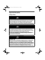
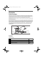
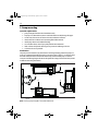
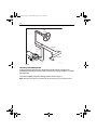
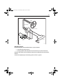
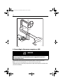
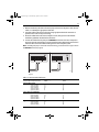
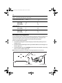
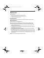
81178_5.book Page 1 Wednesday, April 24, 2013 6:42 PM
Hydraulic Pump
Installation Guide
Drives covered:
E12139
Type 0.5 Hydraulic Pump 12 V
M81120 Type 1 Hydraulic Pump 12 V
M81119 Type 1 Hydraulic Pump 24 V
M81121 Type 2 Hydraulic Pump 12 V
M81123 Type 2 Hydraulic Pump 24 V
M81122 Type 3 Hydraulic Pump 12 V
M81124 Type 3 Hydraulic Pump 24 V
Document number: 81178-5
April 2013
81178_5.book Page 2 Wednesday, April 24, 2013 6:42 PM
2
Important information
Safety notices
WARNING
Intended use
A properly installed and operated hydraulic pump as part of an autopilot
system is designed to be used only as a backup to a vessel’s existing
primary steering system. The autopilot system is NOT intended or
warranted to be used as a replacement for the primary steering system.
WARNING
Product installation
This equipment must be installed in accordance with the instructions
contained in this handbook. Failure to do so could result in poor product
performance, personal injury and/or damage to your boat.
Because correct performance of the boat’s steering is critical for safety,
we STRONGLY RECOMMEND that an Authorized Raymarine Service
Representative fits this product.
WARNING
Navigation aid
When this product is used within a navigation system, it is only an aid to
navigation. It’s accuracy can be affected by many factors, including
equipment failure or defects, environmental conditions and improper use
or handling. It is the user’s responsibility to exercise common prudence
and navigational judgements. This product should not be relied upon as a
substitute for such prudence and judgement. Always maintain a
permanent watch so that you can respond to situations as they develop.
81178_5.book Page 3 Wednesday, April 24, 2013 6:42 PM
3
WARNING
Ensure cleanliness
Absolute cleanliness is essential when working with hydraulic systems.
Even the smallest dirt particle could prevent the steering system check
valves from working correctly. Ensure that no dirt enters the system
during the installation, and that all hoses and fittings are cleaned before
making any connections.
EMC installation guidelines
Raymarine equipment and accessories conform to the appropriate Electromagnetic
Compatibility (EMC) regulations, to minimize electromagnetic interference between
equipment and minimize the effect such interference could have on the performance of your
system.
Correct installation is required to ensure that EMC performance is not compromised.
For optimum EMC performance we recommend that wherever possible:
• Raymarine equipment and cables connected to it are:
• At least 1 m (3ft) away from any equipment transmitting or cables carrying radio signals e.g. VHF radios, cables and antennas. In the case of SSB radios, the distance
should be increased to 7 ft (2 m).
• More than 2 m (7 ft) from the path of a radar beam. A radar beam can normally be
assumed to spread 20 degrees above and below the radiating element.
• The product is supplied from a separate battery from that used for engine start. This is
important to prevent erratic behavior and data loss which can occur if the engine start
does not have a separate battery.
• Raymarine specified cables are used.
• Cables are not cut or extended, unless doing so is detailed in the installation manual.
Note: Where constraints on the installation prevent any of the above recommendations, always ensure
the maximum possible separation between different items of electrical equipment, to provide the best
conditions for EMC performance throughout the installation.
Suppression ferrites
Figure 1 shows typical cable suppression ferrites used with Raymarine equipment. Always use
the ferrites supplied by Raymarine.
81178_5.book Page 4 Wednesday, April 24, 2013 6:42 PM
4
D3548-2
Figure 1
Connections to other equipment
If your Raymarine equipment is to be connected to other equipment using a cable not
supplied by Raymarine, a suppression ferrite MUST always be attached to the cable near to
the Raymarine unit.
Water ingress
Water ingress disclaimer
Although the waterproof rating capacity of this product meets the IP67 standard, water
intrusion and subsequent equipment failure may occur if the product is subjected to
commercial high-pressure washing. Raymarine will not warrant products subjected to highpressure washing.
Waste Electrical and Electronic Equipment Directive
The Waste Electrical and Electronic Equipment (WEEE) Directive requires the
recycling of waste electrical and electronic equipment. Whilst the WEEE Directive
does not apply to some of Raymarine’s products, we support its policy and ask you
to be aware of how to dispose of this product.
The crossed out wheelie bin symbol, illustrated above, and found on our products signifies
that this product should not be disposed of in general waste or landfill.
Please conact your local dealer, national distributor or Raymarine Technical Services for
information on product disposal.
Warranty
To register your Raymarine product ownership, please visit www.raymarine.com and
register online. It is important that you register your product to receive full warranty benefits.
Your unit package includes a bar code label indicating the serial number of the unit. You will
need this serial number when registering your product online. You should retain the label for
future reference.
81178_5.book Page 5 Wednesday, April 24, 2013 6:42 PM
5
IMO and SOLAS
The equipment described within this document is intended for use on leisure marine boats
and workboats not covered by International Maritime Organization (IMO) and Safety of Life
at Sea (SOLAS) Carriage Regulations.
Technical accuracy
To the best of our knowledge, the information in this handbook was correct when it went to
press. However, Raymarine cannot accept liability for any inaccuracies or omissions it may
contain. In addition, our policy of continuous product improvement may change
specifications without notice. As a result, Raymarine cannot accept liability for any
differences between the product and the handbook.
81178_5.book Page 6 Wednesday, April 24, 2013 6:42 PM
6
Introduction
Product description
The Raymarine hydraulic pump (also known as the Raymarine reversing hydraulic pump) is
intended to operate a vessel’s steering mechanism as part of a Raymarine autopilot system. It
is primarily designed for use on vessels with an existing hydraulic steering system.
Alternatively, you can use this pump on a vessel with mechanical steering in conjunction with
a secondary steering ram.
Raymarine pumps are driven by 12 or 24 V dc permanent magnet motors. The pumps include
pilot-operated check valves that prevent the pump being back driven by the manual steering
system or rudder load. The motors have an IP67 rating and can be removed from the pump
without allowing air into the hydraulic system or fluid to escape. The pumps also include
compatibility with balanced or unbalanced cylinders and can be used with pressurised
reservoir systems.
Optional reservoir port
Ram ports
Reservoir port
Gear pump
Motor
Check valve
Mounting foot
D5175-2
Figure 2
Contents
This guide contains:
1
Product specifications
page 7
2
Installation instructions
page 8
3
Maintenance information
page 21
81178_5.book Page 7 Wednesday, April 24, 2013 6:42 PM
7
Specifications
Pump specifications
Table 1-1: Pump specifications
Performance
(at nominal voltage)
Type 0.5
E12139 (12 V)
Ram compatibility
Ram capacity
(min-max)
Type 1 (T1)
M81120 (12 V)
M81119 (24 V)
Type 2 (T2)
M81121 (12 V)
M81123 (24 V)
Type 3 (T3)
M81122 (12 V)
M81124 (24 V)
230-350 cc
(14-21.4 in3)
350-500 cc
(21-30.5 in3)
single or double ended
50-110cc
(3.1-6.7 in3)
Maximum intermittent
pressure (at 12 V)
80-230 cc
(4.9-14.0 in3)
55 bar (800 psi)
Peak flow rate
(no load)
600 cc/min
(36.6 in3/min)
1000 cc/min
(61.0 in3/min)
2300 cc/min
(140.4 in3/min)
3100 cc/min
(189.2 in3/min)
Typical current at 12 V, 55
bar
9A
19 A
24 A
34 A
Typical current at 24 V, 55
bar
N/A
9A
11A
15.5 A
Other information
(applies to Types 0.5, 1, 2 and 3)
protected for use in engine compartments
CE approvals - conforms to:
2004/108/EC (EMC), EN60945:2002
94/25/EC (RCD), EN28846:1993 & EN ISO 10592:1995.
IEC 60529 IP67
Pump dimensions
All ports are 1/4 inch BSPP (parallel threaded)
89 mm (3.50 in)
A
4 holes for M6 (0.25 in) bolts
B
Figure 3
103 mm (4.05 in)
D5174-2
81178_5.book Page 8 Wednesday, April 24, 2013 6:42 PM
8
Table 1-2: Pump dimensions
Dimension
Type 0.5
E12139 (12 V)
Type 1 (T1)
M81120 (12 V)
Type 1 (T1)
M81119 (24 V)
Type 2 (T2)
M81121 (12 V)
M81123 (24 V)
Type 3 (T3)
M81122 (12 V)
M81124 (24 V)
A
58.4 mm
58.4 mm
58.4 mm
59.5 mm
61.4 mm
B
203 mm
199 mm
203 mm
204 mm
206 mm
Installation instructions
Parts required
To install this drive you will need:
• Parts supplied:
• hydraulic pump
• 1/4 in BSP bonded rubber / metal seals (x3)
• if required: 1/4 in BSP to 1/4 in NPT adaptors (x3)
• Additional parts:
• suitable hydraulic pipes, hydraulic fluid, T-pieces, and pipe fittings (see page 11)
• suitable securing bolts and lock nuts (see page 10)
• cable and electrical connectors for the drive motor (see page 16)
81178_5.book Page 9 Wednesday, April 24, 2013 6:42 PM
9
Installation steps
WARNING
Electrical safety
Make sure you have switched off the power supply before you start
installing this product.
Follow these steps to install your hydraulic pump:
1
page 3
Consult the EMC installation guidelines.
2
page 10
Mount the pump.
3
Connect to the hydraulic steering system.
page 11
4
Connect to the SPX course computer or Evolution ACU (Actuator Control
Unit).
page 16
5
Complete the post-installation checks.
page 19
81178_5.book Page 10 Wednesday, April 24, 2013 6:42 PM
10
2. Pump mounting
Location requirements
• pump is designed for below-deck installations only.
• fit pump to a substantial structure to avoid vibration that could damage the pipes.
• mount away from sources of heat and excessive vibration and fumes.
• do NOT mount in confined areas containing flammable materials.
• install pump above areas liable to flooding.
• on a suitable surface, clear of spray and possible water immersion.
• level or above the hydraulic steering ram to prevent air collecting in the ram.
• as close to the ram as possible.
Orientation
The pump can be mounted in any orientation. If mounting vertically, position the pump in a
motor-up orientation if possible. The pump has 2 reservoir ports (“R port”). In all cases, select
the R Port which best allows the hose to continuously rise to the helm pump or external
reservoir. The following diagram illustrates the preferred routing of the reservoir hose, based
on different mounting orientations:
R
R
R
R
D12808-1
Figure 4:
Note: Secure the pump using M6 (1/4 inch) bolts and lock nuts.
81178_5.book Page 11 Wednesday, April 24, 2013 6:42 PM
11
3. Hydraulic connections
WARNING
Pressurized systems
Before disconnecting any pipes on pressurized systems, you MUST release
the pressure at the reservoir by following the manufacturer’s
instructions.
CAUTION
Pump connection
Before you connect the autopilot pump to your hydraulic system we
strongly recommend that you consult the steering gear manufacturer.
CAUTION
Hydraulic systems
Absolute cleanliness is essential when working with hydraulic systems.
Even the smallest particle of dirt could prevent the steering system
check valves from working properly.
Connections overview
Optional reservoir port
Ram ports
Reservoir port
D12809-1
Figure 5
81178_5.book Page 12 Wednesday, April 24, 2013 6:42 PM
12
General guidelines
• All ports on the autopilot pump are 1/4 in BSPP parallel threaded. If you need to convert to
1
/4 in NPT, use the three BSPP to NPT adaptors (supplied). Use only bonded rubber / metal
washers to seal the fittings. Do NOT use tapered adapters, sealing compound, or PTFE
tape.
• The ram ports are the service line connections to the ram. The hydraulic hoses and connections must be of a suitable pressure rating. Refer to the Technical Specification in this document.
• The reservoir port is the reservoir or balance line and MUST be connected, through a continuous rise to the helm pump lowest connection or other external reservoir. To avoid
potential damage or steering failure, do NOT plug this reservoir port. The optional reservoir port on the top of the unit is an optional port to allow for the most appropriate fitting
of pipes, depending on the mounting orientation of the pump. The optional port is
accessed by removing the blanking plug.
• All pipes used to fit the pump should match, or exceed, the specification of the existing
steering system pipes. Contact the steering system manufacturer if you need more information.
• Use flexible pipe to connect the pump to the boat’s steering system - this avoids strain on
the pipes.
• Try to keep hydraulic fluid loss to a minimum when installing the pump. This will reduce
the time and effort required to bleed the system of trapped air after installation:
• non-pressurized systems: temporarily fit a non-venting plug to the helm reservoir vent
to minimize fluid loss
• pressurized systems:
• Follow the manufacturer’s instructions if you fit any T-pieces.
• The reservoir hose must be of a suitable pressure rating. Refer to the Technical Specification in this document.
• All hydraulic pipes should slope upwards towards the reservoir.
• A set of bleed valves near the steering ram, fitted at the highest point, will allow any
air to escape upwards.
CAUTION
PTFE tape
Do not use PTFE tape or a pipe sealing compound on hydraulic pipe
connections to ensure a leak-proof joint.
81178_5.book Page 13 Wednesday, April 24, 2013 6:42 PM
13
CAUTION
Hydraulic fluid
• Before running the pump for the first time, make sure the system contains sufficient
hydraulic fluid. You will damage the pump if you let it run when ‘dry’.
• Do NOT use “brake fluid”. Use only mineral-based good quality hydraulic fluid compatible with nitrile rubber hydraulic seals.
• For suitable hydraulic fluid, refer to the helm pump manufacturer’s recommendations
for compatibility. Also refer to the technical data provided in the technical specification
section of this document.
Check valves
For single-steering position boats:
• Consult the steering gear manufacturer to determine whether the helm pump is fitted
with reversing check valves:
• without check valves, the autopilot pump will drive the helm pump (sometimes
referred to as ‘motoring the wheel’) instead of moving the steering ram
• If the boat has a single helm pump system without check valves, you must incorporate a double pilot check valve (part number M81166).
• A double pilot check valve may also be necessary on long tubing runs - otherwise tubing expansion may cause poor autopilot performance.
Note: If the boat has two steering positions, it will already have check valves installed so the two
wheels can operate independently.
Hydraulic steering systems
There are three basic types of hydraulic steering systems:
• two line systems
• two line pressurized systems
• three line systems
On the following pages typical connection points are described for the autopilot pump on
each of these systems. For all of the systems you will need to connect a third hydraulic pipe
(as shown) between the autopilot pump and the helm pump or system reservoir.
Two line systems
Figure 6 shows a typical two line steering system. Hydraulic fluid flows into the ram in either
direction, depending on the direction the helm pump rotates. Connect the autopilot pump to
the steering system as shown in Figure 6.
81178_5.book Page 14 Wednesday, April 24, 2013 6:42 PM
14
Helm
pump
Ram pipes
Reservoir
pipe
Steering ram
Autopilot
pump
D5163-2
Figure 6
Two line pressurized systems
Two line pressurized systems have an external pressurized reservoir. This reduces the
possibility of introducing air into the system and reduces any steering ‘sponginess’ caused by
pipe expansion.
Connect the autopilot pump to the steering system as shown in Figure 7.
Note: Refer to the manufacturer’s instructions for de-pressurizing and re-pressurizing the system.
81178_5.book Page 15 Wednesday, April 24, 2013 6:42 PM
15
Helm
pump
Reservoir pipe
Pressurized reservoir
Ram pipes
Autopilot
pump
Steering ram
D5162-2
Figure 7
Three line systems
In a three line system, the hydraulic fluid flows in only one direction:
• out of the helm pump to the ram
• returning from the other side of the ram to the reservoir via a common return line
The system will include a check valve block to direct all returned fluid from the ram back to the
reservoir.
Connect the autopilot pump to the steering system as shown in Figure 8.
81178_5.book Page 16 Wednesday, April 24, 2013 6:42 PM
16
Helm
pump
Check valve
Reservoir
pipe
Ram pipes
Autopilot
pump
Steering ram
D5161-2
Figure 8
4. Connecting to the course computer or ACU
WARNING
Electrical safety
Make sure you have switched off the power supply before you start
installing this product.
The hydraulic pump has electrical connections for its motor: a red and a black cable.
Note: To meet current EMC legislation, you must NOT untwist the pump cables.
Follow these steps to connect the pump motor to an SPX course computer or Evolution ACU
(Actuator Control Unit):
81178_5.book Page 17 Wednesday, April 24, 2013 6:42 PM
17
1. Measure the distance of cable run from the pump to the course computer or ACU, then use
Table 1-3 to identify the appropriate cable sizes.
2. Join these cables to the ones on the pump using appropriate electrical connectors or
junction boxes at the correct power rating.
3. Route the cables back to the course computer or ACU, taking into account the EMC
installation guidelines described in this document.
4. Connect the cables from the pump to the MOTOR terminals on the course computer or
ACU (see Figure 9): at this stage you can connect either motor cable to either terminal. You
will check these connections after installing the rest of the autopilot system.
Note: If installing the pump on a boat with mechanical steering, you need to connect a bypass valve to
the CLUTCH terminals (see page 18).
A
POWER
GROUND
B
SOLENOID
A
POWER
SOLENOID
GROUND
B
MOTOR
D5171-2
Figure 9
Table 1-3: Recommended cable sizes
Cable length
(pump to course computer or ACU)
Cable gauge
(AWG)
Copper area
(mm2)
Type 0.5 drive (12 V)
up to 3 m (10 ft)
up to 5 m (16 ft)
up to 7 m (23 ft)
up to 10 m (32 ft)
up to 16 m (52 ft)
14
12
10
8
6
2.5
4
6
10
16
Type 1 drive (12 V and 24 V)
up to 3 m (10 ft)
up to 5 m (16 ft)
up to 7 m (23 ft)
up to 10 m (32 ft)
up to 16 m (52 ft)
14
12
10
8
6
2.5
4
6
10
16
Type 2 drive 12 V
up to 5 m (16 ft)
up to 7 m (23 ft)
up to 16 m (52 ft)
10
8
6
6
10
16
81178_5.book Page 18 Wednesday, April 24, 2013 6:42 PM
18
Table 1-3: Recommended cable sizes (Continued)
Cable length
(pump to course computer or ACU)
Cable gauge
(AWG)
Copper area
(mm2)
Type 2 drive 24 V
up to 3 m (10 ft)
up to 5 m (16 ft)
up to 10 m (32 ft)
up to 16 m (52 ft)
12
10
8
6
4
6
10
16
Type 3 drive 12 V
up to 5 m (16 ft)
up to 7 m (23 ft)
up to 16 m (52 ft)
8
6
4
10
16
25
Type 3 drive 24 V
up to 5 m (16 ft)
up to 7 m (23 ft)
up to 16 m (52 ft)
10
8
6
6
10
16
Mechanical steering systems
If you are fitting the pump to a boat with mechanical steering you will need to connect it to a
secondary steering ram, along with a solenoid-operated bypass valve. This bypass valve
allows you to switch between autopilot course control and manual steering.
To fit to a mechanical steering system:
• Use suitable hydraulic pipes to connect the pump to the secondary steering ram and a
suitable reservoir.
• Install the solenoid-operated bypass valve (part number: M81167) across these pipes (as
shown in Figure 10).
• Connect the bypass valve to the CLUTCH terminals on the course computer or ACU using
at least 1.5 mm2 (16 AWG) copper cable.
Note: Follow the manufacturer’s instructions for mounting the hydraulic ram and reservoir.
Secondary steering ram
Bypass valve
Manual steering system
Autopilot pump
connect to CLUTCH
on course computer or ACU
connect to MOTOR
on course computer or ACU
D5172-3
Figure 10
81178_5.book Page 19 Wednesday, April 24, 2013 6:42 PM
19
5. Post-installation check
WARNING
Steering systems
Keep clear of moving steering systems at all times. Protect moving parts
from access during normal use.
Check the following points after installing the pump:
1.
2.
3.
4.
5.
Is the pump installed in such a way that hose lengths are kept to a minimum?
Is the pump secured to a substantial structure on the boat?
Have you connected a reservoir pipe between the helm pump and autopilot pump?
Have you fitted check valves where appropriate?
Are the hydraulic pipes made of a suitable flexible material (i.e. rubber or nylon) with a
suitable pressure rating?
6. Are power cables correctly routed and securely connected to the course computer or
ACU?
You have now finished installing the pump. After installing the rest of the autopilot you must
bleed all air from the system (see below).
Note: When you have installed the entire autopilot system, you will also need to complete an autopilot
steering check. Refer to the control unit handbook for more details.
Bleeding the system
Bleeding the hydraulic system correctly is one of the most important steps when installing the
autopilot hydraulic pump. If there is any air in the system the steering will feel unresponsive,
particularly when you turn the wheel to hardover.
IMPORTANT: Any air in the hydraulic system will greatly reduce the performance of the
autopilot and the overall steering system.
Follow the helm pump manufacturer’s instructions to fill the hydraulic hoses so that the A, B
& R hoses do not contain trapped air or air bubbles. The hose connections to the pump may
need to be loosened to allow air to escape. The pump can now be run. Follow the set up
instructions for your autopilot control head. If the pump runs but the rudder does not move,
use the autopilot control head to initiate a course correction. This will start the pump.
Manually turn the helm wheel in the same direction as the course correction. This forces fluid
into the pump, displacing any residual air.
In addition to the manufacturer’s instructions for bleeding the steering system, follow these
steps to bleed the autopilot pump once you have installed and set up the rest of the autopilot
system:
81178_5.book Page 20 Wednesday, April 24, 2013 6:42 PM
20
1. With the system in auto mode, press the -10 button ten times:
• the autopilot pump will try to drive the rudder to port.
• counter this rudder movement by turning the helm to starboard to keep the rudder
stationary.
• you will be able to feel any air in the helm pump: any air in this side of the pump will
rise to the helm pump and exhaust into the reservoir.
• continue until all of the air is out of this side of the pump.
2. Clear any air on the other side of the pump:
• press the +10 button ten times.
• the autopilot will try to drive the rudder to starboard.
• counter the rudder movement by turning the helm to port.
• continue until all of the air is out of this side of the pump.
• Repeat in both directions until both sides of the help pump are totally free of air.
Note: Monitor the reservoir at all times and top up with the manufacturer’s recommended hydraulic
fluid as required.
CAUTION
Hydraulic system
After installation and bleeding, leave the system for 24 hours then check
for any air in the system or leaks at the joints and around the pump.
81178_5.book Page 21 Wednesday, April 24, 2013 6:42 PM
21
Maintenance
On a regular basis:
• check that all connections and mountings are secure.
• check pipes and cables for any signs of wear or damage.
• check pipes and joints for any leaks.
Pump maintenance
The pump contains no user-serviceable parts. Contact your dealer for more information.
Motor maintenance
The motor contains no user-serviceable parts.
However, for the purposes of replacement or coupling examination, the motor can be
removed from the pump head without fluid loss or air ingress into the hydraulic system:
1. Undo the two M6 socket head cap screws (5 mm AF allen key) and remove the motor,
coupling, and water seal ‘O’ ring.
2. If the coupling is worn or damaged it will need to be replaced. Lubricate the slots with a
small quantity of good quality grease.
3. If any hydraulic fluid is found in the coupling area, the pump shaft seal will need to be
replaced. Refer to your dealer for instructions.
4. Reassemble by replacing the ‘O’ ring. Engage the coupling between the motor and pump
shafts, ensuring that the motor locates correctly in the pump spigot. Using a low-strength
thread-locking compound, replace and tighten the two M6 socket head cap screws, using
13.5 Nm torque.
Note: Keep all parts clean during dismantling and reassembly.
81178_5.book Page 22 Wednesday, April 24, 2013 6:42 PM
22
Troubleshooting
Table 1-4: Possible problems and their solutions
Problem
Possible solutions
Motor does not run
• Check electrical connections.
• Check autopilot output.
• Check fuse / trip rating.
Motor runs, but no ram movement
•
•
•
•
•
Excessive noise
• Check for air in the hydraulic system.
• Check the motor for damage.
• Check the security of the mountings.
Check for air in the hydraulic system.
Check for incorrect hydraulic connections.
Check there is sufficient fluid in the system.
Check that the relief is set correctly, if fitted.
Check the drive coupling between the pump
and the motor.
• Check whether the pump has been dismantled and incorrectly reassembled.
EMC servicing and safety guidelines
•
•
•
•
•
Raymarine equipment should be serviced only by authorized Raymarine service technicians. They
will ensure that service procedures and replacement parts used will not affect performance. There
are no user serviceable parts in any Raymarine product.
Some products generate high voltages: never handle the cables/connectors when power is being
supplied to the equipment.
When powered up, all electrical equipment produces electromagnetic fields. These can cause adjacent pieces of electrical equipment to interact with one another, with a consequent adverse effect
on operation. In order to minimize these effects and enable you to get the best possible performance from your Raymarine equipment, guidelines are given in the installation instructions, to
enable you to ensure minimum interaction between different items of equipment, i.e. ensure optimum Electromagnetic Compatibility (EMC).
Always report EMC-related problems to your nearest Raymarine dealer. We use such information to
improve our quality standards.
In some installations, it may not be possible to prevent the equipment from being affected by external influences. In general this will not damage the equipment but it can lead to spurious resetting
action, or momentarily may result in faulty operation.
81178_5.book Page 23 Wednesday, April 24, 2013 6:42 PM
23
Product support
Raymarine products are supported by a worldwide network of distributors and Authorized
Service Representatives. If you encounter any difficulties with this product, please contact
either your national distributor, or your service representative, or the Raymarine Technical
Support Call Center.
Refer to the Raymarine website for contact details:
www.raymarine.com
81178_5.book Page 24 Wednesday, April 24, 2013 6:42 PM