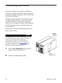
1
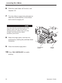
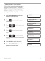
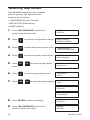
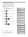
R t P/N 136578–001, Rev B US and CANADA Radio Interference Note This device complies with Part 15 of the FCC Rules. Operation is subject to the following two conditions: (1) this device may not cause harmful interference, and (2) this device must accept any interference received, including interference that may cause undesired operation. Properly shielded and grounded cables and connectors must be used in order to meet FCC emission limits. The manufacturer is not responsible for any radio or television interference caused by using other than recommended cables and connectors or by unauthorized changes or modifications to this equipment. Unauthorized changes or modifications could void the user’s authority to operate the equipment. The input/output (I/O) cable must be shielded for the printer to comply with FCC rules and regulations Part 15 governing the radiation limits for Class “A” equipment. This digital apparatus does not exceed the Class A limits for radio noise emissions from a digital apparatus set out in the radio interference regulations of the Canadian Department of Communications. Le présent appareil numérique n’émet pas de bruits radioélectriques dépassant les limites applicables aux appareils numériques de la Classe A prescrites dans le règlement sur le brouillage radioélectrique émis par le Ministère des Communications du Canada. WARNING This is a Class A product. In a domestic environment this product may cause radio interference in which case the user may be required to take adequate measures. Printronix, Inc. makes no representations or warranties of any kind regarding this material, including, but not limited to, implied warranties of merchantability and fitness for a particular purpose. Printronix, Inc. shall not be held responsible for errors contained herein or any omissions from this material or for any damages, whether direct, indirect, incidental or consequential, in connection with the furnishing, distribution, performance or use of this material. The information in this manual is subject to change without notice. This document contains proprietary information protected by copyright. No part of this document may be reproduced, copied, translated or incorporated in any other material in any form or by any means, whether manual, graphic, electronic, mechanical or otherwise, without the prior written consent of Printronix, Inc. All rights reserved. Trademarks Printronix is a registered trademark of Printronix, Inc. IGP is a registered trademark of Printronix, Inc. LinePrinter Plus is a trademark of Printronix, Inc. HP is a registered trademark of Hewlett–Packard Company. PCL is a trademark of Hewlett–Packard Company. Code V is a trademark of QMS, Inc. QMS is a registered trademark of Quality Micro Systems, Inc. IBM is a registered trademark of International Business Machines Corp. 17500 Cartwright Road, P.O. Box 19559 Irvine, California 92713 Telephone (714) 863–1900 FAX (714) 660–8682 Technical Support (714) 221–2686 COPYRIGHT 1997, PRINTRONIX, INC. This guide covers basic operating procedures for the Printronix. T3204 and T3304 label printers. Printronix wants you to feel comfortable and confident using the T3204 and T3304 label printers, and this guide. The guide has been designed to meet the needs of all users, from beginners to those experienced with thermal printers. All text and illustrations refer to both T3204 and T3304 printers except when noted. Follow the directions in this guide along with those in your Setup Guide in order to avoid injury to you and damage to the printer. Conventions Notes, Cautions, and Warnings Notes provide supplemental information that could affect printer operation or use. Cautions describe conditions that could damage the printer. Warnings describe conditions that could harm you as well as damage the equipment. Message Display These boxes show display messages as they appear on the printer. PAPER EMPTY BASIC OPERATING PROCEDURES Powering on the Printer . . . . . . . . . . . . . . . . . . . . . . . . . . . . . . . . . . . . . . . . . . . . . 1 Using the Primary Operator Panel . . . . . . . . . . . . . . . . . . . . . . . . . . . . . . . . . . . 1 Printing Modes . . . . . . . . . . . . . . . . . . . . . . . . . . . . . . . . . . . . . . . . . . . . . . . . . . . . 5 Loading Media . . . . . . . . . . . . . . . . . . . . . . . . . . . . . . . . . . . . . . . . . . . . . . . . . . . . 6 Unloading Media . . . . . . . . . . . . . . . . . . . . . . . . . . . . . . . . . . . . . . . . . . . . . . . . . 14 Installing the Ribbon . . . . . . . . . . . . . . . . . . . . . . . . . . . . . . . . . . . . . . . . . . . . . . 17 Removing the Ribbon . . . . . . . . . . . . . . . . . . . . . . . . . . . . . . . . . . . . . . . . . . . . . 20 INITIAL SETUP Selecting Print Mode . . . . . . . . . . . . . . . . . . . . . . . . . . . . . . . . . . . . . . . . . . . . . . 23 Selecting Gap Sensor . . . . . . . . . . . . . . . . . . . . . . . . . . . . . . . . . . . . . . . . . . . . . 24 Setting Print Intensity . . . . . . . . . . . . . . . . . . . . . . . . . . . . . . . . . . . . . . . . . . . . . 25 Selecting Media Handling . . . . . . . . . . . . . . . . . . . . . . . . . . . . . . . . . . . . . . . . . . 26 Selecting the Ribbon Saver . . . . . . . . . . . . . . . . . . . . . . . . . . . . . . . . . . . . . . . . 28 TROUBLESHOOTING Cleaning the Printer . . . . . . . . . . . . . . . . . . . . . . . . . . . . . . . . . . . . . . . . . . . . . . . 29 Fault Messages . . . . . . . . . . . . . . . . . . . . . . . . . . . . . . . . . . . . . . . . . . . . . . . . . . 31 Table of Contents i ii Before powering on the printer, make sure it is plugged into the appropriate power source. Refer to the “Select a Site” section in Chapter 2 of the Setup Guide for information on proper power sources. The power switch is located on the lower right–hand corner of the rear of the printer. It is marked for power OFF and | for power ON. For help with diagnosing printer problems, printer self–test routines are automatically run during the power–on cycle. Further diagnostic tests can be performed using the secondary operator panel functions. They are covered in detail in the Setup Guide. AC Power Switch AC Power Connector Fuse Holder Using the Primary Operator Panel Use the primary operator panel to perform routine operations. The panel contains three operator-accessible keys and three indicator lights, used to control and indicate printer status. The functions and meanings of some of the keys and indicators on the primary operator panel will change depending on the firmware installed. This manual describes printer operation with Printronix LP+, IGP/PGL or IGP/VGL emulation firmware installed. If your printer has Printronix IGP/FGL emulation firmware, please refer to the T3306 and T3308 Label Printers Operator’s Guide, p/n 136452–001. There is also a secondary operator panel, consisting of a message display and six keys. This panel is used to configure the printer and to run self–tests, via the configuration menus. Operator’s Guide Message Display Primary Control Panel Message Display Contrast Adjust Secondary Control Panel 1 using the primary operator panel Selections from the main menu will need to be changed when changes in the print mode, media size, options and various other configuration items are required for the printer. Instructions begin on page 23 of this guide. Refer to the “Configuring the Printer” chapter in the Setup Guide for complete instructions in how to access and use the secondary operator panel. The following pages describe the status indicator lights and keys comprising the primary operator panel, along with the related operating modes. Status Indicator Lights The three status indicator lights (LEDs) provide information about current printer operation, as follows: • POWER — Lit when the printer is powered on. • ON LINE/PAUSE — Lit when the printer is on line or blinking when the printer is off line or in a standby/fault state. ON LINE/ PAUSE RIBBON MEDIA POWER • RIBBON MEDIA — Lit when the printer sensors fail to detect label media or the presence of a ribbon. Keys Three primary operator panel keys provide for the basic, day-to-day control of the printer, as described on the following pages. 2 Operator’s Guide using the primary operator panel CANCEL Function Cancels all jobs, if pressed when the printer is off line and not in a fault state. Also clears faults and puts the printer in the off line mode. Action With the printer off line, cancel the current run of labels by pressing once. Also, if a fault condition persists, press once to clear fault. Result The printer will then cancel all jobs and clear all imaged and buffered data. Or, in the case of fault clearing, the printer will go off line without canceling jobs. CANCEL Pressing the CANCEL key has no effect when the printer is on line and running. FEED FEED Function Prints any labels that have been imaged and also the current label in progress. Action With the printer off line, press once to print labels. Result The printer will print any labels that have been imaged and also the current label in progress. If no label is being processed, a blank page will print. Operator’s Guide 3 using the primary operator panel ON LINE/PAUSE Function Temporarily stops the printing of labels and controls the on line/ off line status of the printer. Action ON LINE/ PAUSE To pause the printer, press once. The on line/pause indicator will blink. To place the printer in the on line mode, press once. The on line/ pause indicator will light. Result When the printer is paused, the print mechanism will stop when printing of the current label is completed. All data will be held in memory. When the printer is in the on line mode, the remaining labels in the batch will be printed. 4 Operator’s Guide The printer is capable of printing in either of two modes: • Direct Thermal only (T3204–20 and T3304–20) • Direct Thermal and Thermal Transfer (T3204–21 and T3304–21) The two modes have in common the application of heat to produce the printed image.They differ in the way the heat is applied. In thermal transfer printing, the individual dot elements of the printhead apply heat to a ribbon. The ink on the ribbon is a specially formulated material that melts onto the print media, bonding with the media to produce an image. Direct thermal printing does not use a ribbon. Instead, the printer applies heat directly to the print media, which reacts to the heat by turning black. All illustrations reflect the direct thermal and thermal transfer printer configuration (T3204–21 and T3304–21). This mode requires the use of a special direct thermal print media. It also requires that the ribbon be removed, if already installed. Using direct thermal print media with a ribbon installed will produce unacceptable print quality. The desired mode is selected through the printer menu system. The main menu is accessed via the secondary operator panel. Refer to the “Configuring the Printer” chapter in the Setup Guide for complete instructions in how to access and use the secondary operator panel. Operator’s Guide 5 Media Supply Window The printer accepts a wide range of media. It can be loaded with roll–fed, fan–folded, or die–cut continuous media of either thermal transfer or direct thermal type. Media width can range from 0.75 inches (19.1 mm) to 4.65 inches (118.1 mm). Media thickness can range from 0.0025 inches (0.0635 mm) to 0.01 inches (0.254 mm). Use the following procedures to load media of various kinds into the printer. Press ON LINE/PAUSE to place the printer in the off line mode. Media Supply Door Open the media supply door. 6 Rotate the printhead latch counterclockwise to unlatch, and raise the printhead to an upright position. Lower the hinge plate down. Slide the media guide to the outer edge, and rotate it to the down position. If you are loading fan–folded media, skip the next step and go on to step 6. Printhead Latch Media Guide Hinge Plate To load roll–fed media, continue as follows: Operator’s Guide Printers have been built with two types of standard media hubs: metal and plastic. From the diagrams below, follow the media loading instructions which match your printer. Do not use the media retainer if the media supply roll is wider than 4 inches. METAL HUB If you are using media with a 3” core, place the 3” media core adapters on the media hub assembly. Place the media supply roll on the media hub assembly. Slide the media retainer against the supply roll and tighten the thumb screw. PLASTIC HUB Place the 3” media supply roll on the media hub assembly. Slide the media retainer against the supply roll and tighten the thumb screw. Skip the next step and continue with step 7. Operator’s Guide 7 To load fan–folded media, proceed as follows: Place the media supply either behind or beneath the printer, as shown. Media Hub Assembly Make sure the media feeds freely from the container. Media Retainer Route the media through the rear media loading slot. Continue with step 7. Route the media over the guide plate, under the media sensor and over the platen roller (located beneath the printhead). Hinge Plate Media Edge Media Sensor Guide Adjust Fanfold Media Rotate the media guide up, and slide it to the edge of the media. Continue feeding the media under the printhead until the media exits the printhead assembly. Slide the media forward, until it extends beyond the printer front slot. Ensure that all media guides are adjusted to the width of stock being used. 8 Operator’s Guide 10 If the media you are loading is of the same width as the current media, skip the next step and go on to step 12. 11 If you are loading media that is of a different width from the current media, you may need to adjust print quality as follows: note The printer is aligned at the factory with 4–mil–thick label stock, whose width is the maximum width accepted by the printer. a. Raise the hinge plate, and lower the printhead by rotating the printhead latch clockwise to the latched position. Printhead Latch Media Guide Hinge Plate b. Press ON LINE/PAUSE to enable printing. c. Send a sample test print file from the host, or run the internal diagnostic test file. note It may be necessary to feed several labels before proper alignment of the media occurs. d. If the print quality is acceptable, go on to step 12. e. Otherwise, press ON LINE/PAUSE again to place the printer in the off line mode. note Although the head leveling knob can be adjusted during printing, it is recommended that this adjustment be done while the printer is paused. Operator’s Guide 9 Pull the head leveling knob outward, and rotate it one detent. Rotating the knob clockwise from position 1 will adjust the printer for media that is narrower than the maximum width accepted by the printer. When the head leveling knob is rotated clockwise from the detent position just before position 1 to position 1, the printhead will return to the maximum media width position. Head Leveling Knob Each of the 18 positions on the head leveling knob will raise or lower the printhead 0.003 inches (0.076 mm), giving a maximum adjustment range of 0.054 inches (1.37 mm). Return to step a and repeat until you obtain the desired print quality. If you do not intend to use the optional media rewind hub, skip the next step and go on to step 14. Use the rewind hub to print quantities of labels in single batches, for later use. The hub automatically rolls up the label media for convenient handling. It is also used with the automatic label peel-off dispenser option to roll up the media backing after labels have been peeled off. 10 Operator’s Guide 13 To use the media rewind hub, complete the following procedure. a. Lower the lower right-hand front panel. b. Remove the arc plate from its stored position, and install on the front of the printer. Route the media around the arc plate and to the media rewinder. c. Place the clasp over the end of the media, and rotate the media rewinder a few turns. Rotate the media guide up, and slide it to the media edge. d. Lift and snap the lower right-hand front panel closed. Continue with step 14. 14 Raise the hinge plate, and lower the printhead by rotating the printhead latch clockwise to the latched position. 15 Close the media supply door. 16 Press ON LINE/PAUSE to enable printing. note It may be necessary to feed several labels before proper alignment of the media occurs. Operator’s Guide 11 The peel-and-present option allows for on-demand label dispensing. Although the peel-and-present mechanism is included with every printer, the label present sensor and internal rewind options are required to use this feature. To use the optional peel-and-present, follow the instructions outlined below. Turn off the printer, and open the side access cover. Rotate the printhead latch counterclockwise to raise the printhead. Lower the hinge plate and the lower front panel. Using a Philips screwdriver, remove the tear bar, invert it (flip it over), and reinstall it. Place the media supply roll on the media hub assembly. Slide the media retainer against the supply roll, and tighten the thumbscrew. 12 Route the media over the guide plate, through the media sensor, and over the platen roller (located beneath the printhead). Operator’s Guide g. Route the media liner (backing) around the tear bar to the media rewinder. h. Place the clasp over the end of the media, and rotate the media rewinder a few turns. i. Rotate the media guide up, and slide it to the media’s edge. j. Lift and snap the lower right front panel closed. k. Raise the hinge plate, and latch the printhead by rotating the printhead latch clockwise to the latched position. l. Close the side cover. note It is possible to use the present sensor only (without inverting the tear bar) to provide on-demand label printing in the tear-off mode. To operate in this mode, media should be routed as shown in step f, and the Label Present menu selection should be enabled. Operator’s Guide 13 Media Supply Window Use the following procedure to unload media from the printer. Press ON LINE/PAUSE to place the printer in the off line mode. Open the media supply door. Rotate the printhead latch counterclockwise to unlatch, and raise the printhead to an upright position. Media Supply Door Lower the hinge plate down. Slide the media guide to the outer edge, and rotate it to the down position. Cut the media either before or after the front slot, depending on whether or not the rewind hub is being used. If the media rewind hub was being used, you may choose to continue winding the media onto the hub or to roll it back onto the supply roll (media hub). Printhead Latch Media Guide Hinge Plate If the installed media is fan–folded, skip the next step and go on to step 7. Otherwise, continue with step 6. 14 Operator’s Guide To remove roll–fed media, proceed as follows: 3–Inch Core Adaptors Media Hub Assembly Roll the media onto the media hub or onto the rewind hub, as appropriate. If you have rolled the media onto the media hub, slide the roll of media off the hub. If you have rolled the media onto the rewind hub, lower the lower right-hand front panel. Thumbscrews Media Supply Roll Media Hub Assembly Media Retainer Unroll the media from the hub, and remove the clasp Lift and snap the lower right-hand front panel closed. Rewind Hub To remove fan–folded media, proceed as follows: If the rewind hub was not being used, simply pull the media through the loading slot and out of the printer. Go on to step 8. If the rewind hub was being used, finish rolling the media onto the hub. Operator’s Guide 15 Lower the lower right-hand front panel. Unroll the media from the hub, and remove the clasp. Lift and snap the lower right-hand front panel closed. Right-Hand Front Panel Rewind Hub Continue with step 8. Raise the hinge plate, and lower the printhead by rotating the printhead latch clockwise to the latched position. Close the media supply door. Printhead Latch 16 Hinge Plate Operator’s Guide Media Supply Window As noted previously, when printing in thermal transfer mode, the printer requires a ribbon. Use the following procedure to install a new ribbon. The thermal transfer mode is selected through the printer menu system. The main menu is accessed via the secondary operator panel. Refer to the “Configuring the Printer” chapter in the Setup Guide for complete instructions in how to access and use the secondary operator panel. Media Supply Door Press ON LINE/PAUSE to place the printer in the off line mode. Open the media supply door. Rotate the printhead latch counterclockwise to unlatch, and raise the printhead. Lower the hinge plate. Place the new ribbon supply roll on the supply hub. Printhead Latch Operator’s Guide Hinge Plate 17 Ribbon Supply Roll Supply Hub Take-Up Hub J-Hook Make sure the ribbon roll is pushed up against the hub flange. Route the ribbon to the take-up hub, as shown. 18 While holding the ribbon take-up hub, rotate the J-hook clockwise to unlatch it. Operator’s Guide Raise the J-hook upward, and place the end of the ribbon over the take-up hub. Slide the J-hook back into place, as shown. While holding the ribbon take-up hub, rotate the J-hook counterclockwise to latch. Turn the take-up hub until all the ribbon slack is removed. Raise the hinge plate, and lock the printhead by rotating the printhead latch clockwise. Printhead Latch Hinge Plate Close the media supply door. Press ON LINE/PAUSE to enable printing. J-Hook Take-Up Hub Ribbon Operator’s Guide 19 Generally, ribbons are used to completion and then replaced. Removal of the old ribbon is simply a matter of pulling it off the take–up hub and discarding it. However, there may be times when the use of direct thermal media is required and an installed ribbon has not been completely used up. (As noted previously, when printing in direct thermal mode, the printer does not use a ribbon.) In this case, use the following procedure to remove the ribbon. Media Supply Window The direct thermal mode is selected through the printer menu system. The main menu is accessed via the secondary operator panel. Refer to the “Configuring the Printer” chapter in the Setup Guide for complete instructions in how to access and use the secondary operator panel. Press ON LINE/PAUSE to place the printer in the off line mode. 20 Open the media supply door. Media Supply Door Operator’s Guide Ribbon Supply Roll Supply Hub Take-Up Hub J-Hook Printhead CUT Cut the ribbon anywhere between the take-up hub and the printhead. Rotate the printhead latch counterclockwise to raise the printhead, and then lower the hinge plate. While holding the ribbon take-up hub, rotate the J-hook clockwise to unlatch it. Operator’s Guide 21 Slide the used ribbon off the hub, and dispose of it. Turn the ribbon supply hub clockwise to draw the unused portion of the ribbon back onto the supply roll. You may leave the unused portion of the ribbon in place until the next thermal transfer print job, at which time you may reinstall it by following the ribbon installation procedure. 22 Raise the hinge plate, and lock the printhead by rotating the printhead latch clockwise. Close the media supply door. Printhead Latch Hinge Plate Press ON LINE/PAUSE to enable printing. Operator’s Guide PRINT MODE selects the printing mode of the printer. Selecting DIRECT THERMAL MODE activates direct thermal printing mode (ribbon must not be installed). Selecting THERMAL XFER activates thermal transfer printing mode (ribbon required). Press ON LINE/PAUSE to place the printer in the off line mode. Press twice to enter the paper OFFLINE IGP/PGL PAPER CONTROL Page Width control menu. Press until the print mode PAPER CONTROL Print Mode menu is displayed. Print Mode Thermal Xfer * Press to enter the print mode Print Mode Thermal Xfer * menu. Press to select between thermal transfer and direct thermal print methods. Print Mode Direct Thermal Print Mode * Direct Thermal Press ENTER to select the option. Press ON LINE/PAUSE to place the printer in the on line mode. Operator’s Guide ONLINE IGP/PGL 23 Selecting Gap Sensor GAP SENSOR selects the type of media used for printing. The options for this selection are as follows: • TRANSMISSIVE (see–through) • REFLECTIVE (black stripe) • NONE (default) Press ON LINE/PAUSE to place the printer in the off line mode. Press to enter the configuration menus. Press to reach the printer control menu. Press to enter the printer control menu. Press to reach the gap sensor menu. Press Press to enter the gap sensor menu. to view the desired setting. OFFLINE IGP/PGL USER CONFIG PAPER CONTROL USER CONFIG PRINTER CONTROL PRINTER CONTROL Media Handling PRINTER CONTROL Gap Sensor Gap Sensor None * Gap Sensor None * Gap Sensor Reflective Gap Sensor Transmissive 24 Press ENTER to select the setting. Gap Sensor Reflective * Press ON LINE/PAUSE to place the printer in the on line mode. ONLINE IGP/PGL Operator’s Guide The PRINT INTENSITY adjustment is used to balance a new printhead, so that it prints at the same level of darkness as did the previous head. You can specify intensity values from –10 through +10. The factory default setting is 0. Press ON LINE/PAUSE to place the printer in the off line mode. Press to enter the configuration OFFLINE IGP/PGL USER CONFIG PAPER CONTROL menus. Press to reach the printer control USER CONFIG PRINTER CONTROL menu. Press to enter the printer control PRINTER CONTROL Media Handling menu. Press to reach the print intensity menu. Press to enter the print intensity menu. Press to select the desired value. PRINTER CONTROL Print Intensity Print Intensity 0* Print Intensity –10 Print Intensity 0* Print Intensity 10 Press ENTER to select the setting. Press ON LINE/PAUSE to place the printer in the on line mode. Operator’s Guide Print Intensity –3 ONLINE IGP/PGL 25 The options for this selection are as follows: • SELF STRIP – selects the self strip option. When the label present sensor is installed and enabled, the printer can be configured for “one up” printing. • CUTTER selects the cutter mechanism option. The cutter must be installed to use this option. • TEAR OFF –selects the tear off option. • CONTINUOUS – selects the continuous feed option. Press ON LINE/PAUSE to place the printer in the off line mode. Press to enter the configuration OFFLINE IGP/PGL USER CONFIG PAPER CONTROL menus. Press to reach the printer control USER CONFIG PRINTER CONTROL menu. Press to enter the printer control PRINTER CONTROL Media Handling menu. 26 Operator’s Guide Press to enter the media handling Media Handling Continuous * menu. Press to view the desired Media Handling Continuous option. Media Handling Tear Off Media Handling Cutter Media Handling Self Strip Press ENTER to select the desired option. Media Handling Self Strip * Press ON LINE/PAUSE to place the printer in the on line mode. ONLINE IGP/PGL Operator’s Guide 27 Selecting the Ribbon Saver RIBBON SAVER selects the ribbon saver option, if the ribbon saver is installed. Press ON LINE/PAUSE to place the printer in the off line mode. Press to enter the configuration menus. Press to reach the printer control menu. Press OFFLINE IGP/PGL USER CONFIG PAPER CONTROL USER CONFIG PRINTER CONTROL to enter the printer control PRINTER CONTROL Media Handling to reach the ribbon PRINTER CONTROL Ribbon Saver menu. Press saver menu. Press to enter the ribbon saver Ribbon Saver Disable * menu. Press to view the desired Ribbon Saver Disable * option. Ribbon Saver Enable 28 Press ENTER to select the option. Ribbon Saver Enable * Press ON LINE/PAUSE to place the printer in the on line mode. ONLINE IGP/PGL Operator’s Guide Keeping the printer clean will help ensure efficient operation and good print quality. warning Media Supply Window Disconnect the AC power cord before cleaning the printer. Cleaning the Outside of the Cabinet Clean the outside of the cabinet with a soft, lint–free cloth and mild detergent (dishwashing liquid works well). Do not use abrasive powders or chemical solvents. Clean the window with plain water or a mild window cleaner. caution Media Supply Door Always apply the cleaning solution to the cloth; never pour cleaning solution directly onto the printer. Cleaning Inside the Cabinet Over time, it is normal for dust, particles of paper, and ink to accumulate inside the printer. Paper dust and ink build–up must be removed periodically to avoid degraded print quality. To clean the interior of the printer, perform the following steps. caution To avoid damage to the printer, be extremely careful when vacuuming and dusting around the printhead and surrounding areas. 1 2 3 Power–off the printer and unplug the power cord. Unload the media supply (page 14). Remove the ribbon, if installed (page 20). Operator’s Guide 29 Using a soft–bristled, non–metallic brush, remove dust particles from the media path, ribbon guides and ribbon path. Cotton Swab Brush and vacuum accumulated dust or residue, especially in the printhead areas. Using a cloth dampened with anhydrous alcohol, clean the ribbon guides, rollers and mechanical assemblies. The printhead will require cleaning after extended normal operation. Regular cleaning will ensure the highest print quality. Clean the printhead using a clean cotton swab and anhydrous alcohol. Printhead Element Printhead Printhead Latch Hinge Plate When the cutter or tear bar become dirty with gummed media backing, clean the area using a clean, lint–free cloth and anhydrous alcohol. Wipe the cabinet interior with a clean, lint–free cloth damp (not wet) with water and mild detergent, or spray the surfaces lightly with window cleaning solution. Dry the interior with a dry, clean, lint–free cloth. Reload the media (page 6) and ribbon (page 17). 30 Operator’s Guide If a printer fault occurs, a specific message appears in the message display. When this happens, correct the fault immediately. You can correct most faults by performing a simple procedure, such as clearing a media jam or reloading media or ribbon. For more serious faults, however, call an authorized Printronix service representative. PROM Fault PROM FAULT Power–up initialization test detected a PROM failure. Contact your authorized service representative. RAM Fault RAM FAULT Power up initialization test detected a RAM failure. Contact your authorized service representative. RTC RAM Fault RTC RAM FAULT PRINTHEAD CONTROL FAIL A–D CONVERTER FAIL Operator’s Guide The RTC non–volatile RAM failed the checksum test. Contact your authorized service representative. Printhead Control Fail Thermal printhead control circuit failed. Contact your authorized service representative. A–D Converter Fail Analog–to–digital converter failed. Contact your authorized service representative. 31 Paper Jam PAPER JAM Possible causes: • Improper media. • Actual label length greater than programmed label length. Paper Empty PAPER EMPTY Printer is out of media stock. Media Fault MEDIA FAULT The ribbon system detected a fault. Possible causes: • Out of ribbon. • Ribbon motion was stopped. • Obstructions in the media movement. • Paper motion stopped. Cutter Fault CUTTER FAULT The cutter operation failed. Possible causes: • Cutter is jammed. • Defective cutter hardware. Ribbon Saver Fault RIBBON SAVER FAULT Ribbon saver operation failed. Possible causes: • Obstruction in ribbon area. • Defective ribbon saver hardware. PRINTHEAD TEST FAIL 32 Printhead Test Fail The printer has detected a failure in one or more printhead dots. Operator’s Guide "% " & $ & $ & #%% % " " ! & !#" !" " !#" #!" ! & $!" # !"" %!" " http://www.printronix.com 136578–001B