1
Digital LA400 MultiPrinter
User Guide
Digital Equipment Corporation
Maynard, Massachusetts
First Printing, May 1996
The contents of this guide may be revised without prior notice and without obligation to
incorporate changes and improvements into units already shipped.
Every effort has been made to ensure that information included here is complete and
accurate at the time of publication: however, Digital Equipment Corporation cannot be
held responsible for errors and omissions.
No part of this guide may be reproduced or translated, stored in a database or retrieval
system, or transmitted, in any form or by any means, electronic, mechanical,
photocopying, recording, or otherwise, without the prior written permission of Digital
Equipment Corporation 1996. All rights reserved.
The following are trademarks of Digital Equipment Corporation: LA400 MultiPrinter and
the Digital logo.
Centronics is a trademark of Centronics Data Computer Corporation. IBM PC, IBM
Proprinter X24E and IBM Proprinter XL24E are trademarks of International Business
Machines Corporation. ESC/P2 is a trademark of Seiko Epson Corporation. Microsoft is a
registered trademark and MS-DOS, Windows and Microsoft BASIC are trademarks of
Microsoft Corporation.
Other products names mentioned in this guide may also be trademarks of their respective
companies.
As an Energy Star TM Partner. Digital Equipment Corporation has determined that this product
meets the Energy Star TM guidelines for energy efficiency.
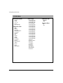
Table of Contents
Preface
About this Guide............................................................................................................x
Notes, Cautions and Warnings.......................................................................................x
1. What Your New Printer Offers
Paper Handling Flexibility .........................................................................................1.1
Connectivity................................................................................................................1.2
Robustness and Reliability .........................................................................................1.2
Printing on Several Types of Paper ............................................................................1.2
Numerous Printing Capabilities .................................................................................1.2
Ease of Use .................................................................................................................1.3
Low Cost Ownership..................................................................................................1.3
2. Getting to Know Your Printer
Parts of the Printer ......................................................................................................2.3
Front and Left View ..............................................................................................2.3
Rear and Right View .............................................................................................2.3
Internal View.........................................................................................................2.3
The Ribbon Cartridge .................................................................................................2.4
The Black Ribbon Cartridge.................................................................................2.4
The Push Tractor Unit ................................................................................................2.5
The Push Tractor Unit in Front Position ..............................................................2.6
The Push Tractor Unit in Rear Position................................................................2.7
The Operator Panel.....................................................................................................2.8
The Indicators .......................................................................................................2.8
The State Indicators ........................................................................................2.9
The Paper Path Indicators .............................................................................2.10
The Buttons.........................................................................................................2.11
The Operating States.....................................................................................2.12
The Operating Modes ...................................................................................2.12
The Function of the Buttons in Normal Mode .............................................2.14
The Function of the Buttons in Set-Up Mode ..............................................2.16
The Functions of the Buttons in Top of Form Mode ....................................2.18
The Display.........................................................................................................2.19
The Basic Screen...........................................................................................2.19
The Font/Pitch Screen...................................................................................2.20
The Different Types of Interactive Messages ...............................................2.22
iii
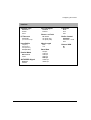
3. Handling Different Types of Paper
Paper Types.................................................................................................................3.1
Tips on Paper Quality ...........................................................................................3.1
Multipart Paper ...............................................................................................3.2
Envelopes ........................................................................................................3.2
The Paper Paths ..........................................................................................................3.2
Push-Front.......................................................................................................3.3
Push-Rear ........................................................................................................3.3
Manual ............................................................................................................3.4
Pull ..................................................................................................................3.4
Push+Pull ........................................................................................................3.4
How to Select a Paper Path...................................................................................3.5
Using Set-Up Mode ........................................................................................3.5
Using the Operator Panel ................................................................................3.6
Tips on Selecting the Proper Paper Path...............................................................3.6
Continuous Form ............................................................................................3.6
Cut Sheets .......................................................................................................3.7
Envelopes ........................................................................................................3.8
Adhesive Labels ..............................................................................................3.8
Handling Continuous Form ........................................................................................3.9
Handling Continuous Forms using the Push Tractorin Front Position ..............3.10
Mounting the Push Tractor Unit in Front Position ......................................3.10
Loading the Paper .........................................................................................3.13
Removing the Push tractor Unit from Front Position ........................................3.19
Handling Continuous Forms using the Push Tractor in Rear Position ..............3.21
Mounting the Push Tractor in Rear Position ................................................3.21
Loading the Paper .........................................................................................3.24
Removing the Push Tractor Unit from Rear Position...................................3.30
Parking the Paper......................................................................................................3.32
Unsuccessful Paper Parking..........................................................................3.32
Resetting Paper Position.....................................................................................3.32
Printing on Cut Sheets ..............................................................................................3.33
Loading Cut Sheets.............................................................................................3.33
Ejecting Cut Sheets.............................................................................................3.36
Printing on Adhesive Labels.....................................................................................3.37
Moving the Paper .....................................................................................................3.38
Viewing the Last Printed Line ............................................................................3.39
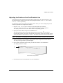
Advancing the Paper for Tearing-off ..................................................................3.40
iv
4. Operating Your Printer
Using Macros ............................................................................................................. 4.1
About Macros....................................................................................................... 4.1
Switching between Macros .................................................................................. 4.2
Selecting Print Features ............................................................................................. 4.3
Selecting the Font................................................................................................. 4.4
Selecting the Pitch .......................................................................................... 4.5
Holding a Print Task................................................................................................... 4.5
Reducing the Print Noise Level ................................................................................. 4.6
Recovering from a Fault State ................................................................................... 4.6
Recovering from a Paper out Fault ...................................................................... 4.6
Recovering from other Faults............................................................................... 4.6
5. Printing
Print Area Definition.................................................................................................. 5.1
Print Area Definition ............................................................................................ 5.2
Printing on Multipart Form........................................................................................ 5.4
Adapting to Paper Thickness ............................................................................... 5.4
Hints on Printer Settings for Paper Thickness ............................................... 5.5
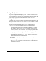
Managing Blank Pages .............................................................................................. 5.5
Printing on Pre-printed Forms ................................................................................... 5.6
Adjusting theTop of Form from the Operator Panel ............................................ 5.6
Quickly Switching between Two Paper Types........................................................... 5.7
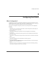
6. Configuring Your Printer
What is Configuration? .............................................................................................. 6.1
The Configuration Structure ...................................................................................... 6.2
Display Graphic Conventions .............................................................................. 6.3
The Different Types of Selectable Values ............................................................ 6.3
Configuration Quick Reference ........................................................................... 6.4
How to Configure your Printer ................................................................................ 6.12
Reaching, Selecting, Saving a Configuration Value .......................................... 6.12
Reaching a Configuration Item .................................................................... 6.12
Selecting a Configuration Value ................................................................... 6.12
Saving the new Configuration ...................................................................... 6.12
Example Configuring ......................................................................................... 6.13
Printing the Printer Configuration...................................................................... 6.14
Tips for Configuring........................................................................................... 6.14
v
How to Manage your Configuration ........................................................................6.16
Saving a Configuration .......................................................................................6.16
Restoring a Macro...............................................................................................6.16
Restoring all Macros...........................................................................................6.16
Recalling the Factory Configuration ..................................................................6.16
Setting the Printer Installation..................................................................................6.17
LCD Language....................................................................................................6.17
Error Buzzer........................................................................................................6.17
Paper Path at Power-On ......................................................................................6.17
Setting the Communication Interface.......................................................................6.18
Interface Type .....................................................................................................6.18
Interface Time-out ..............................................................................................6.18
Input Buffer Size.................................................................................................6.18
Setting the Parallel Interface...............................................................................6.19
Parallel Mode ................................................................................................6.19
AUTOFEED Signal ......................................................................................6.19
SELECT-IN Signal .......................................................................................6.19
Setting the Serial Interface..................................................................................6.20
Disconnection on Fault .................................................................................6.20
Word Length..................................................................................................6.20
Baud Rate ......................................................................................................6.20
Parity Bit .......................................................................................................6.21
Buffer Control ...............................................................................................6.21
Robust XON..................................................................................................6.21
Setting the User Access Authorization .....................................................................6.22
7. Customizing Macros
How to Customize a Macro........................................................................................ 7.1
Selecting the Protocol................................................................................................. 7.1
Setting the Publishing Style ....................................................................................... 7.2
Font ....................................................................................................................... 7.2
Vertical Pitch ........................................................................................................ 7.3
Setting the Page Layout.............................................................................................. 7.3
Form Length ......................................................................................................... 7.3
Left Margin ........................................................................................................... 7.4
Form Width ........................................................................................................... 7.4
Top Margin............................................................................................................ 7.4
Bottom Margin...................................................................................................... 7.4
Top of Form .......................................................................................................... 7.5
Selecting the Paper Path ............................................................................................. 7.5
Setting the Printing Modes......................................................................................... 7.6
vi
Print Direction ......................................................................................................7.6
Line Mode.............................................................................................................7.6
Blank Pages...........................................................................................................7.7
Print Impact...........................................................................................................7.7
Print Gap ...............................................................................................................7.8
How to Adjust the Print Gap Manually ..........................................................7.8
Automatic Gap Offset.........................................................................................7.10
Perforation Anti-jam ...........................................................................................7.10
Setting the Tear/View Mode .....................................................................................7.11
Paper Movements According to Tear/View Mode..............................................7.11
Automatic Advance Setting ..........................................................................7.12
Manual Advance Setting ...............................................................................7.12
No Tear/Reverse Setting ...............................................................................7.12
Paper Position Definition....................................................................................7.13
Setting the DEC Mode .............................................................................................7.15
Horizontal Pitch ..................................................................................................7.15
G0 Character Set.................................................................................................7.16
User Preference Character Set ............................................................................7.17
Printer ID ............................................................................................................7.17
Wrap or Truncate ................................................................................................7.18
Disconnection on EOT........................................................................................7.18
Initial Report .......................................................................................................7.19
Automatic ANSWERBACK...............................................................................7.19
ANSWERBACK on ENQ ..................................................................................7.19
Configuring the IBM Mode......................................................................................7.20
Horizontal Pitch ..................................................................................................7.20
IBM Character Set .............................................................................................7.20
Code Page ...........................................................................................................7.21
IBM Double Height ............................................................................................7.22
IBM AGM...........................................................................................................7.22
Horizontal Pitch on COMPRESS.......................................................................7.22
Slashed Zero .......................................................................................................7.22
Setting the EPSON Mode.........................................................................................7.22
Horizontal Pitch ..................................................................................................7.23
National Character-Set........................................................................................7.23
Code Page ...........................................................................................................7.24
EPSON Character Set .........................................................................................7.25
Slashed Zero .......................................................................................................7.25
vii
8. Testing Your Printer
Printing the Self-Test ................................................................................................. 8.2
Hex Dump Printing .................................................................................................... 8.3
Initializing the Set-Up Card ....................................................................................... 8.3
9. Adjusting Your Printer
How to Adjust your Printer ........................................................................................ 9.1
Adjusting the Bidirectional Alignment...................................................................... 9.2
Adjusting the Position of the First Printable Line ..................................................... 9.3
Adjusting the Tear-off Position.................................................................................. 9.4
10. Maintenance
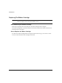
Cleaning The Printer ................................................................................................ 10.1
Cleaning and Vacuuming the Printer.................................................................. 10.1
When Cleaning the Printer ........................................................................... 10.1
How to Clean the Printer .............................................................................. 10.1
Replacing The Ribbon Cartridge ............................................................................. 10.2
When Replacing the Ribbon Cartridge .............................................................. 10.2
How to Replace the Ribbon Cartridge ............................................................... 10.2
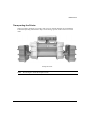
Transporting the Printer ........................................................................................... 10.3
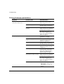
11. Troubleshooting
Installation Problems and Solutions ........................................................................ 11.1
Printing Problems and Solutions ............................................................................. 11.2
Paper Handling Problems and Solutions ................................................................. 11.5
Printer Failure........................................................................................................... 11.5
Hex-Dump Mode ..................................................................................................... 11.6
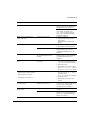
A. Supplies and Options
Supplies ..................................................................................................................... A.1
Options ...................................................................................................................... A.1
Push Tractor Unit ................................................................................................ A.1
Pull Tractor Unit.................................................................................................. A.1
What is the Pull Tractor Unit for ? ................................................................ A.1
Hints on Selecting the Proper Paper Path ........................................................... A.2
Mounting the Pull Tractor Unit ..................................................................... A.3
Loading Continuous Forms on the Pull Tractor Unit.................................... A.8
Set-Up Card....................................................................................................... A.12
What is the Set-Up Card for ? ..................................................................... A.12
How to Initialize the Set-Up Card............................................................... A.12
Copying your Configuration to the Set-Up Card ........................................ A.13
viii
Copying your Configuration from the Set-Up Card....................................A.14
Preparing for Color Printing..............................................................................A.15
Preparing the Color Ribbon Cartridge.........................................................A.15
Mounting the Color Mechanism..................................................................A.16
Installing the Color Ribbon Cartridge .........................................................A.19
Removing the Color Cartridge.....................................................................A.23
Supplies and Options Order Numbers ...................................................................A.24
Supplies..............................................................................................................A.24
Options...............................................................................................................A.24
Documentation...................................................................................................A.24
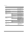
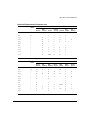
B. Technical Characteristics
Technical Specifications ............................................................................................ B.1
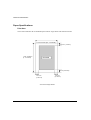
Paper Specifications .................................................................................................. B.4
Print Area ............................................................................................................. B.4
Paper Thickness ................................................................................................... B.6
C. LCD Display Messages
Simple messages........................................................................................................ C.1
User Instructions.................................................................................................. C.1
Status Messages ................................................................................................... C.2
Operating Messages............................................................................................. C.2
Rolling messages ....................................................................................................... C.3
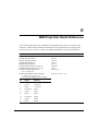
D. DEC PPL2 Quick Reference
Barcode Printing......................................................................................................D.12
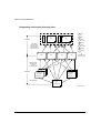
E. IBM Proprinter Quick Reference
F. EPSON ESC/P2 Quick Reference
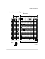
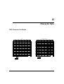
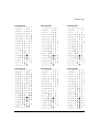
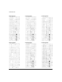
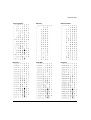
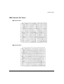
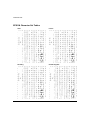
G. Character Sets
DEC Character Set Tables ......................................................................................... G.1
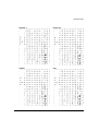
Generic Character Set Tables .................................................................................... G.6
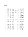
IBM Character Set Tables........................................................................................G.11
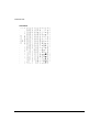
EPSON Character Set Tables ..................................................................................G.12
H. Retrieving Access to Configuration
ix
Preface
About this User Guide
Thank you for buying the Digital LA400 Multiprinter. You can expect years of reliable
service with very little maintenance. This guide explains how you can use your printer to
full advantage. It is written for both new and experienced users.
This guide consists of two parts: Setting Up Your Printer and User Guide. The former
describes how to install and set up your printer. This part is easily identifiable, as each
page has a gray border. The latter part describes how to use your printer and printer
options, how to keep the printer in good working condition, and what to do should
something go wrong. Detailed procedures are provided for first-time users. Experienced
users can skip some of the details, using the table of contents and chapter introductions to
locate specific information.
This part has several appendixes and an index. Appendix A lists supplies and options
available form your dealer or authorized representative of Digital Equipment Corporation.
Notes, Cautions and Warnings
The text contains three different types of annotation which should always be read.
Note:
x
This NOTE annotation provides you additional information, or indicates where
you can find it.
Caution:
This CAUTION annotation should catch your attention, advising you of a
particular situatio/problem which may occur/be avoided as a result of a
certain sequence of operations. It may also contain a reminder to execute a
particular operation.
Warning:
This WARNING annotation indicates a specific procedure which must be
strictly observed. Failure to comply with the instructions given may result in
injury to the operator and/or damage to the printer.
1
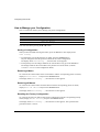
What Your New Printer Offers
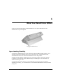
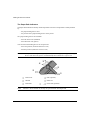
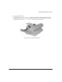
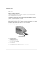
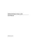
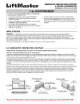
Thank you for choosing a Digital LA400 MultiPrinter. This chapter describes the main
characteristics of your new printer.
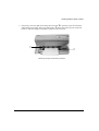
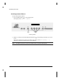
d400-c02
The Digital LA400 MultiPrinter
Paper Handling Flexibility
The Digital LA400 MultiPrinter is able to feed paper through different paths, allowing you to
quickly switch between different paper types or print tasks. This is made possible by the
removable Push tractor unit that can be installed in Front or Rear position.
With the optional additional Push tractor unit, you can then use at the same time, either the
Push-Front or the Push-Rear path, without having to reinstall paper to switch between two
different kinds of print tasks.
The optional Pull tractor unit allows you to handle heavy and special paper for example,
multipart. If necessary, you can combine the use of both Push and Pull tractor units ( Push+Pull
paper path).
1-1
What Your New Printer Offers
Cut sheets are fed using the integrated Manual paper path. You can use this path in combination
with any other paper path.
Connectivity
Thanks to its dual interface, you can integrate your Digital LA400 MultiPrinter into most of
industry standard environments:
• within a Digital environment with the DEC-423 serial interface
• within a PC environment with the Bitronics parallel interface
Three protocols are available to ensure perfect compatibility with the corresponding operating
systems:
• DEC PPL2 for the Digital environment
• EPSON ESC/P2 and IBM Proprinter XL24E for the PC environment. For a user-friendly
printing this environment, a printer driver for Windows 3.x and Windows 95 is also delivered.
Robustness and Reliability
Your Digital LA400 MultiPrinter is virtually maintenance free. It is designed for use in industrial
environments: it has been manufactured to withstand factory floor environments and heavy duty
applications.
One remarkable characteristic of your printer is in its 400 million characters print head life. This
is twice the life of any print head from other printers.
Printing on Several Types of Paper
The Digital LA400 MultiPrinter is able to handle a variety of paper types, from standard paper up
to the heaviest multipart paper, including labels and envelopes.
Multipart printing allows you to print up to 6 parts (5 copies in addition to the original) with
normal fonts, and up to 8 parts by using the High Impact Draft special font.
Numerous Printing Capabilities
The Digital LA400 MultiPrinter offers many different printing features to support the layout of
printed pages for applications that range from desktop publishing to industrial applications.
Several resident fonts with a great number of code pages can be combined for desktop printing
applications. Many different barcodes can be used for industrial applications.
1-2
What Your New Printer Offers
Ease of Use
Your Digital LA400 MultiPrinter offers various features supported by a series of automatic
operations, for maximum ease of use.
The Tear/View mode allows the automatic and precise advance of the paper at the end of each
print task, so that you can easily tear it off. The paper then returns to its previous position, ready
for the next print task. You can also set the Tear/View mode so that paper automatically advances
to show the last printed line, when switching the printer to Pause state.
The automatic adjustment of the Print Gap guarantees the best print head positioning whatever
the paper type used, without any user intervention.
The Park feature allows you to remove paper from the printing sector only of the corresponding
paper path, in order to quickly switch to a paper coming from another paper path. So, you do not
need physically to remove the original paper from the printer.
The automatic Interface Type selection permits you to integrate your printer into a heterogeneous
environment and to share it, using its dual interface.
You can define four customized printer configurations, corresponding to most normal
applications. You switch from a configuration to another simply by pushing a button: your Digital
LA400 MultiPrinter automatically performs the paper parking and feeding operations. Messages
are displayed on the LCD screen to let you know eventual additional actions necessary to
complete the switching procedure.
Low Cost Ownership
Your Digital LA400 MultiPrinter is EPA compliant, which means that power consumption is as
low as possible either when operating or in stand-by state.
Your printer also allows you to reduce the cost of consumables, such as paper. For example the
Blank Pages option avoids unnecessary page breaks if you select this feature.
The mechanical design of the main paper path (Push-Front) allows straight paper feeding. This
reduces paper jam possibilities, and paper waste.
1-3
2
Getting to Know Your Printer
This chapter describes the major parts and controls of your Digital LA400 Multiprinter.
To find out how to assemble, connect, and set up your printer, see the Setting Up Your Printer
section at the beginning of this guide.
2-1
Getting to Know Your Printer
4
5
6
3
2
1
d400-c02
7
8
9
!
0
d400-c03
&
%
$
"
£
d4003b20
2-2
Getting to Know Your Printer
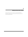
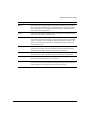
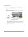
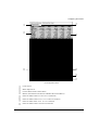
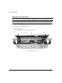
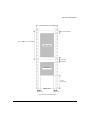
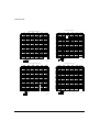
Parts of the Printer
The figures on the previous page show a front, rear and internal view of the printer. The following
parts are indicated:
Front and Left View
1
2
3
4
5
6
Power switch
Platen knob (to feed the paper manually)
Top cover (to protect print head and the printer carriage)
Operator panel (to control the printer)
Cut sheet stand (for the Manual paper path)
Front slot cover (for the Push-Front paper path)
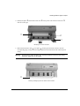
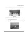
Rear and Right View
7
8
9
0
!
Rear slot cover (for the Push-Rear paper path)
Large rear cover (to facilitate paper feeding device installation in Rear position)
Power socket
Slot for optional Set-Up card or Font card
Interface connectors
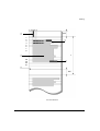
Internal View
"
£
$
%
&
Print head
Print head carriage
Ribbon cartridge supports
Print gap adjustment knob
Print head mask
2-3
Getting to Know Your Printer
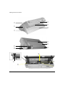
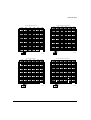
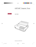
The Ribbon Cartridge
The Ribbon Cartridge contains the inked ribbon which is inserted between the print head and the
paper. The impact of the print head needles on the ribbon applies the ink to the paper.
Your Digital LA400 MultiPrinter can use either a black ribbon or a color ribbon, if the color
mechanism is installed (see section "Preparing for Color Printing" in Appendix A "Supplies and
Options"). The black ribbon cartridge life is 15 million characters.
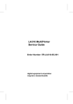
The Black Ribbon Cartridge
1 2
6
3
4
5
d400-b43
1
2
3
2-4
Ribbon Cartridge
Inked ribbon
Ribbon guide
Casing
4
5
6
Back pins
Front pins
Ribbon feed knob
Getting to Know Your Printer
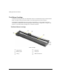
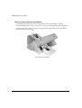
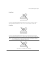
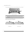
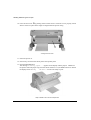
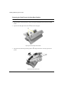
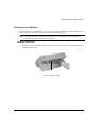
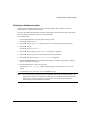
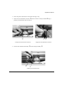
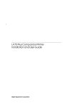
The Push Tractor Unit
The following figure shows you the Push tractor unit which is a paper feeding device used to load
continuous form into the printer.
According to your needs, the Push tractor unit can be mounted in Front position or in Rear
position.
6
1
2
1
2
3
3
Push Tractor Unit
Connector
Connector cover
Tractor
4
5
6
4 5
d400-a53
Tractor door
Tractor pins
Paper supports
2-5
Getting to Know Your Printer
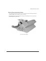
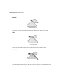
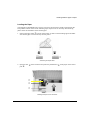
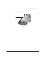
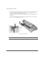
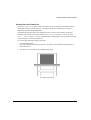
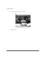
The Push Tractor Unit in Front Position
The mounting of the Push tractor unit in Front position is described at Step 6 "Loading
Continuous Form" in the Setting Up Your Printer section you find at the beginning of this guide.
The Push tractor unit installed in the Front position feeds the paper from the front slot ① and
ejects it through the rear slot ②.
2
1
d4001a15
Push Tractor in Front Position
2-6
Getting to Know Your Printer
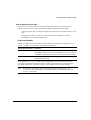
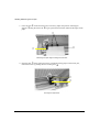
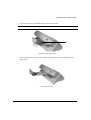
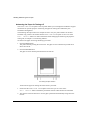
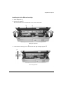
The Push Tractor Unit in Rear Position
The installation procedure of the Push tractor unit in Rear position is described in Chapter 3
"Handling Different Types of Paper" of this User Guide.
With the Push tractor unit in this position, the paper is fed through the rear entry slot and is
ejected through the rear paper slot.
d4001a16
Push Tractor in Rear Position
2-7
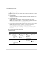
Getting to Know Your Printer
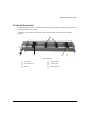
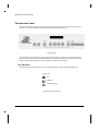
The Operator Panel
The operator panel is positioned on the front right side of the printer. It includes nine function
buttons, a 16-character display, three state and five Paper Path indicators.
Operator Panel
The display shows the messages regarding the printing functions and the operating state of the
printer. You use the buttons to control the printer. The indicator lights show you which function
mode or Paper Path is selected or give information about the printer state.
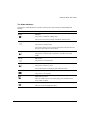
The Indicators
The following graphic conventions are used to describe the possible indicator behaviours:
Off
Lit
Flashing
Flashing rapidly
Indicator Graphic Conventions
2-8
Getting to Know Your Printer
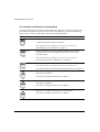
The State Indicators
The Digital LA400 MultiPrinter operator panel has three state indicators: Fault, Ready and
Set-Up.
Indicator State
Meaning
Ready
Ready lit.
The printer is in Ready or Busy state.
The printer can receive printing information from the host.
Ready
Ready off.
The printer is in Pause state.
The printer cannot receive printing information from the host and
the current print tasks are put on hold.
Ready
Ready blinking.
The printer is in Pause state, and there is still data in the input
buffer.
Set-Up
Set-Up off.
The printer is in normal state.
Set-Up
Set-Up blinking slowly.
The printer is in Set-Up state.
See the description of the paper path indicators below.
Fault
Fault lit.
The printer is out of paper.
Fault
Fault blinking slowly.
There is a fault such as cover open, paper jam, communication
error, buffer overflow.
Fault
Fault blinking rapidly.
There is an internal diagnostic fault.
2-9
Getting to Know Your Printer
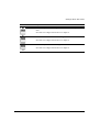
The Paper Path Indicators
The Paper Path indicators identify which Paper Path is selected. A Paper Path is mainly defined
by:
– the paper feeding device used
– the position of the paper feeding device on the printer
Two paper feeding devices are available:
– the Push tractor unit (standard)
– the Pull tractor unit (option)
You can mount the feeding devices in two positions:
– the Front position (under the front slot cover)
– the Rear position (under the rear slot cover)
Caution:
Always remember to power-off the printer before mounting any new paper feeding
device. This allows the printer to automatically detect this device at power-on.
③
④
②
⑤
①
1
2
3
Note:
2-10
Push-Front
Manual
Push-Rear
4
5
1 4
+
Pull (optional)
Reserved
Push+Pull (optional)
Indicators ① and ④ both lit identify the optional Push+Pull Paper Path.
Getting to Know Your Printer
Indicator Status
Meaning
Paper Path indicator lit.
The Paper Path corresponding to the lit indicator is selected. In this
example the Push-Front Paper Path is selected.
Paper Path indicator blinking.
The Paper Path corresponding to the blinking indicator is selected,
but it is out of paper. In this example the Push-Front Paper Path is
out of paper.
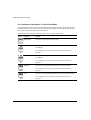
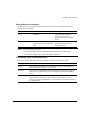
The Buttons
The operator panel buttons are used to control the printer. Their function depends both on the
printer state and on the operating mode you have chosen. See the following section to know the
states and modes definitions.
The main function ① of each button is related to the Normal mode. This function is printed
above the button, in a shaded rectangle.
The secondary functions concern the Set-Up mode, the Top of Form mode or any other specific
mode. These functions are printed outside the shaded rectangle. You access these secondary
functions after first pressing a button as follows:
• you access the secondary functions printed in italic style ② after pressing the Set-Up button
• you access the secondary functions printed in green ③ after pressing the Macro button.
3
1
1
2
Identification of the Button Functions
2-11
Getting to Know Your Printer
The Operating States
The following definitions explain the printer operating states. A state is a specific situation
essentially characterized by the data flow interpretation and the physical configuration of the
printer transmitted through the different sensors. The first part of the display indicates the current
operating state (see the section "The Display" later in this chapter).
Throughout this User Guide, we refer to these definitions.
Operating State
Definition
Ready
- No data are to be printed
- No fault is detected by the sensors
Busy
- Data are to be printed (being printed or not)
- No fault is detected by the sensors
Pause
- Printing is put to hold
- No fault is detected by the sensors
Fault
- A fault is detected by the sensors
- The printer buzzer sounds according to the Set-Up setting, and the
display reads a specific error message
The Operating Modes
The following definitions explain the printer operating modes. An operating mode allows the user
to perform specific operations grouped according to a common function.
Some other feature are also called modes, especially within the Set-Up options. The following
description concerns only the modes that affect how you ues the printer, mainly by using the
button functions.
Throughout this User Guide, we refer to these definitions.
2-12
Getting to Know Your Printer
Operating Modes
Definition
Normal
This is the basic operating mode of your printer, allowing you to perform
all the operations related to getting documents printed: printing, handling
paper, selecting fonts, managing the operating states, switching between
your customized configurations.
Quiet
This is the same mode as Normal, except that printing is performed with a
lower noise level than in Normal mode.
Tear/View
This mode is part of the Normal mode, since it defines the way the paper
moves at the end of each print task or when putting the task on hold (Pause
state). For example, you can make the paper automatically advance to the
tear bar at the end of the print task, or see the last printed line when you
switch to Pause state.
Set-Up
This mode mainly allows you to set-up your printer according to your
operating environment. You can also define 4 customized configurations
depending on the different kinds of jobs you have to manage.
Top of Form
You can quickly access the Top of Form mode (abbreviated to ToF) from
Normal mode in order to modify the position of the first printable line.
Hex-Dump
This is a special printing mode allowing you to check the proper
functioning of your application or your printer.
Adjustment
This mode allows you to perfectly adjust your printer behaviour, in
particular the bidirectional alignment, the position of the first printable line
and the alignment of the paper perforation with the tear bar.
2-13
Getting to Know Your Printer
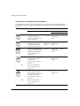
The Function of the Buttons in Normal Mode
As explained previously, the function of the button mainly depends on the operating mode but is
also affected by the printer state. Normal mode gives you direct access to the following button
functions:
Button
Functions
Purpose
Ready/Pause State
Busy State
Fault State
Paper Out
Path
To select one of the
available paper paths.
See "How to Select a Paper
Path" in Chapter 3.
Inactive
Quiet
To toggle between the Quiet
and the Normal modes.
See "Reducing the Print
Noise Level" in Chapter 4.
Same as for Same as for Inactive
Ready/Pause Ready/Pause
state.
state.
Macro
To select one of the Macros
(access to the M1, M2, M3
and M4 button functions).
See "Using Macros" in
Chapter 4.
Inactive
Same as for Inactive
Ready/Pause
state.
LF
LF - To advance the paper
one line at the current
vertical pitch.
See "Moving the Paper" in
Chapter 3.
Inactive
Same as for Inactive
Ready/Pause
state.
M1
M1 - To select Macro 1.
See "Using Macros" in
Chapter 4.
FF/Load
FF/Load - To advance the
Inactive
Same as for Inactive
Ready/Pause
state.
paper. The paper moves
according to the settings of
the Tear/View mode.
See "Moving the Paper" in
Chapter 3.
M2
2-14
Other Fault
M2 - To select Macro 2.
See "Using Macros" in
Chapter 4.
Same as for Inactive
Ready/Pause
state.
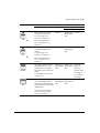
Getting to Know Your Printer
Button
Functions
Purpose
Ready/Pause State
Busy State
Fault State
Paper Out
Font
Font - To force one of the
available resident fonts.
See "Selecting Print
Features" in Chapter 4.
M3
M3 - To select Macro 3.
See "Using Macros" in
Chapter 4.
Pitch
Pitch - To force one of the
available resident pitch
values.
See "Selecting Print
Features" in Chapter 4.
M4
M4 - To select Macro 4.
See "Using Macros" in
Chapter 4.
Pause
To toggle between the Pause Same as for Same as for
Ready/Pause Ready/Pause
and the Ready state. The
state.
paper moves according to
state.
the settings of the Tear/View
mode.
See "Holding a Print Task"
in Chapter 4.
Set-Up
Other Fault
Inactive
Same as for Inactive
Ready/Pause
state.
Inactive
Same as for Inactive
Ready/Pause
state.
Clears the
fault and
returns to
previous state.
See Chapter
11 "Troubleshooting".
To access the Set-Up mode, Same as for Same as for Inactive
Ready/Pause Ready/Pause
the corresponding button
state.
functions and other specific state.
button functions (Park, Print,
Top of Form).
See "The Function of the
Buttons in Set-Up Mode"
later in this Chapter.
2-15
Getting to Know Your Printer
The Function of the Buttons in Set-Up Mode
As explained previously, the function of the button mainly depends on the operating mode. The
printer state also affects the specific function purpose. By definition, you access the following
button functions in Set-Up mode, that is after pressing the Set-Up button.
Button
Functions
Purpose
Park
- With the Push-Rear or Push-Front Paper Paths, to park the paper.
- With the Pull tractor, advances the paper.
Note: This function is no longer active once you enter Set-Up.
See "Handling Continuous Form" in Chapter 3.
Print
Pressing this button the printer prints the firmware version of your
printer and the list of set-up features of the four macros and their
associated values.
Note: This function is no longer active once you enter Set-Up.
See "Printing the Printer Configuration" in Chapter 6.
Top of Form
To access the Top of Form mode.
Note: This function is no longer active once you enter Set-Up.
See "Adjusting the Top of Form from the Operator Panel" in Chapter 5.
D
In Set-Up, to navigate downwards (through Functions, Options,
Sub-options and Values).
See "How to Configure Your Printer" in Chapter 6.
U
In Set-Up, to navigate upwards (through Functions, Options,
Sub-options and Values).
See "How to Configure Your Printer" in Chapter 6.
R
In Set-Up, to navigate at the same level to the next item.
See "How to Configure Your Printer" in Chapter 6.
2-16
Getting to Know Your Printer
Button
Functions
L
Purpose
In the Set-Up structure, to navigate at the same level to the previous
item.
See "How to Configure Your Printer" in Chapter 6.
Sel/Save
To select a Value and save the new Configuration.
See "How to Configure Your Printer" in Chapter 6.
Exit
To exit Set-Up mode without saving the Values.
See "How to Configure Your Printer" in Chapter 6.
2-17
Getting to Know Your Printer
The Functions of the Buttons in Top of Form Mode
As explained previously, the function of the button mainly depends on the operating mode but is
also affected by the printer state. You access the following button functions in the Top of Form
mode, that is after pressing the Top of Form button.
The following table introduces only the buttons active in Top of Form mode.
Button
Function
Purpose
Top of Form
To reset the Top of Form Value to zero.
D
To reduce the Top of Form Value (the paper moves backwards
accordingly).
See "Adjusting the Top of Form from the Operator Panel" in
Chapter 5.
U
To increase the Top of Form Value (the paper moves forwards
accordingly).
See "Adjusting the Top of Form from the Operator Panel" in
Chapter 5.
Sel/Save
To save the Top of Form Value and return to Normal mode.
See "Adjusting the Top of Form from the Operator Panel" in
Chapter 5.
Exit
To return to Normal mode without saving the Top of Form Value.
See "Adjusting the Top of Form from the Operator Panel" in
Chapter 5.
2-18
Getting to Know Your Printer
The Display
The display reads different types of messages according to the printer state and the operating
mode.
The Basic Screen
The basic screen is displayed in Normal mode. It is overwritten with interactive messages which
are described in a section below.
The display is divided in three parts: the printer state ①, the Lock symbol ②, selected
Macro ③, and the current Protocol ④.
1 23 4
The Basic Screen
Printer State Message
Meaning
Ready
The printer is in Ready state.
Busy
The printer is in Busy state.
Pause
The printer is in Pause state.
Quiet
The printer is in Quiet state.
Note: The Quiet message overwrites the other printer state messages.
Lock Symbol
Meaning
The use of a specific font or a specific horizontal pitch is forced (see
"The Font/Pitch Screen").
2-19
Getting to Know Your Printer
Macro Message
Meaning
M1
The Macro 1 is selected.
M2
The Macro 2 is selected.
M3
The Macro 3 is selected.
M4
The Macro 4 is selected.
Protocol Message
Meaning
DEC
The DEC PPL2 protocol is selected.
IPP
The IBM Proprinter XL24E protocol is selected.
AGM
The Alternate Graphic Mode of the IBM Proprinter XL24E protocol is
selected.
EP2
The EPSON ESC/P2 protocol is selected.
Aut (blinking)
The interface type is set to automatic. The printer switches to the protocol
you selected for each type of interface (serial or parallel) when receiving
data.
Hex
The Hexadecimal Dump has been selected.
Note: The Hex message overwrites the other protocol messages.
The Font/Pitch Screen
You access the Font/Pitch screen from the Basic screen after pressing the Font or the Pitch button.
The display is divided in two parts: the selected font ① and the selected horizontal pitch ②.
1
2
The Font/Pitch Screen
2-20
Getting to Know Your Printer
When you first access the Font/Pitch screen, the display reads the following Factory setting for
the font and the pitch:
Font Messages
Pitch Messages
Common Meaning
SoftContrl.
Soft.
Software Control
Draft
10
Software Control means that the font and the pitch that are used by the printer are defined
through the commands of your software application. These messages appear with the font and the
Pitch that will be used if the printer receives no software command.
2-21
Getting to Know Your Printer
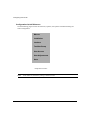
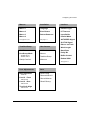
The Different Types of Interactive Messages
The interactive messages can be divided into the groups which are introduced below. See
Appendix C "LCD Display Messages" for a complete list of the display messages.
The User Instruction Messages
These interactive messages are displayed when you have to perform specific operations.
Example:
1. Power-off
2. Push -> Front
This message reminds you to power-off the printer, then to mount the Push tractor unit in the
Front position.
The Printer Status Messages
These interactive messages are displayed to give you specific information on the printer status.
Example:
Top cover open
This message reminds you that the top cover is open, or at least not correctly closed.
The Operating Messages
These interactive messages are displayed to give you additional information on the printer
operating state.
Example:
Loading paper ...
This message indicates that the paper is being loaded through the selected Paper Path.
The Error Messages
These interactive messages are displayed when the printer is in Fault state. The first part identifies
the error, the second part helps you correct the error.
Example:
Comm. failure
Check line
This message indicates that the communication between your printer and the host is not correct
and suggests you check the communication line.
2-22
3
Handling Different Types of Paper
Paper Types
Your printer is able to handle various types of paper: simple or multipart paper for cut sheet or
continuous form. In addition, you can also print on envelopes and labels.
The following specifications should be adhered to in order to assure reliable operation. Paper not
conforming to these specifications may be used with the printer, however, the results are not
guaranteed. A brief test of out-of-specification paper should be performed prior to regular use.
Most paper is sensitive to temperature and humidity conditions and the performance of the paper
may be adversely affected due to extremes in these conditions. To prevent damage, paper,
envelopes and cards should be stored in the original packaging until they are used.
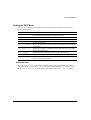
Storage temperature
Storage relative humidity
64° F - 75° F (18° C - 24° C)
40% - 60%
Tips on Paper Quality
Plain bond, typewriter quality paper with a light wood pulp content should be used for optimum
performance. Maximum allowable cotton or rag content is 25%. Papers which should first be
tested prior to regular use are those with a textured, embossed or glossy surface, or a "hammered"
type paper.
Paper must be in pristine condition with no creases or surface or edge damage. Cut sheets must
be flat, not curled or curved.
3-1
Handling Different Types of Paper
Multipart Paper
Multi-parts form demands special consideration because of itscomplexity. Adherence to
tolerances and environmental conditions is more critical than with simple part. The width
tolerances and storage conditions specified for simple part also apply to multipart paper. There
are many different types of multipart paper available; use only snap-out or top-glued forms. Form
sets must be tested prior to regular use.
Side-glued forms glued on both sides are not acceptable. This type of form can trap air bubbles
and are thus more susceptible to skewing. Side glued forms glued on only one side may be used,
though they must be operationally tested prior to regular use.
Envelopes
Envelopes should be tested prior to use. The minimum length of the envelopes that can be
inserted through the manual entry slot is 4" (102 mm).
Note:
For the Paper Specifications, see Appendix B, "Technical Characteristics".
The Paper Paths
One of the main features of your new printer are the many paper paths through which you can
load the paper. According to the type of paper you are using and the paper feed options you are
using, you can define the following paper paths.
For continuous forms the paper path is defined by the paper feeding device used and the position
of this device on the printer.
Warning:
3-2
To ensure proper detection of the paper feeding devices by the printer, always
power-off the printer before mounting a new device or changing the location of a
device.
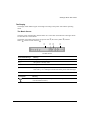
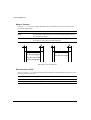
Handling Different Types of Paper
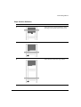
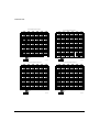
Push-Front
Path-e
The Push-Front Paper Path
Continuous form loaded with the Push tractor unit installed in the front position. The paper is
input into the printer through the front paper slot and is output through the rear paper slot.
Push-Rear
Path-a
The Push-Rear Paper Path
Continuous form loaded with the Push tractor unit installed in the rear position. The paper is
input into the printer through the rear tractor paper slot and is output through the rear paper slot.
Note:
With an additional Push tractor unit two continuous forms can be loaded for alternate
use, one in the Front position and one in the Rear position.
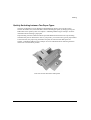
Path-f
Using Push-Front and Push-Rear Tractor Alternatively
3-3
Handling Different Types of Paper
Manual
Path-b
The Manual Paper Path
Cut Sheets, envelopes or particular paper formats loaded through the cut sheet stand.
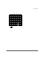
Pull
Path-c
The Pull Paper Path
Continuous form loaded from the front and fed with the Pull tractor unit (option).
Push+Pull
Path-d
The Push+Pull Paper Path
One fanfold paper loaded using both the Pull tractor unit (Option) and the Push tractor unit
installed in Front position.
3-4
Handling Different Types of Paper
How to Select a Paper Path
The selection of the paper path can be done using the printer driver with your application
software. There are also two ways of selecting the paper path operating on the printer.
– using the operator panel, to change the paper path temporarily for a specific need at a given
time
– using the Set-Up mode, to switch to a specific customized Configuration (Macro)
including the use of a dedicated paper path.
Using Set-Up Mode
The Set-Up mode allows you to manage the paper paths used at power-on. Using the PATH AT
POWER-ON Option, you can choose one of the two possibilities:
Path at Power-on Value
Definition
From Macro
The paper path at power-on will be the paper path selected in the
active Macro at power-on. The corresponding PAPER PATH Option
is available in the Macro Option list only when this Value is selected.
Last sel. Path
The paper path at power-on will be paper path selected when the
printer was powered off.
If you select the From Macro Value, select the paper path you intend to use in the PAPER
PATH Option available in the Macro Option list. If the paper feeding device corresponding to
your Macro definition is not present at power-on, the display shows a specific message.
Note:
See Chapter 6 "Configuring Your Printer" for information about the PATH AT
POWER-ON Option and Chapter 7 "Customizing Macros" for information about the
PAPER PATH Option.
3-5
Handling Different Types of Paper
Using the Operator Panel
The Path button on the operator panel is used to select the paper path you want to use. To select a
paper path using the operator panel:
1. Press the Path button.
The indicator corresponding to the currently selected path starts blinking. The display shows
the paper path name.
2. Press the Path button again.
The Path indicators light up one afterone another in counterclockwise order. Only the
indicators of the available paths light up, i.e. those for which the corresponding tractor unit is
installed.
Simultaneously, the display reads the corresponding paper path names.
3. Once the indicator corresponding to the paper path you want to select is lit, release the button.
Automatic paper handling operations depending on your choice are performed after a
time-out.
If the new selected path is out of paper, the corresponding indicator blinks.
The printer will load the paper corresponding to your new paper path selection only when
receiving data.
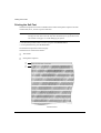
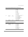
Tips on Selecting the Proper Paper Path
Continuous Form
Paper Path Paper Type
Push
Front
Disadvantages
Not to be used for
strong paper.
Pre-printed forms (with a
large number of copies)
Straight paper
routing
- Simple part
- Multiparts with
Program listings
Paper handling
with standard
printer feeding
device
Adhesive labels paper
with TEAR/VIEW
MODE set to
No tear/reverse
Medium thickness
Limited choice:
Pre-printed forms (with a
large number of copies)
- Simple part
- Multiparts with
Program listings
chemical or carbon
paper
3-6
Advantages
Normal thickness
Wide choice:
chemical or carbon
paper
Push
Rear
Document Type
Maximum print area
Combinable with
the Push-Front, if
you acquire the
additional Push
tractor unit (option)
Paper routing not
straight
Limitation for paper
thickness
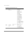
Handling Different Types of Paper
Paper Path Paper type
Pull
Document Type
High thickness
Program listings
Great choice:
Adhesive labels
Advantages
Straight paper
routing
Disadvantages
Specific routing, needs
the optional Pull tractor
Not possible to use other
paper paths
- Simple part
- Multiparts with
chemical or carbon
paper
No reverse paper
movement
Labels with the support
Push+
Pull
Wide thickness
Great choice:
- Simple part
- Multiparts with
chemical or carbon
paper
Pre-Printed forms
(with a large
number of copies)
Program listings
Adhesive labels
with TEAR/VIEW
MODE set to No
tear/reverse
Allows printing on
paper which cannot
be fed with the
Push Front path
Paper driving
reliability
Specific routing, needs
the optional Pull tractor
First part of the paper
cannot be printed. This
paper path may be
incompatible with
printing on preprinted
forms.
Not possible to use other
paper paths.
Note:
Paper with a weight > 100 g/m2 should be operationally tested prior to use. Although the
printer is perfectly able to handle paper of this weight, some of these heavy papers may
have special perforations, which could cause paper jams. See also "Perforation
Anti-Jam" in Chapter 7.
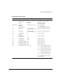
Cut Sheets
Paper Path
Manual
Paper type
Normal thickness
Great choice:
- Simple part
Document Type
Pre-printed forms
Advantages
Best paper routing
Allows printing
without any option
mounted
Disadvantages
Sheet by sheet feeding
- Multiparts with
chemical or carbon
paper
3-7
Handling Different Types of Paper
Envelopes
Paper Path
Manual
Paper Type
Maximum
thickness: 0,3 mm
Document Type
Normal and
preprinted envelopes
Advantages
Best paper routing
Allows printing on
paper without any
option mounted
Disadvantages
Sheet by sheet feeding.
Adhesive Labels
Paper Path
Pull
3-8
Paper Type
According to paper
specifications
Document Type
Adhesive labels
Advantages
No reverse paper
movement
Disadvantages
Not possible to use with
other paper paths
Handling Different Types of Paper
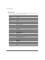
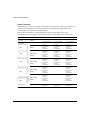
Handling Continuous Form
The Digital LA400 MultiPrinter allows a great number of continuous form handling features. In
addition to the Push-Front and Push-Rear paper paths, the use of the optional Pull tractor unit
gives you access to the Pull and the Push+Pull paper path.
When choosing the paper and paths the following measures apply:
Paper Characteristics
Push-Front
Push-Rear
Pull/Push+Pull
Width
3 to 17
(76 to 432 mm)
3 to 17
(76 to 432 mm)
3 to 17
(76 to 432 mm)
Length
3 to 24
(76 to 609 mm)
3 to 24
(76 to 609 mm)
3 to 24
(76 to 609 mm)
Thickness
max. 0.025
(0.5 mm)
max. 0.014
(0.3 mm)
max. 0.025
(0.5 mm)
Copies
1+5*
Weight
*
1+3
2
1+5*
2
55 to 100 g/m2
Simple part
55 to 100 g/m
55 to 80 g/m
Multiparts
- First part
< 60 g/m2
< 60 g/m2
< 60 g/m2
- Other parts
< 40 g/m2
< 40 g/m2
< 40 g/m2
Carbon paper
35 g/m2
35g/m2
35g/m2
1+7 when selecting the High Impact Draft font.
Note:
Paper with a weight > 100 g/m2 may be used with the printer. It should be operationally
tested prior to use.
3-9
Handling Different Types of Paper
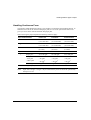
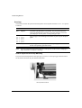
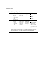
Handling Continuous Forms using the Push Tractorin Front Position
Mounting the Push Tractor Unit in Front Position
Warning:
Before mounting or removing any paper feeding device, power-off the printer.
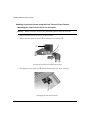
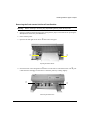
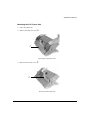
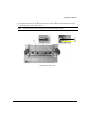
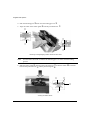
1. Remove the Push tractor unit ① from its plastic packet.
2. Remove the black plastic protection ② from the electrical connector ③.
1
3
2
d4001a02
Removing the Protection from the Electrical Connector
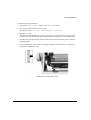
3. Disengage the plastic protection ④ from the feeding motor gear wheel, rotating it.
4
Disengaging the Gear Wheel Protection
3-10
d4001a04
Handling Different Types of Paper
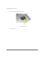
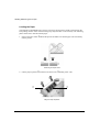
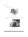
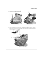
4. Identify the place ⑤ of the Push tractor unit ① in the printer. The electrical connector ③
must be on the right.
5
3
1
d4001a54
Identifying the Tractor Unit Place
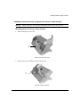
5. Mount the Push tractor unit ① in its place ⑤, inserting the electrical connector into the
corresponding plug on the printer and aligning both its left and bottom sides with the printer
casing.
Warning:
Ensure that the paper separator ⑥ is correctly retracted in the tractor unit casing.
Otherwise, paper may not be loaded.
6
d400-a58
Mounting and Aligning the Push Tractor Unit in its Place
3-11
Handling Different Types of Paper
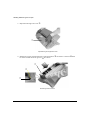
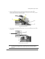
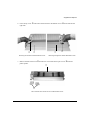
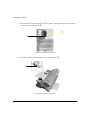
6. Push both the left and right sides of the Push tractor unit
① upward, until it is fully engaged.
1
d4001a07
Engaging the Push Tractor Unit
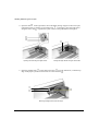
Note:
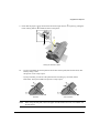
The Push tractor is engaged when you feel and hear the click of both left and right
buttons ⑦. The Push tractor locking buttons must be in the up position as shown in the
following picture.
7. Check that the paper separator ⑥ seats inside the printer and does not overhang the casing.
Position of the Push Tractor Locking Buttons
7
7
d4001a09
d4001a08
Right Position (up)
3-12
Wrong Position (down)
Handling Different Types of Paper
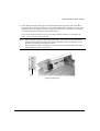
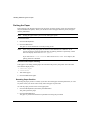
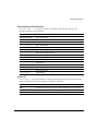
Loading the Paper
Your Digital LA400 MultiPrinter is factory set to have the left tractor already positioned for the
first printable column. Some of the following steps may thus not be necessary. The following
photos show the installation of 80-column paper.
1. Position the paper stack ① in front of the printer as shown in the following figure and make
sure that the paper can be fed freely into the printer.
1
figura1a
Positioning the Paper Stack
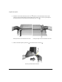
2. Open the door ② of the left tractor and place the pinfeed holes ③ of the paper on the tractor
pins ④.
2
4
3
d4001a10
Installing the Paper on the Left Tractor
3-13
Handling Different Types of Paper
3. Close the door ② of the left tractor and, if necessary, adjust the position of both paper
supports ⑤ along the tractor bar ⑥ to get equal intervals between them and the edges of the
paper.
5
6
2
d4001a11
Positioning the Paper Supports Along the Tractor Bar
4. Open the door ⑦ of the right tractor, then, to facilitate placing paper on the tractor pins,
unlock the tractor by pushing down its locking lever ⑧.
7
8
d4001a13
Unlocking the Right Tractor
3-14
Handling Different Types of Paper
5. If necessary, move the right tractor along the tractor bar ⑥ to position its pins in front of the
pinfeed holes of the paper. Place the pinfeed holes ③ on the same tractor pins as on the left
tractor, so that the top edge of the paper is parallel to the tractor bar.
6
3
d400-a13
Positioning the Right Tractor/Placing the Paper
3-15
Handling Different Types of Paper
6. Close the door ⑦ of the right tractor and check that the left edge of the paper is aligned with
the right edge of the green mark ⑨ on the printer casing. This position allows you to print the
first column against the left side of the printable area (no left margin). If necessary, unlock the
left tractor by pushing down its locking lever, and adjust paper position by moving both
tractors.
If you do not position the paper to print on the first printable column, do not forget to adjust
the LEFT MARGIN Option in Set-Up mode.
9
7
d4005a13
Aligning the Paper Edge with the Green Mark
Note:
3-16
When you aligning the paper edge with the green mark on the printer casing the leftmost
position of the printhead corresponds to the first printable column on the page. It is not
possible to print to the left of the green mark.
Ensure that the left edge of the paper is not outside of the positioning marks. These
marks delimit the paper detection area.
Handling Different Types of Paper
7. Once the paper is properly positioned, lock the left tractor on the tractor bar ⑥ by pushing up
its locking lever and, if necessary, adjust the right tractor position so that the paper is fairly
taut and appears to lay flat on the paper supports.
6
d4002a14
Locking the Tractors
8. Lock the right tractor on the tractor bar ⑥ by pushing up its locking lever.
Caution:
Do not stretch the paper too tightly. The side perforation may tear or the pinfeed
holes may enlarge and cause misfeed or paper jam.
9. Unlock the front cover ⑩ by pulling it with your fingers at its center (put your thumb on the
printer casing to help you).
0
d4001c05
Unlocking the Front Cover
3-17
Handling Different Types of Paper
10. Close the front cover ⑩ by pushing down on both corners. The front cover is properly closed
when it clicks into place and its edges are aligned with the printer casing.
0
d4001c17
Closing the Front Cover
11. Power the printer on.
12. If necessary, select the Push-Front path at the operator panel.
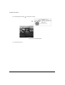
13. Press the FF/Load button.
The message "Loading paper..." appears on the display and the paper is loaded into
the printer. When the paper stops, the Push-Front indicator is on, the Fault indicator is off and
the display shows "Ready
M1-Aut.". You are now ready to print.
d400-a99
Paper Loaded in the Push-Front Paper Path
3-18
Handling Different Types of Paper
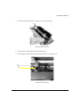
Removing the Push tractor Unit from Front Position
Warning:
Before mounting or removing any paper feeding device, power-off the printer
1. If paper is loaded in the Push-Front paper path, park the paper on the Push tractor pressing the
Set-Up button followed by the Park button.
2. Power-off the printer.
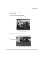
3. Open the left and right tractor doors ① and remove the paper.
1
1
d4001a17
Opening the Tractor Doors
4. Press the tractor unit locking buttons ② down on both sides to unlock the tractor unit ③, pull
it downwards to disengage it and remove it from the printer by rotating slightly.
2
3
d4001a18
Removing the Tractor Unit
3-19
Handling Different Types of Paper
4. Close the gear protection ④ rotating it upwards.
4
Closing the Gear Protection
5. Close the front cover.
3-20
d4002a04
Handling Different Types of Paper
Handling Continuous Forms using the Push Tractor in Rear Position
Warning:
Before mounting or removing any paper feeding device, power-off the printer.
Mounting the Push Tractor in Rear Position
1. Remove the large rear cover ①.
1
d4001c20
Removing the Large Rear Cover
2. Take the rear slot cover ② at the center and remove it.
2
d4001c021
Removing the Rear Slot Cover
3-21
Handling Different Types of Paper
3. Reposition the large rear cover ①.
1
d4001c22
Repositioning the Large Rear Cover
4. Identify the correct insertion direction of the Push tractor ③: the electric connector ④ must
be on the left and the tractor grooves ⑤ face down.
4
3
5
d4005a56
Orientating the Push Tractor
3-22
Handling Different Types of Paper
5. Push the Push tractor unit ③ into the printer on both sides until it engages.
3
d4001a51
Mounting the Push Tractor Unit
Note:
The Push tractor is engaged when you feel and hear the click of both left and right
buttons ⑥. The Push tractor locking buttons must be in the up position as shown in the
following picture.
Position of the Push Tractor Locking Buttons
6
6
d4001a09
d4001a08
Right Position (up)
Wrong Position (down)
3-23
Handling Different Types of Paper
Loading the Paper
Your Digital LA400 MultiPrinter is factory set to have the left tractor already positioned for the
first printing column. Some of the following steps may therefore not be necessary. The following
photos show how to load 80-column paper.
1. Position the paper stack ① behind the printer and make sure that the paper can be fed freely
into the printer.
1
figura4
Positioning the Paper Stack
2. Lift the paper separator ② located on the tractor unit ③ holding both ends.
3
2
d4001a21
Lifting the Paper Separator
3-24
Handling Different Types of Paper
2. Open the door ④ of the left tractor. Insert the paper under the paper separator ②. If
necessary, adjust the position of both paper supports ⑤ along the tractor bar ⑥ to get equal
intervals between them and the edges of the paper
5
4
2
6
d4001c28
Positioning the Paper Supports
3. Insert and place the pinfeed holes ⑦ of the paper on the tractor pins ⑧.Close the door ④ of
the left tractor.
8
7
4
9
d4002a26
Placing the Paper on the Left Tractor
Note:
It is useful to insert the paper about 1 cm inside the rear slot as shown in the figure in
order to facilitate the alignment of the left paper edge with the positioning engraved
marks ⑨.
3-25
Handling Different Types of Paper
0
4. Open the door
of the right tractor, then to facilitate placing of paper on the tractor pins,
unlock the tractor by pushing up its locking lever !. If necessary, move the right tractor
to position the pins in front of the pinfeed holes of the paper.
along the tractor bar
6
!
0
6
d4002a28
Opening and Unlocking the Right Tractor
Moving the Right Tractor along the Tractor Bar
d4003a28
7
8 0
5. Place the pinfeed holes
on the same tractor pins
as on the left tractor, so that the top
edge of the paper is parallel to the tractor bar. Close the door .
7
8
0
d4001a29
Matching the Right Tractor with the Paper
3-26
Handling Different Types of Paper
6. Check that the left edge of the paper is aligned with the right edge of the green mark ⑨ on
the printer casing. This position allows you to print the first column against the left side of the
printable area (no left margin). If necessary, unlock the left tractor by pushing up its locking
lever, and adjust paper position by moving both tractors.
If you do not position the paper to print on the first printable column, you must adjust the
LEFT MARGIN Option in Set-Up mode.
Note:
When you align the paper edge with the green mark on the printer casing, the leftmost
position of the printhead corresponds to the first printable column on the page. It is not
possible to print at the left of the green mark.
Ensure that the left edge of the paper is not outside of the positioning marks area. These
marks delimit the paper detection area.
9
d4002a30
Aligning the Paper Edge
3-27
Handling Different Types of Paper
7. Lock the left tractor on the tractor bar by pushing down its locking lever. If necessary, adjust
the right tractor position so that the paper is moderately taut and appears to lay flat on the
paper supports. Lock the right tractor.
Caution:
Do not stretch the paper too tightly. The side perforation may tear or the pinfeed
holes may enlarge and cause misfeed. Make sure that the paper is taut by moving the
right tractor to the right.
d4003a30
Checking that the Paper is Taut
8. Power the printer on.
9. Press the Path button until the Push-Rear path is selected.
3-28
Handling Different Types of Paper
10. Press the FF/Load button.
The message "Loading paper..." appears on the display and the paper is loaded into
the printer. When the paper stops, the Push-Rear indicator is on, the Fault indicator is off and
the display shows "Ready
M1-Aut.". You are now ready to print.
d4001a16
Paper Loaded in the Push-Rear Paper Path
3-29
Handling Different Types of Paper
Removing the Push Tractor Unit from Rear Position
Warning:
Before mounting or removing any paper feeding device, power-off the printer.
1. Park the paper on the Push tractor unit by pressing the Set-Up button followed by the Park
button.
2. Open the left and right tractor doors ① and remove the paper.
1
d4001c31
Opening the Left and Right Tractor Doors
3. Push down the left and right locking buttons ② and pull the tractor vertically up from the
printer.
2
d4003c56
Removing the Push Tractor Unit
3-30
Handling Different Types of Paper
4. Mount the rear slot cover ③ again by pushing it down into place.
3
d4001a57
Installing the Rear Slot Cover
3-31
Handling Different Types of Paper
Parking the Paper
Paper parking is the function which moves the paper out of the printing sector (the area between
the print head and the platen). When you decide to remove the paper from the printer, the paper
must be parked first.
Note:
Parking the paper allows you to use the other paper paths.
Proceed as follows:
1. Press the Set-Up button.
2. Press the Park button.
The paper is moved backwards out of the printing sector.
Note:
When using the Pull paper path, the function of the Park button is different. As no
reverse movement is allowed with that path, the parking function is replaced by a form
feed. The display shows then Remove paper.
If you select the No tear/reverse Value for the TEAR/VIEW MODE Option, the
parking function is inhibited.
Unsuccessful Paper Parking
If the paper is not totally parked (paper still inserted in the printer), the printer enters the Fault
state and the display shows:
1. Tear-off paper
2. Press Park
1. Tear-off the paper.
2. Press the Park button again.
Resetting Paper Position
Resetting the paper position is useful, if you have moved the paper with the platen knob, or if for
any other reason you do not know exactly where the paper is positioned.
To reset the paper position in the current paper path:
1. Press the Set-Up button, followed by the Park button.
The printer parks the paper.
2. Press the FF/Load button.
The paper is positioned with the first printable line facing the print head.
3-32
Handling Different Types of Paper
Printing on Cut Sheets
Your printer gives you the possibility to print also on cut sheets, which are loaded through the cut
sheet stand on the front part of the printer, using the Manual paper path.
Note:
The Manual paper path is always available as soon as you insert a sheet. The path is
automatically selected and the sheet is loaded.
Loading Cut Sheets
1. Open the Cut sheet stand ① by pushing it down on the tab in the center of the stand as shown
in the following picture.
1
d4001a34
Opening the Cut Sheet Stand
3-33
Handling Different Types of Paper
2. Position the left paper guide ② against the third large mark of the cut sheet stand and present
a sheet without actually inserting it into the slot. Check that the left edge of the paper is
aligned with the right edge of the third large mark ③.
This position allows you to print the first column against the left side of the printable area (no
left margin).
If you do not position the paper to print on the first printable column, do not forget to adjust
the LEFT MARGIN Option in Set-Up mode.
2
3
Caution:
3-34
d402a43
Positioning the Left Paper Guide
Do not engage the sheet over the black area or a paper jam may occur.
Handling Different Types of Paper
3. Adjust the right paper guide ④ according to the cut sheet width.
Note:
Be careful not to fold the sheet.
4
d4001c27
Adjusting the Right Paper Guide
4. Insert the sheet in the slot until it stops against the paper feed rollers. Carefully follow the
paper guides.
d4001a37
Inserting the Cut Sheet
3-35
Handling Different Types of Paper
5. Hold the sheet against the rollers until they load the paper.
The message "Loading paper..." appears on the display and the paper is fed to the first
printable line, according to Set-Up settings.
Note:
It is not necessary to select the Manual paper path before inserting the sheet. The
selection is performed automatically by the printer.
Ejecting Cut Sheets
When a cut sheet is inserted in the printer, to eject it press the FF/Load button.
3-36
Handling Different Types of Paper
Printing on Adhesive Labels
When printing on adhesive labels, use one of the straight paths, that is Push-Front, Pull or
Push+Pull. Do not use the Push-Rear path.
You must also disable the backward movement of the paper, because the unsticking of the labels
can cause paper jams when the paper is moved backwards.
Proceed as follows:
1. Press the Set-Up button to put the printer in Set-Up mode.
The display shows MACROS.
2. Press the D button. MACRO X is displayed, where X is the number of the current Macro.
3. Press the D button.
The display shows PROTOCOL.
4. Press the R button until the TEAR/VIEW MODE Option is displayed.
5. Press the D button to pass over to the Values for the Tear/View mode.
6. Press the R or L button, until No tear/reverse is displayed.
7. Press the Sel/Save button to set confirm the new setting. An asterisk is displayed to indicate
that the Value has been selected.
8. Press the Exit button to exit the Set-Up mode.
The message "Save config." appears, indicating that you are going to save your new
setting.
9. To permanently save your choice, press the Sel/Save button.
Note:
Is is not necessary to perform the above operation when using the Pull paper path, as all
backwards movements are inhibited with this path. We reccommend using the Pull path
when printing on adhesive labels, but note however that the printing of landscape
barcodes may generate backward movements.
3-37
Handling Different Types of Paper
Moving the Paper
To move the paper we recommend you to only use the operator panel buttons:
• LF:
Advances the paper one line at the current vertical pitch.
• FF/Load:
Advances the paper depending on the setting of the TEAR/VIEW MODE Option.
See Chapter 6 "Configuring Your Printer".
Note:
Use only the platen knob to recover from paper jams. Always reset the paper position
after moving the paper with the platen knob.
d400-a57
Moving the Paper with the Platen Knob
3-38
Handling Different Types of Paper
Viewing the Last Printed Line
The TEAR/VIEW MODE Option of the Set-Up allows you to manage the automation of paper
movements related to specific purposes. Viewing the last printed line during a print task is
affected by this automation management.
The following description shows an example of how to use your printer features in the most
automatic way possible. We assume that the TEAR/VIEW MODE Option is set to one of the
Auto. advance Values. For more information about managing the viewing of the last printed
line, see Chapter 7 "Customizing Macros".
To view the last printed line during a print task:
1. Press the Pause button.
The printer finishes printing the current line. The paper is fed so that the last printed line is
above the tear bar.
2. To resume your print task, press the Pause button again.
pos4
The Viewing Paper Position
3-39
Handling Different Types of Paper
Advancing the Paper for Tearing-off
The TEAR/VIEW MODE Option of Set-Up mode allows you to manage the automation of paper
movements for specific purposes. Advancing the paper for tearing-off is affected by this
automation management.
The following description shows an example of how to use your printer features in the most
automatic way possible. We assume that the TEAR/VIEW MODE Option is set to one of the
Auto. advance Values. For more information about managing the advancing the paper for
tearing-off, see Chapter 7 "Customizing Macros".
To advance the paper for tearing-off during a print task:
1. Press the Pause button.
The printer finishes printing the current line. The paper is fed so that the last printed line is
above the tear bar.
2. Press the FF/Load button.
The paper is fed so that the perforation faces the tear bar.
pos5
The Tearing-off Paper Position
To advance the paper for tearing-off at the end of a print task:
1. Ensure that the TEAR/VIEW MODE Option in the Set-Up is set to one of the
Auto. advance Values and that the printed file includes a final Form Feed command.
2. Just wait the end of the time-out to see the paper perforation automatically being fed to the
tear bar.
3-40
4
Operating Your Printer
Using Macros
About Macros
A Macro is a set of pre-determined parameters allowing you to adapt your printer to your
particular need. Your printer comes with four different Macros. You can customize the four
Macros according to your specific needs by using Set-Up mode.
Note:
For more information about using Set-Up mode, see Chapter 6 "Configuring your
Printer".
In addition to the Macro, you also have to adapt the entire printer configuration by selecting other
parameters defining the interface, the installation, the user adjustments etc. For the LA400
MultiPrinter, such parameters are called Values. These Values are sorted within Functions,
Options and Sub-options. The Macro is one of the Functions within the printer Configuration.
The Macro Options are described in Chapter 7 "Customizing Macros".
Macro Option Samples
Sub-options
Values
Protocol
Protocol-Serial
DEC PPL2
IBM XL24E
EPSON ESC/P2
Protocol-Parallel
DEC PPL2
IBM XL24E
EPSON ESC/P2
Font
Draft
High Impact Draft
...
4-1
Operating Your Printer
Switching between Macros
To switch between the Macros:
1. Press the Macro button ① on the operator panel.
The display shows Select a Macro.
1
2
Selecting a Macro
2. Within 3 seconds press the M1, M2, M3 or M4 button ② corresponding to the Macro you want
to use.
The printer initializes the Values of the Macro (the display shows Processing ...).
The basic screen then indicates the new current Macro.
Note:
4-2
The Macro at power-on is the current Macro when you power-off the printer.
Operating Your Printer
Selecting Print Features
There are three possibilities to select the print features you need for a specific print task:
• By customizing a Macro.
This allows you to alter the greatest number of print parameters. Within the Option list of the
Macros, you can define:
– the page layout (form dimensions, margins ...)
– the publishing style (font, character set, character spacing, line spacing, contrast of the
print-out ...)
– the printer behaviour (blank pages management, DEC mode management ...)
See Chapter 7 "Customizing a Macro" for more details.
• By using a printer driver.
This technique reduces the number of print parameters you can alter. Please note that the
parameters available in the printer driver dialog boxes override the corresponding parameters
of the printer Set-Up.
• By using the operator panel.
This allows you can alter the font and the horizontal pitch using the corresponding buttons.
See the following sections for details.
4-3
Operating Your Printer
Selecting the Font
The Font button allows you to select one of the following resident fonts:
Draft - HiDraft - Courier - Roman - Sans Serif - Prestige - Script - Orator - OCR-A - OCR-B
You can also select the SoftContrl (Software Control) Value. Software Control means that the
font that is used by the printer is defined through the commands of your software application.
This message blinks alternately with the Font that will be used if the printer receives no software
command.
To select a resident font:
1. Press the Font button.
2. Within 3 seconds press the Font button, until the desired font is displayed (keeping the button
depressed displays the different fonts continuously.
Three seconds after releasing the button, the display shows the basic screen again and the font
is set.
Note:
- If a font is selected using the Font button, it is locked and cannot be changed by
software commands. The basic screen then shows then the Lock symbol.
- The font selection made using the Font button is canceled as soon as you power-off the
printer.
To return to Software Control, press the Font button, until SoftContrl is displayed.
4-4
Operating Your Printer
Selecting the Pitch
The Pitch button on the operator panel allows you to select different horizontal pitches according
to the selected protocol. See Chapter 7 "Customizing a Macro" for the pitch values.
You can also select the Soft. (Software Control) Value. Software Control means that the pitch
that is used by the printer is defined through the commands of your software application. This
message blinks alternately with the Pitch that will be used if the printer receives no software
commands.
To select a pitch:
1. Press the Pitch button
2. Within 3 seconds press the Pitch button, until the desired pitch is displayed (keeping the
button depressed displays the different pitches continuously.
Three seconds after releasing the button, the display shows the basic screen again and the
pitch is set.
Note:
- If a pitch is selected using the Pitch button, it is locked and cannot be changed by
software commands. The basic screen then shows then the Lock symbol.
- The pitch selection made using the Pitch button is canceled as soon as you power-off
the printer.
To return to Software Control, press the Pitch button, until Soft. is displayed.
Holding a Print Task
To hold printing temporarily:
• Press the Pause button.
The Ready indicator blinks, indicating that there are still data to be printed. The paper moves
according to the settings of the TEAR/VIEW MODE Option.
To resume printing:
• Press the Pause button again.
4-5
Operating Your Printer
Reducing the Print Noise Level
To print with a reduced noise level (Quiet mode).
• Press the Quiet button.
The display shows Quiet instead of the current printer state.
To return to Normal mode:
• Press the Quiet button again.
The display shows printer state that was active before pressing the Quiet button.
Recovering from a Fault State
Recovering from a Paper out Fault
If the printer is out of paper, the Fault and Ready indicators are lit and the display shows the
Load X message, where X is the current Paper Path.
1. Make sure that paper is loaded in the current paper path.
2. Press the FF/Load button.
The display shows Loading... and paper is loaded.
Note:
If no paper is installed in the current Paper Path, see Chapter 3 "Handling Different
Paper Types" for the paper installation procedure.
Recovering from other Faults
To recover form any other Fault state:
1. Remove the cause of the Fault state.
2. Press the Pause button, to clear the Fault state.
Note:
4-6
It may happen, that two Fault states occur at the same time. In this case press the Pause
button repeatedly, until both of them are cleared.
5
Printing
Print Area Definition
For the correct definition of the print area, customize the printer Set-Up Macros according to
your needs.
The corresponding Options are the following:
•
•
•
•
•
•
FORM LENGTH
LEFT MARGIN
FORM WIDTH
TOP MARGIN
BOTTOM MARGIN
TOP OF FORM
See Chapter 7 "Customizing a Macro" for a complete description of these Options.
Note:
The physical print area limitations are described in Appendix B "Technical
Characteristics".
5-1
Printing
Print Area Definition
• ToF (Top of Form) :
This value defines the distance between the edge of the paper and the place where you allow
the printing to begin (position of Line #1). You can adjust this distance according to the
condition of your paper (for example pre-printed forms). When you load the paper, the printer
feeds the paper so that the print head faces Line #1, waiting for printing commands.
• L (Form Length):
Set the Option (FORM LENGTH) according to the actual physical page length (the distance
between two perforations for continuous forms). This will allow the printer to know exactly
where the print head is and to position it at the same position when a form feed occurs.
• Top line ①:
This is the line where the printing actually starts. To define a top margin, select the number of
this line. Example: In the following picture TOP MARGIN Option is set to 3.
• Bottom line ②:
This is the line where the printing actually stops. To define a bottom margin, select the number
of this line. Example: In the following picture BOTTOM MARGIN Option is set to 50.
• Left column ③:
This is the column where the printing actually starts. To define a left margin, select the number
of this column. Example: In the following picture LEFT MARGIN Option is set to 4.
• Print area ④:
Print area defined by the corresponding Macro Options: FORM LENGTH, TOP OF FORM,
TOP MARGIN and BOTTOM MARGIN.
• Paper perforation ⑤:
The perforation defines the physical page length.
5-2
Printing
3
4
5
123456
TOF
1
2
3
4
5
6
7
8
.
.
.
.
48
49
50
51
1
ABCDEFGHIJ...
ABCDEFGHIJ...
L
ABCDEFGHIJ...
2
TOF
Print Area Definition
5-3
Printing
Printing on Multipart Form
Once you have decided which paper format you are using, you can start sending the print tasks.
The printer loads the paper in the current paper path as soon as it receives data.
If you are using application software which uses the printer driver to manage the print jobs, make
sure that the Paper Format and the Print Area match the paper installed on the printer.
Adapting to Paper Thickness
For good print quality and correct paper feeding, you should adapt the print impact strength and
the print gap to the paper thickness. Your printer is factory set to adjust automatically, as it allows
you to get the best printing results in most cases without any intervention. Select one of the other
values only for special print tasks.
Two Macro menu Options are available to adapt the printer to specific paper thickness.
• The PRINT GAP Option defines the distance between the print head and the platen.
– If you set the automatic adjustment (Auto.adjust Value) for the print gap the printer
senses the paper thickness each time you load the paper and adjusts the gap accordingly.
This is the factory setting, as it allows you to get the best printing results in most cases
without any intervention. Select one of the other Values only for special print tasks. When
you select this Value, set, if necessary, the corresponding AUTO.GAP OFFSET Option.
– The print gap can also be set according to the number of parts of the paper (For X
parts Values).
– By setting the manual adjustment (Manual adjust. Value), you can adjust the print
gap manually by using the print gap adjustment knob.
• The PRINT IMPACT Option gives you the possibility to choose between two print head
impact strengths.
– The factory setting Soft impact Value should be used for normal paper
– The Strong impact Value should be used for multipart form in order to obtain good
quality printing for all copies.
5-4
Printing
Hints on Printer Settings for Paper Thickness
Before starting the print job you should print some sample pages to test the print result of the
different settings.
• Always set the PRINT IMPACT and the PRINT GAP Options to be compatible.
For example, if you set the For 5 parts Value for the PRINT GAP Option and you do
not set the PRINT IMPACT Option to Strong impact, you may not have satisfactory
print quality on the last part of the multipart form.
• Avoid printing with Strong impact strength on thin paper. This could damage the paper
and the platen.
• The Manual adjust. Value of the PRINT GAP Option does not allow very precise print
gap adjustment and should be used only for special paper, when other settings have not
produced satisfactory results.
Note:
For more details about the paper thickness setting, see the section "Setting the Printing
Modes" in Chapter 7 "Customizing Macros".
Managing Blank Pages
Thanks to the Tear/View mode feature for advancing paper for tear off, your Digital LA400
MultiPrinter allows you to save paper by removing unnecessary blank pages between print jobs.
To remove unnecessary blank pages:
• Select the Removed Value for the BLANK PAGES Macro Option.
To preserve blank pages voluntarily inserted within a print task:
• Select the Preserved Value for the BLANK PAGES Macro Option.
5-5
Printing
Printing on Pre-printed Forms
When printing on Pre-printed forms, you may need to reposition the paper in order to align the
printout with the predefined areas on the paper. This operation is performed by adjusting the Top
of Form Value (see the Top of Form definition in the section" Print Area Definition", above).
You can access the Top of Form setting, either in the Macro Option List in Set-Up mode or
simply from the operator panel. The operator panel allows you to modify the Top of Form setting
either temporarily or permanently.
Adjusting theTop of Form from the Operator Panel
Adjusting the Top of Form from the Operator Panel affects the current Macro setting if you
decide to permanently save your setting.
Proceed as follows:
1. Press the Set-Up button.
2. Press the Top of Form button. The printer loads the paper in the current paper path. The
display shows the current Top of Form value.
3. Press the U or D button to move the paper position respectively up or down in steps of 1/60
inch. The new Top of Form value appears on the display.
4. When the desired setting is reached:
– to temporarily save the Top of Form Value, press the Exit button
– to permanently save the Top of Form Value, press the Sel/Save button.
The paper moves back to its previous position.
To reset the Top of Form Value:
• If you want to quickly reset the Top of Form Value to 0/60 inch, press the Top of Form button
during the procedure described above.
The paper moves to the corresponding Top of Form Value, then returns to its previous position.
5-6
Printing
Quickly Switching between Two Paper Types
The basic configuration of your Digital LA400 MultiPrinter allows you to quickly switch
between the Push-Front (or the Push-Rear) and the Manual paper paths, by simply pressing the
Path button at the operator panel. See Chapter 3 "Handling Different Types of Paper" for more
information about selecting a paper path.
Paper handling is further enhanced with the optional additional Push tractor unit. By mounting
simultaneously the two Push tractor units on your printer, you can have two types of paper loaded
at the same time, one paper using the Push-Front path, the other the Push-Rear path. See
Chapter 3 "Handling Different Types of Paper" for more information about mounting the Push
tractor unit in Front or Rear position.
Push-Front and Push-Rear Paths Used Together
5-7
Configuring Your Printer
6
Configuring Your Printer
What is Configuration?
Configuration is the whole set of parameters that define the printer usage characteristics such as
communication interface, protocol, fonts, paper path etc. Configuring your printer is necessary to
make it operate and communicate properly with your hardware and software.
You access the Configuration using Set-Up mode. Set-Up mode provides seven configuration
Functions:
• MACROS
This Function lets you customize the four Macros, which are designed to quickly adapt your
printer to different kinds of print tasks.
• INSTALLATION
This Function contains generic parameters such as the language used for the display.
• INTERFACE
This Function lets you define the interface type and to set the communication characteristics.
• TEST/HEX-DUMP
This Function is dedicated for testing your printer with the self test or switching to hex-dump
mode.
• USER ACCESS
This Function defines the access authorization to the Set-Up Options.
• USER ADJUSTMENTS
This Function allows fine adjustment of all the mechanical parameters, such as the print gap,
the position of the first printable line etc.
• SAVE
This Function allows you to manage your configuration in the section "Reaching, Selecting
and Saving a Configuration Value" later in this chapter.
6-1
Configuring Your Printer
The Configuration Structure
The Set-Up Configuration contains seven Functions, which group specific Options. The Options,
if necessary, are broken down into other Sub-options. The selectable parameters defining the
Options or Sub-options are called Values. The following is an example of part of the
Configuration structure.
Function Level
Options Level
Sub-options Level
Values Level
Macro
Protocol
Protocol-Serial
DEC PPL2
IBM XL24E
EPSON ESC/P2
Protocol-Parallel
DEC PPL2
IBM XL24E
EPSON ESC/P2
Font
Draft
Hi Draft
...
Vertical Pitch
2 lpi
1 lpcm
...
In the above table, the Protocol Option has two Sub-options: Protocol-Serial and
Protocol-Parallel. You have to choose one of these Sub-options to access the selectable values.
The Font and the Vertical Pitch have not Sub-options: you access to the selectable Values directly.
6-2
Configuring Your Printer
Display Graphic Conventions
To allow you to recognize the kind of item that appears on the printer display, the following
graphic conventions apply:
Display Sample
Convention
Meaning
MACRO
Uppercase
This convention applies to
Functions, Options and
Sub-options (all non-selectable
items).
Lower case with initial cap
* symbol for the current/selected
Value
This convention applies to the
selectable Values and to the
executable Values
*
Note:
English
There are two types of values:
- the selectable Values which are parameters that alter the printer Configuration.
- the executable Values which generate immediate operations
The Different Types of Selectable Values
Three types of selectable Values have been defined, according to how they are saved.
Value Type
Meaning
Factory
These are the Values that are set at the factory. You can recall them for the
entire Configuration using the SAVE Option.
Power-on
These are the values that are active when powering-on the printer. They are
active when you permanently save your changes by pressing the Sel/Save
button.
Current
These are the values that are active at a given time and that are lost when you
power-off the printer. They are active when you temporarily save your
changes by pressing the Exit button, or by modifying corresponding Values at
the operator panel.
6-3
Configuring Your Printer
Configuration Quick Reference
See the following pages to know the Functions, Options, Sub-options and Values defining the
entire Configuration.
Macros
Installation
Interface
Test/Hex-Dump
User Access
User Adjustments
Save
Configuration Functions
Note:
6-4
In the Value list, the Factory setting is shown in bold.
Configuring Your Printer
Macros
Installation
Interface
Macro 1
Language
Interface Type
Macro 2
Error Buzzer
I/F Time-out
Macro 3
Path at Power-on
Input Buffer
Parallel Mode
Macro 4
See pages 6-6, 6-7
See page 6-7
AUTOFEED Signal
SLCT-IN Signal
Discon. on Fault
Test/Hex-Dump
User Access
Word Length
Self-Test
All Functions
Baud Rate
Hex-Dump Mode
Macros
Parity Bit
Test/Hex-Dump
Buffer Control
Minimum
Robust XON
Enable Hex-D.
Disable Hex-D.
SetUp Card init.
See page 6-11
User Adjustments
Save
Bidi. Alignment
Save Config.
Offset: X
Line #1 - Front
X/60 inches
Line #1 - Rear
Restore Macro X
Rest.all Macros
Recall Factory
X/60 inches
Tear-Perfo Align
X/60 inches
6-5
Configuring Your Printer
1/2
Macro 1/2/3/4
Protocol
Protocol Serial
DEC PPL2
EPSON ESC/P2
IBM XL24E
Protocol Paral.
DEC PPL2
EPSON ESC/P2 (M1/M3)
IBM XL24E (M2/M4)
Font
Draft
HiDraft
Courier
Roman
SansSerif
Prestige
Script
Orator
OCR-A
OCR-B
Vertical Pitch
2 lpi
3 lpi
4 lpi
6 lpi
8 lpi
10 lpi
12 lpi
1 lpcm
2 lpcm
4 lpcm
Form Length
3 inches
3.5 inches
4 inches
5.5 inches
6 inches
7 inches
8 inches
8.5 inches
11 inches(A)
A4(11.6 inches)
12 inches
14 inches
15 inches
Number of Lines
X lines (1 to 256)
Form Width
8 inches
13.2 inches
13.6 inches
Top Margin
Line #X (1)
Bottom Margin
Line #X (66)
Left Margin
Column #X (1)
Unidirectional
Bidirectional
Soft. Control
Line Mode
LF=LF,CR=CR
LF=LF+CR
CR=LF+CR
LF&CR=LF+CR
Blank Pages
Removed
Preserved
Perfo. Anti-jam
Enabled
Disabled
Print Gap
Auto. adjust.
For 1 part
For 2 parts
For 3 parts
For 4 parts
For 5 parts
For 6 parts
Manual adjust.
Auto Gap Offset
0 (-8 to +8)
Top of Form
0/60 inches
(0/60 " to 127/60 ")
Paper Path
Push-Front
Push-Rear
Manual
6-6
Print Direction
Print Impact
Soft impact
Strong impact
Configuring Your Printer
2/2
Macro 1/2/3/4
Tear/View Mode
Auto.advance 1s
Auto.advance 2s
Auto.advance 3s
Auto.advance 4s
Auto.advance 5s
Manual advance
No tear/reverse
DEC Mode
Horizontal Pitch
G0 Character Set
User Pref. C-Set
Wrap vs Truncate
Printer ID
Disconnect./EOT
Init. Report
Auto. ANSWERBACK
ANWERBACK/ENQ
IBM Mode
Horizontal Pitch
IBM C-Set
Code Page
IBM Dbl. Height
IBM AGM
Pitch/COMPRESS
Slashed Zero
See page 6-9
EPSON Mode
Horizontal Pitch
National C-Set
Code Page
EPSON C-Set
Slashed Zero
Installation
Language
English
Deutsch
Español
Français
Italiano
Error Buzzer
1 beep
3 beeps
Continuous beep
No beep
Path at Power-on
From Macro
Last sel. Path
See page 6-10
See page 6-8
6-7
Configuring Your Printer
DEC Mode
Horizontal Pitch
5 cpi
6 cpi
6.6 cpi
8.25 cpi
8.55 cpi
9 cpi
10 cpi
12 cpi
13.2 cpi
15 cpi
16.5 cpi
17.1 cpi
18 cpi
20 cpi
Prop. Spacing
User Pref. C-Set
DEC Supplement.
DEC Spec.Graph.
DECTechnical
DEC 7Bit Hebrew
DEC Hebrew Sup.
DEC Greek Sup.
DEC 7Bit Turk.
DEC Turk. Sup.
JIS Katakana.
ISO Latin-1
ISO Latin-2
ISO Latin-5
ISO Lat.-Hebrew
ISO Latin-Greek
ISO Lat.-Cyril.
6-8
G0 Character Set
US ASCII
British
DEC Finnish
French
DEC French-Can.
German
ISO Italian
JIS Roman
DEC Norw./Dan.
ISO Spanish
DEC Swedish
Norw./Danish
DEC Dutch
DEC Swiss
DEC Portuguese
Legal
DEC Supplement.
DEC Spec.Graph.
DECTechnical
DEC 7Bit Hebrew
DEC Hebrew Sup.
DEC Greek Sup.
DEC 7Bit Turk.
DEC Turk. Sup.
JIS Katakana
Wrap vs Truncate
Wrap
Truncate
Printer ID
PPL2
LA120 ID
LA210 ID
Disconnect./EOT
Disabled
Enabled
Init. Report
Disabled
Enabled
Auto.ANSWERBACK
Disabled
Enabled
ANSWERBACK/ENQ
Disabled
Enabled
Configuring Your Printer
IBM Mode
Horizontal Pitch
10 cpi
12 cpi
17.1 cpi
20 cpi
Prop. Spacing
IBM C-Set (1/2)
IBM set 1
IBM set 2
Code Page
Code Page 210
Code Page 220
Code Page 437
CP 437 Greek
Code Page 850
Code Page 852
Code Page 853
Code Page 855
Code Page 857
Code Page 860
Code Page 861
Code Page 862
Code Page 863
Code Page 864
Code Page 865
Code Page 866
Code Page 869
Abicomp
Brazilian ASCII
Mazowian
Code MJK
Bulgarian
ISO 8859-7
ISO Latin 1T
New Hebrew
D-Hebrew
IBM Dbl. Height
Disabled
Enabled
IBM AGM
Disabled
Enabled
Pitch/COMPRESS
17.1 cpi
20 cpi
Slashed Zero
No
Yes
6-9
Configuring Your Printer
EPSON Mode
Horizontal Pitch
10 cpi
12 cpi
17.1 cpi
20 cpi
Prop. Spacing
National C-Set
USA
France
Germany
United Kingdom
Denmark 1
Sweden
Italy
Spain 1
Japan
Norway
Denmark 2
Spain 2
Latin America
Turkey
Korea
Legal
Old Hebrew
6-10
Code Page
Code Page 210
Code Page 220
Code Page 437
CP 437 Greek
Code Page 850
Code Page 852
Code Page 853
Code Page 855
Code Page 857
Code Page 860
Code Page 861
Code Page 862
Code Page 863
Code Page 864
Code Page 865
Code Page 866
Code Page 869
Abicomp
Brazilian ASCII
Mazowian
Code MJK
Bulgarian
ISO 8859-7
ISO Latin 1T
New Hebrew
D-Hebrew
EPSON C-Set
Graphic
Italic
Slashed Zero
No
Yes
Configuring Your Printer
Interface
Interface Type
Automatic
Parallel
Serial
SLCT-IN Signal
Disabled
Enabled
Parity Bit
None
Even
Odd
Discon. on Fault
I/F Time-out
2 seconds
(2 to 30 seconds)
Input Buffer
1 K (DLL)
8 K (No DLL)
16 K (No DLL)
32 K (No DLL)
Parallel Mode
Bidirectional
Centro
AUTOFEED Signal
Disabled
Enabled
No discon.
Yes (DTR drop)
Yes (DTR pulse)
Word Length
8 bit
7 bit
Buffer Control
XON/XOFF
XON/XOFF + DTR
DTR
Robust XON
No
Yes
Baud Rate
600 bps
1200 bps
2400 bps
4800 bps
9600 bps
19200 bps
38400 bps
6-11
Configuring Your Printer
How to Configure your Printer
Reaching, Selecting, Saving a Configuration Value
When you press the Set-Up button, the printer enters Set-Up mode allowing you to navigate
within the Configuration structure. Use the Arrows buttons to move around in the structure.
Reaching a Configuration Item
Button
UD
RL
Purpose
To switch from an item level to another (upwards or downwards).
Within the same level, to switch from an item to another (forwards or
backwards).
Selecting a Configuration Value
When you reach a Value (selectable or not), press the Sel/Save button to select it or to perform
the corresponding action.
Saving the new Configuration
When you have finished selecting the Values, press the Exit button. The display shows
Save Config.
• To permanently save all the changes you made, press the Sel/Save button.
All your changes become the power-on Values for the entire Configuration.
• To temporarily save the changes made for the current Macro only, press the Exit button.
The changes made for the current Macro only become its current Values. (Column
CURRENT VALUES of the Configuration Sheet).
6-12
Configuring Your Printer
Example Configuring
The following is an example Configuration procedure, in which we will alter the Factory settings:
the font is changed from Draft to Orator and the horizontal pitch is changed from 10 cpi to
17.1 cpi in DEC protocol for Macro 2.
1. Press the Set-Up button to put the printer in Set-Up mode.
MACROS is displayed.
2. Press the D button.
The display shows MACRO 1.
3. Press the R button.
The display shows MACRO 2.
4. Press the D button.
The display shows PROTOCOL.
5. Press the R button until FONT is displayed.
6. Press the D button.
The display shows *
Draft.
7. Press the R or L button, until the display shows Orator.
8. Press the Sel/Save button to select this font.
An asterisk is displayed to indicate that the Value has been selected.
9. Press the U button to return to the Options level.
The display shows FONT.
10. Press the R or L button, until the display shows DEC MODE.
11. Press the D button to pass over to the value setting for the DEC defaults, the display shows
HORIZONTAL PITCH.
12. Press the D button.
The display shows 10 cpi.
13. Press the R or L button, until the display shows 17.1 cpi.
14. Press the Sel/Save button to select the horizontal pitch.
An asterisk is displayed to indicate that the value has been selected.
6-13
Configuring Your Printer
15. Press the Exit button. The display shows Save config..
17. To permanently save your changes, press the Sel/Save button.
The display shows Processing..., indicating that the parameters are copied in the
printer memory.
Printing the Printer Configuration
To check the values set in the printer Configuration, proceed as follows:
1. Press the Set-Up button.
2. Press the Print button.
The printer prints the current printer Configuration.
See the figure on the next page
Note:
- Values that are not applicable are printed in italic style.
- Depending on specific interdependent settings, Programmed may be printed instead
of a numeric value.
Tips for Configuring
• First print the Configuration Sheet to see the current settings.
• Once you are familiar with the Arrow button functions, use the Configuration Quick Reference
to quickly reach the items you need.
6-14
Configuring Your Printer
1
2
3
4
5
6
7
8
1
3
2
4
8
5
6
7
The Configuration Sheet
Code version
Macro Option List
Current Values of the current Macro
Macros (the asterisk in the title bar identifies the current Macro)
Power-on Values of the INSTALLATION Function
Power-on Values of the USER ADJUSTMENTS Function
Power-on Value of the USER ACCESS Function
Power-on Values of the INTERFACE Function
6-15
Configuring Your Printer
How to Manage your Configuration
The SAVE Function allows you to manage your printer Configuration.
Function
Executable Values
SAVE
Save Config.
Restore Macro X
Rest.all Macros
Recall Factory
You scroll the Values pressing the R or L button.
Saving a Configuration
When you have finished selecting the Values, press the Exit button. The display shows
Save Config.
• To permanently save all the changes you made, press the Sel/Save button.
All your changes become the power-on Values for the entire Configuration.
The display shows Processing..., then the basic screen appears.
• To temporarily save the changes made for the current Macro only, press the Exit button.
The changes made for the current Macro only become its current Values. (Column
CURRENT VALUES of the Configuration Sheet).
Restoring a Macro
To overwrite the current Values of the current Macro with the corresponding power-on Values,
display Restore Macro X and press the Sel/Save button.
The display shows Processing..., then the basic screen appears.
Restoring all Macros
To overwrite the current Values of all the Macros with the corresponding power-on Values,
display Rest.all Macros and press the Sel/Save button.
The display shows Processing..., then the basic screen appears.
Recalling the Factory Configuration
To overwrite the Power-on Values of the entire Configuration with the corresponding Factory
Values, display Recall Factory and press the Sel/Save button.
The display shows Processing..., then the basic screen appears. This operation then
generates a Macro 1 restore.
6-16
Configuring Your Printer
Setting the Printer Installation
The installation Values are generally set once when the printer is integrated within its operating
environment. The settings concern the printer hardware Configuration and the communication
parameters. Use the INSTALLATION Function to alter these parameters.
Note:
Factory settings are shown in bold.
LCD Language
The printer display messages are available in five languages: English, German, Spanish, French
and Italian. In the INSTALLATION Function select the LANGUAGE Option to set the desired
language.
Value
Definition
English
English language.
Deutsch
German language.
Español
Spanish language.
Français
French language.
Italiano
Italian language.
Error Buzzer
The ERROR BUZZER Option defines the buzzer behaviour in Fault state.
Value
Definition
1 beep
The buzzer beeps once.
3 beeps
The buzzer beeps three times.
Continuous beep
The buzzer beeps continuously, until the printer exits the Fault state.
No beep
The buzzer does not sound.
Paper Path at Power-On
The PATH AT POWER-ON Option allows you to decide which path you want to be selected,
when the printer is powered-on.
Value
Definition
Last sel. Path
The paper path at power-on is the one that was selected before the
printer was powered off.
From Macro
The path at power-on is the one from the current Macro.
6-17
Configuring Your Printer
Setting the Communication Interface
The communication parameters of your printer are grouped under the INTERFACE Function.
These settings must match those of the host with which you want to communicate. It is necessary
to know the host settings before selecting values for the printer interface.
Note:
Factory settings are shown in bold.
Interface Type
Determines the type of interface to be used.
Value
Definition
Parallel
The parallel interface only is enabled
Serial
The serial interface only is enabled.
Automatic
Both interfaces are enabled. The printer switches automatically to the
proper interface type, according to the activated port. If you select this
value, adjust the I/F TIME-OUT Option accordingly.
Interface Time-out
The I/F TIME-OUT Option allows you to define the duration after which the interface switches
back to the Stand-by state, when the printer stops receiving data.
Value
Definition
2 seconds
Interface time-out of the corresponding duration.
...
30 seconds
Input Buffer Size
The INPUT BUFFER Option allows you to set the input buffer size.
6-18
Value
Definition
1 K (DLL)
1 KByte input buffer.
8 K (No DLL)
8 KByte input buffer. No Down-Line-Loading possible.
16 K (No DLL)
16 KByte input buffer. No Down-Line-Loading possible.
32 K (No DLL)
32 KByte input buffer. No Down-Line-Loading possible.
Configuring Your Printer
Setting the Parallel Interface
Parallel Mode
The PARALLEL MODE Option allows you to determine the type of data exchange between the
printer and the host for the parallel interface.
Value
Definition
Bidirectional
The parallel interface uses the IEEE 1284 bidirectional standard mode.
Select this Value to take advantage of the Plug and Play feature of
Windows 95.
Centro
The parallel interface uses a Centronics monodirectional standard
mode.
AUTOFEED Signal
The AUTOFEED SIGNAL Option allows you to determine if the parallel interface ignores the
AUTOFEED signal or not.
Value
Definition
Disabled
The parallel interface ignores the AUTOFEED signal.
Enabled
The parallel interface uses the AUTOFEED signal.
SELECT-IN Signal
The SLCT-IN SIGNAL Option allows you to determine if the parallel interface ignores the
SELECT-IN signal or not.
Value
Definition
Disabled
The parallel interface ignores the SELECT-IN signal.
Enabled
The parallel interface uses the SELECT-IN signal.
6-19
Configuring Your Printer
Setting the Serial Interface
Disconnection on Fault
The DISCON. ON FAULT Option defines the DTR line behaviour for any fault condition
detected by the printer.
Value
Definition
No discon.
The DTR line does not change.
Yes (DTR drop)
The DTR line is dropped to low signal level.
Yes (DTR pulse)
The DTR line is pulsed to high signal level with a 5 sec pulse.
Word Length
The WORD LENGTH Option allows you to determine the data format.
Value
Definition
8 bit
The data are coded using 8 bit.
7 bit
The data are coded using 7 bit.
Baud Rate
The BAUD RATE Option allows you to set the transmission speed used for the communication
between the printer and the host. Ensure that the Value matches your host settings.
6-20
Value
Option
600 bps
600 bits per seconds.
1200 bps
1200 bits per seconds.
2400 bps
2400 bits per seconds.
4800 bps
4800 bits per seconds.
9600 bps
9600 bits per seconds.
19200 bps
19200 bits per seconds.
38400 bps
38400 bits per seconds.
Configuring Your Printer
Parity Bit
The PARITY BIT Option allows you to set the parity check type.
Value
Definition
Even
The even parity check is used.
Odd
The odd parity check is performed.
None
No parity check is performed.
Buffer Control
The BUFFER CONTROL Option determines the data flow control to the input buffer.
Value
Definition
DTR
The DTR control regulates the data flow to the input buffer using
DTR-high/DTR-low voltage signals.
XON/XOFF
The XON/XOFF control codes are used to regulate the data flow.
XON/XOFF + DTR
Both the XON/XOFF and the DTR control codes are used to regulate
the data flow.
Robust XON
The ROBUST XON Option allows you to determine if the printer repeatedly sends an XON code,
while in Ready state. The setting of this Option is only applicable when the BUFFER CONTROL
Option is set to XON/XOFF or XON/XOFF + DTR.
Value
Definition
No
No XON code sent.
Yes
XON code repeatedly sent.
6-21
Configuring Your Printer
Setting the User Access Authorization
The access to the printer Configuration can be protected in different ways.
The different values of the USER ACCESS Function affect both access to Set-Up mode and use
of the operator panel. The following table shows the setting effects.
User Access Value
Set-Up Mode
Operator Panel
All Functions
You can access to all Set-Up items.
You can use all the operator panel
buttons.
Macros
You can only access the MACROS
and SAVE Functions.
You can use all the operator panel
buttons.
Test/Hex-Dump
You can only access the
TEST/HEX-DUMP Option.
You can use all the operator panel
buttons.
Minimum
No access to the Set-Up items is
You can only use the Park, LF,
possible. When pressing the Set-Up FF/Load and Pause buttons.
button, the display shows
Press Park.
Note:
6-22
To retrieve the access to SetUp, see Appendix H "Retrieving Access to Configuration".
7
Customizing Macros
How to Customize a Macro
Your Digital LA400 MultiPrinter allows you to use four sets of pre-determined parameters called
Macros. You can alter the factory settings of the Macro Options and customize them as explained
in this chapter.
Note:
- For more information about the use of the Macros, see Chapter 4 "Operating Your
Printer".
- In this chapter, Factory settings are shown in bold.
You access the following options using the MACRO Function and the corresponding MACRO X
Option in Set-Up mode.
Selecting the Protocol
You have to set the printer protocol for the interface you use to communicate with your host.
You must first select the interface for which you want to select the protocol. The following
Sub-options are available for the PROTOCOL Option:
Sub-option
Definition
PROTOCOL-SERIAL
Sets the communication protocol for the serial interface.
PROTOCOL-PARAL.
Sets the communication protocol for the parallel interface.
7-1
Customizing Macros
For each of the interfaces, you can then select one of the following protocols:
Value
Definition
DEC PPL2
Sets the DEC PPL2 protocol to communicate with Digital or
ANSI-compatible host software.
This is the Factory setting when using the serial protocol.
IBM XL24E
Sets the IBM Proprinter XL24E protocol to communicate with host
software.
This is the Factory setting for Macro 2 and 4 when selecting the parallel
protocol.
EPSON ESC/P2
Sets the EPSON ESC/P2 protocol to communicate with host software.
This is the Factory setting for Macro 1 and 3 when selecting the parallel
protocol.
Setting the Publishing Style
Font
The FONT Option determines the typeface of the printed characters.
7-2
Value
Definition
Draft
Draft font.
HiDraft
High Impact Draft.
Courier
Courier font.
Roman
Roman font.
Sans Serif
Sans Serif font.
Prestige
Prestige font.
Script
Script font.
Orator
Orator font.
OCR-A
OCR-A font.
OCR-B
OCR-B font.
Customizing Macros
Vertical Pitch
The vertical pitch determines the density with which the lines are printed.
The VERTICAL PITCH Option allows you to select this density according to different units:
– Lines printed per inch (lpi): 2, 3, 4, 6, 8, 10 or 12 lpi
– Line per centimeter (lpcm): 1, 2 or 4 lpcm (lines per centimeter).
Note:
Each time you change the value of the VERTICAL PITCH Option:
– The TOP MARGIN Option is set to Line #1
– The BOTTOM MARGIN Option is set to the maximum Value according to the formula:
Bottom margin (Line #X) = Form length (inches x Vertical pitch (lpi)
or
Bottom margin (Line #X) = Form length (number of lines).
Setting the Page Layout
For correct paper feeding, you must tell your printer which paper format you loaded into the
printer and which area you want to define for printing.
Form Length
The FORM LENGTH Option allows you to set the physical form length in inches or in number of
lines. Even if the logical definition of the form length changes according to interdependent
Option settings, the Value of the FORM LENGTH Option is not altered as a result. It is only
altered by software command.
– The Factory setting for the FORM LENGTH Option is 11 inches (A) predetermined Value.
The other predetermined Values in inches are: 3, 3.5, 4, 5.5, 6, 7, 8, 8.5, A4 (11.6 inches), 12,
14 or 15 inches.
Note:
Each time you change the form length using a predetermined Value:
- The TOP MARGIN Option is set to Line #1
- The BOTTOM MARGIN Option is set to the maximum Value, according to the
formula: Bottom margin (Line #X = Form Length (inches) x Vertical pitch (lpi)
(unit conversion is automatic if you define the vertical pitch unit as lpcm).
7-3
Customizing Macros
– The NUMBER OF LINES Sub-option gives you the possibility to define the logical form
length as a number of lines. This length comes then from the following formula:
Form length (inches) = Vertical pitch (lpi) x Number of lines
(unit conversion is automatic if you define the vertical pitch unit as lpcm)
- The maximum authorized form length is 21 inches.
Note:
- The TOP MARGIN and BOTTOM MARGIN Options do not depend on the
VERTICAL PITCH Option when you define the form length using the NUMBER
OF LINES Sub-option.
Left Margin
The LEFT MARGIN Option is defined by the number of the columns (numbered from the left
paper edge) where the printing actually starts. The values range between Column #1 and
Column #272.
Form Width
The FORM WIDTH Option lets you set the correct page width in inches. The available values are
8, 13.2 and 13.6 inches. The Factory setting of the Value is 13.6 inches.
Note:
The current value of the LEFT MARGIN Option is set to Column #1 each time you
change the value of the HORIZONTAL PITCH Option. This new setting applies only
for the corresponding protocol.
Top Margin
The TOP MARGIN Option lets you set the top margin with the number of the line (numbered
from the top paper edge) where the printing actually starts.
The setting of this Option depends on the setting of both the VERTICAL PITCH and the FORM
LENGTH Options (see the corresponding related sections in this chapter).
The Values range from Line #1 to the Value corresponding to the BOTTOM MARGIN setting.
Line #1 is the Factory setting of the Value.
Bottom Margin
The BOTTOM MARGIN Option gives you the possibility to set the bottom margin with the
number of the line (numbered from the top paper edge) where the printing actually stops for a
given page.
The setting of this Option depends on the setting of both the VERTICAL PITCH and the FORM
LENGTH Options (see the corresponding related sections in this chapter).
The Values range from the Value for TOP MARGIN to the Value for FORM LENGTH.
7-4
Customizing Macros
Top of Form
The TOP OF FORM Option is used to set the Top of Form position. See the print area definition,
in Chapter 5 "Printing". This Option is useful when printing on preprinted forms, where a precise
positioning is required. The selectable Values range between 0/60 and 140/60 inches. The Factory
setting is 0/60 inch.
Selecting the Paper Path
You can set the PAPER PATH Option to select the paper path used with a given Macro.
Remember that you can also select the paper path you want using the operator panel buttons.
Note:
This Option is available only if the PATH AT POWER-ON Option of the
INSTALLATION Function is set to From Macro. See Chapter 6 "Configuring Your
Printer".
Value
Definition
Push-Front
The paper is loaded using the Push tractor in Front position.
Push-Rear
The paper is loaded using the Push tractor in Rear position.
Manual
Paper is loaded using the cut sheet stand.
Note:
These settings are stored in the Macros. See also the PATH AT POWER-ON Option
described in Chapter 6.
7-5
Customizing Macros
Setting the Printing Modes
Print Direction
The PRINT DIRECTION Option allows you to define the print direction when a line feed
occurs.
Value
Definition
Unidirectional
The printing direction is the same each time. This setting may be
necessary due to specific drivers compatibility.
Bidirectional
The print direction changes for each line feed. This setting gives the
highest printing speed.
Soft. Control
The print direction depends on the software commands received by the
printer.
Note:
The Unidirectional and the Bidirectional settings apply to both
alphanumeric and graphics printing.
Line Mode
The LINE MODE Option defines printer behaviour when receiving a carriage return or a line
feed command in the following ways:
7-6
Value
Definition
LF=LF, CR=CR
When receiving a LF code, the printer executes only a line feed. When
receiving a CR code, it executes only a carriage return.
LF=LF+CR
When receiving a LF code, the printer executes both a line feed and a
carriage return.
CR=LF+CR
When receiving a CR code, the printer executes both a line feed and a
carriage return.
LF&CR=LF+CR
When receiving a CR or a LF code, the printer executes both a line
feed and a carriage return.
Customizing Macros
Blank Pages
The BLANK PAGES Option offers you another way to save paper. This Option tells the printer
how to behave when receiving a form feed command that would cause a blank page:
Value
Definition
Removed
The printer does not perform form feeds that result in blank pages.
Preserved
The printer may perform form feeds that result in blank pages.
Print Impact
The PRINT IMPACT Option determines the strength of the print head needles impact. You can
set this impact to a stronger impact, for example when printing on multipart form to ensure that
all the copies you want to print are well printed.
Value
Definition
Soft impact
Sets the normal printing strength.
Strong impact
Strong impact of the print head needles. This setting is useful, when
printing on multipart form.
Note:
For more information about the proper use of this option, see the section "Adapting to
Paper Thickness" in Chapter 5 "Printing".
7-7
Customizing Macros
Print Gap
The distance between the print head and the platen can be adjusted with the PRINT GAP Option
as follows:
Value
Definition
Auto. adjust.
Automatic gap adjustment is performed. The print head adjusts the
platen gap automatically according to the paper thickness each time
you load paper into the printer or change the paper path.
For 1 part
For 2 parts
For 3 parts
For 4 parts
For 5 parts
For 6 parts
Manual adjust.
The print gap is set according to the number of parts of your multipart
paper.
Note:
The print gap is manually adjusted with the print gap selection knob.
See the corresponding procedure below.
For more information about the proper use of this option, see the section "Adapting to
Paper Thickness" in Chapter 5 "Printing.
How to Adjust the Print Gap Manually
If you select manual adjustment of the print gap, you have to use the print gap selection knob to
set the distance between the print head and the platen.
Print Gap Selection Knob
7-8
Customizing Macros
To adjust the print gap manually:
1. Select the Manual adjust. Value for the PRINT GAP Option.
2. Save your changes and exit the Set-Up mode.
The display shows Print gap: Manual/Adjust print gap.
3. Open the top cover.
The print head automatically moves to the center, letting you access to the print gap selection
knob behind and at the left of the left cartridge support. The print gap is set at the maximum.
4. Turn the print gap selection knob with your index finger to the back of the printer so that the
markings appear.
5. Position the selection knob so that the marking, indicating a number of parts, is opposite the
black plastic marker at its right.
Positioning the Print Gap Selection Knob
7-9
Customizing Macros
Automatic Gap Offset
When selecting the Auto adjust. Value for the PRINT GAP Option, adjust the Value of the
AUTO.GAP OFFSET Option according to your print out quality. Try different settings to get the
expected print result.
The AUTO.GAP OFFSET Value is Factory set to 0. The Values range between -8 and +8.
Perforation Anti-jam
The PERFO. ANTI-JAM Option can be enabled for paper with specially large perforation
which can cause paper jams. The use of this Option is necessary only for exceptional cases. For
the paper specifications see Chapter 3 "Handling Different Types of Paper".
7-10
Value
Definition
Enabled
The print head is moved to the extreme right position when
feeding paper over the perforation.
Disabled
The print head remains in the current position, when feeding the
paper.
Customizing Macros
Setting the Tear/View Mode
The main purposes of the TEAR/VIEW MODE Option are the following:
– to allow you to automatically move the paper perforation to the tear bar (Tear-off
position, #5) when a print task is completed.
– to allow you to automatically move the last printed line above the tear bar (Viewing
position, #4) when putting the print task on hold (pressing the Pause button).
Depending on the print task definition, the printer state and the buttons you press, there are
several ways to obtain the paper positions described above.
To take benefit of the highest automation level, set the TEAR/VIEW MODE Option to one of the
Auto.advance Xs Values. The printer behaviour matches the above definition.
See the section "Paper Movements according to Tear/View Mode" for all the cases corresponding
to specific combinations of the TEAR/VIEW MODE Option setting, the button sequence and the
type of print task. The paper positions that are mentioned in this section are described further in
the section "Paper Position Definitions".
Value
Definition
Auto.advance
Auto.advance
Auto.advance
Auto.advance
Auto.advance
1s
2s
3s
4s
5s
Setting one of these Values, the paper is automatically moved to the
tear-off position after the specified timeout at the end of the print task
(including a form feed command). Adjust the timeout according to the
estimated time between data flow, in order to avoid inappropriate form
feed.
Manual advance
This Value obliges you to use the buttons to move the paper to the
desired position. For example, The paper is moved to the Viewing
position, when pressing the Pause button.
No tear/reverse
Tear/View mode is disabled and no backwards movements are
performed.
Warning:
Set the TEAR/VIEW MODE Option to the No tear/reverse Value to print on
adhesive labels. This Value disables all backward movements and avoids any paper
jams. Backwards movement are automatically inhibited when using the Pull paper
path.
Paper Movements According to Tear/View Mode
The following shows the paper positions (identified by their definition number) and the
corresponding printer state depending on: the print task, the Tear/View mode setting and the
button sequence.
7-11
Customizing Macros
Automatic Advance Setting
1. Pause
2. FF/Load
3. Pause
1. Pause
2. Pause
1. FF/Load
2. Pause
3. Pause
Print Job Completed
Without final <FF>
With final <FF>
Position - State
Position - State
4 - Ready after timeout
5 - Ready after timeout
4 - Pause
5 - Pause
5 - Pause
6 - Pause
2, 5 after timeout - Ready
3, 6 after timeout - Ready
4 - Pause
5 - Pause
1, 4 after timeout - Ready
2, 5 after timeout - Ready
5- Ready
6 - Ready
5 - Pause
6 - Pause
2, 5 after timeout - Ready
3, 6 after timeout - Ready
Currently Printing
Position - State
Busy
4 - Pause
5 - Pause
2 - Busy
4 - Pause
1 - Busy
Manual Advance Setting
1. Pause
2. FF/Load
3. Pause
1. Pause
2. Pause
1. FF/Load
2. Pause
3. Pause
Print Job Completed
Without final <FF>
With final <FF>
Position - State
Position - State
1 - Ready
2 - Ready
4 - Pause
5 - Pause
5 - Pause
6 - Pause
2 - Ready
3 - Ready
4 - Pause
5 - Pause
1 - Ready
2 - Ready
2 - Ready
3 - Ready
5 - Pause
6 - Pause
2 - Ready
3 - Ready
Currently Printing
Position - State
Busy
4 - Pause
5 - Pause
2 - Busy
4 - Pause
1 - Busy
No Tear/Reverse Setting
1. Pause
2. FF/Load
3. Pause
1. Pause
2. Pause
1. FF/Load
2. Pause
3. Pause
7-12
Print Job Completed
Without final <FF>
With final <FF>
Position - State
Position - State
1 - Ready
2 - Ready
4 - Pause
2 - Pause
2 - Pause
3 - Pause
2 - Ready
3 - Ready
1 - Pause
2 - Pause
1 - Ready
2 - Ready
2 - Ready
3 - Ready
2 - Pause
3 - Pause
2 - Ready
3 - Ready
Currently Printing
Position - State
Busy
1 - Pause
2 - Pause
2 - Busy
1 - Pause
1 - Busy
Customizing Macros
Paper Position Definition
Position
Definition
1
Print head on last printed character while
printing or at next line at the end of a job.
2
Print head on first next Top of Form.
3
Print head on second next top of form.
7-13
Customizing Macros
Position
Definition
4
Viewing position
Last printed line facing the tear bar.
5
Tear-off position
Next perforation facing the tear bar.
6
7-14
Second perforation facing the tear bar.
Customizing Macros
Setting the DEC Mode
The DEC MODE Option sets the DEC protocol specific features. This Option comprises the
following Sub-options:
Sub-options
Definition
HORIZONTAL PITCH
Sets the horizontal spacing of the printed characters
G0 CHARACTER SET
Selects the used G0 Character Set.
USER PREF. C-SET
Selects the User Preference character set.
PRINTER ID
Selects the printer ID.
WRAP vs TRUNCATE
Determines the printer behaviour when receiving data that exceeds the
right margin.
DISCONNECT./EOT
Determines whether a communication line disconnection occurs at the
end of data transmission.
INIT. REPORT
Determines if an initialization report is sent to the host or not.
AUTO. ANSWERBACK
Determines if an ANSWERBACK message is sent to the host or not.
ANSWERBACK/ENQ
Determines whether the ANSWERBACK message is sent to the host
when receiving an ENQ code.
Horizontal Pitch
The HORIZONTAL PITCH Sub-option sets the horizontal pitch used with the DEC protocol.
The values for the HORIZONTAL PITCH Sub-option are the following: 5, 6, 6.6, 8.25, 8.55, 9,
10, 12, 13.2, 15, 16.5, 17.1, 18, 20 cpi and Proportional Spacing (Prop. Spacing Value).
7-15
Customizing Macros
G0 Character Set
The G0 CHARACTER SET Sub-option sets the G0 character set that will be used with the DEC
protocol. The following resident character sets are available:
Value
Definition
US ASCII
US ASCII
British
British
French
French
German
German
Norw./Danish
Norwegian/Danish
DEC Finnish
DEC Finnish
DEC French-Can.
DEC French-Canadian
DEC Norw.-Dan.
DEC Norwegian/Danish
DEC Swedish
DEC Swedish
DEC Dutch
DEC Dutch
DEC Swiss
DEC Swiss
DEC Portuguese
DEC Portuguese
DEC Supplement.
DEC Supplemental
DEC Spec.-Graphi. DEC Special Graphics
7-16
DEC Technical
DEC Technical
DEC 7bit Hebrew
DEC 7Bit Hebrew
DEC Turkish
DEC 7Bit Turkish
DEC Hebrew Sup.
DEC Hebrew Supplemental
DEC Greek Sup.
DEC Greek Supplemental
DEC Turk. Sup
DEC Turkish Supplemental
ISO Italian
ISO Italian
ISO Spanish
ISO Spanish
JIS Katakana
JIS Katakana
JIS Roman
JIS Roman
Legal
Legal
Customizing Macros
User Preference Character Set
The USER PREF. C-SET Option sets the user character set for the DEC protocol. The
following character sets are available:
Value
Definition
DEC Supplement
DEC Supplemental
DEC Spec.Graph.
DEC Special Graphics
DEC Technical
DEC Technical
DEC 7bitHebrew
DEC 7Bit Hebrew
DEC 7bit Turkish
DEC 7BIT Turkish
DEC Hebrew Sup.
DEC Hebrew Supplemental
DEC Turkish Sup.
DEC Turkish Supplemental
DEC Greek Suppl
DEC Greek Supplemental
ISO Latin-1
ISO Latin-1
ISO Latin-2
ISO Latin-2
ISO Latin-5
ISO Latin-5
ISO Lat.-Hebrew
ISO Latin-Hebrew
ISO Lat.-Greek
ISO Latin-Greek
ISO Lat.-Cyril.
ISO Latin-Cyrillic
JIS Katakana
JIS Katakana
Printer ID
The PRINTER ID Sub-option defines the DEC printer ID used by the printer when responding
to DA commands from your host computer or application software.
Value
Definition
PPL2
Allows the printer to respond as a DEC Conformance Level 2 device.
LA120ID
The printer responds as a LA120 printer.
LA210ID
The printer responds as a LA210 printer.
7-17
Customizing Macros
Wrap or Truncate
The WRAP vs TRUNCATE Option determines the printer behaviour when receiving text that
exceeds the right margin.
Value
Definition
Wrap
Text beyond the right margin moves to the left margin of the next line.
See the following figure.
Truncate
The printer ignores any character beyond the right margin. The
exceeding text is lost. See the following figure.
L
R
This is the text of
the first paragraph.
L
R
This is the text of
This the text of the
This the text of the
second paragraph.
Wrap Selection / Truncate Selection
Disconnection on EOT
The DISCONNECT./EOT Sub-option determines whether the communication disconnect occurs
at the end of the transmission.
7-18
Value
Definition
Enabled
DTR is dropped low on receipt of the EOT.
Disabled
DTR remains high on receipt of the EOT.
Customizing Macros
Initial Report
The INIT. REPORT Option determines whether the printer sends an initial report to the host or
not.
Value
Definition
Enabled
The Initial Report is sent to the host.
Disabled
No Initial Report is sent to the host.
Automatic ANSWERBACK
The AUTO. ANSWERBACK Option determines whether the printer sends an ANSWERBACK
message to the printer during initialization or not.
Value
Definition
Enabled
An ANSWERBACK message is sent during initialization.
Disabled
No ANSWERBACK message is sent during initialization.
ANSWERBACK on ENQ
The ANSWERBACK/ENQ Option determines whether the ANSWERBACK message is sent to the
host when the printer receives an ENQ code.
Value
Definition
Enabled
The ANSWERBACK message is sent to the host when the printer
receives an ENQ code.
Disabled
No ANSWERBACK message is sent to the host when the printer
receives an ENQ code.
7-19
Customizing Macros
Configuring the IBM Mode
The IBM MODE Option sets the IBM protocol specific features and comprises the following
Sub-options:
Sub-options
Definition
HORIZONTAL PITCH
Sets the horizontal spacing of the printed characters.
IBM C-SET (1/2)
Selects whether the IBM Character Set 1 or 2 is used.
CODE PAGE
Selects the Code Page character sets.
IBM DBL. HEIGHT
Selects the double height printing.
IBM AGM
Selects the IBM Alternate Graphics Mode.
PITCH/COMPRESS
Determines the character pitch when receiving the COMPRESS
command.
SLASHED ZERO
Determines whether the zero character is printed with or without a
slash.
Horizontal Pitch
The HORIZONTAL PITCH Sub-option sets the horizontal pitch used with the IBM protocol.
The values are 10, 12, 17.1, 20 cpi and Proportional Spacing (Prop.Spacing).
IBM Character Set
The IBM C-SET (1/2) Sub-option identifies which character set is to use.
7-20
Value
Definition
IBM SET 1
Printer uses characters and symbols commonly used in English.
IBM SET 2
Printer uses characters and symbols commonly used in non-English
languages.
Customizing Macros
Code Page
The CODE PAGE Sub-option identifies which Code Page is to use.
Value
Definition
Code Page 210
Greek
Code Page 220
Spain
CP 437 GREEK
Greek
Code Page 437
USA
Code Page 850
Multilingual
Code Page 852
Eastern Europe
Code Page 853
Turkish
Code Page 855
Cyrillic
Code Page 857
Turkish
Code Page 860
Portugal
Code Page 861
Icelandic
Code Page 862
Hebrew
Code Page 863
Canada/France
Code Page 864
Arabic
Code Page 865
Denmark-Norway
Code Page 866
Russian
Code Page 869
Greek
Abicomp
Brazilian-Portuguese
Brazilian ASCII
Brazilian
Mazowian
Polish
Code MJK
CSFR
Bulgarian
Bulgarian
ISO 8859-7
Latin Greek
ISO Latin IT
Turkish
D-Hebrew
David Hebrew
New Hebrew
Modern Hebrew
7-21
Customizing Macros
IBM Double Height
The IBM DBL. HEIGHT Sub-option determines whether the IBM Double Height mode should
be used (Enabled) or not (Disabled).
IBM AGM
The IBM AGM Sub-option determines whether the Alternate Graphics Mode should be used
(Enabled) or not (Disabled).
Horizontal Pitch on COMPRESS
The PITCH/COMPRESS Sub-option selects the character density when receiving the
COMPRESS command.
Value
Definition
17.1 cpi
When the COMPRESS command is received, printing is performed at
17.1 cpi.
20 cpi
When the COMPRESS command is received, printing is performed at
20 cpi.
Slashed Zero
The SLASHED ZERO Sub-option selects whether the zero character is printed with or without a
slash.
Value
Definition
Yes
Zero character is printed with a slash.
No
Zero character is printed without a slash.
Setting the EPSON Mode
The EPSON MODE Option sets the EPSON protocol specific features and comprises the
following Sub-options.
7-22
Sub-option
Definition
HORIZONTAL PITCH
Sets the horizontal spacing of the printed characters.
NATIONAL C-SET
Selects the National character set to be used.
CODE PAGE
Selects the Code Page character sets.
EPSON C-SET
Applies an italic style or not to the character sets.
SLASHED ZERO
Determines whether the zero character is printed with/without a slash.
Customizing Macros
Horizontal Pitch
The HORIZONTAL PITCH Option sets the horizontal pitch used with the EPSON protocol. The
values are 10, 12, 17.1, 20 cpi and Proportional Spacing (Prop. Spacing).
National Character-Set
The NATIONAL C-SET Sub-option identifies which national character set is to use.
Value
Definition
USA
USA
France
France
Germany
Germany
United Kingdom
United Kingdom
Denmark 1
Denmark 1
Denmark 2
Denmark 2
Sweden
Sweden
Italy
Italy
Japan
Japan
Spain 1
Spain 1
Spain 2
Spain 2
Norway
Norway
Latin America
Latin America
Korea
Korea
Turkey
Turkey
Legal
Legal
Old Hebrew
Old Hebrew
New Hebrew
New Hebrew
D-Hebrew
David Hebrew
7-23
Customizing Macros
Code Page
The CODE PAGE Sub-option identifies which Code Page is to use.
7-24
Value
Definition
Code Page 210
Greek
Code Page 220
Spain
CP 437 Greek
Greek
Code Page 437
USA
Code Page 850
Multilingual
Code Page 852
Eastern Europe
Code Page 853
Turkish
Code Page 855
Cyrillic
Code Page 857
Turkish
Code Page 860
Portugal
Code Page 861
Icelandic
Code Page 862
Hebrew
Code Page 863
Canada/France
Code Page 864
Arabic
Code Page 865
Denmark-Norway
Code Page 866
Russian
Code Page 869
Greek
Abicomp
Brazilian-Portuguese
Brazilian ASCII
Brazilian
Mazowian
Polish
Code MJK
CSFR
Bulgarian
Bulgarian
ISO 8859-7
Latin Greek
ISO Latin 1T
ISO Latin-1 Turkish
D-Hebrew
David Hebrew
New Hebrew
Modern Hebrew
Customizing Macros
EPSON Character Set
The EPSON C-SET Sub-option defines the style which is applied to the character set:
Value
Definition
Graphic
The character sets are not altered.
Italic
The Italic style is applied to the character set.
Slashed Zero
The SLASHED ZERO Sub-option selects whether the zero character is printed with or without a
slash.
Value
Definition
Yes
The zero character is printed with a slash.
No
The zero character is printed without a slash.
7-25
8
Testing Your Printer
The correct functioning of your printer can be checked using the TEST/HEX-DUMP Function of
Set-Up mode.
Note:
To perform these tests paper must be already loaded in the printer. See Chapter 3
"Handling Continuous Forms".
You access to the TEST/HEX-DUMP Function as follows:
1. Press the Set-Up button.
MACROS is displayed.
2. Press the R button three times.
TEST/HEX-DUMP is displayed.
3. Press the D button.
4. Pressing the R or the L button you can choose, which test you want to perform:
Sub-option
Definition
Self-Test
The printer prints the self test.
HEX-DUMP MODE
This Option allows you to enable or disable the Hex-Dump
mode.
SetUp Card init.
This Value runs the initialization of the optional Set-Up card, if
it is inserted within the related slot.
Note:
The Set-Up Card is described in detail in Appendix A.
8-1
Testing Your Printer
Printing the Self-Test
The Self-Test printout consists of a header and an ASCII swirl pattern sequence for each
resident font (at 10, 12 and 15 cpi for each font).
Caution:
The Self-Test checks also the correct print head movement along the whole
carriage bar. For this reason the Self-Test should always be performed with
136 columns wide paper to avoid damaging the platen.
• The Self-Test printout starts as soon as you press the Sel/Save button.
• To stop the Self-Test, press the Exit button.
See the Self-Test printout on the next page.
The Self-Test is structured as follows:
1
2
Test header
Swirl pattern sequence
1
2
Self Test Printout
8-2
Testing Your Printer
Hex Dump Printing
The Hex Dump mode lets you print the received data as hexadecimal codes.
To enable Hex-Dump mode:
1. Select the HEX-DUMP Mode Option of the TEST/HEX-DUMP Function.
2. Select the Enable Hex-D. Value.
The printer switches directly to the Hex-Dump mode. The basic screen shows Hex
instead of the current protocol.
To disable Hex-Dump mode:
1. Press the Set-Up button.
The display shows Disable Hex-D.
2. Press the Sel/Save button.
The printer switches back to Normal mode. The basic screen is displayed.
Initializing the Set-Up Card
The SetUp Card init. Value lets you initialize the optional Set-Up card (PCMCIA
standard), on which you can save the whole Configuration. This card can then be used to
copy the Configuration from a master printer to other printers. See Appendix A "Supplies
and Options" for more details.
8-3
9
Adjusting Your Printer
This printer gives you the possibility to finely adjust bidirectional printing, the position of the
first printable line for printing and the perforation position for tearing-off.
Note:
Ensure that paper is loaded, before starting the tests.
How to Adjust your Printer
Use the USER ADJUSTMENTS Function to perform the adjustments mentioned above. Proceed
as follows:
1. Press the Set-Up button.
The display shows MACROS.
2. Press the R or L button until the display shows USER ADJUSTMENTS.
3. Press the D button. The display shows BIDI.ALIGNMENT.
4. Press the R or the L button to scroll the Options of the USER ADJUSTMENTS Function.
Options
Definition
BIDI.ALIGNMENT
Adjusts the bidirectional printing.
LINE #1 FRONT
Adjust the position of the first printable line for the Push-Front
paper path.
LINE #1 REAR
Adjust the position of the first printable line for the Push-Rear
paper path.
TEAR-PERFO ALIGN
Adjusts the position of the paper perforation with regard to the
tear bar.
Note:
See Chapter 6 "Configuring Your Printer" for details on how to navigate in Set-Up mode.
9-1
Adjusting Your Printer
Adjusting the Bidirectional Alignment
To perform bidirectional alignment:
1. Display the current value of the BIDI. ALIGNMENT Option by pressing the D button.
2. Press the Sel/Save button.
The Bidirectional Alignment table is printed.
1
2
Bidirectional Adjustment Table
The current bidirectional offset Value ① is printed under the header. For each possible Value, two
lines of pipe characters ② are printed.
3. Select the desired value.
4. Exit Set-Up mode.
Note:
9-2
See Chapter 6 "Configuring Your Printer" for details on how to navigate in Set-Up mode.
Adjusting Your Printer
Adjusting the Position of the First Printable Line
The positioning of the continuous form fed with the Push tractor unit in Front Position or with
the Push tractor unit in Rear position can be finely adjusted with the LINE #1-FRONT or the
LINE # 1-REAR respectively.
To adjust these values, insert paper on the paper path for which you want to change the position
of the first printable line and proceed as follows:
1. Enter the USER ADJUSTMENTS Function as described before and select the
LINE #1-FRONT or LINE # 1-REAR Option according to the tractor position.
The display shows the current value ath the actual corresponding position.
2. Display the desired Value and press the Sel/Save button.
The printer parks the paper, loads it again and prints the current Value ① at the actual
corresponding position. The paper is then moved to the viewing position. For example, for the
value 1/60 inches, the printer prints ** 1/60"**. This allows you to check the current position.
Note:
See Chapter 6 "Configuring Your Printer" for details on how to navigate in Set-Up mode.
3. If the current Value is not acceptable, choose another value and press the Sel/Save button.
The same printing procedure is peformed again.
4. Once youhave selected the proper Value, press the Exit button to save modification.
The display reads Save Config.
1
First Printable Line Adjustment
5. Press Sel/Save button to permanently save your modification.
9-3
Adjusting Your Printer
Adjusting the Tear-off Position
You can perform a fine adjustment of the Tear-off position to facilitate paper tearing.
1. Enter the USER ADJUSTMENTS Function as described before and select the
TEAR-PERFO ALIGN. Option.
2. Press the D button.
The paper is parked, then loaded to the current tear-off position.
The current Value is displayed.
Tear-off Position
3. Press the R or L button to adjust the Tear-off position.
The paper moves according to the displayed Value.
4. When the paper perforation is positioned according to your needs, press the Exit button.
Your modification is saved and the basic screen is displayed.
Note:
9-4
See Chapter 6 "Configuring Your Printer" for details on how to navigate in Set-Up mode.
10
Maintenance
Cleaning The Printer
Caution:
Make sure the printer has been turned off for at least 15 minutes before starting any
cleaning operations because the print head may be hot.
Periodic cleaning will help keep your printer in top condition so that it will always provide
optimal performance.
Cleaning and Vacuuming the Printer
When Cleaning the Printer
The printer should be cleaned periodically, to maintain it always in its best condition. If the
printer faults such as paper jam or other mechanical malfunctions become more often, it is useful
to vacuum the parts of the printer where dust and paper particles can be the cause of the printer
malfunction.
How to Clean the Printer
• Use a neutral detergent solution or water on a soft cloth to clean dirt and grease from the
casing of the printer.
• Do not use an abrasive cloth, alcohol, paint thinner or similar agents because they may cause
discoloration and scratching.
• Be especially careful not to damage the electronic and mechanical components.
10-1
Maintenance
Replacing The Ribbon Cartridge
Caution:
Make sure the printer has been turned off for at least 15 minutes before replacing the
ribbon cartridge, because the print head may be hot.
When Replacing the Ribbon Cartridge
When the print quality starts to become poor, the ribbon cartridge must be changed.
The ribbon cartridge life is 15 million characters for the black ribbon and 2 million characters for
each band of the color ribbon.
How to Replace the Ribbon Cartridge
To remove the ribbon cartridge follow the steps described in the Setting Up Your Printer section
in reverse order and install a new cartridge as described.
10-2
Maintenance
Transporting the Printer
When you need to transport your printer, pack it into its original packaging to avoid damage.
Follow the unpacking instructions in Step 1 of the Setting Up Your Printer section in reverse
order.
Packing the Printer
Note:
Do not forget to install the shipment locks.
10-3
11
Troubleshooting
This section describes the problems which may occur when using the printer and suggests
possible solutions.
You may not need the following since the Digital LA400 MultiPrinter provides on-line help on
its display.
In most cases, the display shows rolling messages when an error occurs. The first part of the
message identifies the error, the second part suggests a solution.
Installation Problems and Solutions
Symptoms
Possible Cause
Power cable not properly
- No indicator lit.
connected.
- Power switch in I (on) position.
- Printer not printing.
- Ready indicator lit.
Power cable damaged.
Printer failure.
Incorrect setting of the printer.
Interface cable is not properly
connected.
Selection of the protocol is not
correct.
Printer communication settings
are not appropriate to host
settings.
Action/Resolution
Check the connection of the power
cable on both sides.
Check the power cable itself.
Call Service.
1. Perform a self-test.
2. If the self-test is OK, see the
other causes.
If the self-test is not OK,
power the printer off and on
again.
3. Perform another self-test.
4. If the self-test is not OK, call
Service.
Check the connection of the interface
cable on both sides.
Check PROTOCOL Option in the
Set-Up. See "Setting the
Communication Interface" in
Chapter 6.
Check the INTERFACE Option
settings in Set-Up. See "Setting the
Communication Interface" in
Chapter 6.
11-1
Troubleshooting
Printing Problems and Solutions
Symptoms
Possible Cause
- Printer not printing.
- Print head carriage moves.
Ribbon cartridge is not installed.
Poor print quality.
11-2
Action/Resolution
Install the ribbon cartridge. See
Step 4 in the Setting Up Your
Printer section
Ribbon is not properly installed.
Reinstall or readjust the ribbon
cartridge properly. See Step 4 in
the Setting Up Your Printer section.
Print head is not close enough to
Check the PRINT GAP Option
the paper.
setting in Set-Up. See "Setting the
Printing Modes" in Chapter 7.
If the PRINT GAP Option is set to
Auto. adjust., check the AUTO.
GAP OFFSET Option setting in
Set-Up. See "Setting the Printing
Modes" in Chapter 7.
Paper type is not correct.
Use paper conforming to the paper
specifications. See "Paper
Specifications" in Appendix B.
Ribbon cartridge type is not
Use a Digital ribbon cartridge. See
correct.
"Supplies and Options Order
Numbers" in Appendix A.
Ribbon is not properly installed.
Reinstall or readjust the ribbon
cartridge properly. See Step 4 in
the Setting Up Your Printer section.
Ribbon is worn or defective.
Replace the ribbon cartridge. See
"Replacing the Ribbon Cartridge"
in Chapter 10.
Ribbon is jammed.
Turn the ribbon feed knob to
release the ribbon. If the ribbon
feed is stuck, replace the ribbon
cartridge. See "Replacing the
Ribbon Cartridge" in Chapter 10.
Print head is not properly set
Check the PRINT GAP Option
(print head is too close or too far). setting in Set-Up. See "Setting the
Printing Modes" in Chapter 7.
If the PRINT GAP Option is set to
Auto. adjust., check the AUTO.
GAP OFFSET Option setting in
Set-Up. See "Setting the Printing
Modes" in Chapter 7.
Print head may be worn.
1. Perform a self-test.
2. If the self-test is OK, see the
other causes.
If the self-test is not OK, call
Service.
Troubleshooting
Symptoms
Possible Cause
Dark or smudged printing
Print head is too close to the paper. Check the PRINT GAP Option
setting in Set-Up. See "Setting the
Printing Modes" in Chapter 7.
If the PRINT GAP Option is set to
Auto. adjust., check the AUTO.
GAP OFFSET Option setting in
Set-Up. See "Setting the Printing
Modes" in Chapter 7.
Print head may be worn
1. Perform a self-test.
2. If the self-test is OK, see the
other causes.
If the self-test is not OK, call
Service.
Paper Path is obstructed.
1. Clear Paper Path.
2. Press Pause to resume printing.
Vertical pitch setting is not correct. Check the VERTICAL PITCH
Option setting in Set-Up. See
"Setting the Publishing Style" in
Chapter 7.
Printer communication settings
Check the INTERFACE Option
are not appropriate for host
settings in Set-Up. See "Setting the
settings.
Communication Interface" in
Chapter 6.
Bidirectional alignment setting is 1. Perform the BIDI.
not correct.
ALIGNMENT procedure of the
USER ADJUSTMENTS Function.
2. Check the result.
3. If the result is not correct, select
the Unidirectional value of
the PRINT DIRECTION Option.
Line #1 setting is not correct.
1. Perform the LINE #1 FRONT or LINE #1 - REAR
procedure of the
USER ADJUSTMENTS Function.
2. Check the result.
Blank spaces or missing dots
within characters
Print overlap.
Garbled characters.
Poor alignment of the vertical
lines.
- First line position is not
precisely at the correct position.
- Top of Form is set to zero.
- Top Margin is set to line #1.
Printing does not start at the right
vertical position.
Top of Form or Top Margin
settings are not correct.
Double spaced lines instead of
single spaced.
Software setting is not correct.
Line mode setting is not correct.
Action/Resolution
3. If the result is not correct, call
Service.
Check the settings of the TOP OF
FORM or TOP MARGIN Options in
the Set-Up. See "Setting the
Printing Modes" in Chapter 7.
Check line spacing in your
software.
Select the LF=LF, CR=CR value
for the LINE MODE Option in the
Set-Up. See "Setting the Printing
Modes" in Chapter 7.
11-3
Troubleshooting
Symptoms
Possible Cause
Action/Resolution
Overprint on the same lines.
Line mode setting is not correct.
Next printed line starts where the
previous line ended instead of at
left margin.
Line mode setting is not correct.
Overprint on the same line while
next printed line starts where the
previous line ended instead of at
left margin.
Line mode setting is not correct.
- Printer not printing.
- Message:
Interface cable not properly
connected.
Selection of the protocol is not
correct.
Select the CR=LF+CR value for
the LINE MODE Option in the
Set-Up. See "Setting the Printing
Modes" in Chapter 7.
Select the LF=LF+CR value for
the LINE MODE Option in the
Set-Up. See "Setting the Printing
Modes" in Chapter 7.
Select the LF&CR=LF+CR value
for the LINE MODE Option in the
Set-Up. See "Setting the Printing
Modes" in Chapter 7.
Check the connection of the
interface cable on both sides.
Check the PROTOCOL Option
setting in Set-Up. See "Selecting
the Protocol" in Chapter 7.
Check the INTERFACE Option
setting in Set-Up. See "Selecting
the Protocol" in Chapter 7.
Check the BUFFER CONTROL
Option setting in Set-Up. See
"Setting the Communication
Interface" in Chapter 6.
Check the interface cable type.
Check the physical connection and
the interface itself.
1. Clear the print head carriage path.
Data lost
Check interface
- Printer not printing.
- Message:
Comm. failure
Check line
- Printer not printing.
- Message:
Carriage error
Check its moving
- Printer not printing.
- Message:
Ribbon blocked
Check its moving
Printer communication settings
are not appropriate to host
settings.
Buffer control settings are not
appropriate.
Line failure.
Print head carriage path is
obstructed.
Ribbon blocked in front of the
print head.
Ribbon blocked.
2. Press Pause
Reinstall the ribbon cartridge.
1. Check that the ribbon cartridge is
correctly installed.
2. Turn the ribbon feed knob to
make sure the ribbon is not
jammed.
3. Press the Pause button.
11-4
Troubleshooting
Paper Handling Problems and Solutions
Symptoms
Possible Cause
Action/Resolution
- Paper jam
Paper path is obstructed.
1. Clear the Paper Path.
2. Press Pause to resume printing.
- Possible messages:
Push-Front jam
Check paper
or
Push-Rear jam
Check paper
Pinfeed holes of continuous form
are not placed properly on the
tractors.
1. Clear paper jam.
Continuous form is too taut or has
too much slack.
1. Clear paper jam.
Paper supports of the tractor unit
are not positioned evenly across
the paper width.
1. Clear paper jam.
2. Reinstall the paper
2. Reinstall the paper
2. Reinstall the paper
Print head is too close to the paper. Check the PRINT GAP Option
setting in Set-Up. See "Setting the
Printing Modes" in Chapter 7.
If the PRINT GAP Option is set
to Auto. adjust., check the
AUTO. GAP OFFSET Option
setting in Set-Up. See "Setting the
Printing Modes" in Chapter 7.
The selected paper feeding device
does not load the paper.
Paper feeding device is not
properly mounted.
1. Power-off the printer.
Paper feeding device failure.
Call Service.
Symptoms
Possible Cause
Action/Resolution
- Printer failure.
Electronic or mechanical internal
failure.
Call Service.
2. Remount the paper feeding
device. For the Push Tractor in
Front position, ensure that the
paper separator is properly
retracted.
Printer Failure
- Message:
Printer failure
Call Service.
11-5
Troubleshooting
Hex-Dump Mode
If the printer prints wrong characters, you can select the Hex-Dump Mode in the printer
Test/Hex-Dump menu in order to analyze both printing and non-printing characters arriving on
the printer.
In Hex-Dump Mode the printer prints all characters in their hexadecimal code.
See Chapter 8, "Testing Your Printer" on details for the Hex-Dump Mode setting.
11-6
A
Supplies and Options
The following supplies and options are available for your Digital LA400 MultiPrinter.
Note:
See the corresponding part numbers at the end of this chapter.
Supplies
Supplies
Description
Black ribbon cartridge
15 million characters life
Color ribbon cartridge
2 million characters life for each color band
Options
Push Tractor Unit
An additional Push tractor unit can be installed on your printer, giving you the possibility to
handle two continuous forms on your printer. The installation and use is the same as for the
standard Push tractor unit.
Note:
See the section "Quickly Switching between two Paper Types" in Chapter 5 "Printing".
Pull Tractor Unit
What is the Pull Tractor Unit for ?
The Pull tractor unit is used when loading paper which cannot be loaded with the Push tractor for
example because of its weight. The Pull tractor unit used together with the Push tractor unit
allows the feeding of very heavy paper.
– When you use the Pull tractor unit alone, you define the Pull paper path.
– When you combine the Pull tractor unit with the Push tractor unit in Front position, you
define the Push+Pull paper path.
A-1
Supplies and Options
Hints on Selecting the Proper Paper Path
Paper Path Paper type
Pull
Document Type
High thickness
Program listings
Great choice:
Adhesive labels
Advantages
Straight paper
routing
- Simple part
- Multiparts with
Disadvantages
Specific routing, needs
the optional Pull tractor
Not possible to use other
paper paths
chemical or carbon
paper
No reverse paper
movement
Labels with the support
Push+
Pull
Wide thickness
Great choice:
- Simple part
- Multiparts with
chemical or carbon
paper
Pre-Printed forms
(with a large
number of copies)
Program listings
Adhesive labels
with TEAR/VIEW
MODE set to No
tear/reverse
Allows printing on
paper which cannot
be fed with the
Push Front path
Paper driving
reliability
Specific routing, needs
the optional Pull tractor
First part of the paper
cannot be printed. This
paper path may be
incompatible with
printing on preprinted
forms.
Not possible to use other
paper paths.
Note:
A-2
Paper with a weight > 100 g/m2 should be operationally tested prior to use. Although the
printer is perfectly able to handle paper of this weight, some of these heavy papers may
have special perforations, which could cause paper jams. See also "Perforation
Anti-Jam" in Chapter 7.
Supplies and Options
Mounting the Pull Tractor Unit
1. Power the printer off.
2. Remove the large rear cover ①.
1
d4001c20
Removing the Large Rear Cover
3. Remove the rear slot cover
②.
2
d400c21
Removing the Rear Slot Cover
A-3
Supplies and Options
4. Reposition the large rear cover ①.
1
d4001c22
Repositioning the Large Rear Cover
5. Open the top cover ③ and unhook the Pull tractor mechanism covers ④ on the left and the
right side.
3
4
d4001b25
Unhooking the Pull Tractor Pins Covers
A-4
Supplies and Options
6. Close the top cover ③ and remove the Pull tractor mechanism covers ④ on the left and the
right side.
4 3
3 4
d400a40
d400a39
Removing the Right Pull Tractor Mechanism Cover
Removing the Left Pull Tractor Mechanism Cover
7. Remove the Pull tractor unit ⑤ and the two cut-out Pull tractor pins covers ⑥ from the
plastic packet.
5
6
d400a56
The Pull Tractor Unit and its two Cut-out Mechanism Covers
A-5
Supplies and Options
8. Hook the left cut-out Pull tractor pins cover ⑦ with the cut-out towards the center of the
printer on the two lateral plastic pins and gently push it down until it clicks in place.Repeat
the same operation for the right cut-out Pull tractor pins cover ⑧.
7
8
d400a41
Inserting the Left Cut-out Pull Tractor Pins Cover
d400a42
Inserting the Right Cut-out Pull Tractor Pins Cover
9. Remove the black plastic protection ⑨ from the electrical connector ⑩.
0
9
d4001a46
Removing the Black Plastic Protection
A-6
Supplies and Options
10. Present the Pull tractor unit ⑤ with the electric connector ⑩ on the left and mount it on the
printer pressing it down until it clicks.
Note:
Let the Push tractor unit in front position to facilitate paper loading.
5
0
5
d4002a51
Installing the Pull Tractor Unit
A-7
Supplies and Options
Loading Continuous Forms on the Pull Tractor Unit
Note:
Before loading thick paper into the printer, make sure that the print gap is set correctly.
See Chapter 7 "Customizing Macros".
To load continuous form onto the Pull tractor unit:
1. Power the printer on with both the Push and Pull tractor units mounted.
2. Install the paper on the Push tractor unit. See the complete procedure in "Loading Continuous
Forms using the Push-Front Paper Path" in Chapter 3 "Handling Different Types of Paper".
3. Press the FF/Load button.
The paper is loaded to the Pull tractor and the message "1.Paper->Pull/2.Press
Pause" indicates to install the paper onto the Pull tractor. The Push+Pull paper path
indicators are lit.
Note:
The paper has been automatically loaded to the first printable line. Do not move the
paper with the platen knob in order to keep this position.
4. Spread the tractors ① on the Pull tractor unit as far as possible.
1
d4001a59
Spreading the Tractors
A-8
Supplies and Options
5. Open the left and right tractor doors ②..
2
2
d4001a60
d4001a58
Opening the Right Tractor
Opening the Left Tractor
6. Check that the paper is taut and perfectly aligned with the paper path direction. Align the
pinfeed of the Pull tractor unit with the paper pinfeed holes ③ by moving the tractor bar ④
with your fingers.
4
3
d4003a61
Aligning the Tractor Pinfeed
A-9
Supplies and Options
7. Move the left tractor along the tractor bar ④, in order to place the pinfeed holes of the paper
on the tractor, and close the door ②.
2
4
d4001a52
Placing the Paper on the Left Tractor
8. Move the right tractor, place the paper on it and close the door ②.
2
d4004c29
Placing the Paper on the Right Tractor
A-10
Supplies and Options
9. Check that the paper is fairly taut and lock the left and right tractors ⑦ in place by pulling the
tractor locking buttons ⑥ towards the front of the printer.
7
6
d4005c29
Locking the Tractors in Place
10. – If you press Pause, the current path will be the last selected path (Pull or Push+Pull). The
Factory setting is Pull.
The printer is now ready to print.
– If you press Path, you can force the path selection according to your needs (Pull or
Push+Pull). Then press Pause. The printer is ready to print.
Pull Path
Note:
carta 8
Push+Pull Path
carta 12
When using the Pull path, remove the paper from the Push tractor unit, once loaded onto
the Pull tractor.
A-11
Supplies and Options
Set-Up Card
What is the Set-Up Card for ?
A standard type PCMCIA card can be used with your printer to copy a Configuration from a
master LA400 Multiprinter to other printers.
You prepare the Configuration on one printer, store it on the Set-Up card, copy the contents to
other printers. In this way, in case you have a series of Digital LA400 MultiPrinter connected to
your host, you need to configure only one printer.
How to Initialize the Set-Up Card
Before the Set-Up Card can be used, it is necessary to initialize it (in the same way as you format
a PC diskette). This operation is done in the TEST/HEX-DUMP Function:
1. Ensure that the printer is powered on.
2. Insert the Set-Up Card into the slot.
d4001c16
Inserting the Set-Up Card
3. Press the Set-Up button.
The display shows MACROS.
4. Press the R button three times.
TEST/HEX-DUMP is displayed.
5. Press the D button.
6. Press the R button until the display shows SetUp Card init.
A-12
Supplies and Options
7. Press the Sel/Save button.
The display shows Initializing.... Once the initialization is complete, the display
shows again the SetUp Card init. message.
8. Press the Exit button.
Copying your Configuration to the Set-Up Card
1. Make sure the printer is powered off.
2. Insert the Set-Up Card into the slot and power the printer on.
The display shows the blinking message SET-UP CARD MODE for 5 seconds. Then the
display shows Printer << Card.
3. Using the R or L button, you can scroll between the following Values:
Value
Definition
Printer << Card
The contents of the card is copied into printer permanent memory.
Printer >> Card
The contents of the printer permanent memory is copied onto the
card.
Access:Minimum
This value has the same effect as the Minimum Value of the USER
ACCESS Function. Useful after copying the printer Configuration
from the Set-Up card. See also Chapter "Setting the User Access
Authorization" in Chapter 6.
4. Display the Printer >> Card Value.
5. Press the Sel/Save button.
The display shows Copying..., and the Printer >> Card Value is displayed again.
6. Press the Exit button.
The printer finishes its start-up sequence.
A-13
Supplies and Options
Copying your Configuration from the Set-Up Card
1. Make sure the printer is powered off.
2. Insert the Set-Up Card into the slot and power the printer on.
The display shows the blinking message SET-UP CARD MODE for 5 seconds. Then the
display shows Printer << Card.
3. Press the Sel/Save button.
The display shows Copying..., and the Printer << Card Value is displayed again.
4. You can then select the Access: Minimum Value to avoid any modification of the new
printer Configuration.
5. Press the Exit button.
The printer finishes its start-up sequence.
A-14
Supplies and Options
Preparing for Color Printing
To print in color you need the color mechanism option and a color ribbon cartridge. With the
color ink ribbon cartridge installed, you can print up to seven colors.
Preparing the Color Ribbon Cartridge
The color ribbon cartridge is slightly different from the black ribbon cartridge.
1. Take the cartridge out of its plastic bag.
2. Turn the ribbon feed knob to take up slack.
1
3
4
2
1
2
3
6
5
d400b37
The Color Ribbon Cartridge
Casing
Inked ribbon with color bands
Ribbon guide
4
5
6
Plastic bracket
Mounting pins
Ribbon feed knob
3. Locate the mounting pins, the ribbon guide and the plastic bracket.
A-15
Supplies and Options
Mounting the Color Mechanism
Note:
You need to use a Phillips screwdriver specified as follows: Ø = 4 mm, length = 10 cm.
Caution:
Before beginning with this operation, make sure that the print head is not hot.
1. Unpack the color mechanism from its carton. Be careful to check that there are two screws.
2. Check that the printer is powered on.
3. Open the top cover ①.
The print head ② moves to the center of the printer.
1
2
d4001b20
Opening the Top Cover
A-16
Supplies and Options
4. Power the printer off and remove the ribbon cartridge, if any.
5. Insert the color mechanism connector ③ into the connector of the print head ④. Plug it
pushing it with the help of the screwdriver.
3
34
d400b26
Inserting the Color Mechanism Connector
6. Put the color mechanism assembly
d400b27
Plugging the Color Mechanism Connector
⑤ on the carriage assembly ⑥.
6 5
d4001b28
Positioning the Color Mechanism
A-17
Supplies and Options
7. Fix the color mechanism using the two screws
7
⑦.
d400b34
Fixing the Color Mechanism on the Carriage Assembly
8. Close the top cover.
A-18
Supplies and Options
Installing the Color Ribbon Cartridge
1. Power the printer on.
2. Open the top cover ①.
The print head ② moves automatically to the center of the printer.
1
2
d4001b20
Opening the Top Cover
3. Locate the front locking grooves ③ of the left and right cartridge supports ④
3
4
d4004b20
Front Locking Grooves
.
A-19
Supplies and Options
4. Push the mounting pins ⑤ down onto the locking grooves ③.
5. Align the center of the ribbon guide ⑥ with the print head nose
6
⑦.
5
7
3
d4003b29
Positioning Cartridge/Aligning Ribbon Guide with Print Head
Note:
Turn the ribbon feed knob so that the left mounting pin is in contact with the locking
grooves.
6. Slide the ribbon guide ⑥ down onto the print head nose ⑦ so that the ribbon
between the print head nose ⑦ and the print head guide ⑨.
6
7
Inserting the Ribbon Guide
A-20
9
⑧ is inserted
8
d4001b35
Supplies and Options
7. Push the cartridge down with your finger over the mounting pins.
d4001b30
Locking the Ribbon Cartridge
8. Turn the ribbon feed knob to take up the ribbon slack.
9. Insert the plastic bracket ⑩ on the black guide of the color mechanism !.
0
!
Inserting the Plastic Bracket
A-21
Supplies and Options
10. Push the plastic bracket ⑩ it down until it clicks.
0
d4001b36
Pushing Down the Plastic Bracket
11. Close the top cover.
A-22
Supplies and Options
Removing the Color Cartridge
1. Power the printer on.
2. Open the top cover.
The print head moves to the center of the printer.
3. Unlock the plastic bracket by pushing on the click ①.
1
d4002b32
Unlocking the Plastic Bracket
4. Pull the plastic bracket ② off the color mechanism.
2
d400b35
Pulling-off the Plastic Bracket
A-23
Supplies and Options
5. Remove the ribbon guide from the print head.
6. Remove the cartridge from the locking pins and out of the printer.
Supplies and Options Order Numbers
Supplies
Supply
Order Number
Black Ribbon Cartridge (15 Million characters life)
LA40R-KA
Color Ribbon Cartridge (2 Million characters life per band)
LA40R-KC
Options
Options
Order Number
Color Mechanism
LA40X-CX
Push tractor unit
LA40X-PT
Pull tractor unit
LA40X-PL
Parallel interface cable
Serial interface cable
10 feet, shielded, Centronics
BC19M-10
6 feet, shielded, Centronics
BC19M-06
10 feet, DECconnect cable
BC16E-10
Documentation
A-24
Documentation
Order Number
DEC PPL2 Programmer Reference Manual
EK-PPLV2-DK
B
Technical Characteristics
Technical Specifications
Printing Technique
Print Head
Print Speed (cps)
Throughput (pph)
Print Matrix
Print Densities
Vertical Spacing
Non Printing Slew Speed
Print Styles
Impact dot matrix
24 printing elements with density of 180 dpi
Draft
10 cpi
400
12 cpi
480
15 cpi
600
ECMA 132 - 10 cpi
Draft: 400
Draft
10 cpi
12 h x 24 v
12 cpi
10 h x 24 v
15 cpi
8 h x 24 v
Horizontal Pitch (cpi)
Normal
10
12
13.2
15
16.5
17.1
18
Enlarged
5
6
6.6
7.5
8.25
8.55
9
- 6, 8 lpi
- n/60, n/72, n/180, n/216 dots/inch
- 3, 4, 6, 8, 12 lines/30 mm
- Horizontal Slew Rate: 40 inch per second
- Vertical Slew Rate: more than 8 inch per second
-
Letter Quality
133
160
200
Quality: 210
Quality
36 h x 24 v
30 h x 24 v
24 h x 24 v
Characters for a 8" line
80
96
106
120
132
137
144
40
48
53
60
66
68
72
Draft - High Impact Draft - Courier - Roman - Sans Serif - Prestige - Script Orator - OCR-A - OCR-B - Data Block
B-1
Technical Characteristics
Printing Attributes
Character Sets
Code Pages
Bar Codes
Graphics Resolution
Protocols
Parallel Interface
Serial Interface
Workload
Power Supply
Power Consumption
Acoustical Noise Level
Physical Dimensions
B-2
Underline - doble underline - overline - strike-through printing - bold - multicopydouble width - slant
DEC Protocol
US ASCII - British - DEC Finnish - French - DEC
- G0 Character Sets:
French-Canadian - German - ISO Italian - JIS
Roman - DEC Norway/Denmark - ISO Spanish DEC Swedish - Norwegian/Danish - DEC Dutch DEC Swiss - DEC Portuguese - Legal - DEC
Supplemental - DEC Spec. Graphics DECTechnical - DEC 7Bit Hebrew - DEC Hebrew
Supplemental - DEC Greek Supplemental - DEC
7Bit Turkish - DEC Turkish Supplemental - JIS
Katakana - ISO Italian - ISO Spanish - JIS Roman Legal
DEC Supplemental - DEC Spec. Graphics - User Preference
Character Sets:
DECTechnical - DEC 7Bit Hebrew - DEC Hebrew
Supplemental - DEC Greek Supplemental - DEC
7Bit Turkish - DEC Turkish Supplemental - JIS
Katakana - ISO Latin 1 - ISO Latin 2 - ISO Latin 5 ISO Latin Hebrew - ISO Latin Greek - ISO Latin
Cyrillic
IBM Protocol
IBM Character Set 1 - IBM Character Set 2
Epson Protocol:
Character Set 1 - Character Set 2
USA - France - Germany - United Kingdom - National Variations
Denmark 1 - Sweden - Italy - Spain 1- Japan Norway - Denmark 2 - Spain 2 - Latin America Turkey - Korea- Legal, Old Hebrew
CP 210 - CP 220 - CP 437 - CP 437 GREEK - CP 850 - CP 852 - CP 853 - CP
855 - CP 857 - CP 860 - CP 861 - CP 862 - CP 863 - CP 864 - CP 865 - CP 866 CP 869 - Abicomp - Brascii - Mazowian - Code MJK - Bulgarian - ISO 8859-7 ISO Latin IT - D-Hebrew - New Hebrew
Code 39 - Industrial 2 of 5 - Interleaved 2 of 5 - 128 - EAN 8/13 - UPCA/E Codabar - Postnet - Matrix 2 of 5 - Code 93 - MSI mod 10/10 - Code 128
Horizontal
36, 60, 72, .80, 90, 120, 144, 180, 240, 360, 480
Vertical
36, 72, 90, 144, 180,
216
- DEC PPL2
- Epson ESC/P2
- IBM Proprinter XL24E
-
Centronics Compatible Bidirectional (IEEE-1284) nibble mode
36 pin Amphenol connector with ESD protection
Modular 6-pin DECconnect type.
Baud Rate: 600 to 38400 bps
Character Format: 1 Start Bit + 7 or 8 data bits, + optional parity bit + 1 stop bit
Up to 10000 pages/month
- 104 - 128 V USA and Canada
- 190 - 235 V Europe
Standby: 28W
Average: 85 W
Printing: less than 57 dBA
Height
12.4 inches (315 mm)
Width
26.38 inches (670 mm)
Depth
15.85 inches (390 mm)
Weight
18 kg
Technical Characteristics
Standards, Regulations
and Approvals
Printer Safety:
AC Power
Electromagnetic
Compatibility
-
Environment
Approvals
-
Energy Consumption
-
UL Standard 1950
IEC Publication 950
European Norm
60950
CSA Standard C22.2 No 950
110 V +10/-15V
220 V +10/-15V
FCC Rules and Regulations, Part 15 - Subpart J
(B-Level)
CISPR 22
EMC Directive
- EN55022 Class B
EEC/89/336
- EN 55082
10 - 40 °C (50 -104 °F)
10 - 90% relative humidity
UL Listing to UL 1950
CSA Certification to CSA C22.2 No 950
Approval to EN60950 and IEC together with a
GS Mark
Nordic deviations to EN60950: EMKO-TSE
(74-SEC)
EPA compliant with a power consumption of max
30 W in stand-by
B-3
Technical Characteristics
Paper Specifications
Print Area
This section illustrates the recommended print area for single sheets and continuous forms.
11.43 - 44.45 cm (4.5 - 17.5 inches)
4.23 mm (1/6 inch)
10.16 - 60,96 cm
(4 - 24 inches)
Print area
8 mm (0.32 inch)
3.81 mm
(0.15 inch)
Print Area for Single Sheets
B-4
3.81 mm
(0.15 inch)
Technical Characteristics
7,62 - 43,18 cm (3 - 17 inches)
4.23 mm (1/6 inch)
7,62 - 60,96 cm (3 - 24 inches)
Print area
4.23 mm
(1/6 inch)
Print area
8 mm
(0.31 inch)
Paper end
15 mm
(0.06 inch)
15 mm
(0.06 inch)
Print Area for Continuous Form
B-5
Technical Characteristics
Paper Thickness
Paper thickness is given by the weight of the paper in either grams per square meter (g/m2) or in
pounds per bond (lbs/bond). The following table shows the allowable paper thickness for
one-part paper or for each sheet of multipart paper.
The weight of carbonless or carbon-backed paper may vary, depending on the paper
manufacturer. When using paper of borderline thickness, test the paper before running a job.
Type of Paper
One-part
No. of parts
Single
Push-Front
Push-Rear
2
2
Pull
55 to 100 g/m
(14 to 25 lbs/bond)
55 to 80 g/m
(14 to 20 lbs/bond)
55 to 100 g/m2
(14 to 25 lbs/bond)
< 60 g/m2
(15 lbs/bond)
< 60 g/m2
(15 lbs/bond)
< 60 g/m2
(15 lbs/bond)
< 60 g/m2
(15 lbs/bond)
< 60 g/m2
(15 lbs/bond)
< 60 g/m2
(15 lbs/bond)
< 60 g/m2
(15 lbs/bond)
< 40 g/m2
(10 lbs/bond)
< 60 g/m2
(15 lbs/bond)
< 60 g/m2
(15 lbs/bond)
< 40 g/m2
(10 lbs/bond)
< 60 g/m2
(15 lbs/bond)
< 60 g/m2
(15 lbs/bond)
< 40 g/m2
(10 lbs/bond)
< 60 g/m2
(15 lbs/bond)
< 60 g/m2
(15 lbs/bond)
< 40 g/m2
(10 lbs/bond)
< 60 g/m2
(15 lbs/bond)
< 60 g/m2
(15 lbs/bond)
< 40 g/m2
(10 lbs/bond)
< 60 g/m2
(15 lbs/bond)
< 60 g/m2
(15 lbs/bond)
< 40 g/m2
(10 lbs/bond)
< 60 g/m2
(15 lbs/bond)
< 60 g/m2
(15 lbs/bond)
< 40 g/m2
(10 lbs/bond)
< 60 g/m2
(15 lbs/bond)
-
< 60 g/m2
(15 lbs/bond)
< 40 g/m2
(10 lbs/bond)
< 60 g/m2
(15 lbs/bond)
< 60 g/m2
(15 lbs/bond)
< 40 g/m2
(10 lbs/bond)
< 60 g/m2
(15 lbs/bond)
-
35 g/m2
(9 lbs/bond)
35 g/m2
(9 lbs/bond)
Carbonless
Top
2P
Bottom
Top
3P
Middle page
Bottom
Top
4P
Middle pages
Bottom
Top
Middle pages
5P
Bottom
Top
Middle pages
6P
Carbon paper
B-6
Bottom
-
-
< 60 g/m2
(15 lbs/bond)
< 40 g/m2
(10 lbs/bond)
< 60 g/m2
(15 lbs/bond)
35 g/m2
(9 lbs/bond)
C
LCD Display Messages
Simple messages
User Instructions
Message
Meaning
Adjust print gap
Requires manual setting of the print gap, when exiting Set-Up
after having set the PRINT GAP Option to Manual adjust.
See Chapter 7 "Customizing Macros" for more details.
Load Manual
Load Pull
Load Push-Front
Load Push-Rear
Load Push+Pull
Press Park
Displayed when paper out occurs on the corresponding path or
when the paper feeding device is not present.
Remove paper
Requires the loaded paper to be removed
Select a Macro
Requires the user to press the button (M1, M2, M3 or M4)
corresponding to the Macro he wants to select.
This message is displayed when the USER ACCESS Option
has been set to Minimum and the only operator panel button to
which the user is allowed access after pressing the Set-Up
button, is the Park button.
C-1
LCD Display Messages
Status Messages
Message
Meaning
Manual
The Manual path is selected via the operator panel.
Pull
The Pull path is selected via the operator panel.
Push-Front
The Push-Front path is selected via the operator panel.
Push-Rear
The Push-Rear path is selected via the operator panel.
Push+Pull
The Push-Pull path is selected via the operator panel.
Top cover open
The top cover is open.
Operating Messages
C-2
Message
Meaning
Copying...
The printer is copying the Set-Up Card Configuration to or
from the printer.
Initializing...
The printer is initializing the Set-Up card after having selected
the SetUp Card init. Value.
Loading paper...
The printer is loading paper in the current paper path.
Parking paper...
The printer is parking the paper either because the Park button
has been pressed, or because the paper path has been changed.
The paper needs to be parked in order to allow paper loading
through the new path.
Printing test...
The printer is printing the output of one of the available printer
tests.
Processing...
The printer is processing data. Generic wait for operation end
message.
Testing...
The printer is executing the one of the available tests.
Starting-up...
The printer is performing the bootstrap operations.
LCD Display Messages
Rolling messages
Message
Meaning
1.Check paper
2.Press Pause
These messages are displayed during the initialization of the printer,
when the Pull or Push+Pull paper path is selected. The user should
check that the paper has been correctly loaded and confirm by pressing
the Pause button.
1.Paper -> Pull
2.Press Pause
These messages are displayed during the paper loading procedure for
the Pull or Push+Pull paper path. The user should install the paper and
confirm by pressing the Pause button.
1.Power-off
2.Push -> Front
These messages are displayed when the Push-Front paper path is
selected and the tractor is not installed in the Front position.
Power the printer off and install the Push tractor unit in the Front
position.
1.Power-off
2.Push -> Rear
These messages are displayed when the Push-Rear paper path is
selected and the tractor is not installed in the Rear position.
Power the printer off and install the Push tractor in the Rear position.
1.Tear-off paper
2.Park Paper
The printer was not able to park the paper, because it is too long. It
indicates that the paper should be torn-off and then parked again.
Carriage error
Check its moving
The print head carriage is not moving correctly. Open the top cover
and check if there is anything blocking the carriage.
Comm. failure
Check line
Communication error. The DSR signal is not present on the serial
interface. Clear the error by pressing the Pause button twice, then
check if the communication parameters for the serial interface are set
correctly.
Data lost
Check interface
Data has been lost due to incorrect interface settings. Check the
interface parameters in the printer Set-Up.
Print gap:Manual
Adjust print gap
Displayed when exiting from the printer Set-Up and the PRINT GAP
Option has been set to Manual adjust. See Chapter 7
"Customizing Macros" for more details.
Printer failure
Call Service
The printer is in an error condition that cannot be solved by the user.
Call the Customer Service.
Push-Front jam
Check paper
A paper jam occurred in the Push-Front path. Remove and reinstall the
paper.
Push-Rear jam
Check paper
A paper jam occurred in the Push-Rear path. Remove and reinstall the
paper.
Ribbon blocked
Check ribbon
The ribbon cartridge is blocked. Check the ribbon cartridge installation.
C-3
D
DEC PPL2 Quick Reference
This section contains basic information on the DEC PPL2 commands supported in the LA400
MultiPrinter.
The commands are listed by function, in the following order:
–
–
–
–
–
–
–
–
–
Positioning Controls and Tabs
Sheet size and margins
Type size and spacing, managing implicit cursor motion
Font management and attribute selection
Selecting character sets
Reports
Miscellaneous
Barcode printing
Graphics
This guide is intended for use in conjunction with the Digital Ansi-compliant Printing Protocol
Level 2 Programming Reference Manual and the Digital Ansi-compliant Printing Protocol Level
2 Programming Supplement. These are referred to simply as the Programming Reference Manual
and the Programming Supplement, respectively.
D-1
DEC PPL2 Quick Reference
Characters used in control functions appear in monospaced type. The following table explains
some of the conventions used.
A pair of numbers separated by a slash (/) character indicates Column/Row notation. This
notation refers to the location of a character in a standard code table, such as ASCII.
Spaces appear between characters in sequences for clarity; they are not part of the format. Space
is designated as "SP" when it is part of the format of a command or sequence.
The following conventions are used in the command listings:
Conventions
Code
Description
ESC
Escape (1/11), introduces an escape sequence.
CSI
Control Sequence Introducer (9/11), intoduces a control sequence. CSI can also be represented
by the equivalent escape sequence ESC [ (1/11 5/11).
DCS
Device Control String (9/0), introduces a device control string. DCS can also be represented
by the equivalent escape sequence ESC P (1/11 5/0)
ST
String Terminator (9/12) indicates the end of a control string. ST can also be represented by
the equivalent escape sequence ESC \ (1/11 5/12).
Pn
Numeric parameter, or number of units that specify a distance or quantity pertaining to the
escape sequence, control function or control string.
Ps
Selective parameter, or one which identifies a list of options pertaining to the specific
command. If ">" (3/14) or "?" (3/15) occurs at the beginning of a string of parameters, the
following parameters are Digital private parameters. ">" or "?", if present must occur only
once at the beginning of the parameter string.
In
Intermediate character - component of an escape sequence, control sequence or control string.
F
Final character - component of an escape sequence, control sequence or control string
SP
Space (2/0)
C0 Control Characters are given in figure "Standard 8-bit Code Table (Left Half)".
C1 Control Characters are given in figure"Standard 8-bit Code Table (Right Half)".
In the 7-bit environment, C1 Control Characters can be sent with an escape sequence provided
in the following tables.
Both numeric and selective parameters are interpreted as unsigned decimal integers, with the
most significant digit sent first. For instance, the value 16 is coded as "16" (3/1 3/6). Leading
zeros are allowed but are ignored. Plus and minus signs are not allowed.
D-2
DEC PPL2 Quick Reference
Positioning Controls and Tabs
Mnemonic Function
Command
Remarks
BS
Backspace
0/8
C0 Control Code
CR
Carriage Return
0/13
C0 Control Code
FF
Form Feed
0/12
C0 Control Code
HT
Horizontal Tab
0/9
C0 Control Code
LF
Line Feed
0/10
C0 Control Code
VT
Vertical Tab
0/11
C0 Control Code
HTS
Horizontal Tab Set
at current position
8/8
C1 Control Code
7-bit environment: ESC H
IND
Index
8/4
C1 Control Code
7-bit environment: ESC D
NEL
Next Line
8/5
C1 Control Code
7-bit environment: ESC E
PLD
Partial Line Down
8/11
C1 Control Code
7-bit environment: ESC K
Advance paper 1/12 in.
PLU
Partial Line Up
8/12
C1 Control Code
7-bit environment: ESC L
Reverse paper 1/12 in.
VTS
Vertical Tab Set
at current position
8/10
C1 Control Code
7-bit environment: ESC J
DECCAHT
Clear All Horizontal Tabs
ESC 2
DECCAVT
Clear All Vertical Tabs
ESC 4
DECSHTS
Set Horizontal Tab Stops
CSI Pn ; ... ; Pn u
Pn = tabstop position (max. 16)
DECSVTS
Set Vertical Tab Stops
CSI Pn ; ... ; Pn v
Pn = tabstop position (max. 16)
DECHTS
Horizontal Tab Set
ESC 1
DECVTS
Vertical Tab Set
ESC 3
TBC
Tab Clear
CSI Ps ; ... ; Ps g
Ps=0: Clear horiz. tab at active
position
Ps=1: Clear vert. tab at active position
Ps=2 or 3: Clear all horiz. tabs
Ps=4: Clear all vert. tabs
HPA
Horizontal Position Absolute
CSI Pn ’
Pn = position to move to
HPR
Horizontal Position Relative
CSI Pn a
Pn = position of columns down
VPA
Vertical Position Absolute
CSI Pn d
Pn = position to move to
Vertical Position Relative
CSI Pn e
Pn = number of lines down
VPR
D-3
DEC PPL2 Quick Reference
Sheet Size and Margins
Mnemonic
Function
Command
Remarks
DECSLPP
Set Lines per
Physical Page
CSI Pn t
Pn = number of lines per pages
DECVPLA
Set Vertical Page
Length Alignment
CSI Pn1; Pn2 - u
Pn1 = Position of the origin from top of form
(in 1/72 in.)
Pn2 = Paper length in 1/720 in.
DECSLRM
Set Left and Right
Margins
CSI Pn1; Pn2 s
Pn1 = left margin
Pn2 = right margin
DECHPWA
Set Page Width
Alignment
CSI Pn1; Pn2 " s
Pn1* = origin
Pn2* = paper width
DECSTBM
Set Top and Bottom CSI Pn1; Pn2 r
Margins
Pn1 = top margin
Pn2 = bottom margin
* Units are in 1/12 inch
Type Size and Spacing, Managing Implicit Cursor Motion
Mnemonic
Function
Command
Remarks
DECAWM
Autowrap Mode
CSI ? 7 h
CSI ? 7 l
Set autowrap mode
Reset autowrap mode
CSI ? 40 h
CSI ? 40 l
CR acts as New Line
CR acts as Carriage Return
DECCRNLM Carriage Return/
New Line Mode
DECPSP
DECSHORP
D-4
CSI ? 27 h
Proportional
CSI ? 27 l
Spacing Mode
Set Horizontal Pitch CSI Ps w
Sets proportional spacing mode
Resets proportional spacing mode
Ps = 0: 10 CPI
Ps = 1: 10 CPI
Ps = 2: 12 CPI
Ps = 3: 13.2 CPI
Ps = 4: 16.5 CPI
Ps = 5: 5 CPI
Ps = 6: 6 CPI
Ps = 7: 6.6 CPI
Ps = 8 : 8.25 CPI
Ps = 9 : 15 CPI
Ps = 11 : 17.1 CPI
Ps = 12 : 8.55 CPI
Ps = 13 : 18 CPI
Ps = 14 : 9 CPI
Ps = 15 : 10 CPI
Ps = 16 : 20 CPI
DEC PPL2 Quick Reference
Type Size and Spacing, Managing Implicit Cursor Motion (cont.)
Mnemonic
Function
Command
DECVERP
Set Vertical Pitch
CSI Ps z
GSM
Graphic Size
Modification
CSI Pn1 ;
Pn2 SP B
LNM
Line Feed/New
Line Mode
CSI 2 0 h
CSI 2 0 l
Remarks
Ps = 0: 6 LPI
Ps = 1: 6 LPI
Ps = 2: 8 LPI
Ps = 3: 12 LPI
Ps = 4: 2 LPI
Ps = 5: 3 LPI
Ps = 6: 4 LPI
Ps = 7: 10 LPI
Ps = 10: same as PS =1
Ps = 21 : 4 LPcm*
Ps = 22 : 2 LPcm
Ps = 23 : 1 LPcm
Ps = 10-17 same as 0-7; 21-23 same as 31-33
Pn1 = 100: Normal height characters
Pn1 = 200 : Double height
Pn1 = 300 : Triple height
Pn1 = 400 : Quadruple height
Pn2 = 100 : Normal width characters
Pn2 = 200 : Double width
Pn2 = 300 : Triple width
Pn2 = 400 : Quadruple width
LF acts as new line.
LF acts as line feed.
* LPcm = Lines per centimeter
Font Management and Attribute Selection
Mnemonic
Function
Command
SGR
Select Graphic
Rendition
Selecting Fonts
CSI Ps m
Remarks
Ps = 10 : Courier
Ps = 11 : Roman
Ps = 12 : Sans Serif
Ps = 13 : Prestige
Ps = 14 : Script
Ps = 15 : Courier
Ps = 16 : Orator
Ps = 17 : Optional card font
Ps = 18 : OCR-A
Ps = 19 : OCR-B
Ps = ?12 : Data Block
D-5
DEC PPL2 Quick Reference
Font Management and Attribute Selection (cont.)
D-6
Mnemonic
Function
Command
Remarks
SGR
Select Graphic
Rendition Selecting Attributes
CSI Ps m
DECDLD
Download Font
DCS parameter_string {
D ... D ST
Ps = 0: Turn off all attributes,
standard and private
Ps = 1: Bold on
Ps = 3: Slant on
Ps = 4: Underline on; double
underline off
Ps = 9: Strike-through on
Ps = 21: Double underline on,
underline off
Ps = 22: Bold off
Ps = 23: Slant off
Ps = 24: Any underline off
Ps = 29: Strike-through on
Ps = 30: Print Text in black
Ps = 31: Print text in red
Ps = 32: Print text in green
Ps = 33: Print text in yellow
Ps = 34: Print text in blue
Ps = 35: Print text in magenta
Ps = 36: Print text in cyan
Ps = 37: Print text in "white"
(no printing)
Ps = 39: Print text in black
Ps = 53: Overline on
Ps = 55: Overline off
Ps = ?0: All private attributes off
Ps = ?4: Superscript on, subscript off
Ps = ?5: Subscript on, superscript off
Ps = ?6: Overline on
Ps = ?24: Superscript and subscript
off
Ps = ?26: Overline off
See the Programming Reference
Manual
DECDEN
Printing Density
Selection
CSI Ps " z
Ps = 0 or 1: Select draft
Ps = 2: Select letter quality
Ps = 3: Select draft
Ps = 4: Select letter quality
Ps = 5: Select high impact draft
DEC PPL2 Quick Reference
Selecting Character Sets
Mnemonic
Function
Command
Remarks
ASCEF
Announce Subset of
Code Extension
Facilities
ESC SP L
DECAUPSS
Assign User
Preference
Supplemental Set
DCS Ps ! u D ... D ST
SS2
Single Shift 2
C1 Control Code
7-bit environment: ESC N
ASCII in G0 and GL.
ISO Latin-1 in G1 and GR.
Same as ESC SP L
ASCII in G0 and GL.
Ps = 0: 94-char.set
Ps = 1: 96-char.set
D ... D:SCS designating sequence.
Take the next character from G2
SS3
Single Shift 3
LS0
Locking Shift 0
(or Shift In)
C1 Control Code
7-bit environment: ESC O
SI
Invoke G0 into GL
LS1
Locking Shift 1
(or Shift Out)
SO
Invoke G1 into GL
LS2
Locking Shift 2
ESC n
Invoke G2 into GL
LS3
Locking Shift 3
ESC o
Invoke G3 into GL
LS1
Invoke G1 into GR
LS2
Locking Shift 1Right ESC ~
Locking Shift 2 Right ESC }
LS3
Locking Shift 3 Right ESC |
SCS
Select Character Set
Invoke G3 into GR
I1 = "(": Invoke 94-char.set into G0
ESC SP M
ESC SP N
ESC I1 I2 F
Take the next character from G3
Invoke G2 into GR
I1 = ")": Invoke 94-char.set into G1
I1 = "*": Invoke 94-char.set into G2
I1 = "+": Invoke 94-char.set into G3
I1 = "-": Invoke 96-char.set into G1
I1 = ".": Invoke 96-char.set into G2
I1 = "/": Invoke 96-char.set into G3
I2F = final characters from "SCS
Final Characters" .
D-7
DEC PPL2 Quick Reference
SCS Final Characters
Character Set
I2 F Designator Characters
94-Character Sets
D-8
British
A
4/1
ASCII
B
4/2
DEC Dutch
4
3/4
DEC Finnish
5
3/5
French
R
5/2
DEC French-Canadian
9
3/9
German
K
4/11
DEC Hebrew Supplemental
"4
2/2, 3/4
DEC 7-Bit Hebrew
%=
2/5, 3/13
ISO Italian
Y
5/9
Legal
%4
2/5, 3/4
JIS Katakana
I
4/9
JIS Roman
J
4/10
DEC Norwegian/Danish
6
3/6
ISO Spanish
Z
5/10
DEC Swedish
7
3/7
DEC Swiss
=
3/13
Norwegian/Danish
’
6/0
DEC Supplemental
%5
2/5, 3/5
DEC Technical
>
3/14
DEC Special Graphics
0
3/0
DEC Portuguese
%6
2/5, 3/6
DEC 7-Bit Turkish
%2
2/5, 3/2
DEC 8-Bit Turkish Supplemental
%0
2/5, 3/0
DEC 8-BitGreek Supplemental
"?
2/2, 3/15
User Preference Supplemental
<
3/12
Downloaded Character Set
SP@
2/0, 4/0
DEC PPL2 Quick Reference
SCS Final Characters (cont.)
Character Set
I2 F Designator Characters
96-Character Sets
ISO Latin-1 Supplemental
A
4/1
ISO Latin-2 Supplemental
B
4/2
ISO Latin-Greek Supplemental
F
4/6
ISO Latin-Hebrew Supplemental
H
4/8
ISO Latin-Cyrillic Supplemental
L
4/12
ISO Latin-5 Supplemental
M
4/13
User Preference Supplemental
<
3/12
Downloaded Character Set
SP @
2/0, 4/0
SCS Final Characters for Fallback Character Sets
Character Set Conventions
F Designator Character
Fallback to DEC Finnish
C
4/3
Fallback to DEC French Canadian
Q
5/1
Fallback to DEC Norwegian/Danish
E
4/5
Fallback to DEC Swedish
H
4/8
Reports
Mnemonic
Function
Command
Remarks
DA
Device Attributes
CSI Ps c
Request Device Attributes Report.
Ps must be 0.
DAR
Device Attributes
Report
DA2
Secondary Device
Attributes
ESC [ ? Ps1; Ps2 ; Ps1 = 72
... ; Psn c (printer to
Ps2-Psn describe extensions. See the
host)
Programming Supplement.
CSI > Ps c
Ps must be 0.
DA2R
Secondary Device
Attributes Report
ESC [ > Ps1 ; Ps2 ;
Ps3 ; Ps4 ; Ps5 c
(printer to host)
Ps1 = 69 (model LA400)
Ps2 = firmware revision x 10
Ps3 = 0 (or 1 reserved)
Ps4 = 20
Ps5 = firmware edit revision
D-9
DEC PPL2 Quick Reference
Reports (cont.)
Mnemonic
Function
Command
DECLANS
Load
ANSWERBACK
without Password
DCS Ps1 v
Message is Hex. encoded.
encoded_mess_string
ST
DECLANS
DECRFS
DCS Ps1;Pn2;Pn3v Ps = 1 : No password - Do not store
Load
ANSWERBACK with encoded_mess_string message.
ST
Ps = 2: No password - Store message:
Password
Ps = 3: Password - Store
Pn2: Old password
Pn3: New password
Default password: 0
Password range: 0 - 9999
0/5
C0
Control Code
Send
ANSWERBACK
Message
CSI Ps " {
Request Font Status
Ps must be 3
DSR
Device Status Request CSI Ps n
DSR
Device Status Report
ENQ
Remarks
Ps = 0 or 5: Request extended DSR
Ps = ?1: Disable unsolicited reposts
Ps = ?2: Enable brief unsolicited reports,
send extended report
Ps = ?3: Enable/send extended unsolicited
reports
Brief: CSI Ps n
Extended: brief,
followed by
CSI ? Pn1 ; Pn2 ; ...
; Pnn n
Ps = 0: No errors
Ps = 3: Error
See the Programming Supplement for
extended report.
Command
Remarks
Miscellaneous
D-10
Mnemonic
Function
BEL
Bell
0/7
C0 Control Code
DECSCL
Select Conformance
Level
CSI Ps1 " p
Ps = 0: reset native level
Ps = 71: reset - DEC PPL1
Ps = 72: reset - DEC PPL2
DECSTR
Soft Terminal Reset
CSI ! p
Reset to initial state
RIS
Reset to initial state
ESC c
Reset to initial state
DECIPEM
IBM Proprinter
Protocol Mode
CSI ? 58 h
CSI ? 58 l
Deprecated function
DEC PPL2 Quick Reference
Miscellaneous (cont.)
Mnemonic
Function
Command
Remarks
ROCS
Return from Other
Coding System
ESC % @
Return to DEC PPL2 mode
SOCS
Select Other Coding
System
ESC % =
ESC % SP 2
IBM Proprinter Protocol
EPSON Protocol
CRM
Control Representation CSI 3 h
CSI 3 l
Mode
DECFNVR2
Load Factory NVR
Settings
DCS Ps ; Ps2 " s
data_string ST
data_string
Print hex representation for all
characters
Reset
Ps1 = 0: omitted, default
Ps1 = 1: Store current state (data
ignored)
Ps1 = 2: Modify with following data,
store
Ps1 = 3: Load NVRAM, modify, store
Ps1 = 4: Load Factory Defaults,
modify, store
Ps2 = 0: omitted, default
Ps2 = 1: data is ASCII encoded setup
Ps1 ; Ps2 ; ... ; Psi ; ...
Psi: index of the value for parameter i
Psi = 0 or omitted: leave unchanged
DECASFC
Automatic Sheet
Feeder Control
CSI Ps ! v
Ps = 0: No change, eject paper
Ps = 1-3: Tray n (reserved)
Ps = 4: Front Tractor feeding
Ps = 5: Rear Tractor feeding
Ps = 99: Manual feed
DECSITF
Select Input Tray
Failover
CSI Ps1 ; Ps2 ; ... ;
Psn SP w
Ps 1 = 0: Disable all composite input
trays
Ps 1 = 1: Define composite tray n
Ps2-Psn = n: Add tray n to the
composite definition
DECPHGC
Printhead Gap Control
CSI Ps - s
Ps = 0: Automatic Gap Control (AGC)
Ps = 1-5 : Programmable Copy
Control mode (PCC) - number of
copies
DECUPM
Unidirectional Print
Mode
CSI ? 41 h
CSI ? 41 l
Selects unidirectional printing
Selects bi-directional printing
SnC1R
/DEC*C1
C1 Transmit
/Receive
ESC SP 6
ESC SP 7
ESC SP F
ESC SP G
Process 7-bit, drop 8th but
Process 7-bit and 8-bit
Transmit 8-bit as 7-bit equivalents
Transmit 8-bit (not supported)
D-11
DEC PPL2 Quick Reference
Barcode Printing
D-12
Mnemonic
Function
Command
Remarks
DECBAR
Start or
Stop Bar
Codes
ESC % SP 0
ESC % @
Start bar code.
Stop bar code.
DECSBCA
Select Bar
Code
Attributes
CSI Ps1 ; Ps2 ; ... ;
Ps9 ’ q
Parameter Description
Value
Ps1
Bar Code System
0, 2: Code 3 of 9
1: Interleaved 2 of 5
4: EAN 8
5: EAN 13
7: Codabar a/t
8: Codabar b/n
9: Codabar c/*
10: Codabar d/e
11: UPC-A
12: UPC-E
13: Postnet
14: Industrial 2 of 5
15: Code 93
16: MSI mod 10/10
17: Code 128 (EAN 128)
18: Matrix 2 of 5
Pn2
Width of narrow bars
in decipoints
Supported values: 8 to 45 (default = 10)
Not applicable to UPC, EAN and Postnet systems.
Pn3
Width of quiet zones
in decipoints
Supported value: 180.
Pn4
Width of wide bars in
decipoints
For EAN, UPC, supported values are in the range 20
to 158 (default is 25).
Pn4 is not used for Code 93, MSI 10/10 and Code
128 systems.
Postnet bar code style is fixed to 0,0217" for bars
and to 0,0255" for spaces. Pitch is 21,18 bars/inch.
Pn5
Ignored
Pn6
Height of bars in
decipoints
Pn7
Ignored
Min = 60
Max = 2400
Default = 120
DEC PPL2 Quick Reference
Barcode Printing (cont.)
Mnemonic
Function
Command
Remarks
Parameter
Description
Value
Pn8
Orientation
0, 1 or none : Horizontal symbol from left
to right (portrait)
3: Vertical symbol from bottom to top
(landscape - not applicable for EAN 8 & 13,
UPC A & E
Ps9
Human Readable
Characters
0, 1: No HRC
2, 3, 4: Print HRC in OCR B
Ignored for Postnet
DECSBCA (cont.)
Notes on Barcode Printing
After printing bar code, appropriate positioning control commands, must be sent to print additional
barcode strings, text or graphics.
In the following examples, HPA Pn command positions the Active Position at column Pn, VPA Pn
command positions the Active Position at line Pn.
1.
Two barcodes Code 39 on the same line:
DECSBCA
DECBAR(start) data DECBAR(stop) HPA Pn
DECBAR(start) data DECBAR (stop)
2.
CSI 0;;;;;;;;’q
ESC % SP0 data ESC % @ CSI Pn ’
ESC % SP0 data ESC % @
Two barcodes Code 39 one above the other:
DECSBCA
DECBAR(start) data DECBAR(stop) VPA Pn
DECBAR(start) data DECBAR (stop)
CSI 0;;;;;;;;’q
ESC % SP0 data ESC % @ CSI Pn d
ESC % SP0 data ESC % @
D-13
DEC PPL2 Quick Reference
Sixel Graphics Device Control String Envelope
Mnemonic
Function
Command
DCS
String Introducer
Ps1; Pn2 ; Pn3 q
Protocol Selector
Ps1: macro parameter, select horizontal grid size and pixel
aspect ratio. See Table D-12.
Ps2: ignored.
Pn3: horizontal grid size - overrides Ps1 for horizontal grid
size - aspect ratio unchanged. See Table D-13.
sixel data
Picture data
Includes sixel printable characters and sixel control codes.
See Table D-14.
ST
String Terminator
Exit Sixel Graphics mode and return to text mode.
Sixel Graphics Protocol Selector Ps1
Ps1 Value
Horizontal Grid Size (inches)
Aspect Ratio (Vert:Hor)*
0, 1 or none
1/144
2
2
1/360
5
3, 4
1/180
2.5
5, 6, 7, 8
1/144
2
9
1/72
1
>9
1/144
2
*Vertical Grid Size = 1/72 inch, unless modified by Pn3 or DECGRA.
Sixel Graphics Grid Size defined by Pn3
Pn 3 Value
HGS:VGS (dpi) by Aspect Ratio (defined by Ps1)
1:1
D-14
2:1
2.5:1
5:1
0 or none
No change to HGS and VGS defined by Ps1
1, 2
360:360
360:180
360:144
360:72
3, 4
180:180
180:90
180:72
180:36
5, 6, 7
144:144
144:72
180:72
180:36
8, 9
90:90
90:45
90:36
180:36
10 - 15
72:72
72:36
90:36
180:36
16, 19
45:45
72:36
90:36
180:36
> 20
36:36
72:36
90:36
180:36
DEC PPL2 Quick Reference
Sixel Graphics Control Codes
Mnemonic
Function
Command
Remarks
DECGRA
Set Raster
Attributes
" (2/2)
Defines the pixel aspect ratio. Followed by
parameters
Pn1 ; Pn2 ; Pn3; Pn4
Pn1: Pixel aspect ratio numerator (A)
Pn2: Pixel aspect ratio denominator (R), where
0 < A/R < 1.5 corresponds to 1:1
1.5 < A/R < 2.25 corresponds to 2:1
2.25 < A/R < 3.75 corresponds to 2.5:1
3.75 < A/R corresponds to 5:1
Pn3 and Pn4 : ignored
DECGRI
Graphics Repeat
Introducer
! (2/1)
Followed by a numeric value Pn and a sixel data to
be repeated Pn times.
DECGCR
Graphics Carriage
Return
$ (2/4)
Returns active positions to graphics left margins
DECGNL
Graphics Next Line - (2/13)
DECGCI
Graphics Color
Introducer
# (2/3)
Assigns a color to a color number or selects a
predefined color number.
Followed by parameters
Pc ; Pu ; Px ; Py; Pz
Pc: Color number (0-255)
Pu: Universal coordinate system selector: 1=HLS,
2=RGB
Px, Py, Pz: color coordinates.
Parameter
Characters
0-9
(3/0) - (3/9)
Numeric parameters - used on the above control
codes
Parameter
Separator
; (3/11)
Separates parameters - used on the above control
codes
Sixel Data
(3/15 - 3/14)
Sixel printable characters.
The printer substracts the offset (3F hexadecimal)
from the received code, assigning each of the
remaining low- order six bits to a grid position:
LSB = top pixel
MSB = bottom pixel
Examples:
? (3/15): blank character
@ (4/0): print only top pixel
A (4/1) : print second-from-top pixel
~ (7/15): print one full column
Returns active position to graphics left margin on the
following line
D-15
DEC PPL2 Quick Reference
Standard 8-bit Code Table (Left Half)
Standard Left
C0 Control Set
Column
Row
0
NUL
1
SOH
2
STX
3
ETX
4
EOT
5
ENQ
6
ACK
7
BEL
8
BS
9
HT
10
LF
11
VT
12
FF
13
CR
14
SO
15
SI
0
0
0
0
1
1
1
2
2
2
3
3
3
4
4
4
5
5
5
6
6
6
7
7
7
10
8
8
11
9
9
12
10
A
13
11
B
14
12
C
15
13
D
16
14
E
17
15
F
Graphics Left (GL)
1
DLE
DC1
(XON)
DC2
DC3
(XOFF)
DC4
NAK
SYN
ETB
CAN
EM
SUB
ESC
FS
GS
RS
US
2
20
16
10
21
17
11
22
18
12
23
19
13
24
20
14
25
21
15
26
22
16
27
23
17
30
24
18
31
25
19
32
26
1A
33
27
1B
34
28
1C
35
29
1D
36
30
1E
37
31
1F
3
40
32
20
SP
!
"
#
$
%
&
(
)
*
+
,
.
41
33
21
42
34
22
43
35
23
44
36
24
45
37
25
46
38
26
47
39
27
50
40
28
51
41
29
52
42
2A
53
43
2B
54
44
2C
55
45
2D
56
46
2E
57
47
2F
0
1
2
3
4
5
6
7
8
9
:
;
<
=
>
?
4
60
48
30
61
49
31
62
50
32
63
51
33
64
52
34
65
53
35
66
54
36
67
55
37
70
56
38
71
57
39
72
58
3A
73
59
3B
74
60
3C
75
61
3D
76
62
3E
77
63
3F
@
A
B
C
D
E
F
G
H
I
J
K
L
M
N
O
5
100
64
40
101
65
41
102
66
42
103
67
43
104
68
44
105
69
45
106
70
46
107
71
47
110
72
48
111
73
49
112
74
4A
113
75
4B
114
76
4C
115
77
4D
116
78
4E
117
79
4F
P
Q
R
S
T
U
V
W
X
Y
Z
[
]
^
6
120
80
50
121
81
51
122
82
52
123
83
53
124
84
54
125
85
55
126
86
56
127
87
57
130
88
58
131
89
59
132
90
5A
133
91
5B
134
92
5C
135
93
5D
136
94
5E
137
95
5F
a
b
c
d
e
f
g
h
i
j
k
l
m
n
o
7
140
96
60
141
97
61
142
98
62
143
99
63
144
100
64
145
101
65
146
102
66
147
103
67
150
104
68
151
105
69
152
106
6A
153
107
6B
154
108
6C
155
109
6D
156
110
6E
157
111
6F
p
q
r
s
t
u
v
w
x
y
z
{
}
~
160
112
70
161
113
71
162
114
72
163
115
73
164
116
74
165
117
75
166
118
76
167
119
77
170
120
78
171
121
79
172
122
7A
173
123
7B
174
124
7C
175
125
7D
176
126
7E
DEL
177
127
7F
ASCII Graphic Character Set
LEGEND
GL
A
D-16
4/1
101
65
41
Column/Row
Octal
Decimal
Hex
MLO-003973
DEC PPL2 Quick Reference
Standard 8-bit Code Table (Right Half)
Standard Right
C1 Control Set
1
2
3
4
BPH
NBH
IND
5
NEL
6
SSA
7
ESA
8
HTS
9
HTJ
10
VTS
11
PLD
12
PLU
13
RI
14
SS2
15
SS3
200
128
80
201
129
81
202
130
82
203
131
83
204
132
84
205
133
85
206
134
86
207
135
87
210
136
88
211
137
89
212
138
8A
213
139
8B
214
140
8C
215
141
8D
216
142
8E
217
143
8F
9
DCS
PU1
PU2
STS
CCH
MW
SPA
EPA
SOS
SCI
CSI
ST
OSC
PM
APC
10
220
144
90
221
145
91
222
146
92
223
147
93
224
148
94
225
149
95
226
150
96
227
151
97
230
152
98
231
153
99
232
154
9A
233
155
9B
234
156
9C
235
157
9D
236
158
9E
237
159
9F
11
240
160
A0
a
241
161
A1
242
162
A2
243
163
A3
244
164
A4
245
165
A5
246
166
A6
247
167
A7
250
168
A8
251
169
A9
252
170
AA
253
171
AB
254
172
AC
255
173
AD
256
174
AE
257
175
AF
2
3
µ
1
o
1
1
4
2
?
Row
0
8
!
Column
Graphics Right (GR)
12
260
176
B0
261
177
B1
262
178
B2
263
179
B3
264
180
B4
265
181
B5
266
182
B6
267
183
B7
270
184
B8
271
185
B9
272
186
BA
273
187
BB
274
188
BC
275
189
BD
276
190
BE
277
191
BF
A
A
A
~
A
..
A
A
C
E
E
E
..
E
I
I
I
..
I
13
300
192
C0
301
193
C1
302
194
C2
303
195
C3
304
196
C4
305
197
C5
306
198
C6
307
199
C7
310
200
C8
311
201
C9
312
202
CA
313
203
CB
314
204
CC
315
205
CD
316
206
CE
317
207
CF
~
N
O
O
O
~
O
..
O
OE
O
U
U
U
..
U
..
Y
B
14
320
208
D0
321
209
D1
322
210
D2
323
211
D3
324
212
D4
325
213
D5
326
214
D6
327
215
D7
330
216
D8
331
217
D9
332
218
DA
333
219
DB
334
220
DC
335
221
DD
336
222
DE
337
223
DF
a
a
a
a~
..
a
a
ae
c
e
e
e
..
e
i
i
i
..
i
15
340
224
E0
341
225
E1
342
226
E2
343
227
E3
344
228
E4
345
229
E5
346
230
E6
347
231
E7
350
232
E8
351
233
E9
352
234
EA
353
235
EB
354
236
EC
355
237
ED
356
238
EE
357
239
EF
n~
o
o
o
o~
..
o
oe
o
u
u
u
..
u
..
y
360
240
F0
361
241
F1
362
242
F2
363
243
F3
364
244
F4
365
245
F5
366
246
F6
367
247
F7
370
248
F8
371
249
F9
372
250
FA
373
251
FB
374
252
FC
375
253
FD
376
254
FE
377
255
FF
DEC Supplemental Graphic Character Set
LEGEND
GR
A
12/1
301
193
C1
Column/Row
Octal
Decimal
Hex
MLO-003974
D-17
DEC PPL2 Quick Reference
Designating and Invoking Character Sets
1 LS0
2 LS1
GL
C0
C1
GR
3 SS2
or LS2
4 LS1R
Invoking
"Invoking"
Sequences
Locking Shift,
Single Shift,
or Announcers
1
2
3
4
5
6
7
5 SS3
or LS3
6 LS2R
7 LS3R
G0
G1
G2
G3
or
Announcer
Sequences
"Designating"
Sequences
(SCS)
or Announcers
Selecting
94-Char
Graphic
Repertory
96-Char
Graphic
Repertory
DECAUPSS
User
Preference
MLO-003976
D-18
DEC PPL2 Quick Reference
National Replacement Character sets
Location
US
ASCII
British
National Replacement Character Sets
DEC
DEC
FrenchISO
Finnish French Canada German Italian
2/3
#
£
£
4/0
@
à
à
§
§
5/11
[
Ä
°
â
Ä
º
5/12
\
Ö
ç
ç
Ö
ç
5/13
]
Å
§
ê
Ü
é
5/14
^
Ü
î
6/0
’
é
ô
7/11
{
ä
7/12
|
7/13
}
7/14
~
ü
Location
US
ASCII
JIS
Roman
£
¥
ù
é
é
ä
à
ö
ù
ù
ö
ò
å
è
è
ü
è
trema
û
ß
ì
_
National Replacement Character Sets
DEC
Norw.Danish
ISO
DEC
Norw.Spanish Swedish Danish
DEC
Dutch
DEC
Swiss
£
£
ù
3/4
à
DEC
Portuguese
2/3
#
4/0
@
Ä
§
É
5/11
[
Æ
¡
Ä
Æ
ÿ
é
Ã
5/12
\
Ø
Ñ
Ö
Ø
1/2
ç
Ç
5/13
]
Å
¿
Å
Å
|
ê
Õ
5/14
^
Ü
5/15
_
6/0
’
ä
7/11
{
æ
°
ä
æ
trema
ä
ã
7/12
|
ø
ñ
ö
ø
f
ö
ç
7/13
}
å
ç
å
å
1/4
ü
õ
7/14
~
ü
’
û
Ü
î
è
é
ü
ô
D-19
E
IBM Proprinter Quick Reference
This section describes the printer commands for the IBM Proprinter protocol. Asterisks in the
"Function" column indicate extended commands that are not supported by the original printer.
See the Programmer’s Reference Manual for detailed information on using these commands.
Function
Command
Print Mode Control
Double strike printing on.
Double strike printing off.
Emphasized printing on.
Emphasized printing off.
Double width printing (one line) on.
Double width printing (one line) off.
Double width printing on/off.
(on: n=1, off: n=0)
Double height/double width characters
l = 4, h = 0, m1 = 0, m2 = 0
m3 controls the height and line spacing
m3
Height
0
Unchanged
Unchanged
1
Normal
Unchanged
2
Double
Unchanged
16
Unchanged
Single
17
Normal
Single
18
Double
Single
32
Unchanged
Double
33
Normal
Double
34
Double
Double
ESC G
ESC H
ESC E
ESC F
ESC SO
DC4
ESC W (n)
ESC [ @ l h m1 ... m4
Spacing
E-1
IBM Proprinter Quick Reference
Function
Command
Print Mode Control (cont.)
m4 controls character width:
m4
Width
0
1
2
Unchanged
Single width
Double width
Compressed printing.
Sets 10 cpi and disables compressed printing.
Subscript or superscript printing on.
(Subscript: n=1, superscript: n=0)
Subscript or superscript printing off.
Underline on/off (on: n=1, off: n=0)
Overscore printing (on: n=1, off: n=0).
SI or ESC SI
DC2
ESC S (n)
ESC T
ESC -(n)
ESC _ (n)
Horizontal Control
Space
Backspace
Carriage return
Sets 12 cpi pitch
Proportionally spaced characters on/off
(on: n = 1, off: n = 0)
SP
BS
CR
ESC :
ESC P (n)
Vertical Control
Line Feed
Form Feed
Advance paper n base units (1 < n < 255)
set with the ESC [ \ command
Set line spacing to 1/8 lines
Set line spacing to 7/72 inch
Set line spacing to n base units (0 < n < 255)
set with the ESC [ \ command
Set line spacing to n/180 inch (in AG mode)
(0 < n < 255)
Preset line spacing to n/72 inch
Preset line spacing to n/60 inch (in AG mode)
Set line spacing to 1/6 inch or to the value preset
by line spacing command ESC A (n)
Change graphics line spacing base to
1/216 or 1/180 inch (for ESC J and ESC 3)
Default value is 1/216" (1/180" in AG Mode)
m1 = 4, m2 = 0
0 < t1 < 255, 0 < t2 < 255, t3 = 0
t4 = 180 or 216
E-2
LF
FF
ESC J (n)
ESC 0
ESC 1
ESC 3 (n)
ESC 3 (n)
ESC A (n)
ESC A (n)
ESC 2
ESC [ \ (m1)(m2)(t1) ... (t4)
IBM Proprinter Quick Reference
Function
Command
Tabulation
Horizontal tab execution
Set horizontal tabs
The values of n1 to nk in this command are
the ASCII values of the print columns (at the
current character width) at which tabs are to
be set. (1 < n < 255)
Clear all horizontal tabs
Move print position right by n/120 inch
(0 < n1, n2 < 255) (n = n1 + n2 x 256)
Vertical tab execution
Set vertical tabs
Reset tabs to default values
HT
ESC D (t1) ... (t28) NUL
ESC D NUL
ESC d (n1)(n2)
VT
ESC B (t1) ... (t64) NUL
ESC R
Page Formatting
Set left margin at column n and right margin at
column m (0 < n, m < 255)
Set perforation skip by n lines (1 < n < 255)
Perforation skip off
Set page length to n lines (1 < n < 255)
Set page length to n inches (1 < n < 22)
Set top of form
ESC X (n) (m)
ESC N (n)
ESC O
ESC C (n)
ESC C NUL (n)
ESC 4
Color Selection*
Select print color*
n=
0:
1:
2:
3:
4:
5:
6:
ESC r (n)
Black
Magenta (red)
Cyan (blue)
Violet
Yellow
Orange
Green
Character Set Control
Select character set 1
Select character set 2.
Print n1 + n2 x 256 characters from
all-character set (chars.: codes of characters
to print, 0 < chars. < 255)
Print a character from all-character set
(char.: a code of character to print,
0 < char. < 255)
ESC 7
ESC 6
ESC \ (n1) (n2) (chars.)
ESC ^ (char.)
E-3
IBM Proprinter Quick Reference
Function
Command
Character Set Control (cont.)
Selects a code page table n.
(0 < n1, n2 < 255) (n = n1 + n2 x 256)
c1
c2
Code Page ID
0
0
1
3
3
3
3
3
3
3
3
3
3
3
3
3
33
33
33
35
35
35
35
35
210
220
181
82
84
85
87
89
92
93
94
95
96
97
98
101
128
149
151
59
73
74
76
77
Code Page 210
Code page 220
Code page 437
Code page 850
Code page 852
Code page 853
Code page 855
Code page 857
Code page 860
Code page 861
Code page 862
Code page 863
Code page 864
Code page 865
Code page 866
Code page 869
Mazowia
ISO 8859-7
ISO Latin 1T
Code Page 437 Greek
ABICOMP
BRASCII
Code MJK
Bulgarian
Clear one line of data
Select printer
Deselect printer (ignore input)
ESC [ T (n1) (n2) 00 (c1) (c2)
CAN
DC1
ESC Q #
Downloading
Select resident or dowloaded font
Resident
0
2
3
8
10
16
18
10 cpi Draft
10 cpi LQ
Proportional
12 cpi Draft
12 cpi LQ
17 cpi Draft
17 cpi LQ
Create download font
E-4
ESC I (n)
Downloaded
4
6
7
12
14
20
22
ESC = (n1) (n2) ID (m1) (m2) (data)
IBM Proprinter Quick Reference
Function
Command
Bit Image Graphics
Single-density graphics
Double density graphics
High-speed double density graphics
High resolution graphics
Select graphics mode (in AG mode only)
High density dot graphics printing
ESC K (n1) (n2) (data)
ESC L (n1) (n2) (data)
ESC Y (n1) (n2) (data)
ESC Z (n1) (n2) (data)
ESC * (m) (c1) (c2) (data)
ESC [ g (l) (h) (m) (n1) ... (nk) (data)
Cut Sheet Feeder Control
Selectbin 1
Select bin 2
Select bin 3
Eject single sheet
Park current path
Load current path
Select and load REAR PATH
Select and load FRONT PATH
Select and load ASF bin 1
Select and load ASF bin 2
Select and load ASF bin 3
ESC EM 1
ESC EM 2
ESC EM 3
ESC EM R
ESC EM 8
ESC EM 9
ESC EM B
ESC EM F
ESC EM 15
ESC EM 16
ESC EM 17
Miscellaneous
Sound the bell
Unidirectional printing on/off
(on: n = 1, off: n = 0)
Add a line feed to all carriage returns
(on: n=1, off: n=0)
Printer offline
Select default settings
BEL
ESC U (n)
ESC 5 (n)
ESC j
ESC [ K (n1) (n2) (i) (ID) (p1) (p2)
E-5
F
EPSON ESC/P2 Quick Reference
This section describes the printer commands for the Epson ESC/P2 protocol. Asterisks in the
"Function" column indicate extended commands that are not supported by the original printer.
See the Programmer’s Reference Manual for detailed information on using these commands.
Function
Command
Print Mode Control
Double strike printing on.
Double strike printing off.
Emphasized printing on.
Emphasized printing off.
Italic printing on.
Italic printing off.
Select character style
n=
0:
1:
2:
3:
ESC G
ESC H
ESC E
ESC F
ESC 4
ESC 5
ESC q (n)
Normal
Outlined
Shaded
Outline and shadowed
One-line double-width characters on.
One-line double-width characters off.
Double width characters on/off.
(on: n=1, off: n=0)
Double height characters on/off.
(on: n=1, off: n=0)
Compressed printing.
Compressed printing off.
Subscript or superscript printing on.
(Subscript: n=1, superscript: n=0)
Subscript or superscript printing on.
Underline on/off (on: n=1, off: n=0)
SO or ESC SO
DC4
ESC W (n)
ESC w (n)
SI or ESC SI
DC2
ESC S (n)
ESC T
ESC -(n)
F-1
EPSON ESC/P2 Quick Reference
Function
Command
Print Mode Control (cont.)
ESC ( - (n1) (n2) (d1) (d2) (d3)
n1 = 3, n2 = 0, d1 = 1
d2 =
d3 =
1:
2:
3:
0:
1:
2:
5:
6:
Underline
Strikethrough
Overscore
Cancel line selection
Single line
Double line
Single-dotted line
Double-dotted line
Select
This command allows you to combine
various printing styles. The value of n is the
sum of the values of the styles you want to
combine.
n=
0:
1:
2:
4:
8:
16:
32:
64:
128:
ESC ! (n)
10 cpi
12 cpi
Proportional spacing
Condensed
Bold
Double height
Double width
Italics
Underline
Horizontal Control
Space
Backspace
Carriage return
Set 12 cpi
Set 10 cpi.
Set 15 cpi.
Proportionally spaced characters on/off
(on: n = 1, off: n = 0)
Set inter-character space to n/120 inch (for draft)
or n/180 inch (for letter and proportional)
(1 < n < 127)
Set character pitch to (n1 + n2 x 256)/360 inch
(0 < n1 < 255) (0 < n2 < 4)
F-2
SP
BS
CR
ESC M
ESC P
ESC g
ESC p (n)
ESC SP (n)
ESC c (n1) (n2)
EPSON ESC/P2 Quick Reference
Function
Command
Horizontal Control (cont.)
Select character pitch (specify unit of pitch)
n1 = 1, n2 = 0
d = 10 : 10/3600 inch = 1/360 inch
d = 20: 20/3600 inch = 1/180 inch
d = 30: 30/3600 inch = 1/120 inch
d = 40 : 40/3600 inch = 1/90 inch
d = 50: 50/3600 inch = 1/72 inch
d = 60: 60/3600 inch = 1/60 inch
ESC ( U (n1) (n2) (d)
Vertical Control
Line Feed
Form Feed
Advance paper n/180 inch (1 < n < 255)
Set line spacing to 1/8 inch
Set line spacing to n/180 inch (0 < n < 255)
Set line spacing to n/60 inch (0 < n < 127)
Set line spacing to 1/6 inch
Set line spacing to 1/360 inch
LF
FF
ESC J (n)
ESC 0
ESC 3 (n)
ESC A (n)
ESC 2
ESC + (n)
Tabulation
Horizontal tab execution
Set horizontal tabs
The values of n1 to nk in this command are
the ASCII values of the print columns (at the
current character width) at which tabs are to
be set. (1 < n < 255) ( 1 < k < 32)
Move print position right by n/120(*1) inch
(for draft) or n/180(*1) inch (for letter) right
from left margin (n = n1 + n2 x 256)
Move print position n/120(*1) inch (for draft) or
n/180(*1) inch (for letter) left or right from
the current position (n = n1 + n2 x 256)
Vertical tab execution
Set vertical tabs
The values of n1 to nk in this command are
the ASCII values of the print columns (at the
current character width) at which tabs are to
be set. (1 < n < 255) ( 1 < k < 16)
Move to dot line (d1 + d2 x 256)/360(*2) inch
n1 = 2, n2 = 0
(1 < d1 < 255) ( 1 < d2 < 127)
HT
ESC D (n1) ... (nk) NUL
ESC $ (n1)(n2)
ESC \ (n1)(n2)
VT
ESC B (n1) ... (nk) NUL
ESC ( V (n1) (n2) (d1) (d2)
*1
The value depends on the pitch set by the ESC ( U command.
*2
The value depends on the pitch set by the ESC ( U command. The default is 1/360 inch.
F-3
EPSON ESC/P2 Quick Reference
Function
Command
Tabulation (cont.)
Vertical relative move by (d1 + d2 x 256)/360(*1) ESC ( v (n1) (n2) (d1) (d2)
inch n1 = 2, n2 = 0
(1 < d1 < 255) ( 1 < d2 < 127)
-32768 < d1 + d2 x 256 < 32768
Page Formatting
Set right margin to column n (1 < n < 255)
Set left margin to column n (1 < n < 255)
Set top and bottom margins from top of page
n1 = 4, n2 = 0
Top margin =
Bottom margin =
ESC Q (n)
ESC l (n)
ESC ( c (n1) (n2) (t1) (t2) (b1) (b2)
(t1 + t2 x 256)/360(*2) inch
(0 < t1 < 255)(0 < t2 < 127)
(b1 + b2 x 256)/360(*2) inch
(0 < b1 < 255)(0 < b2 < 127)
Set perforation skip by n lines (1 < n < 127)
Perforation skip off
Set
Set
Set page length to (d1 + d2 x 256)/360(*1) inch
n1 = 2, n = 0
(0 < d1 < 255) (0 < d2 < 127)
ESC N (n)
ESC O
ESC C (n)
ESC C NUL (n)
ESC ( C (n1) (n2) (d1) (d2)
Color Selection
Select print color
n=
0:
1:
2:
3:
4:
5:
6:
ESC r (n)
Black
Magenta (red)
Cyan (blue)
Violet
Yellow
Orange
Green
Character Set Control
Select character set 1
Select character set 2.
Select the active character set assigned with the
ESC ( t command (0 < n < 3)
F-4
ESC 7
ESC 6
ESC t (n)
*1
The value depends on the pitch set by the ESC ( U command.
*2
The value depends on the pitch set by the ESC ( U command. The default is 1/360 inch.
EPSON ESC/P2 Quick Reference
Function
Command
Character Set Control (cont.)
Select international character set
n=
0:
1:
2:
3:
4:
5:
6:
7:
8:
9:
10:
11:
12:
13:
64:
Assign a character set to active character set
number 0 to 3; n1 = 3, n2 = 0
d1 =
0:
1:
2:
3:
d2 =
1
1
3
4
5
6
7
8
9
10
11
13
14
d3 =
0
16
0
0
0
0
0
0
0
0
0
0
0
ESC R (n)
USA
France
Germany
United Kingdom
Denmark I
Sweden
Italy
Spanish I
Japan
Norway
Denmark 2
Spanish 2
Latin America
Korea
Legal
ESC ( t (n1)(n2)(d1)(d2)(d3)
Active character set number 0,
default is Italics
Active character set number 1,
default is Graphics
Active character set number 2,
default is DLL
Active character set number 3,
default is Graphics
PC437 (USA)
PC 437 (Greek)
PC850 (Multilingual)
PC851 (Greek)
PC853 (Turkish)
PC855 (Cyrillic)
PC860 (Portuguese)
PC863 (French Canadian)
PC865 (Nordic)
PC852 (Eastern Europe)
PC 857 (Turkish)
PC864 (Arabic)
PC866 (Russian)
F-5
EPSON ESC/P2 Quick Reference
Function
Command
Character Set Control (cont.)
d2 =
d3 =
15
0
PC869 (Greek)
24
0
PC861 (Icelandic)
25
0
Brazilian ASCII
26
0
Abicomp (Brazilian portuguese)
27
0
Mazowia (Polish)
28
0
Code MJK (CSFR)
29
7
ISO 8859-7 (Latin Greek)
31
0
ISO Latin 1T (Turkish)
32
0
Bulgarian
Print n1 + n2 x 256 characters from
all-character set (chars.: codes of characters
to print, (0 < n1 < 255) (0 < n2 < 127)
(0 < n1 + n2 x 256 < 255)
(0 < character codes < 254)
Delete last line
Delete the last character
Force most significant bit to 1
Force most significant bit to 0
Cancel control over most significant bit
ESC ( ^ (n1) (n2) (character codes)
CAN
DEL
ESC >
ESC =
ESC #
Font Selection and Downloading
Select font
Ex. n =
0:
1:
ESC % (n)
Resident
Downloaded character set
Select letter or draft quality
Ex. n =
0:
1:
Select type style
n=
F-6
0:
1:
2:
3:
4:
5:
7:
8:
9:
ESC x (n)
Draft
Letter
Roman
Sans Serif
Courier
Prestige
Script
OCR-B
Orator
Orator S (not resident)
Script C (not resident)
ESC k (n)
EPSON ESC/P2 Quick Reference
Function
Command
Font Selection and Downloading (cont.)
Set scalable font mode.
m sets character pitch
m=
m>
0:
1:
5:
ESC X m (n1)(n2)
Keep previous pitch
Set proportional space mode
Select character pitch (m/360 inch)
(Reset proportional space mode)
n1 and n2 set point size of font.
Point size = (n1 + n2 x 256) x 0.5 point
(0 < n1 < 255) (0 < n2 < 127)
Copy resident character set to download area
Create download font
ESC : NUL (n) (s)
ESC & NUL (n1) (n2) (d0) (d1) (d2) (data)
Bit Image Graphics
Graphics type m graphics
Bit image mode definition
Single-density graphics
Double density graphics
High-speed double density graphics
Quadruple-density graphics
Select raster image graphics
n1 = 1, n2 = 0
d = 1: Raster image graphics mode
ESC * (m) (n1) (n2) (data)
ESC ? (s) (n)
ESC K (n1) (n2) (data)
ESC L (n1) (n2) (data)
ESC Y (n1) (n2) (data)
ESC Z (n1) (n2) (data)
ESC ( G (n1) (n2) (d)
ESC . (c) (v) (h) (m) (n1) (n2) (data)
Cut Sheet Feeder Control
Select bin 1
Select bin 2
Select bin 3
Eject single sheet
Park current path
Load current path
Select and load REAR PATH
Select and load FRONT PATH
Select and load ASF bin 1
Select and load ASF bin 2
Select and load ASF bin 3
ESC EM 1
ESC EM 2
ESC EM 3
ESC EM R
ESC EM 8
ESC EM 9
ESC EM B
ESC EM F
ESC EM 15
ESC EM 16
ESC EM 17
Miscellaneous
Sound thebell
Move print head to home position
Unidirectional printing on/off
(on: n = 1, off: n = 0)
Initialize printer
BEL
ESC <
ESC U (n)
ESC @
F-7
G
Character Sets
DEC Character Set Tables
JIS Katakana Character Set
Legal
Column
GL GR
2 10
Row
0
0
1
!
2
"
3
#
4
$
5
%
6
&
7
8
9
(
)
10
*
11
+
12
,
13
14
GL GR
3 11
.
15
41
33
21
42
34
22
43
35
23
44
36
24
45
37
25
46
38
26
47
39
27
50
40
28
51
41
29
52
42
2A
53
43
2B
54
44
2C
55
45
2D
56
46
2E
57
47
2F
241
161
A1
242
162
A2
243
163
A3
244
164
A4
245
165
A5
246
166
A6
247
167
A7
250
168
A8
251
169
A9
252
170
AA
253
171
AB
254
172
AC
255
173
AD
256
174
AE
257
175
AF
1
2
3
4
5
6
7
8
9
:
;
<
=
>
?
60
48
30
61
49
31
62
50
32
63
51
33
64
52
34
65
53
35
66
54
36
67
55
37
70
56
38
71
57
39
72
58
3A
73
59
3B
74
60
3C
75
61
3D
76
62
3E
77
63
3F
260
176
B0
261
177
B1
262
178
B2
263
179
B3
264
180
B4
265
181
B5
266
182
B6
267
183
B7
270
184
B8
271
185
B9
272
186
BA
273
187
BB
274
188
BC
275
189
BD
276
190
BE
277
191
BF
GL GR
4 12
@
A
B
C
D
E
F
G
H
I
J
K
L
M
N
O
100
64
40
101
65
41
102
66
42
103
67
43
104
68
44
105
69
45
106
70
46
107
71
47
110
72
48
111
73
49
112
74
4A
113
75
4B
114
76
4C
115
77
4D
116
78
4E
117
79
4F
300
192
C0
301
193
C1
302
194
C2
303
195
C3
304
196
C4
305
197
C5
306
198
C6
307
199
C7
310
200
C8
311
201
C9
312
202
CA
313
203
CB
314
204
CC
315
205
CD
316
206
CE
317
207
CF
P
Q
R
S
T
U
V
W
X
Y
Z
[
]
GL GR
5 13
GL GR
6 14
120
80
50
121
81
51
122
82
52
123
83
53
124
84
54
125
85
55
126
86
56
127
87
57
130
88
58
131
89
59
132
90
5A
133
91
5B
134
92
5C
135
93
5D
136
94
5E
137
95
5F
140
96
60
141
97
61
142
98
62
143
99
63
144
100
64
145
101
65
146
102
66
147
103
67
150
104
68
151
105
69
152
106
6A
153
107
6B
154
108
6C
155
109
6D
156
110
6E
157
111
6F
320
208
D0
321
209
D1
322
210
D2
323
211
D3
324
212
D4
325
213
D5
326
214
D6
327
215
D7
330
216
D8
331
217
D9
332
218
DA
333
219
DB
334
220
DC
335
221
DD
336
222
DE
337
223
DF
a
b
c
d
e
f
g
h
i
j
k
l
m
n
o
340
224
E0
341
225
E1
342
226
E2
343
227
E3
344
228
E4
345
229
E5
346
230
E6
347
231
E7
350
232
E8
351
233
E9
352
234
EA
353
235
EB
354
236
EC
355
237
ED
356
238
EE
357
239
EF
GL GR
7 15
p
q
r
s
t
u
v
w
x
y
z
TM
160
112
70
161
113
71
162
114
72
163
115
73
164
116
74
165
117
75
166
118
76
167
119
77
170
120
78
171
121
79
172
122
7A
173
123
7B
174
124
7C
175
125
7D
176
126
7E
360
240
F0
361
241
F1
362
242
F2
363
243
F3
364
244
F4
365
245
F5
366
246
F6
367
247
F7
370
248
F8
371
249
F9
372
250
FA
373
251
FB
374
252
FC
375
253
FD
376
254
FE
Column
Row
0
1
2
3
Row
0
1
2
3
4
4
5
5
6
6
7
7
8
8
9
9
10
10
11
11
12
12
13
13
14
14
15
15
LEGEND
LEGEND
GL GR
A
4/1 12/1
101 301
65 193
41 C1
Column/Row
Octal
Decimal
Hex
GL GR
2 10
41
33
21
42
34
22
43
35
23
44
36
24
45
37
25
46
38
26
47
39
27
50
40
28
51
41
29
52
42
2A
53
43
2B
54
44
2C
55
45
2D
56
46
2E
57
47
2F
241
161
A1
242
162
A2
243
163
A3
244
164
A4
245
165
A5
246
166
A6
247
167
A7
250
168
A8
251
169
A9
252
170
AA
253
171
AB
254
172
AC
255
173
AD
256
174
AE
257
175
AF
60
48
30
61
49
31
62
50
32
63
51
33
64
52
34
65
53
35
66
54
36
67
55
37
70
56
38
71
57
39
72
58
3A
73
59
3B
74
60
3C
75
61
3D
76
62
3E
77
63
3F
260
176
B0
261
177
B1
262
178
B2
263
179
B3
264
180
B4
265
181
B5
266
182
B6
267
183
B7
270
184
B8
271
185
B9
272
186
BA
273
187
BB
274
188
BC
275
189
BD
276
190
BE
277
191
BF
GL GR
4 12
GL GR
5 13
GL GR
6 14
GL GR
7 15
100
64
40
101
65
41
102
66
42
103
67
43
104
68
44
105
69
45
106
70
46
107
71
47
110
72
48
111
73
49
112
74
4A
113
75
4B
114
76
4C
115
77
4D
116
78
4E
117
79
4F
120
80
50
121
81
51
122
82
52
123
83
53
124
84
54
125
85
55
126
86
56
127
87
57
130
88
58
131
89
59
132
90
5A
133
91
5B
134
92
5C
135
93
5D
136
94
5E
137
95
5F
140
96
60
141
97
61
142
98
62
143
99
63
144
100
64
145
101
65
146
102
66
147
103
67
150
104
68
151
105
69
152
106
6A
153
107
6B
154
108
6C
155
109
6D
156
110
6E
157
111
6F
160
112
70
161
113
71
162
114
72
163
115
73
164
116
74
165
117
75
166
118
76
167
119
77
170
120
78
171
121
79
172
122
7A
173
123
7B
174
124
7C
175
125
7D
176
126
7E
300
192
C0
301
193
C1
302
194
C2
303
195
C3
304
196
C4
305
197
C5
306
198
C6
307
199
C7
310
200
C8
311
201
C9
312
202
CA
313
203
CB
314
204
CC
315
205
CD
316
206
CE
317
207
CF
320
208
D0
321
209
D1
322
210
D2
323
211
D3
324
212
D4
325
213
D5
326
214
D6
327
215
D7
330
216
D8
331
217
D9
332
218
DA
333
219
DB
334
220
DC
335
221
DD
336
222
DE
337
223
DF
340
224
E0
341
225
E1
342
226
E2
343
227
E3
344
228
E4
345
229
E5
346
230
E6
347
231
E7
350
232
E8
351
233
E9
352
234
EA
353
235
EB
354
236
EC
355
237
ED
356
238
EE
357
239
EF
360
240
F0
361
241
F1
362
242
F2
363
243
F3
364
244
F4
365
245
F5
366
246
F6
367
247
F7
370
248
F8
371
249
F9
372
250
FA
373
251
FB
374
252
FC
375
253
FD
376
254
FE
Row
0
1
2
3
4
5
6
7
8
9
10
11
12
13
14
15
GL GR
4/1 12/1
101 301
65 193
41 C1
MLO-003982
GL GR
3 11
Column/Row
Octal
Decimal
Hex
MLO-003983
G-1
Character Sets
DEC Technical Character Set
DEC Special Graphics Character Set
Column
GL GR
2 10
Row
0
0
1
!
2
"
3
#
4
$
5
%
6
&
7
8
(
9
)
10
*
11
+
12
,
13
14
GL GR
3 11
.
15
41
33
21
42
34
22
43
35
23
44
36
24
45
37
25
46
38
26
47
39
27
50
40
28
51
41
29
52
42
2A
53
43
2B
54
44
2C
55
45
2D
56
46
2E
57
47
2F
241
161
A1
242
162
A2
243
163
A3
244
164
A4
245
165
A5
246
166
A6
247
167
A7
250
168
A8
251
169
A9
252
170
AA
253
171
AB
254
172
AC
255
173
AD
256
174
AE
257
175
AF
1
2
3
4
5
6
7
8
9
:
;
<
=
>
?
60
48
30
61
49
31
62
50
32
63
51
33
64
52
34
65
53
35
66
54
36
67
55
37
70
56
38
71
57
39
72
58
3A
73
59
3B
74
60
3C
75
61
3D
76
62
3E
77
63
3F
260
176
B0
261
177
B1
262
178
B2
263
179
B3
264
180
B4
265
181
B5
266
182
B6
267
183
B7
270
184
B8
271
185
B9
272
186
BA
273
187
BB
274
188
BC
275
189
BD
276
190
BE
277
191
BF
GL GR
4 12
@
A
B
C
D
E
F
G
H
I
J
K
L
M
N
O
100
64
40
101
65
41
102
66
42
103
67
43
104
68
44
105
69
45
106
70
46
107
71
47
110
72
48
111
73
49
112
74
4A
113
75
4B
114
76
4C
115
77
4D
116
78
4E
117
79
4F
300
192
C0
301
193
C1
302
194
C2
303
195
C3
304
196
C4
305
197
C5
306
198
C6
307
199
C7
310
200
C8
311
201
C9
312
202
CA
313
203
CB
314
204
CC
315
205
CD
316
206
CE
317
207
CF
P
Q
R
S
T
U
V
W
X
Y
Z
[
]
^
GL GR
5 13
GL GR
6 14
GL GR
7 15
120
80
50
121
81
51
122
82
52
123
83
53
124
84
54
125
85
55
126
86
56
127
87
57
130
88
58
131
89
59
132
90
5A
133
91
5B
134
92
5C
135
93
5D
136
94
5E
137
95
5F
140
96
60
141
97
61
142
98
62
143
99
63
144
100
64
145
101
65
146
102
66
147
103
67
150
104
68
151
105
69
152
106
6A
153
107
6B
154
108
6C
155
109
6D
156
110
6E
157
111
6F
160
112
70
161
113
71
162
114
72
163
115
73
164
116
74
165
117
75
166
118
76
167
119
77
170
120
78
171
121
79
172
122
7A
173
123
7B
174
124
7C
175
125
7D
176
126
7E
320
208
D0
321
209
D1
322
210
D2
323
211
D3
324
212
D4
325
213
D5
326
214
D6
327
215
D7
330
216
D8
331
217
D9
332
218
DA
333
219
DB
334
220
DC
335
221
DD
336
222
DE
337
223
DF
H
T
F
F
C
R
L
F
N
L
V
T
SCAN 1
340
224
E0
341
225
E1
342
226
E2
343
227
E3
344
228
E4
345
229
E5
346
230
E6
347
231
E7
350
232
E8
351
233
E9
352
234
EA
353
235
EB
354
236
EC
355
237
ED
356
238
EE
357
239
EF
SCAN 3
SCAN 5
SCAN 7
SCAN 9
π
.
360
240
F0
361
241
F1
362
242
F2
363
243
F3
364
244
F4
365
245
F5
366
246
F6
367
247
F7
370
248
F8
371
249
F9
372
250
FA
373
251
FB
374
252
FC
375
253
FD
376
254
FE
Column
Row
0
1
2
GL GR
2 10
41
33
21
42
34
22
43
35
23
44
36
24
45
37
25
46
38
26
47
39
27
50
40
28
51
41
29
52
42
2A
53
43
2B
54
44
2C
55
45
2D
56
46
2E
57
47
2F
1
2
3
3
4
4
5
5
6
6
7
7
8
8
9
9
10
10
11
11
12
12
13
13
14
14
15
A
241
161
A1
242
162
A2
243
163
A3
244
164
A4
245
165
A5
246
166
A6
247
167
A7
250
168
A8
251
169
A9
252
170
AA
253
171
AB
254
172
AC
255
173
AD
256
174
AE
257
175
AF
4/1 12/1
101 301
65 193
41 C1
Column/Row
Octal
Decimal
Hex
GL GR
2 10
GL GR
3 11
240
160
A0
241
161
A1
242
162
A2
243
163
A3
244
164
A4
245
165
A5
246
166
A6
247
167
A7
250
168
A8
251
169
A9
252
170
AA
253
171
AB
254
172
AC
255
173
AD
256
174
AE
257
175
AF
260
176
B0
261
177
B1
262
178
B2
263
179
B3
264
180
B4
265
181
B5
266
182
B6
267
183
B7
270
184
B8
271
185
B9
272
186
BA
273
187
BB
274
188
BC
275
189
BD
276
190
BE
277
191
BF
!
1
2
3
4
5
6
7
8
..
9
10
a
11
12
13
14
15
2
3
1
o
1
1
3
4
2
4
?
Row
0 NBSP
A
A
A
~
A
..
A
A
C
E
E
E
..
E
I
I
I
..
I
GL GR
4 12
GL GR
5 13
A
G-2
Column/Row
Octal
Decimal
Hex
Γ
Θ
Λ
Π
Ψ
Σ
Ω
Ξ
GL GR
5 13
GL GR
6 14
120
80
50
121
81
51
122
82
52
123
83
53
124
84
54
125
85
55
126
86
56
127
87
57
130
88
58
131
89
59
132
90
5A
133
91
5B
134
92
5C
135
93
5D
136
94
5E
137
95
5F
140
96
60
141
97
61
142
98
62
143
99
63
144
100
64
145
101
65
146
102
66
147
103
67
150
104
68
151
105
69
152
106
6A
153
107
6B
154
108
6C
155
109
6D
156
110
6E
157
111
6F
320
208
D0
321
209
D1
322
210
D2
323
211
D3
324
212
D4
325
213
D5
326
214
D6
327
215
D7
330
216
D8
331
217
D9
332
218
DA
333
219
DB
334
220
DC
335
221
DD
336
222
DE
337
223
DF
α
β
χ
δ
ε
φ
γ
η
ι
θ
κ
λ
ν
340
224
E0
341
225
E1
342
226
E2
343
227
E3
344
228
E4
345
229
E5
346
230
E6
347
231
E7
350
232
E8
351
233
E9
352
234
EA
353
235
EB
354
236
EC
355
237
ED
356
238
EE
357
239
EF
GL GR
7 15
π
ψ
ρ
σ
τ
ω
ξ
υ
ζ
160
112
70
161
113
71
162
114
72
163
115
73
164
116
74
165
117
75
166
118
76
167
119
77
170
120
78
171
121
79
172
122
7A
173
123
7B
174
124
7C
175
125
7D
176
126
7E
360
240
F0
361
241
F1
362
242
F2
363
243
F3
364
244
F4
365
245
F5
366
246
F6
367
247
F7
370
248
F8
371
249
F9
372
250
FA
373
251
FB
374
252
FC
375
253
FD
376
254
FE
Row
0
1
2
3
4
5
6
7
8
9
10
11
12
13
14
15
Column/Row
Octal
Decimal
Hex
MLO-003985
300
192
C0
301
193
C1
302
194
C2
303
195
C3
304
196
C4
305
197
C5
306
198
C6
307
199
C7
310
200
C8
311
201
C9
312
202
CA
313
203
CB
314
204
CC
315
205
CD
316
206
CE
317
207
CF
320
208
D0
321
209
D1
322
210
D2
323
211
D3
324
212
D4
325
213
D5
326
214
D6
327
215
D7
330
216
D8
331
217
D9
332
218
DA
333
219
DB
334
220
DC
335
221
DD
336
222
DE
337
223
DF
~
N
O
O
O
~
O
..
O
O
U
U
U
..
U
Y
B
a
a
a
~
a
..
a
a
ae
c
e
e
e
..
e
i
i
i
..
i
DEC 7-Bit Hebrew Character Set
GL GR
6 14
GL GR
7 15
340
224
E0
341
225
E1
342
226
E2
343
227
E3
344
228
E4
345
229
E5
346
230
E6
347
231
E7
350
232
E8
351
233
E9
352
234
EA
353
235
EB
354
236
EC
355
237
ED
356
238
EE
357
239
EF
360
240
F0
361
241
F1
362
242
F2
363
243
F3
364
244
F4
365
245
F5
366
246
F6
367
247
F7
370
248
F8
371
249
F9
372
250
FA
373
251
FB
374
252
FC
375
253
FD
376
254
FE
377
255
FF
~
n
o
o
o
~
o
..
o
o
u
u
u
..
u
y
..
y
Column
Row
0
Row
0
1
1
!
2
2
"
3
4
5
6
7
3
#
$
5
%
6
&
7
8
(
9
)
10
*
11
+
12
,
9
10
11
12
13
13
14
.
14
15
15
41
33
21
42
34
22
43
35
23
44
36
24
45
37
25
46
38
26
47
39
27
50
40
28
51
41
29
52
42
2A
53
43
2B
54
44
2C
55
45
2D
56
46
2E
57
47
2F
241
161
A1
242
162
A2
243
163
A3
244
164
A4
245
165
A5
246
166
A6
247
167
A7
250
168
A8
251
169
A9
252
170
AA
253
171
AB
254
172
AC
255
173
AD
256
174
AE
257
175
AF
1
2
3
4
5
6
7
8
9
:
;
<
=
>
?
60
48
30
61
49
31
62
50
32
63
51
33
64
52
34
65
53
35
66
54
36
67
55
37
70
56
38
71
57
39
72
58
3A
73
59
3B
74
60
3C
75
61
3D
76
62
3E
77
63
3F
260
176
B0
261
177
B1
262
178
B2
263
179
B3
264
180
B4
265
181
B5
266
182
B6
267
183
B7
270
184
B8
271
185
B9
272
186
BA
273
187
BB
274
188
BC
275
189
BD
276
190
BE
277
191
BF
GL GR
4 12
@
A
B
C
D
E
F
G
H
I
J
K
L
M
N
O
100
64
40
101
65
41
102
66
42
103
67
43
104
68
44
105
69
45
106
70
46
107
71
47
110
72
48
111
73
49
112
74
4A
113
75
4B
114
76
4C
115
77
4D
116
78
4E
117
79
4F
300
192
C0
301
193
C1
302
194
C2
303
195
C3
304
196
C4
305
197
C5
306
198
C6
307
199
C7
310
200
C8
311
201
C9
312
202
CA
313
203
CB
314
204
CC
315
205
CD
316
206
CE
317
207
CF
P
Q
R
S
T
U
V
W
X
Y
Z
[
]
^
GL GR
5 13
GL GR
6 14
GL GR
7 15
120
80
50
121
81
51
122
82
52
123
83
53
124
84
54
125
85
55
126
86
56
127
87
57
130
88
58
131
89
59
132
90
5A
133
91
5B
134
92
5C
135
93
5D
136
94
5E
137
95
5F
140
96
60
141
97
61
142
98
62
143
99
63
144
100
64
145
101
65
146
102
66
147
103
67
150
104
68
151
105
69
152
106
6A
153
107
6B
154
108
6C
155
109
6D
156
110
6E
157
111
6F
160
112
70
161
113
71
162
114
72
163
115
73
164
116
74
165
117
75
166
118
76
167
119
77
170
120
78
171
121
79
172
122
7A
173
123
7B
174
124
7C
175
125
7D
176
126
7E
320
208
D0
321
209
D1
322
210
D2
323
211
D3
324
212
D4
325
213
D5
326
214
D6
327
215
D7
330
216
D8
331
217
D9
332
218
DA
333
219
DB
334
220
DC
335
221
DD
336
222
DE
337
223
DF
340
224
E0
341
225
E1
342
226
E2
343
227
E3
344
228
E4
345
229
E5
346
230
E6
347
231
E7
350
232
E8
351
233
E9
352
234
EA
353
235
EB
354
236
EC
355
237
ED
356
238
EE
357
239
EF
{
}
~
360
240
F0
361
241
F1
362
242
F2
363
243
F3
364
244
F4
365
245
F5
366
246
F6
367
247
F7
370
248
F8
371
249
F9
372
250
FA
373
251
FB
374
252
FC
375
253
FD
376
254
FE
Row
0
1
2
3
4
5
6
7
8
9
10
11
12
13
14
15
GL GR
A
MLO-004000
GL GR
3 11
0
4
8
GL GR
2 10
GR
12/1
301
193
C1
Φ
300
192
C0
301
193
C1
302
194
C2
303
195
C3
304
196
C4
305
197
C5
306
198
C6
307
199
C7
310
200
C8
311
201
C9
312
202
CA
313
203
CB
314
204
CC
315
205
CD
316
206
CE
317
207
CF
MLO-003984
LEGEND
LEGEND
GL GR
4 12
100
64
40
101
65
41
102
66
42
103
67
43
104
68
44
105
69
45
106
70
46
107
71
47
110
72
48
111
73
49
112
74
4A
113
75
4B
114
76
4C
115
77
4D
116
78
4E
117
79
4F
GL GR
ISO Latin-1 Supplemental Character Set
Column
260
176
B0
261
177
B1
262
178
B2
263
179
B3
264
180
B4
265
181
B5
266
182
B6
267
183
B7
270
184
B8
271
185
B9
272
186
BA
273
187
BB
274
188
BC
275
189
BD
276
190
BE
277
191
BF
15
GL GR
4/1 12/1
101 301
65 193
41 C1
60
48
30
61
49
31
62
50
32
63
51
33
64
52
34
65
53
35
66
54
36
67
55
37
70
56
38
71
57
39
72
58
3A
73
59
3B
74
60
3C
75
61
3D
76
62
3E
77
63
3F
Row
0
LEGEND
LEGEND
GL GR
3 11
4/1 12/1
101 301
65 193
41 C1
Column/Row
Octal
Decimal
Hex
MLO-004001
Character Sets
ISO Latin-Hebrew Supplemental Character Set
DEC Hebrew Supplemental Character Set
Column
GL GR
2 10
GL GR
3 11
Row
0
3
4
5
6
7
8
9
10
a
11
12
13
14
15
LEGEND
241
161
A1
242
162
A2
243
163
A3
244
164
A4
245
165
A5
246
166
A6
247
167
A7
250
168
A8
251
169
A9
252
170
AA
253
171
AB
254
172
AC
255
173
AD
256
174
AE
257
175
AF
2
3
µ
1
o
1
1
4
2
?
!
1
2
41
33
21
42
34
22
43
35
23
44
36
24
45
37
25
46
38
26
47
39
27
50
40
28
51
41
29
52
42
2A
53
43
2B
54
44
2C
55
45
2D
56
46
2E
57
47
2F
60
48
30
61
49
31
62
50
32
63
51
33
64
52
34
65
53
35
66
54
36
67
55
37
70
56
38
71
57
39
72
58
3A
73
59
3B
74
60
3C
75
61
3D
76
62
3E
77
63
3F
260
176
B0
261
177
B1
262
178
B2
263
179
B3
264
180
B4
265
181
B5
266
182
B6
267
183
B7
270
184
B8
271
185
B9
272
186
BA
273
187
BB
274
188
BC
275
189
BD
276
190
BE
277
191
BF
GL GR
4 12
GL GR
5 13
GL GR
6 14
GL GR
7 15
100
64
40
101
65
41
102
66
42
103
67
43
104
68
44
105
69
45
106
70
46
107
71
47
110
72
48
111
73
49
112
74
4A
113
75
4B
114
76
4C
115
77
4D
116
78
4E
117
79
4F
120
80
50
121
81
51
122
82
52
123
83
53
124
84
54
125
85
55
126
86
56
127
87
57
130
88
58
131
89
59
132
90
5A
133
91
5B
134
92
5C
135
93
5D
136
94
5E
137
95
5F
140
96
60
141
97
61
142
98
62
143
99
63
144
100
64
145
101
65
146
102
66
147
103
67
150
104
68
151
105
69
152
106
6A
153
107
6B
154
108
6C
155
109
6D
156
110
6E
157
111
6F
160
112
70
161
113
71
162
114
72
163
115
73
164
116
74
165
117
75
166
118
76
167
119
77
170
120
78
171
121
79
172
122
7A
173
123
7B
174
124
7C
175
125
7D
176
126
7E
300
192
C0
301
193
C1
302
194
C2
303
195
C3
304
196
C4
305
197
C5
306
198
C6
307
199
C7
310
200
C8
311
201
C9
312
202
CA
313
203
CB
314
204
CC
315
205
CD
316
206
CE
317
207
CF
320
208
D0
321
209
D1
322
210
D2
323
211
D3
324
212
D4
325
213
D5
326
214
D6
327
215
D7
330
216
D8
331
217
D9
332
218
DA
333
219
DB
334
220
DC
335
221
DD
336
222
DE
337
223
DF
340
224
E0
341
225
E1
342
226
E2
343
227
E3
344
228
E4
345
229
E5
346
230
E6
347
231
E7
350
232
E8
351
233
E9
352
234
EA
353
235
EB
354
236
EC
355
237
ED
356
238
EE
357
239
EF
360
240
F0
361
241
F1
362
242
F2
363
243
F3
364
244
F4
365
245
F5
366
246
F6
367
247
F7
370
248
F8
371
249
F9
372
250
FA
373
251
FB
374
252
FC
375
253
FD
376
254
FE
Column
Row
0
1
2
3
4
5
6
7
8
9
10
11
12
13
14
15
GL GR
3 11
GL GR
4 12
GL GR
5 13
GL GR
6 14
GL GR
7 15
240
160
A0
241
161
A1
242
162
A2
243
163
A3
244
164
A4
245
165
A5
246
166
A6
247
167
A7
250
168
A8
251
169
A9
252
170
AA
253
171
AB
254
172
AC
255
173
AD
256
174
AE
257
175
AF
260
176
B0
261
177
B1
262
178
B2
263
179
B3
264
180
B4
265
181
B5
266
182
B6
267
183
B7
270
184
B8
271
185
B9
272
186
BA
273
187
BB
274
188
BC
275
189
BD
276
190
BE
277
191
BF
300
192
C0
301
193
C1
302
194
C2
303
195
C3
304
196
C4
305
197
C5
306
198
C6
307
199
C7
310
200
C8
311
201
C9
312
202
CA
313
203
CB
314
204
CC
315
205
CD
316
206
CE
317
207
CF
320
208
D0
321
209
D1
322
210
D2
323
211
D3
324
212
D4
325
213
D5
326
214
D6
327
215
D7
330
216
D8
331
217
D9
332
218
DA
333
219
DB
334
220
DC
335
221
DD
336
222
DE
337
223
DF
340
224
E0
341
225
E1
342
226
E2
343
227
E3
344
228
E4
345
229
E5
346
230
E6
347
231
E7
350
232
E8
351
233
E9
352
234
EA
353
235
EB
354
236
EC
355
237
ED
356
238
EE
357
239
EF
360
240
F0
361
241
F1
362
242
F2
363
243
F3
364
244
F4
365
245
F5
366
246
F6
367
247
F7
370
248
F8
371
249
F9
372
250
FA
373
251
FB
374
252
FC
375
253
FD
376
254
FE
377
255
FF
Row
0 NBSP
1
2
3
4
5
6
7
8
..
9
10
11
12
13
14
15
LEGEND
GL GR
4/1 12/1
101 301
65 193
41 C1
GL GR
2 10
Column/Row
Octal
Decimal
Hex
2
3
µ
1
1
1
3
4
2
4
12/1
301
193
C1
MLO-004002
Column/Row
Octal
Decimal
Hex
0
1
i
2
"
3
#
4
$
5
%
6
g
7
8
(
9
)
10
*
11
+
12
,
13
14
.
15
41
33
21
42
34
22
43
35
23
44
36
24
45
37
25
46
38
26
47
39
27
50
40
28
51
41
29
52
42
2A
53
43
2B
54
44
2C
55
45
2D
56
46
2E
57
47
2F
LEGEND
241
161
A1
242
162
A2
243
163
A3
244
164
A4
245
165
A5
246
166
A6
247
167
A7
250
168
A8
251
169
A9
252
170
AA
253
171
AB
254
172
AC
255
173
AD
256
174
AE
257
175
AF
1
2
3
4
5
6
7
8
9
:
;
<
=
>
?
60
48
30
61
49
31
62
50
32
63
51
33
64
52
34
65
53
35
66
54
36
67
55
37
70
56
38
71
57
39
72
58
3A
73
59
3B
74
60
3C
75
61
3D
76
62
3E
77
63
3F
260
176
B0
261
177
B1
262
178
B2
263
179
B3
264
180
B4
265
181
B5
266
182
B6
267
183
B7
270
184
B8
271
185
B9
272
186
BA
273
187
BB
274
188
BC
275
189
BD
276
190
BE
277
191
BF
GL GR
4 12
I
A
B
C
D
E
F
G
H
I
J
K
L
M
N
O
100
64
40
101
65
41
102
66
42
103
67
43
104
68
44
105
69
45
106
70
46
107
71
47
110
72
48
111
73
49
112
74
4A
113
75
4B
114
76
4C
115
77
4D
116
78
4E
117
79
4F
300
192
C0
301
193
C1
302
194
C2
303
195
C3
304
196
C4
305
197
C5
306
198
C6
307
199
C7
310
200
C8
311
201
C9
312
202
CA
313
203
CB
314
204
CC
315
205
CD
316
206
CE
317
207
CF
P
Q
R
S
T
U
V
W
X
Y
Z
S
..
O
C
..
U
120
80
50
121
81
51
122
82
52
123
83
53
124
84
54
125
85
55
126
86
56
127
87
57
130
88
58
131
89
59
132
90
5A
133
91
5B
134
92
5C
135
93
5D
136
94
5E
137
95
5F
320
208
D0
321
209
D1
322
210
D2
323
211
D3
324
212
D4
325
213
D5
326
214
D6
327
215
D7
330
216
D8
331
217
D9
332
218
DA
333
219
DB
334
220
DC
335
221
DD
336
222
DE
337
223
DF
GL GR
6 14
G
a
b
c
d
e
f
g
h
i
j
k
l
m
n
o
140
96
60
141
97
61
142
98
62
143
99
63
144
100
64
145
101
65
146
102
66
147
103
67
150
104
68
151
105
69
152
106
6A
153
107
6B
154
108
6C
155
109
6D
156
110
6E
157
111
6F
340
224
E0
341
225
E1
342
226
E2
343
227
E3
344
228
E4
345
229
E5
346
230
E6
347
231
E7
350
232
E8
351
233
E9
352
234
EA
353
235
EB
354
236
EC
355
237
ED
356
238
EE
357
239
EF
GL GR
7 15
p
q
r
s
t
u
v
w
x
y
z
s
..
o
c
..
u
160
112
70
161
113
71
162
114
72
163
115
73
164
116
74
165
117
75
166
118
76
167
119
77
170
120
78
171
121
79
172
122
7A
173
123
7B
174
124
7C
175
125
7D
176
126
7E
360
240
F0
361
241
F1
362
242
F2
363
243
F3
364
244
F4
365
245
F5
366
246
F6
367
247
F7
370
248
F8
371
249
F9
372
250
FA
373
251
FB
374
252
FC
375
253
FD
376
254
FE
Column
Row
0
Row
0
1
1
2
2
3
3
4
4
5
5
6
6
7
7
8
8
9
9
10
10
11
11
12
12
13
13
14
14
15
15
4/1 12/1
101 301
65 193
41 C1
a
I
GL GR
2 10
41
33
21
42
34
22
43
35
23
44
36
24
45
37
25
46
38
26
47
39
27
50
40
28
51
41
29
52
42
2A
53
43
2B
54
44
2C
55
45
2D
56
46
2E
57
47
2F
LEGEND
GL GR
A
Column/Row
Octal
Decimal
Hex
3
4
5
6
7
8
9
10
11
12
13
14
15
MLO-004003
DEC 8-Bit Turkish Supplemental Character Set
GL GR
5 13
MLO-006605
241
161
A1
242
162
A2
243
163
A3
244
164
A4
245
165
A5
246
166
A6
247
167
A7
250
168
A8
251
169
A9
252
170
AA
253
171
AB
254
172
AC
255
173
AD
256
174
AE
257
175
AF
GL GR
3 11
2
3
µ
1
o
1
1
4
2
i
?
Row
0
GL GR
3 11
!
GL GR
2 10
1
2
GR
DEC 7-Bit Turkish Character Set
Column
Row
0
60
48
30
61
49
31
62
50
32
63
51
33
64
52
34
65
53
35
66
54
36
67
55
37
70
56
38
71
57
39
72
58
3A
73
59
3B
74
60
3C
75
61
3D
76
62
3E
77
63
3F
260
176
B0
261
177
B1
262
178
B2
263
179
B3
264
180
B4
265
181
B5
266
182
B6
267
183
B7
270
184
B8
271
185
B9
272
186
BA
273
187
BB
274
188
BC
275
189
BD
276
190
BE
277
191
BF
GL GR
4 12
A
A
A
~
A
..
A
A
C
E
E
E
..
E
I
I
I
..
I
100
64
40
101
65
41
102
66
42
103
67
43
104
68
44
105
69
45
106
70
46
107
71
47
110
72
48
111
73
49
112
74
4A
113
75
4B
114
76
4C
115
77
4D
116
78
4E
117
79
4F
300
192
C0
301
193
C1
302
194
C2
303
195
C3
304
196
C4
305
197
C5
306
198
C6
307
199
C7
310
200
C8
311
201
C9
312
202
CA
313
203
CB
314
204
CC
315
205
CD
316
206
CE
317
207
CF
GL GR
5 13
G
~
N
O
O
O
~
O
..
O
OE
O
U
U
U
..
U
..
Y
S
β
120
80
50
121
81
51
122
82
52
123
83
53
124
84
54
125
85
55
126
86
56
127
87
57
130
88
58
131
89
59
132
90
5A
133
91
5B
134
92
5C
135
93
5D
136
94
5E
137
95
5F
320
208
D0
321
209
D1
322
210
D2
323
211
D3
324
212
D4
325
213
D5
326
214
D6
327
215
D7
330
216
D8
331
217
D9
332
218
DA
333
219
DB
334
220
DC
335
221
DD
336
222
DE
337
223
DF
GL GR
6 14
a
a
a
a~
..
a
a
ae
c
e
e
e
..
e
i
i
i
..
i
140
96
60
141
97
61
142
98
62
143
99
63
144
100
64
145
101
65
146
102
66
147
103
67
150
104
68
151
105
69
152
106
6A
153
107
6B
154
108
6C
155
109
6D
156
110
6E
157
111
6F
340
224
E0
341
225
E1
342
226
E2
343
227
E3
344
228
E4
345
229
E5
346
230
E6
347
231
E7
350
232
E8
351
233
E9
352
234
EA
353
235
EB
354
236
EC
355
237
ED
356
238
EE
357
239
EF
GL GR
7 15
g
n~
o
o
o
o~
..
o
oe
o
u
u
u
..
u
..
y
s
160
112
70
161
113
71
162
114
72
163
115
73
164
116
74
165
117
75
166
118
76
167
119
77
170
120
78
171
121
79
172
122
7A
173
123
7B
174
124
7C
175
125
7D
176
126
7E
360
240
F0
361
241
F1
362
242
F2
363
243
F3
364
244
F4
365
245
F5
366
246
F6
367
247
F7
370
248
F8
371
249
F9
372
250
FA
373
251
FB
374
252
FC
375
253
FD
376
254
FE
Row
0
1
2
3
4
5
6
7
8
9
10
11
12
13
14
15
GL GR
A
4/1 12/1
101 301
65 193
41 C1
Column/Row
Octal
Decimal
Hex
MLO-006606
G-3
Character Sets
DEC Greek Supplemental Character Set
Column
GL GR
2 10
GL GR
3 11
60
48
30
61
49
31
62
50
32
63
51
33
64
52
34
65
53
35
66
54
36
67
55
37
70
56
38
71
57
39
72
58
3A
73
59
3B
74
60
3C
75
61
3D
76
62
3E
77
63
3F
Row
0
2
3
4
5
6
7
8
9
10
a
11
12
13
14
15
41
33
21
42
34
22
43
35
23
44
36
24
45
37
25
46
38
26
47
39
27
50
40
28
51
41
29
52
42
2A
53
43
2B
54
44
2C
55
45
2D
56
46
2E
57
47
2F
LEGEND
241
161
A1
242
162
A2
243
163
A3
244
164
A4
245
165
A5
246
166
A6
247
167
A7
250
168
A8
251
169
A9
252
170
AA
253
171
AB
254
172
AC
255
173
AD
256
174
AE
257
175
AF
2
3
µ
1
o
1
1
4
2
?
!
1
260
176
B0
261
177
B1
262
178
B2
263
179
B3
264
180
B4
265
181
B5
266
182
B6
267
183
B7
270
184
B8
271
185
B9
272
186
BA
273
187
BB
274
188
BC
275
189
BD
276
190
BE
277
191
BF
..
ι
Α
Β
Γ
∆
Ε
Ζ
Η
Θ
Ι
Κ
Λ
Μ
Ν
Ξ
Ο
GL GR
4 12
GL GR
5 13
100
64
40
101
65
41
102
66
42
103
67
43
104
68
44
105
69
45
106
70
46
107
71
47
110
72
48
111
73
49
112
74
4A
113
75
4B
114
76
4C
115
77
4D
116
78
4E
117
79
4F
120
80
50
121
81
51
122
82
52
123
83
53
124
84
54
125
85
55
126
86
56
127
87
57
130
88
58
131
89
59
132
90
5A
133
91
5B
134
92
5C
135
93
5D
136
94
5E
137
95
5F
300
192
C0
301
193
C1
302
194
C2
303
195
C3
304
196
C4
305
197
C5
306
198
C6
307
199
C7
310
200
C8
311
201
C9
312
202
CA
313
203
CB
314
204
CC
315
205
CD
316
206
CE
317
207
CF
Π
Ρ
Σ
Τ
Υ
Φ
Χ
Ψ
Ω
α
ε
η
ι
ο
320
208
D0
321
209
D1
322
210
D2
323
211
D3
324
212
D4
325
213
D5
326
214
D6
327
215
D7
330
216
D8
331
217
D9
332
218
DA
333
219
DB
334
220
DC
335
221
DD
336
222
DE
337
223
DF
..
υ
α
β
γ
δ
ε
ζ
η
θ
ι
κ
λ
µ
ν
ξ
ο
ISO Latin-2 Supplemental Character Set
GL GR
6 14
GL GR
7 15
140
96
60
141
97
61
142
98
62
143
99
63
144
100
64
145
101
65
146
102
66
147
103
67
150
104
68
151
105
69
152
106
6A
153
107
6B
154
108
6C
155
109
6D
156
110
6E
157
111
6F
160
112
70
161
113
71
162
114
72
163
115
73
164
116
74
165
117
75
166
118
76
167
119
77
170
120
78
171
121
79
172
122
7A
173
123
7B
174
124
7C
175
125
7D
176
126
7E
340
224
E0
341
225
E1
342
226
E2
343
227
E3
344
228
E4
345
229
E5
346
230
E6
347
231
E7
350
232
E8
351
233
E9
352
234
EA
353
235
EB
354
236
EC
355
237
ED
356
238
EE
357
239
EF
π
ρ
σ
τ
υ
φ
χ
ψ
ω
ς
υ
ω
360
240
F0
361
241
F1
362
242
F2
363
243
F3
364
244
F4
365
245
F5
366
246
F6
367
247
F7
370
248
F8
371
249
F9
372
250
FA
373
251
FB
374
252
FC
375
253
FD
376
254
FE
Column
Row
0
1
2
3
4
5
6
7
8
9
10
11
12
13
14
15
GL GR
Α
4/1 12/1
101 301
65 193
41 C1
GL GR
2 10
40
Row
0 NBSP 32
20
41
33
1
21
42
34
2
22
43
35
3
23
44
36
4
24
45
37
5
L
25
46
38
6
S
26
47
39
7
27
50
40
8
28
51
41
9
S
29
52
42
10
S
2A
53
43
11
T
2B
54
44
12
Z
2C
55
45
13
2D
56
46
14
Z
2E
57
47
15
Z
2F
LEGEND
Column/Row
Octal
Decimal
Hex
l
s
s
s
t
z
z
z
4/1 12/1
101 301
65 193
41 C1
ISO Latin-Cyrillic Supplemental Character Set
Column
GL GR
2 10
40
Row
0 NBSP 32
20
41
..
33
1
E
21
42
34
2
22
43
35
3
Γ
23
44
36
4
24
45
37
5
S
25
46
38
6
Ι
26
..
47
39
7
I
27
50
40
8
J
28
51
41
9
29
52
42
10
2A
53
43
11
2B
54
44
12
Κ
2C
55
45
13
2D
56
46
14
2E
Π
57
47
15
2F
∋
y
LEGEND
Α
Β
Γ
L
E
ε
Κ
Ι
Μ
Η
Ο
Π
60
48
30
61
49
31
62
50
32
63
51
33
64
52
34
65
53
35
66
54
36
67
55
37
70
56
38
71
57
39
72
58
3A
73
59
3B
74
60
3C
75
61
3D
76
62
3E
77
63
3F
260
176
B0
261
177
B1
262
178
B2
263
179
B3
264
180
B4
265
181
B5
266
182
B6
267
183
B7
270
184
B8
271
185
B9
272
186
BA
273
187
BB
274
188
BC
275
189
BD
276
190
BE
277
191
BF
Ρ
C
Τ
y
Φ
Χ
Π
ΠΠ
ΠΠ
P
P
∋
R
GL GR
5 13
GL GR
6 14
GL GR
7 15
100
64
40
101
65
41
102
66
42
103
67
43
104
68
44
105
69
45
106
70
46
107
71
47
110
72
48
111
73
49
112
74
4A
113
75
4B
114
76
4C
115
77
4D
116
78
4E
117
79
4F
120
80
50
121
81
51
122
82
52
123
83
53
124
84
54
125
85
55
126
86
56
127
87
57
130
88
58
131
89
59
132
90
5A
133
91
5B
134
92
5C
135
93
5D
136
94
5E
137
95
5F
140
96
60
141
97
61
142
98
62
143
99
63
144
100
64
145
101
65
146
102
66
147
103
67
150
104
68
151
105
69
152
106
6A
153
107
6B
154
108
6C
155
109
6D
156
110
6E
157
111
6F
160
112
70
161
113
71
162
114
72
163
115
73
164
116
74
165
117
75
166
118
76
167
119
77
170
120
78
171
121
79
172
122
7A
173
123
7B
174
124
7C
175
125
7D
176
126
7E
177
127
7F
300
192
C0
301
193
C1
302
194
C2
303
195
C3
304
196
C4
305
197
C5
306
198
C6
307
199
C7
310
200
C8
311
201
C9
312
202
CA
313
203
CB
314
204
CC
315
205
CD
316
206
CE
317
207
CF
a
δ
Β
Γ
L
e
ε
κ
Ι
Μ
Η
ο
Π
320
208
D0
321
209
D1
322
210
D2
323
211
D3
324
212
D4
325
213
D5
326
214
D6
327
215
D7
330
216
D8
331
217
D9
332
218
DA
333
219
DB
334
220
DC
335
221
DD
336
222
DE
337
223
DF
ρ
c
Τ
y
x
Π
ΠΠ
ΠΠ
P
P
∋
R
4/1 12/1
101 301
65 193
41 C1
340
224
E0
341
225
E1
342
226
E2
343
227
E3
344
228
E4
345
229
E5
346
230
E6
347
231
E7
350
232
E8
351
233
E9
352
234
EA
353
235
EB
354
236
EC
355
237
ED
356
238
EE
357
239
EF
Ν
..
e
t
Γ
∋
s
i
..
i
j
κ
y
Π
360
240
F0
361
241
F1
362
242
F2
363
243
F3
364
244
F4
365
245
F5
366
246
F6
367
247
F7
370
248
F8
371
249
F9
372
250
FA
373
251
FB
374
252
FC
375
253
FD
376
254
FE
377
255
FF
Column
Row
0
1
2
3
4
5
6
7
8
9
10
11
12
13
14
15
GL GR
2 10
40
Row
0 NBSP 32
20
41
33
1
21
42
34
2
22
43
35
3
23
44
36
4
24
45
37
5
25
46
38
6
26
47
39
7
27
50
40
8
28
51
41
9
29
52
42
10
2A
53
43
11
2B
54
44
12
¬
2C
55
45
13
2D
56
46
14
2E
57
47
15
— 2F
LEGEND
Column/Row
Octal
Decimal
Hex
260
176
B0
261
177
B1
262
178
B2
263
179
B3
264
180
B4
265
181
B5
266
182
B6
267
183
B7
270
184
B8
271
185
B9
272
186
BA
273
187
BB
274
188
BC
275
189
BD
276
190
BE
277
191
BF
R
A
A
A
..
A
L
C
C
C
E
E
..
E
E
I
I
D
GL GR
4 12
GL GR
5 13
GL GR
6 14
GL GR
7 15
100
64
40
101
65
41
102
66
42
103
67
43
104
68
44
105
69
45
106
70
46
107
71
47
110
72
48
111
73
49
112
74
4A
113
75
4B
114
76
4C
115
77
4D
116
78
4E
117
79
4F
120
80
50
121
81
51
122
82
52
123
83
53
124
84
54
125
85
55
126
86
56
127
87
57
130
88
58
131
89
59
132
90
5A
133
91
5B
134
92
5C
135
93
5D
136
94
5E
137
95
5F
140
96
60
141
97
61
142
98
62
143
99
63
144
100
64
145
101
65
146
102
66
147
103
67
150
104
68
151
105
69
152
106
6A
153
107
6B
154
108
6C
155
109
6D
156
110
6E
157
111
6F
160
112
70
161
113
71
162
114
72
163
115
73
164
116
74
165
117
75
166
118
76
167
119
77
170
120
78
171
121
79
172
122
7A
173
123
7B
174
124
7C
175
125
7D
176
126
7E
177
127
7F
300
192
C0
301
193
C1
302
194
C2
303
195
C3
304
196
C4
305
197
C5
306
198
C6
307
199
C7
310
200
C8
311
201
C9
312
202
CA
313
203
CB
314
204
CC
315
205
CD
316
206
CE
317
207
CF
N
N
O
O
O
..
O
R
U
U
U
..
U
Y
T
320
208
D0
321
209
D1
322
210
D2
323
211
D3
324
212
D4
325
213
D5
326
214
D6
327
215
D7
330
216
D8
331
217
D9
332
218
DA
333
219
DB
334
220
DC
335
221
DD
336
222
DE
337
223
DF
r
a
a
a
..
a
l
c
c
c
e
e
..
e
e
i
i
d
340
224
E0
341
225
E1
342
226
E2
343
227
E3
344
228
E4
345
229
E5
346
230
E6
347
231
E7
350
232
E8
351
233
E9
352
234
EA
353
235
EB
354
236
EC
355
237
ED
356
238
EE
357
239
EF
n
n
o
o
o
..
o
r
u
u
u
..
u
y
t
360
240
F0
361
241
F1
362
242
F2
363
243
F3
364
244
F4
365
245
F5
366
246
F6
367
247
F7
370
248
F8
371
249
F9
372
250
FA
373
251
FB
374
252
FC
375
253
FD
376
254
FE
377
255
FF
Row
0
1
2
3
4
5
6
7
8
9
10
11
12
13
14
15
Column/Row
Octal
Decimal
Hex
MLO-006608
ISO Latin-Greek Supplemental Character Set
GL GR
4 12
GL GR
C
G-4
240
160
A0
241
161
A1
242
162
A2
243
163
A3
244
164
A4
245
165
A5
246
166
A6
247
167
A7
250
168
A8
251
169
A9
252
170
AA
253
171
AB
254
172
AC
255
173
AD
256
174
AE
257
175
AF
GL GR
3 11
60
48
30
61
49
31
62
50
32
63
51
33
64
52
34
65
53
35
66
54
36
67
55
37
70
56
38
71
57
39
72
58
3A
73
59
3B
74
60
3C
75
61
3D
76
62
3E
77
63
3F
GL GR
A
MLO-006607
240
160
A0
241
161
A1
242
162
A2
243
163
A3
244
164
A4
245
165
A5
246
166
A6
247
167
A7
250
168
A8
251
169
A9
252
170
AA
253
171
AB
254
172
AC
255
173
AD
256
174
AE
257
175
AF
GL GR
3 11
MLO-006609
240
160
A0
241
161
A1
242
162
A2
243
163
A3
244
164
A4
245
165
A5
246
166
A6
247
167
A7
250
168
A8
251
169
A9
252
170
AA
253
171
AB
254
172
AC
255
173
AD
256
174
AE
257
175
AF
GL GR
3 11
2
3
..
Α
Ε
Η
Ι
Ο
1
2
Ω
60
48
30
61
49
31
62
50
32
63
51
33
64
52
34
65
53
35
66
54
36
67
55
37
70
56
38
71
57
39
72
58
3A
73
59
3B
74
60
3C
75
61
3D
76
62
3E
77
63
3F
260
176
B0
261
177
B1
262
178
B2
263
179
B3
264
180
B4
265
181
B5
266
182
B6
267
183
B7
270
184
B8
271
185
B9
272
186
BA
273
187
BB
274
188
BC
275
189
BD
276
190
BE
277
191
BF
..
ι
Α
Β
Γ
∆
Ε
Ζ
Η
Θ
Ι
Κ
Λ
Μ
Ν
Ξ
Ο
GL GR
4 12
GL GR
5 13
100
64
40
101
65
41
102
66
42
103
67
43
104
68
44
105
69
45
106
70
46
107
71
47
110
72
48
111
73
49
112
74
4A
113
75
4B
114
76
4C
115
77
4D
116
78
4E
117
79
4F
120
80
50
121
81
51
122
82
52
123
83
53
124
84
54
125
85
55
126
86
56
127
87
57
130
88
58
131
89
59
132
90
5A
133
91
5B
134
92
5C
135
93
5D
136
94
5E
137
95
5F
300
192
C0
301
193
C1
302
194
C2
303
195
C3
304
196
C4
305
197
C5
306
198
C6
307
199
C7
310
200
C8
311
201
C9
312
202
CA
313
203
CB
314
204
CC
315
205
CD
316
206
CE
317
207
CF
Π
Ρ
Σ
Τ
Υ
Φ
Χ
Ψ
Ω
..
Ι
..
α
ε
η
ι
320
208
D0
321
209
D1
322
210
D2
323
211
D3
324
212
D4
325
213
D5
326
214
D6
327
215
D7
330
216
D8
331
217
D9
332
218
DA
333
219
DB
334
220
DC
335
221
DD
336
222
DE
337
223
DF
..
υ
α
β
γ
δ
ε
ζ
η
θ
ι
κ
λ
µ
ν
ξ
ο
GL GR
6 14
GL GR
7 15
140
96
60
141
97
61
142
98
62
143
99
63
144
100
64
145
101
65
146
102
66
147
103
67
150
104
68
151
105
69
152
106
6A
153
107
6B
154
108
6C
155
109
6D
156
110
6E
157
111
6F
160
112
70
161
113
71
162
114
72
163
115
73
164
116
74
165
117
75
166
118
76
167
119
77
170
120
78
171
121
79
172
122
7A
173
123
7B
174
124
7C
175
125
7D
176
126
7E
177
127
7F
340
224
E0
341
225
E1
342
226
E2
343
227
E3
344
228
E4
345
229
E5
346
230
E6
347
231
E7
350
232
E8
351
233
E9
352
234
EA
353
235
EB
354
236
EC
355
237
ED
356
238
EE
357
239
EF
π
ρ
ς
σ
τ
υ
φ
χ
ψ
ω
..
ι
..
υ
ο
υ
ω
360
240
F0
361
241
F1
362
242
F2
363
243
F3
364
244
F4
365
245
F5
366
246
F6
367
247
F7
370
248
F8
371
249
F9
372
250
FA
373
251
FB
374
252
FC
375
253
FD
376
254
FE
377
255
FF
Row
0
1
2
3
4
5
6
7
8
9
10
11
12
13
14
15
GL GR
Α
4/1 12/1
101 301
65 193
41 C1
Column/Row
Octal
Decimal
Hex
MLO-006610
Character Sets
ISO Latin-5 Supplemental Character Set
Column
GL GR
2 10
40 240
Row
0 NBSP 32 160
20 A0
41 241
33 161
1
21 A1
42 242
34 162
2
22 A2
43 243
35 163
3
23 A3
44 244
36 164
4
24 A4
45 245
37 165
5
25 A5
46 246
38 166
6
26 A6
47 247
39 167
7
27 A7
50 250
..
40 168
8
28 A8
51 251
41 169
9
29 A9
52 252
a
42 170
10
2A AA
53 253
43 171
11
2B AB
54 254
44 172
12
2C AC
55 255
45 173
13
2D AD
56 256
46 174
14
2E AE
57 257
47 175
15
2F AF
GL GR
3 11
!
3
1
o
1
1
3
4
2
4
?
LEGEND
2
60
48
30
61
49
31
62
50
32
63
51
33
64
52
34
65
53
35
66
54
36
67
55
37
70
56
38
71
57
39
72
58
3A
73
59
3B
74
60
3C
75
61
3D
76
62
3E
77
63
3F
260
176
B0
261
177
B1
262
178
B2
263
179
B3
264
180
B4
265
181
B5
266
182
B6
267
183
B7
270
184
B8
271
185
B9
272
186
BA
273
187
BB
274
188
BC
275
189
BD
276
190
BE
277
191
BF
GL GR
4 12
A
A
A
~
A
..
A
A
C
E
E
E
..
E
I
I
I
..
I
100
64
40
101
65
41
102
66
42
103
67
43
104
68
44
105
69
45
106
70
46
107
71
47
110
72
48
111
73
49
112
74
4A
113
75
4B
114
76
4C
115
77
4D
116
78
4E
117
79
4F
300
192
C0
301
193
C1
302
194
C2
303
195
C3
304
196
C4
305
197
C5
306
198
C6
307
199
C7
310
200
C8
311
201
C9
312
202
CA
313
203
CB
314
204
CC
315
205
CD
316
206
CE
317
207
CF
GL GR
5 13
G
~
N
O
O
O
~
O
..
O
O
U
U
U
..
U
.
I
S
β
120
80
50
121
81
51
122
82
52
123
83
53
124
84
54
125
85
55
126
86
56
127
87
57
130
88
58
131
89
59
132
90
5A
133
91
5B
134
92
5C
135
93
5D
136
94
5E
137
95
5F
320
208
D0
321
209
D1
322
210
D2
323
211
D3
324
212
D4
325
213
D5
326
214
D6
327
215
D7
330
216
D8
331
217
D9
332
218
DA
333
219
DB
334
220
DC
335
221
DD
336
222
DE
337
223
DF
GL GR
6 14
a
a
a
a~
..
a
a
ae
c
e
e
e
..
e
i
i
i
..
i
140
96
60
141
97
61
142
98
62
143
99
63
144
100
64
145
101
65
146
102
66
147
103
67
150
104
68
151
105
69
152
106
6A
153
107
6B
154
108
6C
155
109
6D
156
110
6E
157
111
6F
340
224
E0
341
225
E1
342
226
E2
343
227
E3
344
228
E4
345
229
E5
346
230
E6
347
231
E7
350
232
E8
351
233
E9
352
234
EA
353
235
EB
354
236
EC
355
237
ED
356
238
EE
357
239
EF
GL GR
7 15
g
n~
o
o
o
o~
..
o
o
u
u
u
..
u
i
s
..
y
160
112
70
161
113
71
162
114
72
163
115
73
164
116
74
165
117
75
166
118
76
167
119
77
170
120
78
171
121
79
172
122
7A
173
123
7B
174
124
7C
175
125
7D
176
126
7E
177
127
7F
360
240
F0
361
241
F1
362
242
F2
363
243
F3
364
244
F4
365
245
F5
366
246
F6
367
247
F7
370
248
F8
371
249
F9
372
250
FA
373
251
FB
374
252
FC
375
253
FD
376
254
FE
377
255
FF
Row
0
1
2
3
4
5
6
7
8
9
10
11
12
13
14
15
GR
A
12/1
301
193
C1
Column/Row
Octal
Decimal
Hex
MLO-006611
G-5
Generic Character Set Tables
The following are the character set table which are common to the IBM and the EPSON protocol.
Code Page 210
G-6
Code Page 220
Code Page 437 Greek
Character Sets
Code Page 850
Code Page 852
Code Page 853
Code Page 855
Code Page 857
Code Page 860
G-7
Character Sets
Code Page 861
Code Page 862
Code Page 863
Code Page 864
Code Page 865
Code Page 866
G-8
Character Sets
Code Page 869
Abicomp
Brazilian ASCII
Mazowian
Code MJK
Bulgarian
G-9
Character Sets
G-10
ISO 8859-7
ISO Latin 1T
D-Hebrew
New Hebrew
Code Page 437
Character Sets
IBM Character Set Tables
IBM Character Set 1
IBM Character Set 2
G-11
Character Sets
EPSON Character Set Tables
G-12
USA
France
Germany
United Kingdom
Character Sets
Denmark 1
Denmark 2
Sweden
Italy
G-13
Character Sets
G-14
Japan
Spain 1
Spain 2
Norway
Character Sets
Latin America
Korea
Turkey
Legal
G-15
Character Sets
Old Hebrew
G-16
H
Retrieving Access to Configuration
If you have selected the Minimum Value of the USER ACCESS Function, and you want to
retrieve the access to Set-Up, proceed as follows:
1. Make sure the printer is powered-off.
2. Press the Set-up and the Pause buttons while powering the printer on and maintain the
buttons depressed until Testing... is displayed.
The display shows USER ACCESS.
3. Select the required user access level according to the procedure of the section "Setting the
User Access Authorization" in Chapter 6 "Configuring your Printer".
H-1
Index
A
Acoustical Noise level
B-2
Adhesive labels print
3-37
Adhesive Lables
in Manual path
3-8
ANSWERBACK/ENQ Option
7-19
AUTO. ANSWERBACK Option 7-19
AUTO.GAP OFFSET
7-10
AUTOFEED signal
6-19
Automatic Interface Type selection 1-3
B
Barcode Printing commands
Baud rate
Bidirectional Alignment
Bidirectional printing
Bit Image Graphics
Bit image mode definition
Double density graphics
Graphics mode
Graphics type m graphics
High density dot graphics
High resolution graphics
High-speed double density
graphics
Print raster image graphics
D-12
6-20
9-2
9-1
F-7
E-5
E-5
F-7
E-5
E-5
E-5, F-7
F-7
Quadruple-density graphics
F-7
Raster image graphics
F-7
Single-density graphics
E-5, F-7
BLANK PAGES Option
7-7
Bottom line
5-2
BOTTOM MARGIN Option 7-3 - 7-4
Buffer control
6-21
Button Functions
Normal mode
2-14
Set-Up mode
2-16
Top of Form mode
2-18
Buttons
2-11
Main functions
2-11
Secondary functions
2-11
C
Carriage assy
Cartridge supports
Casing
Character Set Control
Assign a character set
to active character set
Cancel control over most
significant bit
Character print
Character set 1
Character set 2
Clear one line
Code page selection
Delecte last character
Delete last line
International character set
A-17
A-19
A-15
F-5
F-6
E-3
E-3, F-4
E-3, F-4
E-4
E-4
F-6
F-6
F-5
Most significant bit to 0
F-6
Most significant bit to 1
F-6
Printer selection
E-4
CHARACTER SET Sub-option 7-16
Character Sets
B-2, G-1 - G-5,
G-7 - G-16
CODE PAGE Sub-option 7-21, 7-24
Code Pages
B-2
Color cartridge removal
A-23
Color mechanism
A-16
Color mechanism assy
A-17
Color mechanism connector
A-17
Color mechanism mounting
A-16
Color mechanism plastic guide A-21
Color ribbon cartridge
A-15
Color ribbon cartridge installation A-19
Color selection
Print color
E-3, F-4
Communicating with the host
11-1
Communication with the host
7-16
Configuration Quick Reference
6-4
Configuration saving
6-12
Configuration Structure
6-2
Configuration value selection
6-12
Continuos Form
3-6
in Push Front path
3-6
in Pull path
3-7, A-2
in Push Rear path
3-6
in Push+Pull path
3-7, A-2
Continuos Forms handling
3-9
Conventions
D-2
Copying the configuration
8-3
Cut Sheet Feeder Control
ASF bin 1
E-5, F-7
ASF bin 2
E-5, F-7
ASF bin 3
E-5, F-7
Bin 1
E-5, F-7
Bin 2
Bin 3
Current path loading
Current path parking
Eject single sheet
FRONT PATH
Load current path
Park current path
REAR PATH
Single Sheet
Cut sheet stand
Cut sheets
in Manual path
Cut Sheets ejection
Cut Sheets loading
Cut Sheets print
Cut-out Pull tractor
mechanism covers
E-5, F-7
E-5, F-7
E-5
E-5
F-7
E-5, F-7
F-7
F-7
E-5, F-7
E-5
2-3
1-2
3-7
3-36
3-33
3-33
A-5
D
DEC Character Set Tables
DEC Mode
ANSWERBACK on ENQ
Automatic ANSWERBACK
Disconnection on EOT
GO Character set
Horizontal Pitch
Initial report
Printer ID
User Preference Character set
Wrap/Truncate
DEC MODE Option
DEC Mode setting
DEC PPL2 commands
Barcode printing
Font management
and attribute selection
Graphics
Miscellaneous
G-11
7-19
7-19
7-18
7-16
7-15
7-19
7-17
7-17
7-18
7-15
7-15
D-1
D-1
D-1
D-1
D-1
Positioning Controls and Tabs
D-1
Reports
D-1
Selecting character sets
D-1
Sheet size and margins
D-1
Type size and spacing
D-1
DEC PPL2 Reference
D-1 - D-19
Defining the print area
7-5
Designating and Invoking
Character Sets
D-18
DISCONNECT. /EOT Sub-option 7-18
Disconnection on Fault
6-20
Display
Basic screen
2-19
Font/Pitch screen
2-20
Display Graphic Conventions
6-3
Downloading
Download font
E-4
Downloaded font selection
E-4
Resident font selection
E-4
E
Electrical connector
3-10, A-6
Envelopes
3-2
in Manual path
3-7
EPSON C-SET Sub-option
7-25
EPSON Character Set Tables
G-12
Epson ESC/P2 protocol
Bit Image Graphics
F-7
Character set control
F-4
Color selection
Cut Sheet Feeder Control
Font selection & Downloading
Horizontal Control
Miscellaneous
Page Formating
Print Mode Control
Tabulation
F-4
F-7
F-6
F-2
F-7
F-4
F-1
F-3
Vertical Control
EPSON ESC/P2
Quick Reference
EPSON Mode
Code Page
EPSON Character set
Horizontal Pitch
F-3
F-1 - F-7
7-22
7-23
7-24
7-23
National Character set
Slashed Zero
EPSON MODE Option
Error buzzer
7-23
7-25
7-22
6-17
Scalable font mode
Type style
Form length
FORM LENGTH Option
FORM WIDTH Option
Front cover
Front locking grooves
Front Push position
paper loading
Front Push tractor unit mounting
Front Push tractor unit removal
Front slot cover
Front view
F-7
F-6
5-2
7-3
7-4
3-17
A-19
Graphics Resolution
Green mark
B-2
3-16
F
Factory configuration
6-16
Fault state
Recovering
4-6
Feeding motor gear wheel
3-10
First printable line
Push-Front paper path
9-1
Push-Rear paper path
9-1
Font card
2-3
Font Management and
Attribute Selection commands D-5
Font Option
7-2
Font selection
4-4
Font Selection and Downloading
Download font
F-7
Font
F-6
Letter or Draft quality
F-6
3-13
3-10
3-19
2-3
2-3
G
Gear protection
Generic Character Set Tables
3-20
G-1
H
Hex Dump mode
8-3
Hex Dump Print
8-3
Horizontal Control
Backspace
E-2, F-2
Carriage
E-2
Carriage return
F-2
Character pitch
F-2
Inter-character (n/120 inch)
F-2
Proportionally spaced
characters on/off
E-2, F-2
Set 10 cpi
F-2
Set 12 cpi
F-2
Set 15 cpi
F-2
Space
E-2, F-2
HORIZONTAL PITCH Sub-option
7-15, 7-20, 7-23
How to configure the printer
6-12
I
IBM C-SET (1/2) Sub-option
7-20
IBM Character Set Tables
G-11
IBM DBL.HEIGHT Sub-option 7-22
IBM Mode
Code Page
Horizontal Pitch
7-20
7-21
7-20
Horizontal Pitch
on COMPRESS
IBM Character set
IBM Double Height
Slashed Zero
IBM MODE Option
IBM Proprinter protocol
Horizontal Control
Print Mode Control
IBM Proprinter Reference
Indicators
Paper Path indicators
7-22
7-20
7-22
7-22
7-20
E-2
E-1
E-1 - E-5
2-8
2-10
State indicators
2-9
INIT. REPORT Option
7-19
Inked ribbon with color bands
A-15
Input buffer size
6-18
Installation function
6-1, 6-17
Interface connectors
2-3
Interface function
6-1, 6-18
Interface Time-out
6-18
Interface types
6-18
L
Large rear cover
Layout
LCD Display
LCD language
2-3, 3-21, A-3
1-2
11-1
6-17
LEFT MARGIN Option
Left tractor door
LINE MODE Option
Locking lever
7-4
3-25
7-6
3-14
M
Macro customizing
7-1 - 7-25
Macro option samples
4-1
font
4-1
protocol
4-1
Macro Options
7-1
Macro restore
6-16
Macros
4-1
Macros functions
6-1
Macros switching
4-2
Maintenance
1-2, 10-1 - 10-3
Messages
Error Messages
2-22
Operating Messages
2-22
Printer Status Messages
2-22
User Instruction Messages
2-22
Miscellaneous
D-10
Bell
E-5, F-7
Default settings
E-5
Initialize printer
F-7
LF
E-5
Print head (home position)
F-7
Printer offline
E-5
Unidirectional printing
E-5
Unidirectional printing on/off
F-7
Mounting pins
A-15
Multipart Paper
3-2
Multiparts Forms print
5-4
N
NATIONAL C-SET Sub-option
National Replacement
Character sets
Non Printing Slew Speed
Normal mode
FF/Load (M2) button
Font (M3) button
LF (M1) button
7-23
D-19
B-1
2-14
2-15
2-14
Macro button
Path button
Pitch (M4) button
Quiet (Print) button
Quiet button
Set-Up button
NUMBER OF LINES Sub-option
2-14
2-14
2-15
2-15
2-14
2-15
7-4
O
Operating modes
Adjustment
Normal
Quiet
Set-Up
Tear/View
Top of Form
Operating states
Busy
Fault
Pause
Ready
Operator panel
2-12
2-13
2-13
2-13
2-13
2-13
2-13
2-12
2-12
2-12
2-12
2-12
2-3, 2-8, 3-6
Display
Function buttons
Indicators
Options
Color mechanism
Parallel interface cable
Pull tractor unit
Push tractor unit
Serial interface cable
Options Order Numbers
2-8
2-8
2-8
A-1
A-24
A-24
A-1, A-24
A-1, A-24
A-24
A-24
P
Page Formatting
Left margin
Page length
Page length (n inches)
Page length (n lines)
Perforation skip
Perforation skip (n lines)
Perforation skip off
Right margin
Top & Bottom margins
Top of Form
Page layout
Bottom Margin
Form Length
Form Width
Left Margin
Top Margin
Top of Form
Paper advancement
at the last printed line
at the tear off position
Paper Movements
Automatic Advance setting
Manual FeedManual Feed
No Tear/Reverse setting
Paper Position Definition
Paper parking
Paper Path at Power-On
Paper Path indicators
Manual
Pull
Push+Pull
Push-Front
Push-Rear
PAPER PATH Option
Paper path selection
E-3, F-4
E-3
F-4
F-4
E-3
F-4
F-4
F-4
F-4
E-3
4-3, 7-3
7-4
7-3
7-4
7-4
7-4
7-5
3-38
3-39
3-40
7-11
7-12
7-12
7-12
7-12
3-32
6-17
2-10
2-10
2-10
2-10
2-10
7-5
3-5, 7-5
Manual
7-5
Push-Front
7-5
Push-Rear
7-5
Paper Paths
3-2
Manual
3-4
Push-Front
3-2
Push-Pull
3-4
Push-Rear
3-3
Rear Pull
3-4
Paper perforation
5-2, 9-1
Paper pinfeed holes
A-9
Paper position reset
3-32
Paper Specifications
B-4
Paper stack
3-13, 3-24
Paper supports
3-14
Paper thickness
5-4, B-6
Paper types
1-2
Paper Types Handling
3-1 - 3-40
Parallel Interface
B-2
Parallel mode
bidirectional
6-19
Centronics monodirectional
6-19
Parallel modes
6-19
Parity bit
6-21
Park feature
1-3
PERFO. ANTI-JAM Option
7-10
Physical Dimensions
B-2
Pitch selection
4-5
PITCH/COMPRESS Sub-option 7-22
Plastic bracket
A-15, A-23
Platen knob
2-3, 3-38
Positioning Controls
and Tabs commands
D-3
Power Consumption
B-2
Power socket
2-3
Power Supply
B-2
Power switch
2-3
Pre-printed forms
5-6
Print area
5-2, B-4
Print area definition
5-1 - 5-2
Bottom Margin
5-1
Form Length
5-1
Form Width
5-1
Left Margin
5-1
Top Margin
5-1
Top of Form
5-1
Print Densities
B-1
PRINT DIRECTION Option
7-6
Print Gap
1-3
automatic adjustment
5-4
manual adjustment
5-4
Print gap adjustment knob
2-3
PRINT GAP Option
7-8, 7-10
Print head
2-3, A-16, B-1
Print Head carriage
2-3
Print head guide
A-20
Print head mask
2-3
Print head nose
A-20
Print impact
soft impact
5-4
strong impact
5-4
PRINT IMPACT Option
7-7
Print Matrix
B-1
Print Mode Control
Double Strike on
F-1
Bit Image Graphics
E-5
Character Set Control
E-3
character style
F-1
Color Selection
E-3
Compressed printing
E-2
Compressed printing off
F-1
Compressed printing on
F-1
Cut Sheet Feeder Control
E-5
Double Height Printing
E-1
Double Height Printing on/off
F-1
Double Strike
E-1
Double Strike off
F-1
Double Width
E-1
Double Width off
F-1
Double Width on
F-1
Double Width on/off
F-1
Downloading
E-4
Emphasized
E-1
Emphasized off
F-1
Emphasized on
F-1
Italic printing off
F-1
Italic printing on
F-1
Miscellaneous
E-5
Overscore
E-2
Page Formatting
E-3
Subscript
E-2, F-1
Superscript
E-2, F-1
Tabulation
E-3
Underline
E-2
Underline on/off
F-1
Vertical Control
E-2
Print Speed
B-1
Print Styles
B-1
Printer behaviour
4-3
Printer Configuration
6-1
Printer Configuration Print
6-14
Printer driver
4-3
PRINTER ID Sub-option
7-17
Printer transporting
10-3
Printing Attributes
B-2
Printing Modes
Automatic Gap Offset
7-8
Blank Pages
7-7
Line Mode
7-6
Perforation Anti-jam
7-10
Print Direction
7-6
Print Gap
7-8
Print Impact
7-7
Printing Modes setting
7-6
Printing Technique
B-1
Programmer Reference Manual A-24
Proper paper path selection
A-2
PROTOCOL Option
7-1
Protocol selection
7-1
Protocols
B-2
Publishing style
4-3, 7-2
Font
7-2
Vertical Pitch
7-3
Pull tractor mechanism covers
A-4
Pull tractor unir mounting
A-3
Pull tractor unit
1-1
Pull tractor unit paper loading
A-8
Push Tractor Locking Buttons
3-12
Push tractor unit
1-1, 2-5
Connector
2-5
Connector cover
2-5
Front position
2-6
Paper supports
2-5
Rear position
2-7
Tractor doors
2-5
Tractor pins
2-5
Tractors
2-5
Push+Pull paper path
1-1
Q
Quiet mode
4-6
R
Rear Push position
paper loading
3-24
Rear Push tractor unit mounting 3-21
Rear Push tractor unit removal
3-30
Rear slot cover
2-3, 3-21, A-3
Reports commands
D-9
Retrieving Access to Configuring H-1
Ribbon cartridge
2-4
Back pins
2-4
Casing
2-4
Front pins
2-4
Inked ribbon
2-4
Removing
10-2
Ribbon feed knob
2-4
Ribbon guide
2-4
Ribbon cartridge replacement
10-2
Ribbon cartridge supports
2-3
Ribbon feed knob
A-15
Ribbon guide
A-15, A-20
Right tractor door
3-26
Robust XON
6-21
Rolling messages
C-3
S
Save function
6-1, 6-16
SCS Final Characters commands D-8
SCS Final Characters for Fallback
Character Sets commands
D-9
SELECT-IN Signal
6-19
Selectable values
6-3
Selecting Character Sets commandsD-7
Self Test Print
8-2
Self-Test printout
8-2
Serial Interface
B-2
Serial interface setting
6-20
Set-Up card
2-3, A-12
Set-Up card configuration
A-13
Set-UP card initialization
A-12
Set-Up Cartridge
8-3
Set-Up Configuration items
6-2
Set-Up mode
3-5
Arrow down button
2-16
Arrow left button
2-17
Arrow right button
2-16
Arrow up button
2-16
Exit button
2-17
Park button
2-16
Print button
2-16
Sel/Save button
2-17
Top of Form button
2-16
SetUp Card init Option
8-3
Sheet Size and Margins commands D-4
Simple messages
C-1
Operating messages
C-2
Status messages
C-2
User instructions
C-1
Sixel Graphics Control
Codes commands
D-15
Sixel Graphics Device Control
String Envelope commands
D-14
Sixel Graphics Grid Size
defined by Pn3 commands
D-14
Sixel Graphics Protocol
Selector Ps1 commands
D-14
SLASHED ZERO
Sub-option
7-22, 7-25
Standard 8-bit
Code Table (Left Half)
D-16
Standard 8-bit Code Table
(Right Half)
D-17
Standards/Regulations/Approvals B-3
State indicators
Fault
2-9
Ready
2-9
Set-Up
2-9
Subscript
E-2
Superscript
E-2
Supplies
Black ribbon cartridge
A-1, A-24
Color ribbon cartridge
A-1, A-24
Supplies Order Numbers
A-24
T
Tabulation
Dot line
F-3
Horizontal tab execution
E-3, F-3
Horizontal tabs
E-3, F-3
Print position
E-3, F-3
Vertical relative move
F-4
Vertical tab execution
E-3, F-3
Vertical tabs
E-3, F-3
Tear-off position adjustment
9-4
Tear/View mode
1-3
TEAR/VIEW MODE Option
7-11
Tear/View Mode setting
7-11
Technical Characteristics
B-1 - B-6
Technical Specifications
B-1
Test/hex-dump function
6-1, 8-1
ToF
5-2
Top cover
2-3, A-5
Top line
5-2
TOP MARGEN Option
7-3
TOP MARGIN Option
7-4
Top of Form adjustment
5-6
Top of Form mode
Arrow down button
2-18
Arrow up button
2-18
Exit button
2-18
Sel/Save button
2-18
Top of Form button
2-18
TOP OF FORM Option
7-5
Top of Form reset
5-6
Tractor bar
3-14, A-9
Tractor grooves
3-22
Tractor pins
3-13
Tractor unit release levers
3-19
Troubleshooting
11-1 - 11-6
Hex-Dump Mode
11-5
Installation Problems
11-1
Paper Handling Problems
11-5
Printer Failure
11-5
Printing Problems
11-2
Two Paper Types switching
5-7
Type Size and Spacing commands D-4
Types of paper
3-1
continuous form
3-1
cut sheets
3-1
envelopes
3-1
labels
3-1
U
upplies
A-1
User Access function
6-1, 6-22, H-1
User adjustments function
6-1, 9-1
User instructions
USER PREF. C-SET Option
C-1
7-17
Line spacing to 1/& inch
Line spacing to 1/8 lines
Line spacing to 7/72 inch
Line spacing to n base units
Line spacing to n/180 inch
Line spacing to n/60 inch
Line spacing to n/72 inch
VERTICAL PITCH Option
Vertical Spacing
E-2
E-2
E-2
E-2
E-2
E-2
E-2
7-3
B-1
V
Vertical Control
Advance paper
E-2
Advance paper (n/180 inch)
F-3
Form Feed
E-2, F-3
Graphics line spacing base
E-2
Line Feed
E-2, F-3
Line spacing (1/360 inch)
F-3
Line spacing (1/8 inch)
F-3
Line spacing (n/180 inch)
F-3
Line spacing (n/60 inch)
F-3
W
Word length
Workload
WRAP vs TRUNCATE Option
6-20
B-2
7-18