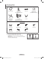
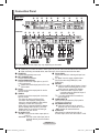
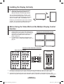
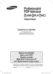
1
Professional PDP Display (PLASMA DISPLAY PANEL) PPM50M7F/PPM63M7F Owner’s Instructions Before operating the unit, please read this manual thoroughly, and retain it for future reference. ON-SCREEN MENUS Picture In Picture (PIP) Energy Saving SRS TruSurround XT Digital Natural Image engine Register your product at www.samsung.com/global/register Record your Model and Serial number here for future reference. ▪ Model _______________ ▪ Serial No. _______________ BN68-01364A-02Eng_1009.indd 1 2007-10-09 ¿ÀÈÄ 2:23:44 User Instructions Screen Image retention Do not display a still image (such as on a video game or when hooking up a PC to this PDP Display) on the plasma PDP Display panel for more than 2 hours as it can cause screen image retention. This image retention is also known as “screen burn”. To avoid such image retention, reduce the degree of brightness and contrast of the screen when displaying a still image. Height The PDP Display can normally operate only under 2000m(6562 feet) in height. It might abnormally function at a place over 2000m(6562 feet) in height, so do not install and operate there. Heat on the top of the PDP Display The top side of the product may be hot after long periods of use as heat dissipates from the panel through the vent hole in the upper part of the product. This is normal and does not indicate any defect or operation failure of the product. However, children should be prevented from touching the upper part of the product. The product is making a ‘cracking’ noise. A ‘cracking’ noise may occur when the product contracts or expands due to a change of surrounding environment such as temperature or humidity. This is normal and not a defect of the unit. Cell Defects The PDP Display uses a panel consisting of 1,230,000(SD-level) to 3,150,000(HD-level) pixels which require sophisticated technology to produce. However, there may be a few bright or dark pixels on the screen. These pixels will have no impact on the performance of the product. Avoid operating the PDP Display at temperatures below 5°C(41°F) A still image displayed too long may cause permanent damage to the PDP Panel. Watching the PDP Display in 4:3 format for a long period of time may leave traces of borders displayed on the left, right and center of the screen caused by the difference of light emission on the screen. Playing a DVD or a game console may cause similar effect to the screen. Damage caused by the above effects are not covered by the Warranty. After image on the Screen. Displaying still images from Video games and PC for longer than a certain period of time may produce partial afterimages. To prevent this effect, reduce the ‘brightness’ and ‘contrast’ when displaying still images for a long time. Warranty - Warranty does not cover any damage caused by image retention. - Burn-in is not covered by the warranty. Installation Be sure to contact an authorized service center when installing your PDP Display in a location with heavy dust, high or low temperatures, high humidity, chemical substances or where it will be operated for 24 hours a day such as in an airport, train station etc. Failure to do so may cause a serious damage to your PDP Display. Installing the product in an airtight place may shorten the lifetime of the product. © 2007 Samsung Electronics Co., Ltd. All rights reserved. English - 2 BN68-01364A-02Eng_1009.indd 2 2007-10-09 ¿ÀÈÄ 2:23:44 Contents General Information PC Display User Instructions ............................................. 2 Checking Parts................................................ 4 Control Panel ................................................. 5 Connection Panel............................................ 6 Viewing the Remote Control .......................... 7 Operation Switching Your PDP Display On and Off ......... 8 Installing the Display Vertically........................ 9 Before Using the Video Wall and the Multiple Display Control function..................... 9 Connecting Speakers.................................... 11 Viewing the Menus ........................................ 12 Freezing the Current Picture ......................... 12 Displaying the Setting Information ................ 12 Viewing an External Signal Sources ............. 13 Editing Device Names................................... 13 Setting up Your PC Software (Based on Windows XP) ............................... 31 Display Modes .............................................. 32 Setting the PC ............................................... 33 Setting the Home Theatre PC ....................... 34 Appendix Wall Mount Kit Specifications (VESA) ........... 34 Using the Stand-Base ................................... 35 Troubleshooting ............................................ 36 Specifications ................................................ 37 Picture Control Changing the Picture Standard ..................... 14 Customizing the Picture Settings .................. 14 Configuring Detailed Settings on the Picture .. 15 Selecting the Picture Size ............................. 16 Digital NR / Active Color / DNIe / Movie Plus ... 17 Sound Control Sound Features ............................................ 18 Function Description Time Features ............................................... 20 Language / Blue Screen / Melody / Energy Saving / HDMI Black Level ............... 21 Setting the Panel Button Lock....................... 22 Setting the Remote Control Button Lock....... 22 Setting Up Your Personal ID Number ........... 23 Setting the MDC (Multiple Display Control) .. 24 Setting the Multiple Screen ........................... 25 Selecting the Fan .......................................... 26 Using the Game Mode .................................. 27 Viewing the Picture in Picture (PIP) .............. 28 Screen Burn Protection ................................. 29 Setting the Screen Burn Protection Timer..... 30 ☛ ➢ Important Note Symbols Press English - 3 BN68-01364A-02Eng_1009.indd 3 2007-10-09 ¿ÀÈÄ 2:23:45 Checking Parts Owner’s Instructions Remote Control/ AAA Batteries (Not available in all locations) Power Cord Stand-Base (2EA) / Screws (4EA) (PPM50M7F) Ferrite Cores Power Cord(3301-001110)/ Speaker Wire(3301-001201) PC Cable Warranty Card/ Registration Card/ (Not available in all locations) Sold Separately S-Video Cable Component Cables Audio Cables HDMI/DVI Cable PC Audio Cable HDMI Cable Video Cable Ferrite Core (Speaker Wire, Power Cord) ➢ The ferrite cores are used to shield the cables from interference. When connecting a cable, open the ferrite core and clip it around the cable near the plug. Speaker Wire Power Cord English - 4 BN68-01364A-02Eng_1009.indd 4 2007-10-09 ¿ÀÈÄ 2:23:48 Control Panel Front Panel ➢ The product color and shape may vary depending on the model. 1 SOURCE( ) Displays a menu of all of the available input sources (AV, S-Video, Component, PC1, PC2, DVI, and HDMI). In the on-screen menu, use this button as you would use the ENTER button on the remote control. ➢ 2 MENU Press to see the on-screen menu of your PDP Display’s features. 3 4 − VOL + Press to increase or decrease the volume. In the on-screen menu, use the − VOL + buttons as you use the + and − buttons on the remote control. SEL Control the cursor in the menu. 5 (Power) button Press to turn the PDP Display on and off. 6 Power Indicator Blinks and turns off when the power is on and lights up in stand-by mode. 7 Remote Control Sensor Aim the remote control towards this spot on the PDP Display. The − VOL + and SEL buttons have the same function as the ▲/▼/◄/► buttons on the remote control. If the remote control no longer works or you have misplaced it, you can use the controls on the panel of the PDP Display. ➢ ➢ English - 5 BN68-01364A-02Eng_1009.indd 5 2007-10-09 ¿ÀÈÄ 2:23:49 Connection Panel Rear Panel 2 3 4 6 5 8 7 0 9 ! PPM50M7F 1 PPM63M7F 2 3 4 5 8 7 6 9 ! 0 1 or or or ➢ The product color and shape may vary depending on the model. ☛ Whenever you connect an audio or video system to your set, ensure that all elements are switched off. When connecting an external device, match the color of the connection terminal to the cable. 1 POWER IN Connect the supplied power cord. 2 EXT SPEAKER (8Ω) Connect external speakers. 3 DVI/PC/HDMI AUDIO IN Connect to the audio output jack on your PC or DVI component. AUDIO is an audio input jack for PC1 and PC2 modes. 4 DVI IN Connect to the video output jack for device with DVI output. 5 HDMI IN Connect to the video output jack of a device with DVI output. -This input can also be used as a DVI connection with separate analog audio inputs. An optional HDMI/DVI cable will be necessary to make this connection. -When using an optional HDMI/DVI adapter, the DVI analog audio inputs on your PDP Display allow you to receive left and right audio from your DVI device. 6 PC IN1/PC OUT1 - PC IN1: Connect to the video output jack on your PC. - PC OUT1: Connect to the video input jack on external devices (such as another display). ➢ 7 PC IN2 (BNC) Connect for RGB HV video signal input from a PC. “PC Mode” from this page onward means PC1/PC2 mode using RGB1(PC1) and RGB2(PC2). 8 RS-232C - IN: Used for the MDC (Multi-Display Control) function when connecting the PC or RS232C output of another PDP Display. - OUT: Used for the MDC function when connecting with the RS-232C input of another PDP Display. For further details about connections, refer to Page 10. 9 COMPONENT IN Video (Y/PB/PR) and audio (L/R) inputs for Component connections. 0 AV (VIDEO/AUDIO L/R) - IN: Video and audio inputs for external devices, such as a camcorder or VCR. - OUT: Outputs for external devices. ! S-VIDEO IN Video input for external devices with an S-Video output, such as a camcorder or VCR. ➢ ➢ English - 6 BN68-01364A-02Eng_1009.indd 6 2007-10-09 ¿ÀÈÄ 2:23:56 Viewing the Remote Control ➢ The performance of the remote control may be affected by bright light. 1 PDP display on 2 Direct channel selection Select to enter the numbers in the Timer. 3 Not available 4 Volume increase 5 Temporary sound switch-off 6 Volume decrease 7 Returns to the previous menu 8 Menu display 9 Move to the required menu option/Adjust an option value respectively 0 Picture effect selection ! Auto adjustment in PC mode @ PIP functions: - PIP activation or deactivation (PIP) - Select a position of the sub-picture (POSITION) # $ % ^ & * ( ) a b c d PDP display off Picture still Next channel(Not available) External input selection Previous channel (Not available) Information display Exit from any display Confirm your choice (store or enter) Sound effect selection Picture size Multiple display control Screen effect selection (screen burn protection) Continued... English - 7 BN68-01364A-02Eng_1009.indd 7 2007-10-09 ¿ÀÈÄ 2:24:00 Installing Batteries in the Remote Control 1 2 3 Remove the cover on the rear of the remote control by pressing the symbol ( ) downwards and then pulling firmly to remove it. Install two AAA size batteries. Make sure to match the “+” and “–” ends of the batteries with the diagram inside the compartment. Do not mix battery types, i.e. alkaline and manganese. Replace the cover by aligning it with the base of the remote control and pressing it back into place. Remove the batteries and store them in a cool and dry place if you won’t be using the remote control for a long time. The remote control can be used up to about 23 feet from the PDP Display. (Assuming typical PDP Display usage, the batteries last for about one year.) ➢ ➢ remote control doesn’t work! Check the following: ➢ If1.the Is the PDP Display power on? 2. Are the plus and minus ends of the batteries reversed? 3. Are the batteries drained? 4. Is there a power outage, or is the power cord unplugged? 5. Is there a special fluorescent light or a neon sign nearby? Switching Your PDP Display On and Off The power cord is attached to the rear of the PDP Display. 1 2 3 Plug the power cord into an appropriate socket. The main voltage is indicated on the rear of the PDP Display and the frequency is 50 or 60Hz. Press the (Power) button (On/Off) on the front of the PDP Display or press the ON button on the remote control to switch the PDP Display on. To switch the PDP Display off, press the (Power) button (On/Off) on the front of the PDP Display or press the OFF button on the remote control. ➢ English - 8 BN68-01364A-02Eng_1009.indd 8 2007-10-09 ¿ÀÈÄ 2:24:00 Installing the Display Vertically Samsung shall not be liable for damages caused by installing the product in a different direction from the figure above. You can install the PDP Display vertically. In this case, the fan automatically works. If you wish to stop the fan, position the PDP Display horizontally and then set Fan to Off in the Function menu. Please use a wall attachment panel when installing vertically. The unit must be installed with the menu buttons on the left when viewed from the front. Before Using the Video Wall and the Multiple Display Control function 1 2 Please create an ID for each PDP Display before installing them close together. It may be difficult to create IDs for the PDPs with the remote control when they are installed close to each other. (Refer to page 24) For details about Video Wall configuration and operation, refer to “Setting the Multiple Screen” on page 25. Example for 2x2 Video Wall function Examples of 2x2 Video Wall connections Rear of the PDP Display Distributor Y/PB/PR 2 1 L/R DVD 1 Connect the Component IN port of the distributor and the Component OUT port of the device (such as a DVD player) that supports the Component interface using the Component video and audio cables. 2 Connect the Component IN port on the rear panel of each PDP and the Component OUT port of the distributor using the Component video and audio cables. (A distributor has multiple Component OUT ports.) Continued... English - 9 BN68-01364A-02Eng_1009.indd 9 2007-10-09 ¿ÀÈÄ 2:24:04 Rear of the PDP Display 1 Connect the PC cable between the PC IN and PC OUT on the rear of each PDP in the form of daisy chain. 2 Connect the PC cable between the RGB IN on the rear of the last connected PDP and the PC OUT on the rear of the PC. Example for Multiple Display Control connections Rear of the PDP Display ➢ 1 Connect the RS232C cable between the RS-232C IN and RS-232C OUT on the rear of each PDP in the form of daisy chain. 2 Connect the RS232C cable between the RS-232C IN on the rear of the last connected PDP and the RS-232C OUT on the rear of the PC. Select ID input on the menu. Use the numeric buttons to enter the ID for PDP Display adjustment. You can operate the remote control only for the PDP Display that has been selected. For details about Multiple Display Control, refer to “Setting the MDC (Multiple Display Control)” on page 24. English - 10 BN68-01364A-02Eng_1009.indd 10 2007-10-09 ¿ÀÈÄ 2:24:10 Connecting Speakers ➢ Speakers are optional. You have to purchase the speakers separately. 1 Remove the screws on the rear of the PDP Display. PPM50M7F 2 PPM63M7F Hang the two “T” shaped hangers on the square holes on the rear of the PDP Display. PPM50M7F 3 PPM63M7F Tighten the PDP Display and the speaker bracket using the screws removed from the PDP Display. PPM50M7F PPM63M7F moving your PDP Display, do NOT hold the speaker connected to your PDP Display. It may ➢ When damage the bracket clamping the speaker and PDP Display together. It may also cause you to drop your PDP Display and incur a risk of personal damage and injury. English - 11 BN68-01364A-02Eng_1009.indd 11 2007-10-09 ¿ÀÈÄ 2:24:16 Viewing the Menus 1 2 3 4 5 Press the MENU button. The main menu is displayed on the screen. Its left side has five icons: Picture, Sound, Function, Setup, and Input. Press the ▲ or ▼ button to select one of the icons. Press the ENTER button to access the icon’s sub-menu. Press the ▲ or ▼ button to move to items in the menu. Press the ENTER button to enter items in the menu. Press the ▲/▼/◄/► button to change the selected items. Press the RETURN button to return to the previous menu. Press the EXIT button to exit from the menu. Picture Mode : Dynamic Contrast Brightness Sharpness Color G 50 Tint : Cool1 Color Tone Detailed Settings 100 45 75 55 R 50 More Move Enter Exit Freezing the Current Picture You can freeze the picture when watching a moving picture simply by pressing the “STILL” button. To return to normal viewing, press it again. mode, the Still function will be applied to the main and ➢ InsubPIPpicture at the same time. Displaying the Setting Information can view the setting status you select by pressing the ➢ You INFO button on the remote control. AV Picture Sound SRS TS XT −− : −− : Dynamic : Custom : Off English - 12 BN68-01364A-02Eng_1009.indd 12 2007-10-09 ¿ÀÈÄ 2:24:19 Viewing an External Signal Source You can switch between viewing signals from connected equipment, such as a VCR, DVD, Set-Top Box, and the PDP Display source. 1 2 3 4 Press the MENU button to display the menu. Press the ▲ or ▼ button to select Input, then press the ENTER button. Press the ENTER button again to select Source List. Press the ▲ or ▼ button to select the signal source, then press the ENTER button. Available signal sources: AV, S-Video, Component, PC1, PC2, DVI, HDMI Only connected devices can be selected. ➢ Input Source List Edit Name Move : AV Enter Return Source List AV S-Video Component PC1 PC2 DVI HDMI Move : −−−− : −−−− : −−−− : −−−− : −−−− : −−−− : −−−− Enter Return can select these options simply by pressing the SOURCE ➢ You button on the remote control. the INFO button on the remote control to see the current ➢ Press input source. Editing Device Names You can give a name to the external source. 1 2 3 4 5 6 Press the MENU button to display the menu. Press the ▲ or ▼ button to select Input, then press the ENTER button. Press the ▲ or ▼ button to select Edit Name, then press the ENTER button. Press the ▲ or ▼ button to select the external source to be edited, then press the ENTER button. Select the required device by pressing ▲ or ▼, then press the ENTER button. Available device names: VCR, DVD, D-VHS, Cable STB, HD STB, Satellite STB, AV Receiver, DVD Receiver, Game, Camcorder, DVD Combo, DHR (DVD HDD Recorder), PC Press the EXIT button to exit. Input Source List Edit Name Move : AV Enter Return Edit Name AV S-Video Component PC1 PC2 DVI HDMI Move : −−−− −−−− : −−−− VCR : −−−− DVD : −−−−D-VHS : −−−− Cable STB : −−−−HD STB : −−−− Satellite STB ▼ Enter Return English - 13 BN68-01364A-02Eng_1009.indd 13 2007-10-09 ¿ÀÈÄ 2:24:20 Changing the Picture Standard You can select the type of picture which best corresponds to your viewing requirements. 1 2 3 4 Picture Mode : Dynamic Contrast Brightness Sharpness Color G 50 Tint : Cool1 Color Tone Detailed Settings Press the MENU button to display the menu. Press the ENTER button to select Picture. Press the ENTER button again to select Mode. Select the required mode by pressing the ▲ or ▼ button, then press the ENTER button. Available modes: Dynamic, Standard, Movie The settings values may vary depending on the input source. (ex. Video, Component, PC, or HDMI) Press the EXIT button to exit. ➢ Move Enter Return Picture Dynamic Mode : Dynamic Standard Contrast Movie Brightness Sharpness Color G 50 R Tint Color Tone : Cool1 Detailed Settings Choose Dynamic for viewing the PDP Display during the day or when there is bright light in the room. Choose Standard for general PDP Display viewing mode. Choose Movie when viewing the movie. 100 45 75 55 50 More Move ➢ 100 45 75 55 R 50 More ➢ 5 Enter Return You can select these options simply by pressing the P.MODE button on the remote control. Customizing the Picture Settings Your PDP Display has several setting options that allow you to control the picture quality. 1 2 3 4 5 6 7 Press the MENU button to display the menu. Press the ENTER button to select Picture. Press the ENTER button again to select Mode. Select the required mode by pressing the ▲ or ▼ button, then press the ENTER button. Available modes: Dynamic, Standard, Movie Select the required option by pressing the ▲ or ▼ button, then press the ENTER button. When you are satisfied with your setting, press the ENTER button. Press the EXIT button to exit. Contrast – Brightness – Sharpness – Color – Tint In AV, S-Video modes of the PAL system, you cannot use the Tint function. Contrast – Brightness – Color Tone : PC Mode Press the ◄ or ► button until you reach the optimal setting. Color Tone: Cool2/Cool1/Normal/Warm1/Warm2 When the picture mode is set to Dynamic or Standard, Warm1 and Warm2 cannot be selected. Reset: Cancel/OK Select OK. You can return to the factory default picture settings. The reset function is set for each picture mode and color tone. ➢ ➢ Picture Mode : Dynamic Contrast Brightness Sharpness Color G 50 Tint : Cool1 Color Tone Detailed Settings 100 45 75 55 R 50 More Move Enter Contrast Return 100 Move Adjust Return Picture Mode : Dynamic Contrast Brightness Sharpness Color G 50 Tint Cool2 R : Cool1Cool1 Color Tone Detailed Settings Normal Warm1 Warm2 More Move Enter 100 45 75 55 50 Return ➢ English - 14 BN68-01364A-02Eng_1009.indd 14 2007-10-09 ¿ÀÈÄ 2:24:22 Making Detailed Picture Settings You can make detailed picture settings. 1 2 3 4 5 6 ➢ ➢ Picture Press the MENU button to display the menu. Press the ENTER button to select Picture. Press the ▲ or ▼ button to select Detailed Settings, then press the ENTER button. Select the desired option by pressing the ▲ or ▼ button, then press the ENTER button. Available options: Black Adjust, Dynamic Contrast, Gamma, White Balance, My Color Control, Edge Enhancement, Color Space, xvYCC. When you are satisfied with your setting, press the ENTER button. Press the EXIT button to exit. When the picture mode is set to Movie or Standard, Detailed Settings can be selected. If DNIe is set to Off or Demo, the Detailed Settings cannot be selected when the Picture mode is in Standard mode. Mode : Movie Contrast Brightness Sharpness Color G 50 Tint : Warm2 Color Tone Detailed Settings 80 45 10 53 R 50 More Move Enter Return Detailed Settings Black Adjust Dynamic Contrast Gamma White Balance My Color Control Edge Enhancement Color Space xvYCC Move : Off : Off :0 : Off : Auto : Off Enter Return Black Adjust: Off/Low/Medium/High You can directly select the black level on the screen to adjust the screen depth. Dynamic Contrast: Off/Low/Medium/High You can adjust the screen contrast so that the optimal contrast is provided. Gamma: -3 ~ +3 You can adjust the middle brightness of pictures. Press the ◄ or ► button until you reach the optimal setting. White Balance: R-Offset/G-Offset/B-Offset/R-Gain/G-Gain/B-Gain/Reset You can adjust the color temperature for more natural picture colors. R-Offset/G-Offset/B-Offset/R-Gain/G-Gain/B-Gain: Changing the adjustment value will refresh the adjusted screen. Select the desired option by pressing the ▲ or ▼ button, then press the ENTER button. Press the ◄ or ► button until you reach the optimal setting. Reset: The previously adjusted white balance will be reset to the factory defaults. My Color Control: Pink/Green/Blue/White/Reset This setting can be adjusted to suit your personal preferences. Pink/Green/Blue/White: Changing the adjustment value will refresh the adjusted screen. Select the desired option by pressing the ▲ or ▼ button, then press the ENTER button. Press the ◄ or ► button until you reach the optimal setting. When running the My Color Control feature, the current picture is captured as a still image before being displayed on the screen. Reset: The previously adjusted colors will be reset to the factory defaults. Edge Enhancement: Off/On You can emphasize object boundaries. Color Space: Auto/Wide You can set the color reproduction space for the input signal to Auto or Wide. xvYCC: Off/On Setting the xvYCC mode to On increases detail and color space when watching movies from an external device (ie. DVD player) connected to the HDMI or Component IN jacks. You must set the Picture Mode to Movie to enjoy this feature. The xvYCC function works only in Component or HDMI mode. If xvYCC function is active, PIP cannot be selected. ➢ ➢ ➢ English - 15 BN68-01364A-02Eng_1009.indd 15 2007-10-09 ¿ÀÈÄ 2:24:23 Selecting the Picture Size You can select the picture size which best corresponds to your viewing requirements. 1 2 3 4 Press the MENU button to display the menu. Press the ENTER button to select Picture. Press the ▲ or ▼ button to select Size, then press the ENTER button. Select the desired option by pressing the ▲ or ▼ button, then press the ENTER button. Available options: 16 : 9, Wide Zoom, Zoom, 4 : 3, Just Scan 16 : 9: Sets the picture to 16:9 wide mode. Wide Zoom: Magnify the size of the picture more than 4:3. Move the screen up/down using the ▲ or ▼ button after selecting the by pressing the ► or ENTER button. Zoom: Magnify the size of the picture vertically on screen. 4 : 3: Sets the picture to 4:3 normal mode. Just Scan: Displays the input scenes as they are without any cutoff when HDMI 720p, 1080i, 1080p signals are input. Certain external devices may feed the display an out of spec signal that may cause cutoff even when using the Just Scan feature. Press the EXIT button to exit. Picture More Size Digital NR Active Color DNIe Movie Plus Reset Move :4:3 : Off : On : On : On : OK Enter Return Size 16 : 9 Wide Zoom Zoom 4:3 Just Scan Move Enter Return ➢ 5 can change the picture size simply by pressing the P.SIZE button on the remote control. ➢ You on the input source, the picture size options may vary. ➢ Depending items available may differ depending on the selected mode. ➢ The ➢ In PC and DVI modes, only 16:9 and 4:3 modes can be selected. Positioning and Sizing the screen using Zoom Resizing the screen using Zoom enables the positioning and sizing of the screen in the up/down direction using the ▲ or ▼ button. Move the screen up/down using the ▲ or ▼ button after selecting by pressing the ◄ or ► button. Resize the screen vertically using the ▲ or ▼ button after selecting by pressing the ◄ or ► button. English - 16 BN68-01364A-02Eng_1009.indd 16 2007-10-09 ¿ÀÈÄ 2:24:24 Digital NR / Active Color / DNIe / Movie Plus 1 2 3 4 5 Press the MENU button to display the menu. Press the ENTER button to select Picture. Select the required option by pressing the ▲ or ▼ button, then press the ENTER button. Available options: Digital NR, Active Color, DNIe, Movie Plus When you are satisfied with your setting, press the ENTER button. Press the EXIT button to exit. Picture More Size Digital NR Active Color DNIe Movie Plus Reset Move :4:3 : Off : On : On : On : OK Enter Return Digital NR: Off/Low/Medium/High/Auto If the signal received by the PDP Display is weak, you can activate this feature to reduce any static and ghosting that may appear on the screen. Active Color: Off/On If you turn on this option, the colors of the sky and grass will be stronger and clearer for a more vivid on-screen picture. This function is not available in PC mode. This function is available in Dynamic mode. DNIe: Off/Demo/On This PDP Display includes the DNIe function to provide high visual quality. If you set DNIe to on, you can view the screen with the DNIe feature activated. If you set the DNIe to Demo, you can view the applied DNIe and normal pictures on the screen, for demonstration purposes. Using this function, you can view the difference in the visual quality. DNIeTM (Digital Natural Image engine) This feature brings you more detailed image with 3D noise reduction, detail enhancement, contrast enhancement and white enhancement. This function is not available in PC mode. When the picture mode is set to Movie, DNIe cannot be selected. Movie Plus: Off/On You can view more natural skin tones and clearer text, even in fast moving scenes. This function is not supported in the Wide Zoom,Zoom and Just Scan mode. In Movie Plus, HDMI (1080p), PC, and DVI modes are deactivated. ➢ ➢ ➢ ➢ ➢ ➢ ➢ English - 17 BN68-01364A-02Eng_1009.indd 17 2007-10-09 ¿ÀÈÄ 2:24:24 Sound Features 1 2 3 4 5 Press the MENU button to display the menu. Press the ▲ or ▼ button to select Sound, then press the ENTER button. Select the required option by pressing the ▲ or ▼ button, then press the ENTER button. Available options: Mode, Equalizer, SRS TS XT, Auto Volume, Internal Mute, Sound Select, Reset When you are satisfied with your setting, press the ENTER button. Press the EXIT button to exit. Sound Mode Equalizer SRS TS XT Auto Volume Internal Mute Sound Select Reset Move : Custom : Off : Off : Off : Main Enter Return < If Game Mode is On > Sound Mode: Standard/Music/Movie/Speech/Custom Mode : Custom You can select the type of special sound effect to be used Equalizer when watching a given broadcast. SRS TS XT : Off Auto Volume : Off Choose Standard for the PDP Display standard Internal Mute : Off factory settings. Sound Select : Main Choose Music when watching the music videos or Reset concerts. Choose Movie when watching movies. Move Enter Return Choose Speech when watching a show that is mostly dialog(i.e., news). Choose Custom to recall your personalized settings. You can select these options simply by pressing the S.MODE button on the remote control. Equalizer: Balance/100Hz/300Hz/1kHz/3kHz/10kHz The PDP Display has several settings which allow you to control Equalizer the sound quality. R/L Sound Balance Adjustment: To adjust the sound balance of the R/L speakers. R + + Bandwidth Adjustment(100Hz, 300Hz, 1kHz, 3kHz, 0 0 10kHz): To adjust the level of different bandwidth L frequencies. Balance 100Hz 300Hz 1kHz 3kHz 10kHz If you make any changes to these settings, the sound standard is automatically switched to Custom. Move Adjust Return SRS TS XT: Off/On TruSurround XT is a patented SRS technology that solves the problem of playing 5.1 multichannel content over two speakers. TruSurround delivers a compelling, virtual surround sound experience through any two-speaker playback system, even with the optional external PDP Display speakers. It is fully compatible with all multichannel formats. TruSurround XT, SRS and Symbol are trademarks of SRS Labs, Inc. TruSurround XT technology is incorporated under license from SRS Labs, Inc. ➢ ➢ ➢ ➢ ➢ Continued... English - 18 BN68-01364A-02Eng_1009.indd 18 2007-10-09 ¿ÀÈÄ 2:24:25 Auto Volume: Off/On Each broadcasting station has its own signal conditions, and it is not easy to adjust the volume every time the channel is changed. This feature lets you automatically adjust the volume of the desired channel by lowering the sound output when the modulation signal is high or by raising the sound output when the modulation signal is low. Internal Mute: Off/On If you want to hear the sound through separate speakers, turn the internal mute off. The VOL +, VOL -, S.MODE, and MUTE buttons do not operate when the Internal Mute is set to On. Sound Select: Main/Sub When the PIP feature is activated, you can listen to the sound of the sub (PIP) picture. − Main: Used to listen to the sound of the main picture. − Sub: Used to listen to the sound of the sub picture. Reset If Game Mode is On (refer to page 27), the Reset Sound function is activated. Selecting the Reset function after setting the equalizer resets the equalizer setting to the factory defaults. ➢ English - 19 BN68-01364A-02Eng_1009.indd 19 2007-10-09 ¿ÀÈÄ 2:24:25 Time Features 1 2 3 4 5 6 Press the MENU button to display the menu. Press the ▲ or ▼ button to select Setup, then press the ENTER button. Press the ▲ or ▼ button to select Time, then press the ENTER button. Select the desired option by pressing the ▲ or ▼ button, then press the ENTER button. Available options: Clock Set, Sleep Timer, Timer1, Timer2, Timer3 When you are satisfied with your setting, press the ENTER button. Press the EXIT button to exit. Setup Screen Burn Protection Language : English Time Game Mode : Off Blue Screen : Off Melody : Off PC Home Theatre PC : Off More Move Enter Return Time Clock Set Sleep Timer Timer1 Timer2 Timer3 : −− : −− : Off : Inactivated : Inactivated : Inactivated Clock Set You can set the PDP Display clock so that the current time is displayed when pressing the INFO button on the remote control. You must also set the time if you wish to use the automatic on or off timers. Move Enter Return − Press the ◄ or ► button to select Month, Day, Year, Hour, or Minute. Set these by pressing the ▲ or ▼ button. You can set the Month, Day, Year, Hour, and Minute directly by pressing the numeric buttons on the remote control. In the event of a power interruption or the set being turned off at the supply, the settings for the Clock will be lost. Sleep Timer You can select a time period of between 30 and 180 minutes after which the PDP Display automatically switches to standby mode. − Select the preset time interval (Off, 30, 60, 90, 120, 150, 180) by pressing the ▲ or ▼ button. Timer1 / Timer2 / Timer3 You can set the On/Off timers so that the PDP Display will switch on or off automatically at the time you select. You must set the clock first. − Press the ◄ or ► button to select the desired item below. Press the ▲ or ▼ button to adjust to the setting. On Time : Select hour, minute, and No/Yes. (To activate the On time, set to Yes.) Off Time : Select hour, minute, and No/Yes. (To activate the Off time, set to Yes.) Repeat : Select Once, Everyday, Mon - Fri, Mon - Sat, or Sat - Sun. Volume : Select the desired volume level. Source : Select the desired external device. You can set the hour, and minute directly by pressing the number buttons on the remote control. ➢ ➢ ☛ ➢ Power Off ☛ Auto When you set the timer “On”, the PDP Display will eventually turn off if no controls are operated for 3 hours after the PDP Display was turned on by timer. This function is only available in timer “On” mode and prevents overheating, which may occur if a PDP Display is on for too long time. English - 20 BN68-01364A-02Eng_1009.indd 20 2007-10-09 ¿ÀÈÄ 2:24:26 Language / Blue Screen / Melody / Energy Saving / HDMI Black Level 1 2 3 4 5 Press the MENU button to display the menu. Press the ▲ or ▼ button to select Setup, then press the ENTER button. Select the required option by pressing the ▲ or ▼ button, then press the ENTER button. When you are satisfied with your setting, press the ENTER button. Press the EXIT button to exit. Setup Screen Burn Protection Language : English Time Game Mode : Off Blue Screen : Off Melody : Off PC Home Theatre PC : Off More Move Enter Return Language It is variable depending on the model. When you start using the PDP Display for the first time, you must select the language which will be used for displaying menus and indications. Blue Screen: Off/On If no signal is being received or the signal is very weak, a blue screen automatically replaces the noisy picture. If you wish to continue viewing the poor picture, you must set the Blue Screen to Off. Melody: Off/Low/Medium/High The PDP Display power on/off melody sound can be adjusted. Energy Saving: Off/Low/Medium/High This feature adjusts the screen brightness depending on the surrounding lighting conditions. - Off: Switches off the Energy Saving mode. - Low: Operates in standard mode regardless of the surrounding illumination. - Medium: Enters medium power saving mode regardless of the surrounding illumination. - High: Enters maximum power saving mode regardless of the surrounding illumination. HDMI Black Level: Normal/Low Use this function to adjust the Black Level of the picture while in HDMI mode. English - 21 BN68-01364A-02Eng_1009.indd 21 2007-10-09 ¿ÀÈÄ 2:24:26 Setting the Panel Button Lock This feature allows you to lock the PDP Display panel buttons so that it cannot be operated via the PDP Display panel. It can, however, still be operated via the remote control. Only the remote control can release the panel lock setting, so keep the remote control away from unauthorized users. 1 2 3 4 5 6 Press the MENU button to display the menu. Press the ▲ or ▼ button to select Function, then press the ENTER button. Press the ENTER button again to select Safety Lock. Press the ENTER button again to select Key Lock. Select Off or On by pressing the ▲ or ▼ button, then press the ENTER button. Press the EXIT button to exit. Function Safety Lock Multi Control Video Wall Fan Move : Off Enter Return Safety Lock Key Lock IR Lock Change PIN Move : Off Enter Return Setting the Remote Control Button Lock This feature allows you to lock the remote control so that it cannot be operated via the remote control. It can, however, still be operated via the PDP Display Panel buttons. 1 2 3 4 5 ➢ ➢ Press the MENU button to display the menu. Press the ▲ or ▼ button to select Function, then press the ENTER button. Press the ENTER button again to select Safety Lock. Press the ▲ or ▼ button to select IR Lock, then press the ENTER button. Press the EXIT button to exit. When IR Lock is set to On, you will not be able to use the remote control even if the remote control button is pressed. To cancel the Remote Control Button Lock, press “0000” using the numeric buttons on the remote control then, IR Lock : Off is displayed. If you press the remote control buttons too quickly, the inputs may not be recognized. Press the buttons at an interval of about 2 seconds. Function Safety Lock Multi Control Video Wall Fan Move : Off Enter Return Safety Lock Key Lock IR Lock Change PIN Move : Off Enter Return IR Lock : On English - 22 BN68-01364A-02Eng_1009.indd 22 2007-10-09 ¿ÀÈÄ 2:24:27 Setting Up Your Personal ID Number This feature sets viewing restrictions and prevents unauthorized access to your PDP Display through a PIN (Personal Identification Number), which is a 4 digit number. 1 2 3 4 5 Press the MENU button to display the menu. Press the ▲ or ▼ button to select Function, then press the ENTER button. Press the ENTER button again to select Safety Lock. Press the ▲ or ▼ button to select Change PIN, then press the ENTER button. Press the number buttons to enter your current 4-digit pin number. The default pin number for a new PDP Display set is “0000”. Press the numeric buttons to enter your new 4-digit pin number. Re-enter your new pin number to confirm. Press the EXIT button to exit. If you forget the pin number, press the remote control buttons in the following sequence, which resets the pin to 0-0-0-0: MUTE, 1, 8, 6. ➢ 6 7 ➢ Function Safety Lock Multi Control Video Wall Fan Move : Off Enter Return Safety Lock : Off Enter Return Key Lock IR Lock Change PIN Move Change PIN Enter PIN Enter New PIN 0..9 : Enter PIN Return Change PIN Enter PIN * Enter New PIN 0..9 : Enter PIN Return English - 23 BN68-01364A-02Eng_1009.indd 23 2007-10-09 ¿ÀÈÄ 2:24:28 Setting the MDC (Multiple Display Control) This function enables you to easily control the connected PDP Displays from a PC by specifying IDs to connected PDP Displays. 1 2 3 4 5 6 ➢ ➢ ➢ Press the MENU button to display the menu. Press the ▲ or ▼ button to select Function, then press the ENTER button. Press the ▲ or ▼ button to select Multi Control, then press the ENTER button. Select the required option by pressing the ▲ or ▼ button, then press the ENTER button. Available options: ID Setup(00~99), ID Input When you are satisfied with your setting, press the ENTER button. Enter ID input number by using the numeric buttons. Select the ID setup number by using the numeric buttons. Press the EXIT button to exit. To operate the multi control function, PDP1 and PDP2 should be set in the ID Setup mode. When entering the ID Input number of PDP1 only PDP1 can be operated by the remote control. PDP2 cannot be operated with the remote control and displays the ID Input standby mode. For further details, refer to the MDC program guide. You can download the MDC program from the “www.samsung.com” download center. Function Safety Lock Multi Control Video Wall Fan Move : Off Enter Return Multi Control ID Setup ID Input : 00 : -- Enter Return ➢ ➢ Move Multi Control ID Setup ID Input Move : 00 00 : -- Enter Return Multi Control ID Setup ID Input You can select these options by simply pressing the MDC ➢ (Multiple Display Control) button on the remote control. : 00 : -- -- 0..9 : Enter ID Input Number Return English - 24 BN68-01364A-02Eng_1009.indd 24 2007-10-09 ¿ÀÈÄ 2:24:29 Setting the Multiple Screen You can get various display effects with many PDPs. 1 2 3 4 5 6 Press the MENU button to display the menu. Press the ▲ or ▼ button to select Function, then press the ENTER button. Press the ▲ or ▼ button to select Video Wall, then press the ENTER button. Press the ENTER button again. Press the ▲ or ▼ button to select On, then press the ENTER button. Select the required option by pressing the ▲ or ▼ button, then press the ENTER button. Available options: Format(Full/Natural), Screen Divider Format: Full: This option displays divided images on multiple PDP Displays without missing parts as if only the viewable part of the separate PDP Displays were simply part of a large single PDP Display. Natural: This option displays divided images on multiple PDP Displays as if the separate PDP Displays were simply part of a large single PDP Display. Therefore there are missing parts on the edge of the PDP Displays. Function Safety Lock Multi Control Video Wall Fan Move : Off Enter Return Video Wall Video Wall Format Screen Divider Move : Off : Full Enter Return Video Wall Video Wall Format Screen Divider Screen Divider: 2x2, 3x3, 4x4, 5x1, or 1x5 7 Press the EXIT button to exit. The PIP function and Picture Size do not work during the Video Wall operation. : On : Full Full Natural ➢ Move Enter Return Screen Divider 2x2 3x3 4x4 5x1 1x5 Move 1 1 1 1 Enter Return English - 25 BN68-01364A-02Eng_1009.indd 25 2007-10-09 ¿ÀÈÄ 2:24:30 Selecting the Fan Fans inside the PDP Display are used to lower the temperature of the tops and the front of the PDP Display. To reduce the noise of the fan, you may stop the fan by setting the Fan to “Off”. The temperature of the top and the front of the PDP Display may increase when you watch the PDP Display for a long period of time while the fan is stopped, but the PDP Display will operate normally. 1 2 3 4 5 ➢ ➢ ➢ Function Safety Lock Multi Control Video Wall Fan Press the MENU button to display the menu. Move Press the ▲ or ▼ button to select Function, then press the ENTER button. Press the ▲ or ▼ button to select Fan, then press the ENTER button. Select Off or On by pressing the ▲ or ▼ button, then press the ENTER button. Press the EXIT button to exit. If your PDP Display is displayed vertically, the fan automatically works. The message Check Fan is displayed if there is a fan problem. Please use the fan when the temperature is over 35 degrees(95˚F). : Off Enter Return English - 26 BN68-01364A-02Eng_1009.indd 26 2007-10-09 ¿ÀÈÄ 2:24:30 Using the Game Mode When connecting to a game console such as PlayStationTM or XboxTM, you can enjoy a more realistic gaming experience by selecting game menu. 1 2 3 4 5 Press the MENU button to display the menu. Press the ▲ or ▼ button to select Setup, then press the ENTER button. Press the ▲ or ▼ button to select Game Mode, then press the ENTER button. Select Off or On by pressing the ▲ or ▼ button, then press the ENTER button. Press the EXIT button to exit. on Game mode (Caution) ➢ Restrictions To disconnect the game console and connect another ➢ ➢ Setup Screen Burn Protection Language : English Time Game Mode : Off Blue Screen : Off Melody : Off PC Home Theatre PC : Off More Move Enter Return AV Game Mode external device, set Game Mode to Off. If you display the PDP Display menu in Game Mode, the screen shakes slightly. The mark ( ) appears on the screen which means that Game Mode is On with the selected source. If Game Mode is On : Picture Mode is automatically changed to Standard and users cannot change the mode. Sound Mode in the Sound menu is deactivated. Adjust the sound using the equalizer. The Reset Sound function is activated. Selecting the Reset function after setting the equalizer resets the equalizer to the factory defaults. If the picture is poor when an external device is connected to PDP Display, check if Game Mode is On. If it is On, set the Game Mode to Off. English - 27 BN68-01364A-02Eng_1009.indd 27 2007-10-09 ¿ÀÈÄ 2:24:31 Viewing the Picture in Picture (PIP) You can display a sub (PIP) picture within the main picture from external A/V devices. In this way you can display the video input from any connected device while monitoring other video inputs. 1 2 3 4 5 6 Press the MENU button to display the menu. Press the ▲ or ▼ button to select Setup, then press the ENTER button. Press the ▲ or ▼ button to select PIP, then press the ENTER button. Select the desired option by pressing the ▲ or ▼ button, then press the ENTER button. Available options: PIP(Off/On), Position When you are satisfied with your setting, press the ENTER button. Press the EXIT button to exit. PIP: Off/On You can activate or deactivate the PIP function. Main picture Component HDMI PC DVI Setup More Energy Saving : Off HDMI Black Level : Low PIP Move Enter Return PIP PIP Position Move : On : Enter Return Sub picture AV can select these options simply by pressing the PIP ➢ You button on the remote control. Position: / / / You can select a position of the sub-picture. English - 28 BN68-01364A-02Eng_1009.indd 28 2007-10-09 ¿ÀÈÄ 2:24:31 Screen Burn Protection To reduce the possibility of screen burn, this unit is equipped with screen burn prevention technology. This technology enables you to set picture movement up/down (Vertical Line) and side to side (Horizontal Dot). The Time setting allows you to program the time between movement of the picture in minutes. 1 2 3 4 5 6 Press the MENU button to display the menu. Press the ▲ or ▼ button to select Setup, then press the ENTER button. Press the ENTER button again to select Screen Burn Protection. Select the desired option by pressing the ▲ or ▼ button, then press the ENTER button. Available options: Pixel Shift, All White, Signal Pattern, Inverse, Timer, Side Gray When you are satisfied with your setting, press the ENTER button. Press the EXIT button to exit. Pixel Shift: Using this function, you can minutely move pixels on the PDP in the horizontal or vertical direction to minimize after images on the screen. − Set Pixel Shift to On by pressing the ▲ or ▼ button, then press the ENTER button. − Select the desired option by pressing the ▲ or ▼ button, then press the ENTER button. Available options: Horizontal Dot, Vertical Line, Time Optimum condition for pixel shift; ➢ PC Horizontal Dot Vertical Line Time (minute) 1 1 2 min Setup Screen Burn Protection Language : English Time Game Mode : Off Blue Screen : Off Melody : Off PC Home Theatre PC : Off More Move Enter Return Screen Burn Protection Pixel Shift All White Signal Pattern Inverse Timer Side Gray Move : Dark Enter Return Pixel Shift : On :2 :2 : 2 min Pixel Shift Horizontal Dot Vertical Line Time Move Enter Return AV/S-Video/ Component/HDMI 2 2 2 min ➢ The Pixel Shift value may differ depending on the monitor size (inches) and mode. All White: This function helps remove after images on the screen by changing the color of pixels to white. Use this function when there are remaining after-images or symbols on the screen, especially when you displayed a still image on the screen for a long time. Signal Pattern: This function helps remove after-images on the screen by moving all the pixels on the PDP according to a pattern. Use this function when there are remaining after-images or symbols on the screen, especially when you displayed a still image on the screen for a long time. Inverse: This function removes after-images on the screen by converting RGB input signal into GBR. Compared to All White and Signal Pattern function, this function can reduce burn in while viewing the PDP Display. Using the inverse function when viewing the PDP Display may cause the color reversal on the screen. (ex. Red colors may appear as green) Side Gray: When you watch PDP Display with the screen ratio of 4:3, the screen is prevented from any damage by adjusting the white balance on both the extreme left and right sides. Dark: When you set the screen ratio to 4:3, it darkens the left and right sides. Light: When you set the screen ratio to 4:3, it brightens the left and right sides. Continued... English - 29 BN68-01364A-02Eng_1009.indd 29 2007-10-09 ¿ÀÈÄ 2:24:32 To remove after-images on the screen, use either the All White, Inverse or Signal Pattern function. ➢ Although both of the three functions remove after images on the screen, Signal Pattern is more effective. after image removal function has to be executed for a long time (approximately 1 hour) to ➢ The effectively remove after images on the screen. If after-images are not removed after the execution of the function, repeat the function again. ➢ Press any button on the remote control to cancel this feature. Setting the Screen Burn Protection Timer You can set the timer for Screen Burn Protection (hours, minutes). If you start the operation to erase any residual image, the operation will be performed for the set period of time and then automatically finish. 1 2 3 4 5 6 7 Press the MENU button to display the menu. Press the ▲ or ▼ button to select Setup, then press the ENTER button. Press the ENTER button again to select Screen Burn Protection. Press the ▲ or ▼ button to select Timer, then press the ENTER button. Press the ENTER button again. Press the ▲ or ▼ button to select On, then press the ENTER button. Select the desired option by pressing the ▲ or ▼ button, then press the ENTER button. Available options: Timer, Mode, Period, Time Mode: All White, Signal Pattern, Inverse Period: Hour(1~24) Time: Min.(1~30) 8 Press the EXIT button to exit. Setup Screen Burn Protection Language : English Time Game Mode : Off Blue Screen : Off Melody : Off PC Home Theatre PC : Off More Move Enter Return Screen Burn Protection Pixel Shift All White Signal Pattern Inverse Timer Side Gray Move : Dark Enter Return Timer Timer Mode Period Time Move : On : All White : 1 Hour : 30 min. Enter Return English - 30 BN68-01364A-02Eng_1009.indd 30 2007-10-09 ¿ÀÈÄ 2:24:33 Setting up Your PC Software (Based on Windows XP) The Windows display-settings for a typical computer are shown below. The actual screens on your PC will probably be different, depending upon your particular version of Windows and your particular video card. But even if your actual screens look different, the same, basic set-up information will apply in almost all cases. (If not, contact your computer manufacturer or Samsung Dealer.) 1 2 3 4 5 Right click the mouse on the Windows Desktop, then click on Properties. The Display Properties will be displayed. Click on Settings tab, then set the Display Mode with reference to the Display Modes Table. You do not need to change the colors settings. Click on Advanced. A new settings dialog box will be displayed. Click on the Monitor tab, then set the Screen refresh rate with reference to the Display Modes Table. Set the Vertical Frequency and Horizontal Frequency individually if you can do so instead of setting the Screen refresh rate. Click on OK to close the window, then Click on OK button to the Display Properties window. Automatic re-booting may commence at this moment. English - 31 BN68-01364A-02Eng_1009.indd 31 2007-10-09 ¿ÀÈÄ 2:24:33 Display Modes Both screen position and size will vary depending on the type of PC monitor and its resolution. The resolutions in the table are recommended. (All resolutions between the supported limits are supported) D-Sub/DVI Input Resolution 640X350 720X400 640X480 640X480 640X480 640X480 800X600 800X600 800X600 800X60 1024X768 1024X768 1024x768 1024X768 1152X864 1280x960 1280x960 1280X1024 1280X1024 1280X1024 1280X1024 1600X1200 1920x1080P Horizontal Frequency (kHz) 31.5 31.5 31.5 37.9 37.5 43.3 37.9 48.1 46.9 53.7 48.4 56.5 60.0 68.7 67.5 60.0 75.1 64.0 74.6 78.0 91.1 75.0 67.5 Vertical Frequency (Hz) 70 70 60 72 75 85 60 72 75 85 60 70 75 85 75 60 75 60 70 75 85 60 60 PC DVI O O O O O O O O O O O O O O O O O O O O X O O O O O O O O O O O O O O O O X O X O X X O X O HDMI Input Resolution IBM 480p 576p 720p 1080i 1080p 640X480 720x480 720x576 1280x720 1280x720 1920x1080i 1920x1080i 1920x1080P 1920x1080P 1920x1080P 1920x1080P 1920x1080P Horizontal Frequency (kHz) 31.5 31.5 31.3 37.5 45.0 28.1 33.7 27.0 28.1 33.8 56.3 67.5 Vertical Frequency (Hz) 60 60 50 50 60 50 60 24 25 30 50 60 HDMI O O O O O O O O O O O O The interlace mode is not supported. The set might operate abnormally if a non-standard video format is selected. Separate and Composite modes are supported. SOG is not supported. HDMI is supported for DTV signals only. English - 32 BN68-01364A-02Eng_1009.indd 32 2007-10-09 ¿ÀÈÄ 2:24:34 Setting the PC the PDP Display to the PC mode by pressing the SOURCE ➢ Set button. 1 2 3 4 5 6 Press the MENU button to display the menu. Press the ▲ or ▼ button to select Setup, then press the ENTER button. Press the ▲ or ▼ button to select PC, then press the ENTER button. Select the desired option by pressing the ▲ or ▼ button, then press the ENTER button. Available options: Image Lock, Position, Auto Adjustment, Image Reset, Zoom When you are satisfied with your setting, press the ENTER button. Press the EXIT button to exit. Setup Screen Burn Protection Language : English Time Game Mode : Off Blue Screen : Off Melody : Off PC Home Theatre PC : Off More Move Enter Return PC Image Lock Position Auto Adjustment Image Reset Zoom Image Lock: Coarse/Fine The purpose of picture quality adjustment is to remove or reduce picture noise. Move Enter Return If the noise is not removed by Fine-tuning alone, then adjust Image Lock the frequency as best as possible (coarse) and Fine-tune Coarse 50 again. Fine 13 After the noise has been reduced, re-adjust the picture so that it is aligned on the center of screen. 1 Press the ▲ or ▼ button to select Coarse or Fine, then press the ENTER button. 2 Press the ◄ or ► button to adjust the screen quality, vertical stripes may appear or the picture may be blurry. Press the ENTER button. Move Enter Return Position Position Adjust the PC’s screen positioning if it does not fit the PDP Display screen. 1 Adjust the position by pressing the ▲/▼/◄/► button. 2 Press the ENTER button. Auto Adjustment Auto adjustment allows the PDP display to self-adjust to the incoming PC video signal. The values of fine, coarse and position are adjusted Move Enter Return automatically. Image Reset Auto Adjustment in Progress You can replace all image settings with the factory default Please wait. values. Zoom: Zoom/Position/Reset - Zoom: 0 - 1 - 2 - 3 - 4 - 5 - 6 Image Reset is completed. Option 0 represents a normal screen. Return The greater the number, the more magnified the screen. You can select the position and reset functions by selecting options 1 through 6. (If you select option 0, the position and reset functions are not selected.) If you have set the Zoom function between 1~6, you will not be able to select the Auto Adjustment function. - Position: You can adjust the position. - Reset: The previously adjusted settings will be reset to the factory defaults. English - 33 BN68-01364A-02Eng_1009.indd 33 2007-10-09 ¿ÀÈÄ 2:24:35 Setting the Home Theatre PC the PDP Display to the PC mode by pressing the ➢ Set SOURCE button. Setup Screen Burn Protection Language : English Time Game Mode : Off Blue Screen : Off Melody : Off PC Home Theatre PC : Off You can view higher quality pictures by configuring the screen settings in PC Mode. If you set the Home Theatre PC function to On, you can configure the Detailed Settings (when Picture Mode is set to Standard or Movie) in PC Mode. 1 2 3 4 5 ➢ More Press the MENU button to display the menu. Move Press the ▲ or ▼ button to select Setup, then press the ENTER button. Press the ▲ or ▼ button to select Home Theatre PC, then press the ENTER button. Select Off or On by pressing the ▲ or ▼ button, then press the ENTER button. Press the EXIT button to exit. This function is available only in PC mode. Enter Return Wall Mount Kit Specifications (VESA) Install your wall mount on a solid wall perpendicular to the floor. When attaching to other building materials, please contact your nearest dealer. If installed on a ceiling or slanted wall, it may fall and result in severe personal injury. Product Family LCD-TV PDP-TV/MONITOR inches VESA Spec. (A * B) Standard Screw 23 ~ 26 200 * 100 M4 32 ~ 40 200 * 200 M6 46 ~ 52 600 * 400 57 700 * 400 (No VESA) 57 ~ 70 800 * 400 80 ~ 1400 * 800 42 ~ 58 600 * 400 70 800 * 400 63 No VESA 80 ~ 1400 * 800 Quantity 4 M8 4 M8 6 4 Continued... English - 34 BN68-01364A-02Eng_1009.indd 34 2007-10-09 ¿ÀÈÄ 2:24:36 standard dimensions for wall mount kits are shown in the table. ➢ The When purchasing our wall mount kit, a detailed installation manual and all parts necessary for ➢ assembly are provided. Do not use screws longer than the standard dimension, as they may cause damage to the inside of ➢ the PDP Display set. wall mounts that do not comply with the VESA standard screw specifications, the length of the ➢ For screws may differ depending on their specifications. Do not use screws that do not comply with the VESA standard screw specifications. ➢ Do not use fasten the screws too strongly, this may damage the product or cause the product to fall, leading to personal injury. Samsung is not liable for these kinds of accidents. Samsung is not liable for product damage or personal injury when a non-VESA or non-specified wall ➢ mount is used or the consumer fails to follow the product installation instructions. Our 57” and 63” models do not comply with VESA Specifications. Therefore, you should use our ➢ dedicated wall mount kit for this model. ➢ Do not exceed 15 degrees tilt when mounting this PDP Display. Do not install your Wall Mount Kit while your PDP Display is turned on. It may result in personal injury due to electric shock. Using the Stand-Base ➢ Two or more people should carry the PDP. Never lay the PDP on the floor because of possible damage to the screen. Always keep the PDP upright. English - 35 BN68-01364A-02Eng_1009.indd 35 2007-10-09 ¿ÀÈÄ 2:24:36 Troubleshooting Before contacting a Samsung service center, perform the following simple checks. If you cannot solve the problem using the instructions below, note the model and serial number of the PDP Display and contact Samsung at 1-800-634-8770. No sound or picture Check that the power cord has been connected to a wall socket. Check that you have pressed the (Power) button (On/Off) on the front panel or press the ON button on the remote control. Check the picture contrast and brightness settings. Check the volume. Check if Internal Mute is set to On. Normal picture but no sound Check the volume. Check whether the volume MUTE button on the remote control has been pressed. No picture or black and white picture Adjust the Color settings. Sound and picture interference Try to identify the electrical appliance that is affecting the PDP Display, then move it further away. Plug the PDP Display into a different main socket. Remote control malfunctions Replace the remote control batteries. Clean the upper edge of the remote control (transmission window). Check that the “+” and “–” ends of the batteries are inserted correctly. Check that the batteries are drained. Screen is black and power indicator light blinks steadily On your computer check; Power, Signal Cable. The PDP Display is using its power management system. Move the computer’s mouse or press any key on the keyboard. On your equipment (STB, DVD, etc), check Power, Signal Cable. Press the Source button on the panel or remote control. Turn the PDP Display off and on. Picture distortion appears in the corner of the screen. If Just Scan is selected in some external devices, picture distortion may appear in the corner of the screen. This symptom is caused by external devices, not the PDP Display. English - 36 BN68-01364A-02Eng_1009.indd 36 2007-10-09 ¿ÀÈÄ 2:24:37 Specifications Model Name Screen Size (Diagonal) PPM50M7F PPM63M7F 50 inches 63 inches PC Resolution 1920 x 1080 @ 60 Hz Sound (Output) 10 W + 10 W Dimensions (WxHxD) Body With stand Weight Body With stand Environmental Considerations Operating Temperature Operating Humidity Storage Temperature Storage Humidity ➢ 1204.6 x 724.1 x 97.1 mm(47.4 x 28.5 x 3.8 inches) 1204.6 x 772.5 x 362.0 mm(47.4 x 30.4 x 14.3 inches) 1502.7 x 893.1 x 99.0 mm(59.2 x 35.2 x 3.9 inches) 1502.7 x 942.3 x 341.1 mm(59.2 x 37.1 x 13.4 inches) 43.5 kg(95.9 lbs) 44.5 kg(98.1 lbs) 63.9 kg(140.9 lbs) 68.9 kg(151.9 lbs) 10 °C to 40 °C (50 °F to 104 °F) 10% to 80%, non-condensing -20 °C to 45 °C (-4 °F to 113 °F) 5% to 95%, non-condensing This device is a Class B digital apparatus. Design and specifications are subject to change without prior notice. For the power supply and Power Consumption, refer to the label attached to the product. English - 37 BN68-01364A-02Eng_1009.indd 37 2007-10-10 ¿ÀÀü 10:06:38 This page is intentionally left blank. BN68-01364A-02Eng_1009.indd 38 2007-10-09 ¿ÀÈÄ 2:24:37 This page is intentionally left blank. BN68-01364A-02Eng_1009.indd 39 2007-10-09 ¿ÀÈÄ 2:24:37 Contact SAMSUNG WORLD-WIDE If you have any questions or comments relating to Samsung products, please contact the SAMSUNG customer care center. Communiquez avec SAMSUNG WORLD-WIDE Pour toute question ou commentaire se rapportant aux produits Samsung, veuillez communiquer avec le centre de service à la clientèle SAMSUNG. Contacte con SAMSUNG WORLD-WIDE Si tiene alguna pregunta o comentario referente a nuestros productos, por favor contacte con nuestro Servicio de Atención al Cliente. Contate a SAMSUNG EM TODO O MUNDO Caso tenha dúvidas ou comentários sobre os produtos da Samsung, entre em contato com o centro de atendimento ao cliente da SAMSUNG. Country Customer Care Center Web Site CANADA 1-800-SAMSUNG (726-7864) www.samsung.com/ca U.S.A 1-800-SAMSUNG (726-7864) www.samsung.com/us Country ARGENTINE BRAZIL CHILE COLOMBIA COSTA RICA ECUADOR EL SALVADOR GUATEMALA JAMAICA MEXICO PANAMA PUERTO RICO REP. DOMINICA TRINIDAD & TOBAGO VENEZUELA Customer Care Center 0800-333-3733 0800-124-421 4004-0000 800-SAMSUNG(726-7864) 01-8000112112 0-800-507-7267 1-800-10-7267 800-6225 1-800-299-0013 1-800-234-7267 01-800-SAMSUNG (726-7864) 800-7267 1-800-682-3180 1-800-751-2676 1-800-SAMSUNG(726-7864) 0-800-100-5303 Address Samsung Electronics Canada Inc., Customer Service 55 Standish Court Mississauga, Ontario L5R 4B2 Canada Samsung Electronique Canada Inc., Service à la Clientèle 55 Standish Court Mississauga, Ontario L5R 4B2 Canada Samsung Electronics America, Inc. 105 Challenger Road Ridgefield Park, NJ 07660-0511 Web Site www.samsung.com/ar www.samsung.com/br www.samsung.com/cl www.samsung.com/co www.samsung.com/latin www.samsung.com/latin www.samsung.com/latin www.samsung.com/latin www.samsung.com/latin www.samsung.com/mx www.samsung.com/latin www.samsung.com/latin www.samsung.com/latin www.samsung.com/latin www.samsung.com/latin BN68-01364A-02 BN68-01364A-02Eng_1009.indd 40 2007-10-09 ¿ÀÈÄ 2:24:37