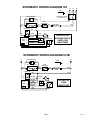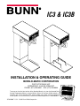
1
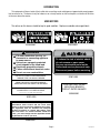
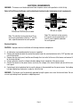
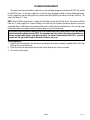
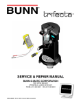
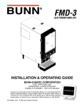
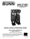
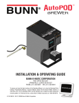
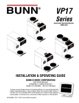
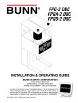
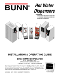
IC3 & IC3B
HA
LF
REA
DY
ON
ART
ST
LL
FU
OFF
HA
LF
DY
REA
ON
ART
ST
LL
FU
OFF
INSTALLATION & OPERATING GUIDE
BUNN-O-MATIC CORPORATION
POST OFFICE BOX 3227
SPRINGFIELD, ILLINOIS 62708-3227
PHONE: (217) 529-6601 FAX: (217) 529-6644
To ensure you have the latest revision of the Operating Manual, or to view the Illustrated Parts
Catalog, Programming Manual, or Service Manual, please visit the Bunn-O-Matic website, at
www.bunn.com. This is absolutely FREE, and the quickest way to obtain the latest catalog and
manual updates. For Technical Service, contact Bunn-O-Matic Corporation at 1-800-286-6070.
10792.0000F 11/12 ©1994 Bunn-O-Matic Corporation
BUNN-O-MATIC COMMERCIAL PRODUCT WARRANTY
Bunn-O-Matic Corp. (“BUNN”) warrants equipment manufactured by it as follows:
1) Airpots, thermal carafes, decanters, GPR servers, iced tea/coffee dispensers, MCP/MCA pod brewers thermal servers
and Thermofresh servers (mechanical and digital)- 1 year parts and 1 year labor.
2) All other equipment - 2 years parts and 1 year labor plus added warranties as specified below:
a) Electronic circuit and/or control boards - parts and labor for 3 years.
b) Compressors on refrigeration equipment - 5 years parts and 1 year labor.
c) Grinding burrs on coffee grinding equipment to grind coffee to meet original factory screen sieve analysis - parts
and labor for 4 years or 40,000 pounds of coffee, whichever comes first.
These warranty periods run from the date of installation BUNN warrants that the equipment manufactured by it will be
commercially free of defects in material and workmanship existing at the time of manufacture and appearing within the
applicable warranty period. This warranty does not apply to any equipment, component or part that was not manufactured
by BUNN or that, in BUNN’s judgment, has been affected by misuse, neglect, alteration, improper installation or operation,
improper maintenance or repair, non periodic cleaning and descaling, equipment failures related to poor water quality,
damage or casualty. In addition, the warranty does not apply to replacement of items subject to normal use including but
not limited to user replaceable parts such as seals and gaskets. This warranty is conditioned on the Buyer 1) giving BUNN
prompt notice of any claim to be made under this warranty by telephone at (217) 529-6601 or by writing to Post Office
Box 3227, Springfield, Illinois 62708-3227; 2) if requested by BUNN, shipping the defective equipment prepaid to an
authorized BUNN service location; and 3) receiving prior authorization from BUNN that the defective equipment is under
warranty.
THE FOREGOING WARRANTY IS EXCLUSIVE AND IS IN LIEU OF ANY OTHER WARRANTY, WRITTEN OR ORAL, EXPRESS OR IMPLIED, INCLUDING, BUT NOT LIMITED TO, ANY IMPLIED WARRANTY OF EITHER MERCHANTABILITY
OR FITNESS FOR A PARTICULAR PURPOSE. The agents, dealers or employees of BUNN are not authorized to make
modifications to this warranty or to make additional warranties that are binding on BUNN. Accordingly, statements by such
individuals, whether oral or written, do not constitute warranties and should not be relied upon.
If BUNN determines in its sole discretion that the equipment does not conform to the warranty, BUNN, at its exclusive option while the equipment is under warranty, shall either 1) provide at no charge replacement parts and/or labor (during the
applicable parts and labor warranty periods specified above) to repair the defective components, provided that this repair
is done by a BUNN Authorized Service Representative; or 2) shall replace the equipment or refund the purchase price for
the equipment.
THE BUYER’S REMEDY AGAINST BUNN FOR THE BREACH OF ANY OBLIGATION ARISING OUT OF THE SALE OF THIS
EQUIPMENT, WHETHER DERIVED FROM WARRANTY OR OTHERWISE, SHALL BE LIMITED, AT BUNN’S SOLE OPTION
AS SPECIFIED HEREIN, TO REPAIR, REPLACEMENT OR REFUND.
In no event shall BUNN be liable for any other damage or loss, including, but not limited to, lost profits, lost sales, loss of
use of equipment, claims of Buyer’s customers, cost of capital, cost of down time, cost of substitute equipment, facilities
or services, or any other special, incidental or consequential damages.
392, A Partner You Can Count On, AutoPOD, AXIOM, BrewLOGIC, BrewMETER, Brew Better Not Bitter, BrewWISE, BrewWIZARD, BUNN Espress, BUNN Family Gourmet, BUNN Gourmet, BUNN Pour-O-Matic, BUNN, BUNN with the stylized
red line, BUNNlink, Bunn-OMatic, Bunn-O-Matic, BUNNserve, BUNNSERVE with the stylized wrench design, Cool Froth,
DBC, Dr. Brew stylized Dr. design, Dual, Easy Pour, EasyClear, EasyGard, FlavorGard, Gourmet Ice, Gourmet Juice, High
Intensity, iMIX, Infusion Series, Intellisteam, My Café, Phase Brew, PowerLogic, Quality Beverage Equipment Worldwide,
Respect Earth, Respect Earth with the stylized leaf and coffee cherry design, Safety-Fresh, savemycoffee.com, Scale-Pro,
Silver Series, Single, Smart Funnel, Smart Hopper, SmartWAVE, Soft Heat, SplashGard, The Mark of Quality in Beverage
Equipment Worldwide, ThermoFresh, Titan, trifecta, Velocity Brew, Air Brew, Air Infusion, Beverage Bar Creator, Beverage Profit Calculator, Brew better, not bitter., BUNNSource, Coffee At Its Best, Cyclonic Heating System, Daypart, Digital
Brewer Control, Element, Nothing Brews Like a BUNN, Pouring Profits, Signature Series, Tea At Its Best, The Horizontal
Red Line, Ultra are either trademarks or registered trademarks of Bunn-O-Matic Corporation. The commercial trifecta®
brewer housing configuration is a trademark of Bunn-O-Matic Corporation.
Page 2
10792 080112
INTRODUCTION
This equipment will brew a batch of fresh coffee into an awaiting vessel and dispense at approximately room temperature to conserve ice. The brewer is only for indoor use on a sturdy counter or shelf and requires a minimum of 33 inches
of clearance above the counter.
USER NOTICES
The notices on this brewer should be kept in good condition. Replace unreadable or damaged labels.
03409.0000
03408.0000
! WARNING
Fill water tank before turning - on thermostat or connecting appliance
to power source.
Use only on a properly protected
circuit capable of the rated load.
Electrically ground the chassis.
Follow national/local electrical codes.
Do not use near combustibles.
FAILURE TO COMPLY RISKS EQUIPMENT
DAMAGE, FIRE, OR SHOCK HAZARD
To reduce the risk of electric shock,
do not remove or open cover.
No user-serviceable parts inside.
Authorized service personnel only.
Disconnect power before servicing.
37881.0000
READ THE ENTIRE OPERATING MANUAL
BEFORE BUYING OR USING THIS PRODUCT
FOR USE ONLY ON AN
INDIVIDUAL BRANCH
CIRCUIT RATED 20 AMPS
THIS APPLIANCE IS HEATED WHENEVER
CONNECTED TO A POWER SOURCE
00831.0000F 3/98 ©1998 BUNN-O-MATIC CORPORATION
00985.0000
00831.0000
As directed in the International Plumbing Code of the
International Code Council and the Food Code
Manual of the Food and Drug Administration (FDA),
this equipment must be installed with adequate
backflow prevention to comply with federal, state
and local codes. For models installed outside the
U.S.A., you must comply with the applicable Plumbing /Sanitation Code for your area.
00656.0001
Page 3
10792 051112
ELECTRICAL REQUIREMENTS
WARNING - The brewer must be disconnected from the power source until specified in Initial Set-Up.
Refer to Data Plate on the Brewer, and local/national electrical codes to determine circuit requirements.
L2 RED
L2 RED
WHITE
WHITE
NEUTRAL
L1 BLACK
GREEN
NEUTRAL
L1 BLACK
GREEN
L2
L2 RED
N
L1 BLACK
L2 RED
L1 BLACK
L2
L1
L1
GREEN
G
GREEN
G
200 volt ac models
120/208 and 120/240 volt ac models
Note: This electrical service consists
of 2 current carrying conductors (L1
and L2) and a separate conductor
for earth ground.
Note: This electrical service consists of 3 current carrying conductors (Neutral, L1 and L2)
and a separate conductor for earth ground.
Electrical Hook-Up
CAUTION – Improper electrical installation will damage electronic components.
1. An electrician must provide electrical service as specified.
2. Remove the top lid and rotate the control thermostat knob fully counterclockwise to the “OFF” position and
reinstall the top lid.
3. Remove the rear trunk panel, feed the cord through the strain relief at the rear of the brewer and connect it
to the terminal block.
4. Using a voltmeter, check the voltage and color coding of each conductor at the power source.
5. Connect the brewer to the power source and verify the voltage at the terminal block and reinstall the rear
trunk panel.
6. If plumbing is to be hooked up later be sure the brewer is disconnected from the power source. If plumbing
has been hooked up, the brewer is ready for Initial Set-Up.
WARNING – The brewer must be electrically grounded using the green screw near the terminal block. Do not
assume a plumbing line will provide an adequate ground.
CE REQUIREMENTS
• This appliance must be installed in locations where it can be overseen by trained personnel.
• For proper operation, this appliance must be installed where the temperature is between 5°C to 35°C.
• Appliance shall not be tilted more than 10° for safe operation.
• An electrician must provide electrical service as specified in conformance with all local and national codes.
• This appliance must not be cleaned by water jet.
• This appliance is not intended for use by persons (including children) with reduced physical, sensory or mental
capabilities, or lack of experience and knowledge, unless they have been given instructions concerning use of
this appliance by a person responsible for its safety.
• Children should be supervised to ensure they do not play with the appliance.
• If the power cord is ever damaged, it must be replaced by the manufacturer or authorized service personnel
with a special cord available from the manufacturer or its authorized service personnel in order to avoid a hazard.
• Machine must not be immersed for cleaning.
Page 4
10792 112912
PLUMBING REQUIREMENTS
This brewer must be connected to a cold water system with operating pressure between 30 (207 kPa) and 90
psi (620 kPa) from a 1⁄2" or larger supply line. A shut-off valve should be installed in the line before the brewer.
Install a regulator in the line when pressure is greater than 90 psi(620 kPa) to reduce it to 50 psi (345 kPa). The
water inlet fitting is 1⁄4" flare.
NOTE - Bunn-O-Matic recommends 1⁄4" tubing for installations of less than 25 feet and 3⁄8" for more than 25 feet
from the 1⁄2" water supply line. A coil of tubing in the water line will facilitate moving the brewer to clean the
countertop. Bunn-O-Matic does not recommend the use of a saddle valve to install the brewer. The size and shape
of the hole made in the supply line by this type of device may restrict water flow.
As directed in the International Plumbing Code of the International Code Council and the Food Code Manual
of the Food and Drug Administration (FDA), this equipment must be installed with adequate backflow prevention to comply with federal, state and local codes. For models installed outside the U.S.A., you must
comply with the applicable Plumbing /Sanitation Code for your area.
Plumbing Hook-Up
1. Attach the female fitting from the short piece of tubing on the strainer assembly (supplied) to the water inlet
fitting on the rear of the brewer.
2. Flush the water line and securely attach it to the flare fitting on the strainer assembly.
3. Turn on the water supply.
Page 5
10792 072408
INITIAL SET-UP
1.
2.
3.
4.
Remove the top lid from the brewer.
Rotate the control thermostat knob fully counterclockwise to the “OFF” position and replace the top lid.
Insert an empty funnel into the funnel rails.
Place an empty dispenser on the brewer base. Be prepared to empty the dispenser during these initial
steps.
5. Plug in the brewer, place the ON/OFF switch in the “ON” position, and momentarily press the START switch.
Water will flow into the tank and dispenser for five minutes and forty-five seconds. Empty the dispenser
when this first cycle stops and press the START switch again. Empty the dispenser when the second cycle
stops and press the START switch once more. During the third cycle, the tank will fill to its capacity and the
excess will flow from the funnel into the dispenser. Empty the dispenser when this third cycle stops.
6. Disconnect the brewer from the power source, remove the rear trunk panel, and turn the handle on the needle
valve approximately one-quarter turn counterclockwise to enable the flow of dilution water. This valve is fully
closed at the factory.
NOTE - The next step requires the use of a stopwatch to calculate the amount of dilution water flowing from the
nozzle in one minute. You’ll need to capture and measure the timed dilution water in a separate vessel than
the one used for the water flowing from the funnel.
7. Place a vessel under the brew funnel to catch the brew water. Use a hose or other means to divert the water
from the dilution nozzle to a separate container.
8. Connect the brewer to the power source. Simultaneously press the start switch to begin another brew cycle
and start the stop watch. Place the ON/OFF switch in the “OFF” position at exactly sixty-seconds (one-minute).
When the flow of water stops, measure the volume of the captured dilution water. It should be approximately
twenty-two ounces.
9. If not, disconnect the brewer from the power source, and adjust the handle on the needle valve clockwise to
decrease the amount of water or counterclockwise to increase the amount of dilution water as required.
10.Repeat steps 8 & 9 until the recommended dilution water volume (twenty-two ounces) is achieved.
11.Disconnect the brewer from the power source and reinstall the rear trunk panel.
12.Unplug the brewer, remove the top lid, rotate the control thermostat knob fully clockwise to the “ON” position
and replace the top lid.
13.Empty the dispenser.
14.Connect the brewer to the power source and wait for the ready light to glow indicating the water in the tank
has heated to brewing temperature (approximately 20 minutes). Some water will drip from the funnel during
this time; this is due to expansion and should not occur thereafter.
15.Begin another brew cycle and measure the total water volume from the dispenser. It should be approximately
3 gallons and 12 ounces. (396 ounces).
16.If not adjust the timer as required. See Adjusting Brew Volumes.
17.Start, and measure another cycle.
18.Repeat steps 16-17 until the recommended total water volume is achieved.
19.The brewer is now ready to brew a batch of freshly brewed room temperature coffee.
Page 6
10792 050405
ADJUSTING BREW VOLUMES
CAUTION - Disconnect the power source from the brewer prior to the removal of any panel for the replacement
or adjustment of any component.
NOTE: Prior to setting or modifying batch sizes, check that the brewer is connected to water supply, the tank is
properly filled, and a funnel and server are in place.
1. Modifying batch sizes. To modify a batch volume, first check that the SET/LOCK switch is in the “SET” position on the circuit board.
To increase a batch size. Press and hold the START or BREW switch until three clicks are heard. Release
the switch (Failure to release the switch within two seconds after the third click causes the volume setting to
be aborted and previous volume setting will remain in memory) and press it again one or more times. Each
time the switch is pressed, two seconds are added to the brew time period. Allow the brew cycle to finish in
order to verify that the desired volume has been achieved.
To decrease a batch size. Press and release the START or BREW switch once for every two-second interval
to be removed from the total brew time period; then immediately press and hold down the START or BREW
switch until three clicks are heard. Release the switch. (Failure to release the switch within two seconds after
the third click causes the volume setting to be aborted and previous volume setting will remain in memory).
Allow the brew cycle to finish in order to verify that the desired volume has been achieved.
2. Setting batch sizes. To set a batch volume, first check that the SET/LOCK switch is in the “SET” position on
the circuit board. Press and hold the START or BREW switch until three distinct clicks are heard (approximately 10 seconds) and then release the switch. (Failure to release the switch within two seconds after the
third click causes the volume setting to be aborted and previous volume setting will remain in memory). View
the level of the liquid being dispensed. When the desired level is reached, turn the ON/OFF switch to “OFF”
(lower). The brewer remembers this volume and will continue to brew batches of this size until the volume
setting procedure is repeated.
NOTE: When brewing tea, batch volumes will decrease due to absorption by the tea leaves.
3. Setting programming disable feature. If it becomes necessary to prevent anyone from changing brew times
once programmed, you can set the SET/LOCK switch to the “LOCK” position. This will prevent any programming to be done until switch is once again placed in the “SET” position.
CLEANING
CAUTION - Clean and sanitize your iced coffee brewer daily
1. Remove and thoroughly clean the entire brew funnel. The funnel must be free from any coffee particles or
residue.
2. Disconnect the brewer from the power source. Remove and thoroughly rinse the sprayhead. Wipe the sprayhead panel clean with a damp cloth.
3. Insert the deliming spring into the sprayhead fitting until no more than one inch is visible and move it in and
out 5 or 6 times. Insert the spring into the airvent hole in the sprayhead panel and move it in and out 5 or 6
times. Reattach the sprayhead.
4. Wash the entire outside surface of the brewer with a clean damp cloth.
CAUTION - Do not keep brewed coffee overnight. The dispenser must be cleaned and sanitized daily.
Page 7
10792 050405
OPERATING CONTROLS
A. Lighted On/Off Switch
ON - Placing the switch in the lighted upper position allows the start switch to activate a brew cycle.
OFF - Placing the switch in the lower position stops the brew cycle. Stopping a brew cycle after it has been
started will not stop the flow of water into the funnel until the tank syphons down to its proper level.
NOTE - The switch should always be placed in the “OFF” position after a brew cycle and whenever the brewer
is unattended.
B. Full/Half Batch Selector Switch
Placing the switch in the upper or lower position will set the brewer to deliver the desired brew volume. Both
selections can be adjusted to a desired brew volume (refer to ADJUSTING BREW VOLUMES).
C. Start Switch
Starts a brew cycle when the lighted On/Off switch is in the “ON” position.
D. Master ON/OFF Switch
Enables and disables power to the control board and other circuitry.
WARNING - This switch does not remove AC power from the entire dispenser. Disconnect power source before
servicing the dispenser.
COFFEE BREWING
1. Begin each brew cycle with a clean empty brew funnel and dispenser. (Be sure the dispenser lid doesn’t
interfere with the flow of dilution water.)
2. Insert a BUNN 3-gallon urn filter into the funnel.
3. Pour the recommended amount of fresh coffee into the filter.
4. Level the bed of coffee grounds by gently shaking.
5. Slide the funnel into the funnel rails until it stops.
6. Place the On/Off switch in the lighted “ON” position.
7. Place the batch selector switch in the desired position.
8. Momentarily press the start switch.
CAUTION - The funnel contains hot liquids. Remove funnel slowly.
9. Carefully remove the funnel and discard the used filter when coffee no longer drips from the funnel.
10.Place the lighted On/Off switch in the “OFF” position to prevent a false start.
11.Fresh Brewed Product is available at the faucet.
Page 8
10792 072408
MAIN ON/OFF SWITCH
(Late Models only)
READY INDICATOR
BLK
BLU
BLK
BLK
BLU
BLK
BREW
TIMER
TANK HEATER
RED
WHI
WHI/RED
1
2
3
4
5
BLK
LIMIT
THERMOSTAT
SW. & THERMOSTAT
ON/OFF SW
BLK
GRN
N
L2
RED
L1
WHI
SCHEMATIC WIRING DIAGRAM IC3
WHI/RED
WHI/RED
WHI
WHI/ORA
WHI/GRN
WHI/YEL
PIN
GRY
SOL
START SW
FULL/HALF SW
120/208 VOLTS AC
OR 120/240 VOLTS AC
3 WIRE + GND
SINGLE PHASE
10793.0000B 01/07
©1994 BUNN-O-MATIC CORPORATION
SCHEMATIC WIRING DIAGRAM IC3B
READY INDICATOR
L1
BLK
SW. & THERMOSTAT
BLK
L2
GRN
BLU
BLU
LIMIT
THERMOSTAT
BLK
TANK HEATER
RED
4000W
ON/OFF SW
BLK
BREW
TIMER
WHI/RED
1
2
3
4
5
RED
RED
WHI/RED
RED
WHI/ORA
WHI/GRN
WHI/YEL
PIN
GRY
WHI/RED
START SW
SOL
FULL/HALF SW
200 VOLTS AC
2 WIRE
SINGLE PHASE
10800.0000A 2/94
©1994 BUNN-O-MATIC CORPORATION
Page 9
10792 100807